

Page 1

SWITCHBLADE POWER SUPPLY UNIT
QUICK INSTALL GUIDE
Page 2

SwitchBlade Power Supply Unit Quick Install Guide
Document Number C613-04028-01 REV D.
Copyright © 2002-2003 Allied Telesyn International, Corp. North Creek Parkway, Suite
200, Bothell, WA 98011, USA.
All rights reserved. No part of this publication may be reproduced without prior written
permission from Allied Telesyn.
Allied Telesyn International, Corp. reserves the right to make changes in specifications
and other information contained in this document without prior written notice. The
information provided herein is subject to change without notice. In no event shall Allied
Telesyn be liable for any incidental, special, indirect, or consequential damages
whatsoever, including but not limited to lost profits, arising out of or related to this
manual or the information contained herein, even if Allied Telesyn has been advised of,
known, or should have known, the possibility of such damages.
All trademarks are the property of their respective owners.
Page 3
Quick Install Guide 3
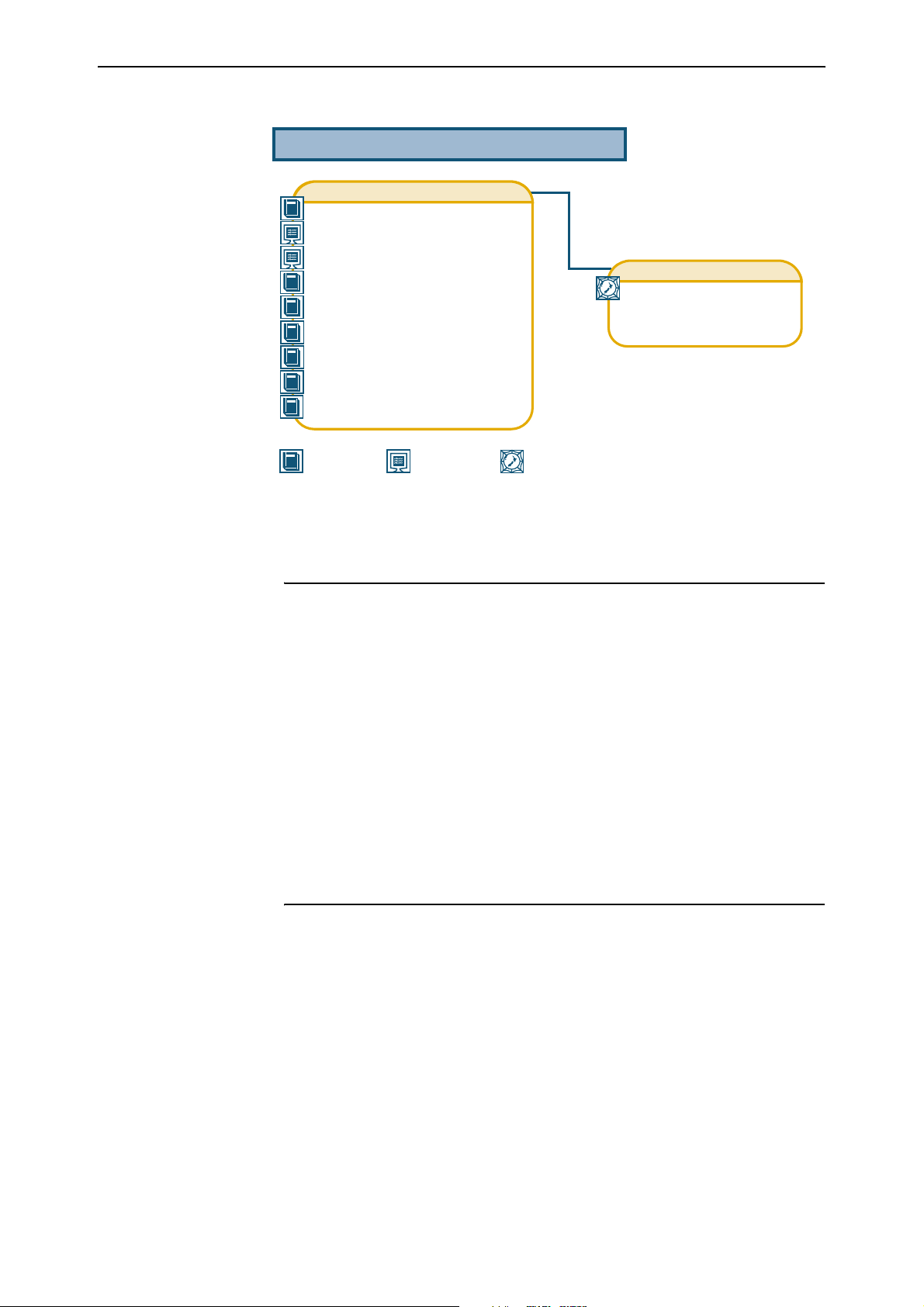
Documentation Roadmap
SwitchBlade
Safety and Statutory Information Booklet
Hardware Reference
Software Reference
Chassis & Fan Tray Quick Install Guide
Power Supply Unit Quick Install Guide
Switch Controller Quick Install Guide
Line Card Quick Install Guide
Bandwidth Expander Quick Install Guide
CAM Quick Install Guide
General Customer Support
Visit www.alliedtelesyn.co.nz for
the latest documentation, FAQs,
and support information.
Printed Acrobat PDF
Website
Models Covered By This Guide
This Quick Install Guide includes information on installing the following
power supply units (PSUs):
■ AT-SB4161 SwitchBlade AC Power Supply Unit
■ AT-SB4162 SwitchBlade AC Power Supply Unit
■ AT-SB4161-80 SwitchBlade DC Power Supply Unit
■ AT-SB4162-80 SwitchBlade DC Power Supply Unit
Quick Install Guide updates can be downloaded from
www.alliedtelesyn.co.nz/support/switchblade/.
Package Contents
C613-04028-01 REV D
The following items are included with each SwitchBlade PSU:
■ One AC or DC power supply unit
■ One IEC power cord (AC models only)
■ One Power Supply Unit Quick Install Guide
■ One Safety and Statutory Information booklet
■ One warranty card
The following related items that can be purchased separately:
■ Blank faceplates for PSU bays (AT-SB4192)
Contact your sales representative if any items are damaged or missing.
Page 4

4 SwitchBlade Power Supply Unit
Installing A Power Supply Unit (PSU)
All AC and DC versions of this equipment must be earthed.
PSUs can be hot swapped providing that the system has been designed for N+1
redundancy. The absolute minimum PSUs required for continued operation varies with
the specific configuration; however as a general rule, when swapping PSUs, the
SwitchBlade 8 (AT-SB4108) will continue to operate as long as two functional PSUs
remain in place. The SwitchBlade 4 (AT-SB4104) will continue to operate as long as one
functional PSU remains in place.
Follow these steps to install a PSU:
1. Read the safety information
The SwitchBlade Safety and Statutory Information booklet includes all
relevant safety information. A copy of the safety booklet is supplied with
each PSU. It can also be found on the CD-ROM that ships with every
switch controller and every chassis, or can be downloaded from
www.alliedtelesyn.co.nz/support/switchblade/.
2. Gather the tools and equipment you will need
To loosen or secure the PSU’s mounting screws you will need a Phillips #2
screwdriver.
3. Choose a PSU bay
If you are using a SwitchBlade model AT-SB104-80 or AT-SB104-00, either
PSU bay can be filled first.
If you are using a SwitchBlade model AT-SB4108-00, you should fill the
PSU bays from left to right. For this model, unless replacing an existing
PSU, choose the empty PSU bay that is nearest to the chassis’ front lefthand corner.
If you are using a SwitchBlade model AT-SB4108-60, fill the centre PSU bay
first, followed by the bays on either side. For this model it is not important
in which order the two side PSU bays are filled, as long as the centre bay is
filled first.
4. Prepare the PSU
In an antistatic environment, remove the PSU from its packing material. Be
sure to observe ESD precautions.
Do not attempt to install a PSU without observing correct antistatic
procedures. Failure to do so may damage the chassis or PSU. If you are unsure
what the correct procedures are, contact your authorised Allied Telesyn
distributor or reseller.
An ESD socket is provided on the front panel of the SwitchBlade chassis. The socket is
designed to be used in conjunction with an ESD wrist strap (see Figure 1 on page -5).
C613-04028-01 REV D
Page 5

Quick Install Guide 5
Figure 1: ESD socket on the SwitchBlade 8 chassis.
ESD socket
5. Remove the PSU bay faceplate or existing PSU
To remove a blank faceplate:
Loosen the faceplate’s four Phillips mounting screws until they disengage
from the chassis, then remove the faceplate.
Keep the faceplate for future use. If you remove a PSU, replace the faceplate to prevent
dust and debris from entering the chassis and to maintain proper airflow.
The switch and PSU may overheat or be damaged by dust and debris if PSU
bays are left uncovered.
To remove an existing PSU:
Loosen the PSU’s four Phillips screws until they disengage from the chassis.
Using the PSU’s handle, pull the PSU out of the chassis.
6. Insert the PSU
Slowly and carefully slide the PSU into the chassis (see Figure 2 on
page -6).
Firmly press the PSU home (until its front panel engages or nearly engages
the chassis).
Keep the PSU in a straight alignment and insert it slowly. Forcing a misaligned
PSU is likely to damage the chassis and PSU.
C613-04028-01 REV D
Page 6

7. Secure the PSU
8. Apply power to the PSU
For AC Models:
panel (for the triple feed model see Figure 3 on page -7, and for the dual
feed model see Figure 4 on page -7).
For the triple feed AT-SB4108-00 model, the connector for each PSU is the
one located directly behind its corresponding PSU bay.
For dual feed AT-SB4108-60 models, both feeds supply the centre PSU bay,
while the outside PSU bays are supplied by the feed located behind each
bay.
The operating voltages vary between SwitchBlade models. These are listed
below:
• For the triple feed models and 4 blade dual feed models, use a use a
voltage supply between 100 - 240V AC.
• For the dual feed 8 blade models, use a voltage supply between 200 240V AC.
Make sure the Standby switch is in the Run position.
Page 7

Quick Install Guide 7
Figure 3: AC power connectors on a CH8 with triple power inlets.
STANDBY
RESET RUN
AC INPUT
100-240V
8.0-4.0A
50-60Hz
SwitchBlade
AC INPUT
100-240V
8.0-4.0A
50-60Hz
4000
Figure 4: AC power connectors on a CH8 with dual power inlets.
STANDBY
RESET RUN
SwitchBlade
4000
AC INPUT
100-240V
8.0-4.0A
50-60Hz
For DC Models:
Read the Safety and Statutory Information booklet before connecting a
SwitchBlade PSU to a DC power source. A copy of the safety booklet is
included with each PSU. A PDF version is included on the Documentation and
Tools CD-ROM shipped with every switch controller and every chassis, or can
be downloaded from www.alliedtelesyn.co.nz/support/switchblade/.
Only trained and qualified personnel should connect a DC power supply. Due
to exposed terminals, DC powered SwitchBlades should only be installed in
Restricted Access Areas.
DC supply cable specifications:
• Three core cable is required. Where the unit is powered by a
centralised DC power, a UL listed tray cable should be used to connect
to this power source.
• Minimum core size: 3.3 mm
and 8.4 mm
2
(8 AWG) for the chassis type AT-SB4108-80.
2
(12 AWG) for chassis type AT-SB4104-80,
• Minimum cable rating: 600V, 90 degrees Celsius.
DC power supply specifications:
• 40-60 V DC, 48 V DC nominal.
Page 8

8 SwitchBlade Power Supply Unit
• Supports either positive grounded or negative grounded operation.
Circuit protection:
• Use a 20 Amp circuit breaker for chassis type AT-SB4104-80
• Use a 50 Amp circuit breaker for chassis type AT-SB4108-80
To connect the DC supply:
Ensure that the supply cable is not live.
a) Remove the transparent protective terminal cover (AT-SB4108-80 only).
b) Strip the supply cable wires to expose 8mm (0.31 in.) of bare conductor.
For AT-SB4108-80, terminate using a double-crimp terminal (Panduit
PMNF6 or equivalent) using an approved crimping tool.
c) Select a power inlet terminal.
For model AT-SB4104-80, the inlet terminal for each PSU is the terminal
on the chassis’ rear panel that is located directly behind the
corresponding PSU bay.
For the dual feed model AT-SB4108-80, both terminals supply the centre
PSU bay, while the outer PSU bays are supplied by the terminal located
behind each bay.
d) On the chassis’ rear panel:
Connect the ground wire to the ground terminal for the corresponding
PSU. (The terminals can be identified by the diagram on the switch’s
rear panel (see Figure 5 on page -9). Connect the positive feed to the +
(positive) terminal and the negative feed to the - (negative) terminal for
the corresponding PSU.
For the chassis model AT-SB4108-80, tighten the terminals to 1.8 Nm
(16 pound-force in) and replace the plastic terminal cover. For the
chassis model AT-SB4104-80, tighten the terminals to 1.4 Nm
(12 pound-force in).
Check that the PSU terminals are wired to the correct polarity. The PSUs will
be damaged if incorrectly connected.
e) Replace the transparent protective terminal cover (AT-SB4108-80 only).
f) Ensure that there are no exposed conductor strands.
g) Secure the supply cable (to the rack framework or similar object) so that
the connections are isolated from any forces applied to the cable.
h) Ensure that the circuit breaker is in the Off position.
i) Connect the supply-cable wires to the circuit breaker.
j) Energise the circuit breaker.
k) Make sure the Standby switch (on the chassis’ rear panel) is in the Run
position.
Page 9

Quick Install Guide 9
Figure 5: DC power terminals on a CH8 with three power inlets.
STANDBY
RESET RUN
9. Check the PSU’s LEDs
SwitchBlade
4000
Once you have inserted the PSUs and powered on the chassis, check the LEDs
for correct operation, using the table below as a guide.
Table: 1 LEDs on AC and DC PSUs.
LED State Function
DC Good Green The PSU is supplying power to the switch
Fan Good Green The PSU’s fan is functioning
Power Present Green The PSU is receiving power from its supply
circuit
If installed, the switch controller(s) have an LED labelled Power. This lights
green to indicate that at least one PSU is operational.
More troubleshooting information can be found in the SwitchBlade Hardware
Reference.
Where To Find More Information
For more information on the SwitchBlade, consult the following sources:
■ Documentation and Tools CD-ROM - The CD-ROM is bundled with every
switch controller and every chassis. It contains the complete
documentation set for your switch, its expansion options, and its
management tools.
■ SwitchBlade Safety and Statutory Information - This booklet provides safety
and statutory information for the SwitchBlade and its accessories.
■ The SwitchBlade Hardware Reference - This document provides detailed
information on the switch and its hardware features.
■ The SwitchBlade Software Reference - This document provides detailed
information on configuring the switch and its software.
■ The SwitchBlade Chassis and Fan Tray Quick Install Guide - This guide
outlines the procedure for installing the chassis and its fan tray.
Page 10

10 SwitchBlade Power Supply Unit
■ The SwitchBlade Switch Controller Quick Install Guide - This guide outlines
the procedure for installing switch controllers.
■ The SwitchBlade Line Card Quick Install Guide - This guide outlines the
procedure for installing line cards.
■ The SwitchBlade Bandwidth Expander Quick Install Guide - This guide
outlines the procedure for installing bandwidth expanders.
■ The CAM Quick Install Guide - This guide outlines the procedure for
installing Content Addressable Memory.
■ www.alliedtelesyn.co.nz/support/switchblade/ Our website provides an
extensive source of product and technical information.
C613-04028-01 REV D
 Loading...