


SwitchBlade Chassis and Fan Tray
Quick Install Guide

SwitchBlade Chassis and Fan Tray Quick Install Guide
Document Number C613-04029-01 REV C.
Copyright © 2002-2003 Allied Telesyn International, Corp. 19800 North Creek Parkway, Suite
200, Bothell, WA 98011, USA.
All rights reserved. No part of this publication may be reproduced without prior written
permission from Allied Telesyn.
Allied Telesyn International, Corp. reserves the right to make changes in specifications
and other information contained in this document without prior written notice. The
information provided herein is subject to change without notice. In no event shall Allied
Telesyn be liable for any incidental, special, indirect, or consequential damages
whatsoever, including but not limited to lost profits, arising out of or related to this
manual or the information contained herein, even if Allied Telesyn has been advised of,
known, or should have known, the possibility of such damages.
All trademarks are the property of their respective owners.
Quick Install Guide 3
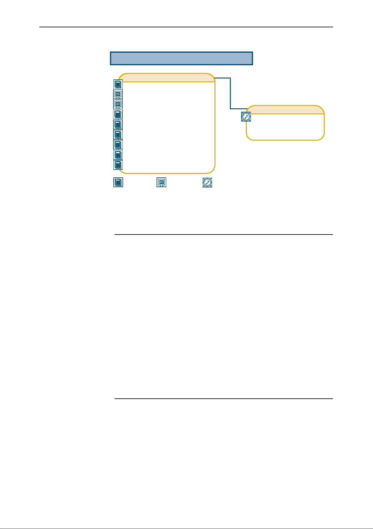
Documentation Roadmap
SwitchBlade
Safety and Statutory Information Booklet
Hardware Reference
Software Reference
Chassis & Fan Tray Quick Install Guide
Power Supply Unit Quick Install Guide
Switch Controller Quick Install Guide
Line Card Quick Install Guide
Bandwidth Expander Quick Install Guide
CAM Quick Install Guide
General Customer Support
Visit www.alliedtelesyn.co.nz for
the latest documentation, FAQs,
and support information.
Printed Acrobat PDF
Website
Models Covered By This Guide
This Quick Install Guide includes information on installing the following
components:
■ AT-SB4108-00 SwitchBlade 8 triple feed AC chassis.
■ AT-SB4108-60 SwitchBlade 8 dual feed AC chassis.
■ AT-SB4104-00 SwitchBlade 4 dual feed AC chassis.
■ AT-SB4108-80 SwitchBlade 8 dual feed DC chassis.
■ AT-SB4104-80 SwitchBlade 4 dual feed DC chassis.
■ AT-SB4152 SwitchBlade 8 fan tray.
■ AT-SB4151 SwitchBlade 4 fan tray.
Quick Install Guide updates can be downloaded from
www.alliedtelesyn.co.nz/support/switchblade/
C613-04029-01 REV C
Chassis Package Contents
The following items are included with each SwitchBlade chassis. These items
may arrive in more than one package. Contact your sales representative if any
items are damaged or missing.
■ One SwitchBlade chassis.
■ One SwitchBlade fan tray (pre-installed at factory).
■ One fan tray faceplate (pre-installed at factory).

4 SwitchBlade Chassis and Fan Tray
■ Blank faceplates for all but one switch controller bay and one line card bay
(pre-installed at factory). That is, eight faceplates for the SwitchBlade 8 and
four faceplates for the SwitchBlade 4.
■ One blank faceplate for each PSU bay (pre-installed at factory).
■ Two rack-mount brackets (pre-installed at factory).
■ One 19 inch rack-mount kit.
■ Two RS-232 DB9 cables for connecting switch controller RS-232 ASYN0
ports to a terminal or PC.
■ Two Ethernet patch cables for connecting switch controller RJ-45 ETH0
ports to a terminal or PC.
■ One SwitchBlade Documentation and Tools CD-ROM (which includes the
complete SwitchBlade documentation set and utilities).
■ One SwitchBlade Chassis and Fan Tray Quick Install Guide.
■ One Safety and Statutory Information booklet.
■ One warranty card.
■ One cable manager with four wire loops (with the SwitchBlade 8 only).
■ One rack crossbar (to support the chassis’s weight during installation).
Related items that can be purchased separately:
■ Blank faceplates for switch controller and line card bays (AT-SB4193).
■ Blank faceplates for PSU bays (AT-SB4192).
■ Fan trays (AT-SB4152 for the SwitchBlade 8 or AT-SB4151 for the
SwitchBlade 4).
■ Blank faceplates for fan tray bays (AT-SB4191 for the SwitchBlade 8 or
AT-SB4194 for the SwitchBlade 4).
Selecting A Site
The chassis can be installed in a standard 19-inch rack or on a level surface
such as a sturdy bench. When installing the chassis, choose a site that:
■ allows adequate airflow around the chassis and its vents.
■ is free of dust and moisture.
■ will allow the chassis and its components to operate within a temperature
range of 0 to 40º C (32 to 104º F) and a humidity range of 5 to 95% noncondensing.
■ has a reliable and earthed (grounded), preferably dedicated and filtered
power supply circuit.
■ does not expose cabling to sources of electrical noise, such as radios,
transmitters, broadband amplifiers, power lines, electric motors, and
fluorescent fixtures.
■ allows easy access to the chassis’s power and cable connections.
■ will allow all related network devices to be connected to the chassis
without exceeding maximum cable length limitations. See the SwitchBlade
Hardware Reference for cable length specifications.
C613-04029-01 REV C

Quick Install Guide 5
Installing A Chassis
All AC and DC versions of this equipment must be earthed.
Follow these steps to install a chassis:
1. Read the safety information
The SwitchBlade Safety and Statutory Information booklet includes all
relevant safety information. A copy of the safety booklet is supplied with
each chassis. A PDF version can be found on the CD-ROM that ships with
every switch controller and every chassis, or can be downloaded from
www.alliedtelesyn.co.nz/support/switchblade/.
2. Gather the tools and equipment you will need
To install the chassis in a rack you will need a Phillips #2 screwdriver,
screws and cage nuts.
Due to the chassis’ size and weight, it is recommended that you have someone assist you
with the rack-mounting procedure.
3. Choose a suitable site for the switch
Either a stable flat surface or a 19 inch rack. For more information, see
“Selecting A Site” earlier in this guide.
4. Unpack the chassis and place it in its operating location
If installing the chassis in a rack:
• Ensure the rack has sufficient space for the chassis and its associated
cables.
• Check the rack-mounting brackets. The brackets can be front or mid
mounted.
• Install the rack crossbar in the rack, just below the chassis’ intended
position (see Figure 1 on page -6). The crossbar will support the chassis’
weight during installation.
• Mount the chassis in the rack. This step is easier and safer if performed
by two people.
C613-04029-01 REV C

6 SwitchBlade Chassis and Fan Tray
Figure1: SwitchBlade rack crossbar.
SwitchBlade Support Bar
5. Remove any packaging and protective material
Inside the chassis: Check that the internal spaces are free of packaging and
protective material.
Outside the chassis: Check that all vents are free from obstruction.
6. Insert the blank faceplates (if not factory fitted)
When inserting a faceplate, make sure the faceplate’s metal back-panel is
aligned with the card guides (see Figure 2 on page -6).
Faceplates are mounted vertically in the SwitchBlade 8 chassis (AT-SB4108) and
horizontally in the SwitchBlade 4 chassis (AT-SB4104).
Figure2: Card guides.
bottom card guide
Carefully slide the faceplate into the chassis. The faceplate’s captive screws
should line up with the threaded holes on the chassis.
C613-04029-01 REV C

Quick Install Guide 7
7. Secure the blank faceplates
Press each faceplate home (until its front panel engages, or nearly engages,
the threaded holes inside the chassis).
Use the captive Phillips screws to secure each faceplate to the chassis (two
screws per faceplate).
Secure blank faceplates to all switch controller and line card bays that will not have
controllers or cards installed. The faceplates prevent dust and debris from entering the
switch and maintain proper airflow.
The switch may overheat or be damaged by dust and debris if bays are left
uncovered.
Fan Tray Package Contents
If you purchased a SwitchBlade chassis, the fan tray will be pre-installed in the
chassis.
If you purchased a SwitchBlade fan tray without also purchasing a
SwitchBlade chassis, the following items are included with each fan tray.
■ One fan tray.
■ One SwitchBlade Chassis and Fan Tray Quick Install Guide.
■ One warranty card.
Related items that can be purchased separately:
■ Blank faceplates for fan tray bays (AT-SB4191 for the SwitchBlade 8 or
AT-SB4194 for the SwitchBlade 4).
Contact your sales representative if any items are damaged or missing.
Installing A Fan Tray
Fan trays can be hot swapped. The switch will continue to operate for brief periods while
fan trays are exchanged.
C613-04029-01 REV C
Do not operate the switch for extended periods without an operational fan tray.
Doing so will cause the switch to overheat and shut down, and may also
damage the switch, switch controllers and line cards.

8 SwitchBlade Chassis and Fan Tray
Follow these steps to install a fan tray:
1. Read the safety information
The SwitchBlade Safety and Statutory Information booklet includes all
relevant safety information. A copy of the safety booklet is supplied with
each fan tray. A PDF version can be found on the CD-ROM that ships with
every switch controller and every chassis, or can be downloaded from
www.alliedtelesyn.co.nz/support/switchblade/.
2. Gather the tools and equipment you will need
To loosen or secure a fan tray you will need a Phillips #2 screwdriver.
3. Prepare the fan tray
In an antistatic environment, remove the fan tray from its packing material.
Be sure to observe ESD precautions.
Do not attempt to install a fan tray without observing correct antistatic
procedures. Failure to do so may damage the chassis or fan tray. If you are
unsure what the correct procedures are, contact your authorised Allied Telesyn
distributor or reseller.
An ESD socket is provided on the front panel of the SwitchBlade chassis. The socket is
designed to be used in conjunction with an ESD wrist strap (see Figure 3 on page -8).
Figure3: ESD socket on the SwitchBlade 8 chassis.
ESD socket
4. Detach the cable manager (for the SwitchBlade 8)
If a cable manager is attached to the fan tray’s front panel, remove it by
loosening its mounting screws and lifting it clear of the fan tray bay. If
network cables are attached, let the cable manager tilt forward, taking care
not to disturb any cable connections.
5. Remove the fan tray bay faceplate or existing fan tray
To remove a blank faceplate:
If a faceplate is attached to the chassis, use a Phillips #2 screwdriver to
loosen the faceplate’s two mounting screws until they disengage from the
chassis, then remove the faceplate.
To remove an existing fan tray:
Remove the fan tray faceplate (as described above).
Release the fan tray’s two locking mechanisms by pulling and rotating the
tray’s ejector levers until they have swivelled approximately 90 degrees (see
Figure 4 on page -9).
C613-04029-01 REV C

Quick Install Guide 9
Slide the fan tray out of the chassis, making sure to keep the tray in a
straight alignment so that it doesn’t jam.
When removing fan trays, avoid contact with spinning fan blades. Contact may
cause personal injury or fan damage.
Figure4: Fan tray ejectors.
6. Insert the new fan tray
With the fan tray’s ejector levers in the unlocked position (see Figure 4 on
page -9), slide the fan tray into the chassis, making sure to keep the tray in
a straight alignment so that it doesn’t jam (see Figure 5 on page -9).
Fan trays are mounted horizontally in the SwitchBlade 8 chassis (AT-SB4108) and
vertically in the SwitchBlade 4 chassis (AT-SB4104).
Figure5: Fan tray insertion.
C613-04029-01 REV C

10 SwitchBlade Chassis and Fan Tray
7. Secure the fan tray
Rotate the ejector levers until both locking mechanisms engage their holes
in the chassis.
8. Install the fan tray faceplate
Place the faceplate over the fan tray so that the plate’s two mounting
screws line up with the threaded holes on the fan tray (see Figure 6 on
page -10).
Tighten the mounting screws.
Figure 6: Installing fan tray faceplate.
9. Check the fan tray’s operation
If the chassis is receiving power and the stand-by switch is in the Run
position, you should hear the fans running and feel air movement across
the chassis vents.
10. Attach the cable manager
If you detached a cable manager to install the fan tray, re-attach it now.
A cable manager for the AT-SB4108 (SwitchBlade 8) can be purchased
separately, contact your authorised Allied Telesyn distributor or reseller for
more information.
C613-04029-01 REV C

Quick Install Guide 11
Where To Find More Information
Sources of further information:
■ The Documentation and Tools CD-ROM bundled with every switch
controller and every chassis, which contains the complete Documentation
Set for your switch and its expansion options, as well as tools for managing
the switch.
■ The SwitchBlade Safety and Statutory Information Booklet, provides safety
and statutory information for the SwitchBlade and its accessories.
■ The SwitchBlade Hardware Reference, provides detailed information on the
switch and its hardware features.
■ The SwitchBlade Software Reference, provides detailed information on
configuring the switch and its software.
■ The SwitchBlade Power Supply Unit Quick Install Guide, outlines the
procedure for installing AC and DC power supply units.
■ The SwitchBlade Switch Controller Quick Install Guide, outlines the procedure
for installing switch controllers.
■ The SwitchBlade Line Card Quick Install Guide, outlines the procedure for
installing line cards.
■ The SwitchBlade Bandwidth Expander Quick Install Guide, outlines the
procedure for installing bandwidth expanders.
■ The CAM Quick Install Guide, outlines the procedure for installing Content
Addressable Memory.
■ www.alliedtelesyn.co.nz/support/switchblade/.
C613-04029-01 REV C
 Loading...