

Page 1
How To|
Configure Load Balancer Redundancy on Allied Telesis
Routers and Switches
Introduction
In many Server Hosting environments, two requirements are important: maximising
throughput availability to each service, and minimising service downtime. This How To Note
contributes towards both these aims.
The Note is split into two parts. The first part illustrates both redundancy of servers and
redundancy of the load balancers themselves. The second part provides an optional
extension that enables you to control server selection without losing redundancy. This is
helpful when you prefer to have customers access a certain server, instead of balancing that
traffic. However, if that server fails, the customers need to use the alternate server instead.
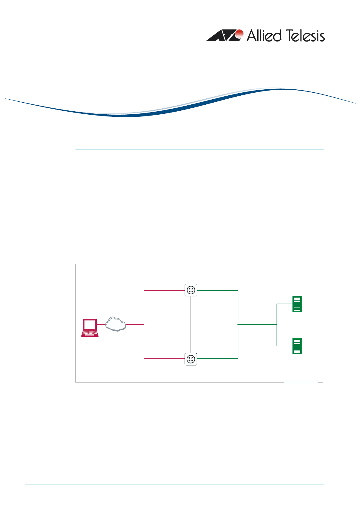
The examples
The network configuration for these examples is shown in the following figure.
public side private side
redundant
public
load balancer
VLAN 2
virtual address
172.214.1.2
client
The Note’s first example illustrates how to load balance web services, and includes:
• Load balancing of incoming web traffic to maximise throughput to web servers. It also
provides redundancy if a web server goes down.
Load Balancer 1
public address
172.214.1.3
public address
172.214.1.4
Load Balancer 2
private address
192.168.1.200
redundancy
management
VLAN 4
192.168.2.2
redundancy
management
VLAN 4
192.168.2.1
private address
192.168.1.201
private
VLAN 3
with VRRP
virtual
address
192.168.1.202
Web/SFTP server 1
192.168.1.1
Web/SFTP server 2
192.168.1.2
lb-redundancy.eps
C613-16088-00 REV A
• Redundancy between two load balancing routers. In the unlikely event of a router going
down, a backup router takes over as master and continues the load balancing work for
incoming web connections. Load balancer redundancy and VRRP ensure that clients and
servers access the same public and private addresses no matter which router is the master.
• A firewall to secure the LAN against attack. The firewall configuration changes
automatically if the backup router takes over the load balancing role.
www.alliedtelesis.com
Page 2

The Note’s second example extends the first example by showing how to control server
selection for SFTP (Secure File Transfer Protocol) traffic, while still providing server
redundancy if the preferred server fails.
For simplicity, these examples provide load balancing between two servers. You can easily
expand the examples by adding more servers.
What information will you find in this document?
As outlined above, the Note first describes basic load balancer redundancy. To configure
this, do all the following steps:
• "Configure Load Balancer 1" on page 3
• "Configure Load Balancer 2" on page 7
• "Create the Scripts" on page 9
Then the Note describes the optional extensions that let you control server selection. To
configure this, make all the following additions to the basic configuration:
• "Configure Load Balancing: Extra Commands" on page 10
• "Configure the Triggers: Extra Commands" on page 11
• "Modify the Scripts" on page 11
• "Create New Scripts" on page 12
Finally, the Note gives the complete extended configuration so you can verify your
configuration. Also, you may find it easier to copy this configuration to your router instead of
using the step-by-step configuration.
• "Commands: Load Balancer 1" on page 13
• "Commands: Load Balancer 2" on page 14
• "File: master.scp" on page 15
• "File: slave.scp" on page 15
• "File: sftp1down.scp" on page 15
• "File: sftp1up.scp" on page 15
Which products and software version does it apply to?
We created this configuration using AR440S routers and Software Version 275-05. However,
the configuration applies to the following products:
• AR44xS and AR450S Series routers
• AR750S, AR7x5 routers
• Rapier i Series switches
• AT-8800 Series switches
• AT-9800 Series switches
It requires software version 275-05 or later (except version 276-01, which lacks the
necessary trigger functionality).
Configure Load Balancer Redundancy on Allied Telesis Routers and Switches 2
Page 3

Example of Basic Redundancy
Configure Load Balancer 1
1. Name the router
Name this router LB-1.
set system name=LB-1
2. Create the VLANs
Create the three VLANs that this example uses:
• VLAN 2 for the public Internet side
create vlan=vlan2 vid=2
• VLAN 3 for the private LAN side
create vlan=vlan3 vid=3
• VLAN 4 for managing the load balancer redundancy
create vlan=vlan4 vid=4
3. Add ports to the VLANs
Add ports to the three VLANs.
add vlan=2 port=1
add vlan=3 port=2-4
add vlan=4 port=5
4. Configure IP on the VLANs
Enable IP.
enable ip
Give the public VLAN a unique public address. Note that public clients will not browse to
this address; they will browse to the virtual balancer’s IP address instead (see step 8).
add ip int=vlan2 ip=172.214.1.3 mask=255.255.255.0
Give the private VLAN a private address. Note that the servers will not use this address as a
gateway; they will use the VRRP virtual address instead (see step 7).
add ip int=vlan3 ip=192.168.1.200
Give the redundancy management VLAN a private address.
add ip int=vlan4 ip=192.168.2.2
Configure Load Balancer Redundancy on Allied Telesis Routers and Switches 3
Page 4

5. Configure the firewall
Enable the firewall.
enable firewall
Create a firewall policy.
create firewall policy=lb
Set the firewall session timeouts for TCP, UDP and other packet types, in minutes.
set firewall policy=lb tcptimeout=5 udptimeout=5 othertimeout=5
Add the public and private interfaces to the firewall policy.
add firewall policy=lb int=vlan2 type=public
add firewall policy=lb int=vlan3 type=private
Add the redundancy management VLAN to the firewall policy as a private interface.
add firewall policy=lb int=vlan4 type=private
You do not need to add firewall access rules at this step. This example uses triggered scripts
to dynamically add access rules, depending on which load balancer is the master (see step 9).
6. Disable the GUI and the HTTP server on port 80
You cannot use the router’s GUI or its HTTP server on port 80 when load balancing web
traffic. Therefore, you need to either disable the GUI and server, by using the following
commands:
disable gui
disable http server
or change the port that the server uses. For example, to change the port to 8080, use the
following command:
set http server port=8080
You can then use the GUI by pointing your browser to the router's private address and the
new port (in this example, 192.168.1.200:8080).
Note that this configuration uses some advanced settings that are not available through the
GUI, so you cannot use the GUI to create this configuration. You also cannot use the firewall
pages in the GUI to modify this configuration’s firewall settings, because the GUI does not
recognise this firewall policy. However, you can use the GUI to monitor the router.
Configure Load Balancer Redundancy on Allied Telesis Routers and Switches 4
Page 5

7. Configure VRRP
Configure VRRP for the private side interface. This step creates a virtual address for the
private interface of both load balancing routers. Private servers use this address as their
gateway to the Internet, instead of using the address of the private interface of either router.
This means the servers’ gateway is independent of which router is the master load balancer.
enable vrrp
create vrrp=2 over=vlan3 ipaddress=192.168.1.202
When you configure your servers, enter the VRRP address as their gateway address.
8. Configure load balancing
Enable load balancing.
enable lb
Add a resource pool for web traffic.
add lb respool=web selectmethod=roundrobin faillast=no
Add resources to the web resource pool. In this example, two resource servers share the
web traffic.
add lb resource=web1 ip=192.168.1.1 port=80 respool=web
add lb resource=web2 ip=192.168.1.2 port=80 respool=web
Add and enable the Virtual Balancer for the web traffic that is to be balanced. This step also
defines the load balancer’s virtual public address. Public clients browse to this address,
instead of browsing to either routers’ public address. This means that the clients’ destination
address is independent of which router is the master load balancer.
add lb virtualbalancer=web publicip=172.214.1.2 publicport=80
respool=web
enable lb virtualbalancer=web
Define the load balancing redundancy peer (Load Balancer 2 in the figure in "The
examples" on page 1).
set lb redundancy peerip=192.168.2.1 listenport=5000
redunip=172.214.1.2 publicint=vlan2 redunmask=255.255.255.0
enable lb redundancy
Configure Load Balancer Redundancy on Allied Telesis Routers and Switches 5
Page 6

9. Configure triggers
If one of the load balancers goes down, the firewall configuration needs to change. This
example uses triggers to make this change automatically, by running a script when the state
changes. See "Create the Scripts" on page 9 for instructions for making the scripts.
Enable triggers.
enable trigger
Set the router to run the script master.scp if it becomes the master load balancer. This
script adds firewall allow rules to support the resource pools.
create trigger=2 module=loadbalancer event=master
script=master.scp
Set the router to run the script slave.scp if it becomes the slave load balancer. This script
removes redundant firewall allow rules.
create trigger=3 module=loadbalancer event=slave script=slave.scp
10. Save the configuration
Save the configuration and set the router to use it when it restarts.
create config=lb_redun.cfg
set config=lb_redun.cfg
Configure Load Balancer Redundancy on Allied Telesis Routers and Switches 6
Page 7

Configure Load Balancer 2
Load balancer 2 is identical to load balancer 1, except for its:
• name (which is just a convenience and does not affect how it functions)
• public interface’s IP address
• private interface’s IP address
• load balancer redundancy peer, which is load balancer 1
Because the two load balancers are so similar, the following instructions do not explain the
steps—see the instructions for load balancer 1 for explanations.
1. Name the router
set system name=LB-2
2. Create the VLANs
create vlan=vlan2 vid=2
create vlan=vlan3 vid=3
create vlan=vlan4 vid=4
3. Add ports to the VLANs
add vlan=2 port=1
add vlan=3 port=2-4
add vlan=4 port=5
4. Configure IP on the VLANs
enable ip
add ip int=vlan2 ip=172.214.1.4 mask=255.255.255.0
add ip int=vlan3 ip=192.168.1.201
add ip int=vlan4 ip=192.168.2.1
5. Configure the firewall
enable firewall
create firewall policy=lb
set firewall policy=lb tcptimeout=5 udptimeout=5 othertimeout=5
add firewall policy=lb int=vlan2 type=public
add firewall policy=lb int=vlan3 type=private
add firewall policy=lb int=vlan4 type=private
Configure Load Balancer Redundancy on Allied Telesis Routers and Switches 7
Page 8

6. Disable the GUI and the HTTP server on port 80
Either:
disable gui
disable http server
Or:
set http server port=8080
7. Configure VRRP
enable vrrp
create vrrp=2 over=vlan3 ipaddress=192.168.1.202
8. Configure load balancing
enable lb
add lb respool=web selectmethod=roundrobin faillast=no
add lb resource=web1 ip=192.168.1.1 port=80 respool=web
add lb resource=web2 ip=192.168.1.2 port=80 respool=web
add lb virtualbalancer=web publicip=172.214.1.2 publicport=80
respool=web
enable lb virtualbalancer=web
set lb redundancy peerip=192.168.2.2 listenport=5000
redunip=172.214.1.2 publicint=vlan2 redunmask=255.255.255.0
enable lb redundancy
9. Configure triggers
enable trigger
create trigger=2 module=loadbalancer event=master
script=master.scp
create trigger=3 module=loadbalancer event=slave script=slave.scp
10. Save the configuration
create config=lb_redun.cfg
set config=lb_redun.cfg
Configure Load Balancer Redundancy on Allied Telesis Routers and Switches 8
Page 9

Create the Scripts
This section describes the scripts that the trigger facility runs when the master or slave load
balancer changes. Create the same scripts on both load balancer 1 and load balancer 2.
Create the scripts in a text editor on your PC. You can then open the router’s editor by using
the command edit master.scp (or edit slave.scp) and copy and paste the text of the script
into the editor. Use Ctrl+K+X to save the script and exit.
Alternatively, you can copy your PC-created script to a TFTP server and use the router’s
load command to download the files from the server.
! Script for when a load balancer becomes the master: master.scp
# Add the load balancer virtual interface (vlan2-1) to the firewall policy
# as a public interface.
#
add firewall policy=lb int=vlan2-1 type=public
# Add an allow rule for web traffic access. Note that this rule does not map
# to a private address, as expected on a NAT firewall. It just opens the port.
# The load balancer handles security and NAT redirection to the server.
#
add firewall policy=lb rule=1 int=vlan2-1 action=allow protocol=tcp port=80
# Set the VRRP priority level to a value higher than the slave's priority.
#
set vrrp=2 priority=200
! Script for when a load balancer becomes the slave: slave.scp
# Remove the load balancer virtual interface (vlan2-1).
#
delete firewall policy=lb int=vlan2-1
# Remove the associated access rule.
#
delete firewall policy=lb rule=1
# Set the VRRP priority level to a value lower than the master's priority.
#
set vrrp=2 priority=100
Configure Load Balancer Redundancy on Allied Telesis Routers and Switches 9
Page 10

Extension: Controlling Server Selection
Sometimes you may prefer your customers to access a certain server for certain traffic types.
However, if that server fails, they still require redundancy to an alternate server.
This section shows how to configure this. The example gives you control over server
selection for SFTP (Secure File Transfer Protocol) traffic, while providing server redundancy if
the preferred server fails. In this example, SFTP favours the first resource only (192.168.1.1).
It only uses the second resource if the first resource fails.
The load balancers use pings to monitor the health of each resource. When the primary
resource fails, this triggers a script to enable the secondary resource.
To provide this solution, you need to add the following steps:
• Configure Load Balancing: Extra Commands
• Configure the Triggers: Extra Commands
• Modify the Scripts
• Create New Scripts
Configure Load Balancing: Extra Commands
This section describes the commands you need to add to step 8 on page 5 for load
balancer 1 and page 8 for load balancer 2. These extra commands make load balancing act on
SFTP traffic as well as web traffic.
Add a resource pool for SFTP.
add lb respool=sftp selectmethod=roundrobin faillast=no
Add both SFTP resources to the SFTP resource pool. Note that SFTP is FTP encapsulated by
SSHv2 on port 22.
add lb resource=sftp1 ip=192.168.1.1 port=22 respool=sftp
add lb resource=sftp2 ip=192.168.1.2 port=22 respool=sftp
Disable SFTP2. This forces the load balancer to use SFTP1, which is the desired behaviour
because SFTP1 is the preferred server. Later in this configuration, we will create a trigger so
that the load balancer changes to SFTP2 if SFTP1 goes down.
disable lb resource=sftp2 immediately
Add and enable the Virtual Balancer for SFTP traffic.
add lb virtualbalancer=sftp publicip=172.214.1.2 publicport=22
respool=sftp affinity=no
enable lb virtualbalancer=sftp
Note that affinity is turned off. If resource 1 fails, this stops new connections from
automatically trying to use the failed resource.
Configure Load Balancer Redundancy on Allied Telesis Routers and Switches 10
Page 11

Configure the Triggers: Extra Commands
When the preferred server goes down or comes back up again, the load balancer needs to
change to the appropriate resource. This example uses triggers to make this change
automatically, by running a script when the server’s state changes.
This section describes the extra trigger commands you need to add on both load balancer 1
and load balancer 2. See "Create New Scripts" on page 12 for instructions for making the
scripts.
As part of its healthcheck feature, the load balancer regularly sends pings to check the health
of each server. If the server does not respond, the load balancer changes the resource state
to Closing. If the server starts to respond to the pings again, the load balancer changes the
resource state to Up. The following triggers activate a script when one of these state changes
occurs.
Set the router to run the script
sftp1down.scp if the first resource fails. This script enables
the second resource.
create trigger=4 module=loadbalancer event=resstate
resource=sftp1 lbstate=closing script=sftp1down.scp
Set the router to run the script sftp1up.scp if the first resource becomes available again.
This script disables the second resource.
create trigger=5 module=loadbalancer event=resstate
resource=sftp1 lbstate=up script=sftp1up.scp
Modify the Scripts
When the router is the master load balancer, it needs a rule to pass SFTP traffic through the
firewall. Similarly, this rule needs to be deleted when the router becomes the slave.
Add the following lines to the scripts on both load balancer 1 and load balancer 2. See
"Create the Scripts" on page 9 for the original scripts.
! master.scp
# Add an allow rule for SFTP traffic access over the SSHv2 port 22.
add firewall policy=lb rule=2 int=vlan2-1 action=allow protocol=tcp port=22
! slave.scp
# Remove the SFTP access rule.
delete firewall policy=lb rule=2
Configure Load Balancer Redundancy on Allied Telesis Routers and Switches 11
Page 12

Create New Scripts
This section describes the scripts that the trigger facility runs when the preferred SFTP
server goes down or comes back up again. The scripts enable and disable the second
resource. Load the same scripts onto both load balancer 1 and load balancer 2.
The load balancers send pings every 60 seconds to check the health of each resource.
Therefore, the load balancer can take up to 60 seconds to detect that the server has gone
down or come up again.
! Script for when the preferred server goes down: sftp1down.scp
# Enable resource 2 because resource 1 is Closing.
enable lb resource=sftp2
! Script for when the preferred server comes back up: sftp1up.scp
# Disable resource 2 because resource 1 is Up.
disable lb resource=sftp2 immediately
Configure Load Balancer Redundancy on Allied Telesis Routers and Switches 12
Page 13

Configuration Summary
This section shows the full extended configurations and scripts, without comments.
Commands: Load Balancer 1
set sys name=LB-1
create vlan=vlan2 vid=2
create vlan=vlan3 vid=3
create vlan=vlan4 vid=4
add vlan=2 port=1
add vlan=3 port=2-4
add vlan=4 port=5
enable ip
add ip int=vlan2 ip=172.214.1.3 mask=255.255.255.0
add ip int=vlan4 ip=192.168.2.2
add ip int=vlan3 ip=192.168.1.200
enable firewall
create firewall policy=lb
set firewall policy=lb tcpt=5
set firewall policy=lb udpt=5
set firewall policy=lb othert=5
add firewall policy=lb int=vlan3 type=private
add firewall policy=lb int=vlan2 type=public
add firewall policy=lb int=vlan4 type=private
dis gui
dis http serv
enable vrrp
create vrrp=2 over=vlan3 ipaddress=192.168.1.202
ena lb
add lb resp=web sel=roundrobin fail=no
add lb resp=sftp sel=roundrobin fail=no
add lb res=web1 ip=192.168.1.1 port=80 resp=web
add lb res=web2 ip=192.168.1.2 port=80 resp=web
add lb res=sftp1 ip=192.168.1.1 port=22 resp=sftp
add lb res=sftp2 ip=192.168.1.2 port=22 resp=sftp
dis lb res=sftp2 immediately
add lb virt=web publici=172.214.1.2 publicp=80 resp=web
add lb virt=sftp publici=172.214.1.2 publicp=22 resp=sftp aff=no
ena lb virt=web
ena lb virt=sftp
set lb redund peer=192.168.2.1 list=5000 reduni=172.214.1.2 publ=vlan2 redunm=255.255.255.0
ena lb redund
enable trigger
cre trigger=2 module=loadbalancer event=master script=master.scp
cre trigger=3 module=loadbalancer event=slave script=slave.scp
cre trigger=4 module=lb event=resstate resource=sftp1 lbstate=closing script=sftp1down.scp
cre trigger=5 module=lb event=resstate resource=sftp1 lbstate=up script=sftp1up.scp
Configure Load Balancer Redundancy on Allied Telesis Routers and Switches 13
Page 14

Commands: Load Balancer 2
set sys name=LB-2
create vlan=vlan2 vid=2
create vlan=vlan3 vid=3
create vlan=vlan4 vid=4
add vlan=2 port=1
add vlan=3 port=2-4
add vlan=4 port=5
enable ip
add ip int=vlan2 ip=172.214.1.4 mask=255.255.255.0
add ip int=vlan4 ip=192.168.2.1
add ip int=vlan3 ip=192.168.1.201
enable firewall
create firewall policy=lb
set firewall policy=lb tcpt=5
set firewall policy=lb udpt=5
set firewall policy=lb othert=5
add firewall policy=lb int=vlan3 type=private
add firewall policy=lb int=vlan2 type=public
add firewall policy=lb int=vlan4 type=private
dis gui
dis http serv
enable vrrp
create vrrp=2 over=vlan3 ipaddress=192.168.1.202
ena lb
add lb resp=web sel=roundrobin fail=no
add lb resp=sftp sel=roundrobin fail=no
add lb res=web1 ip=192.168.1.1 port=80 resp=web
add lb res=web2 ip=192.168.1.2 port=80 resp=web
add lb res=sftp1 ip=192.168.1.1 port=22 resp=sftp
add lb res=sftp2 ip=192.168.1.2 port=22 resp=sftp
dis lb res=sftp2 immediately
add lb virt=web publici=172.214.1.2 publicp=80 resp=web
add lb virt=sftp publici=172.214.1.2 publicp=22 resp=sftp aff=no
ena lb virt=web
ena lb virt=sftp
set lb redund peer=192.168.2.2 list=5000 reduni=172.214.1.2 publ=vlan2 redunm=255.255.255.0
ena lb redund
enable trigger
cre trigger=2 module=loadbalancer event=master script=master.scp
cre trigger=3 module=loadbalancer event=slave script=slave.scp
cre trigger=4 module=lb event=resstate resource=sftp1 lbstate=closing script=sftp1down.scp
cre trigger=5 module=lb event=resstate resource=sftp1 lbstate=up script=sftp1up.scp
Configure Load Balancer Redundancy on Allied Telesis Routers and Switches 14
Page 15

File: master.scp
add firewall poli=lb int=vlan2-1 type=public
add fire poli=lb ru=1 int=vlan2-1 action=allow prot=tcp po=80
add fire poli=lb ru=2 int=vlan2-1 action=allow prot=tcp po=22
set vrrp=2 prio=200
File: slave.scp
delete firewall poli=lb int=vlan2-1
delete firewall poli=lb ru=1
delete firewall poli=lb ru=2
set vrrp=2 prio=100
File: sftp1down.scp
ena lb res=sftp2
File: sftp1up.scp
dis lb res=sftp2 immediately
USA Headquarters | 19800 North Creek Parkway | Suite 200 | Bothell | WA 98011 | USA | T: +1 800 424 4284 | F: +1 425 481 3895
European Headquarters | Via Motta 24 | 6830 Chiasso | Switzerland | T: +41 91 69769.00 | F: +41 91 69769.11
Asia-Pacific Headquarters | 11 Tai Seng Link | Singapore | 534182 | T: +65 6383 3832 | F: +65 6383 3830
www.alliedtelesis.com
© 2006 Allied Telesyn Inc. All rights reserved. Information in this document is subject to change without notice. All company names,logos, and product designs that are trademarks or registered trademar ks are the property of their respective owners.
C613-16088-00 REV A
 Loading...