

Page 1

Release Note
Software Version 2.8.1
For AT-8800, Rapier i, AT-8700XL, AT-8600,
AT-9900, x900-48FE, AT-8900 and AT-9800 Series
Switches
and AR400 and AR700 Series Routers
Introduction .......................................................................................................4
Upgrading to Software Version 2.8.1 .................................................................5
Backwards Compatibility Issue when Upgrading ......................................... 5
Overview of New Features .................................................................................6
System Enhancements .......................................................................................9
Clearing System Parameters ....................................................................... 9
Extended Monitoring of CPU Utilisation ...................................................... 9
Command Reference Updates .................................................................. 11
Command Line Interface (CLI) Enhancements ..................................................15
More flexibility in Separating Parameters and Values ................................. 15
Additional Shortcuts when Editing ............................................................ 17
Command Reference Updates .................................................................. 18
File System Enhancement .................................................................................21
Command Reference Updates .................................................................. 21
Switching Enhancements ................................................................................. 25
Ordering Hardware Filters in 48-Port Switches .......................................... 25
Limiting Rapid MAC Movement ................................................................ 27
Route Update Queue Length .................................................................... 29
Removing a Description from a Switch Port .............................................. 30
Securing a Single VLAN through Switch Filters .......................................... 30
Change of Debug Command Syntax ........................................................ 32
Enhanced Static Switch Filtering on Ports within a Trunk Group ................ 32
Ethernet Protection Switching Ring (EPSR) ................................................ 32
Command Reference Updates .................................................................. 33
PPPoE Access Concentrator ..............................................................................47
Command Reference Updates .................................................................. 47
MSTP Enhancement .........................................................................................50
Command Reference Updates .................................................................. 50
STP Enhancement ............................................................................................51
Command Reference Updates .................................................................. 51
Asynchronous Port Enhancement .....................................................................52
Making Asynchronous Ports Respond More Quickly .................................. 52
Command Reference Updates .................................................................. 53
Internet Group Management Protocol (IGMP) Enhancements ...........................55
IGMP Proxy on x900 Series Switches ......................................................... 55
IGMP filtering extended to all IGMP message types .................................. 57
Monitoring reception of IGMP general query messages ............................ 59
Command Reference Updates .................................................................. 60
Internet Protocol (IP) Enhancements .................................................................66
Expanded number of Eth interfaces per physical interface ......................... 66
Expanded IP Troubleshooting .................................................................... 66
Page 2

2 Release Note
IP Route Preference Options ..................................................................... 66
IPv4 Filter Expansion ................................................................................. 67
Enhancements to Display of UDP Connections over IPv4 ........................... 68
Waiting for a Response to an ARP Request ............................................... 68
Adding Static ARP Entries with Multicast MAC Addresses ......................... 69
Enhanced Static ARP Entry Filtering on Ports within a Trunk Group ........... 70
Command Reference Updates .................................................................. 71
IPv6 Enhancements ..........................................................................................80
Display of UDP Connections over IPv6 ...................................................... 80
IPv6 Tunnel Expansion .............................................................................. 80
Command Reference Updates .................................................................. 81
L2TP Enhancements .........................................................................................82
Decoding Debug Output and Setting a Time Limit for Debugging ............. 82
Resetting General L2TP Counters .............................................................. 83
Handling PPP Link Negotiation Failures ..................................................... 83
Command Reference Updates .................................................................. 84
Open Shortest Path First Enhancements ...........................................................89
OSPF Interface Password .......................................................................... 89
NSSA Translator Role ................................................................................ 89
Redistributing External Routes .................................................................. 91
Command Reference Updates .................................................................. 94
BGP Enhancements ........................................................................................102
BGP Backoff Lower Threshold ................................................................ 102
BGP Peer and Peer Template Enhancements ........................................... 103
Displaying Routes Learned from a Specific BGP Peer ............................... 104
Command Reference Updates ................................................................ 105
MLD and MLD Snooping Enhancements ........................................................112
MLD Packet Formats ............................................................................... 112
ICMP type for MLDv2 Reports ................................................................ 112
MLD Snooping Group Membership Display ............................................ 113
Change of Maximum Query Response Interval for MLD .......................... 113
Command Reference Updates ................................................................ 114
Extension to Range of Classifier fields for x900 Switches ................................117
Command Reference Updates ................................................................ 117
QoS Enhancements ........................................................................................125
Port Groups ............................................................................................ 125
Storm protection .................................................................................... 126
Command Reference Updates ................................................................ 128
Secure Copy (SCP) .........................................................................................142
Configuring Secure Copy ....................................................................... 142
Loading using Secure Copy .................................................................... 144
Uploading using Secure Copy ................................................................. 145
Command Reference Updates ................................................................ 147
SSL Counter Enhancement .............................................................................158
Command Reference Updates ................................................................ 158
Firewall Enhancements ...................................................................................160
Firewall Licencing ................................................................................... 160
Disabling SIP ALG Call ID Translation ....................................................... 160
Displaying SIP ALG Session Details .......................................................... 161
Firewall Policy Rules Expansion ............................................................... 161
Displaying a Subset of Policy Rules .......................................................... 162
Command Reference Updates ................................................................ 162
Enhancements to IPsec/VPN ...........................................................................169
Responding to IPsec Packets from an
Unknown Tunnel ............................................................................. 169
Modifying the Message Retransmission Delay ......................................... 170
Retrying ISAKMP Phase 1 and 2 Negotiations ......................................... 171
VPN Tunnel Licencing ............................................................................. 172
Software Version 2.8.1
C613-10477-00 REV B
Page 3

Software Version 2.8.1 3
Command Reference Updates ................................................................ 173
SNMP MIBs ....................................................................................................186
SHDSL Line MIB ...................................................................................... 186
Logging SNMP operation ........................................................................ 187
Traps on OSPF state changes .................................................................. 188
Trap on VRRP topology changes ............................................................. 189
Traps on MSTP state and topology changes ............................................ 189
Restart Log ............................................................................................. 190
Trap on Login Failures ............................................................................. 190
VLAN-based port state changes .............................................................. 190
Trap on Memory Levels ........................................................................... 191
Command Reference Updates ................................................................ 192
CDP over WAN Interfaces ..............................................................................193
Command Reference Updates ................................................................ 193
Permanent Assignments on AR400 Series Routers ..........................................197
Software Version 2.8.1
C613-10477-00 REV B
Page 4

4 Introduction Release Note
Introduction
Allied Telesis announces the release of Software Version 2.8.1 on the products
in the following table. This Release Note describes the new features and
enhancements.
Product series Models
x-900-48FE x-900-48FE, x-900-48FE-N
AT-9900 AT-9924T, AT-9924SP, AT-9924T/4SP
AT-8900 AT-8948
AT-9800 AT-9812T, AT-9816GB
Rapier i Rapier 24i, Rapier 48i, Rapier 16fi
AT-8800 AT-8824, AT-8848
AT-8700XL AT-8724XL, AT-8748XL
AT-8600 AT-8624T/2M, AT-8624PoE, AT-8648T/2SP
AR700 AR725, AR745, AR750S, AR770S
AR400 AR415S, AR440S, AR441S, AR442S, AR450S
The product series that each feature and enhancement applies to are shown in
“Overview of New Features” on page 6. This Release Note should be read in
conjunction with the Installation and Safety Guide or Quick Install Guide,
Hardware Reference, and Software Reference for your router or switch. These
documents can be found on the Documentation and Tools CD-ROM packaged
with your router or switch, or:
www.alliedtelesis.com/support/software
This Release Note has the following structure:
1. Upgrading to Software Version 2.8.1
This section lists the names of the files that may be downloaded from the
web site.
2. Overview of New Features
This section lists the new features and shows the product families on which
each feature is supported.
3. Descriptions of New Features
These sections describe how to configure each new feature.
Caution: Information in this document is subject to change without notice and
does not represent a commitment on the part of Allied Telesis Inc. While every
effort has been made to ensure that the information contained within this
document and the features and changes described are accurate, Allied Telesis
Inc. can not accept any type of liability for errors in, or omissions arising from,
the use of this information.
Software Version 2.8.1
C613-10477-00 REV B
Page 5

Software Version 2.8.1 5
Upgrading to Software Version 2.8.1
Software Version 2.8.1 is available as a flash release that can be downloaded
directly from the Software/Documentation area of the Allied Telesis website:
www.alliedtelesis.com/support/software
Software versions must be licenced and require a password to activate. To
obtain a licence and password, contact your authorised Allied Telesis
distributor or reseller.
The following table lists the file names for Software Version 2.8.1.
Product name Release file GUI resource file CLI help file
AT-9924T/4SP 89-281.rez 9924_281-00_en_d.rsc 89-281a.hlp
AT-9924SP 89-281.rez 9924_281-00_en_d.rsc 89-281a.hlp
AT-9924T/4SP 89-281.rez 9924_281-00_en_d.rsc 89-281a.hlp
AT-8948 89-281.rez — 89-281a.hlp
x900-48FE 89-281.rez — 89-281a.hlp
AT-9812T sb-281.rez 9812_281-00_en_d.rsc 98-281a.hlp
AT-9816GB sb-281.rez 9816_281-00_en_d.rsc 98-281a.hlp
Rapier 24i 86s-281.rez r24i_281-00_en_d.rsc rp-281a.hlp
Rapier 48i 86s-281.rez r16i_281-00_en_d.rsc rp-281a.hlp
Rapier16fi 86s-281.rez r48i_281-00_en_d.rsc rp-281a.hlp
AT-8824 86s-281.rez 8824_281-00_en_d.rsc 88-281a.hlp
AT-8848 86s-281.rez 8848_281-00_en_d.rsc 88-281a.hlp
AT-8724XL 87-281.rez 8724_281-00_en_d.rsc 87-281a.hlp
AT-8748XL 87-281.rez 8748_281-00_en_d.rsc 87-281a.hlp
AT-8624PoE sr-281.rez — 86-281a.hlp
AT-8624T/2M sr-281.rez sr24_281-00_en_d.rsc 86-281a.hlp
AT-8648T/2SP sr-281.rez — 86-281a.hlp
AR770S 55-281.rez — 700-281a.hlp
AR750S 55-281.rez 750s_281-00_en_d.rsc 700-281a.hlp
AR725 52-281.rez 725_281-00_en_d.rsc 700-281a.hlp
AR745 52-281.rez 745_281-00_en_d.rsc 700-281a.hlp
AR440S 54-281.rez 440s_281-00_en_d.rsc 400-281a.hlp
AR441S 54-281.rez 441s_281-00_en_d.rsc 400-281a.hlp
AR442S 54-281.rez 442s_281-00_en_d.rsc 400-281a.hlp
AR415S 54-281.rez 415s_281-00_en_d.rsc 400-281a.hlp
AR450S 54-281.rez 450s_281-00_en_d.rsc 400-281a.hlp
Software Version 2.8.1
C613-10477-00 REV B
Backwards Compatibility Issue when Upgrading
The asexternal parameter of the set ospf command has changed. See OSPF
backward compatibility).
Page 6

6 Overview of New Features Release Note
Overview of New Features
The following table lists the new features and enhancements by product series.
For supported models, see “Introduction” on page 4.
AR400
AR7x5
AR750S
Rapier
AT-8800
AT-8700XL
AT-8600
AT-9800
AT-8900
x900-48FE
System: Clearing System Parameters
99999999999
AT-9900
System: Extended Monitoring of CPU Utilisation
CLI: Command Line Interface (CLI) Enhancements
File System: File System Enhancement
Switching: Ordering Hardware Filters in 48-Port Switches
Switching: Limiting Rapid MAC Movement
Switching: Route Update Queue Length
Switching: Removing a Description from a Switch Port
Switching: Securing a Single VLAN through Switch Filters
Switching: Change of Debug Command Syntax
Switching: Enhanced Static Switch Filtering on Ports within a
Trunk Group
Switching: Ethernet Protection Switching Ring (EPSR)
MSTP: MSTP Enhancement
STP: STP Enhancement
Asyn Ports: Making Asynchronous Ports Respond More
Quickly
PPPoE: PPPoE Access Concentrator
99999999999
99999999999
99999999999
9999
999
999
9 999999999
9999
99
99999
999
9999 999
99999999
99999999999
99999 9999
IGMP: IGMP Proxy on x900 Series Switches
IGMP: IGMP filtering extended to all IGMP message types
IGMP: Monitoring reception of IGMP general query messages
IP: Expanded number of Eth interfaces per physical interface
IP: Expanded IP Troubleshooting
IP: IP Route Preference Options
IP: IPv4 Filter Expansion
IP: Enhancements to Display of UDP Connections over IPv4
IP: Waiting for a Response to an ARP Request
IP: Adding Static ARP Entries with Multicast MAC Addresses
IP: Enhanced Static ARP Entry Filtering on Ports within a
Trunk Group
IPv6: Display of UDP Connections over IPv6
999
99999999999
99999999999
999
99999999999
99999999999
99999999999
99999999999
99999999999
99999999999
99999999
99999 9999
Software Version 2.8.1
C613-10477-00 REV B
Page 7

Software Version 2.8.1 7
AR400
AR7x5
AR750S
Rapier
AT-8800
AT-8700XL
AT-8600
AT-9800
AT-8900
x900-48FE
IPv6: IPv6 Tunnel Expansion
9
AT-9900
L2TP: Decoding Debug Output and Setting a Time Limit for
Debugging
L2TP: Resetting General L2TP Counters
L2TP: Handling PPP Link Negotiation Failures
OSPF: OSPF Interface Password
OSPF: NSSA Translator Role
OSPF: Redistributing External Routes
BGP: BGP Backoff Lower Threshold
BGP: BGP Peer and Peer Template Enhancements
BGP: Displaying Routes Learned from a Specific BGP Peer
MLD: MLD Packet Formats
MLD: ICMP type for MLDv2 Reports
MLD: MLD Snooping Group Membership Display
MLD: Change of Maximum Query Response Interval for MLD
Classifier: Extension to Range of Classifier fields for x900
Switches
QoS: Port Groups
99999 9999
99999 9999
99999 9999
99999999999
99999999999
99999999999
99999 9999
99999 9999
99999 9999
99999 9999
99999 9999
99 9999
99999 9999
999
999
QoS: Storm protection
SCP: Configuring Secure Copy
SCP: Loading using Secure Copy
SCP: Uploading using Secure Copy
SSL: SSL Counter Enhancement
Firewall: Firewall Licencing
Firewall: Disabling SIP ALG Call ID Translation
Firewall: Displaying SIP ALG Session Details
Firewall: Firewall Policy Rules Expansion
Firewall: Displaying a Subset of Policy Rules
IPSEC/VPN: Responding to IPsec Packets from an Unknown
Tunn el
IPSEC/VPN: Modifying the Message Retransmission Delay
IPSEC/VPN: Retrying ISAKMP Phase 1 and 2 Negotiations
IPSEC/VPN: VPN Tunnel Licencing
SNMP MIBs: SHDSL Line MIB
999
99999999999
99999999999
99999999999
99999999999
99999 9
99999
99999
99999
99999 9
99999
99999
99999
99999
9
SNMP MIBs: Logging SNMP operation
Software Version 2.8.1
C613-10477-00 REV B
99999999999
Page 8

8 Overview of New Features Release Note
AR400
AR7x5
AR750S
Rapier
AT-8800
AT-8700XL
AT-8600
AT-9800
AT-8900
x900-48FE
SNMP MIBs: Traps on OSPF state changes
99999999999
AT-9900
SNMP MIBs: Trap on VRRP topology changes
SNMP MIBs: Traps on MSTP state and topology changes
SNMP MIBs: Restart Log
SNMP MIBs: Trap on Login Failures
SNMP MIBs: VLAN-based port state changes
SNMP MIBs: Trap on Memory Levels
CDP: CDP over WAN Interfaces
Permanent Assignments on AR400 Series Routers
99999999999
9999 999
99999999999
99999999999
99999999999
99999999999
99999 9999
9
Software Version 2.8.1
C613-10477-00 REV B
Page 9

Software Version 2.8.1 9
System Enhancements
This Software Version includes the following enhancements to system
commands:
■ Clearing System Parameters
■ Extended Monitoring of CPU Utilisation
This section describes the enhancements. The new and modified commands to
implement them are described in Command Reference Updates.
Clearing System Parameters
The option none has been added to the following commands:
set system name={name|none}
set system contact={contact-name|none}
set system location={location|none}
This allows you to clear a previously specified system name, contact name or
location. For example, to clear the system name, use one of the commands:
set sys nam=none
set sys nam=””
set sys nam=
set sys nam
Command Changes
The following table summarises the modified commands:
Command Change
set system name New none option for name parameter
set system contact New none option for contact parameter
set system location New none option for location parameter
Extended Monitoring of CPU Utilisation
This Software Version includes a new feature for monitoring CPU utilisation.
You can now set the router or switch to capture data about which specific
functions the CPU is executing, and the level of instantaneous usage the CPU is
experiencing. This allows you, in conjunction with your authorised distributor
or reseller, to diagnose the causes of high rates of CPU utilisation on the router
or switch.
Software Version 2.8.1
C613-10477-00 REV B
You can set the router or switch to capture data continuously, or only when the
CPU experiences a specific level of instantaneous usage. The router or switch
holds up to 500 entries (10 seconds) of data about CPU utilisation.
Page 10

10 System Enhancements Release Note
To capture data when the CPU is experiencing a specific amount of
instantaneous usage, set the start and start percentages with the command:
activate cpu extended start=1..100 [stop=1..100]
When a start percentage is set, the router or switch automatically disables
extended monitoring once it has 500 data entries.
To enable extended monitoring, use the command:
enable cpu extended
This command also lets you capture data immediately, without first setting
start and stop percentages. This adds data entries continuously, until you stop
it. Only the last 10 seconds of data entries are stored.
To stop capturing data, and reset the start and stop parameters if they are set,
use the command:
disable cpu extended
To remove data entries and reset the start and stop parameters in the activate
cpu extended command, use the command:
reset cpu utilisation
This command interrupts active data capturing for a specific event. However,
monitoring remains enabled, and continues to collect data. This means you can
capture data for a particular event without having to disable and re-enable this
feature.
Command Changes
The following table summarises the new and modified commands:
Command Change
activate cpu extended New command.
disable cpu extended New command.
enable cpu extended New command.
reset cpu utilisation Modified command.
show cpu New extended parameter in command.
New output field when extended parameter is used.
Software Version 2.8.1
C613-10477-00 REV B
Page 11

Software Version 2.8.1 11
Command Reference Updates
This section describes each new command and the changed portions of
modified commands and output screens. For modified commands and output,
the new parameters, options, and fields are shown in bold.
activate cpu extended
Syntax ACTivate CPU EXTended STARt=1..100 [STOp=1..100]
Description This new command lets you set monitoring so that it captures data when the
CPU experiences a specific amount of instantaneous usage.
The start parameter sets the percentage of utilisation the CPU must equal or
exceed before it can begin capturing data. When CPU utilisation reaches the
parameter, the router or switch begins capturing data. It continues until
utilisation falls below the stop parameter, or until it captures 500 entries (10
seconds worth).
The stop parameter sets the percentage of utilisation the CPU must reach to
stop data capturing. If CPU utilisation falls below the stop percentage before
the router or switch has 500 data entries, then the router or switch resumes data
capturing the next time utilisation reaches the start percentage. When the
router or switch has 500 entries, it stops collecting data.
Example To capture extended CPU utilisation data when CPU utilisation exceeds 70%
and until it falls below 50%, use the command:
act cpu ext star=70 sto=50
disable cpu extended
Syntax DISable CPU EXTended
Description This new command stops data capture of CPU utilisation, and resets
parameters in the activate cpu extended command.
Example To stop capturing extended CPU utilisation data, use the command:
dis cpu ext
Software Version 2.8.1
C613-10477-00 REV B
enable cpu extended
Syntax ENAble CPU EXTended
Description This new command lets you capture up to 500 data entries (10 seconds) of CPU
utilisation data. Extended monitoring is disabled by default. This command
takes effect when you enter it, or use the activate cpu extended command to
collect data during specific usage levels.
Example To begin capturing extended CPU utilisation data, use the command:
ena cpu ext
Page 12

12 System Enhancements Release Note
reset cpu utilisation
Syntax RESET CPU UTIlisation
Description This command, which resets all CPU utilisation percentages, has been
modified to include resetting any start and stop percentages set with the
activate cpu extended command. It also removes any data captured during
extended utilisation monitoring, and clears this output from the show cpu
command.
Example To reset the CPU utilisation, use the command:
reset cpu util
set system contact
Syntax SET SYStem CONtact={contact-name|NONE}
The contact parameter specifies the contact name, which is:
■ displayed in the output of the show system command
■ stored in the MIB object sysContact
If the new option none is specified, no contact name is defined. Any existing
contact name is cleared. The default is none.
set system location
Syntax SET SYStem LOCation={location|NONE}
The location parameter specifies the location of the router or switch, which is:
■ displayed in the output of the show system command
■ stored in the MIB object sysLocation
If the new option none is specified, no location is defined. Any existing
location is cleared. The default is none.
set system name
Syntax SET SYStem NAMe={name|NONE}
The name parameter specifies the system name of the router or switch, which
is:
■ displayed in the output of the show system command
■ displayed in the CLI prompt so you know which router or switch you are
configuring
■ stored in the MIB object sysName
If the new option none is specified, no name is defined. Any existing name is
cleared. The default is none.
Software Version 2.8.1
C613-10477-00 REV B
Page 13

Software Version 2.8.1 13
show cpu
Syntax SHow CPU [EXTended]
Description The new extended parameter in this command displays information about
extended CPU utilisation data.
Figure 1: Example output from the show cpu extended command
CPU Utilisation ( as a percentage )
----------------------------------------
Maximum since router restarted ..... 100
Maximum over last 5 minutes ........ 100
Average since router restarted ..... 5
Average over last 5 minutes ........ 6
Average over last minute ........... 7
Average over last 10 seconds ....... 41
Average over last second ........... 100
----------------------------------------
Extended CPU Information
------------------------------------------------------------
State ............... Enabled
Current Time ........ 21:44:49 (04aa9a34 / 2573941241)
Current Install ..... 54-281.rez (5012892)
Start percent ....... -
Stop percent ........ -
msSM Timestamp Util Caller Return1 Return2 Return3
-----------------------------------------------------------04aa9a34 2573927208 100 0021a384 00031c0c 00027e8c 0021a57c
04aa9a20 2573907218 100 0021a384 00031c0c 00027e8c 0021a57c
04aa9a0c 2573887230 100 0021a4b0 00031c0c 00027e8c 0021a57c
.
.
.
Software Version 2.8.1
C613-10477-00 REV B
Page 14

14 System Enhancements Release Note
Table 1: New parameters in output of the show cpu=extended command
Parameter Meaning
State Whether extended CPU utilisation is enabled.
Current Time Current time in hh:mm:ss format. The time in
milliseconds since midnight, and the current timestamp
are also in brackets.
Current Install Current installed release, with the size of the release in
brackets.
Start percent Percentage of utilisation that the CPU must reach, if any,
before the router or switch can begin capturing
extended CPU utilisation data. A “-” shows if no
percentage is set.
Stop percent Percentage of utilisation that the CPU must fall below
before the router or switch stops capturing extended
CPU utilisation data.
msSM Time when the router or switch captured the CPU
utilisation sample. The time format is milliseconds since
midnight, in hexadecimal notation.
Timestamp Time when the router or switch captured the CPU
utilisation sample. The time format is microseconds
since the router or switch last restarted. This figure
wraps at 4 294 967 295 to return to 0.
Util Percentage of instantaneous CPU utilisation.
Caller Return address of the function that the CPU is
executing.
Return 1, Return 2, Return 3 Return addresses for function calls on the CPU stack.
Example To display the extended CPU utilisation data, use the command:
sh cpu ext
Software Version 2.8.1
C613-10477-00 REV B
Page 15

Software Version 2.8.1 15
keywords
action
placeholder
value
option
parameters
Command Line Interface (CLI) Enhancements
The CLI has been enhanced in the following ways:
■ More flexibility in Separating Parameters and Values
■ Additional Shortcuts when Editing
■ New command show command history that displays past commands.
Please note that it replaces the Ctrl-C shortcut.
■ You can now use the create config command to also set the router or
switch to use the new configuration file.
This section describes the enhancements. The new and modified commands to
implement them are described in Command Reference Updates.
More flexibility in Separating Parameters and Values
The CLI has been enhanced to give you the flexibility of choosing whether the
equals sign should be required between parameters and their related values in
the syntax.
Parameters are keywords in a command that define the object or details of the
action. Parameter values can be numbers or text, or can come from a list of
items. Now you can set the syntax so that parameters and values can be
separated by either one of the following:
■ an equals sign (=)
■ a single space
The set command assignmentoperator command lets you change the syntax.
When using aliases, we suggest you use the = sign in the syntax to link
parameters with their values. Otherwise, if you separate a parameter with a
space, a matching alias could erroneously be substituted for the value. Note
that certain command handlers, such as STT, PERM, and ACC, always require
the = sign.
Parts of a Command
A command is a sequence of keywords and values that define an action for the
router or switch to perform. The Software Reference uses terms in the
following figure and table when describing commands.
keywords
Software Version 2.8.1
C613-10477-00 REV B
add ip rip interface=vlan2 auth=md5 ip=ipadd
action
value
parameters
option
placeholder
cli-command-parts
Page 16

16 Command Line Interface (CLI) Enhancements Release Note
Command Part Description
Keyword A generic term for a predefined sequence of characters that the CLI
treats as a single unit.
Actions, parameters, and some parameter values are keywords.
Keywords are not case sensitive. In this Software Reference and the
online help, uppercase letters indicate minimum keyword abbreviations.
Action The first keyword in a command. This defines the type of operation to
perform. Actions do not have values.
Parameter Additional keywords that define:
• the object of the action (for example, “ip rip” in the figure above)
• the details of the action (for example, “auth” in the figure above)
Parameters are optional or required, may accept values, and are not case
sensitive. Spaces must separate parameters.
Value The value assigned to a parameter. Depending on the parameter, a value
can be:
• an item from a list of option keywords
• a number
• arbitrary text
Values are optional or required. Enter values with the syntax
parameter=value or parameter value (for details, see Command
Reference Updates). Most values are not case sensitive, except for
text, such as passwords.
Option A keyword that is one of a pre-defined list of values that a parameter
can accept.
Placeholder A format convention that describes the value a parameter can accept.
Instead of typing the placeholder, replace it with an appropriate value.
In this Software Reference, placeholders are printed in lowercase italic
font.
Default The value the router or switch uses as the parameter when you do not
enter one but the parameter requires one.
Command Changes
The following table summarises the new command.
Command Description
set command assignmentoperator New command that sets the assignment operator
of the command parser to allow either an equals
sign or a space between the parameter as the
value.
Software Version 2.8.1
C613-10477-00 REV B
Page 17

Software Version 2.8.1 17
Additional Shortcuts when Editing
You can now move the cursor to the beginning or end of lines by using single
keys on the keyboard.
To move the cursor to the... You could only press... Now you can also press the...
beginning of the command
line
end of the command line Ctrl+E End key
Command Changes
The following table summarises the changes new and modified commands.
Command Description
show command history New command that displays past commands.
create config New set option that lets you set the switch to the
Ctrl+A Home key
Please note that it replaces the Ctrl-C shortcut.
configuration file that you create.
Software Version 2.8.1
C613-10477-00 REV B
Page 18

18 Command Line Interface (CLI) Enhancements Release Note
Command Reference Updates
This section describes each new command and the changed portions of
modified commands and output screens. For modified commands and output,
new parameters, options and fields are shown in bold.
create config
Syntax CREate CONfig=filename [SET]
Description This command now lets you set the switch to a configuration file when you
create it. This command still requires a user with security officer privilege
when the router or switch is in security mode.
Parameter Description
CONfig Name of the configuration file or script to create. If one already exists,
it is replaced.
The filename is in the format [device:]filename.ext and can be:
• uppercase and lowercase letters
• digits
• # $ % & ! ' ( ) + , - . ; = @ [ ] ^ _ ` { } ~ and space
device indicates the physical location where the file is stored. The
default is flash.
.ext is an 3-letter extension, such as .txt or .scp.
Invalid characters are * “ | \ : ? / < >
Default: no default
SET Sets the switch to use the configuration file or script specified by
filename when the switch boots up again.
Example To save the current dynamic configuration to a script file called test.cfg, use the
command:
cre con=test.cfg
Software Version 2.8.1
C613-10477-00 REV B
Page 19

Software Version 2.8.1 19
set command assignmentoperator
Syntax SET COMmand {ASSignmentoperator=[Equals|SPaceorequals]}
Description This new command sets the assignment operator of the command parser
thereby defining the format of the command syntax for the CLI.
Parameter Description
ASSignmentoperator Defines the operator between parameters when assigning values.
Default: Equals
Equals Requires users to enter = sign. To ensure clarity
and accuracy, we recommend always using the =
sign.
SPaceorequals Lets users enter either the = sign or just leave a
single space between parameters.
The following commands have the same effect. Note that the first one is clearer
because of the = sign.
add ip rou=172.16.9.0 mask=255.255.255.0 int=vlan1
next=172.16.8.82 met=1
add ip rou 172.16.9.0 mask 255.255.255.0 int vlan1 next
172.16.8.82 met 1
Take care when using aliases because they match any whole word on the
command line. Therefore, if you separate a parameter with a space, a matching
alias could erroneously be substituted for the value.
Note that certain command handlers, such as those for STT, PERM, and ACC,
always require the = sign.
Example To set the command processor so that you can enter a space between
parameters and values on the command line, use the command:
set com ass=sp
Software Version 2.8.1
C613-10477-00 REV B
Page 20

20 Command Line Interface (CLI) Enhancements Release Note
show command history
Syntax SHow COMmand History
Description This new command replaces the Ctrl-C keyboard shortcut, and displays past
commands for you to select one from the list (Figure 1).
Figure 2: Example output from the show command history command
131 set vrrp 20 portmon off
132 set vrrp 20 portmon on
133 sh vrrp 20
134 sh vrrp 0
135 sh vrrp 21
136 sh vrrp 255
137 sh vrrp none
138 sh vrrp any
139 destroy qos queue2priomap queue 0 bwclass 2 vrrp none
140 destroy qos queue2priomap queue 0 bwclass 2 vrrp any
141 destroy qos queue2priomap queue 0 bwclass 2 vrrp 0
142 destroy qos queue2priomap queue 0 bwclass 2 vrrp 256
143 destroy qos queue2priomap queue 0 bwclass 2 vrrp 17,18
144 destroy qos queue2priomap queue 0 bwclass 2 vrrp 17-19
145 destroy qos queue2priomap queue 0 bwclass 2 vrrp
146 destroy qos queue2priomap queue 0 bwclass 2 vrrp 1
147 destroy qos queue2priomap queue 0 bwclass 2 vrrp 20
148 destroy qos queue2priomap queue 0 bwclass 2 vrrp all
Enter command number>
Example To see a list of past commands, use the command:
sh com h
Software Version 2.8.1
C613-10477-00 REV B
Page 21

Software Version 2.8.1 21
File System Enhancement
This Software Version gives you 4 new commands for working with files.
Command Changes
The following table summarises the new commands:
Command Change
add file New command
create file New command
reset file permanentredirect New command
show file permanentredirect New command
Command Reference Updates
This section describes each new command.
add file
Syntax ADD FIle=filename [COMmand=commandstring]
[SCRipt=scriptname] [PERManentredirect] [LIMIT=limit]
Description This new command takes output from a specific command or script and adds it
to a text file when you next issue that command or script. This is useful for
collecting debug output. If a file does not exist, one is created. While output is
being redirected, the text file cannot be edited, renamed, deleted, or uploaded.
Parameter Description
FIle Name of the text file where you want to send output. One is created
if it does not already exist.The filename is in the format
[device:]filename.txt and can be:
• uppercase and lowercase letters
• digits
• # $ % & ! ' ( ) + , - . ; = @ [ ] ^ _ ` { } ~ and space
device indicates the physical location where the file is stored. The
default is flash.
Default: no default
COMmand Command whose output is used to generate the text when it is next
issued. Commandstring is the command syntax enclosed in quotes.
Command and script are mutually exclusive.
SCRipt Script whose output is used to generate the text when it is next issued.
The script is treated as a simple list of commands. Flow control
statements are not accepted to ensure that the extra text the script
produces is not in the output file. Scriptname has the same format as
filename except it must have either a .cfg or .scp extension.
Command and script are mutually exclusive.
Software Version 2.8.1
C613-10477-00 REV B
Page 22

22 File System Enhancement Release Note
Parameter (cont.) Description (cont.)
PERManentredirect Permanently directs output to the designated text file until the reset
file permanentredirect command is issued or the router or switch is
rebooted.
LIMIT A decimal number from 0 to 1048576 bytes specifying the maximum
file size.
Default: 204800 bytes
Examples To add output one time only from the show trace command to a file called
trace.txt command, use the command:
add fi=trace.txt com="show trace"
To permanently add output from the show debug command to a file called
debug2.txt command, use the command:
add fi=debug2.txt com="show debug"
create file
Syntax CREate FIle=filename [FORCE] [COMmand=commandstring]
[SCRipt=scriptname] [PERManentredirect] [LIMIT=limit]
Description This new command creates a text file containing output from a specific
command or script. This is useful for collecting debug output. The file cannot
be edited, renamed, deleted, or uploaded while it is receiving input.
Parameter Description
FIle Name of the text file that you want to create. The filename is in the
format [device:]filename.txt and can be:
• uppercase and lowercase letters
• digits
• # $ % & ! ' ( ) + , - . ; = @ [ ] ^ _ ` { } ~ and space
device indicates the physical location where the file is stored. The
default is flash.
Default: no default
FORCE Overwrites the text file if one already exists. If force is not specified
and the file exists, the command has no effect.
COMmand Command whose output is used to generate the text when it is next
issued. Commandstring is the command syntax enclosed in quotes.
Command and script are mutually exclusive.
SCRipt Script whose output is used to generate the text when it is next issued.
The script is treated as a simple list of commands. Flow control
statements are not accepted to ensure that the extra text the script
produces is not in the output file. Scriptname has the same format as
filename except it must have either a .cfg or .scp extension.
Command and script are mutually exclusive.
PERManentredirect Permanently directs output to the designated text file until the reset
file permanentredirect command is issued or the router or switch is
rebooted.
Software Version 2.8.1
C613-10477-00 REV B
Page 23

Software Version 2.8.1 23
Parameter Description (cont.)
LIMIT A decimal number from 0 to 1048 576 bytes specifying the maximum
file size.
Default: 204 800 bytes
Example To permanently direct all debug output from the BGP module to a file named
bgp.txt, use the command:
cre fi=bgp.txt com="enable bgp debug=all" perm
reset file permanentredirect
Syntax RESET FIle[=filename] PERManentredirect
Description This new command closes one or all text files so that they no longer receive
input from commands or scripts. After the file closes, it can be uploaded or
edited
Parameter Description
FIle Name of the text file to close. If no file is specified, all text files are
closed.
The filename is in the format [device:]filename.txt and can be:
• uppercase and lowercase letters
• digits
• # $ % & ! ' ( ) + , - . ; = @ [ ] ^ _ ` { } ~ and space
device indicates the physical location where the file is stored. The
default is flash.
Default: no default
Example To reset the bgp.txt file so that it no longer receives output from the enable bgp
debug=all command (previously set), use the command:
reset fi=bgp.txt perm
show file permanentredirect
Syntax SHow FIle[=filename] PERManentredirect
Description This new command displays information about one text file or all that are
permanently receiving output from commands or scripts (Figure 3, Ta b le 2 ).
These files are typically created to collect data during debugging.
Software Version 2.8.1
C613-10477-00 REV B
The file parameter displays information about a specific text file (Figure 4). The
filename option is in the format [device:]filename.txt and can be:
■ uppercase and lowercase letters
■ digits
■ # $ % & ! ' ( ) + , - . ; = @ [ ] ^ _ ` { } ~ and space
Device indicates the physical location where the file is stored. The default is
flash.
Page 24

24 File System Enhancement Release Note
Figure 3: Example output from the show file permanentredirect command
TTY Current Limit File
Instance Size
--------------------------------------------------17 12345 204800 bgp.txt
Figure 4: Example output from the show file=filename permanentredirect command
File............ bgp.txt
TTY Instance.... 17
Current Size.... 12345
Limit........... 204800
Input(s)........ COMMAND="enable bgp debug=all"
Table 2: Parameters in output of the show file permanentredirect command
Parameter Meaning
TTY Instance Instance number for the TTY device.
Current Size Size of the text file in bytes.
Limit Limit of file size in bytes set by the limit parameter.
File Name of text file.
Input(s) Commands and scripts that generate input for the text file.
Example To display all text files receiving output from commands or scripts, use the
command:
sh fi perm
Software Version 2.8.1
C613-10477-00 REV B
Page 25

Software Version 2.8.1 25
Switching Enhancements
This Software Version includes the following enhancements to switching:
■ Ordering Hardware Filters in 48-Port Switches
■ Limiting Rapid MAC Movement
■ Route Update Queue Length
■ Removing a Description from a Switch Port
■ Securing a Single VLAN through Switch Filters
■ Change of Debug Command Syntax
■ Enhanced Static Switch Filtering on Ports within a Trunk Group
■ Ethernet Protection Switching Ring (EPSR)
This section describes the enhancements. The new and modified commands to
implement them are described in Command Reference Updates.
Ordering Hardware Filters in 48-Port Switches
This feature applies only to the following products: AT-8648, AT-8748, AT-8848,
and the Rapier 48i. These products contain 2 switching instances, which adds
complexity to the filtering process when packets are being sent between
instances.
This Software Version allows you to select between two modes of using
classifier-based packet filtering in 48-port switches: port-specific filters first, or
non port-specific filters first.
You can select different modes using the new set switch hwfilter mode
command. Selecting the right mode when setting up classifier-based packet
filters ensures that packets are filtered as expected across switch instances. The
switch defaults to port-specific filters first. You can change the filtering mode
on the switch by using the command:
set switch hwfilter mode={psf|npsf}
Port-specific filters apply to traffic either ingressing or egressing a particular
port. They use a classifier which specifies the iport or eport parameter. Non
port-specific filters can apply to all traffic travelling through the switch. Non
port-specific filters are created with a classifier that does not have the iport or
eport parameter specified.
Software Version 2.8.1
C613-10477-00 REV B
Page 26

26 Switching Enhancements Release Note
When to Use
Port-Specific Mode
Use the port-specific psf mode when you want non port-specific filters to
override the port-specific filters for certain circumstances. In the following
example:
■ the first (port-specific) filter stops all traffic from ingressing port 2
■ the second (port-specific) filter allows traffic with the specific IP address
(192.168.2.2) to ingress port 2
■ the third (non port-specific) filter allows any ARP request (prot=0806) to
ingress and egress all ports
create classifier=1 iport=2
create classifier=2 iport=2 ipsa=192.168.2.2
create classifier=3 prot=0806
add swi hwf classifier=1 action=discard
add swi hwf classifier=2 action=nodrop
add swi hwf classifier=3 action=nodrop
In psf mode, you must enter the port-specific filters first. If you add a
port-specific filter after the non port-specific filters, the switch may still use a
matching non port-specific filter when the packet travels between ports on
different switch instances.
When to Use Non
Port-Specific Mode
Use the non port-specific npsf mode when you want port-specific filters to
override the non port-specific filters for certain circumstances. In the following
example, the second (port-specific) filter stops the first (non port-specific) filter
from discarding packets from port 50:
create class=1 ipsa=192.168.1.254/32
create class=4 ipo=50
add switch hwf class=1 ac=dis
add switch hwf class=4 ac=nod
In npsf mode, you must enter the non port-specific filters first. If you add a non
port-specific filter after the port-specific filters, the switch may not use the non
port-specific filter when the packet travels between ports on different switch
instances.
Changing Modes You can change the filter mode after filters have been entered. When you
change modes, the filter entries remain in the original order. To see which
mode the switch is in, use the command:
show switch hwfilter
Command Changes
The following table summarises the new and modified commands:
Command Change
set switch hwfilter mode New command.
show switch hwfilter New mode parameter in output.
Software Version 2.8.1
C613-10477-00 REV B
Page 27

Software Version 2.8.1 27
Limiting Rapid MAC Movement
This Software Version introduces the ability to limit rapid MAC movement.
MAC address thrashing occurs when MAC addresses move rapidly between
one or more ports or trunks. For example, certain MAC addresses are learnt on
one port, then very shortly afterwards are learnt on another port, then learnt on
the original port again, and so on. This typically occurs when there is an
uncontrolled loop on the network.
Disabling a port There are different ways you can disable a port when thrashing is detected.
These are called thrash actions:
■ learnDisable
Address learning is temporarily disabled on the port.
■ portDisable
The port is logically disabled. Traffic flow is prevented, but the link
remains up. The device at the other end does not notice that the port has
changed status, and the link LEDs at both ends stay on. This is equivalent
to entering the disable switch port command.
■ linkDown
The port is physically disabled and the link is down. This is equivalent to
entering the disable switch port link=disabled command.
■ vlanDisable
The port is disabled only for the VLAN on which thrashing has occurred. It
can still receive and transmit traffic for any other VLANs of which it is a
member.
When a MAC address is thrashing between two ports, only one of those ports
is disabled. When multiple ports are involved, enough ports are disabled to
prevent the storm.
To set a thrash action for a port, use the command:
set switch port={port-list|all}
[thrashaction={learndisable|linkdown|none|portdisable|vla
ndisable}]
To view the thrash action that is set for a port, use the command:
show switch port={port-list|all}
To set a thrash action for a trunk, use one of the commands:
create switch trunk=trunk [port=port-list]
[thrashaction={learndisable|linkdown|none|portdisable|vla
ndisable}]
set switch thrashlimit=trunk
[thrashaction={learndisable|linkdown|none|portdisable|vla
ndisable}]
Software Version 2.8.1
C613-10477-00 REV B
To view the thrash action that is set for a trunk, use the command:
show switch trunk={trunk}
Page 28

28 Switching Enhancements Release Note
To view details about disabled ports for VLANs, use one of the commands:
show vlan[={vlan-name|1..4094|all}]
show vlan[=all]
Re-enabling a port When a port is disabled, either completely or for a specific VLAN, it remains
disabled until it is manually re-enabled in any of the following ways:
■ with SNMP
■ as the result of a reboot
■ by specifying a thrash timeout value along with the thrash action
■ via the CLI
If the vlandisable thrash action has been applied, to re-enable one or more
ports from VLANs to which they belong, use the command:
enable switch port={port-list|all}
vlan[={vlan-name|1..4094|all}]
If either the portdisable or linkdown thrash action has been applied, to
re-enable one or more ports, use the command:
If the learndisable thrash action has been applied, the port is automatically
re-enabled when the defined timeout expires. You cannot manually re-enable
the port.
Port Types Limiting rapid MAC movement is supported on all port types. It is also
supported on trunked ports.
Command Changes
The following table summarises the new and modified commands:
Command Change
create switch trunk New thrashaction parameter.
New thrashtimeout parameter.
enable switch port vlan New command.
enable switch port vlan New command.
set lacp New thrashaction parameter.
New thrashtimeout parameter.
set switch port New thrashaction parameter.
New thrashtimeout parameter.
New vlanstatustrap parameter.
set switch thrashlimit New command.
set switch trunk New thrashaction parameter.
New thrashtimeout parameter.
show lacp New address learn thrash action parameter.
New address learn thrash timeout parameter.
show switch port New address learn thrash status parameter.
New address learn thrash action parameter.
New address learn thrash timeout parameter.
New vlan status trap parameter.
Software Version 2.8.1
C613-10477-00 REV B
Page 29

Software Version 2.8.1 29
Route Update Queue Length
When hardware learning delay is enabled (the default), the switch learns new
routes in software, then places them into a queue for adding to its hardware
routing table. Defaults have been set for the maximum number of entries in the
queue, and depend on the amount of memory installed on the switch, as
shown in the following table:
Memory Size (Mbytes) Default length
(number of entries)
up to 128 200000 200000
129-256 1000000 1500000
more than 256 3000000 4000000
Maximum possible length
(number of entries)
You can alter the length of the queue, by using the following new command to
specify the maximum number of entries in the queue:
set switch hwrouteupdate=1..maximum
The maximum depends on the amount of memory on the switch, as shown in
the table above.
The purpose of this feature is to enable you to tune the balance between the
memory that the route update process uses, and the speed with which large
route updates are processed.
Output of the show switch command has been expanded to display
information about the queue settings.
Command Changes
The following table summarises the new and modified commands:
Command Change
set switch hwrouteupdate New command
show lacp New fields about the hardware route update queue
Software Version 2.8.1
C613-10477-00 REV B
Page 30

30 Switching Enhancements Release Note
Removing a Description from a Switch Port
You can now return the description of a switch port to its original blank value
by entering the following command:
set switch port=port-number description=
and providing no value for the description parameter.
Command Changes
The following table summarises the modified command:
Command Change
set switch port Changed description parameter
Securing a Single VLAN through Switch Filters
On AT-8824, Rapier 24i, AT-8724XL and AT-8624 switches only (not on 48-port
switches), this enhancement enables you to use switch filters to secure only the
current VLAN, instead of securing all VLANs on the switch. To turn on this
feature, a new command disables “vlansecure” mode for filters (see
“Configuring vlansecure” on page 31).
Without this enhancement (the default situation) a switch filter only allows a
host to access the network through a particular port on the switch. For
example, if you have a PC connected to port 15 in vlan2, and define the
following filter, the PC can only communicate when it is connected to port 15:
add switch filter entry=0 dest=pc-mac-address vlan=2 port=15
action=forward
With this enhancement, the above filter limits the host to accessing vlan2
through port 15, but does not prevent the host from accessing other VLANs
through other ports in vlan2. For example, if the above filter exists and you
move the PC to another port in vlan2, this enhancement prevents the PC from
communicating with devices in vlan2 but allows it access to other VLANs on
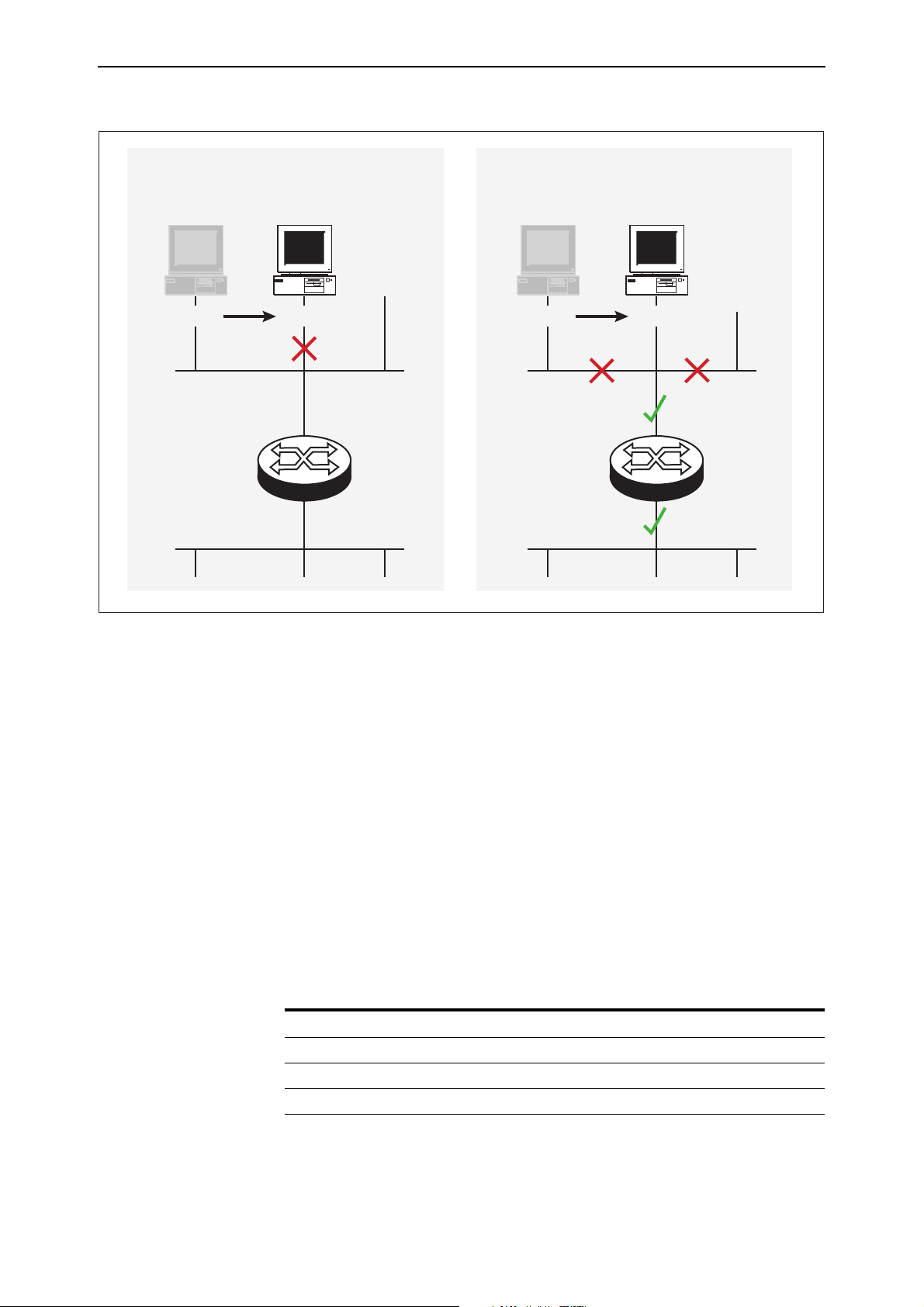
the switch. The following figure shows a PC that has been moved from port 15
to port 16 to illustrate the effect.
Software Version 2.8.1
C613-10477-00 REV B
Page 31
Software Version 2.8.1 31
Default behaviour
(vlansecure enabled)
port 15 port 16
vlan2
vlan1
Securing only the VLAN
(vlansecure disabled)
port 15 port 16
vlan2
vlan1
swi-filter
Configuring vlansecure
To turn off the default behaviour, so that the filter prevents access to only the
current VLAN when you move the host, use the new command:
disable switch filter vlansecure
To return to the standard filter behaviour, use the new command:
enable switch filter vlansecure
To display which mode the filtering behaviour is in, use the existing command:
show switch filter
This command now displays the additional field VlanSecure, which is either
DISABLED or ENABLED.
Command Changes
The following table summarises the new and modified commands:
Command Change
disable switch filter vlansecure New command
enable switch filter vlansecure New command
show switch filter New VlanSecure field
Software Version 2.8.1
C613-10477-00 REV B
Page 32

32 Switching Enhancements Release Note
Change of Debug Command Syntax
This Software Version includes a change in syntax for the enable switch debug
and disable switch debug commands. To enable or disable debugging on the
switch chip operations, you now use the dev option. Previously, this type of
debugging was enabled or disabled using the m6 parameter. There is no
change in the style or type of debugging information displayed.
To enable debugging of the switch chip operations, use the command:
enable switch debug=dev [other options]
To disable debugging of the switch chip operations, use the command:
disable switch debug=dev
Command Changes
The following table summarises the modified commands:
Command Change
disable switch debug New dev option in debug parameter.
enable switch debug New dev option in debug parameter.
show switch debug New DEV option in output.
Enhanced Static Switch Filtering on Ports within a Trunk Group
This Software Version ensures that traffic flow is not interrupted when a port
within a trunk group goes link-down.
In previous Software Versions, when a port that is part of a trunk group goes
link-down, the router or switch drops any traffic that is forwarded by a static
switch filter out of that port.
In this Software Version, when a port that is part of a trunk group goes
link-down, the router or switch modifies any static switch filters defined to
forward traffic out of that port. It modifies the egress port for the switch filter
entry to a port which is link-up within the trunk group. This ensures that traffic
can flow without interruption despite the original port going link-down.
Command Changes
This expansion does not affect any commands.
Ethernet Protection Switching Ring (EPSR)
EPSR is a protection system employed to prevent loops and provide high
resiliency within Ethernet ring based topologies. It offers:
■ A rapid detection and recovery time (in the order of 50 ms, depending on
configuration) if a link or node fails.
■ A faster and more effective alternative to spanning tree based options
when creating resilient ring networks.
Information about EPSR and its commands is shown in the EPSR chapter.
Software Version 2.8.1
C613-10477-00 REV B
Page 33

Software Version 2.8.1 33
Command Reference Updates
This section describes each new command and the changed portions of
modified commands and output screens. For modified commands and output,
new parameters, options and fields are shown in bold.
create switch trunk
Syntax CREate SWItch TRunk=trunk [POrt=port-list]
[SPeed={10M|100M|1000M|10G}]
[THRASHAction={LEarndisable|LINKDown|NONE|POrtdisable|V
LANdisable}] [THRASHTimeout={None|1..86400}]
Description This command creates a trunk group on the switch and optionally adds ports
to the trunk group and sets port speed. must not be in another trunk group
The thrashaction parameter specifies the action the router or switch takes
when it detects MAC address thrashing on a trunk. Thrashing occurs when one
or more ports or trunks repeatedly learn the same MAC addresses, for
example, as a result of a network loop. The router or switch applies the trunk’s
thrashaction to all ports in the trunk.
Take care with the thrashaction parameter because misuse can impair your
network operation.
Set the thrashaction parameter to:
■ none to apply no thrash limiting on the trunk.
■ learndisable to disable MAC address learning on all ports in the thrashing
trunk, until the period specified with the thrashtimeout parameter has
elapsed. The default is learndisable.
■ portdisable or linkdown to disable all ports in the thrashing trunk until
either the period specified by the thrashtimeout parameter has elapsed, or
until the ports or subset of ports in the trunk are re-enabled by the enable
switch port command. If linkdown is specified, the link state is down; if
portdisable is specified, the link state remains up.
■ vlandisable to block all traffic on the VLAN where the address was
learned, on all ports in the thrashing trunk, until either the period specified
by thrashtimeout has elapsed, or until the ports are re-enabled using the
enable switch port vlan command. When thrashaction=vlandisable, there
is only one timer per trunk, so if multiple VLANs have been disabled on a
trunk, the timer starts when the last VLAN was disabled. When the timer
expires, all VLANs are re-enabled on the trunk. When
thrashaction=vlandisable, ingress filtering is automatically enabled on all
ports in the trunk.
Software Version 2.8.1
C613-10477-00 REV B
The thrashtimeout parameter specifies the time, in seconds, for which the
switch employs the thrash action specified by the thrashaction parameter. The
thrashtimeout cannot be set to none if thrashaction=learndisable. If
thrashtimeout=none, and thrashaction is then changed to learndisable, then
the router or switch automatically changes the thrashtimeout to 1 second.
If none is specified, the trunk is not automatically re-enabled, but individual
ports can be re-enabled by using the enable switch port command for
thrashaction=portdisable or linkdisable, and the enable switch port vlan
command for thrashaction=vlandisable. The default is 1 second.
Page 34

34 Switching Enhancements Release Note
disable switch debug
Syntax DISable SWItch DEBug={ARL|DEV|DMA|PHY|ALL}
Description The m6 parameter is now replaced by the dev parameter in this command.
Debug Option Description
DEV Debugging occurs on operations related to the switch chip.
disable switch filter vlansecure
Syntax DISable SWItch FILter VLANSecure
Description This new command modifies Layer 2 switch filtering by disabling vlansecure
mode. The vlansecure mode is enabled by default.
When vlansecure mode is disabled and a filter exists for a given host and port,
moving the host to a different port in the same VLAN only stops the host from
accessing that VLAN, not other VLANs. When vlansecure mode is enabled
and a filter exists for a given host and port, moving the host to a different port
blocks the host completely.
Example To turn off the default filtering behaviour, use the command:
dis swi fil vlan
disable switch port vlan
Syntax DISable SWItch POrt={port-list|ALL}
VLAN[={vlan-name|1..4094|ALL}]
where:
■ port-list is a port number, range (specified as n-m), or comma-separated list
of numbers and/or ranges. Port numbers start at 1 and end at m, where m
is the highest numbered Ethernet switch port, including uplink ports.
■ vlan-name is a unique name from 1 to 32 characters. Valid characters are
uppercase and lowercase letters, digits, the underscore, and hyphen.
Description This new command disables one or more ports from VLANs to which they
belong. Once disabled, a port remains a member of the VLAN, but does not
receive or transmit packets from that VLAN.
The port parameter specifies the port or ports to disable. If a trunked port is
specified, all ports in the trunk are disabled. When a VLAN is disabled on a
port, ingress filtering is automatically enabled for that port
The vlan parameter specifies the VLAN or VLANs for which ports are
disabled. Specified ports must be a member of the VLAN. If no value, or all is
specified, the specified ports will be disabled for all VLANs to which they
belong.
Software Version 2.8.1
C613-10477-00 REV B
Page 35

Software Version 2.8.1 35
Example To disable the default vlan on port 1, use the command:
dis swi po=1 vlan=1
enable switch debug
Syntax ENAble SWItch DEBug={ARL|DEV|DMA|PHY|ALL} [OUTPUT=CONSOLE]
[TIMEOUT={1..4000000000|NONE}]
Description The m6 parameter is now replaced by the dev parameter in this command.
Debug Option Description
DEV Debugging is disabled for operations related to the switch chip.
enable switch filter vlansecure
Syntax ENAble SWItch FILter VLANSecure
Description This new command returns Layer 2 switch filtering to its default behaviour by
enabling vlansecure mode. The vlansecure mode is enabled by default.
When vlansecure mode is enabled and a filter exists for a given host and port,
moving the host to a different port blocks the host completely. When
vlansecure mode is disabled and a filter exists for a given host and port,
moving the host to a different port in the same VLAN only stops the host from
accessing that VLAN, not other VLANs.
Example To turn on the default filtering behaviour, use the command:
ena swi fil vlan
enable switch port vlan
Syntax ENAble SWItch POrt={port-list|ALL}
VLAN[={vlan-name|1..4094|ALL}]
where:
■ port-list is a port number, range (specified as n-m), or comma-separated list
of numbers and/or ranges. Port numbers start at 1 and end at m, where m
is the highest numbered Ethernet switch port, including uplink ports.
Software Version 2.8.1
C613-10477-00 REV B
■ vlan-name is a unique name from 1 to 32 characters. Valid characters are
uppercase and lowercase letters, digits, the underscore, and hyphen.
Description This new command enables one or more ports for VLANs to which they
belong. A port is automatically enabled for a VLAN when it is added to that
VLAN, however, it can be disabled using the disable switch port vlan
command, or automatically disabled by thrash limiting or QoS protection.
The port parameter specifies the port or ports to enable. If a trunked port is
specified, all ports in the trunk are enabled.
Page 36

36 Switching Enhancements Release Note
The vlan parameter specifies the VLAN or VLANs for which ports are enabled.
Specified ports must be a member of the VLAN. If no value or all is specified,
the specified ports are enabled for all VLANs to which they belong.
Note that when a disabled VLAN is re-enabled on a port, the port
automatically has ingress filtering disabled, as long as there are no other
VLANs disabled on the port, and as long as ingress filtering was not previously
enabled by using the set switch port command.
Example To enable the default vlan on port 1, use the command:
ena swi po=1 vlan=1
set lacp
Syntax SET LACP PRIOrity=priority
[THRASHAction={LEarndisable|LINkdown|NONE|POrtdisable|V
LANdisable}] [THRASHTimeout={None|1..86400}]
Description This command modifies the LACP parameters.
The thrashaction parameter specifies the action the router or switch takes
when it detects MAC address thrashing on any trunk created by LACP.
Thrashing occurs when one or more ports or trunks repeatedly learn the same
MAC addresses, for example, as a result of a network loop. The router or
switch applies the trunk’s thrashaction to all ports in the trunk.
Take care with the thrashaction parameter because misuse can impair your
network operation.
Set the thrashaction parameter to:
■ none to apply no thrash limiting on the trunk.
■ learndisable to disable MAC address learning on all ports in the thrashing
trunk, until the period specified with the thrashtimeout parameter has
elapsed. The default is learndisable.
■ portdisable or linkdown to disable all ports in the thrashing trunk until
either the period specified by the thrashtimeout parameter has elapsed, or
until the ports or subset of ports in the trunk are re-enabled by the enable
switch port command. If you specify linkdown, the link state is down; if
you specify portdisable, the link state remains up.
■ vlandisable to block all traffic on the VLAN where the address was
learned, on all ports in the thrashing trunk, until either the period specified
by thrashtimeout has elapsed, or until the ports are re-enabled using the
enable switch port vlan command. When thrashaction=vlandisable, there
is only one timer per trunk, so if multiple VLANs have been disabled on a
trunk, the timer starts when the last VLAN was disabled. When the timer
expires, all VLANs are re-enabled on the trunk. When
thrashaction=vlandisable, ingress filtering is automatically enabled on all
ports in the trunk.
The thrashtimeout parameter specifies the time, in seconds, for which the
switch employs the thrash action specified by the thrashaction parameter. The
thrashtimeout cannot be set to none if thrashaction=learndisable. If
thrashtimeout=none, and thrashaction is then changed to learndisable, then
the router or switch automatically changes the thrashtimeout to 1 second.
Software Version 2.8.1
C613-10477-00 REV B
Page 37

Software Version 2.8.1 37
If none is specified, the trunk is not automatically re-enabled, but individual
ports can be re-enabled by using the enable switch port command for
thrashaction=portdisable or linkdisable, and the enable switch port vlan
command for thrashaction=vlandisable. The default is 1 second.
set switch hwfilter mode
Syntax SET SWItch HWFilter MODe={PSF|NPSF}
Description This new command changes the router or switch’s classifier-based packet filter
mode, and is only valid for models with 48 ports (two switch instances). Use
this command to ensure that packets are filtered as expected on 48-port routers
or switches.
You can change the hardware filter mode after filters have been entered. When
you change modes, the filter entries remain in the original order.
The mode parameter specifies the filtering mode the router or switch is set in.
The default mode is psf.
When you specify psf, the router or switch expects port-specific filters to be
entered first. Use this mode when you want non port-specific filters to override
the port-specific filters for certain circumstances. If you add a port-specific
filter after the non port-specific filters, the router or switch may still use a
matching non port-specific filter when the packet travels between ports on
different switch instances.
When you specify npsf, the router or switch expects non port-specific filters to
be entered first. Use this mode when you want port-specific filters to override
the non port-specific filters for certain circumstances. If you add a non
port-specific filter after the port-specific filters, the router or switch may not
use the port-specific filter when the packet travels between ports on different
switch instances.
Example To set the hardware filter mode to non port-specific filters first, use the
command:
set swi hwf mod=npsf
set switch hwrouteupdate
Syntax SET SWItch HWRouteupdate=1..maximum
Software Version 2.8.1
C613-10477-00 REV B
Description This new command sets the length of the hardware route update queue.
The hwrouteupdate parameter specifies the maximum possible number of
entries in the queue. The maximum and default values depend on the amount of
memory on the switch, as shown in the following table:
Memory Size (Mbytes) Default length
(number of entries)
up to 128 200000 200000
129-256 1000000 1500000
more than 256 3000000 4000000
Maximum possible length
(number of entries)
Page 38

38 Switching Enhancements Release Note
Example To make the queue as long as possible on a switch with 256Mbytes of memory,
use the command:
set swi hwr=4000000
set switch port
SET SWItch POrt={port-list|ALL} [ACCeptable={ALL|VLAN}]
[BCLimit={NONE|limit] [DESCription=[description]]
[EGResslimit={bandwidth|DEFault}]
[IGMPACtion={DENY|REPlace}]
[IGMPFIlter={NONE|filter-id}]
[IGMPMAxgroup={NONE|1..65535}] [INFILTering={OFF|ON}]
[INTRusionaction={DISAble|DIScard|TRap}]
[LEARn={NONE|0|1..256] [MIRRor={BOTH|NONE|RX|TX}]
[MODe={AUTOnegotiate|MASTer|SLAve}]
[POLarity={MDI|MDIX}] [RELearn={OFF|ON}]
[SPeed={AUTOnegotiate|10MAUTo|10MHALf|10MFUll|10MHAUto|
10MFAuto|100MAUto|100MHALf|100MFUll|100MHAUto|100MFAuto
|1000MHALf|1000MFUll|1000MFAUto}]
[THRASHAction={LEarndisable|LINKDown|NONE|POrtdisable|V
LANdisable}] [THRASHTimeout={None|1..86400}]
[VLANSTAtustrap={ON|OFF}]
Description This command modifies the value of parameters for switch ports.
The description parameter can now be entered without a value, to remove an
existing description.
The thrashaction parameter specifies the action the router or switch takes
when it detects MAC address thrashing on a port. Thrashing occurs when one
or more ports repeatedly learn the same MAC addresses, for example, as a
result of a network loop.
Take care with the thrashaction parameter because misuse can impair your
network operation.
Set the thrashaction parameter to:
■ none to apply no thrash limiting to the port.
■ learndisable to disable MAC address learning on the port, until the period
specified with the thrashtimeout parameter has elapsed. The default is
learndisable.
■ portdisable or linkdown to disable the port until either the period
specified by the thrashtimeout parameter has elapsed, or until the port is
re-enabled by using the enable switch port command. If you specify
linkdown, the link state is down; if you specify portdisable, the link state
remains up.
■ vlandisable to block all traffic on the VLAN where the address was
learned, until either the period specified by thrashtimeout has elapsed, or
until the port is re-enabled by using the enable switch port vlan
command.
The thrashtimeout parameter specifies the time, in seconds, for which the
switch employs the thrash action specified by the thrashaction parameter. The
thrashtimeout cannot be set to none if thrashaction=learndisable. If
Software Version 2.8.1
C613-10477-00 REV B
Page 39

Software Version 2.8.1 39
thrashtimeout=none, and thrashaction is then changed to learndisable, then
the router or switch automatically changes the thrashtimeout to 1 second.
If none is specified, the port is not automatically re-enabled, but can be
re-enabled by using the enable switch port command for
thrashaction=portdisable or linkdisable, and the enable switch port vlan
command for thrashaction=vlandisable. The default is 1 second.
The vlanstatustrap parameter specifies whether the switch will send an SNMP
trap whenever a port is enabled or disabled for a VLAN. A port can be disabled
for a VLAN by using the disable switch port command, either when thrashing
is detected on a port and the port’s thrashaction is vlandisable, or when a
storm is detected by QoS storm protection and the stormaction is vlandisable.
If on is specified, a trap is sent. If off is specified, a trap is not sent. The default
is off.
set switch thrashlimit
Syntax SET SWItch THRASHLimit=5..255
Description This new command sets the maximum number of times a MAC address can
move between ports, in one second. When the specified limit is reached, the
thrashaction specifed with the set switch port command is applied. The
default thrashlimit is 10.
Example To set the switch thrash limit to 100 MAC movements per second, use the
command:
set swi thrashl=100
set switch trunk
Syntax SET SWItch TRunk=trunk [SPeed={10M|100M|1000M|10G}]
[THRASHAction={LEarndisable|LINKDown|NONE|POrtdisable|
VLANdisable}] [THRASHTimeout={None|1..86400}]
Description This command sets the speed for a specific trunk group on the switch. The
switch supports static 802.3ad link aggregation, and port trunking is also called
link aggregation.
The thrashaction parameter specifies the action the router or switch takes
when it detects MAC address thrashing on a trunk. Thrashing occurs when one
or more ports or trunks repeatedly learn the same MAC addresses, for
example, as a result of a network loop. The router or switch applies the trunk’s
thrashaction to all ports in the trunk.
Software Version 2.8.1
C613-10477-00 REV B
Take care with the thrashaction parameter because misuse can impair your
network operation.
Set the thrashaction parameter to:
■ none to apply no thrash limiting on the trunk.
■ learndisable to disable MAC address learning on all ports in the thrashing
trunk, until the period specified with the thrashtimeout parameter has
elapsed. The default is learndisable.
Page 40

40 Switching Enhancements Release Note
■ portdisable or linkdown to disable all ports in the thrashing trunk until
either the period specified by the thrashtimeout parameter has elapsed, or
until the ports or subset of ports in the trunk are re-enabled by the enable
switch port command. If you specify linkdown, the link state is down; if
you specify portdisable, the link state remains up.
■ vlandisable to block all traffic on the VLAN where the address was
learned, on all ports in the thrashing trunk, until either the period specified
by thrashtimeout has elapsed, or until the ports are re-enabled using the
enable switch port vlan command. When thrashaction=vlandisable, there
is only one timer per trunk, so if multiple VLANs have been disabled on a
trunk, the timer starts when the last VLAN was disabled. When the timer
expires, all VLANs are re-enabled on the trunk. When
thrashaction=vlandisable, ingress filtering is automatically enabled on all
ports in the trunk.
The thrashtimeout parameter specifies the time, in seconds, for which the
switch employs the thrash action specified by the thrashaction parameter. The
thrashtimeout cannot be set to none if thrashaction=learndisable. If
thrashtimeout=none, and thrashaction is then changed to learndisable, then
the router or switch automatically changes the thrashtimeout to 1 second.
If none is specified, the trunk is not automatically re-enabled, but individual
ports can be re-enabled by using the enable switch port command for
thrashaction=portdisable or linkdisable, and the enable switch port vlan
command for thrashaction=vlandisable. The default is 1 second.
show lacp
Syntax SHow LACP
Description This command displays the state of LACP on the router or switch.
Table 3: Example output from the show lacp command
LACP Information
------------------------------------------------------------
Status .......................... Enabled
Actor System Priority ........... 80-00
Actor System .................... 00-3e-0a-12-00-01
Address learn thrash action ..... Learn Disable
Address learn thrash timeout .... 1 second
LACP Ports ...................... 1-3,5,7,9-12
Active ........................ 1-3,5
Passive ....................... 7,9-12
Software Version 2.8.1
C613-10477-00 REV B
Page 41

Software Version 2.8.1 41
Table 4: New parameters in output of the show lacp command
Parameter Description
Address learn thrash
action
Address learn thrash
timeout
The thrashaction value that is applied to any trunks created by
LACP. This specifies the action the router or switch takes when the
address learn thrash limit is exceeded on the trunk.
Disable Learning Learning is disabled on all ports in the trunk
Disable Port All ports in the trunk are disabled but the links
will remain up
Link Down All ports in the trunk are disabled and the links
will go down
Disable Vlan All ports in the trunk are disabled for the
VLAN that thrashing occurring on.
The thrashtimeout value to apply to any trunks created by LACP. It
specifies the time, in seconds, for which a trunk remains disabled
after being disabled by thrashing protection.
If ‘None’ is shown, the trunk remains disabled until manually
re-enabled.
show switch
Syntax SHow SWItch
Description This command now shows information about the hardware route update
queue (Figure 5, Figure 6, Table 5).
Figure 5: New parameters in output of the show switch command when hardware
learning delay is disabled
Switch Configuration
-----------------------------------------------------------
Switch Address ............. 00-00-cd-12-78-03
Learning ................... ON
Ageing Timer ............... ON
IP route:
Learn delay ............. OFF
queue limit ....... 1000000
queue maximum ..... 1500000
queue default ..... 1000000
Updating hardware(status) 0 (Pending)
.
.
.
Software Version 2.8.1
C613-10477-00 REV B
Page 42

42 Switching Enhancements Release Note
Figure 6: New parameters in output of the show switch command when hardware
learning delay is enabled
Switch Configuration
-----------------------------------------------------------
Switch Address ............. 00-00-cd-12-78-03
Learning ................... ON
Ageing Timer ............... ON
IP route:
Learn delay ............. 4 ms
queue size ........ 0
queue limit ....... 1000000
percent in use .... 0
high water mark ... 0
queue maximum ..... 1500000
queue default ..... 1000000
Updating hardware(status) 0 (Pending)
.
.
.
Software Version 2.8.1
C613-10477-00 REV B
Page 43

Software Version 2.8.1 43
Table 5: New parameters in the output of the show switch command
Parameter Meaning
Learn delay Number of milliseconds that the switch waits after the last IP
route is inserted before it starts to update the hardware
routing system.
Queue size The number of entries currently in the hardware route update
queue.
Queue limit The maximum number of entries that the queue can hold.
Percent in use The percentage of the queue limit that is currently used.
High water mark The highest number of messages that have been seen on the
queue since the switch last started up.
Queue maximum The maximum value to which you can set the queue size. This
depends on the amount of memory installed on the switch.
Queue default The default maximum number of entries in the queue. This
depends on the amount of memory installed on the switch.
Updating hardware (status) The number of entries that the software has queued for
writing into the hardware table, followed by the status. Status
is Pending if the hardware is not currently processing queued
routes and Active if it is currently processing the routes.
show switch debug
Syntax SHow SWItch DEBug
Figure 7: Example output from the show switch debug command
Enabled Switch Debug Modes Output Timeout
---------------------------------------------------------DEV 16 12345
----------------------------------------------------------
Table 6: Parameters in output of the show switch debug command
Parameter Meaning
Enabled Switch Debug Modes Whether the debugging option for the router or switch is
ARL, DMA, DEV, PHY, or None.
Software Version 2.8.1
C613-10477-00 REV B
Page 44

44 Switching Enhancements Release Note
show switch filter
Syntax SHow SWItch FILter [POrt={port-list|ALL}]
[ACtion={FORward|DIScard}] [DESTaddress=macadd]
[ENTry=entry-list] [VLAN={vlan-name|1..4094}]
Description This command displays information about Layer 2 switch filters.
Figure 8: Example output from the show switch filter command
Switch Filters
---------------------------------------------------------------------------
VlanSecure ................ ENABLED
Entry VLAN Destination Address Port Action Source
-------------------------------------------------------------------------- 0 default (1) aa-ab-cd-00-00-01 1 Forward static
1 default (1) aa-ab-cd-00-00-02 1 Forward static
0 marketing (2) aa-ab-cd-00-00-01 2 Discard static
1 marketing (2) aa-ab-cd-00-00-02 2 Discard learn
---------------------------------------------------------------------------
Table 7: New parameter in output of the show switch filter command
Parameter Meaning
VlanSecure Whether vlansecure mode is ENABLED or DISABLED.
Standard filtering behaviour is ENABLED.
show switch hwfilter
Syntax SHow SWItch HWFilter [CLASSifier=classifier-list]
Description This command displays information about the configuration of hardware
filtering on the router or switch, and a summary of the current filters.
Figure 9: Modified example output from the show switch hwfilter command
Switch Hardware Filter Summary Information
------------------------------------------------------------
Number of Filters .... 12
Status ............... ENABLED
Mode ................. NPSF
Filter ............... 1
Classifier ........... 3
Filter ............... 2
Classifier ........... 100
Filter ............... 3
Classifier ........... 101
------------------------------------------------------------
Software Version 2.8.1
C613-10477-00 REV B
Page 45

Software Version 2.8.1 45
Table 8: Modified parameters in output of the show switch hwfilter command
Parameter Meaning
Mode Whether the router or switch expects hardware filters to be ordered
with port-specific filters first (“PSF”), or non port-specific filters first
(“NPSF”). This only displays for models with 48 ports (two switch
instances).
show switch port
Syntax SHow SWItch POrt[={port-list|ALL}]
Description This command displays general information about all ports or a specific one.
Figure 10: Example output from the show switch port command for port-based VLANs
Switch Port Information
------------------------------------------------------------
Port .......................... 49
Description ................... To intranet hub, port 49
Status ........................ ENABLED
Link State .................... Up
UpTime ........................ 02:35:26
Port Media Type ............... ISO8802-3 CSMACD
Configured speed/duplex ....... Autonegotiate
Actual speed/duplex ........... 1000 Mbps, full duplex
MDI Configuration (Polarity) .. Manual (MDI)
Loopback ...................... Off
Configured master/slave mode .. Not applicable
Actual master/slave mode ...... Not applicable
Acceptable Frames Type ........ Admit All Frames
Disabled egress queues ........ Q0, Q3-4
BCast & MCast rate limit ...... 400 Kbytes\sec
BCSC rate Limiting ............ Broadcast and Multicast enabled
Egress rate limit ............. 10240 K/bs
Learn limit ................... -
Intrusion action .............. Discard
Current learned, lock state ... 0, locked by thrashing
Address learn thrash status ....Thrashing
Address learn thrash action ... Disable Learning
Address learn thrash timeout .. 1 second
VLAN Status Trap .............. OFF
.
.
.
Software Version 2.8.1
C613-10477-00 REV B
Table 9: New parameters in output of the show switch port command
Parameter Meaning
Port Number of the switch port.
Page 46

46 Switching Enhancements Release Note
Table 9: New parameters in output of the show switch port command (cont.)
Parameter Meaning
Address learn thrash
status
The thrashing protection status of the port. If the thrash action is
set to vlandisable, the status is shown for each VLAN that the
port is a member of, with each VLAN listed on a separate line.
Not Detected Thrashing has not been detected on the port.
Thrashing Thrashing has been detected and the specified
thrash action has been applied.
Disabled Thrashing protection is disabled because the
thrashaction is set to none.
Trunked The port is trunked and therefore thrashing
protection is controlled by the trunk.
Address learn thrash
action
Action taken when the address learn thrash limit is exceeded:
Disable Learning Address learning on the port is temporarily
disabled.
Disable Port The port is disabled, but the link remains up.
Link Down The port is disabled, and the link is down.
Disable VLAN The port is disabled for the VLAN on which
thrashing is occurring.
Address learn thrash
timeout
The time, in seconds for which a port remains disabled after being
disabled by thrashing protection. When a timeout value is
specified and the port is currently disabled by the thrash limit, the
time remaining before the port is re-enabled is shown in
parentheses.
None The port remains disabled until manually
re-enabled.
VLAN Status Trap Whether an SNMP trap is sent when a port is enabled or disabled
for the VLAN. Either on or off.
Software Version 2.8.1
C613-10477-00 REV B
Page 47

Software Version 2.8.1 47
PPPoE Access Concentrator
This release introduces the ability for the PPPoE Access Concentrator and a
PPPoE Client to be active simultaneously. You can now specify the interface to
which the PPPoE Access Concentrator should attach.
Command Changes
The following table summarises the modified commands:
Command Change
add ppp acservice New acinterface parameter to supercede the now
deprecated vlan parameter.
delete ppp acservice New acinterface parameter to supercede the now
deprecated vlan parameter.
set ppp acservice New acinterface parameter to supercede the now
deprecated vlan parameter.
show ppp pppoe New description for the interface parameter.
Command Reference Updates
This section describes the changed portions of modified commands and output
screens. The new parameters and options are shown in bold for modified
commands.
add ppp acservice
Syntax ADD PPP ACSERVICE=service-name TEMPLATE=ppp-template
[ACRADIUS={OFF|ON}] [MAXSESSIONS=1..512]
[ACINTerface={NONE|interface}]
where:
■ interface is an interface name formed by concatenating an interface type
and an interface instance (e.g. eth0). Valid interface types are ETH and
VLAN.
Description This command adds a new PPP over Ethernet Access Concentrator service to
the router or switch. PPPoE hosts are able to connect to the router or switch
using this service.
To allow a PPPoE host to be defined on the router or switch as well as on an
Access Concentrator service, the acinterface parameter must be used. The
acinterface parameter specifies the interface to be used by the Access
Concentrator service. If none is specified, the Access Concentrator service uses
all valid interfaces. A service can be offered on several interfaces, but it is
necessary to issue one add ppp acservice command for each interface. For
example:
add ppp acservice=bob template=1 acint=eth0
add ppp acservice=bob template=1 acint=vlan5
Software Version 2.8.1
C613-10477-00 REV B
To offer the service on all the Ethernet interfaces only, there is no need to use
the acinterface parameter, as it defaults to none.
The acinterface parameter supercedes the now deprecated vlan parameter in
this command.
Page 48

48 PPPoE Access Concentrator Release Note
delete ppp acservice
Syntax DELete PPP ACservice=service-name
[ACINTerface={NONE|interface}]
where:
■ interface is an interface name formed by concatenating an interface type
and an interface instance (e.g. eth0). Valid interface types are ETH and
VLAN.
Description This command deletes a PPP over Ethernet Access Concentrator service from
the router or switch. Note that it is not possible to delete a service that is
currently in use.
The acinterface parameter specifies the interface on which the service is
offered. This parameter is used to further identify the service to delete, as it is
possible to have two or more services with the same name, but which are
offered on different interfaces:
■ If you specify an interface, it is on that interface that the service with the
specified name is deleted.
■ If you specify none, the service offered on the Ethernet port is deleted if it
was added with acinterface=none specified in the add ppp acservice
command.
If multiple interfaces exist for the service, you are prompted to specify an
acinterface. The default is none.
The acinterface parameter supercedes the now deprecated vlan parameter in
this command.
set ppp acservice
Syntax SET PPP ACservice=service-name [ACRadius={OFF|ON}]
[MAXSessions=1...512] [TEMPlate=ppp-template]
[ACINTerface={NONE|interface}]
Where:
■ interface is an interface name formed by concatenating an interface type
and an interface instance (e.g. eth0). Valid interface types are ETH and
VLAN.
Description This command sets the parameters associated with the specified PPPoE Access
Concentrator service.
The acinterface parameter specifies the interface on which the service is
offered. This parameter further identifies the service whose parameters are to
be changed, as it is possible to have two or more services with the same name
but offered on different interfaces. It is not possible to change the interface on
which the service is offered.
■ If an interface is specified, the service with the specified name on that
interface has its parameters changed.
■ If none is specified, the service offered on the Ethernet ports has its
parameters changed.
Software Version 2.8.1
C613-10477-00 REV B
Page 49

Software Version 2.8.1 49
■ If the acinterface parameter is omitted, the service is mapped to its
corresponding interface (if one exists).
If multiple interfaces exist for the service, you are asked to specify an
acinterface. The default for this parameter is none.
The acinterface parameter supercedes the now deprecated vlan parameter in
this command.
show ppp pppoe
Syntax SHow PPP PPPOE
Description This command displays information about PPPoE interfaces and services that
are currently configured.
Figure 11: Example output from the show ppp pppoe command
PPPOE
-----------------------------------------------------------PPP1:
Service Name ................. bob
Peer Mac Address ............. 00-00-cd-00-ab-a3
Interface .................... eth0
Session ID ................... a1a3
Maximum Segment Size ......... 1292
Access Concentrator Mode ..... Enabled
Services:
bob
Max sessions ................ 2
Current Sessions ............ 1
Template .................... 1
Interface ................... eth1
MAC RADIUS Authentication ... YES
carol
Max sessions ................ 5
Current Sessions ............ 0
Template .................... 1
Interface ................... vlan1
MAC RADIUS Authentication ... YES
PPPOE Counters:
Rejected PADI packets ...... 0
Rejected PADO packets ...... 0
Rejected PADR packets ...... 0
Rejected PADS packets ...... 0
Rejected PADT packets ...... 0
-----------------------------------------------------------
Table 10: New parameter in output of the show ppp pppoe command
Software Version 2.8.1
C613-10477-00 REV B
Parameter Meaning
Interface The interface that the PPPoE Access Concentrator or
PPPoE Client is using. If all Ethernet interfaces are being
used, “ethernet" will be displayed.
Page 50

50 MSTP Enhancement Release Note
MSTP Enhancement
Two new commands have been added to simplify MSTP operation.
Command Changes
The following table summarises the new commands:
Command Change
disable mstp port New command
enable mstp port New command
Command Reference Updates
This section describes each new command.
disable mstp port
Syntax DISable MSTP POrt={port-list|ALL}
where:
■ port-list is a port number, range (specified as n-m), or comma-separated list
of port numbers and/or ranges. Port numbers start at 1 and end at m,
where m is the highest numbered Ethernet switch port, including uplink
ports.
Description This new command disables the Multiple Spanning Tree algorithm on the
specified ports, or all ports, for both the CIST and all currently configured
MSTIs. This command offers a shorter alternative to using the disable mstp
cist port command, followed by the disable mstp msti port command.
Example To disable the CIST and all MSTIs on ports 10-15, use the command:
dis mstp po=10-15
enable mstp port
Syntax ENAble MSTP POrt={port-list|ALL}
where:
■ port-list is a port number, range (specified as n-m), or comma-separated list
of port numbers and/or ranges. Port numbers start at 1 and end at m,
where m is the highest numbered Ethernet switch port, including uplink
ports.
Description This new command enables operation of the Multiple Spanning Tree algorithm
on the specified ports, or all ports, for the both the CIST and all currently
configured MSTIs. This command offers a shorter alternative to using the
enable mstp cist port, command, followed by the enable mstp msti port
commands.
Example To enable the CIST and all MSTIs on ports 10-15, use the command:
ena mstp po=10-15
Software Version 2.8.1
C613-10477-00 REV B
Page 51

Software Version 2.8.1 51
STP Enhancement
You can now display the RSTP states for one or more ports by using the
existing command:
show stp port={port-list|all} rstpstate
The information for each port now starts with the port number. This makes the
output more readable.
Command Changes
The following table summarises the modified command:
Command Change
show stp port New Port field in output
Command Reference Updates
This section describes the changed portions of modified commands and output
screens. For modified commands and output, the new parameters, options,
and fields are shown in bold.
show stp port
Syntax SHow STP[={stp-name|ALL}] POrt={port-list|ALL} RSTPstate
Description The output of this command includes a new field.
Figure 12: Example output from the show stp port rstpstate command
RSTP State Information
-------------------------------------------------------------------------- STP Name: default
Bridge Level State Machine ............ STATE
Port Role Selection ................. Role Selection
Port .................................. 1
Port State Machines ................. STATE
Port Information .................... Disabled
Port Role Transitions ............... Blocked Port
Port State Transition ............... Discarding
Topology Change ..................... Inactive
Port Protocol Migration ............. Init
Port Transmit ....................... Idle
Port .................................. 2
Port State Machines ................. STATE
Port Information .................... Disabled
Port Role Transitions ............... Blocked Port
Port State Transition ............... Discarding
Topology Change ..................... Inactive
Port Protocol Migration ............. Init
Port Transmit ....................... Idle
.
.
.
Software Version 2.8.1
C613-10477-00 REV B
Table 11: New parameters in the output of the show stp port rstpstate command
Parameter Meaning
Port The number of the port for which state information is displayed.
Page 52

52 Asynchronous Port Enhancement Release Note
Asynchronous Port Enhancement
This section describes the enhancement. The modified commands to
implement it are described in Command Reference Updates.
Making Asynchronous Ports Respond More Quickly
When an asynchronous port is in ten mode, it bundles together the characters
that it receives within a certain time period, instead of passing them one at a
time to a higher protocol layer for processing. The time period over which
characters are bundled is set by the ten timer.
Bundling reduces the load on the CPU by spreading the character processing
overhead across several characters. If a remote terminal session is involved,
bundling also reduces the number of packets on the network by sending more
characters in each packet. However, bundling reduces terminal responsiveness.
A ten timer value of 100 milliseconds is generally a good compromise between
responsiveness and processing overhead. If you need to increase the port’s
responsiveness, this enhancement enables you to reduce the length of the ten
timer. To do this, use the new tentimervalue parameter in the set asyn
command:
set asyn[=port-number] [tentimervalue=20..100] [other optional
parameters]
Unless you are logged in via the port you want to change, also specify the
asynchronous port number.
The default tentimervalue value is 100 milliseconds, which is the value it had
before this enhancement.
To display a port’s value for the ten timer, use the command:
show asyn=port-number
In the output, check the new Ten timer value field. Note that the Mode field
displays Te n if the asynchronous port is a terminal server port in ten mode.
Command Changes
The following table summarises the modified commands:
Command Change
set asyn New tentimervalue parameter
show asyn New Ten timer value field
Software Version 2.8.1
C613-10477-00 REV B
Page 53

Software Version 2.8.1 53
Command Reference Updates
This section describes the changed portions of modified commands and output
screens. For modified commands and output, the new parameters, options,
and fields are shown in bold.
set asyn
Syntax SET ASYn[=asyn-number] [ATtention={Break|alphabetical
control char|^[|None}]
[CDcontrol={Connect|Ignore|Online}]
[DAtabits={5|6|7|8}]
[DEFaultservice={ON|OFf|YES|NO|True|False}]
[DTrcontrol={Connect|OFf|ON}]
[Echo={ON|OFF|YES|NO|True|False}] [ENable={BREAK|NONE}]
[Flow={Character|HArdware|None}] [History=0..99]
[IDLEtimeout={10..4294967294|OFF|0}]
[INFlow={Character|HAreware|None}]
[IPaddress={ipadd|NONe}] [IPXnetwork=network]
[LOGin={ON|OFf|YES|NO|True|False}]
[MAXoqlen=0..4294967295] [MTu=40..1500] [NAme=name]
[OUTFlow={Character|HArdware|None}] [PAGe={0..99|OFF}]
[PARity={Even|Mark|None|Odd|SPace}]
[PRompt={prompt|DEFault|OFf}]
[SECure={ON|OFf|YES|NO|True|False}]
[SERvice={service-name|None}]
[SPeed={AUTO|75|110|134.5|150|300|600|1200|1800|2000|24
00|4800|9600|14400|14.4K|19200|19.2K|28800|28.8K|38400|
38.4K|57600|57.6K|115200|115.2K}] [STopbits={1|2}]
[TENtimervalue=20..100] [TIMeout=1..65535]
[TYpe={Dumb|VT100}]
Description The new tentimervalue parameter sets the length of the ten timer, in
milliseconds. Reducing the length of the ten timer increases the port’s
responsiveness (see “Making Asynchronous Ports Respond More Quickly” on
page 52). Unless you are logged in via the port you want to change, also specify
the asynchronous port number. The default tentimervalue is 100.
show asyn
Syntax SHow ASYn[=port-number|ALL]
[{COUnters[={Diagnostic|INTerface|Rs232}]|History|
Summary}]
Description When you specify asyn=por t-number or asyn=all, the output of this command
now includes a new field (Figure 13, Tabl e 12).
Software Version 2.8.1
C613-10477-00 REV B
Page 54

54 Asynchronous Port Enhancement Release Note
Figure 13: Example output from the show asyn=port-number command
ASYN 0 : 0003896346 seconds Last change at: 0000000000 seconds
ASYN information
Name ...................... Asyn 0
Status .................... enabled
Mode ...................... Ten
Data rate ................. 9600
Parity .................... none
Data bits ................. 8
Stop bits ................. 1
Test mode ................. no
In flow state (mode) ...... on (Hardware)
Out flow state (mode) ..... off (Hardware)
Autobaud mode ............. disabled
Max tx queue length ....... 16
TX queue length ........... 3
Transmit frame ............ none
RX queue length ........... 0
IP address ................ none
Max transmission unit ..... 1500
Ten timer value ........... 100
.
.
.
Table 12: New parameters in the output of the show asyn=port-number command
Parameter Meaning
Ten timer value The length of the ten timer, in milliseconds. When an asynchronous port
is in ten mode, it bundles together the characters that it receives within
a certain time period, instead of passing them one at a time to a higher
protocol layer for processing. The ten timer sets the time period over
which characters are bundled.
Software Version 2.8.1
C613-10477-00 REV B
Page 55

Software Version 2.8.1 55
Internet Group Management Protocol (IGMP) Enhancements
This Software Version includes the following enhancements to IGMP:
■ IGMP Proxy on x900 Series Switches
■ IGMP filtering extended to all IGMP message types
■ Monitoring reception of IGMP general query messages
This section describes the enhancements. The new and modified commands to
implement them are described in Command Reference Updates.
IGMP Proxy on x900 Series Switches
IGMP proxy was previously released on the following products:
■ AR400 Series routers
■ AR700 Series routers
■ AT-8600 Series switches
■ AT-8700XL Series switches
■ AT-8800 Series switches
■ Rapier Series switches
This software version adds support for IGMP proxy on the following x900
Series switches:
■ AT-8948
■ x900-48FE
■ x900-48FE-N
■ AT-9924T
■ AT-9924SP
■ AT-9924T/4SP
■ x900-24XT
■ x900-24XT-N
In a network with a simple tree topology, you can use IGMP proxy to simplify
the configuration of multicast routing. The router or switch at the root of the
tree must run a multicast routing protocol, but all other routers and switches in
the network can be configured as IGMP proxy agents.
Software Version 2.8.1
C613-10477-00 REV B
The IGMP proxy agent must be configured with a single upstream interface
and one or more downstream interfaces. An upstream interface is an interface
in the direction towards the root of the tree. A downstream interface is an
interface in the direction away from the root of the tree.
The IGMP proxy agent periodically transmits IGMP general membership
queries to the hosts attached to its downstream interfaces. The proxy agent
uses IGMP report and leave messages received on downstream interfaces to
build and maintain a database of multicast group memberships, and reports
changes to the list of multicast groups in the database on the upstream
Page 56

56 Internet Group Management Protocol (IGMP) Enhancements Release Note
interface. The following table summarises how the IGMP proxy agent
processes each IGMP message type.
When this message... Is received on this interface... Then the IGMP proxy agent...
Report downstream • adds the membership subscription to the multicast
group membership database
• forwards the report message on the upstream interface,
if the membership subscription is for a new multicast
group
upstream • discards the message without processing
Leave downstream • removes the membership subscription from the
multicast group membership database
• forwards the leave message on the upstream interface,
if there are no remaining membership subscriptions for
the multicast group (no other hosts connected to any of
the downstream interfaces have members of the
multicast group)
upstream • discards the message without processing
Group-specific query downstream • discards the message without processing
upstream • transmits a report message on the upstream interface,
if the multicast group membership database contains at
least one member of the multicast group attached to a
downstream interface
General query downstream • discards the message without processing
upstream • transmits a report message on the upstream interface
for each multicast group in the multicast group
membership database with at least one member
attached to a downstream interface
The IGMP proxy agent uses the information maintained in the multicast group
membership database to forward multicast data packets received on the
upstream interface to all downstream interfaces that have members of the
multicast group.
Multicast packet forwarding is enabled as long as:
■ a multicast routing protocol is not enabled
■ an interface is configured with IGMP proxy in the upstream direction
■ at least one interface is configured with IGMP proxy in the downstream
direction
To add an IP interface and configure IGMP proxying, use the command:
add ip interface=interface ipaddress={ipadd|dhcp}
[igmpproxy={off|upstream|downstream}] [other-options...]
To configure IGMP proxy on an existing IP interface, use the command:
set ip interface=interface
igmpproxy={off|upstream|downstream}]
IGMP proxy is turned off by default.
IGMP must also be enabled on the router or switch and on the interface for
IGMP proxy to function.
Software Version 2.8.1
C613-10477-00 REV B
Page 57

Software Version 2.8.1 57
To enable IGMP on the router or switch, use the command:
enable ip igmp
To enable IGMP on a specific interface, use the command:
enable ip igmp interface=interface
You can configure the IGMP proxy agent to monitor the reception of IGMP
general query messages on an interface, and to generate a log message and an
SNMP trap if an IGMP general query message is not received on the interface
within a specified time interval.
To enable monitoring on an interface and set the time interval, use the
command:
set ip igmp interface=interface
querytimeout={none|0|1..65535}
To display information about IGMP and the IGMP proxy agent, use the
command:
show ip igmp
Command Changes
The following table summarises the new and modified commands:
Command Change
add ip interface New igmpproxy parameter
set ip interface New igmpproxy parameter
set ip igmp interface New command
show ip igmp New IGMP Proxy field
IGMP filtering extended to all IGMP message types
IGMP filtering lets you manage the distribution of multicast services on each
switch port by controlling which multicast groups the hosts attached to a
switch port can join.
IGMP filtering is applied to multicast streams forwarded by IGMP, IGMP
Snooping, or MVR.
Filtering of IGMP membership reports was supported in a previous software
version. This software version adds support for filtering IGMP query, report
and leave messages.
Software Version 2.8.1
C613-10477-00 REV B
To configure an IGMP filter, you must create the filter and then apply it to one
or more switch ports.
To do this, first create the filter, using the command:
create igmp filter=filter-id
Then add one or more entries to the filter, using the command:
add igmp filter=filter-id groupaddress={ipadd|ipadd-ipadd}
[msgtype={query|report|leave}] [action={include|exclude}]
[entry=1..65535]
Page 58

58 Internet Group Management Protocol (IGMP) Enhancements Release Note
Finally, apply the filter to a switch port, using the command:
set switch port={port-list|all} igmpfilter=filter-id
[other-options...]
You can apply an IGMP filter to more than one switch port, but a single switch
port can have only one IGMP filter assigned to it.
To delete or modify an entry in a filter, use the commands:
delete igmp filter=filter-id entry=1..65535
set igmp filter=filter-id entry=1..65535
[groupaddress={ipadd|ipadd-ipadd}]
[msgtype={query|report|leave}] [action={include|exclude}]
To remove a filter from a switch port, use the command:
set switch port={port-list|all} igmpfilter=none
[other-options...]
To destroy a filter, first remove the filter from all ports that it is applied to, then
use the command:
destroy igmp filter=filter-id
To display information about IGMP filters, use the command:
show igmp filter=filter-id
To display the IGMP filter assigned to a switch port, use the command:
show switch port[={port-list|all}]
Command Changes
The following table summarises the modified commands:
Command Change
add igmp filter New msgtype parameter
set igmp filter New msgtype parameter
show igmp filter New fields Msg Type, Reports, Queries, and Leaves.
Software Version 2.8.1
C613-10477-00 REV B
Page 59

Software Version 2.8.1 59
Monitoring reception of IGMP general query messages
You can configure the IGMP proxy agent to monitor the reception of IGMP
general query messages on an interface. If an IGMP general query message is
not received on the interface within a specified time interval, IGMP generates
an igmpGeneralQueryNotReceivedEvent SNMP trap ({ enterprises(1)
alliedTelesyn(207) mibObject(8) brouterMib(4) atRouter(4) traps(2)
igmpTraps(1) 1 }) containing the ifName object for the interface, and the
following log message:
Message
Severity
Module
Log Type
Log Subtype
Recommended
Action
IGMP - No general query within time-interval
seconds on interface
5 / IMPORTANT
5 / IPG
021 / MSGS
002 / WARN
Check for connectivity between the device and the multicast router
acting as a Querier on the sub-network.
Check the current status of the Querier.
If the interface which generated the log message is not a
downstream multicasting port, use the set ip igmp interface
command to set the querytimeout to zero.
To enable monitoring on an interface and set the time interval, use the
command:
set ip igmp interface=interface
querytimeout={none|0|1..65535}
To display information about IGMP and the IGMP proxy agent, use the
command:
show ip igmp
Command Changes
The following table summarises the new and modified commands:
Command Change
set ip igmp interface New command
show ip igmp New General Query Reception Timeout field.
Software Version 2.8.1
C613-10477-00 REV B
Page 60

60 Internet Group Management Protocol (IGMP) Enhancements Release Note
Command Reference Updates
This section describes each new command and the changed portions of
modified commands and output screens. For modified commands and output,
the new parameters, options, and fields are shown in bold.
add igmp filter
Syntax ADD IGMP FILter=filter-id GROupaddress={ipadd|ipadd-ipadd}
[MSGType={QUEry|REPort|LEAVe}]
[ACtion={INCLude|EXCLude}] [ENTry=1..65535]
where:
■ filter-id is a decimal number from 1 to 99.
■ ipadd is an IP address in dotted decimal notation.
Description The new msgtype parameter specifies the type of incoming IGMP message to
match. If you specify query, the filter will match IGMP general and
group-specific query messages. If you specify report, the filter will match
IGMP report messages. If you specify leave, the filter will match IGMP leave
messages. The default is report.
The groupaddress parameter specifies an IP multicast group address or a
range of IP multicast group addresses to match. Set groupaddress to:
■ 0.0.0.0 to filter IGMP general query messages
■ a multicast address or a range of multicast addresses to filter IGMP
group-specific query messages, report messages, and leave messages.
The action parameter specifies the action to take when an IGMP message with
a message type matching msgtype and a group address matching
groupaddress is received. If you specify include, the message is processed as
normal by IGMP. If you specify exclude, the message is excluded from
processing by IGMP, and the packet is discarded. The default is include.
If an IGMP filter contains at least one entry for a particular IGMP message
type, then messages of the same type for group addresses that do not match
any entries in the filter are implicitly excluded and the packets are discarded.
Examples To add an entry to filter 6 to accept Membership Reports for multicast group
addresses in the range 229.1.1.2 to 230.1.2.3, use the command:
add igmp fil=6 msgt=rep gro=229.1.1.2-230.1.2.3
To add an entry to filter 1 to exclude all general queries, use the command:
add igmp fil=1 msgt=que gro=0.0.0.0 ac=excl
Software Version 2.8.1
C613-10477-00 REV B
Page 61

Software Version 2.8.1 61
add ip interface
Syntax ADD IP INTerface=interface IPaddress={ipadd|DHCP}
[ADVertise={YES|NO}] [BROadcast={0|1}]
[DIRectedbroadcast={False|NO|OFF|ON|True|YES}]
[FILter={0..999|NONE}] [FRAgment={NO|OFF|ON|YES}]
[GRAtuitousarp={ON|OFF}] [GRE={0..100|NONE}]
[IGMPProxy={OFF|UPstream|DOWNstream}]
[INVersearp={ON|OFF}] [MASK=ipadd] [METric=1..16]
[MULticast={BOTH|NO|OFF|ON|RECeive|SENd|YES}]
[OSPFmetric=1..65534] [POLicyfilter={0..999|NONE}]
[PREferencelevel={-2147483648..2147483647|NOTDEFAULT}]
[PRIorityfilter={0..999|NONE}]
[[PROxyarp={False|NO|OFF|ON|True|YES|STrict|DEFRoute}]
[RIPMetric=1..16]
[SAMode={Block|Passthrough}]
[VJC={False|NO|OFF|ON|True|YES}]
[VLANPRiority={0..7|None}] [VLantag={1..4094|None}]
where:
■ interface is an interface name formed by concatenating a Layer 2 interface
type, an interface instance, and optionally a hyphen followed by a logical
interface number from 0 to 15. If a logical interface is not specified, 0 is
assumed.
■ ipadd is an IP address in dotted decimal notation.
Description The new igmpproxy parameter specifies the status of IGMP proxying for the
specified interface. If you specify off, the interface does not do IGMP Proxy. If
you specify upstream, the interface passes IGMP messages in the upstream
direction. A router or switch can have only one interface when the IGMP proxy
direction is upstream. If you specify downstream, the interface can receive
IGMP messages from the downstream direction. The default is off. To display
information about IGMP and multicast group membership for each IP
interface, use the show ip igmp command.
set igmp filter
Syntax SET IGMP FILter=filter-id ENTry=1..65535
[GROupaddress={ipadd|ipadd-ipadd}]
[MSGType={QUEry|REPort|LEAVe}]
[ACtion={INCLude|EXCLude}]
Software Version 2.8.1
C613-10477-00 REV B
where:
■ filter-id is a decimal number from 1 to 99.
■ ipadd is an IP address in dotted decimal notation.
Description The new msgtype parameter specifies the type of incoming IGMP message to
match. If you specify query, the filter will match IGMP general and
group-specific query messages. If you specify report, the filter will match
IGMP report messages. If you specify leave, the filter will match IGMP leave
messages. The default is report.
Page 62

62 Internet Group Management Protocol (IGMP) Enhancements Release Note
The groupaddress parameter specifies an IP multicast group address or a
range of IP multicast group addresses to match. Set groupaddress to:
■ 0.0.0.0 to filter IGMP general query messages
■ a multicast address or a range of multicast addresses to filter IGMP
group-specific query messages, report messages, and leave messages.
The action parameter specifies the action to take when an IGMP message with
a message type matching msgtype and a group address matching
groupaddress is received. If you specify include, the message is processed as
normal by IGMP. If you specify exclude, the message is excluded from
processing by IGMP, and the packet is discarded. The default is include.
If an IGMP filter contains at least one entry for a particular IGMP message
type, then messages of the same type for group addresses that do not match
any entries in the filter are implicitly excluded and the packets are discarded.
set ip igmp interface
Syntax SET IP IGMP INTerface=interface
QUERYtimeout={NONE|0|1..65535}
where:
■ interface is an interface name formed by concatenating a Layer 2 interface
type, an interface instance, and optionally a hyphen followed by a logical
interface number from 0 to 15. If a logical interface is not specified, 0 is
assumed.
Description This new command enables the monitoring of incoming IGMP general query
messages on an interface, and generates a log message and an SNMP trap if an
IGMP general query message is not received on the interface within a specified
time interval.
The interface parameter specifies the IP interface to monitor for IGMP general
query messages. Valid interfaces are:
■ eth (such as eth0, eth0-1)
■ PPP (such as ppp0, ppp1-1)
■ FR (such as fr0, fr0-1)
■ VLAN (such as vlan1, vlan1-1)
Modifying IGMP on an IP interface or a logical interface will change the
behaviour of IGMP on all logical interfaces associated with the IP interface.
The querytimeout parameter specifies the maximum expected time interval, in
seconds, between successive IGMP general query messages arriving on the
interface. If you specify none or 0, monitoring is disabled. If you specify a
non-zero time interval, IGMP generates a log message and an
igmpGeneralQueryNotReceivedEvent SNMP trap if an IGMP general query
message is not received on the interface within the time interval. Monitoring is
only active when:
■ IGMP is enabled globally
■ IGMP is enabled on the interface
■ the interface is active
The default is none.
Software Version 2.8.1
C613-10477-00 REV B
Page 63

Software Version 2.8.1 63
Example To set the maximum time period allowed between successive IGMP general
query messages on interface vlan2 to 120 seconds, use the command:
set ip igmp int=vlan2 query=120
set ip interface
Syntax SET IP INTerface=interface [ADVertise={YES|NO}]
[PREferencelevel={-2147483648..2147483647|NOTDEFAULT}]
[BROadcast={0|1}]
[DIRectedbroadcast={False|NO|OFF|ON|True|YES}]
[FILter={0..999|NONE}] [FRAgment={NO|OFF|ON|YES}]
[GRAtuitousarp={ON|OFF}] [GRE={0..100|NONE}]
[IGMPProxy={OFF|UPstream|DOWNstream}]
[INVersearp={ON|OFF}] [IPaddress=ipadd|DHCP]
[MASK=ipadd] [METric=1..16]
[MULticast={BOTH|OFF|ON|RECeive|SENd}]
[OSPFmetric=1..65534|DEFAULT]
[POLicyfilter={0..999|NONE}]
[PRIorityfilter={0..999|NONE}]
[PROxyarp={False|NO|OFF|ON|True|YES|STrict|DEFRoute}]
[RIPMetric=1..16] [SAMode={Block|Passthrough}]
[VJC={False|NO|OFF|ON|True|YES}]
[VLANPRiority={0..7|None}] [VLantag={1..4094|None}]
where:
■ interface is an interface name formed by concatenating a Layer 2 interface
type, an interface instance, and optionally a hyphen followed by a logical
interface number from 0 to 15. If a logical interface is not specified, 0 is
assumed.
■ ipadd is an IP address in dotted decimal notation.
Description The new igmpproxy parameter specifies the status of IGMP proxying for the
specified interface. If you specify off, the interface does not do IGMP Proxy. If
you specify upstream, the interface passes IGMP messages in the upstream
direction. A router or switch can have one interface with the IGMP proxy
direction equal to upstream. If you specify downstream, the interface can
receive IGMP messages from the downstream direction. The default is off. To
display information about IGMP and multicast group membership for each IP
interface, use the show ip igmp command.
Software Version 2.8.1
C613-10477-00 REV B
Page 64

64 Internet Group Management Protocol (IGMP) Enhancements Release Note
show igmp filter
Syntax SHow IGMP FILter[=filter-id]
where:
■ filter-id is a decimal number from 1 to 99.
Description The output of this command includes new fields.
Figure 14: Example output from the show igmp filter command
IGMP Filters
------------------------------------------------------------------------------No. Entry Group Address Range Msg Type Action Matches
------------------------------------------------------------------------------1 224 224.1.2.3 - 224.1.2.3 Report Exclude 10
229 229.1.1.1 - 229.2.2.2 Leave Include 2
Reports - Recd: 80 Passed: 70 Dropped: 10
Queries - Recd: 0 Passed: 0 Dropped: 0
Leaves - Recd: 2 Passed: 2 Dropped: 0
-------------------------------------------------------------------------------
Table 13: New parameters in the output of the show igmp filter command
Parameter Meaning
Msg Type The type of IGMP message being filtered by this entry; one of
“Leave”, “Query”, or “Report”.
Reports,
Queries,
Leaves
Recd The number of IGMP messages of the specified type that were
Passed The number of IGMP messages of the specified type that were
Dropped The number of IGMP messages of the specified type that were
The total number of IGMP messages of the specified type that
were received and processed on all the switch ports that this filter
is attached to.
received on all the switch ports that this filter is attached to.
received and accepted on all the switch ports that this filter is
attached to.
received and discarded on all the switch ports that this filter is
attached to.
Software Version 2.8.1
C613-10477-00 REV B
Page 65

Software Version 2.8.1 65
show ip igmp
Syntax SHow IP IGMP [INTerface=interface] [DEStination=ipadd]
where:
■ interface is an interface name formed by concatenating a Layer 2 interface
type, an interface instance, and optionally a hyphen followed by a logical
interface number from 0 to 15. If a logical interface is not specified, 0 is
assumed.
■ ipadd is an IGMP multicast group address in dotted decimal notation.
Description The output of this command includes a new field.
Figure 15: Example output from the show ip igmp command
IGMP Protocol
--------------------------------------------------------------------------------
Status ........................... Enabled
Default Query Interval ........... 125 secs
Default Timeout Interval ......... 260 secs
Last Member Query Interval ....... 10 (1/10secs)
Last Member Query Count .......... 2
Robustness Variable .............. 2
Query Response Interval .......... 100 (1/10secs)
Disabled All-groups ports ........ 1,5,7
Interface Name ..................... vlan1 (DR)
Status ............................. Enabled
Other Querier timeout .............. 164 secs
IGMP Proxy ......................... Upstream
General Query Reception Timeout .... None
Group List .........................
Group. 224.0.1.22 Last Adv. 10.194.254.254 Refresh time 184 secs
Ports 24
Group. 224.0.1.22 Static association Refresh time Infinity
Ports 11-14,17,19
Static Ports 17,19
All Groups Last Adv. 10.116.2.1 Refresh time 254 secs
Ports 24
--------------------------------------------------------------------------------
Software Version 2.8.1
C613-10477-00 REV B
Table 14: New parameters in the output of the show ip igmp command
Parameter Meaning
IGMP Proxy The status of IGMP proxy on this interface; one of “Off”,
“Upstream”, or “Downstream”.
General Query Reception
Timeout
The maximum expected time interval, in seconds, between
successive IGMP general query messages arriving on the
interface, or “none” if there is no limit. If a general query
message is not received within the time interval, a log message
and an SNMP trap are generated.
Page 66

66 Internet Protocol (IP) Enhancements Release Note
Internet Protocol (IP) Enhancements
This Software Version includes the following enhancements to IP:
■ Expanded number of Eth interfaces per physical interface
■ Expanded IP Troubleshooting
■ IP Route Preference Options
■ IPv4 Filter Expansion
■ Enhancements to Display of UDP Connections over IPv4
■ Display of UDP Connections over IPv6
■ IPv6 Tunnel Expansion
■ Waiting for a Response to an ARP Request
■ Adding Static ARP Entries with Multicast MAC Addresses
■ Enhanced Static ARP Entry Filtering on Ports within a Trunk Group
This section describes the enhancements. The new and modified commands to
implement them are described in Enhanced Static ARP Entry Filtering on
Ports within a Trunk Group.
Expanded number of Eth interfaces per physical interface
This Software Version expands logical Ethernet interfaces (not VLAN) to 1000
per physical eth interface. Logical Eth interfaces can be numbered from 0 to
999, for example eth0-0 to eth0-999. Note that if you use the GUI to view
interfaces and have configured a large number, the Interface page may take
several minutes to display.
The add ip interface and set ip interface commands reflect this change, along
with other related commands, such as those to enable and delete IP interfaces.
Expanded IP Troubleshooting
This Software Version provides additional troubleshooting capabilities. The
following table summarises the new and modified commands:
Command Change
show ip cache New command
show ip counter New cache option and output
reset ip counter New cache option
IP Route Preference Options
The option all has been added to the protocol parameter for the following
command:
set ip route preference={default|1..65535}
protocol={bgp-ext|bgp-int|ospf-ext1|ospf-ext2|
ospf-inter|ospf-intra|ospf-other|rip|all}
Software Version 2.8.1
C613-10477-00 REV B
Page 67

Software Version 2.8.1 67
This allows you to set the route preference for all protocol types at once.
Command Changes
The following table summarises the modified command:
Command Change
set ip route preference New all option for protocol parameter
IPv4 Filter Expansion
This Software Version increases the amount of IP filters you can create, and
allows you to assign a filter type to any IP filter.
IP Filter Number
Increase
Assigning the Filter
Ty pe
You can now create up to 1000 IP filters by using the add ip filter command.
Previously, you could create a maximum of 400 IP filters. The number range
you can now specify in the add ip filter command is 0 to 999. The type of filter
created is no longer associated with the IP filter number, so you can allocate
any filter type to any filter number.
Use the type parameter in the add ip filter command to define the filter type.
Previously, the filter type was determined by the range of numbers you set the
filter number in.
The type parameter lets you assign IP filters as traffic, policy, priority or
routing filters, regardless of the filter number. This allows you to create as
many IP filters of a specific type as you may need. Use the type parameter:
add ip filter=0..999 source=ipadd
{action={include|exclude}|policy=0..15|priority=p0..p7}
[type={traffic|policy|priority|routing}]
The type parameter is optional, to ensure that this Software Version is
backwards compatible with configuration scripts written using an earlier
Software Version. When type is not specified, the router or switch determines
the filter type based on the value of the filter number and the specified
parameters:
■ Filters with a specified policy parameter are policy filters.
Software Version 2.8.1
C613-10477-00 REV B
■ Filters with a specified priority parameter are priority filters.
■ Filters with the action parameter specified are either traffic or routing
filters. If the filter number set is:
• between 0 to 99, they are traffic filters
• between 100 to 999, they are routing filters, as long as the only other
parameters specified are the source, entry and smask parameters. If
any other parameter is specified the filter is a traffic filter.
We recommend always using the type parameter to define the filter type. This
is particularly important when you are creating traffic filters with a filter
number between 100..999, as these can default to routing filters if type has no
value set. Routing filters are only used in conjunction with Border Gateway
Protocol (BGP). However, even if BGP is not available on your router or switch
you can still create a routing filter.
As with previous Software Versions, you cannot change the type of filter, or the
number assigned to the filter with the set ip filter command.
Page 68

68 Internet Protocol (IP) Enhancements Release Note
You can display IP filters with their filter number and filter type using the
command:
show ip filter[=0..999]
Command Changes
The following table summarises the modified commands:
Command Change
add ip filter Modified number range for filter parameter.
New type parameter.
set ip filter Modified number range for filter parameter.
show ip filter New Filter Type parameter and options in field.
Ty p e parameter modified to Pattern Type in field.
Enhancements to Display of UDP Connections over IPv4
In this Software Version, the display of information about UDP connections has
been improved for connections over IPv4, with the following changes to the
output for the command show ip udp:
■ A new Process field displays the process that is using each connection.
■ The Local address field now displays the IP address of the last interface
that was used to transport UDP packets from the device, for the given
process.
Command Changes
The following table summarises the modified command:
Command Change
show ip udp New Process field and different information in the existing
Local address field.
Waiting for a Response to an ARP Request
When a router or switch receives a packet and does not have an ARP entry for
the destination address, it broadcasts an ARP Request message over the egress
IP interface. If the router or switch does not receive a reply within a particular
time, it notifies the sending device that the destination is unknown.
This enhancement lets you increase the length of time that the router or switch
waits for a response, which is useful for routers or switches that communicate
with devices that are slow to respond. To configure the waiting time, use the
following new command to specify the wait timeout period in seconds:
set ip arpwaittimeout=1..30
The default is 1 second.
The easiest way to test a changed wait timeout period is to ping an unavailable
device. The timeout determines the delay between pinging an IP address and
receiving the reply that the device is unreachable.
Software Version 2.8.1
C613-10477-00 REV B
Page 69

Software Version 2.8.1 69
Command Changes
The following table summarises the new and modified commands:
Command Change
set ip arpwaittimeout New command
show ip New Arp wait timeout field
Adding Static ARP Entries with Multicast MAC Addresses
This Software Version allows you to add ARP entries with multicast MAC
addresses and allows the router or switch to accept packets with unicast IP
addresses and multicast MAC addresses. It introduces the enable ip
macdisparity and disable ip macdisparity commands to support this.
Adding Static ARP
Entries
Accepting Packets
with Conflicting
Addresses
Valid ARP entries are normally restricted to unicast IP with unicast MAC
addresses. However, ARP entries can be configured with multicast MAC
addresses when macdisparity is enabled. Static ARP entries with multicast
MAC addresses are necessary for some third party networking solutions, such
as server clustering.
Before you can add an ARP entry with a multicast MAC address, you must
enable macdisparity using the command:
enable ip macdisparity
Once this feature is enabled, you can add an ARP entry with a multicast MAC
address using the add ip arp command.
Enabling macdisparity also allows the router or switch to accept packets with
conflicting IP and MAC addresses. Normally the router or switch discards
these packets as being invalid.
Conflicting IP and MAC addresses include:
■ A multicast IP address with a unicast MAC address
■ A unicast IP address with a multicast MAC address
macdisparity is disabled by default. When disabled, only ARP entries with
unicast IP and MAC addresses can be added, and packets with conflicting
addresses are discarded. Other routers or switches in the network may not
accept packets with conflicting addresses unless configured to. To disable this
functionality, use the command:
Software Version 2.8.1
C613-10477-00 REV B
disable ip macdisparity
ARP entries with multicast MAC addresses must be removed before the
disable ip macdisparity command will work. To see details on the current ARP
entries, use the command:
show ip arp
To see whether macdisparity is enabled or disabled, use the command:
show ip
Page 70

70 Internet Protocol (IP) Enhancements Release Note
For an example of how to use ARP entries with multicast MAC addresses, see
Guideline to Windows 2003 Network Load Balancing Clustering with Allied Telesyn
Switches. This is available from the Resource Center on your Documentation
and Tools CD-ROM, or from:
www.alliedtelesis.co.uk/en-gb/solutions/techdocs.asp?area=howto
Command Changes
The following table summarises the new and modified commands:
Command Change
disable ip macdisparity New command.
enable ip macdisparity New command.
show ip New IP/MAC address disparity parameter.
Enhanced Static ARP Entry Filtering on Ports within a Tru nk Group
This Software Version ensures that traffic flow is not interrupted when a port
within a trunk group goes link-down.
In previous Software Versions, when a port that is part of a trunk group goes
link-down, the router or switch drops any traffic that is forwarded by a static
ARP entry out of that port.
In this Software Version, when a port that is part of a trunk group goes
link-down, the router or switch modifies any static ARP entries defined to
forward traffic out of that port. It modifies the egress port for the static ARP
entry to a port which is link-up within the trunk group. This ensures that traffic
can flow without interruption despite the original port going link-down.
Command Changes
This expansion does not affect any commands.
Software Version 2.8.1
C613-10477-00 REV B
Page 71

Software Version 2.8.1 71
Command Reference Updates
This section describes each new command and the changed portions of
modified commands and output screens. For modified commands and output,
the new parameters, options, and fields are shown in bold.
add ip filter
Syntax Traffic filter:
ADD IP FILter=0..999 ACtion={INCLude|EXCLude} SOurce=ipadd
[TYPE=TRAFfic] [SMask=ipadd]
[SPort={port-name|port-id}] [DEStination=ipadd
[DMask=ipadd]] [DPort={port-name|port-id}]
[ICMPCode={icmp-code-name|icmp-code-id}]
[ICmptype={icmp-type-name|icmp-type-id}]
[LOG={4..1600|Dump|Header|None}]
[OPtions={False|OFF|ON|NO|True|YES}]
[PROTocol={protocol|Any|Icmp|Ospf|Tcp|Udp}]
[SEssion={Any|Established|Start}] [SIze=size]
[ENTry=1..255]
Policy filter:
ADD IP FILter=0..999 POLIcy=0..15 SOurce=ipadd
[TYPE=POLIcy] [SMask=ipadd] [SPort={port-name|port-id}]
[DEStination=ipadd [DMask=ipadd]]
[DPort={port-name|port-id}]
[ICMPCode={icmp-code-name|icmp-code-id}]
[ICmptype={icmp-type-name|icmp-type-id}]
[LOG={4..1600|Dump|Header|None}]
[OPtions={False|OFF|ON|NO|True|YES}]
[PROTocol={protocol|Any|Icmp|Ospf|Tcp|Udp}]
[SEssion={Any|Established|Start}] [SIze=size]
[ENTry=1..255]
Priority filter:
ADD IP FILter=0..999 PRIOrity=P0..P7 SOurce=ipadd
[TYPE=PRIOrity] [SMask=ipadd]
[SPort={port-name|port-id}] [DEStination=ipadd
[DMask=ipadd]] [DPort={port-name|port-id}]
[ICMPCode={icmp-code-name|icmp-code-id}]
[ICmptype={icmp-type-name|icmp-type-id}]
[LOG={4..1600|Dump|Header|None}]
[OPtions={False|OFF|ON|NO|True|YES}]
[PROTocol={protocol|Any|Icmp|Ospf|Tcp|Udp}]
[SEssion={Any|Established|Start}] [SIze=size]
[ENTry=1..255]
Software Version 2.8.1
C613-10477-00 REV B
Routing filter:
ADD IP FILter=0..999 ACtion={INCLude|EXCLude} SOurce=ipadd
[TYPE=ROUting] [ENTry=1..255] [SMask=ipadd]
Page 72

72 Internet Protocol (IP) Enhancements Release Note
Description This command adds a pattern to an IP traffic filter, policy filter, routing filter, or
priority filter. You now specify the type of filter by using the type parameter.
Parameter Description
FILter The filter number, from 0 to 999, that the pattern is added to. When
the type parameter is not specified, the router or switch may use the
filter number to help determine the filter type. See the description of
the type parameter for further details.
Default: no default
TYPE The type of filter the router or switch creates. When type is not
specified, the router or switch determines the filter type based on the
IP filter number and the specified parameters:
Filters with a specified policy parameter are policy filters.
Filters with a specified priority parameter are priority filters.
Filters with a specified action parameter are either traffic or routing
filters. If the filter number set is:
• between 0 to 99, they are traffic filters
• between 100 to 999, they are routing filters, as long as the only
other parameters specified are the source, entry and smask
parameters. If any other parameter is specified the filter is a traffic
filter.
We recommend always defining this parameter, as a traffic filter created
without specifying type=traffic, and with a filter number between 100
and 999, can default to a routing filter.
See these sections in the IP chapter of the Software Reference for more
information about using traffic, policy and priority filters:
• “Traffic Filters”
• “Policy-Based Routing“
• “Priority-Based Routing“
Default: see the above description
TRAFfic A traffic filter is created. The action parameter must
also be specified.
POLicy A policy filter is created. The policy parameter must
also be specified.
PRIority A priority filter is created. The priority parameter
must also be specified.
ROUting A routing filter is created. The action parameter
must also be specified.
disable ip macdisparity
Syntax DISable IP MACdisparity
Description This new command stops ARP entries from being configured with
discrepancies in their address. When disabled, the router or switch will not
allow an ARP entry with a multicast MAC address to be added, and the router
or switch will discard packets received with address discrepancies.
Example To ensure that entries with unicast IP addresses do not get assigned a multicast
MAC address, use the command:
dis ip mac
Software Version 2.8.1
C613-10477-00 REV B
Page 73

Software Version 2.8.1 73
enable ip macdisparity
Syntax ENAble IP MACdisparity
Description This new command allows you to add static ARP entries with multicast MAC
addresses, and allows packets with conflicting IP and MAC addresses to pass
through the router or switch. Normally these packets are discarded as being
invalid by the router or switch.
Conflicting IP and MAC addresses include:
■ A multicast IP address with a unicast MAC address
■ A unicast IP address with a multicast MAC address
This feature is disabled by default. When disabled, you can only add ARP
entries with unicast MAC addresses, and the router or switch discards packets
with conflicting IP and MAC addresses.
Switches further downstream may not accept unicast IP addresses with
multicast MAC addresses.
Example To allow static entries with multicast MAC addresses to be configured on the
router or switch, use the command:
ena ip mac
reset ip counter
Syntax RESET IP
COUnter={ALL|ARP|CAChe|ICmp|INTerface|IP|MULticast|ROUt
e|SNmp|UDP}
Description This command sets IP counters to zero. The counter parameter specifies
particular counters depending on the option, and all resets all of them. You can
now specify cache as an option for the counter parameter.
Example To reset the IP route counters to zero, use the command:
reset ip cou=rou
set ip arpwaittimeout
Software Version 2.8.1
C613-10477-00 REV B
Syntax SET IP ARPWaittimeout=1..30
Description This new command sets the amount of time the router or switch waits for a
response after it sends an ARP request message.
The easiest way to test a changed wait timeout period is to ping an unavailable
device. The timeout determines the delay between pinging an IP address and
receiving the reply that the device is unreachable.
The arpwaittimeout parameter specifies the number of seconds that the router
or switch waits for a response to an ARP request message. If it does not receive
a reply after that number of seconds, it notifies the sending device that the
Page 74

74 Internet Protocol (IP) Enhancements Release Note
destination is unknown. You may need to increase the timeout period if you
are communicating with devices that are slow to respond. The default is 1
second.
Example To set the router or switch to wait 2 seconds after you ping a device before
declaring that the device is unreachable, use the command:
set ip arpw=2
set ip filter
Syntax SET IP FILter=0..999
{ACtion={INCLude|EXCLude}|POLIcy=0..15|PRIOrity=P0..P7}
SOurce=ipadd [SMask=ipadd] [SPort={port-name|port-id}]
[DEStination=ipadd [DMask=ipadd]]
[DPort={port-name|port-id}]
[ICMPCode={icmp-code-name|icmp-code-id}]
[ICmptype={icmp-type-name|icmp-type-id}]
[LOG={4..1600|Dump|Header|None}]
[OPtions={False|OFF|ON|NO|True|YES}]
[PROTocol={protocol|Any|Icmp|Ospf|Tcp|Udp}]
[SEssion={Any|Established|Start}] [SIze=size]
[ENTry=1..255]
Description This command changes a pattern in an IP traffic filter, policy filter, priority
filter or routing filter. You can now specify a greater range of filter numbers in
the set ip filter command. The new range is between 0 and 999.
set ip route preference
Syntax SET IP ROUte PREFerence={DEFault|1..65535}
PROTocol={BGP-ext|BGP-int|OSPF-EXT1|OSPF-EXT2|
OSPF-INTEr|OSPF-INTRa|OSPF-Other|RIP|ALL}
The protocol parameter specifies which protocol’s routing table is updated
with the new preference value. If all is specified, all protocol routing tables are
updated with the new preference value.
Software Version 2.8.1
C613-10477-00 REV B
Page 75

Software Version 2.8.1 75
show ip
Syntax SHow IP
Figure 16: Modified example output from the show ip command
IP Module Configuration
------------------------------------------------------------
Module Status .................. ENABLED
IP Packet Forwarding ........... ENABLED
IP Echo Reply .................. ENABLED
Debugging ...................... DISABLED
IP Fragment Offset Filtering ... ENABLED
Default Name Servers
Primary Name Server .......... 192.168.1.1 (ppp0)
Secondary Name Server ........ Not Set
Name Server .................... 192.168.1.1 (ppp0)
Secondary Name Server .......... Not Set
Source-Routed Packets .......... Discarded
Remote IP address assignment ... DISABLED
DNS Relay ...................... DISABLED
IP ARP LOG ..................... ENABLED
IP ARP refresh by hit .......... ENABLED
IP/MAC address disparity........ DISABLED
.
.
.
Figure 17: Modified example output from the show ip command
.
.
.
Routing Protocols
RIP Neighbours ................. 0
EGP Status ..................... DISABLED
Autonomous System Number ....... Not Set
Transfer RIP to EGP ............ Disabled
ARP aging timer multiplier...... 4 (1024-2048 secs)
Arp wait timeout ............... 1 secs
.
.
.
Table 15: Modified parameters on output of the show ip command.
Parameter Meaning
IP/MAC address disparity Whether the router or switch accepts packets with
conflicting IP and MAC addresses, and allows ARP entries
with multicast MAC addresses. One of “ENABLED” or
“DISABLED”.
Software Version 2.8.1
C613-10477-00 REV B
Page 76

76 Internet Protocol (IP) Enhancements Release Note
Table 15: Modified parameters on output of the show ip command.
Arp wait timeout The amount of time the router or switch waits for a
response after it sends an ARP request message, in
seconds.
show ip cache
Syntax SHow IP CAChe
Description This new command displays information about the IP address cache when
troubleshooting.
Figure 18: Example output from the show ip cache command
IP Address Cache
------------------------------------------------------------------
Entries ................. 284
Max Entries ............. 284
Last Addition ........... 13:54:43 on Tuesday 21-Feb-2006
Last Rejection .......... -
Source Destination Interface Type Age Count
----------------------------------------------------------------------------
10.1.1.2 192.168.100.3 eth0-1 Forward 1 3
10.1.1.3 192.168.100.3 eth0-2 Forward 1 3
10.1.1.4 192.168.100.3 eth0-3 Forward 1 3
10.1.1.5 192.168.100.3 eth0-4 Forward 1 3
10.1.1.6 192.168.100.3 eth0-5 Forward 1 3
10.1.1.7 192.168.100.3 eth0-6 Forward 1 3
10.1.1.8 192.168.100.3 eth0-7 Forward 1 3
10.1.1.9 192.168.100.3 eth0-8 Forward 1 3
10.1.1.10 192.168.100.3 eth0-9 Forward 1 3
10.1.1.11 192.168.100.3 eth0-10 Forward 1 3
Table 16: Parameters in output of the new show ip cache command
Parameter Meaning
Entries Current number of entries in the cache.
Max Entries Maximum number of entries in the cache since the router
or switch restarted.
Last Addition Time and date that the last entry was added to the cache.
Last Rejection Time and date that an entry failed to be added to the cache
(possibly because the cache was full).
Source Source of the IP address.
Destination Destination of the IP address.
Interface Interface that the IP packet was received on.
Software Version 2.8.1
C613-10477-00 REV B
Page 77

Software Version 2.8.1 77
Table 16: Parameters in output of the new show ip cache command (cont.)
Parameter Meaning
Type One of the following:
Forward
Local
GenBcast
SpcBcast
MultOsp
MultLmtd
MultNorm
MultLocl
Age Age of the entry, which increases over time, but is reduced
when the entry is used.
Count Number of times the entry was found.
show ip counter
Syntax SHow IP
COUnter[={ALL|ARP|CAChe|ICmp|INterface|IP|MUlticast|ROu
tes|SNmp|UDp}]
Description This command displays all or selected parts of the IP MIB. You can now specify
cache as an option for the counter parameter. If all is specified or no option,
then all IP counters are displayed. The MIB can be selectively displayed by
specifying one of the options in the syntax.
Figure 19: Example output from the show ip counter=cache command
Cache Counters
hits ............... 304 rejects .............. 0
deletes .............. 0
Table 17: Parameters in output of the show ip counter=cache command
Parameter Meaning
hits Number of times that an entry was found in the cache.
rejects Number of times that an entry could not be added to the
cache.
deletes Number of entries removed from the cache before they
timed out.
Software Version 2.8.1
C613-10477-00 REV B
Page 78

78 Internet Protocol (IP) Enhancements Release Note
show ip filter
Syntax SHow IP FILter[= 0..999]
Figure 20: New parameters in example output from the show ip filter command
IP Filters
-------------------------------------------------------------------------------No. Filter Type
Ent. Source Port Source Address Source Mask Session Size
Dest. Port Dest. Address Dest. Mask Prot.(C/T) Options
Pattern Type Act/Pol/Pri Logging Matches
------------------------------------------------------------------------------- 2 Traffic
1 Any 192.168.166.2 255.255.255.255 Any Yes
Any 192.168.163.39 255.255.255.255 Any No
General Include Off 0
2 Any 192.168.163.21 255.255.255.255 Any Yes
23 192.168.163.39 255.255.255.255 TCP No
General Exclude Off 0
Requests: 0 Passes: 0 Fails: 0
--------------------------------------------------------------------------------
Table 18: New parameters in output of the show ip filter command
Parameter Meaning
Filter Type The filter type of the pattern; one of “Traffic”, “Policy“, “Priority”, or
“Routing“.
Pattern Type Whether the pattern type is general or specific.
show ip udp
Syntax SHow IP UDP
Description The output of this command now includes a new “Process” field, and has
different information in the “Local address” field (Figure 21, Ta b le 19 ).
Figure 21: Updated example output of the show ip udp command
Local port Local address Remote port Process
----------------------------------------------------------- 1698 1.1.3.1 4660 RSVP
5023 0.0.0.0 5023 SRLP LOG
5024 0.0.0.0 5024 NETM LOG
1701 3.3.3.2 0 L2TP
520 1.1.2.2 0 RIP
514 0.0.0.0 514 SYSLOG
------------------------------------------------------------
Software Version 2.8.1
C613-10477-00 REV B
Page 79

Software Version 2.8.1 79
Table 19: New and changed parameters in the output of the show ip udp command
Parameter Meaning
Local
Address
The IP address of the last interface that was used to transport UDP packets from
the router or switch, for a given process. An address of 0.0.0.0 indicates that the
UDP session is active, but either no packets have been transmitted yet, or packets
have been transmitted without specifying the source IP address.
Process The process that is using the UDP session. The following process types may use
UDP on the router or switch:
NTP Time synchronisation using the Network Time Protocol
LB Load Balancing
RSVP Quality of Service determination using the Resource Reservation
Protocol
UPNP Universal Plug and Play
VOIP Voice over IP
L2TP Tunnelling of PPP Link Layer data using the Layer 2 Tunnelling
Protocol
X25 The X25 protocol
SYSLOG Generation/reception of syslog type logs
SRLP LOG Generation/reception of logs using the Secure Router Log
Protocol
NETM LOG Generation/reception of logs using the Net Manage protocol
TFTP Download/upload of files using the Trivial File Transfer Protocol
SNMP Transfer of device management data using the Simple Network
Management Protocol
DHCP SVR External network node configuration by the router or switch
acting as a Dynamic Host Configuration Protocol Server
DHCP CLT Communications by the router or switch when acting as a client,
using the Dynamic Host Configuration Protocol
BOOTP Communications by the router or switch when acting as a BOOTP
Relay Agent
UDP FWD Forwarding of UDP packets to an external device using IP Helper.
DNS Hostname resolution using the Domain Name System Protocol
DNS RELAY The relaying of DNS messages from the router or switch to an
external host
RIP Routing of IP packets using the Routing Information Protocol
IKMP Secure communications using the Internet Security Association
and Key Management Protocol
IKMP NAT Secure communications using the Internet Security Association
and Key Management Protocol via devices configured using
Network Address Translation
IPSEC Secure communications using the IP Security Protocol
TACACS User authentication using the Terminal Access Controller Access
Control System protocol
RADIUS User authentication using the Remote Authentication Dial In User
Service Protocol
RAD ACC Accounting using the RADIUS protocol
Software Version 2.8.1
C613-10477-00 REV B
Page 80

80 IPv6 Enhancements Release Note
IPv6 Enhancements
This Software Version includes the following enhancements to IPv6
functionality:
■ Display of UDP Connections over IPv6
■ IPv6 Tunnel Expansion
This section describes the enhancements. The new command to implement
them are described in Command Reference Updates.
Display of UDP Connections over IPv6
This Software Version enables you to display the state of all active UDP over
IPv6 sessions, by using the following new command:
show ipv6 udp
Command Changes
The following table summarises the new command:
Command Change
show ipv6 udp New command.
IPv6 Tunnel Expansion
This Software Version increases the maximum number of simultaneous IPv6
tunnels available on these routers from 100 to 256:
■ AR770S
■ AR750S
Static IPv6 tunnels and 6-to-4 tunnels share this resource. For example, an
AR770S operating 110 static tunnels will have 146 free tunnels for 6-to-4
tunnelling.
Command Changes
This expansion does not affect any commands.
Software Version 2.8.1
C613-10477-00 REV B
Page 81

Software Version 2.8.1 81
Command Reference Updates
This section describes the new command.
show ipv6 udp
Syntax SHow IPV6 UDP
Description This new command displays the state of current UDP sessions over IPv6.
Figure 22: Example output of the new show ipv6 udp command
Local port Local address Remote port Process
------------------------------------------------------------------------- 51650 fe81::230:84ff:fe6a:ef68 6219 TFTP
--------------------------------------------------------------------------
Table 20: Parameters in the output of the show ipv6 udp command
Parameter Meaning
Local Port The UDP port number used for the UDP session on this router or switch.
Local Address The IPv6 address of the last interface that was used to transport UDP
packets from the router or switch for the given process. A blank address
indicates that the UDP session is active, but either no packets have been
transmitted yet, or packets have been transmitted without specifying the
source IP address.
Remote Port The UDP port number used for the UDP session on the remote device. A
value of zero indicates that UDP packets from any remote port will be
accepted for the session.
Process The process that is using the UDP session. The following process types
may use UDP on the router or switch:
TFTP Download/upload of files using the Trivial File Transfer
Protocol
DHCP SVR External network node configuration by the router or
switch acting as a Dynamic Host Configuration Protocol
Server
DHCP CLT Communications by the router or switch when acting as
a client, using the Dynamic Host Configuration Protocol
RIP Routing of IP packets using the Routing Information
Protocol
ISAKMP Secure communications using the Internet Security
Association and Key Management Protocol
Software Version 2.8.1
C613-10477-00 REV B
Example To see whether any UDP sessions are active over IPv6 and which ports they are
using, use the command:
sh ipv6 udp
Page 82

82 L2TP Enhancements Release Note
L2TP Enhancements
This Software Version includes the following enhancements to Layer 2
Tunnelling Protocol:
■ Decoding Debug Output and Setting a Time Limit for Debugging
■ Resetting General L2TP Counters
■ Handling PPP Link Negotiation Failures
This section describes the enhancements. The new and modified commands to
implement them are described in Command Reference Updates.
Decoding Debug Output and Setting a Time Limit for Debugging
This Software Version has improved the display options for the enable l2tp
debug command with the addition of the decode and timeout parameters.
Decoding Output The new decode option allows you to display packet data in a human-readable
format. This is an alternative to the undecoded hexadecimal format displayed
when you specify pkt. Use the command:
enable l2tp debug=decode [call[=1..65535]|tunnel[=1..65535]]
[timeout=1..300]
The new decode option decodes control and payload messages into a
human-readable format. For control packets, all of the message is decoded. For
payload packets, only the header is decoded. The first 64 bytes of the
encapsulated frame is also displayed, but remains in hexadecimal format. For
an example of decoded control and payload packets, see the enable l2tp debug
command in the Command Reference Updates section.
To disable decoded debugging for L2TP, use the command:
disable l2tp debug=decode [call[=1..65535]|tunnel[=1..65535]]
Setting a Time Limit The new timeout parameter in the enable l2tp debug command allows you to
set a time limit for how long L2TP debugging is enabled. This can be set to
between 1 to 300 seconds. Once the limit is reached, all debugging modes for
all calls and tunnels are automatically disabled. If this parameter is not set,
then any debugging options that you enable produce debugging information
until you explicitly turn them off by using the disable l2tp debug command.
To specify a time limit for how long debug information is produced, use the
timeout parameter in the command:
enable l2tp debug={all|decode|pkt|state}
[call[=1..65535]|tunnel[=1..65535]] [timeout=1..300]
Software Version 2.8.1
C613-10477-00 REV B
Page 83

Software Version 2.8.1 83
Command Changes
The following table summarises the modified commands:
Command Change
disable l2tp debug New decode option for debug parameter.
enable l2tp debug New decode option for debug parameter.
New timeout parameter.
show l2tp tunnel New decode option for debug field.
show l2tp tunnel call New decode option for debug field for a specific call.
Resetting General L2TP Counters
This Software Version has the new command reset l2tp counter, which allows
you to reset the general counters for L2TP. This resets all counters displayed
using the show l2tp counter command. Use the command:
reset l2tp counter
Command Changes
The following table summarises the new command:
Command Change
reset l2tp counter New command.
Handling PPP Link Negotiation Failures
The connection between the router or switch, acting as an LNS, and a third
party peer, acting as an LAC, can sometimes fail during PPP link negotiation.
Frequent negotiation failures can indicate a compatibility problem between the
third party peer and Proxy Authentication responses from the router or switch.
You can now disable Proxy Authentication on the router or switch for
situations where the third party equipment is not compatible. Use
proxyauth=off in the command:
add l2tp ip=ipadd[-ipadd] ppptemplate=0..31
[number={off|on|startup}] [pre13={off|on}]
[proxyauth={off|on}]
[tosreflect={off|on|false|true|no|yes}]
The default for proxyauth is on. Proxy Authentication should not be disabled
unless necessary.
Software Version 2.8.1
C613-10477-00 REV B
Command Changes
The following table summarises the modified commands:
Command Change
add l2tp ip New proxyauth parameter.
show l2tp ip New Proxy Authentication parameter in output.
Page 84

84 L2TP Enhancements Release Note
Command Reference Updates
This section describes each new command and the changed portions of
modified commands and output screens. For modified commands and output,
new parameters, options and fields are shown in bold.
add l2tp ip
Syntax ADD L2TP IP=ipadd[-ipadd] PPPTemplate=0..31
[NUMber={OFF|ON|STARTup}] [PRE13={OFF|ON}]
[PROXYAuth={OFF|ON}]
[TOSreflect={OFF|ON|False|True|NO|YES}]
Parameter Description
PROXYAuth Whether the router or switch, acting as an LNS, performs Proxy
Authentication of the PPP user if the LAC provides Authentication
information.
Default: on
ON The LNS performs Proxy Authentication.
OFF The LNS does not perform Proxy Authentication.
disable l2tp debug
Syntax DISable L2TP DEBug={ALL|DECode|PKT|STAte}
[CALL[=1..65535]|TUNnel[=1..65535]]
Parameter Description
DEBug The debugging options to disable on the specified call or tunnel, or on
all calls and tunnels.
Default: no default
DECode Decode debugging is disabled. When enabled, this
decodes control messages and payload message
headers into a human-readable format.
Software Version 2.8.1
C613-10477-00 REV B
Page 85

Software Version 2.8.1 85
enable l2tp debug
Syntax ENAble L2TP DEBug={ALL|DECode|PKT|STAte}
[CALL[=1..65535]|TUNnel[=1..65535]] [TIMEOut=1..300]
Parameter Description
DEBug The debugging options to enable on the specified call or tunnel, or on
all currently active calls and tunnels.
Default: no default
DECode Decode debugging is enabled (Figure 23 on
page 85, Table 21 on page 86). This decodes control
and payload messages into a human-readable
format. For control packets, all of the message is
decoded. For payload packets, only the header is
decoded. The first 64 bytes of the encapsulated
frame is also displayed, but remains in hexadecimal
format.
TIMEOut The length of time, in seconds, for which debug information is
produced. After this time, all debugging modes are automatically
disabled.
Default: no time limit set (debugging continues until turned off using
the disable l2tp debug command)
Figure 23: Example output from the enable l2tp debug=decode command
18:07:20 L2TP DECODE: Rx [TID:0 CID:0 from 192.168.1.1:1701]
Header:
Version: 2 Type: Control Flags: T,L,S Length: 107
Tunnel ID: 0 Session ID: 0
Sequence Numbers: Ns 0 Nr 0
Attribute Value Pairs (AVPs):
Message Type (0)
Flags: M Len: 8 Value: SCCRQ
Protocol Version (2)
Flags: M Len: 8 Value: 1.0
Host Name (7)
Flags: M Len: 12 Value: L2TP A
Framing Capabilities (3)
Flags: M Len: 10 Value: Async Sync
Assigned Tunnel ID (9)
Flags: M Len: 8 Value: 36082
Bearer Capabilities (4)
Flags: M Len: 10 Value: Analog Digital
Tie Breaker (5)
Flags: - Len: 14
Value: 761cbc695895ce13
Firmware Revision (6)
Flags: - Len: 8 Value: 0207
Vendor Name (8)
Flags: - Len: 9 Value: ATI
Receive Window Size (10)
Flags: M Len: 8 Value: 4
Software Version 2.8.1
C613-10477-00 REV B
18:07:20 L2TP DECODE: Tx [TID:1618 CID:3612 to 192.168.1.1:1701]
Header:
Version: 2 Type: Payload Flags: L,P Length: 34
Tunnel ID: 36082 Session ID: 21368
Payload:
ff03c021 01040016 01040678 0408c025 00001770 05061537 023c
Page 86

86 L2TP Enhancements Release Note
Table 21: Parameters in the output of the enable l2tp debug=decode command
Parameter Meaning
timestamp The system time when the entry was added.
L2TP DECODE Indicates that the output is L2TP decode debugging.
Tx Indicates that the router or switch transmitted the packet to
a peer.
Rx Indicates that the router or switch received the packet from
a peer.
TID The local tunnel ID number associated with the packet.
CID The local call ID number associated with the packet. The
first packet received from a peer will state the IP range and
port number of the call instead of a call ID number.
Header Header information for the packet. This specifies the
version, type, flags, length, tunnel ID, session ID, sequence
numbers and any padding. For detailed information about
these, see RFC 2661.
Attribute Value Pairs (AVPs) A list of the AVPs in the packet. For detailed information
about individual AVPs, see RFC 2661.
Payload The first 64 bytes of the encapsulated frame from a payload
packet. This displays as raw data in hexadecimal format.
reset l2tp counter
Syntax RESET L2TP COUnter
Description This new command resets the general L2TP counters, which are displayed
using the show l2tp counter command.
Example To reset the L2TP counters, use the command:
reset l2tp cou
Software Version 2.8.1
C613-10477-00 REV B
Page 87

Software Version 2.8.1 87
show l2tp ip
Syntax SHow L2TP IP
Figure 24: Example output from the show l2tp ip command
L2TP IP Range Information
------------------------------------------------------------
IP Range ........................ 192.168.1.2
PPP template .................. 1
Sequence numbering ............ off
Pre-draft 13 support .......... off
ToS Reflect ................... off
Proxy Authentication .......... on
------------------------------------------------------------
Table 22: Parameters in the output of the show l2tp ip command
Parameter Meaning
Proxy Authentication Whether the router or switch, acting as an LNS, performs
Proxy Authentication for the PPP user if the LAC provides
Authentication information; one of “on” or “off”.
show l2tp tunnel
Syntax SHow L2TP TUNnel[=1..65535]
Figure 25: New option in example output from the show l2tp tunnel command
Tunnel ID ..................... 3
State ....................... established
Started ..................... 08-Apr-2006 11:04:50
Debug ....................... decode
.
.
.
Table 23: Parameters in the output of the show l2tp tunnel command
Parameter Meaning
Debug Whether debugging is “disabled” or enabled on the tunnel.
If enabled, the type of debugging is displayed; one of
“state”, “packet” or “decode”.
Software Version 2.8.1
C613-10477-00 REV B
Page 88

88 L2TP Enhancements Release Note
show l2tp tunnel call
Syntax SHow L2TP TUNnel CALL[=1..65535]
Figure 26: New option in example output from the show l2tp tunnel call command for a
specific call
Call ID ..................... 52221
Tunnel ID ................... 19223
Server Type ................. LAC
Started ..................... 01-Apr-2006 16:45:51
Username .................... not set
Sequence Numbers ............ off
Debug ....................... decode
.
.
.
Table 24: Parameters in the output of the show l2tp tunnel call command for a specific
call
Parameter Meaning
Debug Whether debugging is “disabled” or enabled on the tunnel.
If enabled, the type of debugging is displayed; one of
“state”, “packet” or “decode”.
Software Version 2.8.1
C613-10477-00 REV B
Page 89

Software Version 2.8.1 89
Open Shortest Path First Enhancements
Software Version 2.8.1 includes the following enhancements to OSPF:
■ OSPF Interface Password
■ NSSA Translator Role
■ Redistributing External Routes
This section describes the enhancements. The modified commands to
implement them are described in Command Reference Updates.
OSPF Interface Password
The option none has been added to the password parameter for the following
commands:
add ospf interface=interface [password={none|password}]
[other-options...]
set ospf interface=interface [password={none|password}]
[other-options...]
This allows you to remove a previously specified password from the OSPF
interface.
Command Changes
The following table summarises the modified commands:
Command Change
add ospf interface New none option for password parameter
set ospf interface New none option for password parameter
NSSA Translator Role
An NSSA border router translates Type-7 LSAs into Type-5 LSAs. You can
configure the NSSA translator role of an NSSA border router using the
commands:
add ospf area={backbone|area-number} stubarea=nssa
nssastability=1..3600 nssatranslator={candidate|always}]
[other-options...]
set ospf area={backbone|area-number} stubarea=nssa
nssastability=1..3600 nssatranslator={candidate|always}]
[other-options...]
Software Version 2.8.1
C613-10477-00 REV B
If you set nssatranslator to always, the NSSA router will unconditionally
translate Type-7 LSAs as long as it has NSSA border router status, regardless of
the translator state of other border routers in the NSSA. If it loses border router
status it will stop translating Type-7 LSAs until it regains border router status.
If you set nssatranslator to candidate, the NSSA router will take part in the
NSSA translator election process. The NSSA border router with the highest
router identifier is elected as the translator. Once elected, the border router will
translate Type-7 LSAs until it loses border router status or another NSSA
border router with a higher router identifier is elected as the translator.
Page 90

90 Open Shortest Path First Enhancements Release Note
When the NSSA border router is acting as a translator it sets the Nt bit in router
LSAs it originates into the NSSA.
An elected translator loses its translator role when another NSSA border router
with a higher router identifier is elected as translator or an NSSA router
configured to always translate gains border router status. When an elected
translator loses its translator role, it continues to translate Type-7 LSAs for an
additional period of time set by the nssastability parameter. This allows a
more stable transition to the newly elected translator and minimises excessive
flushing of translated Type-7 LSAs.
The nssatranslator and nssastability parameters are only valid when stubarea
is set to nssa.
You can display the current translator role for an area using the command:
show ospf area=area-number
You can display the current translator role for all areas using the command:
show ospf area full
Command Changes
The following table summarises the modified commands:
Command Change
add ospf area New parameter nssatranslator
New parameter nssastability
set ospf area New parameter nssatranslator
New parameter nssastability
show ospf area New output parameter Role
New output parameter Stability Interval
New output parameter State
Software Version 2.8.1
C613-10477-00 REV B
Page 91

Software Version 2.8.1 91
Redistributing External Routes
OSPF static route redistribution has been enhanced to support additional route
sources. OSPF can now import and redistribute BGP, RIP, non-OSPF interface,
and statically configured routes. It can also optionally assign any of the
following settings to all routes it imports:
■ a route metric
■ the External metric type
■ a tag—a number to label the route
Alternatively, you can assign a route map to select particular routes and set
their route parameters. The route map can also filter out a subset of routes, so
you do not have to import all routes.
The import settings also allow you to select whether to redistribute subnets
(classless network routes), or only classfull network routes.
To import and redistribute external routes into OSPF, create a route
redistribution definition for the source routing protocol, using the command:
add ospf redistribute protocol={bgp|interface|rip|static}
[other-options...]
Interaction with
global OSPF
parameters
To delete a route redistribution definition and stop importing routes, use the
command:
delete ospf redistribute protocol={bgp|interface|rip|static}
To change a route redistribution definition, use the command:
set ospf redistribute protocol={bgp|interface|rip|static}
[other-options]
To display the currently configured route redistribution definitions, use the
command:
show ospf redistribute
You can still use the asexternal, bgpfilter, bgpimport, bgplimit, rip, and
staticexport parameters of the set ospf command to configure OSPF to import
BGP, RIP and static routes. However, we recommend that you use route
redistribution definitions to import and redistribute routes into OSPF, as they
provides more control over how the routes are imported.
For compatibility, the asexternal, bgpimport, rip, and staticexport parameters
are synchronised with the equivalent redistribution definition. Changing the
setting of these parameters will add or delete the corresponding route
redistribution definition, as summarised in the following table.
When you change this
set ospf parameter... From... To... Then OSPF...
rip off or export import or both adds a RIP route redistribution definition
import or both off or export deletes the RIP route redistribution definition
bgpimport off on adds a BGP route redistribution definition
on off deletes the BGP route redistribution definition
Software Version 2.8.1
C613-10477-00 REV B
Page 92

92 Open Shortest Path First Enhancements Release Note
When you change this
set ospf parameter... From... To... Then OSPF...
staticexport off on adds a static route redistribution definition,
if asexternal is set to on or nssa
on off deletes the static route redistribution definition,
if asexternal is set to on or nssa
asexternal off on or nssa adds a static route redistribution definition,
if staticexport is set to on
Similarly, adding or deleting a route redistribution definition changes the
setting of the corresponding bgpimport, rip, or staticexport parameter, as
summarised in the following table.
When you do this... Then this parameter... Changes from... To...
add a BGP route redistribution definition bgpimport off on
delete a BGP route redistribution definition bgpimport on off
add a RIP route redistribution definition rip off or export import or both
delete a RIP route redistribution definition rip import or both off or export
add a static route redistribution definition staticexport off on
delete a static route redistribution definition staticexport on or nssa off
OSPF backward
compatibility
These changes are also reflected in the output of the show config and create
config commands:
■ If bgpimport is set to on in the set ospf command, then bgpimport will be
set to off (default) in the output, and the corresponding BGP redistribution
definition will be added to the output.
■ If rip is set to import in the set ospf command, then rip will not written to
the output (default is off). Instead, the corresponding RIP redistribution
definition will be written to the output.
■ If rip is set to both in the set ospf command, then rip will be set to export
in the output, and the corresponding RIP redistribution definition will be
added to the output.
■ If staticexport is set to on in the set ospf command, then staticexport will
be set to off (default) in the output, and the corresponding static
redistribution definition will be added to the output.
In previous releases, the asexternal parameter of the set ospf command
controlled both the importation of non-OSPF interface routes and the
advertisement of external routes. If you set asexternal to on or nssa, OSPF
imported interface routes for interfaces that were not OSPF interfaces, with the
following exceptions:
■ Routes that were Local and within an active OSPF range.
■ Routes that exactly matched an OSPF host or stub network.
These routes were advertised as a stub link in the router LSA of the area to
which the active range belonged.
As of this software version, the asexternal parameter no longer imports and
redistributes any non-OSPF interface routes. If you need to import and
redistribute non-OSPF interface routes into OSPF you must explicitly add an
Software Version 2.8.1
C613-10477-00 REV B
Page 93

Software Version 2.8.1 93
interface route redistribution definition to the OSPF configuration, using the
command:
add ospf redistribute protocol=interface [other-options...]
Use a routemap to control which interface routes are imported.
Command Changes
The following table summarises the modified commands:
Command Change
add ospf redistribute New bgp, interface, and rip options for protocol parameter.
New limit parameter.
New original option for metric, tag, and type parameters.
Modified numeric range for metric and tag parameters.
delete ospf redistribute New bgp, interface, and rip options for protocol parameter.
disable ospf debug New redistribute option for debug parameter.
enable ospf debug New redistribute option for debug parameter.
set ospf Modified behaviour of asexternal, bgpimport, rip and
staticexport parameters.
set ospf redistribute New bgp, interface, and rip options for protocol parameter.
New limit parameter.
New original option for metric, tag, and type parameters.
Modified numeric range for metric and tag parameters.
show ospf redistribute New Limit and Redistributed fields.
Modified Protocol field displays new bgp, interface, and rip
options.
Modified Metric, Tag , and Typ e fields displays new original
option.
Software Version 2.8.1
C613-10477-00 REV B
Page 94

94 Open Shortest Path First Enhancements Release Note
Command Reference Updates
This section describes each new command and the changed portions of
modified commands and output screens. For modified commands and output,
the new parameters, options, and fields are shown in bold.
add ospf area
Syntax ADD OSPF AREa={BAckbone|area-number}
[AUthentication={NONE|PASSword|MD5}]
[NSSAStability=1..3600]
[NSSATranslator={CANdidate|ALWays}]
[STUBArea={ON|OFF|YES|NO|NSSA|True|False}]
[STUBMetric=0..16777215]
[SUMmary={SENd|NONE|OFF|NO|False}]
where area-number is a 4-byte OSPF area number in dotted decimal notation
Description The new nssatranslator parameter sets the NSSA translator role when the
router or switch is acting as an NSSA border router. If you specify always, the
router or switch will always translate Type-7 LSAs to Type-5 LSAs, regardless
of the translator state of other border routers in the NSSA, as long as it retains
border router status. If it loses border router status it will stop translating
Type-7 LSAs until it regains border router status. If you specify candidate, the
router or switch will participate in the NSSA translator election process. The
NSSA border router with the highest router identifier is elected as the
translator. Once elected, the router or switch will translate Type-7 LSAs until it
loses border router status or another NSSA border router with a higher router
identifier is elected as the translator. The default is candidate. If the router or
switch is acting as a translator it will set the Nt bit in router LSAs it originates
into the NSSA. The nssatranslator parameter is only valid when stubarea is set
to nssa.
The new nssastability parameter specifies the additional time, in seconds, that
the router or switch will continue to translate Type-7 LSAs after losing the
translator role. An elected translator loses its translator role when another
NSSA border router with a higher router identifier is elected as translator, or an
NSSA router configured to always translate gains border router status. The
time interval allows for a more stable transition to the newly elected translator
and minimises excessive flushing of translated Type-7 LSAs. The default is 40.
The nssastability parameter is only valid when stubarea is set to nssa and
nssatranslator is set to candidate.
Software Version 2.8.1
C613-10477-00 REV B
Page 95

Software Version 2.8.1 95
add ospf interface
Syntax ADD OSPF INTerface=interface AREa={BAckbone|area-number}
[AUthentication={AREadefault|NONE|PASSword|MD5}]
[BOOST1=0..1023] [DEadinterval=2..2147483647]
[DEMand={ON|OFF|YES|NO|True|False}]
[HEllointerval=1..65535]
[NETwork={BROadcast|NON-broadcast}]
[PASSIve={ON|OFF|YES|NO|True|False}]
[PASSword={NONE|password}] [POLLInterval=1..2147483647]
[PRIOrity=0..255] [RXmtinterval=1..3600]
[TRansitdelay=1..3600] [VIrtuallink=router-id]
Description The password parameter specifies the password used for authentication. A
password is required if the authentication scheme for the area has been set to
password by using the add ospf area or the set ospf area commands. If none is
specified, no password is configured on the interface. The default is none.
add ospf redistribute
Syntax ADD OSPF REDistribute PROTocol={BGP|INTerface|RIP|STAtic}
[LIMit=1..4000] [METric={0..16777214|ORiginal}]
[ROUTEMap=routemap] [SUBNET={ON|OFF|YES|NO|True|False}]
[TAG={1..65535|ORiginal}] [TYpe={1|2|ORiginal}]
where routemap is the name of an IP route map
Description The modified protocol parameter specifies the type of route to redistribute.
Specify bgp or rip to redistribute routes derived from BGP or RIP, respectively.
Specify interface to redistribute non-OSPF interface routes. Specify static to
redistribute statically configured routes.
The new limit parameter specifies the maximum number of routes that can be
redistributed into OSPF for the specified protocol. The default is 1000. If you
add a BGP redistribution definition, the limit parameter overwrites the setting
of the bgplimit parameter in the set ospf command on page 97.
The modified metric parameter specifies the route metric that OSPF assigns to
routes that it redistributes. If you specify original, the original route metric is
preserved in the redistributed route—metric1 for Type-1 routes or metric2 for
Type-2 routes. If you assign a route map that sets the metric, the route map
overrides the setting in this parameter. The default is 20.
The modified tag parameter specifies a number OSPF uses to label routes that
it redistributes. If you specify original, the original route tag is preserved in the
redistributed route. If you assign a route map that sets the tag, the route map
overrides the setting in this parameter. The default is original.
Software Version 2.8.1
C613-10477-00 REV B
The modified type parameter specifies the OSPF external route type that OSPF
assigns to routes that it redistributes. Use the type parameter to ensure that all
externally-sourced OSPF routes are the same type and therefore use the same
method to calculate route metrics. Specify 1 if you require the routes to have a
Type-1 external metric, or 2 if you require the routes to have a Type-2 external
metric. If you assign a route map that sets the type, the route map overrides the
setting in this parameter. The default is 2.
Page 96

96 Open Shortest Path First Enhancements Release Note
Adding a BGP, RIP, or static route redistribution definition will change the
setting of the bgpimport, rip, and staticexport parameters of the set ospf
command on page 97. If you configure a BGP route filter using the bgpfilter
parameter of the set ospf command, the filter will be applied before any BGP
route redistribution definition.
delete ospf redistribute
Syntax DELete OSPF REDistribute
PROTocol={BGP|INTerface|RIP|STAtic}
Description The modified protocol parameter specifies the route redistribution definition
to delete. OSPF no longer imports and redistributes routes from the protocol.
Specify bgp or rip to delete the redistribution definition for BGP or RIP routes,
respectively. Specify interface to delete the redistribution definition for
non-OSPF interface routes. Specify static to delete the redistribution definition
for statically configured routes.
Deleting a BGP, RIP, or static interface route redistribution definition will
change the setting of the bgpimport, rip, and staticexport parameters of the set
ospf command on page 97.
disable ospf debug
Syntax DISable OSPF
DEBug={ALL|IFSTate|NBRSTate|PACket|REDistribute|SPF|STA
te}
Description The modified debug parameter specifies the debugging options to disable. If
all is specified, all debugging options are disabled. If ifstate is specified,
interface state debugging is disabled. If nbrstate is specified, neighbour state
debugging is disabled. If packet is specified, OSPF packet debugging is
disabled. If redistribute is specified, route redistribution debugging is
disabled. If spf is specified, debugging for the Shortest Path First routing
calculations are disabled. If state is specified, both interface and neighbour
state debugging are disabled.
enable ospf debug
Syntax ENAble OSPF
DEBug={ALL|IFSTate|NBRSTate|PACket|REDistribute|SPF|STA
te} [DETail={BRIef|HEADer|LSAFull|LSASummary}]
[TIMEOut={NONE|1..2400}]
Description The modified debug parameter specifies the debugging options to enable. If all
is specified, all debug options are enabled. If ifstate is specified, interface state
debugging is enabled. If nbrstate is specified, neighbour state debugging is
enabled. Output from ifstate and nbrstate includes the interface or neighbour
the state change relates to, the event that caused the state change, and the
previous and current states of the interface or neighbour. If packet is specified,
OSPF packet debugging is enabled. The level of detail shown in packet
Software Version 2.8.1
C613-10477-00 REV B
Page 97

Software Version 2.8.1 97
debugging is set with the detail parameter, but the output always contains the
direction of the packet, the type of packet, the version of OSPF, the packet’s
source and destination, the router ID, area, length, checksum and
authentication type. If redistribute is specified, route redistribution debugging
is enabled. If spf is specified, debugging for the Shortest Path First routing
calculations is enabled. If state is specified, both interface and neighbour state
debugging are enabled.
set ospf
Syntax SET OSPF [ASExternal={ON|OFF|NSSA}]
[BGPFilter={0..999|NONE}]
[BGPImport={ON|OFF|True|False|YES|NO}]
[BGPLimit=1..4000] [AUTOCOST={ON|OFF}]
[DEFRoute={ON|OFF|True|False|YES|NO}]
[DYNInterface={STUB|ASExternal|NONE|NO|OFF|False}]
[INRoutemap={routemap|NONE}] [METRIC=0..16777215]
[PASSiveinterfacedefault={ON|OFF|True|False|YES|NO}]
[REFBANDWIDTH=10..10000] [RIP={OFF|EXport|IMport|BOTH}]
[ROuterid=ipadd] [PTPStub={ON|OFF|YES|NO|True|False}]
[STATicexport=(YES|NO)] [TYPE={1|2}]
where:
■ ipadd is an IP address in dotted decimal notation
■ routemap is the name of an IP route map
Description No parameters or options have changed. However the behaviour of some
parameters has changed:
■ For compatibility, the asexternal, bgpimport, rip, and staticexport
parameters are synchronised with the equivalent redistribution definition.
Changing the setting of these parameters will add or delete the
corresponding route redistribution definition. Similarly, adding or deleting
a route redistribution definition changes the setting of the corresponding
bgpimport, rip, or staticexport parameter.
■ The asexternal parameter no longer imports and redistributes non-OSPF
interface routes.
Software Version 2.8.1
C613-10477-00 REV B
Page 98

98 Open Shortest Path First Enhancements Release Note
set ospf area
Syntax SET OSPF AREa={BAckbone|area-number}
[AUthentication={NONE|PASSword|MD5}]
[NSSAStability=1..3600]
[NSSATranslator={CANdidate|ALWays}]
[STUBArea={ON|OFF|YES|NO|NSSA|True|False}]
[STUBMetric=0..16777215]
[SUMmary={SENd|NONE|OFF|NO|FALSE}]
where area-number is a four-byte OSPF area number in dotted decimal notation
Description The new nssatranslator parameter sets the NSSA translator role when the
router or switch is acting as an NSSA border router. If you specify always, the
router or switch will always translate Type-7 LSAs to Type-5 LSAs, regardless
of the translator state of other border routers in the NSSA, as long as it retains
border router status. If it loses border router status it will stop translating
Type-7 LSAs until it regains border router status. If you specify candidate, the
router or switch will participate in the NSSA translator election process. The
NSSA border router with the highest router identifier is elected as the
translator. Once elected, the router or switch will translate Type-7 LSAs until it
loses border router status or another NSSA border router with a higher router
identifier is elected as the translator. The default is candidate. If the router or
switch is acting as a translator it will set the Nt bit in router LSAs it originates
into the NSSA. The nssatranslator parameter is only valid when stubarea is set
to nssa.
The new nssastability parameter specifies the additional time, in seconds, that
the router or switch will continue to translate Type-7 LSAs after losing the
translator role. An elected translator loses its translator role when another
NSSA border router with a higher router identifier is elected as translator, or an
NSSA router configured to always translate gains border router status. The
time interval allows for a more stable transition to the newly elected translator
and minimises excessive flushing of translated Type-7 LSAs. The default is 40.
The nssastability parameter is only valid when stubarea is set to nssa and
nssatranslator is set to candidate. Changes to nssastability will not take effect
until the next translator election.
set ospf interface
Syntax SET OSPF INTerface=interface [AREa={BAckbone|area-number}]
[AUthentication={AREadefault|NONE|PASSword|MD5}]
[BOOST1=0..1023] [DEadinterval=2..2147483647]
[DEMand={ON|OFF|YES|NO|True|False}]
[HEllointerval=1..65535]
[NETwork={BROadcast|NON-broadcast}]
[PASSIve={ON|OFF|YES|NO|True|False}]
[PASSword={NONE|password}] [POLLInterval=1..2147483647]
[PRIOrity=0..255] [RXminterval=1..3600]
[TRansitdelay=1..3600] [VIrtuallink=router-id]
Description The password parameter specifies the password used for authentication. A
password is required if the authentication scheme for the area has been set to
password with the add ospf area or set ospf area commands. If none is
specified, no password is configured on the interface, and any previously set
password is removed. The default is none.
Software Version 2.8.1
C613-10477-00 REV B
Page 99

Software Version 2.8.1 99
set ospf redistribute
Syntax SET OSPF REDistribute PROTocol={BGP|INTerface|RIP|STAtic}
[LIMit=1..4000] [METric={0..16777214|ORiginal}]
[ROUTEMap={routemap|NONE}]
[SUBNET={ON|OFF|YES|NO|True|False}]
[TAG={1..65535|ORiginal}] [TYpe={1|2|ORiginal}]
where routemap is the name of an IP route map
Description The modified protocol parameter specifies the type of route to redistribute.
Specify bgp or rip to redistribute routes derived from BGP or RIP, respectively.
Specify interface to redistribute non-OSPF interface routes. Specify static to
redistribute statically configured routes.
The new limit parameter specifies the maximum number of routes that can be
redistributed into OSPF for the specified protocol. The default is 1000. If you
add a BGP redistribution definition, the limit parameter overwrites the setting
of the bgplimit parameter in the set ospf command on page 97.
The modified metric parameter specifies the route metric that OSPF assigns to
routes that it redistributes. If you specify original, the original route metric is
preserved in the redistributed route—metric1 for Type-1 routes or metric2 for
Type-2 routes. If you assign a route map that sets the metric, the route map
overrides the setting in this parameter. The default is 20.
The modified tag parameter specifies a number OSPF uses to label routes that
it redistributes. If you specify original, the original route tag is preserved in the
redistributed route. If you assign a route map that sets the tag, the route map
overrides the setting in this parameter. The default is original.
The modified type parameter specifies the OSPF external route type that OSPF
assigns to routes that it redistributes. Use the type parameter to ensure that all
externally-sourced OSPF routes are the same type and therefore use the same
method to calculate route metrics. Specify 1 if you require the routes to have a
Type-1 external metric, or 2 if you require the routes to have a Type-2 external
metric. If you assign a route map that sets the type, the route map overrides the
setting in this parameter. The default is 2.
Modifying a BGP, RIP, or static interface route redistribution definition will
change the setting of the bgpimport, rip, and staticexport parameters of the set
ospf command on page 97. If you configure a BGP route filter using the
bgpfilter parameter of the set ospf command, the filter will be applied before
any BGP route redistribution definition.
Software Version 2.8.1
C613-10477-00 REV B
Page 100

100 Open Shortest Path First Enhancements Release Note
show ospf area
Syntax SHow OSPF AREa[={BAckbone|area-number}] [{FULl|SUMmary}]
where area-number is a 4-byte OSPF area number in dotted decimal notation
Description The output of this command includes new fields.
Figure 27: Example output from the show ospf area command for a specific area
Area 0.0.0.1:
State ......................... Active
Authentication .... ........... Password
Stub area ..................... No
Stub cost ..................... 1
NSSA .......................... Yes
Role ........................ CANDIDATE
Stability Interval .......... 40
State ....................... DISABLED
Summary LSAs .................. Send
SPF runs ...................... 23
Area border router count ...... 3
AS border router count ........ 2
LSA count ..................... 10
LSA sum of checksums .......... 345bf
Ranges:
Range ....................... 192.168.25.0
Mask ...................... 255.255.255.0
Range ....................... 192.168.250.0
Mask ...................... 255.255.255.0
Interfaces:
ppp23:
Type ...................... Point to point
State ..................... ptp
eth0:
Type ...................... Broadcast
State ..................... otherDR
Table 25: New parameters in output of the show ospf area command for a specific area
Parameter Meaning
Role NSSA translator role; one of “CANDIDATE” or “ALWAYS”.
This field is only displayed when NSSA is “Yes”.
Stability Interval Time period, in seconds, that the router or switch will
continue to translate Type-7 LSAs after losing its elected
translator role to another NSSA border router. This field is
only displayed when NSSA is “Yes”.
State Current NSSA translator state. If Role is “ALWAYS”, one of
“DISABLED” or “ENABLED”. If Role is “CANDIDATE”, one
of “DISABLED” or “ELECTED”. This field is only displayed
when NSSA is “Yes”.
Software Version 2.8.1
C613-10477-00 REV B
 Loading...