

Page 1

Addendum
for the PowerBlade PBC18 Installation Guide
(PN 613-50144-00 Rev C)
The AT-PB1005G Gigabit Ethernet Media Converter is part of the
PowerBlade family. This addendum describes features of the
AT-PB1005G and contains the maximum operating distances, the
twisted pair port specifications , and cabling specifications for this
module.
AT-PB1005G Gigabit Ethern et Media Converter Module
The AT-PB1005G Gigabit Ethernet Media Converter is designed for the
PowerBlade PBC18 Chassis. This Gigabit Ethernet media converter
extends the distance of your network by converting Gigabit Ethernet
data between twisted pair and fiber optic cabling. The AT-PB1005G
media converter features a 1000Base-T twisted pair port and a
1000Base-X fiber optic port. The twisted pair port has a RJ-45 connector
with a maximum operating distance of 550 meters (1,804 feet). The fiber
optic port has a GBIC expansion slot for either a 1000Base-SX or
1000Base-LX GBIC transceiver. Each GBIC transceiver features an SC
connector with a maximum operating distance of 220 meters (721 feet)
to 70 kilometers (43.4 miles), depending on the model and type of fiber
optic cable used. The GBIC transceivers are sold separately. Contact your
Allied Telesyn sale representative for assistance.
The twisted pair port and the fiber optic port both operate at 1000 Mpbs
in full-duplex mode only.
PN 613-50381-00 Rev A 1 Allied Telesyn, Inc.
Page 2
The Allied Telesyn certified GBIC transceivers available for use with the
AT-PB1005G media converter are listed below:
❑ AT-G8SX ❑ AT-G8LX40
❑ AT-G8LX10 ❑ AT-G8LX70
❑ AT-G8LX25
For installation instructions for the AT-PB1005G module, refer to the
PowerBlade PBC18 Installation Guide. For a complete description of
the functions and features of the GBIC transceivers and for installation
instructions, refer to the AT-G8SX and AT-G8LX GBIC Transceivers
Installation Guide. Both guides are available from the Allied Telesyn
web site at www.alliedtelesyn.com.
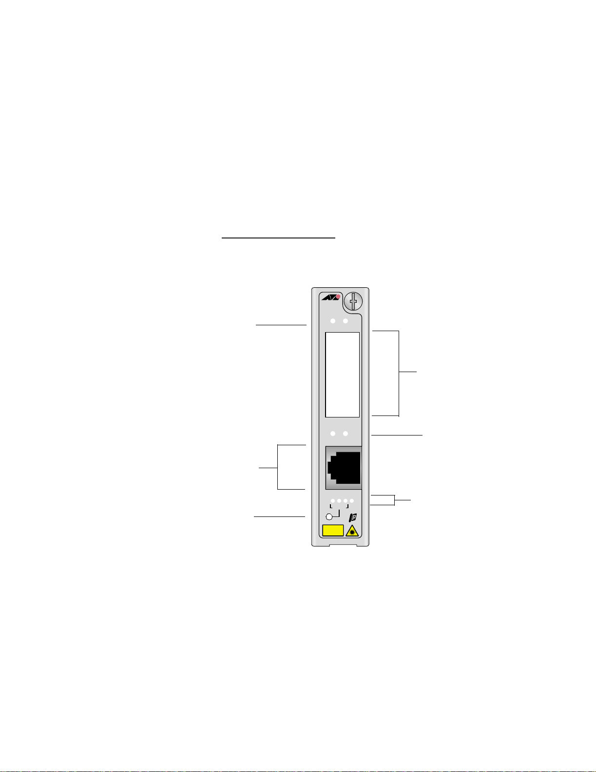
See Figure 1 for an illustration of the AT-PB1005G Gigabit Ethernet
Media Converter.
PB1005G
1000Mbps
Port Status LEDs
LKAT
RX
1000Base-X Port
(GBIC expansion slot)
TX
LK
AT
1000BASE-T1000BASE-X
1000Base-T Port
(RJ-45 connector)
LT SML ML
Mode Selection
Push Button
MODE
CLASS 1
LASER PRODUCT
DO NOT STARE
INTO BEAM
PR
Module Status LEDs
Figure 1 AT-PB1005G Gigabit Ethernet Media Converter
Port Status LEDs
PN 613-50381-00 Rev A 2 Allied Telesyn, Inc.
Page 3

Table 1 lists the connector types and cabling distances for the
AT-PB1005G module and the GBIC transceivers.
Table 1 Maximum Operating Distances
Port Connector Maximum Distance
1000Base-T
RJ-45 550 m (1,804 f t)
1000Base-SX
AT-G8SX
SC 220 m (721 ft)
500 m (1,640 ft)
1
2
1000Base-LX
AT-G8LX10
AT-G8LX25
AT-G8LX40
AT-G8LX70
1. Using 62.5/125 micron multimode fiber optic cable.
2. Using 50/125 micron multimode fiber optic cable.
3. Using 10/125 micron single-mode fiber optic cable.
SC 10 km (6.2 mi)
SC 25 km (15.5 mi)
SC 40 km (24.8 mi)
SC 70 km (43.4 mi)
3
3
3
3
For fiber optic cabling specifications for the GBIC transceivers, refer to
the AT-G8SX and AT-G8LX GBIC Transceivers Installation Guide.
Features
The AT-PB1005G media converter has the following features:
❑ LEDs for unit and port status
❑ 1000Base-T twisted pair port with a maximum operating distance
of 550 meters (1,804 feet)
❑ Expansion slot for an 1000Base fiber optic GBIC transceiver with a
maximum operating distance of 220 meters (721 feet) to 70
kilometers (43.4 miles), depending on the model and type of fiber
optic cable used
❑ Full-duplex operation on both ports
❑ Mode selection button to toggle between Link Test, Smart
MissingLink, and MissingLink
PN 613-50381-00 Rev A 3 Allied Telesyn, Inc.
Page 4

Status LEDs
Table 2 list the status LEDs.
Table 2 AT-PB1005G Status LEDs
LED Color Description
PR Green Power is applied to the media converter.
AT Green Data is being received or transmitted on the port.
LK Green A link has been established on the port.
Mode Status
LT Green Link test is enabled.
SML Green Smart MissingLink is enabled.
ML Green MissingLink is enabled.
Twisted Pair Port
The 1000Base-T port on the AT-PB1005G media converter has an RJ-45
connector and is designed to operate with Category 5 or better shielded
or unshielded twisted pair cable.
An RJ-45 twisted pair port on a 1000 Mbps Ethernet network device can
have one of two possible wiring configurations: MDI or MD I-X. The RJ- 45
port on a PC, router, or bridge is typically wired as MDI, while the twisted
pair port on a switch or hub is usually MDI-X.
To connect two network devices that have dissimilar wiring
configurations, such as MDI to MDI-X, you use a straight-through twisted
pair cable. To connect two network devices that have the same wiring
configuration, such as MDI to MDI, you use a crossover cable.
The AT-PB1005G media converter features automatic MDI/MDI-X. Each
port automatically determines the configuration of the port on the
device to which it is connected and then configures itself appropriately.
For example, if a port on a media converter is connected to a port on a
bridge, which is typically wired as MDI, the port on the media converter
automatically configures itself as MDI-X. This feature allows you to use
either straight-through or crossover cables when connecting devices to
the media converter. This eliminates the need for a cross-over cable.
PN 613-50381-00 Rev A 4 Allied Telesyn, Inc.
Page 5

Pinout
Assignments
Figure 2 shows the pin assignments of the RJ-45 connector.
Pin 1
Pin 8
Figure 2 RJ-45 Pin Assignments
Table 3 lists the RJ-45 connector pins and their signals for a 1000Base-T.
Table 3 RJ-45 Connector Pinouts
Pinout Pair Signal
1 0 TX and RX+
2 0 TX and RX3 1 TX and RX+
4 2 TX and RX+
5 2 TX and RX6 1 TX and RX7 3 TX and RX+
8 3 TX and RX-
PN 613-50381-00 Rev A 5 Allied Telesyn, Inc.
Page 6

Fiber Optic Port (GBIC Transceivers)
The 1000Base-SX port on the GBIC transceiver has an SC connector and
is designed to operate with multimode fiber optic cabling. This port has
a maximum operating distance of 220 meters (721 feet) using 62.5/125
micron or 500 meters (1,640 feet) using 50/125 micron multimode fiber
optic cable.
The 1000Base-LX port on the GBIC transceiver has an SC connector and
is designed to operate with single-mode fiber optic cabling. This port
has a maximum operating distance of 10 kilometers (6.2 miles) to 70
kilometers (43.4 miles), depending on your model, using 10/125 micron
single-mode fiber optic cable.
Duplex Mode
Duplex mode refers to the way an end-node sends and receives data on
the network. An end-node can operate in either half- or full-duplex
mode, depending on its capabilities. An end-node that is operating in
half-duplex mode can either send data or receive data, but it cannot do
both at the same time. An end-node that is operating in full-duplex
mode can send and receive data simultaneously. The best network
performance is achieved when an end-node can operate at full-duplex,
since the end-node is able to send and receive data simultaneously.
The AT-PB1005G media converter operates in full-duplex mode only.
The media converter can operate with end-nodes capable of either fullduplex mode or that can auto-negotiate the duplex mode. However, it is
important to remember that the two end-nodes connected to the ports
on the media converter must be able to operate in full-duplex mode.
PN 613-50381-00 Rev A 6 Allied Telesyn, Inc.
Page 7

Mode Selection Button
Link Test The link test is a fast and easy way for you to test the connections
between the media converter ports and the end-nodes that are
connected to the ports. If a network problem occurs, you can perform a
link test to determine which port is experiencing a problem, and be able
to focus your troubleshooting efforts on the cable and end-node where
the problem resides.
A link test is performed when the Mode Selection button is toggled until
the LT LED is green. For instructions on performing a link test, refer to
“Troubleshooting” in the PowerBlade PBC18 Installation Guide.
MissingLink The MissingLink feature enables the ports on the media converter to
pass the “Link” status of their connections to each other. When the
media converter detects a problem with one of the ports, such as the
loss of connection to a end-node, the media converter shuts down the
connection to the other port, thus notifying the end-node that the
connection has been lost.
Note
Performing a link test does not interfere with a media converter’s
ability to pass network traffic.
For example, if the network twisted pair cable on a AT-PB1005G were to
fail, the module would respond by dropping the link on the fiber optic
port. In this way, the AT-PB1005G notifies the end-node connected to
the fiber optic port that the connection on the twisted pair port has
been lost. If the failure had started with the fiber optic cabling, the unit
would drop the link to the twisted pair port.
The value to this type of network monitoring and fault notification is that
some hubs and switches can be configured to take a specific action in
the event of the loss of connection on a port. In some cases, the unit can
be configured to seek a redundant path to a disconnected end-node or
send out a trap to a network management station, alerting the network
administrator of the problem.
Note
MissingLink or Smart MissingLink is disabled when you perform a
link test. Consequently, to ensure that the MissingLink or Smart
MissingLink is enabled on the media converter, always set the Mode
Selection button so that the ML or SML LED is green during normal
network operations.
PN 613-50381-00 Rev A 7 Allied Telesyn, Inc.
Page 8

Smart
MissingLink
Like MissingLink, the Smart MissingLink feature terminates the link on
the failed port thereby notifying you when a connection has been lost.
Additionally, Smart MissingLink indicates on which port the connection
has failed. This is shown by a blinking LK LED on the good port.
For example, if the network twisted pair cable to the 1000Base-T port on
the media converter were to fail, the LK LED on the 1000Base-X fiber
optic port will blink, indicating a failed connection on the twisted pair
port. The fiber optic port is still able to receive a signal.
The switch notifies the end-node connected to the fiber optic port that
the connection on the twisted pair port has been lost. If the failure had
started with the fiber optic cabling, the LK LED on the twisted pair port
would blink.
The value to this type of network monitoring and fault notification is so
that you can quickly see which port has failed and troubleshoot your
network accordingly.
Cable Specifications
Twisted Pair Port Table 4 lists the cabling specifications for the 1000Base-T twisted pair
port.
Table 4 1000Base-T Twisted Pair Specifications
Connector Cable Maximum Distance
RJ-45 Shielded or unshielded twisted
550 m (1,804 ft)
pair Category 5 or better
Fiber Optic Port Refer to the AT-G8SX and AT-G8LX GBIC Transceivers Installation
Guide for the cabling and fiber optic port specifications. This guide is
available from the Allied Telesyn web site at www.alliedtelesyn.com
.
Allied Telesyn, Inc. ! 960 Stewart Drive, Suite B ! Sunnyvale, CA 94085 USA
Copyright 2002 Allied Telesyn, Inc. All rights reserved. No part of this publication may be reproduced without prior written
PN 613-50381-00 Rev A 8 Allied Telesyn, Inc.
Tel (408) 730-0950 ! Fax (408) 736-0100 ! Technical Support Tel 1-800-428-4835 ! Fax 1 (425) 481-3790
permission from Allied Telesyn, Inc.
 Loading...