

Page 1

How To |
Create A Secure Network With Allied Telesis
Managed Layer 3 Switches
Introduction
Allied Telesis switches include a range of sophisticated security features at layer 2 and layer 3.
This How To Note describes these features and includes brief examples of how to configure
them.
The implementations shown in this How To Note should be thought of as industry-standard
best practices.
Contents
Introduction .............................................................................................................................................. 1
Which products and software versions does this information apply to? ................................... 2
Securing the device ................................................................................................................................. 3
Protecting the network .......................................................................................................................... 3
Protecting against packet flooding ................................................................................................ 3
Protecting against rapid MAC movement ................................................................................... 6
Controlling multicast traffic ........................................................................................................... 7
Managing the device securely ................................................................................................................ 9
Using Secure Shell (SSH) ................................................................................................................ 9
Using SSL for secure web access ................................................................................................ 10
Using SNMPv3 ................................................................................................................................ 10
Whitelisting telnet hosts .............................................................................................................. 12
Identifying the user ................................................................................................................................ 14
IP spoofing and tracking ................................................................................................................ 14
Rejecting Gratuitous ARP (GARP) ............................................................................................ 15
DHCP snooping ............................................................................................................................. 15
1
Using 802.
Protecting the user ................................................................................................................................ 18
Using private VLANs ..................................................................................................................... 18
Using local proxy ARP and MAC-forced forwarding ............................................................. 19
Using IPsec to make VPNs ........................................................................................................... 24
Protecting against worms ............................................................................................................. 25
x port authentication ............................................................................................... 17
C613-16103-00 REV A
www.alliedtelesis.com
Page 2

Which products and software versions does this information apply to?
Appendix: Configuration scripts for MAC-forced forwarding example ................................... 27
Edge switch
1 .................................................................................................................. 27
Edge switch 2 .................................................................................................................................. 28
Edge switch 3 .................................................................................................................................. 29
Access Router ................................................................................................................................. 30
For information about the AlliedWare firewall, see the Firewall chapter of your Software
Reference, and the following How To Notes:
z How To Configure Some Basic Firewall And VPN Scenarios
z How To Apply Firewall Policies And Rules
How To Notes are available from www.alliedtelesis.com/resources/literature/howto.aspx.
Which products and software versions does this
information apply to?
This How To Note applies to the following Allied Telesis switch series:
z AT-8 60 0
z AT-8700XL
z AT-8 80 0
z Rapier i
z SwitchBlade
z AT-9 80 0
z AT-8948 and x900-48
z AT-9 90 0
z AT-9900s and x900-24
Some features are only available on some switches and/or some software versions.
Therefore, when this How To Note describes each feature, it lists the applicable switches and
versions.
Create A Secure Network With Allied Telesis Managed Layer 3 Switches 2
Page 3

Securing the device
Products
All switches listed on page 2
Software Versions
All
Securing the device
The first step towards making a secure network is to secure
the networking equipment itself.
There are two aspects to this. Firstly, physical security is
vital—lock your networking equipment away.
Secondly, straight after powering up any new piece of
networking equipment, change the default administrator user’s password. On an Allied
Telesis managed layer 3 switch, the default user is “manager”. To change the password, use
the following command:
set user=manager password=<new-password>
The default password is well-known. If you do not change it, anyone with physical or IP access
could reconfigure the switch.
Protecting the network
This section describes layer 2 based methods for controlling the negative impact of
misconfigured devices and misuse of the network. These solutions work at the Ethernet level
of a packet and cause no degradation in the switch's throughput.
You can protect your network against the following:
z traffic storms (“Protecting against packet flooding” on page 3)
z excessive MAC address learning (“Protecting against rapid MAC movement” on page 6)
z unwanted multicast traffic (“Controlling multicast traffic” on page 7)
Protecting against packet flooding
Service providers are often vulnerable to traffic storms, primarily when incorrectly
configured customer equipment is directly connected to the provider. Storms overwhelm a
subnet, and all of the switches in that subnet, with traffic. Such misconfiguration can quickly
lead to widespread outages and compromise guaranteed service levels.
Storms are a reality in any network. They can occur by accident, maliciously, or when a
network device fails. They occur naturally in a network where switches are connected more
than once to the same VLAN, so administrators must employ a method to prevent these
switch loops.
Spanning Tree Protocol based solutions are the most common method of preventing loops.
However, incorrect configuration or other network issues can cause STP to fail. For example,
if a single switch in the VLAN does not have STP enabled, the STP tree will not converge
properly. Spanning tree protocols can even fail if a broadcast storm drowns out STP
messages.
Create A Secure Network With Allied Telesis Managed Layer 3 Switches 3
Page 4
Protecting the network
Products
All switches listed on page 2
Software Versions
All
flood of ARPs
flood of ARPs
secure-switch-bandwidth.eps
Service providers need to prevent storms from disrupting services to customers. AlliedWare
offers the following options for mitigating storms:
z limiting broadcasts and multicasts on a port (“Bandwidth limiting” on page 4)
z detecting a storm and disabling that port or VLAN (“Using QoS policy-based storm
protection” on page 5)
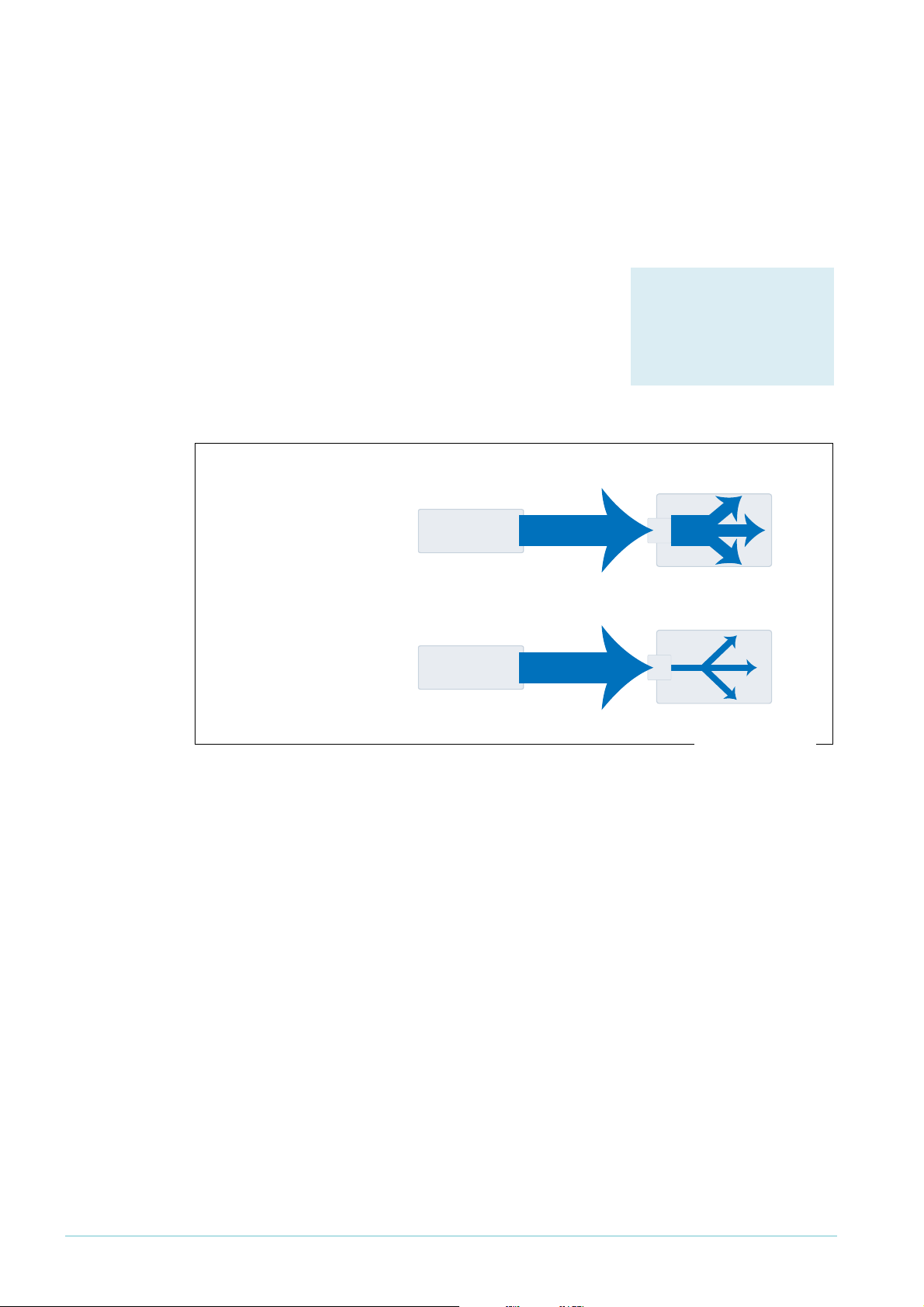
Bandwidth limiting
ARP packets are the most frequent trigger for broadcast
storms. One ARP packet is flooded around and around a
network, crowding out all other traffic.
You can use a simple Quality of Service (QoS) configuration
to match ARP packets and make sure that when a broadcast
storm occurs, the effect is minimised.
ISP switch
When ISP switch has
no bandwidth control:
misconfigured
customer switch
flood of ARPs
port
48
Configuration
Example
ISP switch
When ISP switch has
bandwidth limiting:
misconfigured
customer switch
flood of ARPs
port
48
To limit the bandwidth for ARPs:
1. Create a classifier to match ARP packets.
2. Create a QoS framework of policy, traffic class, and flow group. In the traffic class settings,
specify the maximum bandwidth for ARP traffic.
3. Apply the policy—and therefore the bandwidth limit—to one or more ports.
The following configuration limits ARP packets to 100kbps on port 48.
create classifier=1 protocol=0806 ethformat=ethii-untagged
create qos policy=1
create qos trafficclass=1 maxbandwidth=100
create qos flowgroup=1
add qos policy=1 trafficclass=1
add qos trafficclass=1 flowgroup=1
add qos flowgroup=1 classifier=1
set qos port=48 policy=1
Create A Secure Network With Allied Telesis Managed Layer 3 Switches 4
Page 5

Using QoS policy-based storm protection
Products
AT-8948
x900-48 Series
AT-9900 Series
AT-9924Ts
x900-24 Series
Software Versions
2.8.1 and later
Policy-based storm protection lets you specify one of a
range of actions for the switch to take when it detects a
broadcast storm. It is a part of the QoS functionality.
Policy-based storm protection is more powerful than simple
bandwidth limiting. It lets you restrict storm damage to
within the storming VLAN, and it gives you the flexibility to
define what traffic rate makes a broadcast storm.
Protecting the network
Configuration
To use storm protection:
1. Turn on the switch enhanced mode qoscounters, unless it is already enabled. After this,
you need to restart the switch.
2. Create a classifier to match the desired traffic. To match all broadcast packets specify a
destination MAC address of ff-ff-ff-ff-ff-ff.
3. Create a QoS traffic class and define the following storm protection settings in it:
z Window (stormwindow) specifies how often the switch measures traffic to decide
whether to activate storm protection (in seconds).
z Rate (stormrate) specifies the amount of traffic per second that must be exceeded
before the switch takes action.
z Action (stormaction) specifies what the switch does when it detects a storm:
Link Down (linkdown) makes the switch physically disable the port on which the
storm is occurring, so that the link goes down.
Port Disable (portdisable) makes the switch logically disable the port on which the
storm is occurring, leaving the link up.
VLAN Disable (vlandisable) makes the switch block traffic only on the VLAN on
which the storm is occurring.
z Timeout (stormtimeout) specifies the number of seconds that the port remains
disabled for.
4. Create the rest of the QoS framework: a flow group and policy. Add the classifier to the
flow group, the flow group to the traffic class, and the traffic class to the policy.
5. Apply the policy—and therefore the storm protection—to one or more ports.
The procedure above applies storm protection to classified traffic, and uses a classifier to
select all broadcast traffic. This is the most common approach. If you want to, you can instead
classify to select important non-broadcast traffic and apply storm protection to unmatched
traffic. Unimportant or unwanted unicast and multicast traffic then counts towards the storm
calculations.
To apply storm protection to unclassified traffic, configure storm protection on the default
traffic class in the QoS policy settings. Use the parameters dtcstormwindow,
Create A Secure Network With Allied Telesis Managed Layer 3 Switches 5
dtcstormrate, dtcstormaction, and dtcstormtimeout.
Page 6

Protecting the network
Products
AT-8948
x900-48 Series
AT-9900 Series
AT-9924Ts
x900-24 Series
Software Versions
2.8.1 and later
Example
The following example applies storm protection to classified broadcast traffic on port 1. If
there is a storm, it takes the link down for 60 seconds.
set switch enhancedmode=qoscounters
Reboot after turning on enhanced mode.
create classifier=1 macdaddr=ff-ff-ff-ff-ff-ff
create qos trafficclass=1 stormstatus=enable stormwindow=100
stormrate=100 stormaction=linkdown stormtimeout=60
The rest of the QoS configuration is as normal, so:
create qos flowgroup=1
add qos flowgroup=1 classifier=1
add qos trafficclass=1 flowgroup=1
create qos policy=1
add qos policy=1 trafficclass=1
set qos port=1 policy=1
You can view matching traffic at the port level with the command:
show qos port=1 count trafficclass
Protecting against rapid MAC movement
Configuration
on one or
more ports
Rapid MAC movement protection detects excessive MAC
address learning on a specific switch port. Once excessive
learning is detected, the switch stops learning MAC
addresses via the affected port.
Rapid MAC movement mostly occurs because of a
broadcast storm, when one packet is storming around a
layer 2 network. Rapid MAC movement protection is
simpler to configure than QoS policy-based storm
protection but is not guaranteed to stop all the varieties of
broadcast storm.
Rapid MAC movement protection is on by default. The default action is to disable learning for
1
second. This gives the CPU of the switch some idle time, which may let a fast STP-type
protocol converge. You can change the amount of idle time to suit your network, or select a
different action.
To customise the protection:
1. Set the parameters in the following command:
set switch port=<ports> thrashaction={learndisable|linkdown|none|
portdisable|vlandisable} thrashtimeout={none|1..86400}
vlanstatustrap={on|off}
The parameter thrashaction specifies the switch’s response to rapid MAC movement:
Create A Secure Network With Allied Telesis Managed Layer 3 Switches 6
z learndisable makes the switch temporarily disable learning on the port.
z linkdown makes the switch physically disable the port, so that the link goes down.
z portdisable makes the switch logically disable the port, leaving the link up.
z vlandisable makes the switch block traffic on only the VLAN on which the rapid
learning occurred.
Page 7

Protecting the network
Products
All switches listed on page 2
Software Versions
All
2. Set the sensitivity in detecting rapid MAC movement, by using the following command to
tell the switch how many times a MAC address can move ports in one second:
set switch thrashlimit=5..255
Configuration
on trunk
groups
Rapid MAC movement protection also works with trunk groups. If one switch in a trunk fails,
the switches probably cannot negotiate STP or any other trunks that they belong to. This
immediately causes a broadcast storm. Rapid MAC movement protection on the other
switch in the trunk group detects such a storm because flooding of the same packet occurs
on all trunk ports connected to the failed switch.
For a static trunk, to make use of rapid MAC movement protection, create the trunk and
specify the optional thrashaction and thrashtimeout parameters:
create switch trunk=<name> port=<ports>
thrashaction={learndisable|linkdown|none|portdisable|
vlandisable} thrashtimeout={none|1..86400}
For a dynamic trunk using LACP, enable LACP, add ports, and set the optional thrashaction
and thrashtimeout parameters:
enable lacp
add lacp port=<ports>
set lacp thrashaction={learndisable|linkdown|none|portdisable|
vlandisable} thrashtimeout={none|1..86400}
Controlling multicast traffic
In a busy network, or one that has subscription-only access to multicast services, tight
per-port control of multicast traffic is required. IGMP makes multicasting fairly efficient, but
the extra control offered by AlliedWare helps increase efficiency.
When multicasting, it is essential to avoid filling the network with unnecessary multicast data
and to make sure that the clients who join a group are entitled to receive it. It is also
important to minimise delays in joining a group and to efficiently handle those who leave a
group.
The following sections outline some of the IGMP controls that are particularly relevant for
security. For detailed information on how to control IGMP in the network, see How To
Configure IGMP for Multicasting on Routers and Managed Layer 3 Switches. This How To Note is
available from www.alliedtelesis.com/resources/literature/howto.aspx.
IGMP snooping
IGMP snooping is enabled by default on Allied Telesis
managed layer 3 switches. IGMP snooping monitors the
streams and clients involved in each multicast group,
independent from IP itself. A snooping switch ensures that
only ports that are interested in a group are sent it. This
basic level of management works in tandem with the
subnetwork's IGMP querier and makes sure that the querier
gets notified of any client who wants to join the group.
Create A Secure Network With Allied Telesis Managed Layer 3 Switches 7
Page 8

IGMP filtering
Products
All switches listed on page 2
that support 2.7.5 or later
Software Versions
2.7.5 or later
Products
All switches listed on page 2
that support 2.7.5 or later
Software Versions
2.7.5 or later
Example
IGMP filtering lets you dictate exactly which multicast
groups a specific port can receive, by creating a filter list and
applying it to the port. Different ports may have different
filter lists applied to them.
If desired, you can select the type of message to filter. By
default, filters apply to IGMP reports. You can create extra
entries to also filter queries (type=query) and leave
messages (type=leave).
Protecting the network
Configuration
Example
For each port:
1. Work out which groups you want users on the port to be able to join.
2. Create an IGMP filter.
3. Create entries to allow the appropriate groups (action=include).
Note: The order of entries in a filter is important. When IGMP tries to match a message
to a filter, it performs a linear search of the filter to find a matching entry. It tries
each entry in turn, and stops processing the filter after the first match it finds.
4. Create an entry to block all groups (action=exclude). Give this entry a higher entry
number than entries for the included groups.
5. Apply the filter to the port.
To stop the user attached to port 1 from joining any group except 224.12.13.14:
create igmp filter=1
add igmp filter=1 entry=1 group=224.12.13.14 action=include
add igmp filter=1 entry=2 group=224.0.0.0-239.255.255.255
action=exclude
set switch port=1 igmpfilter=1
IGMP throttling
Throttling limits the number of multicast groups that an
individual port can join.
To limit port 2 to a total of 6 groups:
set switch port=2 igmpmaxgroup=6
igmpaction=replace
Create A Secure Network With Allied Telesis Managed Layer 3 Switches 8
Page 9

Managing the device securely
Products
All switches listed on page 2
Software Versions
All
Configuration
Managing the device securely
In Ethernet and broadcast networks the privacy of traffic is not guaranteed. Hubs and
networks outside the administrator's control may leak sensitive data to unwanted recipients.
A hacker may even be able to force a switch to flood unicast traffic.
Because you cannot guarantee traffic privacy, you cannot be certain that management
sessions are private. Therefore, you should always use encrypted sessions when remotely
administering network equipment, even in networks that you know well. The simplest way to
achieve this is with Secure Shell (SSH).
This section describes secure management:
z “Using Secure Shell (SSH)” on page 9
z “Using SSL for secure web access” on page 10
z “Using SNMPv3” on page 10
Then the section ends by describing how to limit telnet access if you need to use telnet
instead of one of the recommended secure options (“Whitelisting telnet hosts” on page 12).
Example
When you are using a secure management scheme, we recommend that you block all telnet
access to the switch, by disabling the telnet server:
disable telnet server
Using Secure Shell (SSH)
The Secure Shell (SSH) protocol is most simply described as
an encrypted form of Telnet.
1. Add a security officer to your switch’s list of users.
2. Create encryption keys for SSH to use.
3. Enable the SSH server.
4. Add the security officer to the list of SSH users and specify a password for it. Only users
in this list can use SSH to access the switch.
5. Enable system security.
Enabling system security makes telnet unavailable as an administrative interface—once you
have configured SSH, you have to use it.
To configure SSH access for the security officer called “secoff”:
add user=secoff password=securepass privilege=security telnet=yes
login=yes
create enco key=0 type=rsa length=1024 description="Host Key"
form=ssh
create enco key=1 type=rsa length=768 description="Server Key"
form=ssh
enable ssh server serverkey=1 hostkey=0 expirytime=1
logintimeout=60
add ssh user=secoff password=sameordifferentpassword
enable system security
Create A Secure Network With Allied Telesis Managed Layer 3 Switches 9
Page 10
Managing the device securely
Products
All switches listed on page 2,
except AT-8948 and x900-48
Series which have no
graphical user interface
Software Versions
All
Configuration
Products
All switches listed on page 2
Software Versions
2.6.4 and later
Using SSL for secure web access
If you prefer to configure the switch using the convenient
web-based GUI, then this is unencrypted by default. SSL lets
you use the GUI securely, by using HTTPS instead of HTTP.
1. Add a security officer to your switch’s list of users.
2. Create an encryption key for SSL to use.
3. Create a self-signed PKI certificate, or load a certificate
generated by a Certificate Authority (CA) if you have
one.
4. Add the certificate to the certificate database.
5. Turn security on for the HTTP server.
6. Enable system security.
Once you have configured SSL, HTTPS connections to the device are available only on
port 443.
Example
To allow the security officer called “secoff” to browse securely to the GUI, using a self-signed
certificate:
add user=secoff password=secoff privilege=securityofficer
login=yes
create enco key=0 type=rsa length=1024
set system distinguishedname="cn=switch1,o=my_company,c=us"
create pki certificate=cer_name keypair=0 serialnumber=12345
subject="cn=172.30.1.105,o=my_company,c=us"
add pki certificate=cer_name location=cer_name.cer trust=yes
set http server security=on sslkey=0 port=443
enable system security
Using SNMPv3
Traditionally, SNMP has been a popular but insecure way to
monitor networks.
Allied Telesis devices are SNMPv3 compliant. By using
SNMPv3, you can authenticate SNMP users and restrict
their network access to parts of the network. SNMPv3 is
very flexible, as the examples in this section show.
Configuration
Create A Secure Network With Allied Telesis Managed Layer 3 Switches 10
1. Enable SNMP.
2. Set up one or more SNMP views. Views list the objects in the MIB that users can see.
3. Set up one or more groups and add the groups to the views. Each group is a collection of
users who have the same access rights.
4. Set up one or more users and add them to the groups. Authentication parameters are set
here.
5. Set up a traphost profile, for trap messages to be remotely sent to. This is not compulsory
but we recommend it.
Page 11

Managing the device securely
Examples
To allow the user “steve” full read, write and notify SNMP access to the switch:
enable snmp
add snmp view=full oid=1.3.6.1 type=include
add snmp group=super-users securitylevel=authPriv readview=full
writeview=full notifyview=full
add snmp user=steve group=super-users authprotocol=md5
authpassword=cottonsox privprotocol=des privpassword=woollytop
To also give the user “jane” read and notify access to everything on the switch, add the
following commands:
add snmp group=users securitylevel=authNoPriv readview=full
notifyview=full
add snmp user=jane group=users authprotocol=md5
authpassword=redjeans
To also give the user “paul” unauthenticated read access to everything on the switch except
BGP, add the following commands:
add snmp view=restricted oid=1.3.6.1 type=include
# exclude bgp by specifying either mib=bgp or oid=1.3.6.1.2.1.15:
add snmp view=restricted mib=bgp type=exclude
add snmp group=restricted-users securitylevel=noAuthNoPriv
readview=restricted
add snmp user=paul group=restricted-users
To also send traps securely to the PC with IP address 192.168.11.23 for user “steve” to see,
add the following commands:
add snmp targetparams=netmonpc securitylevel=authPriv user=steve
add snmp targetaddress=nms ip=192.168.11.23 udp=162
params=netmonpc
For more information about the above examples, see How To Configure SNMPv3 On Allied
Telesis Routers and Managed Layer 3 Switches, available from www.alliedtelesis.com/resources/
literature/howto.aspx. This How To Note also explains SNMPv3 concepts in detail, including
users, groups and views.
Create A Secure Network With Allied Telesis Managed Layer 3 Switches 11
Page 12

Managing the device securely
Products
AT-8600 Series
AT-8700XL Series
Rapier i Series
Rapier Series
AT-8800 Series
Software Versions
All
Configuration
Whitelisting telnet hosts
For any remote management of a network device, Allied Telesis recommends you use SSH,
Secure HTTP (SSL), or SNMPv3. Therefore, we recommend you block all telnet access to
the switch by disabling the telnet server. However, if you persist with telnet, you should make
a whitelist of the hosts that are permitted to telnet to the switch. This does not make telnet
secure, but it does reduce the associated risks.
Building a whitelist through layer 3 filters
On Rapier, Rapier i, AT-8800, AT-8700XL and AT-8600
Series switches, use layer 3 filters to build a whitelist.
1. Create a filter match definition that specifies destination
IP address, protocol and destination TCP port as the
criteria that the filter will match. The switch
automatically assigns this filter an ID of
layer 3 filters already exist).
2. Create a filter entry that specifies the switch’s IP address
as the destination address, TCP as the protocol and 23
as the port. Give it an action of deny.
1
(unless other
Example
3. Create another filter match definition with source and destination IP addresses, both with
32-bit masks.
4. Create filter entries for the second filter. In each entry, specify a permitted host as the
source and the switch’s IP address as the destination. Give the entries an action of nodrop.
The first filter blocks (action=deny) any incoming telnet packets with the switch’s
destination IP address. The second filter reverses the first filter by undoing the previous
denial of IP access to the switch—but only for the permitted source IP addresses.
To permit only the host with IP address 172.30.1.144 to telnet to the switch 172.28.40.70:
add switch l3filter match=dipaddress,protocol,tcpdport dclass=32
add switch l3f=1 entry protocol=tcp dipaddress=172.28.40.70
tcpdport=23 action=deny
add switch l3filter match=dipaddress,sipaddress sclass=32
dclass=32
add switch l3filter=2 entry sipaddress=172.30.1.144
dipaddress=172.28.40.70 action=nodrop
Create A Secure Network With Allied Telesis Managed Layer 3 Switches 12
Page 13

Managing the device securely
Products
AT-8948
x900-48 Series
AT-9900 Series
AT-9924Ts
x900-24 Series
Software Versions
2.7.3 and later
Configuration
Building a whitelist through QoS
On AT-8948, AT-9900, AT-9900s, and x900 Series switches,
use classifiers to build a whitelist and QoS to apply it.
1. Create classifiers to match telnet traffic from permitted
IP addresses to the switch’s IP address.
2. Create a classifier to match all telnet traffic to the
switch’s IP address.
3. Create a flow group and add the classifiers for permitted
traffic to it.
4. Create a second flow group with a higher ID number and
add the classifier that matches all telnet traffic to it.
5. Create the rest of the QoS framework—traffic class and policy.
6. Apply the policy to all ports to stop telnet from all directions.
QoS is an incredibly versatile hardware-level packet filtering mechanism. For more
information about setting up QoS on these switches, see How To Configure QoS On AT-8948,
AT-9900, AT-9900s And x900 Series Switches. This How To Note is available from
www.alliedtelesis.com/resources/literature/howto.aspx.
Example
To permit only the host with IP address 172.30.1.144 to telnet to the switch 172.28.40.70:
create classifier=1 ipsa=172.30.1.144/32 ipda=172.28.40.70/32
tcpd=23
create classifier=2 ipda=172.28.40.70/32 tcpd=23
create qos flowgroup=1 action=forward
create qos flowgroup=2 action=discard
create qos trafficclass=1
create qos policy=1
add qos flowgroup=1 classifier=1
add qos flowgroup=2 classifier=2
add qos trafficclass=1 flowgroup=1
add qos trafficclass=1 flowgroup=2
add qos policy=1 trafficclass=1
set qos port=all policy=1
Create A Secure Network With Allied Telesis Managed Layer 3 Switches 13
Page 14

Identifying the user
Identifying the user
This section describes methods for authorising and tracking users and preventing them from
changing their identity on the network.
IP spoofing and tracking
Unknown users who attempt to change IP address—to circumvent billing or to hide their
identity—can be a problem for administrators.
Changing IP address for malicious reasons is most commonly called IP spoofing, and is also
known as ARP spoofing, ARP poisoning, and ARP poison routing (APR). The net result is the
same for all of these: the victim ends up with false information in its ARP table.
The trouble with ARP
IP Spoofing takes advantage of the inherently insecure design of ARP. In an Ethernet network,
a client may use a Gratuitous ARP (GARP), or merely send an ARP request or reply with
false information, to announce a phoney identity to the local subnet.
A phoney announcement may be made in a number of ways for a number of reasons. The
following table briefly explains these factors.
If the ARP or GARP packet contains... Then...
MAC that does not exist on network and
IP address that does not exist on network
MAC that is owned by attacker and
IP address that does not exist on network
MAC that is owned by attacker and
IP address that is owned by another host
MAC that is owned by attacker and
IP address that is owned by the subnet router
MAC does not exist on network and
IP address that exists on network
the attacker may be trying to fill up the IP ARP table
so that the subnet’s router cannot learn more
addresses. As a result, return (routed) traffic may
not be forwarded.
the attacker is using an IP address that the
administrator has not assigned and so may be trying
to avoid traceability.
the attacker is trying to intercept traffic destined for
this host.
the attacker is trying to intercept all traffic leaving
the subnet.
the attacker is trying to cause traffic to this IP
address to flood to all hosts in the subnet. However,
hosts disregard the flooded traffic because it is not
addressed with any host’s MAC address. This means
that the attacker receives the traffic and its intended
recipient ignores it.
The techniques for protecting the network are the same for all these phoney
announcements: reject gratuitous ARPs, and control access to ports with DHCP snooping
and ARP security. The following sections describe these solutions in detail.
Create A Secure Network With Allied Telesis Managed Layer 3 Switches 14
Page 15

Identifying the user
Products
All switches listed on page 2
Software Versions
2.5.1 and later
Products
AT-8600 Series
AT-8700XL Series
Rapier i Series
Rapier Series
AT-8800 Series
AT-8948
x900-48 Series
AT-9900 Series
Software Versions
2.7.6 and later
Rejecting Gratuitous ARP (GARP)
Hosts can use GARP to announce their presence on a
subnet. It is a helpful mechanism, particularly when there is
a chance of duplicate addresses. However, attackers can use
GARP to penetrate the network by adding themselves to
the switch’s ARP table.
You can configure Allied Telesis switches and routers to ignore GARP packets. Ignoring
GARPs does not completely prevent IP spoofing, but it does shut down one easy avenue for
an attacker.
Example
To ignore GARPs on VLAN 1:
set ip interface=vlan1 gratuitousarp=off
Note: We do not recommend disabling GARP reception if a server with teamed network
cards is attached to the switch. In a teamed-NIC redundancy set-up, another card
takes over if a card fails. In many implementations, the NIC that takes over sends a
GARP to inform the switch of the port and MAC address change.
DHCP snooping
The AlliedWare DHCP snooping feature is a series of layer 2
techniques. It works with information from a DHCP server
to:
z track the physical location of hosts
z ensure that hosts only use the IP addresses assigned to
them
z ensure that only authorised DHCP servers are accessible.
In short, DHCP snooping ensures IP integrity on an L2switched domain.
Create A Secure Network With Allied Telesis Managed Layer 3 Switches 15
With DHCP snooping, only a whitelist of IP addresses may
access the network. You configure this whitelist at the switch
port level, and the DHCP server manages the access control. Only specific IP addresses with
specific MAC addresses on specific ports may access the IP network.
DHCP snooping also stops attackers from adding their own DHCP servers to the network.
An attacker could set up a server to wreak havoc in the network or even control it.
There are a number of options for DHCP snooping. You can:
z let the switch snoop DHCP packets and decide who is authorised to access the IP
network. See “Setting up DHCP snooping” on page 16.
z statically bind IP address and MAC combinations to switch ports. See “Using static binding
for rigid control” on page 16.
z use option 82 to track users. See “Using DHCP snooping to track clients” on page 17.
z use ARP security to reject ARP messages unless they come from an IP address in the
DHCP snooping database. See “Using ARP security” on page 17.
Page 16

Identifying the user
For more information about setting up DHCP snooping, see How To Use DHCP Snooping,
Option 82 and Filtering on Rapier, AT-8800 and AT-8600 Series Switches or How To Use DHCP
Snooping, Option 82 and Filtering on x900 Series Switches. These How To Notes are available
from www.alliedtelesis.com/resources/literature/howto.aspx.
Setting up DHCP snooping
This section describes a minimal configuration for DHCP snooping. With this configuration,
the switch snoops DHCP packets to build a database of allowed IP addresses, only sends
DHCP messages to the port with the official DHCP server, and limits the number of clients
attached to each port.
Configuration
Example
1. Enable DHCP snooping.
2. Identify the port that your DHCP server is attached to, and configure this as a trusted port
for DHCP snooping. The switch only sends DHCP discover and request packets to trusted
ports. If a malicious user attaches a DHCP server to an untrusted port, that server will
never receive DHCP requests. This prevents DHCP server spoofing.
3. Set the number of leases permitted on each port.
4. For AT-8948, x900-48, and AT-9900 switches, add classifiers and a quality of service (QoS)
configuration to permit and filter addresses.
To limit each port on a 24-port switch to 1 lease, when the DHCP server is on port 24:
enable dhcpsnooping
set dhcpsnooping port=24 trusted=yes
set dhcpsnooping port=1-23 maxlease=1
On AT-8948, x900-48 and AT-9900 switches, also add the following commands:
create classifier=50 macsaddr=dhcpsnooping prot=ip
ipsaddr=dhcpsnooping
create classifier=51 protocol=ip
create qos policy=1
create qos trafficclass=1
create qos flow=50 action=forward
create qos flow=51 action=discard
add qos policy=1 trafficclass=1
set qos port=1-23 policy=1
add qos trafficclass=1 flow=50
add qos trafficclass=1 flow=51
add qos flow=50 classifier=50
add qos flow=51 classifier=51
Using static binding for rigid control
If there is no DHCP server, or if there is a host with a static IP address, then you can bind the
IP address to the port to which it is attached.
Example
Create A Secure Network With Allied Telesis Managed Layer 3 Switches 16
To specify that the host with MAC address 00-00-00-00-00-12 can legitimately use the IP
1
address
72.16.0.12 on port 12, use the following command in addition to the configuration
given in “Setting up DHCP snooping”, above.
add dhcpsnooping binding=00-00-00-00-00-12 ip=172.16.0.12
interface=vlan1 port=12
Page 17

Identifying the user
Products
All switches listed on page 2
Software Versions
2.6.1 and later
Using DHCP snooping to track clients
If your DHCP server supports it, you can use “option 82” to record more information about
DHCP clients. This enhances your ability to track users. The switch can pass option 82
information to the DHCP server so that the server can record the switch MAC, switch port,
VLAN number and subscriber-ID that the client is a member of.
Example
Example
To pass option 82 information to the server, including the information that port 1 is room
101
, use the following commands in addition to the configuration given in “Setting up DHCP
snooping” on page 16.
enable dhcpsnooping option82
set dhcpsnooping port=1 subscriberid="Room 101"
Using ARP security
When you enable ARP security, the switch drops ARP packets received on non-trusted
(client) ports unless the packets originate from an IP address that is registered in the DHCP
snooping database.
ARP security stops clients that are directly attached to the switch from using IP spoofing or
ARP poisoning. It also protects directly-attached clients from IP spoofing and ARP poisoning.
To turn on ARP security, use the following command in addition to the configuration given in
“Setting up DHCP snooping”, above.
enable dhcpsnooping arpsecurity
Using 802.1x port authentication
With 802.1x port authentication, hosts must authenticate
themselves when they attempt to access a network through
an Ethernet port.
Examples
Unlike DHCP snooping, 802.
1
x only authenticates users
when they access the port. It cannot track them afterwards.
A network controller, such as a RADIUS server, controls the authentication. The Allied
Telesis switch facilitates the host to server communication and takes note of success or
failure. Essentially, the host is completely denied access to the Ethernet until the switch sees
the host successfully authenticate with the server. After that, the switch allows packets to
1
and from the host to pass through the 802.
1
x can also dynamically assign the host to a VLAN.
802.
x controlled port.
For examples of 802.1x authentication, see the following How To Notes:
z How to Configure A Secure School Network Based On 802.
z How To Use 802.
z How To Use 802.
1
x VLAN Assignment
1
x EAP-TLS or PEAP-MS-CHAP v2 with Microsoft Windows Server 2003 to
1
x
Make a Secure Network
z How To Use 802.
1
x Security with AT-WA7400 APs, AT-8624PoE Switches, and Linux’s
freeRADIUS and Xsupplicant
Most of the above Notes describe how to configure the authentication server and the host,
as well as the switch.
Create A Secure Network With Allied Telesis Managed Layer 3 Switches 17
Page 18

Protecting the user
Products
AT-8600 Series
AT-8700XL Series
Rapier i Series
Rapier Series
AT-8800 Series
AT-8948
x900-48 Series
AT-9900 Series
AT-9924Ts
x900-24 Series
Software Versions
All
switch
uplink port
hacker
legitimate
customer
Protecting the user
This section describes the following methods of protecting users from other users on the
network:
z “Using private VLANs” on page 18. This feature isolates switch ports in a VLAN from
other switch ports in the same VLAN.
z “Using local proxy ARP and MAC-forced forwarding” on page 19. These features force all
traffic in a network to go via an access router.
z “Using IPsec to make VPNs” on page 24. This feature creates secure tunnels through an
insecure network.
z “Protecting against worms” on page 25. These methods reduce the damage worms do to
users of the network.
Using private VLANs
Private VLANs are an excellent way of preventing hosts on
a subnet from attacking each other. Essentially, each switch
port is isolated from other ports in the VLAN, but can
access another network through an uplink port or uplink
trunk group. All traffic between private ports is blocked, not
just Layer 2 traffic.
Configuration
Private VLANs are reasonably flexible. A
private port can be a member of multiple
private VLANs. However, a port cannot be a
private port in some VLANs and a non-private
port in others.
On AT-8600, AT-8700XL, Rapier i and AT-8800
1
Series switches running 2.9.
or later, each
private VLAN can have multiple uplink ports.
This allows you to use private VLANs on
switches that are connected in a ring topology. Also, you can group private
ports together on these switches, which allows the ports in a group to
communicate with each other but not with other ports in the VLAN.
Note that ports are only isolated from ports on the same physical switch, not
from ports on other switches reached through an uplink port.
1. Create the VLAN, specifying that it is private.
2. Add the uplink port, or the ports in the uplink trunk group, to the VLAN. For a trunk
group, the ports must already be trunked together, and you must specify all the ports in
the trunk group. Note that on Rapier 48i and AT-8748XL switches, the uplink and private
ports must be in the same switch instance. See the Switching chapter of the Software
Reference for more information about switch instances.
3. Add the private ports to the VLAN.
Create A Secure Network With Allied Telesis Managed Layer 3 Switches 18
Page 19

Protecting the user
Example
To create a private VLAN with ports 2-6 in it, with an uplink trunk group of ports 24 and 25:
create vlan=example vid=2 private
add vlan=2 port=24-25 frame=tagged uplink
add vlan=2 port=2-6
To remove ports from the VLAN:
# remove port 4:
delete vlan=2 port=4
# remove all private ports and the uplink ports:
delete vlan=2 port=all
Using local proxy ARP and MAC-forced forwarding
Both these features ensure the integrity of ARP in your network and let you take granular
control of IP traffic flows. They do this by forcing traffic that would have been dropped by
private VLANs to go via an access router. Both features stop hosts from learning the MAC
addresses of other hosts in their subnet—they learn the MAC address of the access router
instead.
You can use these features, for example, to allow customers to use VoIP to telephone each
other while blocking any video, data, or management traffic between customers.
MAC-forced forwarding (page 23) requires more configuration than local proxy ARP
(page 20) but is more powerful. MAC-forced forwarding:
z ensures that all ARP replies are generated by the directly-connected switch (not the access
router). This removes the ARP process from the access router, minimises the distance
ARPs travel through the network, and protects against ARP Denial of Service attacks.
z dynamically determines the appropriate access router for a host by snooping DHCP
packets.
z bypassing the access router for traffic between application servers and their clients.
With software versions 291-05 and later, you can use MAC-forced forwarding without
configuring private VLANs. However, we recommend you use it with private VLANs for
maximum security.
Create A Secure Network With Allied Telesis Managed Layer 3 Switches 19
Page 20

Protecting the user
macff.eps
Products
All switches listed on page 2
Software Versions
2.9.1 or later
The following figure shows a network that can use either local proxy ARP or MAC-forced
forwarding—the examples in both the following sections refer to this network.
Internet
Management
PC
SIP and Multicast
server
Access
Router
24
5
20
12
LACP
Residential
Gateway 1
Residential
Gateway 2
Residential
Gateway 3
Edge
Switch 3
50
49
Edge
Switch 1
Edge
Switch 2
12
15
49
50
49
50
14
15
Local proxy ARP
In a network configuration like the previous figure, each
edge switch uses private VLANs to stop clients from talking
directly to each other. Private VLANs stop the edge switch
from flooding broadcast traffic, including clients’ ARP
requests. Instead, the switch sends ARP requests out its
uplink port to the access router.
Client 1
Client 2
Client 3
If local proxy ARP is configured on the access router, then the access router responds to
ARP requests with its own MAC address, instead of the destination device’s MAC address.
This combination of private VLANs and local proxy ARP forces the clients to send all their
traffic to the access router. When the access router sees traffic from a client, it checks a list
of filters to determine whether to forward the traffic or drop it.
On each client residential gateway, you need to enable tagged VLANs on the connection to
the edge switch for the VLANs that the client should be able to access.
Create A Secure Network With Allied Telesis Managed Layer 3 Switches 20
Page 21

Protecting the user
Configuration
of edge
switches
Configuration
of access
router
Example
1. Create the VLANs, specifying that they are private. Make a different VLAN for each type
of traffic that you want to control differently.
2. Add the uplink and private ports to the VLANs as tagged ports.
3. Configure any other requirements, such as a management IP address.
1. Create the VLANs.
2. Add the ports to the VLANs as tagged ports.
3. Enable IP.
4. Give each VLAN an IP address and turn on local proxy ARP.
5. Create classifiers and filters to decide which traffic to block.
6. Configure any other required networking features.
To allow VoIP (voice) but no other traffic between clients in the above network, use the
1
following configuration for edge switch
ena stp=default
set stp=default mode=rapid
delete lacp port=3-50
enable lacp
(an AT-8648 switch in this example):
create vlan="voice" vid=101 private
add vlan=101 port=1-2,49-50 uplink frame=tagged
add vlan=101 port=3-48 frame=tagged
create vlan="video" vid=102 private
add vlan=102 port=1-2,49-50 uplink frame=tagged
add vlan=102 port=3-48 frame=tagged
create vlan="data" vid=103 private
add vlan=103 port=1-2,49-50 uplink frame=tagged
add vlan=103 port=3-48 frame=tagged
create vlan="management" vid=104 private
add vlan=104 port=1-2,49-50 uplink frame=tagged
add vlan=104 port=3-48 frame=tagged
# Give the management VLAN an appropriate IP address
enable ip
add ip int=vlan104 ip=<address-in-192.168.4.0-subnet>
Create A Secure Network With Allied Telesis Managed Layer 3 Switches 21
Page 22

Protecting the user
Use the following configuration for edge switches 2 and 3 (AT-8648 switches in this
example):
ena stp=default
set stp=default mode=rapid
create vlan="voice" vid=101 private
add vlan=101 port=49-50 uplink frame=tagged
add vlan=101 port=1-48 frame=tagged
create vlan="video" vid=102 private
add vlan=102 port=49-50 uplink frame=tagged
add vlan=102 port=1-48 frame=tagged
create vlan="data" vid=103 private
add vlan=103 port=49-50 uplink frame=tagged
add vlan=103 port=1-48 frame=tagged
create vlan="management" vid=104 private
add vlan=104 port=49-50 uplink frame=tagged
add vlan=104 port=1-48 frame=tagged
# Give the management VLAN an appropriate IP address
enable ip
add ip int=vlan104 ip=<address-in-192.168.4.0-subnet>
Use the following configuration for the access router (a Rapier 24i switch in this example):
delete lacp port=3-24
enable lacp
create vlan="voice" vid=101
create vlan="video" vid=102
create vlan="data" vid=103
create vlan="management" vid=104
add vlan=101 port=1-2 frame=tagged
add vlan=102 port=1-2 frame=tagged
add vlan=103 port=1-2 frame=tagged
add vlan=104 port=1-2 frame=tagged
enable ip
add ip int=vlan101 ip=192.168.1.254 proxy=local
add ip int=vlan102 ip=192.168.2.254 proxy=local
add ip int=vlan103 ip=192.168.3.254 proxy=local
add ip int=vlan104 ip=192.168.4.254 proxy=local
Create A Secure Network With Allied Telesis Managed Layer 3 Switches 22
Page 23

Protecting the user
Products
AT-8600 Series
AT-8700XL Series
Rapier Series
AT-8800 Series
AT-8948
x900-48 Series
AT-9900 Series
Software Versions
2.9.1 or later
# Create a classifier to match all traffic in VLANs 101-104
create class=10 ipsa=192.168.0.0/16 ipda=192.168.0.0/16
# Create a classifier to match voice traffic
create class=100 ipsa=192.168.1.0/24 ipda=192.168.1.0/24
# Create a classifier to match management traffic
# The management PC is 192.168.4.250
create class=401 ipsa=192.168.4.0/24 ipda=192.168.4.250/32
create class=402 ipsa=192.168.4.250/32 ipda=192.168.4.0/24
# Create a filter to drop traffic within and between VLANs 101-104
add switch hwfilter classifier=10 action=discard
# Create filters to allow the exceptions (voice and management)
add switch hwfilter classifier=100 action=nodrop
add switch hwfilter classifier=401 action=nodrop
add switch hwfilter classifier=402 action=nodrop
MAC-Forced Forwarding (MACFF)
MAC-forced forwarding works in conjunction with DHCP
snooping to give you full control over IP flows in a layer 2
network.
Like local proxy ARP, MACFF replies to a client’s ARP
request with the MAC address of an access router, instead
of the real MAC address of the IP requested.
With MACFF, the edge switch generates the ARP reply. The
edge switch works out which MAC address to reply with
from information provided by DHCP snooping. DHCP
snooping keeps a record of the client’s IP, MAC and port
assignment. It also records the router information that the
client has been given by DHCP. DHCP snooping passes this
information to MACFF, so that MACFF knows which router’s MAC address to provide when
it sees an ARP from that client.
For more information about how MACFF works, see How To Use MAC-Forced Forwarding with
DHCP Snooping to Create Enhanced Private VLANs. This How To Note is available from
www.alliedtelesis.com/resources/literature/howto.aspx.
Create A Secure Network With Allied Telesis Managed Layer 3 Switches 23
Page 24

Protecting the user
Products
Rapier i Series
Rapier Series
AT-8800 Series
Software Versions
All
Configuration
of edge
switches
Configuration
of access
router
1. Create a VLAN for each type of service (for example, voice, video, and data). With
software versions 291-04 and earlier, the VLANs must be private VLANs. With software
versions 291-05 and later, you can use non-private VLANs. However, we recommend you
use private VLANs for maximum security.
2. Add the uplink and private ports to the VLANs as tagged ports.
3. Enable DHCP snooping and ARP security. ARP security ensures that ARP packets received
on untrusted (client) ports are only forwarded if they originate from an IP in the DHCP
snooping database of current valid entries.
4. Specify the trusted ports. Private VLAN uplink ports need to be trusted ports, so that they
can forward DHCP packets.
5. Configure other aspects of DHCP snooping, such as static IP address bindings and the
maximum number of leases for ports.
6. On AT-8948, AT-9900, and x900-48 Series switches, create classifiers for DHCP snooping.
7. Enable MAC-forced forwarding.
8. Configure any other requirements, such as a management IP address, STP and LACP.
1. Create the VLANs and add ports to them.
2. Enable IP and configure IP addresses on each VLAN.
3. Create classifiers to match the traffic that you need to control.
Example
4. Create hardware filters to forward or drop the classified traffic.
5. Disable ICMP redirection.
6. Configure any other required networking features.
How To Use MAC-Forced Forwarding with DHCP Snooping to Create Enhanced Private VLANs
includes the full configuration for the network on page 19, including the three client
residential gateways, the three edge switches, and the access router. For your convenience,
we have reproduced the configuration scripts for the edge switches and the access router in
“Appendix: Configuration scripts for MAC-forced forwarding example” on page 27.
Using IPsec to make VPNs
IPsec is a frequently-used secure remote access technology.
It is particularly useful for connecting remote offices over
long distances and for giving access to travelling employees.
IPsec offers authentication, highly secure access, and highly
granular access.
The AlliedWare IPsec implementation is RFC compliant and
offers extensive options.
Examples
For examples of the many ways to configure IPsec, see the following How To Notes:
z How To Configure VPNs In A Corporate Network, With Optional Prioritisation Of VoIP
z How To Configure Microsoft® Windows 2000 Virtual Private Network (VPN) client
interoperability without NAT-T support
Create A Secure Network With Allied Telesis Managed Layer 3 Switches 24
z How To Configure Microsoft® Windows 2000 Virtual Private Network (VPN) client
interoperability with NAT-T support
Page 25

Protecting the user
Products
AT-8600 Series
AT-8700XL Series
Rapier i Series
Rapier Series
AT-8800 Series
Software Versions
All
Configuration
z How To Configure Microsoft® Windows XP Virtual Private Network (VPN) client interoperability
without NAT-T support
z How To Configure Microsoft® Windows XP Virtual Private Network (VPN) client interoperability
with NAT-T support
z How To Configure IPsec VPN Between Microsoft ISA Server 2004 and an Allied Telesyn Router
Client
z How To Create a VPN between an Allied Telesis and a SonicWALL router, with NAT-T
z How To Create a VPN between an Allied Telesis and a NetScreen router
z How To Troubleshoot A Virtual Private Network (VPN)
Protecting against worms
In the recent history of the Internet, the danger has shifted from viruses to worms. Viruses
need humans to transfer them from system to system, for example, by downloading a
program. Worms transfer themselves from system to system without human interaction. The
most successful worms exploit Microsoft Windows vulnerabilities because of the prevalence
of these operating systems. Commonly, a worm causes the same kind of damage to a system
as a virus.
Worms and viruses generally exploit flaws in PC operating systems. There are no known
worms that affect AlliedWare. In fact, you can configure Allied Telesis switches to protect
your network PCs and servers from both internal and external attack from worms.
In an Allied Telesis switched network (where no hubs exist), the switches can forward or
drop every packet on the basis of specific criteria. You can employ this packet inspection at
no cost to network performance. Therefore, you can configure an Allied Telesis switch to
check for packets that appear to exploit a TCP or UDP port that a known worm attacks.
An example of a worm that exploits a port-based vulnerability is the W32.Slammer worm.
This worm caused significant denial of service problems several years ago. It propagates via
1
UDP Port
434, which is the port used by SQL server traffic. All network administrators
should have patched their SQL Server 2000 systems against this worm, but we will use it as
an example.
Blocking worms through classifier-based filters
On Rapier, Rapier i, AT-8800, AT-8700XL and AT-8600
Series switches, use classifier-based hardware filters to
block traffic from a worm.
1. Find out which UDP or TCP port the worm attacks.
2. Create a classifier to match traffic arriving at a target
switch port, using that UDP or TCP port.
Create A Secure Network With Allied Telesis Managed Layer 3 Switches 25
Target switch ports must not be attached to clients who
legitimately need to access the UDP or TCP port.
3. Create a filter that uses the classifier and discards
matching traffic.
Page 26

Protecting the user
Example
Products
AT-8948
x900-48 Series
AT-9900 Series
AT-9924Ts
x900-24 Series
Software Versions
2.7.3 or later
Configuration
Example
To block the W32.Slammer worm on port 1, which does not have an SQL client or server
attached to it:
create classifier=1 udpdport=1434 protocol=ip iport=1
add switch hwfilter classifier=1 action=discard
Blocking worms through QoS actions
On AT-8948, AT-9900, AT-9900s, and x900 Series switches,
use QoS to block traffic from a worm.
1. Find out which UDP or TCP port the worm attacks.
2. Create a classifier to match traffic using that UDP or
TCP port.
3. Create a flow group with an action of discard and add the
classifier to it.
4. Create the rest of the QoS framework—traffic class and
policy.
5. Apply the policy to the target switch ports (but not to ports that are attached to clients
who legitimately need to access the UDP or TCP port).
On these switches, AlliedWare classifiers offer a large range of matchable fields, including
destination port, source port, IPX, interface, TOS, DSCP value, and MAC source or
destination addresses. Once the classifier has selected a matched packet, what happens to it
can vary from discarding or forwarding it, to marking the DSCP value, and many other
alternatives.
1
To block the W32.Slammer worm on port
, which does not have an SQL client or server
attached to it:
create class=1 udpd=1434
create qos flow=1 action=discard
create qos trafficclass=1
create qos policy=1
add qos flow=1 class=1
add qos trafficclass=1 flow=1
set qos port=1 policy=1
Create A Secure Network With Allied Telesis Managed Layer 3 Switches 26
Page 27

Appendix: Configuration scripts for MAC-forced forwarding example
Appendix: Configuration scripts for MAC-forced
forwarding example
In this example (from page 23), the edge switches can be any of the following switches:
z Rapier
z AT-8724XL (but not AT-8748XL)
z AT-8824 and AT-8848
z AT-8624T/2M, AT-8624PoE, and AT-8648T/2SP
1
6fi and Rapier 24i (but not Rapier 48i)
The access router is a Rapier 24i switch.
Edge switch
1
Edge switch 1 is directly connected to the access router.
set system name="Edge Switch 1"
create vlan=Voice vid=100 private
create vlan=Video vid=200 private
create vlan=Data vid=300 private
create vlan=Management vid=400 private
create vlan=EAN_Management vid=500 private
enable stp=default
set stp=default mode=rapid
add vlan=100 port=1-2,49-50 uplink frame=tagged
add vlan=100 port=15 frame=tagged
add vlan=200 port=1-2,49-50 uplink frame=tagged
add vlan=200 port=15 frame=tagged
add vlan=300 port=1-2,49-50 uplink frame=tagged
add vlan=300 port=15 frame=tagged
add vlan=400 port=1-2,49-50 uplink frame=tagged
add vlan=400 port=15 frame=tagged
add vlan=500 port=1-2,49-50 uplink frame=tagged
set stp=default port=3-48 edgeport=yes
enable dhcpsnooping
enable dhcpsnooping arpsecurity
enable dhcpsnooping option82
set dhcpsnooping port=1 trusted=yes
set dhcpsnooping port=2 trusted=yes
set dhcpsnooping port=49 trusted=yes
set dhcpsnooping port=50 trusted=yes
set dhcpsnooping port=15 maxleases=4
# Specify the static IP of the residential gateway
add dhcpsnooping binding=00-0d-da-00-0b-11 ip=172.16.4.201 interface=vlan400
port=15 router=172.16.4.254
enable macff int=vlan100
enable macff int=vlan200
enable macff int=vlan300
enable macff int=vlan400
enable macff int=vlan500
enable ip
add ip int=vlan500 ip=172.16.5.101 mask=255.255.255.0
delete lacp port=3-50
enable lacp
Create A Secure Network With Allied Telesis Managed Layer 3 Switches 27
Page 28

Appendix: Configuration scripts for MAC-forced forwarding example
Edge switch 2
Edge switch 2 is connected to port 50 of edge switch 1. The configuration is similar to edge
switch
# System configuration
set system name="Edge Switch 2"
# VLAN general configuration
create vlan=Voice vid=100 private
create vlan=Video vid=200 private
create vlan=Data vid=300 private
create vlan=Management vid=400 private
create vlan=EAN_Management vid=500 private
# STP general configuration
enable stp=default
set stp=default mode=rapid
# VLAN port configuration
# ports 1 and 2 are not in any VLANs
add vlan=100 port=49-50 uplink frame=tagged
add vlan=100 port=15 frame=tagged
add vlan=100 port=14 frame=tagged
add vlan=200 port=49-50 uplink frame=tagged
add vlan=200 port=15 frame=tagged
add vlan=200 port=14 frame=tagged
add vlan=300 port=49-50 uplink frame=tagged
add vlan=300 port=15 frame=tagged
add vlan=300 port=14 frame=tagged
add vlan=400 port=49-50 uplink frame=tagged
add vlan=400 port=15 frame=tagged
add vlan=400 port=14 frame=tagged
add vlan=500 port=49-50 uplink frame=tagged
1
—differences are in bold:
# STP port configuration
set stp="default" port=1-48 edgeport=yes
# DHCP Snooping configuration
enable dhcpsnooping
enable dhcpsnooping arpsecurity
enable dhcpsnooping option82
set dhcpsnooping port=14 maxleases=4
set dhcpsnooping port=15 maxleases=4
set dhcpsnooping port=49 trusted=yes
set dhcpsnooping port=50 trusted=yes
add dhcpsnooping binding=00-0d-da-00-00-37 ip=172.16.4.202 interface=vlan400
port=14 router=172.16.4.254
add dhcpsnooping binding=00-0d-da-00-02-eb ip=172.16.4.203 interface=vlan400
port=15 router=172.16.4.254
# IP configuration
enable ip
add ip int=vlan500 ip=172.16.5.102 mask=255.255.255.0
# MACFF configuration
enable macff int=vlan100
enable macff int=vlan200
enable macff int=vlan300
enable macff int=vlan400
enable macff int=vlan500
Create A Secure Network With Allied Telesis Managed Layer 3 Switches 28
Page 29

Appendix: Configuration scripts for MAC-forced forwarding example
Edge switch 3
Edge switch 3 is connected to port 49 of edge switch 1. The configuration is similar to edge
switch
# System configuration
set system name="Edge Switch 3"
# VLAN general configuration
create vlan=Voice vid=100 private
create vlan=Video vid=200 private
create vlan=Data vid=300 private
create vlan=Management vid=400 private
create vlan=EAN_Management vid=500 private
# STP general configuration
enable stp=default
set stp=default mode=rapid
# VLAN port configuration
# unlike switch 1, ports 1, 2 and 15 are not in any VLANs
add vlan=100 port=49-50 uplink frame=tagged
add vlan=200 port=49-50 uplink frame=tagged
add vlan=300 port=49-50 uplink frame=tagged
add vlan=400 port=49-50 uplink frame=tagged
add vlan=500 port=49-50 uplink frame=tagged
1
—differences are in bold:
# STP port configuration
set stp=default port=1-48 edgeport=yes
# DHCP Snooping configuration
# unlike switch 1, there is no maxlease setting for port 15 or static bindings
enable dhcpsnooping
enable dhcpsnooping arpsecurity
enable dhcpsnooping option82
set dhcpsnooping port=49 trusted=yes
set dhcpsnooping port=50 trusted=yes
# IP configuration
enable ip
add ip int=vlan500 ip=172.16.5.103 mask=255.255.255.0
# MACFF configuration
enable macff int=vlan100
enable macff int=vlan200
enable macff int=vlan300
enable macff int=vlan400
enable macff int=vlan500
Create A Secure Network With Allied Telesis Managed Layer 3 Switches 29
Page 30

Appendix: Configuration scripts for MAC-forced forwarding example
Access Router
set system name="Access Router"
# Create a VLAN for accessing the Internet, SIP server and multicast groups
create vlan=CoreNetwork vid=28
# Create the other VLANs
create vlan=Voice vid=100
create vlan=Video vid=200
create vlan=Data vid=300
create vlan=Management vid=400
create vlan=EAN_Management vid=500
add vlan=28 port=20,24
add vlan=500 port=5
add vlan=100 port=1-2 frame=tagged
add vlan=200 port=1-2 frame=tagged
add vlan=300 port=1-2 frame=tagged
add vlan=400 port=1-2 frame=tagged
add vlan=500 port=1-2 frame=tagged
enable stp=default
set stp=default mode=rapid
set stp=default port=3-23 edgeport=yes
enable ip
add ip int=vlan28 ip=172.28.40.60
add ip int=vlan100 ip=172.16.1.254 mask=255.255.255.0
add ip int=vlan200 ip=172.16.2.254 mask=255.255.255.0
add ip int=vlan300 ip=172.16.3.254 mask=255.255.255.0
add ip int=vlan400 ip=172.16.4.254 mask=255.255.255.0
add ip int=vlan500 ip=172.16.5.254 mask=255.255.255.0
add ip rou=0.0.0.0 mask=0.0.0.0 int=vlan28 next=172.28.0.1
disable ip icmp=redirect
# Create classifiers to match traffic in VLANs 100-500
create class=10 ipsa=172.16.0.0/16 ipda=172.16.0.0/16
create class=100 ipsa=172.16.1.0/24 ipda=172.16.1.0/24
create class=401 ipsa=172.16.4.0/24 ipda=172.16.5.250/32
create class=402 ipsa=172.16.5.250/32 ipda=172.16.4.0/24
create class=501 ipsa=172.16.5.0/24 ipda=172.16.5.250/32
create class=502 ipsa=172.16.5.250/32 ipda=172.16.5.0/24
# Create a filter to drop all traffic within and between VLANs 100-500
add switch hwfilter classifier=10 action=discard
# Create filters to allow the exceptions (voice traffic)
add switch hwfilter classifier=100 action=nodrop
add switch hwfilter classifier=401 action=nodrop
add switch hwfilter classifier=402 action=nodrop
add switch hwfilter classifier=501 action=nodrop
add switch hwfilter classifier=502 action=nodrop
# Configure IGMP for multicasting
enable ip igmp
enable ip igmp int=vlan28
enable ip igmp int=vlan200
enable ip igmp int=vlan300
Create A Secure Network With Allied Telesis Managed Layer 3 Switches 30
Page 31

USA Headquar ters | 19800 Nor th Cr eek Parkwa y | Suite 200 | Bothell | WA 98011 | USA | T: +1 800 424 4284 | F: +1 425 481 3895
Eur opean Headquar ters | Via Motta 24 | 6830 Chiasso | Switzerland | T: +41 91 69769.00 | F: +41 91 69769.11
Asia-Pacific Headquar ters | 11 T ai Seng Link | Singapor e | 534182 | T: +65 6383 3832 | F: +65 6383 3830
www .alliedtelesis.com
© 2007 Allied Te l esis,
Inc. All rights reser ved.Information in this document is subject to change without notice.
All company names, logos,and product designs that are trademar ks or registered trademarks are the property of their respective owners.
Allied Telesis is a trademar k or registered trademark of Allied Telesis, Inc. in the United States and other countries.
# Configure PIM sparse mode for multicast routing
add pim interface=vlan28
add pim interface=vlan200
add pim bsrcandidate interface=vlan28
add pim rpcandidate group=224.0.0.0 mask=240.0.0.0 interface=vlan28
enable pim
# Configure the DCHP server
create dhcp poli=Voice_DHCP lease=7200
add dhcp poli=Voice_DHCP subn=255.255.255.0 router=172.16.1.254
dnss=10.0.0.100,10.0.0.101 maskdiscovery=off masksupplier=off
create dhcp range=Voice_range poli=Voice_DHCP ip=172.16.1.200 number=5
add dhcp range=Voice_range ip=172.16.1.201 a=00-0d-da-00-0b-11
add dhcp range=Voice_range ip=172.16.1.202 a=00-0d-da-00-00-37
add dhcp range=Voice_range ip=172.16.1.203 a=00-0d-da-00-02-eb
create dhcp poli=Video_DHCP lease=3600
add dhcp poli=Video_DHCP subn=255.255.255.0 router=172.16.2.254
maskdiscovery=off masksupplier=off
create dhcp range=Video_range poli=Video_DHCP ip=172.16.2.200 number=5
create dhcp poli=Data_DHCP lease=300
add dhcp poli=Data_DHCP subn=255.255.255.0 router=172.16.3.254
dnss=10.0.0.100,10.0.0.101 maskdiscovery=off masksupplier=off
create dhcp range=Data_range poli=Data_DHCP ip=172.16.3.200 number=5
enable dhcp
delete lacp port=3-24
enable lacp
C613-16103-00 REV A
 Loading...