

Page 1
IE200 Series
Industrial Ethernet Switches
AT-IE200-6GT
AT-IE200-6GP
AT-IE200-6FT
AT-IE200-6FP
Installation Guide
613-001837 Rev. B
Page 2

Copyright © 2014 Allied Telesis, Inc.
All rights reserved. No part of this publication may be reproduced without prior written permission from Allied Telesis, Inc.
Allied Telesis and the Allied Telesis logo are trademarks of Allied Telesis, Incorporated. All other product names, company
names, logos or other designations mentioned herein are trademarks or registered trademarks of their respective owners.
Allied Telesis, Inc. reserves the right to make changes in specifications and other information contained in this document without
prior written notice. The information provided herein is subject to change without notice. In no event shall Allied Telesis, Inc. be
liable for any incidental, special, indirect, or consequential damages whatsoever, including but not limited to lost profits, arising
out of or related to this manual or the information contained herein, even if Allied Telesis, Inc. has been advised of, known, or
should have known, the possibility of such damages.
Page 3

Electrical Safety and Emissions Standards
U.S. Federal Communications Commission
Interference Statement
This device complies with part 15 of the FCC Rules. Operation is subject to the following two conditions:
(1) This device may not cause harmful interference, and (2) this device must accept any interference
received, including interference that may cause undesired operation.
This equipment has been tested and found to comply with the limits for a Class A digital device, pursuant to
part 15 of the FCC Rules. These limits are designed to provide reasonable protection against harmful
interference in a controlled environment, such as a cabinet, hut or telecom closet. This equipment
generates, uses and can radiate radio frequency energy and, if not installed and used in accordance with the
instruction manual, may cause harmful interference to radio communications. However, there is no
guarantee that interference will not occur in a particular installation. If this equipment does cause harmful
interference to radio or television reception, which can be determined by turning the equipment off and on,
the user is encouraged to try to correct the interference by one or more of the following measures:
Reorient or relocate the receiving antenna.
Increase the separation between the equipment and receiver.
Connect the equipment into an outlet on a circuit different from that to which the
receiver is connected.
Consult the dealer or an experienced radio/TV technician for help.
The Federal Communications Commission warns that changes or modifications of the unit not expressly
approved by the party responsible for compliance could void the user’s authority to operate the equipment
and any assurances of safety or performance, and could result in violation of part 15 of the FCC Rules.
Industry Canada
This Class Adigital apparatus complies with Canadian ICES-003.
Cet appareil numérique de la classe A est conforme à la norme NMB-003 du Canada.
This equipment complies with radio frequency exposure limits set forth by Industry Canada for a controlled
environment.
Cet équipement est conforme aux limites d'exposition aux radiofréquences définies par Industrie Canada
pour un environnement contrôlé.
AT-IE200 Series Installation Guide 3
Page 4

European Union Restriction of the Use of Certain Hazardous Substances
(RoHS) in Electrical and Electronic Equipment
This Allied Telesis RoHS-compliant product conforms to the European Union Restriction of the Use of
Certain Hazardous Substances (RoHS) in Electrical and Electronic Equipment. Allied Telesis ensures RoHS
conformance by requiring supplier Declarations of Conformity, monitoring incoming materials, and
maintaining manufacturing process controls.
RFI Emissions
FCC Part 15B Class A
EN55022:2010 Class A
EN61000-3-2:2006+A1:2009+A2:2009
EN61000-3-3:2008
VCCI- Class A
RFI Immunity
EN55024:2010
EN61000-4-2:2009
EN61000-4-3:2006 + A2:2010
EN61000-4-4:2012
EN61000-4-5:2006
EN61000-4-6:2009
EN61000-4-8:2010
EN61000-4-11:2004
Electrical Safety
UL/E/IEC60950-1
CSA 22.2:60950-1
2006/95/EC Low Voltage Directive
All Allied Telesis approved SFP modules
EN60825-1
EN60825-2
EN/IEC/UL60950-1
FCC CDRH registered
AT-IE200 Series Installation Guide 4
Page 5

Translated Safety Statements
Important: The indicates that a translation of the safety statement is available in a PDF document titled
“Translated Safety Statements” on the Allied Telesis web site at http://www.alliedtelesis.com/support.
AT-IE200 Series Installation Guide 5
Page 6

Contents
Preface .........................................................................................................................................................................................................10
Document Conventions .....................................................................................................................................................................11
Contacting Allied Telesis ....................................................................................................................................................................12
Chapter 1: Overview ...............................................................................................................................................................................13
Features ..................................................................................................................................................................................................14
IE200 Models................................................................................................................................................................................... 14
Twisted Pair Ports .........................................................................................................................................................................14
Power Over Ethernet...................................................................................................................................................................14
SFP Slots...........................................................................................................................................................................................14
Alarm Ports..................................................................................................................................................................................... 15
LEDs.................................................................................................................................................................................................. 15
Installation Options .......................................................................................................................................................................15
MAC Address Table......................................................................................................................................................................15
Management Software and Interfaces ....................................................................................................................................... 15
Management Methods...................................................................................................................................................................16
Front Panels...........................................................................................................................................................................................17
Top Panels..............................................................................................................................................................................................19
10/100Base-T Twisted Pair Ports ..................................................................................................................................................... 21
Speed ................................................................................................................................................................................................21
Duplex Mode .................................................................................................................................................................................. 21
Wiring Configuration ....................................................................................................................................................................21
Maximum Distance ........................................................................................................................................................................21
Power Over Ethernet...................................................................................................................................................................22
Cable Requirements...................................................................................................................................................................... 22
Port Pinouts .................................................................................................................................................................................... 22
10/100/1000Base-T Twisted Pair Ports...........................................................................................................................................23
Speed ................................................................................................................................................................................................23
Duplex Mode .................................................................................................................................................................................. 23
Wiring Configuration ....................................................................................................................................................................23
Maximum Distance ........................................................................................................................................................................24
Power Over Ethernet...................................................................................................................................................................24
Cable Requirements...................................................................................................................................................................... 24
Port Pinouts .................................................................................................................................................................................... 24
SFP Slots .................................................................................................................................................................................................25
Power Over Ethernet.......................................................................................................................................................................... 26
PoE Standards ................................................................................................................................................................................. 26
Powered Device Classes.............................................................................................................................................................. 26
Power Budget .................................................................................................................................................................................27
Port Prioritization..........................................................................................................................................................................27
Wiring Implementation ................................................................................................................................................................28
Alarms..................................................................................................................................................................................................... 29
Alarm Input ..................................................................................................................................................................................... 29
Alarm Output .................................................................................................................................................................................29
LEDs ........................................................................................................................................................................................................ 30
Status LEDs ..................................................................................................................................................................................... 30
AT-IE200 Series Installation Guide 6
Page 7

Twisted Pair Port LEDs................................................................................................................................................................31
SFP LEDs..........................................................................................................................................................................................33
Console Port .........................................................................................................................................................................................35
Power Supplies......................................................................................................................................................................................36
Chapter 2: Beginning the Installation ....................................................................................................................................................37
Reviewing Safety Precautions ............................................................................................................................................................38
Selecting a Site for the Switch ...........................................................................................................................................................41
Unpacking the Switch ..........................................................................................................................................................................42
Chapter 3: Installing the Switch on a DIN Rail or Wall Mount .....................................................................................................43
Installing the Switch on a DIN Rail...................................................................................................................................................44
Installing the Switch on a Wall Mount............................................................................................................................................. 46
Chapter 4: Cabling the Networking Ports ..........................................................................................................................................48
Cabling the Twisted Pair Ports ......................................................................................................................................................... 49
Installing SFP Transceivers.................................................................................................................................................................. 51
Chapter 5: Powering on the Switch .....................................................................................................................................................55
Connecting the Power ........................................................................................................................................................................56
Connecting the Ground Wiring........................................................................................................................................................57
Monitoring the Initialization Processes ...........................................................................................................................................58
Starting a Management Session .........................................................................................................................................................59
Local Management .........................................................................................................................................................................59
Telnet Management.......................................................................................................................................................................59
Secure Shell Management ............................................................................................................................................................ 60
Web Browser Management ........................................................................................................................................................60
SNMP................................................................................................................................................................................................60
Starting a Local Management Session .............................................................................................................................................. 61
Specifying Ports in the Command Line Interface .......................................................................................................................... 62
Chapter 6: Troubleshooting ...................................................................................................................................................................63
Appendix A: Technical Specifications ...................................................................................................................................................66
Physical Specifications..........................................................................................................................................................................66
Environmental Specifications ............................................................................................................................................................. 67
Power Specifications............................................................................................................................................................................67
Certifications .........................................................................................................................................................................................68
RJ-45 Twisted Pair Port Pinouts .......................................................................................................................................................68
RJ-45 Style Serial Console Port Pinouts..........................................................................................................................................69
AT-IE200 Series Installation Guide 7
Page 8

Figures
Figure 1: Front panel of the AT-IE200-6GT switch. ....................................................................................................... 17
Figure 2: Front panel of the AT-IE200-6GP switch.........................................................................................................18
Figure 3: Top panel of the AT-IE200-6GT and AT-IE200-6FT switches....................................................................19
Figure 4: Top panel of the AT-IE200-6GP and AT-IE200-6FP switches. ...................................................................20
Figure 5: Status LEDs ............................................................................................................................................................. 30
Figure 6: Port LEDs on the AT-IE200-6FT and AT-IE200-6GT switches..................................................................31
Figure 7: Port LEDs on the AT-IE200-6FP and AT-IE200-6GP switches...................................................................32
Figure 8: SFP Link/Activity LEDs..........................................................................................................................................34
Figure 9: Attaching the switch to a DIN rail. ...................................................................................................................44
Figure 10: Attaching the wall mount brackets. ................................................................................................................46
Figure 11: Spacing between mounting holes..................................................................................................................... 47
Figure 12: Removing the dust plug from an SFP slot......................................................................................................51
Figure 13: Installing an SFP transceiver. .............................................................................................................................52
Figure 14: Removing the dust cover from an SFP transceiver. ....................................................................................53
Figure 15: Connecting a fiber optic cable to an SFP transceiver. ................................................................................54
Figure 16: RJ-45 Socket Pin Layout (Front View)............................................................................................................ 69
AT-IE200 Series Installation Guide 8
Page 9

Tables
Table 1: Twisted Pair Cable Requirements for the 10/100Base-T Ports...................................................................22
Table 2: Twisted Pair Cable Requirements for the 10/100/1000Base-T Ports ........................................................24
Table 3: IEEE Powered Device Classes..............................................................................................................................26
Table 4: SFP Link/Activity LED Descriptions....................................................................................................................30
Table 5: Port LED Descriptions for the AT-IE200-6GT and AT-IE200-6FT Switches ...........................................31
Table 6: Port LED Descriptions for the AT-IE200-6GP and AT-IE200-6FP Switches............................................33
Table 7: SFP Link/Activity LED Descriptions....................................................................................................................34
Table 8: Product Dimensions...............................................................................................................................................66
Table 9: Product Weights .....................................................................................................................................................66
Table 10: Ventilation Requirements for Cabinet Installation........................................................................................66
Table 11: Ventilation Requirements for Wall Mount Installation................................................................................67
Table 12: Cabinet Dimensions.............................................................................................................................................67
Table 13: Environmental Specifications..............................................................................................................................67
Table 14: Maximum Power Consumptions.......................................................................................................................67
Table 15: Input Voltages........................................................................................................................................................68
Table 16: Product Certifications .........................................................................................................................................68
Table 17: Pin Signals for 10 and 100 Mbps........................................................................................................................ 69
Table 18: Pin Signals for 1000 Mbps ................................................................................................................................... 69
Table 19: RJ-45 Style Serial Console Port Pin Signals.....................................................................................................70
AT-IE200 Series Installation Guide 9
Page 10

Preface
This guide contains instructions on how to install the IE200 series models. This preface contains the following
sections:
“Document Conventions” on page 11
“Contacting Allied Telesis” on page 12
AT-IE200 Series Installation Guide 10
Page 11
Preface
Note
Caution
Warning
Warning
Warning
Document Conventions
This document uses the following conventions:
Notes provide additional information.
Cautions inform you that performing or omitting a specific action may result in equipment damage or
loss of data.
Warnings inform you that performing or omitting a specific action may result in bodily injury.
Warnings inform you that an eye and skin hazard exists due to the presence of a Class 1 Laser device.
Warnings inform you that a surface may be hot.
AT-IE200 Series Installation Guide 11
Page 12

Preface
Contacting Allied Telesis
If you need assistance with this product, you may contact Allied Telesis technical support by going to the
Support & Services section of the Allied Telesis web site at http://www.alliedtelesis.com/support. You can find
links for the following services on this page:
24/7 Online Support - Enter our interactive support center to search for answers to
your questions in our knowledge database, check support tickets, learn about Return
Merchandise Authorization (RMA), and contact Allied Telesis technical experts.
USA and EMEA phone support - Select the phone number that best fits your location
and customer type.
Hardware warranty information - Learn about Allied Telesis warranties and register
your product online.
Replacement Services - Submit an RMA request via our interactive support center.
Documentation - View the most recent installation guides, user guides, software release
notes, white papers and data sheets for your product.
Software Updates - Download the latest software releases for your managed products.
Some products require an account to access the restricted software site.
For sales or corporate contact information, go to http://www.alliedtelesis.com/purchase and select your
region.
AT-IE200 Series Installation Guide 12
Page 13

Chapter 1
Overview
The IE200 Industrial Ethernet Switch provides managed layer two connectivity. This chapter provides an
overview of the device’s features and includes the following sections:
“Features” on page 14
“Front Panels” on page 17
“Top Panels” on page 19
“10/100Base-T Twisted Pair Ports” on page 21
“10/100/1000Base-T Twisted Pair Ports” on page 23
“SFP Slots” on page 25
“Power Over Ethernet” on page 26
“Alarms” on page 29
“LEDs” on page 30
“Console Port” on page 35
“Power Supplies” on page 36
AT-IE200 Series Installation Guide 13
Page 14

Chapter 1: Overview
Features
IE200 Models
The IE200 models are:
AT-IE200-6FP
AT-IE200-6FT
AT-IE200-6GP
AT-IE200-6GT
Twisted Pair Ports
The IE200 includes “G” and “F” models. The “F” models support 10/100 Mbps twisted pair ports. The “G”
models support 10/100/1000 twisted pair ports.
4 ports per switch
10Base-T, 100Base-T, and 1000Base-T compliant
IEEE 802.3u Auto-Negotiation compliant
Auto-MDI/MDIX
100 meters (328 feet) maximum operating distance
IEEE 802.3x flow control in 10/100Base-T full-duplex mode
IEEE 802.3x backpressure in 10/100Base-T half-duplex mode
IEEE 802.3ab 1000Base-T
Jumbo frames up to 9KB
RJ-45 connectors
Power Over Ethernet
The AT-IE200-6GP and AT-IE200-6FP models support Power over Ethernet (PoE) on the twisted pair ports.
Supports PoE (15.4 watts maximum) and PoE+ (30 watts maximum) powered devices
Supports powered device classes 0 to 4
Maximum power budget of 120 watts
Port prioritization
Mode A wiring
SFP Slots
The IE200 contains two SFP slots. Each slot supports:
100Base-FX and 1000Base-SX/LX SFP transceivers
AT-IE200 Series Installation Guide 14
Page 15

Chapter 1: Overview
Note
Single-port BiDi 1000Base-LX SFP transceivers
1000Base-ZX SFP transceivers
1000Base-T twisted pair transceivers
SFP transceivers must be purchased separately. For a list of supported transceivers, contact your Allied
Telesis distributor or reseller.
Alarm Ports
The IE200 contains two alarm ports: One for alarm input and one for alarm output.
LEDs
The IE200 contains LEDs to report device status and link/activity port LEDs.
Link/activity and duplex mode LEDs for the twisted pair ports on non-PoE switches
Link/activity and PoE status LEDs for the twisted pair ports on PoE switches
Link/activity LEDs for SFP slots
Status LEDs for fault alarms and both power supplies
Installation Options
There are two installation options for the IE200:
DIN rail standard EN 50022
Wall mount
MAC Address Table
IE200 MAC address tables support:
Storage capacity of 4,000 MAC address entries
Automatic learning and aging
Management Software and Interfaces
The IE200 supports the following management software and interfaces:
AlliedWare Plus management software
Command line interface
Web browser interface
AT-IE200 Series Installation Guide 15
Page 16

Chapter 1: Overview
Management Methods
You can manage the IE200 in the following ways:
Local management through the console port
Remote Telnet and secure shell management
Remote HTTP and HTTPS web browser management
SNMPv1, v2c, and v3
AT-IE200 Series Installation Guide 16
Page 17
Chapter 1: Overview
Front Panels
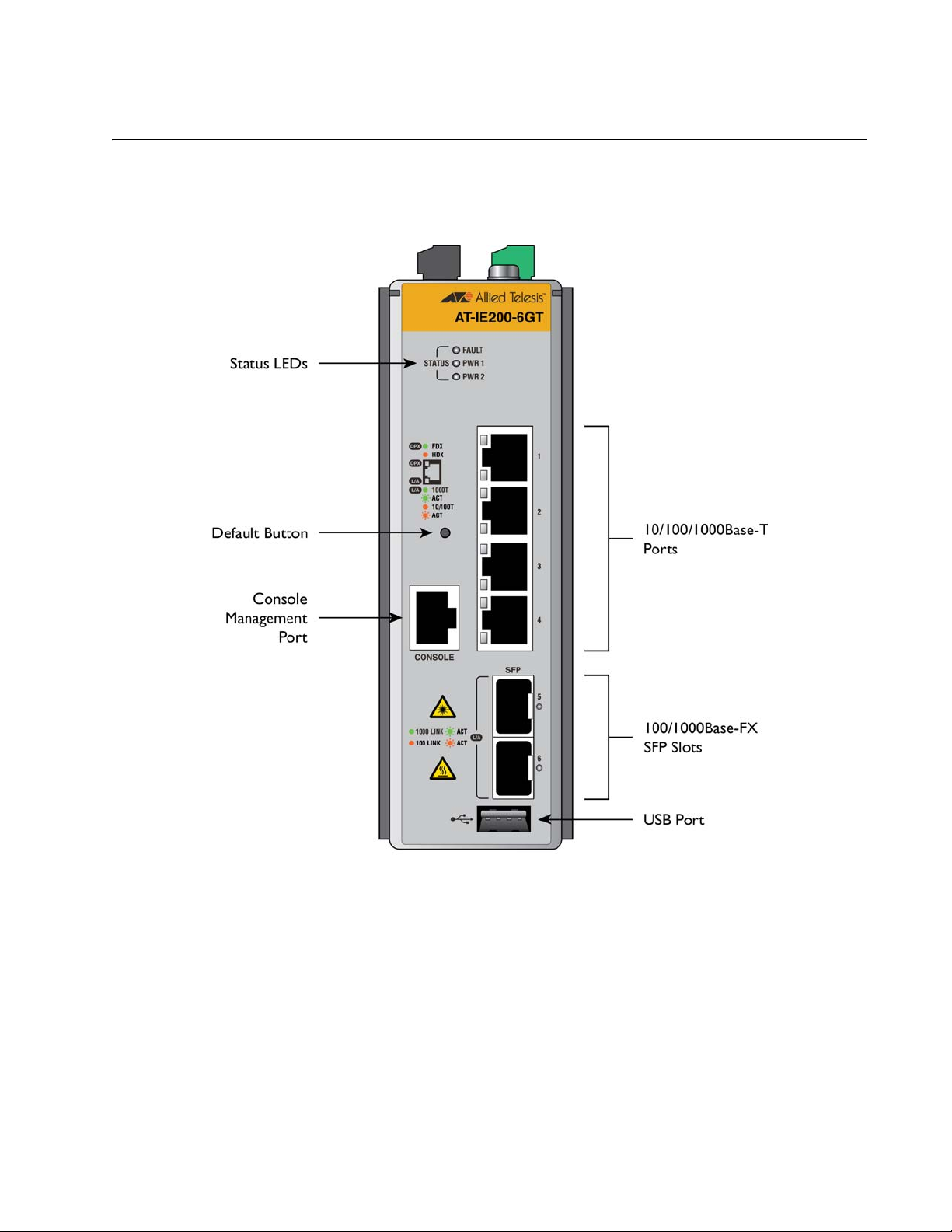
Figure 1 shows the front panel of the AT-IE200-6GT model. The AT-IE200-6FT model is functionally
equivalent, but includes 10/100Base-T twisted pair ports.
Figure 1: Front panel of the AT-IE200-6GT switch.
AT-IE200 Series Installation Guide 17
Page 18
Chapter 1: Overview
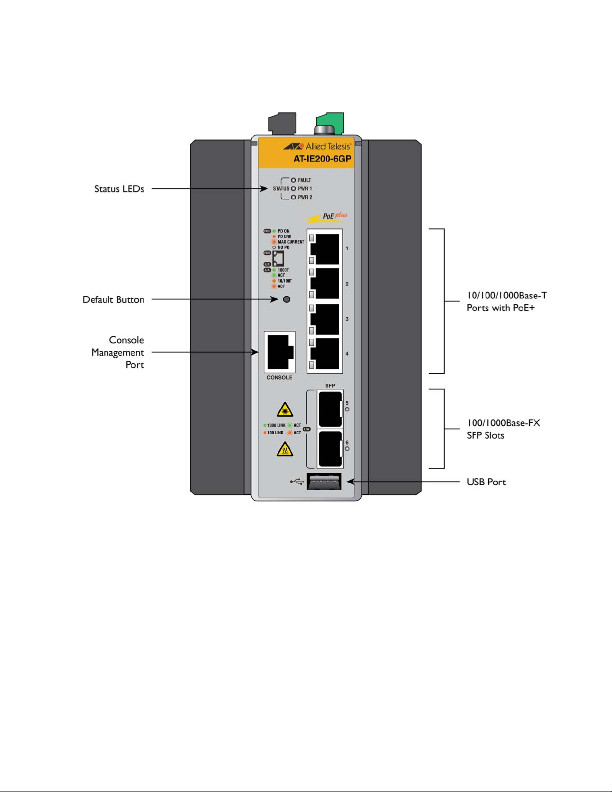
Figure 2 shows the front panel of the AT-IE200-6GP model. The AT-IE200-6FP model is functionally
equivalent, but includes 10/100Base-T twisted pair ports.
Figure 2: Front panel of the AT-IE200-6GP switch.
AT-IE200 Series Installation Guide 18
Page 19
Chapter 1: Overview
Top Panels
Figure 3 shows the top panel of the AT-IE200-6GT and AT-IE200-6FT models. Figure 4 shows the top panel
of the AT-IE200-6GP and AT-IE200-6FP models.
Figure 3: Top panel of the AT-IE200-6GT and AT-IE200-6FT switches.
AT-IE200 Series Installation Guide 19
Page 20

Chapter 1: Overview
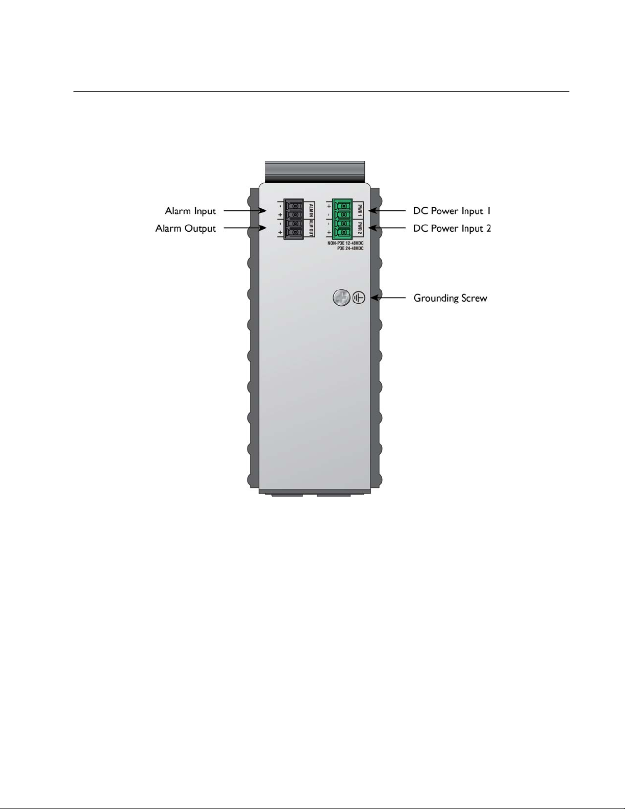
Figure 4: Top panel of the AT-IE200-6GP and AT-IE200-6FP switches.
AT-IE200 Series Installation Guide 20
Page 21

Chapter 1: Overview
Note
10/100Base-T Twisted Pair Ports
The AT-IE200-6FT and AT-IE200-6FP switches have four 10/100Base-T ports.
Speed
The ports can operate at either 10 or 100 Mbps. The speeds may be set manually using the management
software or automatically with Auto-Negotiation (IEEE 802.3u), the default setting.
Duplex Mode
The twisted pair ports can operate in either half- or full-duplex mode. The duplex mode determines the
manner in which a port transmits data. A port set to half-duplex can either transmit or receive data at one
time, while a port operating in full-duplex can transmit and receive data at the same time. The best network
performance is achieved with the full-duplex setting, but not all network equipment is designed to support
that duplex mode.
The duplex modes, like port speeds, may be set manually using the management software or automatically
with Auto-Negotiation (IEEE 802.3u), the default setting.
The speed and duplex mode settings of a port may be set independently of each other. For example, a port
may be configured such that its speed is set manually while its duplex mode is established through AutoNegotiation.
A switch port that is connected to a network device that does not support Auto-Negotiation and has
a fixed duplex mode of full-duplex should not set its duplex mode with Auto-Negotiation. A duplex-
mode mismatch in which a switch port and a network device operate at different duplex modes, may
occur. The duplex modes of switch ports that are connected to network devices that do not support
Auto-Negotiation should be set manually through the management software.
Wiring Configuration
The wiring configuration of a port can be MDI or MDI-X. The wiring configurations of a switch port and a
network device connected with straight-through twisted pair cabling have to be opposite, such that one
device is using MDI and the other MDI-X. For instance, a switch port has to be set to MDI-X if it is connected
to a network device set to MDI.
You may set the wiring configurations of the ports manually or let the switch configure them automatically
with auto-MDI/MDI-X (IEEE 802.3ab-compliant). This feature enables the switch to negotiate with network
devices to establish the proper settings, so that the ports on the devices are using different wiring
configurations.
Maximum Distance
The ports have a maximum operating distance of 100 meters (328 feet).
AT-IE200 Series Installation Guide 21
Page 22

Chapter 1: Overview
Power Over Ethernet
The 10/100Base-T ports on the AT-IE200-6FP switch support Power over Ethernet (PoE), which is a standard
whereby DC power is provided by the switch to network devices over the network twisted pair cables. The
switches support PoE (IEEE 802.3af) and PoE+ (IEEE 802.3at). For more information, refer to “Power Over
Ethernet” on page 26.
Cable Requirements
The cable requirements of the ports are given in Table 1.
Table 1: Twisted Pair Cable Requirements for the 10/100Base-T Ports
10Mbps 100Mbps
Cable Type
Non-PoE PoE PoE+ Non-PoE PoE PoE+
Standard TIA/EIA 568-B-compliant
Category 3 shielded or unshielded
cabling with 100 ohm impedance
and a frequency of 16 MHz.
Standard TIA/EIA 568-A-compliant
Category 5 shielded or unshielded
cabling with 100 ohm impedance
and a frequency of 100 MHz.
Standard TIA/EIA 568-B-compliant
Enhanced Category 5 (Cat 5e)
shielded or unshielded cabling with
100 ohm impedance and a
frequency of 100 MHz.
Standard TIA/EIA 568-B-compliant
Category 6 or 6a shielded cabling.
YesNoNoYesNoNo
Yes Yes No Yes Yes No
Yes Yes Yes Yes Yes Yes
Yes Yes Yes Yes Yes Yes
Port Pinouts
Refer to Table 17 on page 69 for the port pinouts of the 10/100Base-T twisted pair ports.
AT-IE200 Series Installation Guide 22
Page 23

Chapter 1: Overview
Note
Note
10/100/1000Base-T Twisted Pair Ports
The AT-IE200-6GT and AT-IE200-6GP switches have four 10/100/1000Base-T ports.
Speed
The ports can operate at 10, 100, or 1000 Mbps. You can set the speed manually by using the management
software or automatically with Auto-Negotiation (IEEE 802.3u), the default setting.
The ports must be set to Auto-Negotiation to function at 1000 Mbps. They are not compatible with
devices that are not IEEE 802.3u compliant.
Duplex Mode
The twisted pair ports can operate in either half- or full-duplex mode. The duplex modes, like port speeds,
may be set manually using the management software or automatically with Auto-Negotiation (IEEE 802.3u),
the default setting.
You can set the speed and duplex mode settings of a port independently of each other. For example, a port
may be configured such that its speed is set manually while its duplex mode is established through AutoNegotiation.
A switch port that is connected to a network device that does not support Auto-Negotiation and has
a fixed duplex mode of full-duplex should not set its duplex mode with Auto-Negotiation. A duplex-
mode mismatch in which a switch port and a network device operate at different duplex modes, may
occur. The duplex modes of switch ports that are connected to network devices that do not support
Auto-Negotiation should be set manually through the management software.
Wiring Configuration
The wiring configuration of a port operating at 10 or 100 Mbps can be MDI or MDI-X. The wiring
configurations of a switch port and a network device connected with straight-through twisted pair cabling
have to be opposite, such that one device is using MDI and the other MDI-X. For instance, a switch port has
to be set to MDI-X if it is connected to a network device set to MDI.
You may set the wiring configurations of the ports manually or let the switch configure them automatically
with auto-MDI/MDI-X (IEEE 802.3ab-compliant). This feature enables the switch to automatically negotiate
with network devices to establish the proper settings.
The MDI and MDI-X settings do not apply when the ports are operating at 1000 Mbps.
AT-IE200 Series Installation Guide 23
Page 24

Chapter 1: Overview
Maximum Distance
The ports have a maximum operating distance of 100 meters (328 feet).
Power Over Ethernet
The 10/100/1000Base-T ports on the AT-IE200-6GP switch support Power over Ethernet (PoE), which is a
standard whereby DC power is provided by the switch to network devices over the network twisted pair
cables. The switches support PoE (IEEE 802.3af) and PoE+ (IEEE 802.3at). For more information, refer to
“Power Over Ethernet” on page 26.
Cable Requirements
The cable requirements of the ports are given inTable 2.
Table 2: Twisted Pair Cable Requirements for the 10/100/1000Base-T Ports
Cable Type 10Mbps 100Mbps 1000Mbps
Standard TIA/EIA 568-B-compliant
Category 3 shielded or unshielded
cabling with 100 ohm impedance
and a frequency of 16 MHz.
Standard TIA/EIA 568-A-compliant
Category 5 or TIA/EIA 568-Bcompliant Enhanced Category 5
(Cat 5e) shielded or unshielded
cabling with 100 ohm impedance
and a frequency of 100 MHz.
Standard TIA/EIA 568-B-compliant
Category 6 or 6a shielded cabling.
Yes Yes No
Yes Yes Yes
Yes Yes Yes
Port Pinouts
Refer to Table 18 on page 69 for the port pinouts of the 10/100/1000Base-T twisted pair ports.
AT-IE200 Series Installation Guide 24
Page 25

Chapter 1: Overview
SFP Slots
The switches have two slots for 100M/1G MSA compliant fiber optic based SFP modules. The transceivers
can be used to connect the switches to other network devices over large distances, build a high-speed
backbone network between network devices, or connect high-speed devices, such as servers, to your
network.
The switches support a variety of short and long distance, 100 and 1000 Mbps fiber optic SFP modules. For a
list of supported SFP modules, contact your Allied Telesis representative or visit our web site.
AT-IE200 Series Installation Guide 25
Page 26

Chapter 1: Overview
Power Over Ethernet
The AT-IE200-6GP and AT-IE200-6FP switches feature Power over Ethernet (PoE) on the 10/100Base-T or
10/100/1000Base-T ports. PoE is used to supply power to network devices over the same twisted pair cables
that carry the network traffic.
One of the advantages of PoE is that it makes it easier to install a network. The placement of network devices
is often limited by whether there are power sources nearby. This often limits equipment placement or
requires the added time and cost of having additional electrical sources installed. But with PoE, you can install
PoE-compatible devices wherever they are needed without having to worry about whether there are power
sources nearby.
A device that provides PoE to other network devices is referred to as power sourcing equipment (PSE). The
switches act as PSE units by adding DC power to the network cable, thus functioning as a central power
source for other network devices.
Devices that receive their power from a PSE are called powered devices (PD). Examples include wireless access
points, IP telephones, webcams, and even other Ethernet switches.
The switch automatically determines whether or not a device connected to a port is a powered device. Ports
that are connected to network nodes that are not powered devices (that is, devices that receive their power
from another power source) function as regular Ethernet ports, without PoE. The PoE feature remains
activated on the ports but no power is delivered to the devices.
PoE Standards
The AT-IE200-6GP and AT-IE200-6FP switches support these PoE standards:
PoE (IEEE 802.3af): This standard provides up to 15.4 watts at the switch port to
support powered devices that require up to 12.95 watts.
PoE+ (IEEE 802.3at): This standard provides up to 30.0 watts at the switch port to
support powered devices that require up to 25.5 watts.
Powered Device Classes
Powered devices are grouped into the five classes listed in Table 3. The classes are based on the amount of
power the devices require. The switches support all five classes.
Table 3: IEEE Powered Device Classes
Class
0 15.4W 0.44W to 12.95W
1 4.0W 0.44W to 3.84W
2 7.0W 3.84W to 6.49W
AT-IE200 Series Installation Guide 26
Maximum Power Output
from a Switch Port
PD Power Range
Page 27

Chapter 1: Overview
Table 3: IEEE Powered Device Classes
Class
Maximum Power Output
from a Switch Port
PD Power Range
3 15.4W 6.49W to 12.95W
4 30.0W 12.95W to 25.5W
Power Budget
The AT-IE200-6GP and AT-IE200-6FP switches have a PoE power budget of 120 watts. This is the maximum
amount of power the switches can provide at one time to the powered devices.
The power requirements of the PoE devices determine the maximum number of devices the switch can
support at one time. So long as the total power requirements of the powered devices is less than the power
budget of the switch, the switch can supply power to all of the devices. If the total power requirements
exceed the power budget, the switch denies power to one or more ports using a mechanism referred to as
port prioritization.
To determine whether the power requirements of the PoE devices you plan to connect to the switch exceed
its power budget, refer to their documentation for their power requirements and add the requirements
together. The switch should be able to power all of the devices simultaneously as long as the total is below its
power budget. If the total exceeds the available power budget, you should consider reducing the number of
PoE devices so that all of the devices receive power. Otherwise, the switch powers a subset of the devices,
based on port prioritization.
The switch can handle different power requirements on different ports. This enables you to connect different
classes of PoE equipment to the ports on the switch.
Port Prioritization
If the power requirements of the powered devices exceed the switch’s power budget, the switch denies
power to some ports based on a system called port prioritization. You may use this mechanism to ensure
that powered devices critical to the operations of your network are given preferential treatment by the
switch in the distribution of power should the demands of the devices exceed the available capacity.
There are three priority levels:
Critical
High
Low
Ports set to the Critical level, the highest priority level, are guaranteed power before any of the ports
assigned to the other two priority levels. Ports assigned to the other priority levels receive power only if all
the Critical ports are receiving power. Ports that are connected to your most critical powered devices
should be assigned to this level. If there is not enough power to support all the ports set to the Critical
priority level, power is provided to the ports based on port number, in ascending order.
The High level is the second highest level. Ports set to this level receive power only if all the ports set to the
AT-IE200 Series Installation Guide 27
Page 28

Chapter 1: Overview
Critical level are already receiving power. If there is not enough power to support all of the ports set to the
High priority level, power is provided to the ports based on port number, in ascending order.
The lowest priority level is Low. This is the default setting. Ports set to this level only receive power if all of
the ports assigned to the other two levels are already receiving power. As with the other levels, if there is not
enough power to support all of the ports set to the Low priority level, power is provided to the ports based
on port number, in ascending order.
Power allocation is dynamic. Ports supplying power to powered devices may cease power transmission if the
switch’s power budget is at maximum usage and new powered devices, connected to ports with higher
priorities, become active.
Wiring Implementation
The IEEE 802.3af standard defines two methods by which a PSE, such as the switch, can transmit DC power
over twisted pair cables to PDs. These methods, known as modes A and B, identify the wire strands the
switch should use when sending DC power to a PD.
Twisted pair cabling typically consists of eight strands. With 10Base-T and 100Base-T devices, the strands
connected to pins 1, 2, 3, and 6 on the RJ-45 connectors carry the network traffic while strands connected to
pins 4, 5, 7, and 8 are unused. With 1000Base-T devices, all eight strands are used to carry network data.
It takes four strands to deliver DC power to a PD. With Mode A, the power is delivered on pins 1, 2, 3, and
6. These are the same pins in 10Base-T and 100Base-T devices that carry the network data. With mode B,
the power is provided over the spare strands.
The ports on the AT-IE200-6GP and AT-IE200-6FP switches deliver the power using pins 4, 5, 7, and 8, which
corresponds to Mode A in the IEEE 802.3af standard.
Powered devices that comply with the IEEE 802.3af standard are required to support both power delivery
methods. Legacy devices that do not comply with the standard will work with the switch if they are powered
on pins 1, 2, 3, and 6.
AT-IE200 Series Installation Guide 28
Page 29

Chapter 1: Overview
Caution
Alarms
The IE200 contains two alarm ports: One for alarm input and one for alarm output.
To connect either the alarm input or alarm output, use 24 to 18 AWG cable properly rated for the
deployment environment. The maximum length of an alarm cable is two meters.
An alarm cable must be contained within the cabinet (for cabinet applications), or within the building. Do not
expose an alarm cable to the outside environment.
Alarm Input
You can connect the alarm input to a dry contact switch, such as a door switch. There are no polarity
requirements if the port is connected to a non-powered mechanical switch.
Do not apply external power to any of the alarm input’s leads.
Alarm Output
The alarm output can sync 10 mA of current at a maximum voltage of 48V DC. You must provide a series
resistance that will limit the current accordingly.
Connect the RELAY_OUT_RTN pin, connector pin 3, to the negative side of the alarm load.
Connect the RELAY_OUT pin, connector pin 4, to the positive side of the alarm load.
AT-IE200 Series Installation Guide 29
Page 30

Chapter 1: Overview
LEDs
The switch contains LEDs to report device status and link/activity port LEDs.
Status LEDs
The STATUS LEDs include the FAULT, PWR 1 and PWR 2 LEDs.
Figure 5: Status LEDs
Table 4: SFP Link/Activity LED Descriptions
LED Status Description
FAULT Off The switch is receiving power and operating
normally.
Solid red The system is booting up.
5 flashes followed by a
pause
6 flashes in 2 seconds Indicates the switch’s temperature has
PWR1 Off The switch is not receiving power on the PWR
Solid green The switch is receiving DC power from the
PWR 2 Off The switch is not receiving power on the PWR
Indicates the presence of an active alarm. Use
the SHOW FACILITY-ALARM STATUS
command to view active alarms.
exceeded the recommended threshold and the
system is overheating.
1 input or the input power is operating outside
the normal range.
PWR 1 input and is operating normally.
2 input or the input power is operating outside
the normal range.
Solid green The switch is receiving DC power from the
PWR 2 input and is operating normally.
AT-IE200 Series Installation Guide 30
Page 31

Chapter 1: Overview
Twisted Pair Port LEDs
The twisted pair ports each contain two LEDs. The bottom LED indicates link/activity status on all models.
On the AT-IE200-6GT and AT-IE200-6FT models, the top LED indicates duplex mode. On the AT-IE200-6GP
and AT-IE200-6FP models, the top LED indicates PoE status.
Figure 6 shows the port LEDs on the AT-IE200-6GT and AT-IE200-6FT models.
Figure 6: Port LEDs on the AT-IE200-6FT and AT-IE200-6GT switches.
Table 5: Port LED Descriptions for the AT-IE200-6GT and AT-IE200-6FT Switches
LED Status Description
Duplex Mode Off The port is not operating in duplex mode or
the LEDs are turned off. To turn on the LEDs,
use the NO ECOFRIENDLY LED command.
Solid green The port is operating in full duplex mode.
Solid amber The port is operating in half duplex mode.
AT-IE200 Series Installation Guide 31
Page 32

Chapter 1: Overview
Table 5: Port LED Descriptions for the AT-IE200-6GT and AT-IE200-6FT Switches (Continued)
LED Status Description
Link/Activity Off The port has not established a link with
another network device or the LEDs are
turned off. To turn on the LEDs, use the NO
ECOFRIENDLY LED command.
Solid green The port has established a 100 Mbps (AT-
IE200-6FT) or 1000 Mbps (AT-IE200-6GT) link
to a network device.
Flashing green The port is transmitting or receiving data at
100 Mbps (AT-IE200-6FT) or 1000 Mbps (ATIE200-6GT).
Solid amber The port has established a 10 Mbps (AT-IE200-
6FT) or 10/100 Mbps (AT-IE200-6GT) link to a
network device.
Flashing amber The port is transmitting or receiving data at 10
Mbps (AT-IE200-6FT) or 10/100 Mbps (ATIE200-6GT).
Figure 7 shows the port LEDs on the AT-IE200-6GP and AT-IE200-6FP models.
Figure 7: Port LEDs on the AT-IE200-6FP and AT-IE200-6GP switches.
AT-IE200 Series Installation Guide 32
Page 33

Chapter 1: Overview
Table 6: Port LED Descriptions for the AT-IE200-6GP and AT-IE200-6FP Switches
PoE Off Indicates one of the following:
LED Status Description
The port is not connected to a powered
device (PD).
The PD is powered off.
The port is disabled in the management
software.
PoE is disabled on the port.
The LEDs are turned off. To turn on the
LEDs, use the NO ECOFRIENDLY LED
command.
Solid green A PD is receiving power from the port.
Solid amber The switch has shut down PoE+ on the port
due to a fault condition.
Flashing amber The switch is detecting a PD on the port but is
not delivering power to it because the
maximum power budget has been reached
Link/Activity Off The port has not established a link with
another network device or the LEDs are
turned off. To turn on the LEDs, use the NO
ECOFRIENDLY LED command.
Solid green The port has established a 100 Mbps (AT-
IE200-6FP) or 1000 Mbps (AT-IE200-6GP) link
to a network device.
Flashing green The port is transmitting or receiving data at
100 Mbps (AT-IE200-6FP) or 1000 Mbps (ATIE200-6GP).
Solid amber The port has established a 10 Mbps (AT-IE200-
6FP) or 10/100 Mbps (AT-IE200-6GP) link to a
network device.
Flashing amber The port is transmitting or receiving data at 10
Mbps (AT-IE200-6FP) or 10/100 Mbps (ATIE200-6GP).
SFP LEDs
The SFP LEDs are located to the right of the slots. Each slot has one LED that indicates the speed and link/
activity status of the SFP.
AT-IE200 Series Installation Guide 33
Page 34

Chapter 1: Overview
Figure 8: SFP Link/Activity LEDs.
Table 7 describes the Link/Activity LEDs for the SFP slots.
Table 7: SFP Link/Activity LED Descriptions
LED Status Description
Off The slot is empty, the SFP transceiver
has not established a link to a network
device, or the LEDs are turned off. To turn on
the LEDs, use the NO ECOFRIENDLY LED
command.
Solid green The SFP has established a link to a network
device at 1 Gbps, but is not transmitting or
receiving network packets.
Flashing green The SFP transceiver is transmitting or receiving
network packets at 1 Gbps.
Solid amber The SFP has established a link to a network
device at 100 Mbps, but is not transmitting or
receiving network packets.
Flashing amber The SFP transceiver is transmitting or receiving
network packets at 100 Mbps.
AT-IE200 Series Installation Guide 34
Page 35

Chapter 1: Overview
Note
Console Port
The console port is used to configure the features and parameter settings of the switch. This type of
management uses serial RS-232 and is commonly referred to as local or out-of-band management because it
is not conducted over your network. To perform local management, you must be at the location of the
switch and use a cable that has RJ-45 RJ-style (8P8C) and DB-9 (D-sub 9-pin) connectors.
To establish a local management session with the switch, connect a terminal or a personal computer with a
terminal emulation program to the console port, which has an RJ-45 style (8P8C) connector.
The console port is set to the following specifications:
Default baud rate: 9600 bps (range is 9600 to 115200 bps)
Data bits: 8
Parity: None
Stop bits: 1
Flow control: None
These settings are for a DEC VT100 or ANSI terminal, or an equivalent terminal emulation program.
AT-IE200 Series Installation Guide 35
Page 36

Chapter 1: Overview
Warning
Power Supplies
IE200 models have connections for inputs from two separate DC power sources on the top panel.
Connecting two separate DC sources to the switch provides power redundancy and protects against
interruptions to network operations in the event one power input fails. Power redundancy is available only
when both DC power connections are connected to power sources.
The AT-IE200-6GP and AT-IE200-6FP models operate in a load sharing manner. Each external DC power
supply must be capable of sourcing 155W over the operating temperature range.
Refer to Appendix A, “Technical Specifications” on page 66 for the input voltage range.
Power connector is used as a disconnection device. To de-energize equipment, unplug the power
connector from the unit.
AT-IE200 Series Installation Guide 36
Page 37

Chapter 2
Beginning the Installation
This chapter contains the safety precautions and guidelines for selecting a site for the switch. The chapter
contains the following sections:
“Reviewing Safety Precautions” on page 38
“Selecting a Site for the Switch” on page 41
“Unpacking the Switch” on page 42
AT-IE200 Series Installation Guide 37
Page 38

Chapter 2: Beginning the Installation
Note
Warning
Warning
Warning
Warning
Warning
Reviewing Safety Precautions
Review the following safety precautions before you install the switch.
The indicates that a translation of the safety statement is available in a PDF document titled
“Translated Safety Statements” (613-000405) on the Allied Telesis website at
http://www.alliedtelesis.com.
Class 1 Laser product. L1
Do not stare into the laser beam. L2
Do not look directly at the fiber optic cable ends or inspect the cable ends with an optical lens. L6
For all Allied Telesis approved SFP models:
Laser Radiation.
Do not view directly with optical instruments.
Class 1 Laser product.
Rayonnement Laser.
Ne pas observer directement à l’aide d’instruments d’optique.
Appareil à Laser de classe 1.
To prevent electric shock, do not remove the cover. No userserviceable parts inside. This unit
contains hazardous voltages and should only be opened by a trained and qualified technician. To avoid
the possibility of electric shock, disconnect electric power to the product before connecting or
disconnecting the LAN cables. E1
AT-IE200 Series Installation Guide 38
Page 39

Chapter 2: Beginning the Installation
Warning
Warning
Warning
Note
Caution
Note
Warning
Warning
Caution
Do not work on equipment or cables during periods of lightning activity. E2
Power cord is used as a disconnection device. To de-energize the equipment, unplug the power
connector from the unit.
This equipment must be earthed. The ground lug on the switch must be connected to a properly
earthed bonding point.
Ground resistance from the building primary bonding point to earth should be less than 25 ohms.
A minimum of 4 inches open space shall be provided underneath the unit.
A minimum of 8 inches open space shall be provided on top of the unit.
A minimum of 4 inches open space shall be provided in front of the unit.
A minimum of 1” distance shall be kept between the sides of the unit and adjacent equipment.
All Countries: Install product in accordance with local and National Electrical Codes. E8
Operating Temperature. Maximum ambient temperature is installation dependent. Please see
“Environmental Specifications” on page 67 for details.
Only trained and qualified service personnel are allowed to install or to replace this equipment.
Circuit Overloading: Consideration should be given to the connection of the equipment to the supply
circuit and the effect that overloading of circuits might have on over current protection and supply
wiring. Appropriate consideration of equipment nameplate ratings should be used when addressing this
concern. E21
AT-IE200 Series Installation Guide 39
Page 40

Chapter 2: Beginning the Installation
Warning
Caution
Warning
Warning
Warning
Note
Warning
This unit might have more than one power cord. To reduce the risk of electric shock, disconnect all
power cords before servicing the unit. E30
The unit does not contain serviceable components. Please return damaged units for servicing. E42
This equipment shall be installed in a Restricted Access location. E45
When the unit is operational it will be hot. Exercise caution when handling with unprotected hands.
Per NEC section 800.90 all exposed cables, service wires, or drops when entering a building must have
primary over voltage protection if they are classified as exposed plant.
This equipment meets EN61000-4-5 Class 3 on the DC input and Class 2 on the ETHERNET I/O lines.
Allied Telesis does not warrant against lightening or power surges causing damage to the device. Such
damage will be the responsibility of the equipment owner.
AT-IE200 Series Installation Guide 40
Page 41

Chapter 2: Beginning the Installation
Selecting a Site for the Switch
The switch is designed for standalone or DIN rail mounting. Observe the following general requirements
when choosing a site for the switch:
Install the switch close to the DC power supplies
Verify that the site provides easy access to the ports on the front of the switch. This will
make it easy to connect and disconnect cables, as well as view the port LEDs.
Check that the site allows for adequate air flow around the unit and through its vents on
the top and bottom. Air vents should not be restricted so that the switch can maintain
adequate cooling.
Do not place objects on top of the switch.
Do not expose the switch to moisture or water.
You should use dedicated power circuits or power conditioners to supply reliable
electrical power to the network devices.
AT-IE200 Series Installation Guide 41
Page 42

Chapter 2: Beginning the Installation
Note
Unpacking the Switch
The following items come with the switch. If any item is missing or damaged, contact your Allied Telesis sales
representative for assistance.
Retain the original packaging material in the event you need to return the unit to Allied Telesis.
Two wall mounting brackets
Five bracket screws
AT-IE200 Series Installation Guide 42
Page 43

Chapter 3
Installing the Switch on a DIN Rail or Wall Mount
This chapter contains the following sections:
“Installing the Switch on a DIN Rail” on page 44
“Installing the Switch on a Wall Mount” on page 46
AT-IE200 Series Installation Guide 43
Page 44

Chapter 3: Installing the Switch on a DIN Rail or Wall Mount
Installing the Switch on a DIN Rail
Observe the following requirements when choosing a DIN rail site for your switch:
The DC PSU(s) should be located near the switch and be easily accessible.
The site should allow for easy access to the ports on the front of the switch, so that you
can easily connect and disconnect cables, and view the port LEDs.
The site should allow for adequate air flow around the unit and through the cooling fins.
The site should not expose the switch to moisture or water.
The site should be a dust-free environment.
The site should include dedicated power circuits or power conditioners to supply
reliable electrical power to the network devices.
To install the switch on the DIN rail, hook the switch’s mounting bracket onto the DIN rail and rotate the
switch down to snap it into place.
Figure 9: Attaching the switch to a DIN rail.
AT-IE200 Series Installation Guide 44
Page 45

Chapter 3: Installing the Switch on a DIN Rail or Wall Mount
After snapping the switch onto the DIN rail, go to Chapter 4, “Cabling the Networking Ports” on page 48 to
connect the network cables to the ports on the switch.
AT-IE200 Series Installation Guide 45
Page 46

Chapter 3: Installing the Switch on a DIN Rail or Wall Mount
Installing the Switch on a Wall Mount
To install the switch on a wall mount:
1. Mount a piece of ¾-inch plywood to the wall. The plywood must be securely mounted to the wall using
appropriate methods based on the wall surface.
2. Attach the wall mount brackets to the unit with four screws, as shown in Figure 10.
Figure 10: Attaching the wall mount brackets.
3. Fasten the switch to the wall with #8 x 1.5” pan head wood screws. The distance between the mounting
holes is 175 mm. (6.9 in.), as shown in Figure 11.
AT-IE200 Series Installation Guide 46
Page 47

Chapter 3: Installing the Switch on a DIN Rail or Wall Mount
Figure 11: Spacing between mounting holes.
AT-IE200 Series Installation Guide 47
Page 48

Chapter 4
Cabling the Networking Ports
This chapter contains the following sections:
“Cabling the Twisted Pair Ports” on page 49
“Installing SFP Transceivers” on page 51
AT-IE200 Series Installation Guide 48
Page 49

Chapter 4: Cabling the Networking Ports
Cabling the Twisted Pair Ports
The guidelines for cabling the 10/100Base-T and 10/100/1000Base-T twisted pair ports are:
The cable specifications for the 10/100Base-T and 10/100/1000Base-T twisted pair ports
are listed in Table 1 on page 22 and Table 2 on page 24, respectively.
The connectors on the cables should fit snugly into the ports, and the tabs should lock
the connectors into place.
The default setting for the wiring configurations of the ports is auto-MDI/MDI-X. The
default setting is appropriate for switch ports that are connected to 10/100Base-T
network devices that also support auto-MDI/MDI-X.
The default auto-MDI/MDI-X setting is not appropriate for switch ports that are
connected to 10/100Base-T network devices that do not support auto-MDI/MDI-X and
have a fixed wiring configuration. For switch ports connected to those types of network
devices, you should disable auto-MDI/MDI-X and set the wiring configurations manually.
The appropriate MDI/MDI-X setting for a switch port connected to a 10/100Base-T
network device with a fixed wiring configuration depends on the setting of the network
device and whether the switch and network device are connected with straight-through
or crossover cable. If you are using straight-through twisted pair cable, the wiring
configurations of a port on the switch and a port on a network device must be opposite
each other, such that one port uses MDI and the other MDI-X. For example, if a
network device has a fixed wiring configuration of MDI, you must disable auto-MDI/
MDI-X on the corresponding switch port and manually set it to MDI-X. If you are using
crossover twisted pair cable, the wiring configurations of a port on the switch and a port
on a network device must be the same.
The default speed setting for the ports is Auto-Negotiation. This setting is appropriate
for ports connected to network devices that also support Auto-Negotiation.
The default speed setting of Auto-Negotiation is not appropriate for ports connected to
10/100Base-T network devices that do not support Auto-Negotiation and have fixed
speeds. For those switch ports, you should disable Auto-Negotiation and set the port’s
speed manually to match the speeds of the network devices.
The 10/100/1000Base-T ports must be set to Auto-Negotiation, the default setting, to
operate at 1000Mbps.
The default duplex mode setting for the ports is Auto-Negotiation. This setting is
appropriate for ports connected to network devices that also support Auto-Negotiation
for duplex modes.
The default duplex mode setting of Auto-Negotiation is not appropriate for ports
connected to network devices that do not support Auto-Negotiation and have a fixed
duplex mode. You should disable Auto-Negotiation on those ports and set their duplex
modes manually to avoid the possibility of duplex mode mismatches. A switch port using
Auto-Negotiation defaults to half duplex if it detects that the end node is not using
Auto-Negotiation, which can result in a mismatch if the end node is operating at a fixed
duplex mode of full-duplex.
If the Ethernet cables will be connected to equipment that is located outdoors, such as a
AT-IE200 Series Installation Guide 49
Page 50

Chapter 4: Cabling the Networking Ports
CCTV mounted on a pole, the cables will be subjected to surge from lightning or power
cross events. A properly rated primary protection device must be installed on the cable
prior to connection to the switch.
AT-IE200 Series Installation Guide 50
Page 51

Chapter 4: Cabling the Networking Ports
Installing SFP Transceivers
General guidelines for installing SFP transceivers are:
SFP transceivers are hot-swappable. You may install them while the switch is powered
on.
Your Allied Telesis sales representative can provide you with a list of supported
transceivers for the units.
The operational specifications and fiber optic cable requirements of the transceivers are
provided in the documents included with the devices.
You should install a transceiver before connecting the fiber optic cable.
Fiber optic transceivers are dust sensitive. Always keep the plug in the optical bores
when a fiber optic cable is not installed, or when you store the transceiver. When you
do remove the plug, keep it for future use.
Unnecessary removal and insertion of a transceiver can lead to premature failure.
The SFP cages on the switch use an internal heat sink that requires an additional amount
of force to remove and install an SFP module.
To install an SFP transceiver:
1. Remove the dust plug from a transceiver slot on the switch.
Figure 12: Removing the dust plug from an SFP slot.
AT-IE200 Series Installation Guide 51
Page 52

Chapter 4: Cabling the Networking Ports
2. Remove the transceiver from its shipping container and store the packaging material in a safe location.
3. Position the transceiver with the Allied Telesis label facing to the right.
4. Slide the transceiver into the slot until it clicks into place.
Figure 13: Installing an SFP transceiver.
5. Remove the dust cover from the transceiver module.
AT-IE200 Series Installation Guide 52
Page 53

Chapter 4: Cabling the Networking Ports
Figure 14: Removing the dust cover from an SFP transceiver.
6. Verify that the handle of the transceiver is in the right-hand position.
7. Connect the fiber optic cable to the transceiver. The connector on the cable should fit snugly into the
port and the tab should lock the connector into place.
AT-IE200 Series Installation Guide 53
Page 54

Chapter 4: Cabling the Networking Ports
Figure 15: Connecting a fiber optic cable to an SFP transceiver.
Repeat the procedure to install a second SFP transceiver.
AT-IE200 Series Installation Guide 54
Page 55

Chapter 5
Powering on the Switch
This chapter contains the following sections:
“Connecting the Power” on page 56
“Connecting the Ground Wiring” on page 57
“Monitoring the Initialization Processes” on page 58
“Starting a Management Session” on page 59
“Starting a Local Management Session” on page 61
“Specifying Ports in the Command Line Interface” on page 62
AT-IE200 Series Installation Guide 55
Page 56

Chapter 5: Powering on the Switch
Note
Note
Connecting the Power
Figure 3 on page 19 and Figure 4 on page 20 show the location of the power connector on the top panel of
the switch. The power connector has four positions for connecting two DC power sources.
The power connector on the switch is green. The alarm connector is black.
The switch requires a DC power supply. The power supply requirements for the AT-IE200-6FP and ATIE200-6GP models are:
DC voltage between 24 and 48V DC.
DC voltage shall not exceed 50V.
The DC power supply must be capable of providing 155 watts continuous over the
operating temperature range of -40 to +75 degrees C.
The power supply requirements for the AT-IE200-6FT and AT-IE200-6GT models are:
DC voltage between 12 and 48V DC.
DC voltage shall not exceed 50V.
The DC power supply must be capable of providing 32 watts continuous over the
operating temperature range of -40 to +75 degrees C.
A 24V PSU must have an absolute minimum tolerance of -3% or 23.25V at the input to the switch.
A 48V PSU must have an absolute maximum tolerance of +2.5% or 49.25V at the input to the switch.
The wiring requirements for the switch are:
Use two separate conductors of 18 AWG twisted pair properly rated cable to wire the
DC power supply to the switch.
Stranded cable is recommended.
To wire the power, insert the cable into the terminal block and fasten it securely.
AT-IE200 Series Installation Guide 56
Page 57

Chapter 5: Powering on the Switch
Connecting the Ground Wiring
Figure 3 on page 19 and Figure 4 on page 20 show the location of the grounding screw on the top panel of the
switch. The grounding requirements are:
Use a minimum of #16 AWG solid copper conductor to connect the switch’s grounding
screw to the earth.
Keep the wire length as short as possible.
Continuity from the grounding screw to the earth ground rod must be less than 0.05
ohms.
If a terminal is used, it should be double crimped.
AT-IE200 Series Installation Guide 57
Page 58

Chapter 5: Powering on the Switch
Monitoring the Initialization Processes
You can monitor the bootup sequence by connecting a terminal or computer that has a terminal emulator
program to the console port on the switch.
After the switch has initialized its management software, go to “Starting a Management Session” on page 59.
AT-IE200 Series Installation Guide 58
Page 59

Chapter 5: Powering on the Switch
Starting a Management Session
You can use the following methods and tools to manage the switch:
Local management
Telnet client
Secure shell client
HTTP non-secure and HTTPs secure Web browser
SNMPv1, v2C, v3
Local Management
Local management uses the console port on the switch. It is commonly referred to as out-of-band
management because the management sessions are not conducted over your network. The requirements for
local management are:
A terminal or computer with a terminal emulator program
An RJ-45 management cable
This management method uses the command line interface, which gives you access to all of the features and
parameters on the switch. For instructions on how to start a local management session, refer to “Starting a
Local Management Session” on page 61.
Telnet Management
The switch has a Telnet server. You can use the server to manage the unit over your network with the
Telnet application protocol. It is commonly referred to as in-band management because it is conducted over
the network. The requirements for Telnet management are:
Your management workstation must have a Telnet client.
The Telnet server on the switch must be activated. By default, the Telnet server is
activated.
The switch must have an IP address, either from DHCP or statically assigned.
You must be able to reach the switch from your management workstation.
Telnet management uses the command-line interface, giving you access to all of the features and parameter
settings on the switch.
Telnet management sessions are not secure and are vulnerable to snooping because the packets exchanged
between the switch and your workstation are sent in plain text. The security of the switch may be
jeopardized if an intruder captures the packet containing your username and password. For secure remote
management, see “Secure Shell Management” on page 60.
AT-IE200 Series Installation Guide 59
Page 60

Chapter 5: Powering on the Switch
Secure Shell Management
Secure shell (SSH) management is similar to Telnet management in that you can use it, together with the
command line interface, to manage all of the features and functions of the switch from a workstation on your
network. The difference is that this management method encrypts the packets exchanged by your computer
and the switch to protect your management sessions.
The requirements for SSH management are:
Your management workstation must have an SSH client.
The SSH server on the switch must be activated. The server’s default setting is disabled.
You must create an encryption key on the switch.
The switch must have an IP address, either from DHCP or statically assigned.
You must be able to reach the switch from your management workstation.
For instructions on how to configure the switch for SSH management, refer to the Software Reference for ATIE200 Switches.
Web Browser Management
You can remotely manage the switch with a web browser. A special web browser interface, featuring both
non-secure (HTTP) and secure (HTTPS) operation, lets you monitor and configure many of the switch’s
features from a series of windows. The interface, however, may only be used to configure a subset of the
features. To configure those features the web browser interface does not support, you have to use the
command line interface from another management method.
The requirements for non-secure HTTP web browser management are:
Your management workstation must have a web browser.
The web browser server on the switch is activated by default. This is the default setting
in the default BOOT.CFG and QSTART.CFG files.
The switch must have an IP address, either from DHCP or statically assigned.
You must be able to reach the switch from your management workstation.
Refer to the Software Reference for AT-IE200 Switches for instructions on how to configure the switch for
secure HTTPS web browser management.
SNMP
Refer to the Software Reference for AT-IE200 Switches for instructions on how to configure the switch for
SNMP management. The switch does not have any default SNMP community strings.
AT-IE200 Series Installation Guide 60
Page 61

Chapter 5: Powering on the Switch
Note
Note
Starting a Local Management Session
This procedure requires a terminal or a terminal emulator program and an RJ-45 management cable. To start
a local management session on the switch, perform the following procedure:
1. Connect the RJ-45 connector on the management cable to the console port on the front panel of the
switch.
2. Connect the other end of the cable to an RS-232 port on a terminal or PC with a terminal emulator
program.
3. Configure the terminal or terminal emulator program as follows:
Baud rate: 9600 bps (The baud rate of the console port is adjustable from 1200 to
115200 bps. The default is 9600 bps.)
The BootLoader can only be managed at 9600 bps. If you set the baud rate to 115200 bps the
BootLoader will not work.
Data bits: 8
Parity: None
Stop bits: 1
Flow control: None
The port settings are for a DEC VT100 or ANSI terminal, or an equivalent terminal emulator program.
4. Press Enter. You are prompted for a username and password.
5. Enter the username and password to log on the switch. If this is the initial management session of the
switch, enter “manager” as the user name “friend” as the password. The user name and password are
case sensitive.
The local management session starts when the AlliedWare Plus™ command line prompt is displayed.
For information on the command line interface, refer to the Software Reference for AT-IE200 Switches.
AT-IE200 Series Installation Guide 61
Page 62

Chapter 5: Powering on the Switch
port1.0
.n
Slot ID
Port Number
Stack ID
Specifying Ports in the Command Line Interface
The command line interface of the Local, Telnet, and SSH management methods gives you the ability to
configure all the features and parameters on the switch. Many of the commands have the PORT parameter,
which you use to identify the networking ports on the switch. This parameter has the following format:
The first number is the switch’s stack ID number. This number is always 1 for IE200 switches.
The slot ID value, which is used to specify slot numbers in a multi-module chassis, also does not apply to
IE200 switches and is always 0.
The third value is a port number on the switch. You can specify only one port number in a PORT parameter,
but you can specify more than one PORT parameter in many of the commands where the parameter is
supported.
Here is an example of the PORT parameter. It uses the INTERFACE command to enter the Port Interface
mode for ports 2 and 4:
awplus> enable
awplus# configure terminal
awplus(config)# interface port1.0.2,port1.0.4
You can specify port ranges. This example displays the port settings for ports 1 to 3:
awplus# show interface port1.0.1-port1.0.3
Note that you must include the prefix “port1.0.” in the last number of a range.
For instructions on the command line interface and the PORT parameter, refer to the Software Reference for
AT-IE200 Switches.
AT-IE200 Series Installation Guide 62
Page 63

Chapter 6
Note
Troubleshooting
This chapter contains information on how to troubleshoot the switch if a problem occurs.
For further assistance, please contact Allied Telesis Technical Support at www.alliedtelesis.com/
support.
Problem: The PWR1 and PWR2 LEDs on the front of the switch are off.
Solution:The unit is not receiving power. Try the following:
Verify the power cable is securely fastened in the terminal block.
Verify the DC power supply is providing power by connecting another device to it.
Verify the DC power supply is providing enough power. The AT-IE200-6GT and AT-
IE200-6FT models require a minimum of 12 volts. The AT-IE200-6GP and AT-IE200-6FP
models require a minimum of 24 volts. See “Power Specifications” on page 67 for more
information.
Try connecting the unit to another DC power source.
Try a different power cable.
Verify that the voltage from the power source is within the required levels for your
region.
Problem: A twisted pair port on the switch is connected to a network device but the port’s link/activity LED
is off.
Solution: The port is unable to establish a link to a network device. Try the following:
Verify that the network device connected to the twisted pair port is powered on and is
operating properly.
Verify that the twisted pair cable is securely connected to the port on the switch and to
the port on the remote network device.
Verify that the port is connected to the correct twisted pair cable. This is to eliminate
the possibility that the port is connected to the wrong network device, such as a
powered off device.
Try connecting another network device to the twisted pair port with a different cable. If
the twisted pair port is able to establish a link, then the problem is with the cable or the
other network device.
Verify that the twisted pair cable does not exceed 100 meters (328 feet).
Verify that you are using the appropriate category of twisted pair cable: Category 3 or
better for 10 Mbps operation and Category 5 and Category 5E for 100 and 1000 Mbps
AT-IE200 Series Installation Guide 63
Page 64

Chapter 6: Troubleshooting
Note
operation.
A 1000Base connection may require five to ten seconds to establish a link.
Problem: The link/activity LED for an SFP transceiver is off.
Solution: The fiber optic port on the transceiver is unable to establish a link to a network device. Try the
following:
Verify that the network device connected to the fiber optic port is operating properly.
Verify that the fiber optic cable is securely connected to the port on the switch and to
the port on the remote network device.
Check that the SFP module is fully inserted in the slot.
Verify that the operating specifications of the fiber optic ports on the SFP transceiver
and the remote network device are compatible.
Verify that the correct type of fiber optic cabling is being used.
Verify that the port is connected to the correct fiber optic cable. This is to eliminate the
possibility that the port is connected to the wrong remote network device, such as a
powered off device.
Try connecting another network device to the fiber optic port using a different cable. If
the port is able to establish a link, then the problem is with the cable or with the other
network device.
Use the switch’s management software to verify that the port is enabled.
If the remote network device is a management device, use its management firmware to
determine whether its port is enabled.
Test the attenuation on the fiber optic cable with a fiber optic tester to determine
whether the optical signal is too weak (sensitivity) or too strong (maximum input
power).
Problem: Network performance between a twisted pair port on the switch and a network device is slow.
Solution: There might be a duplex mode mismatch between the port and the network device. This occurs
when a twisted pair port using Auto-Negotiation is connected to a device with a fixed duplex mode of full
duplex. If this is the cause of the problem, adjust the duplex mode of the port on the network device or on
the switch so that both ports are using the same duplex mode.
Problem: A port’s link/activity LED is blinking.
Solution: The link between the port and the network device is intermittent. Try the following:
Connect another network device with a different cable to the port. If the Link LED
remains steady on, then the problem is with the original cable or the network device.
If the problem is with an SFP transceiver, check that the transceiver is fully inserted in
the slot.
AT-IE200 Series Installation Guide 64
Page 65

Chapter 6: Troubleshooting
Problem: The AT-IE200-6FP or AT-IE200-6GP switch is not providing power to a PoE device.
Solution: Try the following:
Review the PD’s documentation to confirm that the device supports Mode A of the IEEE
802.3at standard. Mode A is one of two modes that define the connector pins that
deliver the power from the port on the switch to the PD. In Mode A, the power is
carried on pins 1, 2, 3, and 6 on the RJ-45 port, the same pins that carry the network
traffic. The second mode, Mode B, defines pins 4, 5, 7, and 8 as the power carriers. The
switches do not support Mode B. Most powered devices are designed to accept power
by either mode, but some legacy devices may only support one mode. This can be
verified by reviewing the device’s documentation or data sheet. Legacy devices that only
support Mode B will not work with the switch.
Check that the device’s power requirements do not exceed 30 watts. This can be
verified by reviewing the device’s documentation or data sheet.
Verify that you are using the appropriate category of twisted-pair cable.
Use the management software on the switch to determine whether PoE is enabled on
the port. The default setting for PoE is enabled.
Use the management software on the switch to determine whether the PoE power
setting for the port has been reduced to a value below the power requirements of the
device.
Try connecting the device to a different port on the switch.
AT-IE200 Series Installation Guide 65
Page 66

Appendix A
Technical Specifications
Physical Specifications
Dimensions (W x H x D)
Table 8: Product Dimensions
Weights
Ventilation
AT-IE200-6GT
AT-IE200-6FT
AT-IE200-6GP
AT-IE200-6FP
AT-IE200-6GT
AT-IE200-6FT
AT-IE200-6GP
AT-IE200-6FP
Table 10: Ventilation Requirements for Cabinet Installation
Minimum open space
below
5.5 cm. x 15.9 cm. x 13.4 cm.
(2.17 in. x 6.25 in. x 5.28 in.)
9.5 cm. x 15.9 cm. x 13.4 cm.
(3.74 in. x 6.25 in. x 5.28 in.)
Table 9: Product Weights
0.9 kg. (2.0 lb.)
1.3 kg. (2.5 lb.)
10.2 cm. (4 in.)
Minimum open space
above
Minimum open space
in front
Minimum open space
on sides
AT-IE200 Series Installation Guide 66
20.3 cm. (8 in.)
10.2 cm. (4 in.)
2.5 cm. (1 in.)
Page 67

Appendix A: Technical Specifications
Table 11: Ventilation Requirements for Wall Mount Installation
Minimum open space
around unit (below,
above, front and
sides)
Cabinet Dimensions
Minimum Cabinet
Size
Environmental Specifications
Operating Temperature, Metal
Cabinet
Operating Temperature, Wall Mount -40° C to 70° C (-40° F to 158° F)
61 cm. (24 in.)
Table 12: Cabinet Dimensions
50.8 cm. x 50.8 cm. x 30.5 cm.
(20 in. x 20 in. x 12 in.)
Table 13: Environmental Specifications
-40° C to 75° C (-40° F to 167° F)
Storage Temperature -40° C to 85° C (-40° F to 185° F)
Operating Humidity 5% to 95% noncondensing
Storage Humidity 5% to 95% noncondensing
Operating Altitude Range Up to 3,000 m (9,843 ft)
Maximum Nonoperating Altitude 4,000 m (13,100 ft)
If the switch is installed in an outdoor cabinet that is directly ventilated to outdoor air, the conformally
coated model should be used.
Power Specifications
Maximum Power Consumptions
Table 14: Maximum Power Consumptions
AT-IE200-6GT
AT-IE200-6FT
AT-IE200-6GP
AT-IE200-6FP
32 watts
155 watts
AT-IE200 Series Installation Guide 67
Page 68

Appendix A: Technical Specifications
Note
Input Voltages
Table 15: Input Voltages
AT-IE200-6GT
AT-IE200-6FT
AT-IE200-6GP
AT-IE200-6FP
A 24V PSU must have an absolute minimum tolerance of -3% or 23.25V at the input to the switch.
A 48V PSU must have an absolute maximum tolerance of +2.5% or 49.25V at the input to the switch.
12-48 VDC, 2.5A maximum
24-48 VDC, 7.0A maximum
Certifications
Table 16: Product Certifications
RMI Emissions FCC Part 15B Class A
EN55022:2010 Class A
EN61000-32:2006+A1:2009+A2:2009
EN61000-3-3:2008
VCCI- Class A
RFI Immunity EN55024:2010
Electrical and Laser Safety UL/E/IEC60950-1
All Allied Telesis approved SFP
modules
RJ-45 Twisted Pair Port Pinouts
Figure 16 illustrates the pin layout of the RJ-45 connectors and ports.
EN61000-4-2:2009
EN61000-4-3:2006 + A2:2010
EN61000-4-4:2012
EN61000-4-5:2006
EN61000-4-6:2009
EN61000-4-8:2010
EN61000-4-11:2004
CSA 22.2:60950-1
2006/95/EC Low Voltage Directive
EN60825-1
EN60825-2
EN/IEC/UL60950-1
FCC CDRH registered
AT-IE200 Series Installation Guide 68
Page 69

Appendix A: Technical Specifications
Figure 16: RJ-45 Socket Pin Layout (Front View)
Table 17 lists the pin signals for 10 and 100 Mbps.
Table 17: Pin Signals for 10 and 100 Mbps
Pin MDI Signal MDI-X Signal
1TX+ RX+
2TX- RX-
3RX+ TX+
4 Not used Not used
5 Not used Not used
6RX- TX-
7 Not used Not used
8 Not used Not used
Table 18 lists the pin signals when a port operating at 1000 Mbps.
Table 18: Pin Signals for 1000 Mbps
Pinout Pair
1Pair 1 +
2Pair 1 -
3Pair 2 +
4Pair 3 +
5Pair 3 -
6Pair 2 -
7Pair 4 +
8Pair 4 -
RJ-45 Style Serial Console Port Pinouts
Table 19 lists the pin signals of the RJ-45 style serial console port.
AT-IE200 Series Installation Guide 69
Page 70

Appendix A: Technical Specifications
Table 19: RJ-45 Style Serial Console Port Pin Signals
Pin Signal
1Open
2 Looped to pin 7
3 Transmit Data
4Ground
5Ground
6Receive Data
7 Looped to pin 2
8Open
AT-IE200 Series Installation Guide 70
 Loading...