

Page 1
AT-TQ2450
Enterprise-class Wireless Access Point
with IEEE802.11a/b/g/n Dual Radio
Management Software
User’s Guide
613-001821 Rev. A
Page 2

Copyright 2013 Allied Telesis, Inc.
All rights reserved.
This product includes software licensed under the BSD License. As such, the following language applies for those
portions of the software licensed under the BSD License:
Redistribution and use in source and binary forms, with or without modification, are permitted provided that the following
conditions are met:
* Redistributions of source code must retain the above copyright notice, this list of conditions and the following
disclaimer.
* Redistributions in binary form must reproduce the above copyright notice, this list of conditions and the following
disclaimer in the documentation and/or other materials provided with the distribution.
* Neither the name of Allied Telesis, Inc. nor the names of the respective companies above may be used to endorse or
promote products derived from this software without specific prior written permission.
THIS SOFTWARE IS PROVIDED BY THE COPYRIGHT HOLDERS AND CONTRIBUTORS "AS IS" AND ANY
EXPRESS OR IMPLIED WARRANTIES, INCLUDING, BUT NOT LIMITED TO, THE IMPLIED WARRANTIES OF
MERCHANTABILITY AND FITNESS FOR A PARTICULAR PURPOSE ARE DISCLAIMED. IN NO EVENT
SHALL THE COPYRIGHT HOLDER OR CONTRIBUTORS BE LIABLE FOR ANY DIRECT, INDIRECT,
INCIDENTAL, SPECIAL, EXEMPLARY, OR CONSEQUENTIAL DAMAGES (INCLUDING, BUT NOT LIMITED
TO, PROCUREMENT OF SUBSTITUTE GOODS OR SERVICES; LOSS OF USE, DATA, OR PROFITS; OR
BUSINESS INTERRUPTION) HOWEVER CAUSED AND ON ANY THEORY OF LIABILITY, WHETHER IN
CONTRACT, STRICT LIABILITY, OR TORT (INCLUDING NEGLIGENCE OR OTHERWISE) ARISING IN ANY
WAY OUT OF THE USE OF THIS SOFTWARE, EVEN IF ADVISED OF THE POSSIBILITY OF SUCH DAMAGE.
Copyright (c) [dates as appropriate to package] by The Regents of the University of California - All rights reserved.
Copyright (c) 2000-2003 by Intel Corporation - All rights reserved. Copyright (c) 1997-2003, 2004 by Thomas E. Dickey
<dickey@invisible-island.net> - All rights reserved. Copyright (c) 2001-2009 by Brandon Long (ClearSilver is now
licensed under the New BSD License.) Copyright (c) 1984-2000 by Carnegie Mellon University - All rights reserved.
Copyright (c) 2002,2003 by Matt Johnston - All rights reserved. Copyright (c) 1995 by Tatu Ylonen <ylo@cs.hut.fi> - All
rights reserved. Copyright 1997-2003 by Simon Tatham. Portions copyright by Robert de Bath, Joris van Rantwijk,
Delian Delchev, Andreas Schultz, Jeroen Massar, Wez Furlong, Nicolas Barry, Justin Bradford, and CORE SDI S.A.
Copyright (c) 1989, 1991 by Free Software Foundation, Inc. (GNU General Public License, Version 2, June 1991).
Copyright (c) 2002-2005 by Jouni Malinen <jkmaline@cc.hut.fi> and contributors. Copyright (c) 1991, 1999 by Free
Software Foundation, Inc. (GNU Lesser General Public License, Version 2.1, February 1999). Copyright (c) 1998-2002
by Daniel Veillard - All rights reserved. Copyright (c) 1998-2004 by The OpenSSL Project - All rights reserved.
Copyright (c) 1995-1998 by Eric Young (eay@cryptsoft.com) - All rights reserved.
This product also includes software licensed under the GNU General Public License available from:
http://www.gnu.org/licenses/gpl2.html
Allied Telesis is committed to meeting the requirements of the open source licenses including the GNU General Public
License (GPL) and will make all required source code available.
If you would like a copy of the GPL source code contained in this product, please send us a request by registered mail
including a check for US$15 to cover production and shipping costs, and a CD with the GPL code will be mailed to you.
GPL Code Request
Allied Telesis Labs (Ltd)
PO Box 8011
Christchurch, New Zealand
No part of this publication may be reproduced without prior written permission from Allied Telesis, Inc.
Allied Telesis™ and the Allied Telesis logo are trademarks of Allied Telesis, Incorporated.
Ethernet™ is a trademark of the Xerox Corporation.
Wi-Fi®, Wi-Fi Alliance®, WMM®, Wi-Fi Protected Access® (WPA), the Wi-Fi CERTIFIED logo, the Wi-Fi logo, the
Wi-Fi ZONE logo, and the Wi-Fi Protected Setup logo are registered trademarks of the Wi-Fi Alliance. Wi-Fi
CERTIFIED™, Wi-Fi Multimedia™, WPA2™ and the Wi-Fi Alliance logo are trademarks of the Wi-Fi Alliance.
Microsoft is a registered trademark of Microsoft Corporation.
Page 3

All other product names, company names, logos or other designations mentioned herein are trademarks or registered
trademarks of their respective owners.
Allied Telesis, Inc. reserves the right to make changes in specifications and other information contained in this document
without prior written notice. The information provided herein is subject to change without notice. In no event shall Allied
Telesis, Inc. be liable for any incidental, special, indirect, or consequential damages whatsoever, including but not limited
to lost profits, arising out of or related to this manual or the information contained herein, even if Allied Telesis, Inc. has
been advised of, known, or should have known, the possibility of such damages.
Page 4

Page 5

Contents
Preface ............................................................................................................................................................11
Safety Symbols Used in this Document ........................................................................................................... 12
Contacting Allied Telesis ..................................................................................................................................13
Chapter 1: Overview ...................................................................................................................................... 15
Features ...........................................................................................................................................................16
Management Modes and Methods ...................................................................................................................17
Starting a Management Session on the Access Point...................................................................................... 18
Starting the Initial Management Session on the Access Point ......................................................................... 19
Starting the Initial Management Session with a Direct Connection............................................................20
Starting the Initial Management Session without a DHCP Server .............................................................20
Starting the Initial Management Session with a DHCP Server ..................................................................21
Using the Management Menus and Windows ..................................................................................................22
Web Browser Menus..................................................................................................................................22
Saving Your Changes ................................................................................................................................ 24
Logging Off.................................................................................................................................................24
Chapter 2: Basic Settings Menu ................................................................................................................... 25
Displaying Basic Information ............................................................................................................................ 26
Changing the Manager’s Login Name and Password ......................................................................................28
Changing the System Name, Contact, and Location........................................................................................ 29
Chapter 3: Manage Menu ..............................................................................................................................31
Assigning a Static IP Address to the Access Point...........................................................................................32
Assigning a Dynamic IP Address from a DHCP Server to the Access Point.................................................... 34
Setting VLAN IDs..............................................................................................................................................35
Management VLAN ID ............................................................................................................................... 35
VLAN ID for Untagged Traffic ....................................................................................................................35
Enabling or Disabling Broadcast Ping Replies .................................................................................................36
Setting the Country Setting...............................................................................................................................37
Configuring Basic Radio Settings .....................................................................................................................39
Configuring the Radio Settings.........................................................................................................................42
Configuring Virtual Access Points .................................................................................................................... 54
No Security................................................................................................................................................. 57
IEEE 802.1x Security .................................................................................................................................57
Static WEP.................................................................................................................................................59
WPA Enterprise..........................................................................................................................................62
WPA Personal............................................................................................................................................65
Managing Wireless Distribution System Bridges.............................................................................................. 67
Configurations of WDS Bridges .................................................................................................................67
Radio.......................................................................................................................................................... 69
Radio Mode................................................................................................................................................69
Radio Channel ...........................................................................................................................................69
VAP0...........................................................................................................................
Encryption ..................................................................................................................................................70
Guidelines ..................................................................................................................................................70
Preparing the Access Point for the WDS Bridge........................................................................................71
............................... 69
5
Page 6

Contents
Configuring the WDS Bridge ..................................................................................................................... 72
Static WEP ................................................................................................................................................ 74
WPA Personal ........................................................................................................................................... 75
Configuring the MAC Address Filter ................................................................................................................ 77
Generating Event Messages for Unknown Access Points ............................................................................... 80
Enabling Event Messages for Unknown Access Points ............................................................................ 80
Disabling Event Messages for Unknown Access Points ........................................................................... 82
Configuring the Access Point for the Optional AT-UWC Program ................................................................... 83
Enabling the Controller Client.................................................................................................................... 83
Disabling the Controller Client ................................................................................................................... 86
Chapter 4: Cluster Menu .............................................................................................................................. 87
Overview .......................................................................................................................................................... 88
Planning the Cluster......................................................................................................................................... 95
Creating or Adding Access Points to a Cluster ................................................................................................ 96
Managing the Access Points of the Cluster ..................................................................................................... 99
Removing an Access Point from a Cluster .................................................................................................... 100
Viewing the Wireless Clients of the Cluster ................................................................................................... 101
Using Automatic Channel Assignments ......................................................................................................... 103
Enabling Automatic Channel Assignments.............................................................................................. 103
Disabling Automatic Channel Assignments............................................................................................. 106
Viewing the Neighboring Access Points of the Cluster .................................................................................. 107
Chapter 5: Status Menu .............................................................................................................................. 111
Viewing the Associated Clients of an Access Point ....................................................................................... 112
Viewing Event Messages ............................................................................................................................... 114
Viewing System Event Messages ........................................................................................................... 115
Configuring the Event Log ....................................................................................................................... 117
Configuring the Syslog Client .................................................................................................................. 118
Disabling the Syslog Client...................................................................................................................... 119
Viewing Neighboring Access Points .............................................................................................................. 120
Displaying the IP Addresses of AT-UWC Programs ...................................................................................... 123
Displaying Statistics ....................................................................................................................................... 124
Viewing Basic IP and Radio Information ........................................................................................................ 128
Chapter 6: Services Menu .......................................................................................................................... 129
Configuring Quality of Service ....................................................................................................................... 130
Configuring SNMPv1 and v2c ........................................................................................................................ 137
Enabling or Disabling the LEDs ..................................................................................................................... 144
Configuring the HTTP Server......................................................................................................................... 145
Enabling the HTTP Server....................................................................................................................... 145
Disabling the HTTP Server...................................................................................................................... 146
Configuring the HTTPS Server ...................................................................................................................... 147
Enabling the HTTPS Server .................................................................................................................... 147
Disabling the HTTPS Server ................................................................................................................... 148
Configuring the Maximum Number of Active Management Sessions............................................................ 149
Configuring the Management Session Timer.......................................................................................
.......... 150
Manually Setting the Date and Time .............................................................................................................. 151
Setting the Date and Time with the Network Time Protocol Client ................................................................ 153
Chapter 7: Maintenance Menu ................................................................................................................... 155
Restoring the Default Settings to the Access Point ....................................................................................... 156
Downloading the Configuration from the Access Point to Your Computer..................................................... 158
Restoring a Configuration to the Access Point .............................................................................................. 159
Rebooting the Access Point ........................................................................................................................... 160
Enabling or Disabling the Reset Button ......................................................................................................... 161
Switching the Primary and Secondary Management Software Images ......................................................... 162
Uploading New Versions of the Management Software to the Access Point................................................. 164
6
Page 7

Figures
Figure 1: Log On Window................................................................................................................................ 18
Figure 2: Horizontal Menus ............................................................................................................................. 22
Figure 3: Vertical Menus.................................................................................................................................. 23
Figure 4: Dropdown Menus ............................................................................................................................. 23
Figure 5: Provide Basic Settings Window........................................................................................................ 26
Figure 6: Modify Ethernet (Wired) Settings Window........................................................................................ 32
Figure 7: Modify Wireless Settings Window .................................................................................................... 37
Figure 8: Modify Radio Settings Window......................................................................................................... 43
Figure 9: Modify Virtual Access Point Settings Window .................................................................................. 56
Figure 10: 802.1x Authentication for VAPs...................................................................................................... 57
Figure 11: Static WEP Encryption for VAPs .................................................................................................... 59
Figure 12: WPA Enterprise for VAPs............................................................................................................... 62
Figure 13: WPA Personal for VAPs................................................................................................................. 65
Figure 14: WDS Bridge Used to Connect LAN Segments............................................................................... 67
Figure 15: WDS Bridge Used to Extend a Network......................................................................................... 67
Figure 16: Supported Configurations of WDS Bridges .................................................................................... 68
Figure 17: Invalid Loop Configuration of Access Points .................................................................................. 69
Figure 18: Invalid Loop Configuration of Access Points to a Wired Network Device ...................................... 69
Figure 19: Configure WDS Bridges to Other Access Points Window .............................................................. 72
Figure 20: Remote Address List ...................................................................................................................... 73
Figure 21: Static WEP on WDS Bridges.......................................................................................................... 74
Figure 22: WPA Personal on WDS Bridges .................................................................................................... 75
Figure 23: Configure MAC Filtering of Client Stations Window ....................................................................... 78
Figure 24: Event Message for Unknown Access Points.................................................................................. 80
Figure 25: Configure Pre-Configured Rogue AP Window ............................................................................... 81
Figure 26: Configure Managed Access Point Parameters Window................................................................. 83
Figure 27: Manage Access Points in the Cluster Window ............................................................................... 96
Figure 28: Active Cluster in the Manage Access Points in the Cluster Window .............................................. 98
Figure 29: Manage Sessions Associated with the Cluster Window............................................................... 101
Figure 30: Automatically Manage Channel Assignments Window ................................................................ 103
Figure 31: Automatically Manage Channel Assignments Window - Automatic Channel Assignment
Enabled ......................................................................................................................................................... 104
Figure 32: View Neighboring Access Points Window ...............................................................................
Figure 33: Neighbor Details........................................................................................................................... 108
Figure 34: View List of Currently Associated Client Stations......................................................................... 112
Figure 35: View Events Generated by this Access Point Window................................................................. 116
Figure 36: View Neighboring Access Points Window .................................................................................... 120
Figure 37: Displaying View List of Managing Switch IP Addresses and Base IP Port Obtained
via DHCP....................................................................................................................................................... 123
Figure 38: Status Table in the View Transmit and Receive Statistics for this Access Point Window............ 124
Figure 39: Transmit Statistics Table of the View Transmit and Receive Statistics for this Access
Point Window................................................................................................................................................. 125
Figure 40: Receive Statistics Table of the View Transmit and Receive Statistics for this Access
Point Window................................................................................................................................................. 126
Figure 41: View Settings for Network Interfaces Window.............................................................................. 128
..... 107
7
Page 8

List of Figures
Figure 42: Modify QoS Queue Parameters.................................................................................................... 131
Figure 43: SNMP Configuration Window ....................................................................................................... 138
Figure 44: Control LEDs Window................................................................................................................... 144
Figure 45: Configure Web Server Settings Window....................................................................................... 145
Figure 46: Disable HTTP Server Prompt ....................................................................................................... 146
Figure 47: Generate SSL Certificate Prompt ................................................................................................. 147
Figure 48: Disable HTTPS Server Prompt ..................................................................................................... 148
Figure 49: Modify How the Access Point Discovers the Time Window - Manually Setting the Date
and Time ........................................................................................................................................................ 151
Figure 50: Daylight Savings Time Fields ....................................................................................................... 152
Figure 51: Modify How the Access Point Discovers the Time Window - Configuring the NTP Client............ 153
Figure 52: Manage this Access Point’s Configuration Window...................................................................... 157
Figure 53: Manage Firmware Window ........................................................................................................... 162
8
Page 9

Tables
Table 1. Review Description of this Access Point .......................................................................................... 27
Table 2. Modify Wireless Settings Window .................................................................................................... 40
Table 3. Modify Radio Settings Window ......................................................................................................... 44
Table 4. IEEE 802.1x ...................................................................................................................................... 57
Table 5. Static WEP ....................................................................................................................................... 59
Table 6. WPA Enterprise ................................................................................................................................ 63
Table 7. WPA Personal .................................................................................................................................. 65
Table 8. Available Encryption Settings on WDS Bridges ............................................................................... 70
Table 9. Static WEP on WDS Links ................................................................................................................ 74
Table 10. WPA Personal on WDS Links ........................................................................................................ 76
Table 11. Shared and Non-shared Parameters on the Access Points in a Cluster ........................................ 88
Table 12. Manage Sessions Associated with the Cluster Window ............................................................... 101
Table 13. Current Channel Assignments ...................................................................................................... 104
Table 14. Channel Reassignment Parameters ............................................................................................. 105
Table 15. View Neighboring Access Points Window .................................................................................... 108
Table 16. Neighbor Details Window ............................................................................................................. 109
Table 17. View List of Currently Associated Client Stations Window ........................................................... 112
Table 18. Event Messages Table ................................................................................................................. 116
Table 19. Neighboring Access Point Settings Window ................................................................................. 120
Table 20. Status Table Information .............................................................................................................. 125
Table 21. Transmit Statistics Table .............................................................................................................. 126
Table 22. Receive Statistics Table ............................................................................................................... 127
Table 23. Modify QoS Queue Parameters Window ...................................................................................... 131
Table 24. SNMP ........................................................................................................................................... 139
9
Page 10

List of Tables
10
Page 11

Preface
This guide explains how to configure the AT-TQ2450 Wireless Access
Point and the 2.4 GHz and 5 GHz radios with the web browser
management windows. This preface contains the following sections:
“Safety Symbols Used in this Document” on page 12
“Contacting Allied Telesis” on page 13
11
Page 12

Preface
Note
Caution
Warning
Warning
Safety Symbols Used in this Document
This document uses the following conventions.
Notes provide additional information.
Cautions inform you that performing or omitting a specific action
may result in equipment damage or loss of data.
Warnings inform you that performing or omitting a specific action
may result in bodily injury.
Laser warnings inform you that an eye or skin hazard exists due to
the presence of a Class 1 laser device.
12
Page 13

Contacting Allied Telesis
If you need assistance with this product, you may contact Allied Telesis
technical support by going to the Support & Services section of the Allied
Telesis web site at www.alliedtelesis.com/support. You can find links for
the following services on this page:
24/7 Online Support — Enter our interactive support center to
search for answers to your product questions in our knowledge
database, to check support tickets, to learn about RMAs, and to
contact Allied Telesis technical experts.
USA and EMEA phone support — Select the phone number that
best fits your location and customer type.
Hardware warranty information — Learn about Allied Telesis
warranties and register your product online.
Replacement Services — Submit a Return Merchandise
Authorization (RMA) request via our interactive support center.
AT-TQ2450 Wireless Access Point User’s Guide
Documentation — View the most recent installation and user
guides, software release notes, white papers, and data sheets for
your products.
Software Downloads — Download the latest software releases for
your managed products.
For sales or corporate information, go to www.alliedtelesis.com/
purchase.
13
Page 14

Preface
14
Page 15

Chapter 1
Overview
This chapter describes how to start the initial management session on the
access point. This chapter contains the following sections:
“Features” on page 16
“Management Modes and Methods” on page 17
“Starting a Management Session on the Access Point” on page 18
“Starting the Initial Management Session on the Access Point” on
page 19
“Using the Management Menus and Windows” on page 22
15
Page 16

Chapter 1: Overview
Features
The main features of the product are listed here:
Independent 2.4 and 5 GHz radios
IEEE 802.11a/b/g
IEEE 802.11n 2x2 MIMO chains with antenna diversity
Data rates of 300 Mbps for the 2.4 GHz radio and 300 Mbps for the
5 GHz radio
Wireless Distribution System (WDS) bridges
Access point clustering
Rogue access point detection
Multiple SSIDs
One 10/100/1000Base-T Ethernet port with Auto-Negotiation, auto
MDI/MDIX, and IEEE 802.3af Power over Ethernet (PoE)
MAC address filtering for wireless access security
Broadcast and multicast rate limiting
Virtual access points for multiple broadcast domains
DHCP client
RADIUS accounting with external RADIUS server
Network Time Protocol (NTP) client
Domain name server (DNS) client
IEEE 802.1x authentication
WPA-Personal and WPA-Enterprise with WPA, WPA2, TKIP, and
CCMP (AES) authentication and encryption
Static WEP encryption
HTTP and HTTPS web browser management
SNMPv1 and v2c management
Quality of Service
Event log
Syslog client
Table, wall, or ceiling installation
16
Page 17

Management Modes and Methods
The access point has two management modes:
Stand-alone mode: Access points in the stand-alone mode are
managed independently of each other. To configure a unit in this
mode, you have to know its IP address or domain name, and the
username and password of the manager account. This is the
default setting for the access point.
Cluster mode: The cluster management mode is intended for two
or more access points that have similar configuration settings.
When you change the parameter settings on an access point in a
cluster, your changes are automatically communicated to the other
access points. This reduces the need for having to configure the
units individually. For cluster instructions, refer to Chapter 4,
“Cluster Menu” on page 87.
Here are the methods for managing the access point:
AT-TQ2450 Wireless Access Point User’s Guide
Web browser: The management software on the access point has
management windows for you to use with the web browser on your
management workstations. They make it easy for you to configure
all the parameter settings and features. The access point supports
both non-secure HTTP and secure HTTPS management sessions.
The default is HTTP. For instructions on how to enable or disable
the HTTP and HTTPS servers on the access point, refer to
“Configuring the HTTP Server” on page 145 and “Configuring the
HTTPS Server” on page 147
AT-UWC Unified Wireless Controller program: This optional
program allows you to manage the access points from a central
point. For instructions on how to configure the unit for the wireless
controller program, refer to “Configuring the Access Point for the
Optional AT-UWC Program” on page 83.
SNMPv1 and v2c: You may also use SNMP to manage some of
the parameter settings of the device. The MIB is available from the
Allied Telesis web site. It should be noted that you can configure
only a limited number of parameters on the access point with
SNMP. To manage all the parameters, you must use a web
browser or the optional AT-UWC program. For instructions on how
to configure the unit for SNMP, refer to “Configuring SNMPv1 and
v2c” on page 137. The default setting for SNMP is disabled. The
product does not support SNMPv3.
17
Page 18
Chapter 1: Overview
Note
Starting a Management Session on the Access Point
This section explains how to start a management session on the access
from your management workstation. The procedure assumes that the
access point has already been assigned an IP address. The address can
be a static address that was manually assigned to the unit or it can be a
dynamic address from a DHCP server.
If the access point has not been assigned an IP address and is
using its default address 192.168.1.230, refer to “Starting the Initial
Management Session on the Access Point” on page 19 for
instructions on how to start a management session.
To start a management session on the access point, perform the following
procedure:
1. Open the web browser on your management workstation.
2. Enter the IP address of the access point in the URL field of the web
browser.
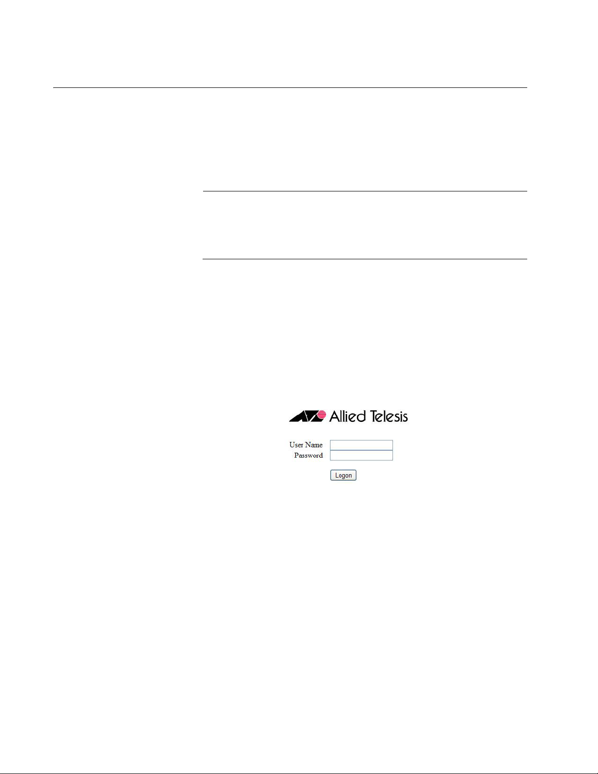
You should now see the logon window, shown in Figure 1.
Figure 1. Log On Window
3. Enter the username and password for the unit. The default values are
“manager” for the username and “friend” for the password. The
username and password are case-sensitive.
4. Click the Logon button.
18
Page 19

AT-TQ2450 Wireless Access Point User’s Guide
Note
Starting the Initial Management Session on the Access Point
If you just installed the device and are powering it on for the first time, it
queries the subnet on the LAN port for a DHCP server. If a DHCP server
responds to its query, the unit uses the IP address the server assigns to it.
If there is no DHCP server, the access point uses the default IP address
192.168.1.230.
There are a several ways to start the initial management session on the
access point. One way is to establish a direct connection between your
computer and the unit by connecting an Ethernet cable to the Ethernet port
on the computer and the LAN port on the access point. This procedure
requires changing the IP address on your computer to make it a member
of the same subnet as the default IP address on the access point. You
might perform this procedure if your network does not have a DHCP
server and you want to configure the access point before connecting it to
your network.
The initial management session may also be performed while the device is
connected to your network. However, If your network does not have a
DHCP server, you still have to change the IP address of your computer to
match the subnet of the default address of the access point. Furthermore,
if your network is divided into virtual LANs (VLANs), you have to be sure to
connect the access port and your computer to ports on an Ethernet switch
that are members of the same VLAN.
If your network has a DHCP server, use the IP address the server assigns
it to it to start the management session.
The instructions for starting the initial management session are found in
the following sections:
“Starting the Initial Management Session with a Direct Connection” on
page 20
“Starting the Initial Management Session without a DHCP Server” on
page 20
“Starting the Initial Management Session with a DHCP Server” on
page 21
The initial management session of the access point has to be
conducted through the LAN port because the default setting for the
radios is off.
19
Page 20

Chapter 1: Overview
Note
Starting the
Initial
Management
Session with a
Direct
Connection
To start the management session with a direct Ethernet connection
between your computer and the access port, perform the following
procedure:
If the access point is using PoE, you may not perform this procedure
because it involves a direct connection between your computer and
the LAN port on the access point. You may either temporarily attach
the power supply to the unit until after you have completed the initial
management session or you may instead perform one of the other
procedures for starting the initial management session.
1. Connect one end of a network cable to the LAN port on the access
point and the other end to the Ethernet network port on your computer.
(This requires removing the LAN cable you connected earlier in the
hardware installation instructions.)
2. Change the IP address on your computer to 192.168.1.n, where n is a
number from 1 to 254, but not 230. Refer to the documentation that
accompanies your computer for instructions on how to set the IP
address.
Starting the
Initial
Management
Session without a
DHCP Server
3. Set the subnet mask on your computer to 255.255.255.0.
4. Power on the access point.
5. Start the web browser on your computer.
6. Enter the IP address 192.168.1.230 in the URL field of the browser
and press the Return key.
You should now see the logon window, shown in Figure 1 on page 18.
7. Enter “manager” for the username and “friend” for the password. The
username and password are case-sensitive.
8. Click the Logon button.
This procedure explains how to start the initial management session on
the access port when the LAN port is connected to an Ethernet switch on a
network that does not have a DHCP server. To start the management
session, perform the following procedure:
1. If your network has VLANs, check to be sure that your computer and
the access port are connected to ports on the Ethernet switch that are
members of the same VLAN. This might require accessing the
management software on the switch and listing the VLANS and their
port assignments. For example, if the access port is connected to a
port that is a member of the Sales VLAN, your computer must be
20
Page 21

AT-TQ2450 Wireless Access Point User’s Guide
connected to a port that is also a member of that VLAN. If your network
is small and does not have VLANs or routers, you may connect your
computer to any port on the Ethernet switch.
2. Change the IP address on your computer to 192.168.1.n, where n is a
number from 1 to 254, but not 230. Refer to the documentation that
accompanies your computer for instructions on how to set the IP
address.
3. Set the subnet mask on your computer to 255.255.255.0.
4. Power on the access point.
5. Start the web browser on your computer.
6. Enter the IP address 192.168.1.230 in the URL field of the browser and
press the Return key.
You should now see the logon window, shown in Figure 1 on page 18.
7. Enter “manager” for the username and “friend” for the password. The
username and password are case-sensitive.
Starting the
Initial
Management
Session with a
DHCP Server
8. Click the Logon button.
This procedure explains how to start the initial management session on
the access port when the LAN port is connected to a network that has a
DHCP server. This procedure assumes that you have already configured
the DHCP server with the appropriate information for the access point
(e.g., IP address and default gateway). To start the management session,
perform the following procedure:
1. Power on the access point.
2. Start the web browser on your computer.
3. Enter the IP address of the access point in the URL field of the browser
and press the Return key. This is the IP address assigned to the
access point by the DHCP server. If you do not know the address,
refer to the DHCP server.
You should now see the logon window, shown in Figure 1 on page 18.
4. Enter “manager” for the username and “friend” for the password. The
username and password are case-sensitive.
5. Click the Logon button.
21
Page 22

Chapter 1: Overview
Using the Management Menus and Windows
Here is general information about the management menus and windows.
Web Browser
Menus
You may control the appearance of the menus with the Navigator pulldown menu in the upper right corner of the web browser windows. The
menu options are Horizontal Tabs, Vertical Tabs, and Dropdown Menus.
The Horizontal Tabs selection displays the main menu in a row near the
top of the windows. Clicking a menu selection displays the menu options
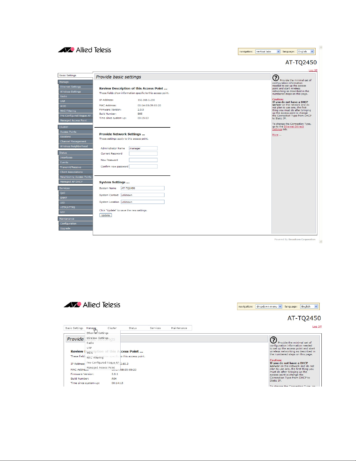
in a row beneath the main menu. Figure 2 shows the Manage menu.
Figure 2. Horizontal Menus
The Vertical Tabs selection displays the menus in a column on the left
side of the management windows, as shown in Figure 3 on page 23.
22
Page 23
AT-TQ2450 Wireless Access Point User’s Guide
Figure 3. Vertical Menus
The Dropdown Menu option displays the main menu in a horizontal row
near the top of the window. Menu options are displayed vertically when
you move the mouse over the main menu. Figure 4 shows the Manage
menu.
Figure 4. Dropdown Menus
23
Page 24

Chapter 1: Overview
The menus contain the same selections and perform the same functions
regardless of the format. You may switch between formats without
interrupting your current session or having to stop and start it again.
Saving Your
Changes
You need to remember to click the Update button when you are finished
configuring the parameters in a management window. The button is
located in the bottom of the windows. When you click the button, the
access point immediately activates your changes and saves them in the
configuration file. If you navigate to a different window without clicking the
Update button, your changes are lost and have to be reentered.
Logging Off You should always log off when you are finished managing the unit. To log
off, click the Log Off option in the upper right corners of the management
windows.
24
Page 25

Chapter 2
Basic Settings Menu
This chapter describes the management functions of the menu selections
in the Basic Settings menu. The chapter contains the following sections:
“Displaying Basic Information” on page 26
“Changing the Manager’s Login Name and Password” on page 28
“Changing the System Name, Contact, and Location” on page 29
25
Page 26
Chapter 2: Basic Settings Menu
Displaying Basic Information
This section explains how to display the following information about the
access point:
IP address
MAC address
Firmware version number
Build number
Operational time
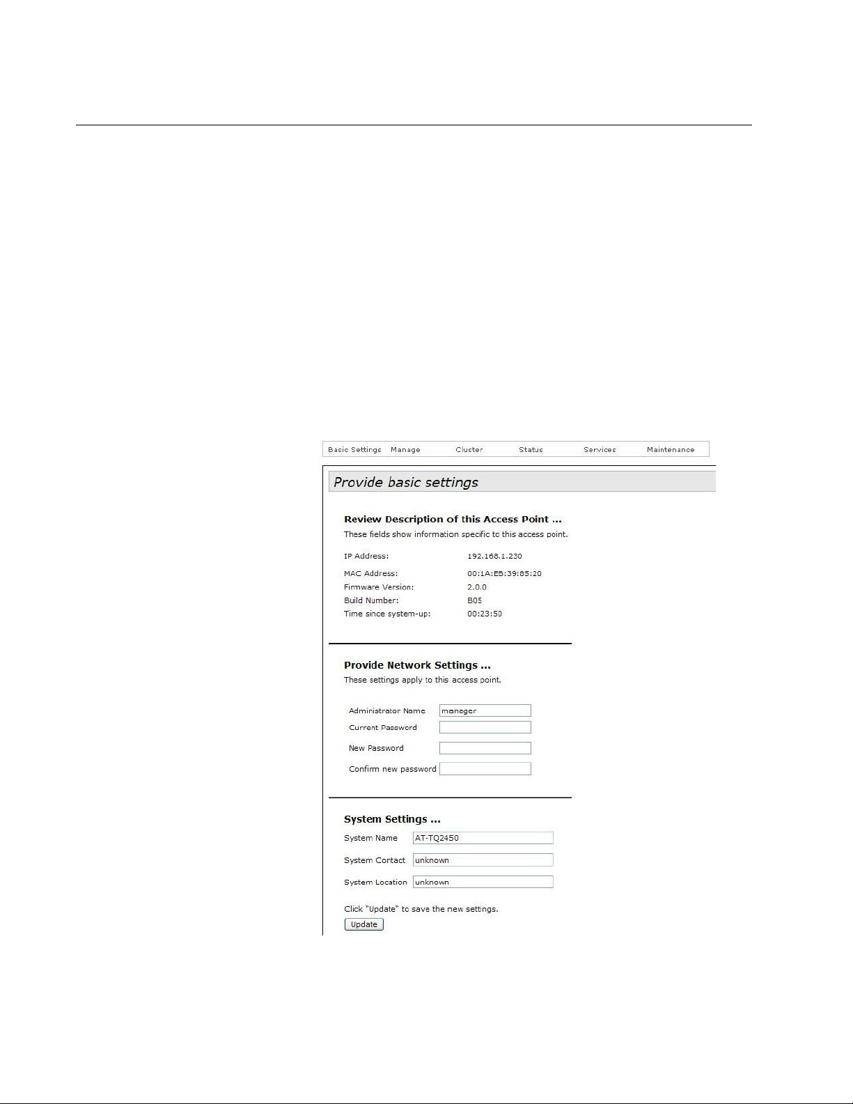
To display the information, select Basic Settings from the main menus to
display the “Provide basic settings” window. The information is contained
in the Review Description of the Access Point section of the window. Refer
to Figure 5. The fields are defined in Table 1 on page 27.
26
Figure 5. Provide Basic Settings Window
Page 27

AT-TQ2450 Wireless Access Point User’s Guide
Table 1. Review Description of this Access Point
Field Description
IP Address Displays the IP address of the access
point. For instructions on how to set the IP
address, refer to “Assigning a Static IP
Address to the Access Point” on page 32
or “Assigning a Dynamic IP Address from
a DHCP Server to the Access Point” on
page 34.
MAC Address Displays is the MAC address of the device
and radio 1. Radio 2 has a different MAC
address. You may not change the MAC
addresses of the device or radios.
Firmware Version Displays is the version number of the
management software on the access
point.
Build Number Displays the build number. This number
and the firmware version number identify
the management software.
Time since system-up Displays the amount of time since the unit
was reset or powered on.
27
Page 28

Chapter 2: Basic Settings Menu
Changing the Manager’s Login Name and Password
This procedure explains how to change the login name and password of
the manager account on the access point. The default values are
“manager” and “friend”, respectively. The access point can have only one
manager account.
Changing the name and password does not affect your current
management session of the access point.
To change the login name and password for the manager account,
perform the following procedure:
1. Select Basic Settings from the main menus.
The access point displays the “Provide basic settings” window, shown
in Figure 5 on page 26.
2. To change the manager name, select the Administrator Name field in
the Provide Network Settings section of the window and enter the new
name. Refer to Figure 5 on page 26. The name can be up to 12
alphanumeric characters. The first character must be a letter. It cannot
be a number or special character. The name is case-sensitive.
3. To change the password, perform these steps:
a. Select the Current Password field in the Provide Network Settings
section of the window and enter the account’s current password.
b. Select the New Password field and enter a new password of up to
32 alphanumeric characters. It may not contain spaces or any of
these special characters: “, $, :, <, >, ’, &, *. The password is casesensitive. The new password is displayed as a series of asterisks
on your screen.
c. Select the Confirm New Password field and enter the new
password again.
4. After editing the fields, click the Update button at the bottom of the
window to activate your changes and save them in the configuration
file on the access point. You must use the new manager name and
password for all future management sessions on the unit.
28
Page 29

AT-TQ2450 Wireless Access Point User’s Guide
Changing the System Name, Contact, and Location
This procedure explains how to identify the access point by defining the
system name, the person responsible for managing the device, and its
location. This information is optional.
To change the system name, contact, and location information, perform
the following procedure:
1. Select Basic Settings from the main menus.
The access point displays the “Provide basic settings” window. Refer
to Figure 5 on page 26.
2. To change the system name, select the System Name field in the
System Settings section of the window and enter a new name. The
name can be up to 64 alphanumeric characters. Spaces are allowed.
The default name is “AT-TQ2450.”
3. To enter the name of the person responsible for managing the unit,
select the System Contact field and enter a name. You might also
include the phone number and email address of the individual in this
field. The name can be up to 64 alphanumeric characters. Spaces are
allowed. The default name is “unknown.”
4. To specify the location of the access point, select the System Location
field and enter the location. The location can be up to 64 alphanumeric
characters. Spaces are allowed. The default location is “unknown.”
5. After editing the fields, click the Update button at the bottom of the
window to activate your changes and save them in the configuration
file on the device.
29
Page 30

Chapter 2: Basic Settings Menu
30
Page 31

Chapter 3
Manage Menu
This chapter describes the management functions of the menu selections
in the Manage menu. The chapter contains the following sections:
“Assigning a Static IP Address to the Access Point” on page 32
“Assigning a Dynamic IP Address from a DHCP Server to the Access
Point” on page 34
“Setting VLAN IDs” on page 35
“Enabling or Disabling Broadcast Ping Replies” on page 36
“Setting the Country Setting” on page 37
“Configuring Basic Radio Settings” on page 39
“Configuring the Radio Settings” on page 42
“Configuring Virtual Access Points” on page 54
“Managing Wireless Distribution System Bridges” on page 67
“Configuring the MAC Address Filter” on page 77
“Generating Event Messages for Unknown Access Points” on page 80
“Configuring the Access Point for the Optional AT-UWC Program” on
page 83
31
Page 32

Chapter 3: Manage Menu
Note
Assigning a Static IP Address to the Access Point
This section explains how to manually assign an IP address to the access
point. The unit uses the address to communicate with devices on your
network, such as management workstations, syslog servers, and RADIUS
servers. The access point may have only one IP address.
If you have a DHCP server on your network and prefer the access point
obtain its IP configuration from the server, refer to “Assigning a Dynamic
IP Address from a DHCP Server to the Access Point” on page 34.
Changing the IP address of the access point interrupts your
management session. To resume managing the device, you may
have to change the IP address of your management workstation.
To manually assign an IP address to the unit, perform the following
procedure:
1. From the Manage menu, select Ethernet Settings.
The access point displays the “Modify Ethernet (Wired) Settings”
window in Figure 6.
Figure 6. Modify Ethernet (Wired) Settings Window
2. From the Connection Type pull-down menu, select Static IP.
32
Page 33

AT-TQ2450 Wireless Access Point User’s Guide
The Static IP Address, Subnet Mask, and Default Gateway fields in the
window are activated so that you can change their values.
3. Select the Static IP Address field and enter the new IP address for the
access point. The default address is 192.168.1.230.
4. Select the Subnet Mask fields and enter the subnet mask for the IP
address. The default subnet mask is 255.255.255.0.
5. Select the Default Gateway fields and enter the default gateway
address for the unit. The default gateway address is 192.168.1.254.
The default gateway is an IP address of an interface on a router or
other Layer 3 routing device. It specifies the first hop to reaching the
subnets or networks where your management devices, such as
management workstations and syslog servers, reside. The access
point can have only one default gateway and the network portion of the
address must be the same as the IP address entered in step 3.
You have to assign a default gateway to the access point. If your
network does not have a default gateway or you do not want to assign
one to the access point at this time, enter an unused IP address of the
same network as the IP address entered in step 3.
6. If you want to specify the IP addresses of Domain Name servers, enter
up to two IP addresses in the DNS Nameservers fields. If you have
only one DNS IP address, you must enter it in the top field.
7. Click the Update button at the bottom of the window to activate and
save your changes on the access point.
Your management session is interrupted.
8. Start a new management session using the new IP address of the
device.
33
Page 34

Chapter 3: Manage Menu
Note
Assigning a Dynamic IP Address from a DHCP Server to the Access Point
This section explains how to assign an IP address to the access point from
a DHCP server. The unit uses the address to communicate with devices
on your network, such as management workstations, syslog servers, and
RADIUS servers. The access point may have only one IP address.
If you network does not have a DHCP server or you prefer to manually
assign it an IP address, refer to “Assigning a Static IP Address to the
Access Point” on page 32.
Changing the IP address of the access point interrupts your
management session. To resume managing the device, you may
have to change the IP address of your management workstation.
To activate the DHCP client to have the access point obtain its IP address
configuration from a DHCP server, perform the following procedure:
1. From the Manage menu, select Ethernet Settings.
The access point displays the “Modify Ethernet (Wired) settings”
window in Figure 6 on page 32.
2. From the Connection Type menu, select DHCP. This is the default
setting.
3. If you want to manually specify the IP addresses of Domain Name
servers, click Manual dialog button for DNS Nameservers and enter up
to two IP addresses. If you have only one DNS IP address, you must
enter it in the top address field.
If you want the access point to use the DNS addresses provided by the
DHCP server, click the Dynamic dialog circle.
4. Click the Update button at the bottom of the window to activate and
save your changes on the access point.
Your management session is interrupted.
The DHCP client on the unit queries the subnet on the LAN port for a
DHCP server. If it receives a response, it uses the IP configuration the
server provides. If there is no response, the unit uses the default IP
address 192.168.1.230.
5. To resume your management session on the device, enter the new IP
address of the access point in the URL field of your web browser.
34
Page 35

Setting VLAN IDs
AT-TQ2450 Wireless Access Point User’s Guide
The “Modify Ethernet (Wired) settings” window has two settings for VLAN
IDs (VIDs). One setting is used to specify the management VLAN and the
other is used to designate a VLAN for untagged traffic.
Management
VLAN ID
VLAN ID for
Untagged Traffic
The Management VLAN ID field in the “Modify Ethernet (Wired) settings”
window is used to specify the VLAN of your management workstations. To
specify the management VID, perform the following procedure:
1. From the Manage menu, select Ethernet Settings.
The access point displays the “Modify Ethernet (Wired) settings”
window in Figure 6 on page 32.
2. Select the Management VLAN ID field and enter a value of 1 to 4094.
The number should be the VID of the VLAN where your management
workstation is located. You may specify only one VID.
3. Click the Update button to activate and save your changes on the
access point.
The Untagged VLAN and Untagged VLAN ID fields in the “Modify Ethernet
(Wired) settings” window allow you to specify a VLAN for untagged traffic.
To specify the VLAN, perform the following procedure:
1. From the Manage menu, select Ethernet Settings.
The access point displays the “Modify Ethernet (Wired) settings”
window in Figure 6 on page 32.
2. For the Untagged VLAN field, do one of the following:
Click Enabled if you want to be able to designate one VLAN on the
access point as an untagged VLAN. This is the default setting.
Click Disabled if the access point is to handle only tagged packets.
3. If your selected Enabled, select the Untagged VLAN ID field and enter
the ID number of the VLAN which is to carry untagged packets. You
may enter only one VID. The default value is 1.
4. Click the Update button to activate and save your changes on the
access point.
35
Page 36

Chapter 3: Manage Menu
Enabling or Disabling Broadcast Ping Replies
You may configure the access point to either ignore or reply to ICMP echo
requests to IP broadcast addresses, also referred to as broadcast pings.
To configure broadcast ping replies, perform the following procedure:
1. From the Manage menu, select Ethernet Settings.
The access point displays the “Modify Ethernet (Wired) settings”
window in Figure 6 on page 32.
2. In the Directed Broadcast ICMP Reply field, do one of the following:
If you want the access point to respond to broadcast pings, click
the Enabled dialog circle.
If you do not want the access point to respond to broadcast pings,
click the Disabled dialog circle.
3. Click the Update button to activate and save your changes on the
access point.
36
Page 37

Setting the Country Setting
Note
You should set the country setting of the access point as soon as you
install the unit. This ensures that the device operates in compliance with
the codes and regulations of your region or country.
Changing the country setting of the access point disables both
radios. Consequently, this procedure is disruptive to the operations
of your network if the unit is actively forwarding network traffic.
To set the country setting, perform the following procedure:
1. Select Wireless Settings from the Manage menu.
The access point displays the “Modify wireless settings” window,
shown in Figure 7.
AT-TQ2450 Wireless Access Point User’s Guide
Figure 7. Modify Wireless Settings Window
2. Select the Country pull-down menu and select your country or region.
37
Page 38

Chapter 3: Manage Menu
Note
If the Country pull-down menu is deactivated, the country parameter
was set by the manufacturer and cannot be changed. Contact your
Allied Telesis sales representative for assistance if the setting is not
correct for your country or region.
The access point displays a confirmation prompt.
3. Click OK to change the country setting or Cancel to cancel the
procedure.
If you click OK, the access point changes the country setting and
disables both radios on the access point. For instructions on how to
enable the radios and configure their settings, refer to “Configuring
Basic Radio Settings” on page 39 and “Configuring the Radio Settings”
on page 42.
This procedure does not require clicking the Update button.
You must now reboot the access point. The new country setting is not
active until the unit is rebooted. To reboot the unit, either power off and
on the unit or continue with these steps:
4. From the Maintenance menu, select Configuration.
5. Click the Reboot button in the To Reboot the Access Point section of
the “Manage the Access Point’s Configuration” window.
6. When the access point displays a confirmation prompt, click OK to
reboot the unit or Cancel to cancel the procedure.
7. To resume managing the unit, wait for it to complete initializing its
management software and then start a new management session.
38
Page 39

Configuring Basic Radio Settings
The management software has two windows for configuring the
operational settings of the radios in the access point. The “Modify radios
settings” window, described in “Configuring the Radio Settings” on
page 42, is the main window for adjusting the radio parameters because it
contains all the parameters, everything from operational mode to
broadcast/multicast rate limiting. This is the window to use when you need
to fine tune the properties of the radios.
If you are only interested in configuring basic radio parameters, you may
find everything you need in the “Modify wireless settings” window, which is
the topic of this section. From this window you can perform these basic
radio functions:
Enable or disable a radio
Select the operational mode
Select the channel
AT-TQ2450 Wireless Access Point User’s Guide
Enable or disable the station isolation mode
When you change a radio parameter in the “Modify wireless settings”
window, the change is reflected in the “Modify radios settings” window. So
you could enable a radio here and perhaps select the channel, and then
move to the “Modify radio settings” window to adjust additional
parameters.
The “Modify wireless settings” window does contain one parameter,
however, that is not in the “Modify radio settings” window, and that is the
station isolation mode parameter. The parameter determines whether the
clients of a VAP can communicate with each other through the access
point. That parameter can only be set from this window.
To configure basic radio settings from the “Modify wireless settings”
window, perform the following procedure:
1. From the Manage menu, select Wireless Settings.
The access point displays the “Modify wireless settings” window. An
example is shown in Figure 7 on page 37.
2. Configure the settings as needed. The parameters are described in
Table 2 on page 40.
3. When you are finished configuring the parameters, click the Update
button to activate and save your changes on the access point.
39
Page 40

Chapter 3: Manage Menu
Table 2. Modify Wireless Settings Window
Field Description
Radio On Off Enables or disables the radio. The
selections are described here:
- On: Enables the radio. You have to
enable a radio before you can configure
its parameter settings.
- Off: Disables the radio. This is the
default setting.
MAC Address Displays the MAC address of the radio.
This value cannot be changed
Mode Specifies the Physical Layer (PHY)
standard of the radio. The available
modes depend on the radio and country.
The modes are:
- IEEE 802.11a: The access point accepts
only 802.11a clients.
- IEEE 802.11b/g: The access point
accepts only 802.11b and 802.11g clients.
- IEEE 802.11a/n: The access point
accepts only 802.11a and 802.11n clients
operating at 5 GHz. This is the default
setting for the 5 GHz radio.
- IEEE 802.11b/g/n: The access point
accepts 802.11b, 802.11g, and 802.11n
clients operating at 2.4 GHz. This is the
default setting for the 2.4 GHz radio.
- 2.4 GHz IEEE 802.11n: The access
point accepts only 802.11n clients
operating at 2.4 GHz.
- 5 GHz IEEE 802.11n: The access point
accepts only 802.11n clients operating at
5 GHz.
40
Page 41

AT-TQ2450 Wireless Access Point User’s Guide
Table 2. Modify Wireless Settings Window (Continued)
Field Description
Channel Specifies the channel for the radio in the
access point. The number of available
channels varies by radio, mode, and
country. Here are the guidelines:
- At the Auto setting, the access point sets
the channel automatically. The access
point listens on the channels and selects
the one with the least traffic.This is the
default setting.
- You can select a channel from the pulldown menu. You may select only one
channel.
- The Auto selection is not available if you
use the cluster feature to automatically
assign the channels to the radios in the
access points. For information, refer to
“Using Automatic Channel Assignments”
on page 103.
Station Isolation Enables or disables station isolation.
When station isolation is enabled, the
access point does not allow the wireless
clients of a VAP to communicate with
each other, but does allow them to
communicate with clients in other VAPs
and with the wired LAN.
The feature is disabled when the dialog
box is empty and enabled when the dialog
box has a check mark. The default setting
is disabled.
To activate or deactivate the feature, click
the dialog box to insert or remove the
check mark.
41
Page 42

Chapter 3: Manage Menu
Configuring the Radio Settings
To configure the parameter settings of the 2.4 and 5 GHz radios, perform
the following procedure:
1. From the Manage menu, select Radio.
The management software displays the “Modify radio settings
window,” shown in Figure 8 on page 43.
2. From the Radio pull-down menu, select a radio. Options 1 and 2 are
the 2.4 and 5 GHz radios, respectively. The default is radio 1. You can
configure only one radio at a time.
3. To activate a radio, click the On dialog circle for the Status option. You
cannot configure a radio when its status is off. To deactivate a radio,
click the Off dialog circle.
4. Configure the radio parameters, which are defined in Table 3 on
page 44.
5. When you are finished configuring the parameters, click the Update
button to activate and save your changes on the access point.
42
Page 43

AT-TQ2450 Wireless Access Point User’s Guide
Figure 8. Modify Radio Settings Window
43
Page 44

Chapter 3: Manage Menu
Table 3. Modify Radio Settings Window
Parameter Description
Mode Specifies the Physical Layer (PHY)
standard of the radio. The available
modes depend on the radio and country.
The modes are:
- IEEE 802.11a: The access point accepts
only 802.11a clients.
- IEEE 802.11b/g: The access point
accepts only 802.11b and 802.11g clients.
- IEEE 802.11a/n: The access point
accepts only 802.11a and 802.11n clients
operating at 5 GHz. This is the default
setting for the 5 GHz radio.
- IEEE 802.11b/g/n: The access point
accepts 802.11b, 802.11g, and 802.11n
clients operating at 2.4 GHz. This is the
default setting for the 2.4 GHz radio.
- 2.4 GHz IEEE 802.11n: The access
point accepts only 802.11n clients
operating at 2.4 GHz.
- 5 GHz IEEE 802.11n: The access point
accepts only 802.11n clients operating at
5 GHz.
44
Page 45

AT-TQ2450 Wireless Access Point User’s Guide
Table 3. Modify Radio Settings Window (Continued)
Parameter Description
Channel Specifies the radio channel. The available
channels vary by radio, mode, and
country. Here are the guidelines:
- The Auto setting, the default setting, sets
the channel automatically. The access
point selects the channel with the least
traffic. This is the default setting.
- You can set the channel manually using
the Channel pull-down menu.
- The Auto selection is not available when
automatic channel reassignment in the
cluster feature is activated, as explained
in Chapter 4, “Cluster Menu” on page 87.
- If you select Auto, you may use the
Eligible Channels parameter to restrict the
channels from which the access point
may choose.
- You must set the channel manually if you
are using the Wireless Distribution
System (WDS) bridge feature, as
explained in “Managing Wireless
Distribution System Bridges” on page 67.
Eligible Channels Specifies the available channels when the
channel is selected automatically. This
selection is unavailable when the channel
is selected manually. The available
channels vary by radio, mode, and
country. To deselect a channel, click its
dialog box to remove the check mark. The
default is all available channels.
45
Page 46

Chapter 3: Manage Menu
Table 3. Modify Radio Settings Window (Continued)
Parameter Description
Periodical Channel
Refresh
Specifies whether the access point
periodically reruns the channel selection
process. Here are the guidelines:
- This selection is only available when the
Channel parameter is set to Auto.
- Adding a check mark to the dialog box
enables the feature.
- Removing the check mark from the
dialog box disables the feature. This is the
default setting.
- The access point runs the channel
selection process every 24 hours, but only
if the radio is not forwarding traffic from
wireless clients. If it detects traffic, the
access point delays the selection process
for thirty minutes.
Channel Bandwidth Specifies whether the radio should use a
40 MHz-wide channel or the legacy 20
MHz-wide channel. Here are the
guidelines:
46
- The 40 MHz-wide channel allows for
higher data rates, but reduces the number
of available channels for other wireless
devices.
- This parameter is only available with
802.11n modes.
Page 47

AT-TQ2450 Wireless Access Point User’s Guide
Table 3. Modify Radio Settings Window (Continued)
Parameter Description
Primary Channel Specifies the location of the Primary
channel when a radio is operating at 40
MHz.
A 40 MHz channel consists of two 20 MHz
channels. They are contiguous in the
frequency domain and referred to as the
Primary and Secondary channels. The
Primary channel is used by 802.11n
clients that support only a 20 MHz
channel bandwidth, and for legacy clients.
You may use this parameter to specify the
Primary channel of the 40 MHz
bandwidth. The options are described
here:
- Upper: Designates the upper 20 MHz
channel of the 40 MHz bandwidth as the
Primary channel.
- Lower: Designates the lower 20 MHz
channel of the 40 MHz bandwidth as the
Primary channel. This is the default
setting.
This parameter is only available with
802.11n modes.
47
Page 48

Chapter 3: Manage Menu
Table 3. Modify Radio Settings Window (Continued)
Parameter Description
Short Guard Interval
Supported
Specifies the dead time interval, in
nanoseconds, between OFDM symbols.
The guard interval prevents Inter-Symbol
and Inter-Carrier Interference (ISI, ICI).
The 802.11n mode supports a reduction in
the interval from 800 nanoseconds,
defined in the a and g standards, to 400
nanoseconds. This may provide up to a
10% improvement in data throughput. The
selections are described here:
- Yes: The access point uses a 400 ns
guard interval when communicating with
clients that also support the feature. This
is the default setting.
- No: The access point uses an 800 ns
guard interval.
This parameter is only available with the
802.11n modes.
48
Page 49

AT-TQ2450 Wireless Access Point User’s Guide
Table 3. Modify Radio Settings Window (Continued)
Parameter Description
Multidomain Regulatory
Mode
Specifies whether a radio should operate
in the Multidomain Regulatory Mode
(World Mode) and include the country
code in its beacons and probe responses.
This allows client stations to operate in
any country without reconfiguration.
This feature only applies to radio 1
because it operates in the g band (2.4
GHz band). This selection does not apply
to radio 2 because it operates in the a
band (5 GHz band) and always includes
the country code in its beacons, as
specified in the 802.11h standard.
The settings are described here:
- Enabled: Activates the Multidomain
Regulatory Mode (World Mode) and
includes the country code in the beacons
and probe responses.
- Disabled: Disables the Multidomain
Regulatory Mode (World Mode) and
prevents the transmission of the country
code in beacons and probe responses.
49
Page 50

Chapter 3: Manage Menu
Table 3. Modify Radio Settings Window (Continued)
Parameter Description
Protection Enables or disables rules that guarantee
that transmissions do not cause
interference with legacy stations or
applications. The possible settings are
describe here:
- Auto: This setting enables protection
when legacy devices are within range of
the radio.
- Off: This setting disables the protections.
Legacy clients and access points within
range may be affected by 802.11n
transmissions.
Here are the guidelines:
- The protection applies to 802.11n and
802.11b/g.
- Activating protection does not prevent
clients from associating with the access
point.
Beacon Interval Specifies the time interval, in milliseconds,
for transmissions of beacon frames. The
access point transmits beacon frames to
announce the existence of the wireless
network. The range is 20 to 2000
milliseconds. The default setting is 100
milliseconds (10 beacon frames per
second).
DTIM Period Specifies the Delivery Traffic Information
Map (DTIM) period. This value specifies
how often clients sleeping in low power
mode should check the access point for
buffered traffic. The interval is defined in
beacon frames. The range is 1 to 255
beacons frames. The default is 2 beacon
frames.
50
Page 51

AT-TQ2450 Wireless Access Point User’s Guide
Table 3. Modify Radio Settings Window (Continued)
Parameter Description
Fragmentation Threshold Specifies packet size for fragmentation.
The fragmentation threshold lets you
control the maximum size of packets the
access point transmits. Packets that
exceed the threshold are transmitted as
multiple 802.11 packets.
The range is 256 to 2346 bytes. Setting
the threshold to the maximum value
effectively disables fragmentation.
Fragmentation involves more overhead
because of the extra work in dividing up
and reassembling frames, which can
reduce throughput. But fragmentation can
be useful in controlling interference.
RTS Threshold Specifies the size in octets of MPDUs that
initiate a Request to Send (RTS) and
Clear to Send (CTS) handshake. The
range is 0 to 2347 octets.
You may use this parameter to control the
use of RTS/CTS handshakes when the
access point transmits MPDUs. The
access point uses the handshake before
transmitting MPDUs that exceed the
defined threshold. If you specify a low
value, RTS packets are sent more
frequently. This may consume more
bandwidth and reduce the throughput. But
more RST packets may help a network
recover from interference or collisions,
which might occur on a busy network.
Maximum Stations Specifies the maximum number of clients
the access point supports. The value is 0
to 200. When this parameter is set to 0,
the access point rejects all clients. Allied
Telesis recommends setting this
parameter to 30 clients. The default is 200
clients.
51
Page 52

Chapter 3: Manage Menu
Table 3. Modify Radio Settings Window (Continued)
Parameter Description
Transmit Power Specifies the transmission power of the
access point. The power is selected from
a list of percentages, in the range of 1% to
100%. The default is 100%. Here are the
guidelines:
- High transmission power levels are more
cost-effective than low settings because
the access point has a greater range. This
reduces the number of access points
required to cover a particular area.
- Low transmission power settings can be
useful in reducing overlap and
interference between access points or
increasing security by limiting the wireless
signals to a physical location.
Fixed Multicast Rate Specifies the multicast transmission rate
of the access point. At the default Auto
setting, the multicast transmission rate is
fixed to the minimum rate in the Legacy
Rate Sets setting. The value is in Mbps.
Legacy Rate Sets Specifies the supported and advertised
data transmission rates of the access
point. Here are the guidelines:
- The Supported row specifies the data
rates the access point supports. The
default setting is all data rates.
- The Basic row specifies the data rates
the access point advertises to other
access points and wireless clients.
- The access point is generally more
efficient when it advertises a subset of its
supported data rates.
MCS (Data Rate) Settings Specifies the Modulation and Coding
Scheme (MCS) index the radio should
advertise to 802.11n clients. The MCS
indexes (also known as MCS data rates)
are defined in the 802.11n standard.
52
Page 53

AT-TQ2450 Wireless Access Point User’s Guide
Table 3. Modify Radio Settings Window (Continued)
Parameter Description
Broadcast/Multicast Rate
Limiting
Enables or disables rate limiting of
broadcast and multicast packets. Here are
the guidelines
- To activate rate limiting, click the dialog
box to add a check mark. To deactivate
rate limiting, click the box to remove the
check mark. The default setting is
disabled.
- The Rate Limit parameter defines the
maximum number of broadcast and
multicast packets per second of the
access point. The parameter has a range
of 1 to 50 packets per second. The default
is 50 packets per second.
- The Rate Limit Burst parameter allows
intermittent bursts of traffic on the access
point above the rate limit. The default is
75 packets per second.
- The Rate Limit Burst parameter must be
greater than the Rate Limit parameter.
53
Page 54

Chapter 3: Manage Menu
Note
Configuring Virtual Access Points
Virtual access points (VAPs) function as independent broadcast domains
and are the wireless equivalent of Ethernet VLANs. They are seen by
clients as independent access points, with their own VIDs, SSIDs, and
security methods.
Here are the guidelines to VAPs:
Each radio can have up to 16 VAPs. Allied Telesis recommends no
more than five VAPs per radio.
The VAPs are numbered from 0 to 15.
If you use the cluster feature, VAPs are shared among the access
points of the cluster. For further information, refer to Chapter 4,
“Cluster Menu” on page 87.
You can enable and disable the VAPs individually, except for the
default VAP, VAP0, which can only be disabled by disabling the
radio itself.
The security methods for the VAPs are 802.1x, static WEP,
Enterprise WPA, and Personal WPA.
The VAPs of a radio can have different security methods.
VAPs can have the same or different VLAN IDs.
The access point does not forward traffic on disabled VAPs.
To configure VAPs, perform the following procedure:
1. From the Manage menu, select VAP.
The management software displays the “Modify Virtual Access Point
settings” window, shown in Figure 9 on page 56.
2. Use the Radio pull-down menu above the list of VAPs to select a radio.
Menu options 1 and 2 are the 2.4 and 5 GHz radios, respectively. The
default is radio 1. You can configure only one radio at a time.
3. Click the Enabled dialog box of the VAP you want to edit. You cannot
edit a VAP when it is disabled. A VAP is enabled when the Enabled
dialog box has a check mark and disabled when the dialog box is
empty. You can configure more than one VAP at a time.
If you remove the check mark from the Enabled dialog box, you
disable the VAP. A disabled VAP does not forward network traffic.
4. Enter the VID for the VAP in the VLAN ID field.
54
Page 55

AT-TQ2450 Wireless Access Point User’s Guide
Here are the guidelines for VIDs:
The range is 1 to 4094.
The default is VID 1.
You may assign the same VID to more than one VAP.
A VAP can have only one VID.
The number is ignored for wireless clients who are assigned VIDs
from a RADIUS server because VIDs from a RADIUS server take
precedence over the number in this field. Consequently, if you
configure the security on a VAP to 802.1X or WPA Enterprise, both
of which require a RADIUS server, the value in this field is ignored
for clients who have VIDs in their RADIUS accounts.
If you use 802.1x security for a VAP and activate Require VLAN ID
in Dynamic VLAN, the VID for the dynamic VLAN must come from
the client accounts on the RADIUS server.
5. Select the SSID field and enter a name for the VAP. Here are the
guidelines:
A VAP must have a name.
A name can be from 1 to 32 characters.
Spaces are allowed.
You may assign the same name to more than one VAP.
6. Click the Broadcast SSID dialog box to either enable or disable the
broadcast of the SSID of the VAP by the radio on the access point.
When the dialog box has a check mark, the default setting, the access
point transmits the SSID to advertise the VAP to the clients. When the
dialog box is empty, the access point does not advertise the VAP.
Clients who want to connect to a VAP that is not advertised have to
know its name.
7. From the Security pull-down menu, select the security method for the
VAP and configure the security settings. The security options are
described in the following sections:
“No Security” on page 57
“IEEE 802.1x Security” on page 57
“Static WEP” on page 59
“WPA Enterprise” on page 62
“WPA Personal” on page 65
The default security level for VAPs is None, which does not provide
authentication or packet encryption for VAPs.
55
Page 56

Chapter 3: Manage Menu
8. If you want to control access to your network through the VAP by
filtering clients by their MAC addresses, select the MAC Filtering pulldown menu and select Enabled. To disable MAC address filtering,
select Disabled, the default setting. For instructions on how to
configure the filter, refer to “Configuring the MAC Address Filter” on
page 77.
9. Click the Update button to activate and save your changes on the
access point.
The “+” button to the right of each VAP row displays the security
settings.
56
Figure 9. Modify Virtual Access Point Settings Window
Page 57

AT-TQ2450 Wireless Access Point User’s Guide
No Security The None security level is intended for VAPs with wireless clients that do
not require encryption or authentication. This is the default setting.
IEEE 802.1x
Security
The guidelines for IEEE 802.1x security are listed here:
This security method requires an external RADIUS server capable
of EAP.
The authentication server must have Protected EAP (PEAP) and
MSCHAP V2 to support Windows clients.
The clients and VAPs must use the same authentication method.
The IEEE 802.1x security parameters are shown in Figure 10 and
described in Table 4.
Figure 10. 802.1x Authentication for VAPs
Table 4. IEEE 802.1x
Field Description
RADIUS IP Address Enter the IPv4 address of the primary
RADIUS server.
Secondary RADIUS IP
Address
Enter the IPv4 address of the secondary
RADIUS server. This field is optional. The
access point sends authentication
requests to this address if the primary
RADIUS server does not respond to
requests.
57
Page 58

Chapter 3: Manage Menu
Table 4. IEEE 802.1x (Continued)
Field Description
RADIUS Key Enter the shared secret key for the
primary RADIUS server. The key can be
up to 128 characters and can consist of
letters, numbers, and special characters.
The key is case-sensitive. This key must
be the same as the key on the server.
Secondary RADIUS Key Enter the shared secret key for the
secondary RADIUS server.
RADIUS Port (Range: 0 -
65535)
RADIUS Accounting Port
(Range: 0 - 65535)
Enable RADIUS
Accounting
Require VLAN ID in
Dynamic VLAN
Enter the RADIUS port number of the
RADIUS server. If you entered IP
addresses for both primary and
secondary servers, the units must use the
same port number. The default is 1812.
Enter the RADIUS accounting port
number of the RADIUS server. If you
entered IP addresses for both primary and
secondary servers, the units must use the
same accounting port number. The
default is 1813.
Enable or disable RADIUS accounting by
clicking the dialog box. The feature is
enable when the dialog box has a check
mark and disabled when the dialog box is
empty. The default setting for accounting
is disabled.
Enable or disable whether wireless clients
receive their VIDs from their accounts on
the RADIUS server. When the dialog box
has a check mark, the feature is enabled
and the wireless clients receive their VIDs
from the RADIUS server when they are
authenticated. The feature is disabled
when the dialog box is empty. The default
setting is disabled.
58
Broadcast Key Refresh
Rate (Range: 0 - 86400)
Specify the refresh rate for the broadcast
(group) key for the clients of the VAP. The
range is 0 to 86400 seconds. The default
is 0 seconds. The value 0 disables to
refresh rate so that the broadcast key is
not refreshed.
Page 59

AT-TQ2450 Wireless Access Point User’s Guide
Table 4. IEEE 802.1x (Continued)
Field Description
Session Key Refresh Rate
(Range: 0 - 86400)
Specify the refresh rate for the session
(unicast) key for the clients of the VAP.
The range is 0 to 86400 seconds. The
default is 0 seconds. The value 0 disables
the refresh rate so that the unicast key is
not refreshed.
Static WEP The parameter settings for static WEP security are shown in Figure 11 and
defined in Table 5.
Figure 11. Static WEP Encryption for VAPs
Table 5. Static WEP
Field Description
Transfer Key Index Select the key the access point should
use to encrypt network traffic.
Key Length Select the key length of 64 or 128 bits.
The default is 128 bits.
Key Type Select whether the key is ASCII or
hexadecimal. The default is hexadecimal.
59
Page 60

Chapter 3: Manage Menu
Table 5. Static WEP (Continued)
Field Description
WEP Keys Enter up to four WEP keys in the fields
numbered 1 to 4. The key length and type
settings determine the length and format
of the keys. The order of the keys has be
the same on the access point and clients.
Here are the guidelines for ASCII keys:
An ASCII key may contain upper and
lower characters and the numbers 0 to 9.
An ASCII key is case-sensitive.
The key length of 64 bits requires five
ASCII characters.
The key length of 128 bits requires 13
ASCII characters.
Here are the guidelines for hexadecimal
keys:
A hexadecimal key may contain the letters
A to F and numbers 0 to 9.
The key length of 64 bits requires 10
hexadecimal characters.
The key length of 128 bits requires 26
hexadecimal characters.
60
Page 61

AT-TQ2450 Wireless Access Point User’s Guide
Table 5. Static WEP (Continued)
Field Description
Authentication Specify whether or not the access point
authenticates VAP clients. The options
are described here.
Open System: The access point does not
authenticate the VAP clients. All clients,
even those without the correct WEP keys,
are allowed to connect to the access
point. This is the default setting. (Clients
in an open system VAP still must have the
correct WEP key to encrypt and decrypt
the traffic they exchange with the access
point.)
Shared Key: Clients must have the correct
WEP key to connect with the access
point. Clients without the correct WEP key
may not associate with the device.
Both Open System and Shared Key:
Clients configured in WEP shared key
mode must have the correct WEP key to
connect to the access point. Clients
configured in WEP open system mode do
not need the correct WEP key to connect
to the access point.
61
Page 62

Chapter 3: Manage Menu
WPA Enterprise The WPA Enterprise security parameters are shown in Figure 12 and
defined in Table 6 on page 63.
Figure 12. WPA Enterprise for VAPs
62
Page 63

AT-TQ2450 Wireless Access Point User’s Guide
Table 6. WPA Enterprise
Field Description
WPA Versions Select the WPA version. The options are
listed here:
- WPA: Select this option if all the wireless
clients of the VAP support WPA, but not
WPA2.
- WPA2: Select this option if all the clients
support WPA2, but not WPA. This is the
default setting.
- Both WPA and WPA2 - Select both
options if the VAP has both WPA and
WPA2 clients.
- Enable-pre-authentication: Select this
option if the VAP has WPA2 clients and
you want the access point to share the
pre-authentication packets from the
clients with other access points. This can
speed up authentication for roaming
clients who connect to multiple access
points. This option does not apply to WPA
clients.
Cipher Suites Select the cipher suite for the VAP, The
options are listed here:
- TKIP
- CCMP (AES)
- Both TKIP and CCMP (AES)
When both TKIP and CCMP (AES) are
selected, clients configured to use WPA
with RADIUS must have one of the
following:
- A valid TKIP RADIUS IP address and
RADIUS key.
- A valid CCMP (AES) IP address and
RADIUS key.
RADIUS IP Address Enter the IPv4 address of the primary
RADIUS server.
63
Page 64

Chapter 3: Manage Menu
Table 6. WPA Enterprise (Continued)
Field Description
Secondary RADIUS IP
Address
Enter the IPv4 address of a secondary
RADIUS server. This field is optional. The
access point sends authentication
requests to this address if the primary
RADIUS server does not respond to
requests.
RADIUS Key Enter the shared secret key for the
primary RADIUS server. The key can be
up to 128 characters and can consist of
letters, numbers, and special characters.
The key is case-sensitive. This key must
be same on the access point and server.
Secondary RADIUS Key Enter the shared secret key for the
secondary RADIUS server.
RADIUS Port (Range: 0 -
65535)
Enter the RADIUS port number of the
RADIUS server. If you entered IP
addresses for both primary and
secondary servers, the units must be
using the same port number. The default
is 1812.
RADIUS Accounting Port
(Range: 0 - 65535)
Enable RADIUS
Accounting
Require VLAN ID in
Dynamic VLAN
Enter the RADIUS accounting port
number of the RADIUS server. If you
entered IP addresses for both primary and
secondary servers, the units must use the
same accounting port number. The
default is 1813.
Enable or disable RADIUS accounting by
clicking the dialog box. The feature is
enable when the dialog box has a check
mark and disabled when the dialog box is
empty. The default setting for accounting
is disabled.
Enable this option to require that the
wireless clients of the VAP be assigned
VLAN IDs from the RADIUS server. When
this option is enabled, the VAP does not
accept clients that are not assigned VLAN
IDs by the RADIUS severs. The option is
enabled when it has a check mark. The
default setting is disabled.
64
Page 65

AT-TQ2450 Wireless Access Point User’s Guide
Table 6. WPA Enterprise (Continued)
Field Description
Broadcast Key Refresh
Rate (Range: 0 - 86400)
Specify the refresh interval rate for the
broadcast (group) key. The range is 0 to
86400 seconds. The value 0 prevents the
key from being refreshed.
Session Key Refresh Rate
(Range: 0 - 86400)
Specify the refresh interval rate for the
session (unicast) keys. The range is 0 to
86400 seconds. The value 0 prevents the
keys from being refreshed.
WPA Personal The options for WPA Personal are shown in Figure 13 and defined in
Table 7.
Figure 13. WPA Personal for VAPs
Table 7. WPA Personal
Field Description
WPA Versions Select the WPA version. The options are
listed here:
- WPA: Select this option if the VAP
wireless clients support WPA, but not
WPA2.
- WPA2: Select this option if the clients
support WPA2, but not WPA. This is the
default setting.
- Both WPA and WPA2 - Select both
options if the VAP has both WPA and
WPA2 clients.
65
Page 66

Chapter 3: Manage Menu
Table 7. WPA Personal (Continued)
Field Description
Cipher Suites Select the cipher suite for the VAP. The
options are listed here:
- TKIP
- CCMP (AES)
- Both TKIP and CCMP (AES)
When both TKIP and CCMP (AES) are
selected, clients who are using WPA must
have one of the following:
- A valid TKIP key.
- A valid CCMP (AES) key.
Key Enter a shared secret key of 8 to 63
alphanumeric characters. The key can
include special characters.
Broadcast Key Refresh
Rate (Range: 0 - 86400)
Specify the refresh interval rate for the
broadcast (group) key. The range is 0 to
86400 seconds. The value 0 prevents the
key from being refreshed. The default is 0
seconds.
66
Page 67

Managing Wireless Distribution System Bridges
LAN Segment 1 LAN Segment 2
AB
WDS Bridge
LAN Segment
AB
WDS Bridge
A wireless distribution system (WDS) bridge is a wireless link between two
access points. The link allows the units to forward traffic directly to each
other over a wireless connection as if they were connected with a physical
Ethernet wire.
You can use WDS bridges to link network segments with wireless, rather
than wired, connections. This is illustrated in Figure 14 where access
points A and B form a WDS bridge to connect two LAN segments together.
Figure 14. WDS Bridge Used to Connect LAN Segments
AT-TQ2450 Wireless Access Point User’s Guide
Configurations of
WDS Bridges
You might also use the feature to extend a network into areas where
Ethernet cable installation would be impractical or expensive. In Figure 15,
access point B is located in an area that does not have Ethernet cabling.
Consequently, its LAN port is not connected to the wired network.
However, its wireless clients still have access to the network because of
the WDS bridge to access point A, whose LAN port is connected to the
wired network.
Figure 15. WDS Bridge Used to Extend a Network
You can connect up to four AT-TQ2450 Access Points with WDS bridges.
Figure 16 on page 68 illustrates the supported configurations.
67
Page 68

Chapter 3: Manage Menu
One configuration for a WDS bridge of two units.
One configuration for a WDS bridge of three units.
Two configurations for a WDS bridge of four units.
Figure 16. Supported Configurations of WDS Bridges
Here are the configuration restrictions for WDS bridges:
The wireless connections of the access points in a WDS bridge
community must not form a loop. For instance, Figure 17 on page
69 is an invalid loop configuration of three access points.
68
Page 69

AT-TQ2450 Wireless Access Point User’s Guide
Figure 17. Invalid Loop Configuration of Access Points
Additionally, the access points may not form loops with wired
devices. An example is shown in Figure 18.
Figure 18. Invalid Loop Configuration of Access Points to a Wired Network
Device
Radio You may use either the 2.4 or 5 GHz radios in the units to create a WDS
bridge. The access points must all use the same radio.
Radio Mode The access points must use the same radio mode. You may use any
available radio mode. The available modes depend on the country or area
where the access point is installed.
Radio Channel When access points are operating in close proximity to each other such
that there is an overlap in coverage, the usual practice is to set the radios
to different channels to minimize radio interference and improve
performance.
The radios in the access points of a WDS bridge, however, have to use the
same channel. This means that you have to disable automatic channel
selection, which is the default settings on the units, and manually select
the channel. The common channel between the access points can be any
available channel.
VAP0 The access points of a WDS bridge use VAP0 as the wireless link. The
VAP assignment cannot be changed. Wireless clients should not be
allowed to use VAP0 when the devices are arranged in a WDS bridge
because the bridge could experience a reduction in performance. Wireless
clients should use other VAPs on the units to access the network.
69
Page 70

Chapter 3: Manage Menu
Encryption Here are the available encryption settings for a WDS bridge:
No encryption
Static WEP
WPA Personal
The available encryption modes for a WDS bridge vary depending on the
radio mode and VAP security. The possible settings are listed in Table 8.
For example, if you want to use WPA Personal on a WDS bridge, you
have to set VAP0 to either WPA Personal or WPA Enterprise.
Table 8. Available Encryption Settings on WDS Bridges
Radio Mode VAP0 Security Level
non-802.11n None, static WEP, or
802.1x
non-802.11n WPA Personal or WPA
Enterprise
802.11n mode None None
802.11n mode WPA Personal or WPA
Enterprise
Guidelines Here are the guidelines for WDS bridges:
You may use either the 2.4 or 5 GHz radios in the access points to
create a WDS bridge.
You may use static WEP or WPA Personal encryption to guard the
data in the wireless link.
The WDS bridge feature on the AT-TQ2450 Access Point is not
compatible with the same features on other products from Allied
Telesis or other companies.
Available WDS Bridge
Encryption
None or Static WEP
None, Static WEP, or WPA
Personal
None or WPA Personal
70
The radios of the access points of a WDS bridge have to be set to
the same mode and channel.
If you use the 5 GHz radio to create the bridge, Allied Telesis
recommends selecting the common channel for the bridge from
the W52 band (channels 5180, 5200, 5220, and 5240 MHz). This
is to minimize the chance that the access point, which supports
dynamic frequency selection, has to change channels and break
the WDS bridge due to radar signals.
You may not create a loop in a WDS bridge. The MAC address of
an access point can be represented only once in the MAC address
tables of other devices.
There can be only one WDS bridge between two access points.
Page 71

AT-TQ2450 Wireless Access Point User’s Guide
The access points of a WDS bridge use VAP0 as the
communications link. The VAP should not be used by wireless
clients.
You may not combine the WDS bridge and cluster features on the
same access points.
Preparing the
Access Point for
the WDS Bridge
This procedure explains how to prepare the access points for a WDS
bridge and assumes you have already decided on which radio to use in
addition to the following common settings:
Radio mode
Radio channel
Security level for VAP0
The settings must be the same on all the access points of a WDS bridge.
To prepare an access point for a WDS bridge, perform the following
procedure:
1. Start a management session on one of the access points of the bridge.
2. Set the radio mode for the WDS bridge.
You may use any available radio mode for the bridge, but the radios in
the access points must use the same mode. For instructions on setting
the radio mode, refer to “Configuring Basic Radio Settings” on page 39
or “Configuring the Radio Settings” on page 42.
3. Manually set the radio channel to the common channel for the WDS
bridge.
You may use any available channel for the bridge, but the devices
must use the same channel. You may not use the Auto setting, which
sets the channel setting automatically. For instructions, refer to
“Configuring Basic Radio Settings” on page 39 or “Configuring the
Radio Settings” on page 42.
4. Configure the encryption settings for VAP0 on the radio.
The radio mode for VAP0 determines the available encryption settings
for the WDS bridge. Refer to Table 8 on page 70 for the various
combinations of encryption settings. For instructions on how to
configure the encryption on VAPs, refer to “Configuring Virtual Access
Points” on page 54.
5. Activate access point detection on the radio of the WDS bridge.
When you configure the WDS bridge on the access point, you identify
the remote unit by its MAC address. This is accomplished by activating
access point detection. You do not have to activate it on both radios,
71
Page 72

Chapter 3: Manage Menu
but only on the one to be used for the bridge. For example, if you are
planning to use the 2.4 GHz radio for the bridge, you should activate
access point detection on that radio. For instructions, refer to “Viewing
Neighboring Access Points” on page 120.
After performing steps 1 to 5, do one of the following:
If the radios in the other access point of the bridge are already
enabled, continue with this procedure.
If the radios in the other access point of the bridge are disabled,
the default setting, end your current management session, start a
new management session on the other unit, and repeat this
procedure.
Configuring the
WDS Bridge
To configure the WDS bridge settings, perform the following procedure:
1. Select WDS from the Manage menu.
The access point displays the “Configure WDS bridges to other access
points” window, shown in Figure 19.
72
Figure 19. Configure WDS Bridges to Other Access Points Window
Page 73

AT-TQ2450 Wireless Access Point User’s Guide
Note
The window has four sections. You may use each section to create a
WDS bridge to a different access point.
2. Use the Radio pull-down menu in one of the sections to select the
radio for the WDS bridge between the access points. Radios 1 and 2
are the 2.4 and 5 GHZ radios, respectively, The default is radio 1.
You cannot configure the fields of a WDS bridge if the corresponding
radio is disabled. If the fields are deactivated, refer to “Configuring
Basic Radio Settings” on page 39 or “Configuring the Radio
Settings” on page 42 for instructions on how to enable the radio.
The Local Address field displays the MAC address of the radio. You
cannot change this field.
3. Click the dialog circle with the arrow to the right of the Remote Address
field.
The device displays the neighboring access points in a window. An
example is shown in Figure 20.
Figure 20. Remote Address List
4. Click the MAC address of the remote access point of the WDS bridge.
You may select only one neighboring access point.
5. Click the Encryption pull-down menu and select the encryption method
for the WDS bridge. The available selections depend on the radio
mode and VAP0 security level. Refer to Table 8 on page 70 for the
available security levels. If you do not want the bridge to use
encryption, select None, the default setting.
6. Configure the settings of the encryption method.
73
Page 74

Chapter 3: Manage Menu
Static WEP The static WEP parameters are shown in Figure 21 and described in
The encryption parameters are described in the following sections:
“Static WEP” on page 74
“WPA Personal” on page 75
7. After configuring the encryption settings, click the Update button to
activate and save your changes on the access point.
8. Log off to end your management session on the access point.
9. Start a management session on the other access point of the WDS
bridge.
10. Repeat “Preparing the Access Point for the WDS Bridge” on page 71
and this procedure to configure the WDS bridge on the other access
point. Be sure to assign the same values to the parameters.
Table 9.
74
Figure 21. Static WEP on WDS Bridges
Table 9. Static WEP on WDS Links
Field Description
Key Length Select either 64 or 128 bits for the key
length. The default is 128 bits.
Key Type Select either ASCII or hexadecimal for the
key type. The default is hexadecimal.
Page 75

AT-TQ2450 Wireless Access Point User’s Guide
Table 9. Static WEP on WDS Links (Continued)
Field Description
WEP Key Enter a WEP key in the field. You may
enter only one key. The key length and
type settings determine the length and
format of the keys. Here are the
guidelines for an ASCII key:
- An ASCII key may contain upper and
lower characters and the numbers 0 to 9.
- An ASCII key is case-sensitive.
- The key length of 64 bits requires five
ASCII characters.
- The key length of 128 bits requires 13
ASCII characters.
Here are the guidelines for a hexadecimal
key:
- A hexadecimal key may contain the
letters A to F and numbers 0 to 9.
- The key length of 64 bits requires 10
hexadecimal characters.
- The key length of 128 bits requires 26
hexadecimal characters.
WPA Personal The WPA Personal parameters are shown in Figure 22 and described
in Table 10 on page 76.
Figure 22. WPA Personal on WDS Bridges
75
Page 76

Chapter 3: Manage Menu
Table 10. WPA Personal on WDS Links
Field Description
SSID Enter a name for the new WDS link. The
SSID should be different from all the other
SSIDs in the network. You must enter the
same SSID on both access points of the
bridge.
The SSID can be up to 32 alphanumeric
characters.
Key Enter a shared key for the WDS bridge.
You must enter the same key on both
access points of the bridge.
The key can be from 8 to 63 alphanumeric
characters. The key can include special
characters.
76
Page 77

Configuring the MAC Address Filter
The MAC address filter is used to control which wireless clients can
access your network through the access point. You configure the filter by
entering the MAC addresses of the wireless clients whose association
requests are to be accepted or rejected by the access point. If you specify
the MAC addresses of the permitted nodes, the access point accepts the
association requests from the specified clients and rejects requests from
all other clients. If you specify the MAC addresses of the denied clients,
the device rejects association requests from the specified clients and
accepts requests from all other clients.
Here are the guidelines to the MAC address filter:
The access point has only one MAC address filter.
You may activate or deactivate the filter on the individual VAPs,
such that you have filtering on some VAPs and no filtering on
others.
AT-TQ2450 Wireless Access Point User’s Guide
You need to know the MAC addresses of the wireless clients
whose association requests the access point is to accept or reject.
You need to know the VAPs where you want to activate the
filtering. Activating filtering on the VAPs is performed from the
“Modify Virtual Access Point Settings” window, described in
“Configuring Virtual Access Points” on page 54.
To configure the MAC address filter, perform the following procedure:
1. Select MAC Filtering Settings from the Manage menu.
The access point displays the “Configure MAC Filtering of Client
Stations” window, shown in Figure 23 on page 78.
77
Page 78

Chapter 3: Manage Menu
Figure 23. Configure MAC Filtering of Client Stations Window
2. For the Filter parameter, select one of the following:
Allow only stations in list: Select this option if you want the access
point to accept association requests from the wireless clients
whose MAC addresses you enter in the filter, and to reject
association requests from all other clients.
Block all stations in list: Select this option if you want the access
point to reject association requests from the wireless clients whose
MAC addresses you enter in the filter, and to accept association
requests from all other clients.
3. To enter the MAC addresses of the clients, use the fields next to the
Add button. After entering an address, click the Add button. You may
enter only one address at a time. You may not enter broadcast or
multicast addresses.
4. If you want to remove an address, click the address in the list and then
the Remove button. You may remove only one address at a time.
5. After adding the MAC addresses, click the Update button to activate
and save your changes on the access point.
6. From the Manage menu, select VAP.
7. In the Modify virtual access point settings window, use the MAC
Filtering column to activate filtering on the individual VAPs.
78
For further information on the window, refer to “Configuring Virtual
Access Points” on page 54.
Page 79

AT-TQ2450 Wireless Access Point User’s Guide
8. Click the Update button in the window to activate and save your
changes.
At this point, the access point begins to accept or reject association
requests from the wireless clients, as defined by the filter.
79
Page 80

Chapter 3: Manage Menu
Apr 22 09:10:45 syslog: Rogue AP found: The MAC address of the Rogue AP is
c0:8a:de:68:32
Generating Event Messages for Unknown Access Points
The access point can alert you with event messages if it detects unknown
access points. It stores the messages in the event log and can also send
them to a syslog server on your network. Figure 24 is an example of the
message.
Figure 24. Event Message for Unknown Access Points
At pre-defined time intervals, the access point compares the MAC
addresses of neighboring access points against a list of approved
addresses that you create, and generates event messages for access
points whose MAC addresses are not in the approved list.
Here are the feature guidelines:
Enabling Event
Messages for
Unknown Access
Points
If you want the event messages sent to a syslog server, you must
have a syslog server on your network and you need to configure
the syslog client on the access point, as explained in “Configuring
the Syslog Client” on page 118.
You need to know the MAC addresses of known neighboring
access points. You use the addresses to create a list of approved
devices when you configure the feature. The access point does not
send event messages for devices in the list. To view the MAC
addresses of neighboring access points, refer to “Viewing
Neighboring Access Points” on page 120.
To configure the access point to generate event messages when it detects
unknown access points, perform the following procedure:
1. Select Pre-Configured Rogue AP from the Manage menu.
The access point displays the “Configure Pre-Configured Rogue AP”
window shown in Figure 25 on page 81.
80
Page 81

AT-TQ2450 Wireless Access Point User’s Guide
Note
Figure 25. Configure Pre-Configured Rogue AP Window
2. Click the Enabled dialog circles for the AP Detection for Radio options.
Radios 1 and 2 are the 2.4 and 5 GHz radios, respectively.
You may activate one or both radio detections. If you are only
interested in receiving event messages of unknown access points on
one radio, activate that radio detection. If you are interested in
receiving event messages for both radios, enable both options.
You cannot configure the feature parameters until you enable at
least one of the access point detections.
3. Use the Rogue AP Interval pull-down menu to select the intervals at
which the device tests for unknown access points. The range is 15
minutes to four weeks. The default is 15 minutes.
4. If there are neighboring access points you want to add to the approved
list so that the access points does not generate event messages when
it detects them, enter the address of one of them in the fields below the
list and click the Add button. You may add only one MAC address at a
time.
5. Repeat step 4 to add more access points to the approved list. You may
add up to 200 addresses.
6. To remove a MAC address from the list, click the address and then
click the Remove button. You may delete only one address at a time
from the list.
81
Page 82

Chapter 3: Manage Menu
7. Click the Update button to activate and save your changes on the
access point.
The access point tests for unknown access points when you click the
Update button and, if it finds an unknown device, enters an event
message in the event log and sends the message to the syslog server.
The access point repeats the test at the next time interval.
Disabling Event
Messages for
Unknown Access
Points
To stop the access point from generating event messages when it detects
unknown access points, perform the following procedure:
1. Select Pre-Configured Rogue AP from the Manage menu.
The access point displays the “Configure Pre-Configured Rogue AP
window” shown in Figure 25 on page 81.
2. Click the DIsabled dialog circles for the AP Detection for Radio
options. Radios 1 and 2 are for the 2.4 and 5 GHz radios, respectively.
The access point stops generating event messages for unknown
access points.
82
Page 83

AT-TQ2450 Wireless Access Point User’s Guide
Configuring the Access Point for the Optional AT-UWC Program
The optional AT-UWC Unified Wireless Controller is a management
program for the AT-TQ2450 Access Points. It lets you centralize the task
of managing the access points in your network.
To use the program, you install it on one of your management
workstations and then configure the controller client on the access point by
entering the IP addresses of the management workstations. You cannot
manage an access point with the program until you have entered the IP
address of the management workstation in the controller client.
There are two ways to configure the controller agent:
You can use the “Configure Managed Access Port Parameters”
window to enter the IP address of the management workstation
with the AT-UWC programs, as explained in this section.
You can use a DHCP server that supports option 43 to supply the
IP address of the management workstation with the program to the
access point. This manual does not explain how to configure
DHCP option 43.
Enabling the
Controller Client
To configure the controller client, perform the following procedure:
1. From the Manage menu, select Managed Access Point Settings.
The access point displays the “Configure Managed Access Point
Parameters” window in Figure 26.
Figure 26. Configure Managed Access Point Parameters Window
83
Page 84

Chapter 3: Manage Menu
2. Click the Enabled dialog circle for the Managed AP Administrative
Mode parameter. This is the default setting.
3. Enter the IP addresses or domain names of up to four controllers in the
Controller IP Address fields. The controllers are management
workstations that have the AT-UWC program.
The access point queries the controllers in the order in which they are
listed, starting with IP address 1. Please observe the following
guidelines if you specify the controllers by their domain names:
The first character must be alphanumeric. It cannot be a special
character.
The last character cannot be a hyphen or period.
4. Click the Base IP Port field and enter the starting TCP/UDP port
number of the range of 10 port numbers that the access point uses to
communicate with the controller. Here are the guidelines to setting the
base IP port:
The range is 1 to 65000. The default is 57775 for the range 57775
to 57784.
You must assign the same value to the root and satellite access
points.
You must also enter the same value on the controller.
5. Click the Edit dialog box for the Pass Phrase field to remove the check
mark.
6. Click the Pass Phrase field and enter the passphrase for the access
point. Here are the guidelines for the passphrase:
You must assign the same passphrase to the root and satellite
access points of a group.
The passphrase can be from 8 to 63 characters.
It can consist of letters and numbers, but no spaces.
It is case sensitive.
You must enter the same passphrase on the controller.
You may leave the passphrase blank.
7. Click the Edit dialog box again for the Pass Phrase field.
84
8. For the WDS Managed Mode parameter, click the Root AP dialog
circle if the unit is to be the root access point and communicate with
the controller through its LAN port, or the Satellite AP dialog circle if
the device is to communicate with the controller through a root access
point.
Page 85

AT-TQ2450 Wireless Access Point User’s Guide
9. For the WDS Managed Ethernet Port parameter, do one of the
following:
If you are configuring the root access point, click the Enabled
dialog circle to enable the LAN port on the device. The LAN port
must be enabled on the root device.
If you are configuring a satellite unit and the LAN port is connected
to a network device, click the Enabled dialog circle.
If you are configuring a satellite unit and the LAN port is not
connected to a network device or the port is connected to a device
but is not to communicate with it, click the Disabled dialog circle.
This is the default setting.
10. If you are configuring a satellite unit, click the WDS Group Password
field and enter a password for WPA2 Personal authentication. Here
are the guidelines for the password:
You must assign the same password to all satellite access points
of a group.
The password can be from 8 to 63 characters.
It can consist of letters and numbers.
It is case sensitive.
The password may contain special characters, such as @ and #,
and spaces.
You must enter the same password on the controller.
Leave this field blank if you are configuring the root access point: The
root device gets the password from the controller.
11. Click the Update button to activate your changes and save them in the
configuration file.
When you click the Update button, the access point attempts to contact
the controller if you enabled the controller agent. The mode of
communication depends on whether the access point is functioning as
the root device or a satellite node. A root access point communicates
with the controller through its LAN port, while a satellite unit
communicates with it over a wireless connection to the root access
point.
At this point, the access point queries your network for the controller
specified in the Controller IP Address 1 field of the window. If it
receives a response, it disables web browser and SNMP management
so that it can only be managed from the controller. If the access point
does not receive a response in five seconds, it queries the controller in
the next address field, and so forth. If it does not receive a response
from any of the controllers, it continues to operate as a stand-alone
unit.
85
Page 86

Chapter 3: Manage Menu
Note
Note
If the access point is successful in contacting a controller, your web
browser management session is interrupted.
12. To continue managing the device, you must use the controller.
Disabling the
Controller Client
This procedure explains how to disable the controller client and return the
device to the stand-alone mode.
Disabling the controller client may disrupt the operations of your
network because it requires interrupting the communications link
between the access point and controller. To minimize the disruption
to your network users, you should only perform this procedure
during periods of low network activity, such as during non-business
hours.
Before you can disable the controller client, the communications link
between the access point and the controller has to be interrupted. This is
because the access point does not allow you to manage it with a web
browser or SNMP while it has a link to the controller. Here are two ways to
interrupt the link between the device and controller:
If the access point is the root device, disconnect the Ethernet cable
from the LAN port.
If the access point is a satellite unit, move it onto a network that
does not have a root device.
86
After you have interrupted the link between the access point and
controller, you should be able to establish a web browser management
session with the device and disable the client.
To disable management of the access point with the AT-UWC product,
perform the following procedure:
1. From the Manage pull-down menu, select Managed Access Point
Settings. This displays the window in Figure 26 on page 83.
2. Click the Disabled dialog circle for the Managed AP Administrative
Mode option.
3. Click the Update button to activate and save your changes on the
access point.
The access unit now operates as a stand-alone unit.
Page 87

Chapter 4
Cluster Menu
This chapter describes the management functions of the Cluster menu.
The chapter contains the following sections:
“Overview” on page 88
“Planning the Cluster” on page 95
“Creating or Adding Access Points to a Cluster” on page 96
“Managing the Access Points of the Cluster” on page 99
“Removing an Access Point from a Cluster” on page 100
“Viewing the Wireless Clients of the Cluster” on page 101
“Using Automatic Channel Assignments” on page 103
“Viewing the Neighboring Access Points of the Cluster” on page 107
87
Page 88

Chapter 4: Cluster Menu
Overview
A cluster is a group of two or more AT-TQ2450 Access Points that have
similar configurations and are managed as a single unit. When you
change a parameter on one unit of a cluster, your change is automatically
communicated to the other units, which change the same parameter. This
can simplify the task of managing units that have nearly identical
configurations.
The parameters of the access points of a cluster are divided into shared
and non-shared parameters. Shared parameters have the same settings
on all the access points of the cluster. Changing the setting of a shared
parameter on one unit automatically changes the same parameter on the
other units. For instance, the MAC filter, which is used to control access by
wireless clients to the access point, is a shared parameter because your
changes to the feature on one access point are automatically sent to the
other access points in the same cluster.
In contrast, changes to non-shared parameters are not communicated to
the other members of the cluster. Consequently, the access points of the
cluster can have different settings for their non-shared parameters. To
configure these parameters, you have to establish individual management
sessions on the units. The IP address of an access point is an example of
an non-shared parameter because each unit must have a unique IP
address. There are also non-shared functions, such as viewing event
messages and statistics, because each unit is responsible for maintaining
its own event messages log and statistics table.
Table 11 lists the shared and non-shared features and functions of the
access points in a cluster.
Table 11. Shared and Non-shared Parameters on the Access Points in a Cluster
Menu Menu Selection Shared Parameters
Basic Settings Basic Settings - Administrator Name
- Password
88
Non-shared
Parameters
- IP Address
- MAC Address
- Firmware Version
- Build Number
- Time since system-up
- System Name
- System Contact
- System Location
Page 89

AT-TQ2450 Wireless Access Point User’s Guide
Table 11. Shared and Non-shared Parameters on the Access Points in a Cluster (Continued)
Menu Menu Selection Shared Parameters
Non-shared
Parameters
Manage Ethernet Settings None - MAC Address
- Management VLAN ID
- Untagged VLAN
- Untagged VLAN ID
- Connection Type
- Static IP Address
- Subnet Mask
- Default Gateway
- DNS Nameservers
- Directed Broadcast
ICMP Reply
Wireless Settings - Radio (On or Off)
- Mode
- MAC Address
- Channel
- Station Isolation
Radio - Status (On or Off)
- Mode
- Channel Bandwidth
- Primary Channel
- Short Guard Interval
Supported
- Multidomain
Regulatory Mode
- Channel
- Eligible Channels
- Periodical Channel
Refresh
- Beacon Interval
- DTIM Period
- Maximum Stations
- Transmit Power
- Protection
- Fragmentation
Threshold
- RTS Threshold
- Fixed Multicast Rate
- Rate Sets
- MCS (Data Rate)
Settings
- Broadcast/Multicast
Rate Limiting
- Rate Limit
Rate Limit Burst
VAP - New and modified
VAPS
New VAPs are distributed as disabled on the
access points of the cluster and can be manually
enabled on the individual units.
MAC Filtering - Filter
- Stations List
- VAP status
None
89
Page 90

Chapter 4: Cluster Menu
Table 11. Shared and Non-shared Parameters on the Access Points in a Cluster (Continued)
Menu Menu Selection Shared Parameters
Pre-configured
Rogue AP
Managed Access
- AP Detection for Radio
- Rogue AP Interval
None - Managed AP
Point
Non-shared
Parameters
- Access Points List
Administrative Mode
- Controller IP Address
- Base IP Port
- Pass Phrase
- WDS Managed Mode
- WDS Managed
Ethernet Port
- WDS Group Password
Cluster Access Points None - Location
- Cluster Name
Channel
Management
- Stop or start channel
management
- Lock channels
- Advanced parameters
Status Events - TQ2403 Compatible
- Relay Log
- Relay Host
- Relay Port
Transmit/Receive None Statistics are not shared
Client Associations This menu selection
- Persistence
- Severity
- Depth
- Event Messages are
not shared among the
units of the cluster and
have to be viewed from
individual management
sessions of the units.
among the units of the
cluster and have to be
viewed from individual
management sessions
of the units.
only displays the clients
of the current access
point. To view the
clients of a cluster, refer
to “Viewing the Wireless
Clients of the Cluster”
on page 101
90
Page 91

AT-TQ2450 Wireless Access Point User’s Guide
Table 11. Shared and Non-shared Parameters on the Access Points in a Cluster (Continued)
Menu Menu Selection Shared Parameters
Neighboring
Access Points
- AP Detection for Radio
1
- AP Detection for Radio
2
Managed AP
None The IP addresses of
DHCP
Non-shared
Parameters
This menu selection
only displays the
neighboring access
points of the current
access point. To view
the neighboring access
points of the cluster,
refer to “Viewing the
Neighboring Access
Points of the Cluster” on
page 107
devices with the ATUWC Unified Wireless
Controller program are
not shared by the
access points. You
have to configure this
on the DHCP server
with Option 43 for each
access point.
Services QoS - AP EDCA Parameters
-Wi-Fi Multimedia
(WMM)
- Station EDCA
Parameters
- No Acknowledgement
- APSD
None
91
Page 92

Chapter 4: Cluster Menu
Table 11. Shared and Non-shared Parameters on the Access Points in a Cluster (Continued)
Menu Menu Selection Shared Parameters
SNMP -SNMP (Enabled or
Disabled)
-Read-only community
name
- Port Number the
SNMP agent will listen
to
- Allow SNMP set
requests
- Read-write community
name
- Restrict the source of
SNMP requests to only
the designated hosts or
subnets
- Hostname, address, or
subnet of Network
Management System
- Community name for
traps
- Trap type to send
- Hostname or IP
address
Non-shared
Parameters
None
LED None - LED (On or Off)
HTTP/HTTPS None - HTTPS Server Status
- HTTP Server Status
- HTTP Port
- Generate SSL
Certificate
- Maximum Sessions
- Session Timeout
(minutes)
NTP - Set System Time
- NTP Server
- System Date
- System Time
- Interval to Synchronize
- Time Zone
- Adjust for Daylight
Savings Time
92
Page 93

AT-TQ2450 Wireless Access Point User’s Guide
Table 11. Shared and Non-shared Parameters on the Access Points in a Cluster (Continued)
Menu Menu Selection Shared Parameters
Non-shared
Parameters
Maintenance Configuration - Disable Reset Button - To Restore the Factory
Default Configuration
- To Save the Current
Configuration to a
Backup File
- To Restore the
Configuration from a
Previously Save File
- To Reboot the Access
Point
The above functions
have to be performed
on the individual access
points of the cluster.
Here are the guidelines to creating a cluster of access points:
You should only use this feature on access points that are to have
identical shared parameters.
A cluster can have up to sixteen access points.
The access points of a cluster share many parameter settings, but
operate as individual units.
The manager login name and password are shared parameters.
Consequently, all the access points of a cluster always have the
same login name and password. Changing the values on one unit
changes it on all of them. When you are creating a new cluster, the
units use the login name and password on the first unit where you
enable the cluster feature.
The access points of the cluster must have different IP addresses.
Clustering is not supported across broadcast boundaries or
routers. The access points of a cluster must reside in the same
subnet or network and the network portions of their IP addresses
have to be the same.
The access point searches for other access points of the cluster
using the LAN port, but not the radios. Consequently, the access
points of a cluster need to be able to communicate with each other
through their LAN ports.
When you activate clustering on an access point, the unit queries
the network on its LAN port for an existing cluster with the same
cluster name as its own. If there is no existing cluster, the access
point becomes a cluster of one unit. If there is a cluster with the
same name, the new access point changes its parameters to
93
Page 94

Chapter 4: Cluster Menu
match the settings of the units in the existing cluster and then joins
the cluster.
The access points of a cluster must be assigned a name. The
name must be the same on all the units.
You may create more than one cluster in a subnet by giving the
clusters different names.
You may manage the access points by starting a management
session on any unit in the cluster.
You may not combine the cluster and WDS bridge features on the
access points.
The cluster feature on the AT-TQ2450 Access Point is not
compatible with similar features on products from Allied Telesis or
other companies.
The Country setting must be the same on the access points in a
cluster and must be set before the devices are added to a cluster.
For instructions, refer to “Setting the Country Setting” on page 37.
The access points use encryption to protect the parameter settings
when they transmit them to each other.
94
Page 95

Planning the Cluster
When you create a new cluster, it is important to consider the order in
which you enable the feature on the access points. This is particularly true
if you have already configured the settings of one of the units. If you want
the other units to adopt the configuration of the pre-configured unit when
they initially form the cluster, you have to activate the cluster feature on the
pre-configured unit first because the initial configuration of a new cluster is
always set by the access point on which the feature is activated first. When
the other units join the cluster, they adopt the configuration of the units on
which the feature is already enabled.
Here is an example. Assume that you intend to create a cluster of three
access points and you have not configured any of the units. In this case,
you can activate clustering on the units in any order. The access points
adopt the settings of the first unit on which you activate the cluster feature.
Now assume that you already configured the parameters of one of the
units (A) and you want the other two units (B and C) to have the same
configuration as unit A when they join the cluster. In this situation, it is
important that you start the cluster feature on unit A first, before units B
and C. That way, when units B and C join the cluster, they adopt the
settings of unit A. If, instead, you activate clustering on unit B or C first, unit
A would lose its configuration settings when it joins the cluster and adopts
the settings of unit B or C.
AT-TQ2450 Wireless Access Point User’s Guide
After the access points join the cluster, all their shared parameter settings
are the same. So if you need to power off or reboot the units, the order in
which you do it is not important because they all have the same settings.
Another important rule to remember is that you should never add a new
access point to an existing cluster when the other units are turned off.
Otherwise, when you power them on, they discard their current settings
and adopt the settings from the new unit, which may not have the correct
configuration for the units of the cluster.
95
Page 96

Chapter 4: Cluster Menu
Note
Note
Creating or Adding Access Points to a Cluster
To create a cluster or add access points to an existing cluster, perform the
following procedure:
1. Select Access Points from the Cluster menu.
The access point displays the “Manage access points in the cluster”
window, shown in Figure 27.
Figure 27. Manage Access Points in the Cluster Window
When an access point is added to an existing cluster, it
automatically changes its shared parameter settings to match the
settings of the other units in the cluster. If it does not find any access
points in its cluster, it retains its current settings.
You cannot configure the Location and Cluster Name fields in the
window while clustering is active on the access point. If the fields are
deactivated, click the Stop Clustering button to stop the feature until
you have configured the fields.
2. Select the Location field and enter a description for the access point,
such as its location, a name, or its IP address. The more unique the
name, the easier it is to identify this unit from the other units in the
cluster. The description can be from 1 to 128 characters. Spaces and
special characters are allowed. This location is different from the
96
Page 97

AT-TQ2450 Wireless Access Point User’s Guide
System Location field in the “Provide basic settings” window, shown in
Figure 5 on page 26.
3. Select the Cluster Name field and enter the name of the cluster. If the
access point is the first member of a new cluster, enter a new name. If
the access point is to be a member of an existing cluster, enter the
name of the existing cluster. The name has to be the same on all the
access points in the cluster and can be from 1 to 128 characters.
Spaces and special characters are allowed. The cluster name is case
sensitive.
4. Click the Update button to activate and save your changes on the
access point.
5. Click the Start Clustering button to start the clustering feature on the
access point.
At this point, the access point queries the network on the LAN port for
a cluster of the same name as its own, and does one of the following:
If it does not find any units with the same cluster name, it operates
as a cluster of one access point and does not change its current
parameter settings.
If it finds one or more units with the same cluster name, it changes
its shared parameters to match the settings on the other units in
the cluster.
6. Refresh the web browser window or go to another management
window and then return to the “Manage access points in the cluster”
window to update the window.
If the access point found other units with the same cluster name, it
displays them in the window. Figure 28 on page 98 shows a cluster of
two units.
97
Page 98

Chapter 4: Cluster Menu
Figure 28. Active Cluster in the Manage Access Points in the Cluster
Window
7. Any changes you now make to the shared parameter settings of the
access point are transferred to the other units in the cluster.
8. To end your management session of the cluster, click Log Off in the
upper right corner of the window.
9. To add another access point to the cluster, start a management
session on the unit and repeat this procedure.
98
Page 99

Managing the Access Points of the Cluster
Note
To manage the access points of the cluster, perform the following
procedure:
1. Start a management session on any unit in the cluster.
2. Adjust the parameters on the unit. Your changes to the shared
parameters on the access point are automatically transferred to the
other units in the cluster. The shared parameters are listed in Table 11
on page 88.
3. To start a management session on a different unit in the cluster, select
Access Points from the Cluster menu.
The access point displays the “Manage access points in the cluster”
window, shown in Figure 27 on page 96.
4. From the list of access points in the window, click the IP address of the
unit you want to manage. You may select only one access point.
AT-TQ2450 Wireless Access Point User’s Guide
If you are unsure as to which access point you are currently
managing, you can identify it by examining the Location field in the
window or the IP address in the URL field of the web browser.
5. Log on using the common user name and password of the cluster.
If you move back and forth between the same access points, you may
not have to log on each time.
6. Configure the unit, as needed.
7. To end your management session of the cluster, click Log Off in the
upper right corner of the window.
99
Page 100

Chapter 4: Cluster Menu
Removing an Access Point from a Cluster
To remove an access point from a cluster, perform this procedure:
1. Start a management session on the unit.
2. Select Access Points from the Cluster menu.
The access point displays the “Manage access points in the cluster”
window, shown in Figure 27 on page 96.
3. Click the Stop Clustering button.
The access point is no longer a member of the cluster and has to be
managed as an individual unit. The device retains the cluster settings,
but any new changes are not transferred to other access points.
100
 Loading...