

Page 1

AT-TQ2403
Management Software
User's Guide
PN 613-001156 Rev. B
Page 2

2 AT-TQ2403 - Management Software - User's Guide
Copyright © 2011 Allied Telesis, Inc.
All rights reserved. No part of this publication may be reproduced without prior written permission from Allied
Telesis, Inc.
Microsoft and Internet Explorer are registered trademarks of Microsoft Corporation. Netscape Navigator is a
registered trademark of Netscape Communications Corporation. All other product names, company names, logos
or other designations mentioned herein are trademarks or registered trademarks of their respective owners.
Allied Telesis, Inc. reserves the right to make changes in specifications and other information contained in this
document without prior written notice. The information provided herein is subject to change without notice. In no
event shall Allied Telesis, Inc. be liable for any incidental, special, indirect, or consequential damages whatsoever,
including but not limited to lost profits, arising out of or related to this manual or the information contained herein,
even if Allied Telesis, Inc. has been advised of, known, or should have known, the possibility of such damages.
Page 3

AT-TQ2403 Management Software User's Guide 3
SAFETY NOTICE
Do not open service or change any component.
Only qualified technicians are allowed to service the equipment.
Observe safety precautions to avoid electric shock
Check voltage before connecting to the power supply.
Connecting to the wrong voltage will damage the equipment.
LIMITATION OF LIABILITY AND DAMAGES
THE PRODUCT AND THE SOFTWARES WITHIN ARE PROVIDED "AS IS," BASIS. THE
MANUFACTURER AND MANUFACTURER’S RESELLERS (COLLECTIVELY REFERRED TO AS
“THE SELLERS”) DISCLAIM ALL WARRANTIES, EXPRESS, IMPLIED OR STATUTORY,
INCLUDING WITHOUT LIMITATION THE IMPLIED WARRANTIES OF
NON-INFRINGEMENT, MERCHANTABILITY OR FITNESS FOR A PARTICULAR PURPOSE,
OR ANY WARRANTIES ARISING FROM COURSE OF DEALING, COURSE OF
PERFORMANCE, OR USAGE OF TRADE. IN NO EVENT WILL THE SELLERS BE LIABLE FOR
DAMAGES OR LOSS, INCLUDING BUT NOT LIMITED TO DIRECT, INDIRECT, SPECIAL
WILFUL, PUNITIVE, INCIDENTAL, EXEMPLARY, OR CONSEQUENTIAL, DAMAGES,
DAMAGES FOR LOSS OF BUSINESS PROFITS, OR DAMAGES FOR LOSS OF BUSINESS OF
ANY CUSTOMER OR ANY THIRD PARTY ARISING OUT OF THE USE OR THE INABILITY
TO USE THE PRODUCT OR THE SOFTWARES, INCLUDING BUT NOT LIMITED TO THOSE
RESULTING FROM DEFECTS IN THE PRODUCT OR SOFTWARE OR DOCUMENTATION,
OR LOSS OR INACCURACY OF DATA OF ANY KIND, WHETHER BASED ON CONTRACT,
TORT OR ANY OTHER LEGAL THEORY, EVEN IF THE PARTIES HAVE BEEN ADVISED OF
THE POSSIBILITY OF SUCH DAMAGES. THE ENTIRE RISK AS TO THE RESULTS AND
PERFORMANCE OF THE PRODUCT OR ITS SOFTWARE IS ASSUMED BY CUSTOMER.
BECAUSE SOME STATES DO NOT ALLOW THE EXCLUSION OR LIMITATION OF LIABILITY
FOR DAMAGES, THE ABOVE LIMITATION MAY NOT APPLY TO THE PARTIES. IN NO
EVENT WILL THE SELLERS’ TOTAL CUMULATIVE LIABILITY OF EACH AND EVERY KIND IN
RELATION TO THE PRODUCT OR ITS SOFTWARE EXCEED THE AMOUNT PAID BY
CUSTOMER FOR THE PRODUCT.
Page 4

4 AT-TQ2403 - Management Software - User's Guide
ELECTRICAL SAFETY AND EMISSIONS
STANDARDS
This product meets the following standards.
U.S. Federal Communications Commission Interference Statement
This equipment has been tested and found to comply with the limits for a Class B digital device, pursuant to Part 15 of the FCC
Rules. These limits are designed to provide reasonable protection against harmful interference in a residential installation. This
equipment generates, uses and can radiate radio frequency energy and, if not installed and used in accordance with the instructions,
may cause harmful interference to radio communications. However, there is no guarantee that interference will not occur in a
particular installation. If this equipment does cause harmful interference to radio or television reception, which can be determined
by turning the equipment off and on, the user is encouraged to try to correct the interference by one of the following measures:
- Reorient or relocate the receiving antenna.
- Increase the separation between the equipment and receiver.
- Connect the equipment into an outlet on a circuit different from that to which the receiver is connected.
- Consult the dealer or an experienced radio/TV technician for help.
FCC Caution: Any changes or modifications not expressly approved by the party responsible for compliance could void the
user's authority to operate this equipment.
For operation within 5.15 ~ 5.25GHz frequency range, it is restricted to indoor environment.
This device complies with Part 15 of the FCC Rules. Operation is subject to the following two conditions: (1) This device may not
cause harmful interference, and (2) this device must accept any interference received, including interference that may cause
undesired operation.
Radiation Exposure Statement: This equipment complies with FCC radiation exposure limits set forth for an
uncontrolled environment. This equipment should be installed and operated with minimum distance 20cm between the radiator &
your body.
This transmitter must not be co-located or operating in conjunction with any other antenna or transmitter.
The availability of some specific channels and/or operational frequency bands are country dependent and are firmware programmed
at the factory to match the intended destination. The firmware setting is not accessible by the end user.
Canadian Department of Communications
This device complies with RSS-210 of the Industry Canada Rules. Operation is subject to the following two conditions: (1) This
device may not cause harmful interference, and (2) this device must accept any interference received, including interference that
may cause undesired operation.
Radiation Exposure Statement: This equipment complies with IC radiation exposure limits set forth for an
uncontrolled environment. This equipment should be installed and operated with minimum distance 20cm between the radiator &
your body.
Caution: The device for the band 5150-5250 MHz is only for indoor usage to reduce potential for harmful interference to
co-channel mobile satellite systems.
High power radars are allocated as primary users (meaning they have priority) of 5250-5350 MHz and 5650-5850 MHz and these
radars could cause interference and/or damage to LE-LAN devices.
This device has been designed to operate with an antenna having a maximum gain of 2.43 dB. Antenna having a higher gain is strictly
prohibited per regulations of Industry Canada. The required antenna impedance is 50 ohms.
CE Marking Warning
This device complies with the essential requirements of the R&TTE Directive 1999/5/EC. The following test methods have been
applied in order to prove presumption of conformity with the essential requirements of the R&TTE Directive 1999/5/EC:
EN60950-1: 2006
Safety of Information Technology Equipment
EN 50385: 2002
Product standard to demonstrate the compliance of radio base stations and fixed terminal stations for wireless telecommunication
systems with the basic restrictions or the reference levels related to human exposure to radio frequency electromagnetic fields
(110MHz - 40 GHz) - General public
EN 300 328 V1.7.1 (2006-10)
Page 5

AT-TQ2403 Management Software User's Guide 5
Electromagnetic compatibility and Radio spectrum Matters (ERM); Wideband transmission systems; Data transmission equipment
operating in the 2,4 GHz ISM band and using wide band modulation techniques; Harmonized EN covering essential requirements
under article 3.2 of the R&TTE Directive
EN 301 893 V1.4.1: (2007-07)
Broadband Radio Access Networks (BRAN); 5 GHz high performance RLAN; Harmonized EN covering essential requirements of
article 3.2 of the R&TTE Directive
EN 301 489-1 V1.8.1 (2008-04)
Electromagnetic compatibility and Radio Spectrum Matters (ERM); ElectroMagnetic Compatibility (EMC) standard for radio
equipment and services; Part 1: Common technical requirements
EN 301 489-17 V1.3.2 (2008-04)
Electromagnetic compatibility and Radio spectrum Matters (ERM); ElectroMagnetic Compatibility (EMC) standard for radio
equipment and services; Part 17: Specific conditions for 2,4 GHz wideband transmission systems , 5 GHz high performance RLAN
equipment and 5,8GHz Broadband Data Transmitting Systems.
This device is a 2.4 GHz wideband transmission system (transceiver), intended for use in all EU member states and EFTA countries,
except in France and Italy where restrictive use applies.
In Italy the end-user should apply for a license at the national spectrum authorities in order to obtain authorization to use the device
for setting up outdoor radio links and/or for supplying public access to telecommunications and/or network services.
This device may not be used for setting up outdoor radio links in France and in some areas the RF output power may be limited to
10 mW EIRP in the frequency range of 2454 – 2483.5 MHz. For detailed information the end-user should contact the national
spectrum authority in France.
Page 6

6 AT-TQ2403 - Management Software - User's Guide
CONTENTS
Preface ....................................................................................................................................................................15
Purpose of This Guide .................................................................................................................................15
How This Guide is Organized....................................................................................................................15
Document Conventions ..............................................................................................................................15
Contacting Allied Telesis....................................................................................................................................16
Online Support ..............................................................................................................................................16
Email and Telephone Support ....................................................................................................................16
Warranty ........................................................................................................................................................16
Where to Find Web-based Guides...........................................................................................................16
Returning Products.......................................................................................................................................16
Sales or Corporate Information ................................................................................................................16
Management Software Updates .................................................................................................................16
Tell Us What You Think .............................................................................................................................16
Chapter 1: Preparing to Set Up the AT-TQ2403 Wireless Access Point ..............................................17
Setting Up the Administrator’s Computer..............................................................................................17
Setting Up the Wireless Client Computers............................................................................................18
Understanding Dynamic and Static IP Addressing on the AT-TQ2403 Management Software...19
How Does the Access Point Obtain an IP Address at Start-up? .....................................................19
Dynamic IP Addressing .............................................................................................................................19
Static IP Addressing ...................................................................................................................................19
Recovering an IP Address.........................................................................................................................20
Chapter 2: Setting up the AT-TQ2403 Management Software..................................................................21
Running Kick Start to Find Access Points on the Network.................................................................21
Logging in to the AT-TQ2403 Management Software..........................................................................23
Configuring the Basic Settings and Starting the Wireless Network...................................................25
Configuring the Basic Settings .................................................................................................................25
Chapter 3: Configuring Basic Settings..............................................................................................................27
Navigating to Basic Settings ........................................................................................................................27
Review / Describe the Access Point.........................................................................................................28
Provide Network Settings...........................................................................................................................29
Update Basic Settings ...................................................................................................................................30
Basic Settings for a Standalone Access Point ..........................................................................................30
Setting User Interface Scheme Preferences ............................................................................................30
Navigation.......................................................................................................................................................30
Chapter 4: Managing Access Points and Clusters .........................................................................................31
Navigating to Access Points Management ...............................................................................................32
Understanding Clustering............................................................................................................................32
What is a Cluster? .....................................................................................................................................32
How Many APs Can a Cluster Support?...............................................................................................32
Only the same country domain setting can be clustered. .................................................................32
What Kinds of APs Can Cluster Together?.........................................................................................33
Which Settings are Shared as Part of the Cluster Configuration and Which Are Not? ............33
Cluster Formation......................................................................................................................................34
Cluster Size and Membership..................................................................................................................34
Intra-Cluster Security................................................................................................................................35
Understanding Access Point Settings........................................................................................................35
Modifying the Location Description..........................................................................................................36
Setting the Cluster Name............................................................................................................................36
Stopping Clustering.......................................................................................................................................37
Starting Clustering ........................................................................................................................................37
Page 7

AT-TQ2403 Management Software User's Guide 7
Navigating to Configuration Information for a Specific AP and Managing Standalone APs...........37
Navigating to an AP by Using its IP Address in a URL..........................................................................38
Chapter 5: Managing User Accounts ...............................................................................................................39
Navigating to User Management for Clustered Access Points ...........................................................39
Viewing User Accounts ...............................................................................................................................40
Adding a User ................................................................................................................................................40
Editing a User Account................................................................................................................................41
Enabling and Disabling User Accounts .....................................................................................................41
Enabling a User Account ..........................................................................................................................41
Disabling a User Account.........................................................................................................................42
Removing a User Account ..........................................................................................................................42
Backing Up and Restoring a User Database............................................................................................42
Backing Up the User Database ...............................................................................................................42
Restoring a User Database from a Backup File ...................................................................................42
Chapter 6: Session Monitoring..........................................................................................................................43
Navigating to Session Monitoring..............................................................................................................43
Understanding Session Monitoring Information .....................................................................................43
Sorting Session Information........................................................................................................................45
Refreshing Session Information..................................................................................................................45
Chapter 7: Channel Management .....................................................................................................................46
Navigating to Channel Management .........................................................................................................46
Understanding Channel Management.......................................................................................................47
How it Works in a Nutshell....................................................................................................................47
For the Curious: More About Overlapping Channels .......................................................................47
Example: A Network Before and After Channel Management........................................................47
Configuring and Viewing Channel Management Settings......................................................................48
Stopping/Starting Automatic Channel Assignment .............................................................................48
Viewing Current Channel Assignments and Setting Locks ...............................................................49
Update Current Channel Settings (Manual Setting) ...........................................................................49
Viewing Last Proposed Set of Changes .................................................................................................50
Configuring Advanced Settings (Customizing and Scheduling Channel Plans)..............................50
Update Advanced Settings .......................................................................................................................51
Chapter 8: Wireless Neighborhood...............................................................................................................52
Navigating to Wireless Neighborhood ....................................................................................................52
Understanding Wireless Neighborhood Information ...........................................................................53
Viewing Wireless Neighborhood ..............................................................................................................53
Viewing Details for a Cluster Member.....................................................................................................55
Chapter 9: Configuring Security .......................................................................................................................57
Understanding Security Issues on Wireless Networks ........................................................................57
How Do I Know Which Security Mode to Use? ................................................................................57
Comparison of Security Modes for Key Management, Authentication and Encryption Algorithms
.......................................................................................................................................................................
58
Does Prohibiting the Broadcast SSID Enhance Security?..................................................................62
Navigating to Security Settings...................................................................................................................62
Configuring Security Settings......................................................................................................................62
Broadcast SSID, Station Isolation, and Security Mode.......................................................................63
None (Plain-text) .......................................................................................................................................64
Static WEP...................................................................................................................................................65
IEEE 802.1x..................................................................................................................................................69
WPA Personal ............................................................................................................................................71
WPA Enterprise .........................................................................................................................................73
Updating Settings ..........................................................................................................................................77
Chapter 10: Maintenance and Monitoring......................................................................................................78
Interfaces ........................................................................................................................................................78
Page 8

8 AT-TQ2403 - Management Software - User's Guide
Ethernet (Wired) Settings...........................................................................................................................79
Wireless Settings...........................................................................................................................................79
Event Logs.......................................................................................................................................................79
Enabling or Disabling Persistence ..............................................................................................................80
Severity.........................................................................................................................................................80
Depth............................................................................................................................................................81
Log Relay Host for Kernel Messages........................................................................................................81
Understanding Remote Logging..............................................................................................................81
Setting Up the Log Relay Host................................................................................................................82
Enabling or Disabling the Log Relay Host on the Status > Events Page .........................................82
Update Settings...........................................................................................................................................82
Events Log....................................................................................................................................................83
Transmit/Receive Statistics .........................................................................................................................83
Associated Wireless Clients.......................................................................................................................84
Link Integrity Monitoring..........................................................................................................................85
Neighboring Access Points .........................................................................................................................85
Chapter 11: Setting the Ethernet (Wired) Interface...................................................................................88
Navigating to Ethernet (Wired) Settings..................................................................................................88
Setting the DNS HostName .......................................................................................................................89
Enabling or Disabling Guest Access ..........................................................................................................90
Configuring an Internal LAN and a Guest Network ..........................................................................90
Enabling or Disabling Guest Access and Choosing a Virtual Network ..........................................90
Enabling or Disabling Virtual Wireless Networks on the AP..............................................................90
Enabling or Disabling Standby Power Saving...........................................................................................91
Configuring LAN or Internal Interface Ethernet Settings.....................................................................91
Configuring Guest Interface Ethernet (Wired) Settings.......................................................................94
Updating Settings...........................................................................................................................................94
Chapter 12: Setting the Wireless Interface...................................................................................................95
Navigating to Wireless Settings .................................................................................................................95
Configuring 802.11d Regulatory Domain Support.................................................................................96
802.11h Regulatory Domain Control .......................................................................................................96
Configuring the Radio Interface.................................................................................................................97
Configuring "Internal" LAN Wireless Settings........................................................................................98
Configuring "Guest" Network Wireless Settings...................................................................................99
Updating Settings...........................................................................................................................................99
Chapter 13: Setting up Guest Access ........................................................................................................... 100
Understanding the Guest Interface........................................................................................................ 100
Configuring the Guest Interface ............................................................................................................. 101
Configuring a Guest Network on a Virtual LAN............................................................................. 101
Configuring the Welcome Screen (Captive Portal)......................................................................... 101
Using the Guest Network as a Client ................................................................................................... 102
Deployment Example................................................................................................................................102
Chapter 14: Configuring Virtual Wireless Networks................................................................................ 104
Navigating to Virtual Wireless Network Settings............................................................................... 104
Configuring VLANs.................................................................................................................................... 105
Updating Settings........................................................................................................................................ 106
Chapter 15: Configuring Radio Settings...................................................................................................... 107
Understanding Radio Settings.................................................................................................................. 107
Navigating to Radio Settings .................................................................................................................... 107
Updating Settings........................................................................................................................................ 113
Chapter 16: Controlling Access by MAC Address Filtering .................................................................... 114
Navigating to MAC Filtering Settings..................................................................................................... 114
Using MAC Filtering .................................................................................................................................. 114
Updating Settings........................................................................................................................................ 115
Page 9

AT-TQ2403 Management Software User's Guide 9
Chapter 17: Load Balancing ............................................................................................................................ 116
Understanding Load Balancing ................................................................................................................ 116
Identifying the Imbalance: Overworked or Under-utilized Access Points.................................. 116
Specifying Limits for Utilization and Client Associations................................................................ 116
Load Balancing and QoS........................................................................................................................ 117
Navigating to Load Balancing Settings ................................................................................................... 117
Configuring Load Balancing...................................................................................................................... 117
Updating Settings ....................................................................................................................................... 118
Chapter 18: Pre-Config Rogue AP ................................................................................................................ 119
Navigating to Pre-Config Rogue AP Settings ....................................................................................... 119
Using Pre-Config Rogue AP..................................................................................................................... 120
Updating Settings ....................................................................................................................................... 120
Chapter 19: Configuring Quality of Service (QoS).................................................................................... 121
Understanding QoS................................................................................................................................... 121
QoS and Load Balancing ........................................................................................................................ 121
802.11e and WMM Standards Support.............................................................................................. 122
QoS Queues and Parameters to Coordinate Traffic Flow ............................................................ 122
802.1q and DSCP tags............................................................................................................................ 125
Navigating to QoS Settings...................................................................................................................... 126
Configuring QoS Queues......................................................................................................................... 126
Configuring AP EDCA Parameters ..................................................................................................... 127
Enabling/Disabling Wi-Fi Multimedia................................................................................................... 129
Configuring Station EDCA Parameters.............................................................................................. 129
Updating Settings ....................................................................................................................................... 131
Chapter 20: Configuring the Wireless Distribution System (WDS)...................................................... 132
Understanding the Wireless Distribution System .............................................................................. 132
Using WDS to Bridge Distant Wired LANs ..................................................................................... 132
Using WDS to Extend the Network Beyond the Wired Coverage Area.................................. 133
Security Considerations Related to WDS Links................................................................................. 133
Understanding Static (WEP) Data Encryption.................................................................................. 133
Understanding WPA (PSK) Data Encryption.................................................................................... 134
Navigating to WDS Settings .................................................................................................................... 134
Configuring WDS Settings....................................................................................................................... 135
Updating Settings ....................................................................................................................................... 137
Chapter 21: Configuring Simple Network Management Protocol (SNMP) on the AP...................... 138
Understanding SNMP................................................................................................................................138
Supported MIBs.......................................................................................................................................... 139
Navigating to SNMP Settings................................................................................................................... 140
Configuring SNMP Settings...................................................................................................................... 140
Configuring SNMP Traps....................................................................................................................... 142
Updating SNMP Settings........................................................................................................................... 143
Chapter 22: Enabling the Network Time Protocol Server ...................................................................... 144
Navigating to Time Protocol Settings.................................................................................................... 144
Enabling or Disabling a Network Time Protocol (NTP) Server...................................................... 145
Updating Settings ....................................................................................................................................... 145
Chapter 23: Backing up and Restoring a Configuration............................................................................ 146
Navigating to the Access Point’s Configuration Settings................................................................... 146
Resetting Factory Default Configuration .............................................................................................. 147
Saving the Current Configuration to a Backup File............................................................................ 147
Restoring the Configuration from a Previously Saved File................................................................ 148
Rebooting the Access Point..................................................................................................................... 148
Upgrading the Firmware........................................................................................................................... 149
Update....................................................................................................................................................... 150
Verifying the Firmware Upgrade.......................................................................................................... 150
Page 10

10 AT-TQ2403 - Management Software - User's Guide
Appendix A: Security Settings on Wireless Clients and RADIUS Server Setup................................. 151
Network Infrastructure and Choosing Between Built-in or External Authentication Server... 152
Make Sure the Wireless Client Software is Up-to-Date................................................................... 152
Accessing the Microsoft Windows Wireless Client Security Settings ........................................... 153
Configuring a Client to Access an Unsecure Network (No Security)........................................... 154
Configuring Static WEP Security on a Client....................................................................................... 155
Configuring IEEE 802.1x Security on a Client...................................................................................... 157
IEEE 802.1x Client Using EAP/PEAP ................................................................................................... 158
IEEE 802.1x Client Using EAP/TLS Certificate.................................................................................. 161
Configuring WPA/WPA2 Enterprise (RADIUS) Security on a Client............................................ 165
WPA/WPA2 Enterprise (RADIUS) Client Using EAP-TLS Certificate........................................ 169
WPA/WPA2 Enterprise (RADIUS) Client Using EAP-SIM Certificate........................................ 172
Configuring WPA/WPA2 Personal (PSK) Security on a Client........................................................ 175
Configuring an External RADIUS Server to Recognize the AT-TQ2403 Wireless Access Point176
Obtaining a TLS-EAP Certificate for a Client.............................................................................................. 180
Configuring RADIUS Server for VLAN tags......................................................................................... 183
Configuring a RADIUS server .............................................................................................................. 183
Appendix B: Troubleshooting......................................................................................................................... 185
Wireless Distribution System (WDS) Problems and Solutions....................................................... 185
Cluster Recovery ....................................................................................................................................... 185
Reboot or Reset Access Point ............................................................................................................. 185
BootLoader Recovery............................................................................................................................... 186
Appendix C: Command Line Interface (CLI) for AP Configuration....................................................... 187
Comparison of Settings Configurable with the CLI and Web UI.................................................... 188
How to Access the CLI for an Access Point........................................................................................ 190
Telnet Connection to the AP............................................................................................................... 190
SSH Connection to the AP................................................................................................................... 191
Quick View of Commands and How to Get Help.............................................................................. 192
Commands and Syntax........................................................................................................................... 192
Getting Help on Commands at the CLI ............................................................................................. 195
Ready to Get Started?............................................................................................................................ 197
Command Usage and Configuration Examples.................................................................................... 197
Understanding Interfaces as Presented in the CLI........................................................................... 197
Understanding CLI Validation of Configuration Settings................................................................ 198
Saving Configuration Changes.............................................................................................................. 198
Basic Settings............................................................................................................................................ 199
Access Point and Cluster Settings....................................................................................................... 203
User Accounts......................................................................................................................................... 204
Status ......................................................................................................................................................... 206
Ethernet (Wired) Interface................................................................................................................... 216
Wireless Interface................................................................................................................................... 220
Guest Access............................................................................................................................................ 220
Enable/Configure Guest Login Welcome Page................................................................................. 222
Configuring Virtual Wireless Networks (VWNs)............................................................................ 223
Example: Configuring VWNs................................................................................................................ 227
Security...................................................................................................................................................... 228
Radio Settings........................................................................................................................................... 244
MAC Filtering........................................................................................................................................... 253
Load Balancing ......................................................................................................................................... 255
Quality of Service.................................................................................................................................... 256
Wireless Distribution System (WDS) ................................................................................................ 262
Simple Network Management Protocol (SNMP) ............................................................................. 264
Time Protocol.......................................................................................................................................... 265
Pre-Config Rogue AP ............................................................................................................................. 266
Reboot the AP......................................................................................................................................... 266
Reset the AP to Factory Defaults........................................................................................................ 267
Upgrade the Firmware........................................................................................................................... 267
Keyboard Shortcuts and Tab Completion Help.................................................................................. 268
Page 11

AT-TQ2403 Management Software User's Guide 11
Keyboard Shortcuts................................................................................................................................268
Tab Completion and Help..................................................................................................................... 269
CLI Classes and Properties Reference.................................................................................................. 272
Glossary .............................................................................................................................................................. 274
Page 12

12 AT-TQ2403 - Management Software - User's Guide
FIGURES
Figure 1: Kick Start Welcome Dialog Box ............................................................................................................... 22
Figure 2: Kick Start Search Results Dialog Box....................................................................................................... 22
Figure 3: Administration Dialog Box ......................................................................................................................... 23
Figure 4: Log-in Dialog Box ......................................................................................................................................... 24
Figure 5: Basic Settings Page........................................................................................................................................ 24
Figure 6: Basic Settings Page........................................................................................................................................ 27
Figure 7: Basic Settings Page Step 1 ........................................................................................................................... 28
Figure 8: Basic Settings Step 2..................................................................................................................................... 29
Figure 9: Basic Settings Page Step 3 ........................................................................................................................... 30
Figure 10: Web User Interface Setting...................................................................................................................... 30
Figure 11: Access Points Setting Page........................................................................................................................ 32
Figure 12: Access Points Setting Page........................................................................................................................ 35
Figure 13: User Management Page ............................................................................................................................. 40
Figure 14: Cluster Settings Page Detail..................................................................................................................... 41
Figure 15: Sessions Setting Page ................................................................................................................................. 43
Figure 16: Channel Management Setting Page ......................................................................................................... 46
Figure 17: Before Channel Management Enable...................................................................................................... 47
Figure 18: After Channel Management Enable......................................................................................................... 48
Figure 19: After Channel Management Enable......................................................................................................... 49
Figure 20: Wireless Neighborhood Page .................................................................................................................. 52
Figure 21: Cluster Member Setting Detail................................................................................................................ 55
Figure 22: Security Setting Page.................................................................................................................................. 62
Figure 23: Security Setting Page – None (Plain-text) Setting................................................................................ 64
Figure 24: Security Setting Page – Static WEP Setting........................................................................................... 65
Figure 25: Security Setting Page – Static WEP Setting Example........................................................................... 68
Figure 26: Providing a Wireless Client with a WEP Key....................................................................................... 68
Figure 27: Example of Using Multiple WEP Keys and Transfer Key Index on Client Stations...................... 69
Figure 28: Security Setting Page – IEEE802.1x Setting Page .................................................................................. 70
Figure 29: Security Setting Page – WPA Personal Setting Page ........................................................................... 72
Figure 30: Security Setting Page – WPA Enterprise Setting Page........................................................................ 74
Figure 31: Status - Interfaces Page.............................................................................................................................. 78
Figure 32: Status - Event Page ..................................................................................................................................... 79
Figure 33: Persistence Setting Detail ......................................................................................................................... 80
Figure 34: Relay Log Host Setting Detail.................................................................................................................. 82
Figure 35: Transmit / Receive Page............................................................................................................................ 83
Figure 36: Client Associations Page ........................................................................................................................... 84
Figure 37: Neighboring Access Points Page ............................................................................................................. 85
Page 13

AT-TQ2403 Management Software User's Guide 13
Figure 38: Ethernet (Wired) Settings Page............................................................................................................... 89
Figure 39: Wireless Settings Page............................................................................................................................... 95
Figure 40: Guest Login Setting Page ........................................................................................................................102
Figure 41: Guest Network Diagram Example ....................................................................................................... 103
Figure 42: VWN Page ................................................................................................................................................. 104
Figure 43: Radio Setting Page .................................................................................................................................... 108
Figure 44: MAC Filtering Setting Page..................................................................................................................... 114
Figure 45: Load Balancing Settings Page.................................................................................................................. 117
Figure 46: Pre-Config Rogue AP Page ..................................................................................................................... 119
Figure 47: Backoff timer Diagram............................................................................................................................. 124
Figure 48: 802.1q Tag Retrieving Flow Diagram ................................................................................................... 125
Figure 49: QoS Setting Page ...................................................................................................................................... 126
Figure 50: Bridge Distant Wired LAN by WDS Diagram................................................................................... 133
Figure 51: WDS Setting Page .................................................................................................................................... 134
Figure 52: SNMP Setting Diagram............................................................................................................................ 139
Figure 53: SNMP Setting Page ................................................................................................................................... 140
Figure 54: Time Setting Page ..................................................................................................................................... 144
Figure 55: Configuration Page ................................................................................................................................... 146
Figure 56: Configuration Setting Detail................................................................................................................... 147
Figure 57: Configuration Setting Page ..................................................................................................................... 149
Figure 58: Upgrade Page............................................................................................................................................. 150
Figure 59: Wireless Network Connection Page................................................................................................... 153
Figure 60: Wireless Network Connection Properties Page............................................................................... 154
Figure 61: Wireless Network Connection Properties Setting – No Security Setting Association Tab.... 155
Figure 62: Security Setting Page – Static WEP Setting Page ...............................................................................156
Figure 63: Client Side Security Setting - Static WEP Setting Detail Association Tab....................................156
Figure 64: Security Setting Page – IEEE802.1x Setting Page................................................................................ 158
Figure 65: Client Side Security Setting - IEEE802.1x Security Setting Detail .................................................. 159
Figure 66: Security Setting Page – IEEE802.1x Setting Page................................................................................ 162
Figure 67: Client Side Security Setting - IEEE802.1x Security Setting Detail .................................................. 163
Figure 68: Security Setting Page – WPA Enterprise Setting Page...................................................................... 166
Figure 69: User Management Page........................................................................................................................... 166
Figure 70: Client Side Security Setting – WPA Enterprise Setting Detail........................................................ 167
Figure 71: Security Setting Page – WPA Enterprise Setting Page...................................................................... 170
Figure 72: Client Side Security Setting – WPA Setting Detail............................................................................ 171
Figure 73: Security Setting Page – WPA Enterprise Setting Page...................................................................... 173
Figure 74: Client Side Security Setting – WPA Setting Detail............................................................................ 174
Figure 75: Security Setting Page – WPA Personal Setting Page ......................................................................... 175
Figure 76: Client Side Security Setting – WPA Personal Setting Detail........................................................... 175
Figure 77: Radius Server – Internet Authentication Service .............................................................................. 178
Page 14

14 AT-TQ2403 - Management Software - User's Guide
Figure 78: Radius Server Setting – Input New Radius Client ............................................................................. 178
Figure 79: Radius Server Setting – New Radius Client Setting .......................................................................... 179
Figure 80: Radius Server............................................................................................................................................. 179
Figure 81: Web Security Alert.................................................................................................................................. 180
Figure 82: Welcome Message from Certification Server.................................................................................... 181
Figure 83: Radius Server Log-in Page....................................................................................................................... 181
Figure 84: User Certification Installation – Request a Certification ................................................................. 181
Figure 85: User Certification Installation – Identifying Information.................................................................. 182
Figure 86: User Certification Installation – Submit...............................................................................................182
Figure 87: User Certification Installation – Certification Issued........................................................................ 183
Figure 88: User Certification Installation – Certification Installed.................................................................... 183
Figure 89: SSH Application Setting – PuTTY as an Eample................................................................................. 191
Figure 90: Kick Start Search Results Dialog Box...................................................................................................273
Page 15

AT-TQ2403 Management Software User's Guide 15
Preface
Purpose of This Guide
This guide is intended for customers and/or network administrators who are responsible for installing
and maintaining the AT-TQ2403 Management Software.
How This Guide is Organized
This guide contains instructions on how to install AT-TQ2403 Management Software. This preface
?
contains the following sections
Chapter 1 Overview, describes the features, LEDs and ports on the
Chapter 2 Installation, describes how to install and configure the e
Chapter 3 Troubleshooting, describes what you should do when the device does not operate
correctly.
equipment.
quipment.
Document Conventions
This guide uses several conventions that you should become familiar with before you begin to install the
product:
Note
A note provides additional information. Please go to the Allied Telesis website
http://www.alliedtelesis.com for the translated safety statement in your language.
Warning
A warning indicates that performing or omitting a specific action may result in bodily injury.
Caution
A caution indicates that performing or omitting a specific action may result in equipment
damage or loss of data.
Page 16

16 AT-TQ2403 - Management Software - User's Guide
Contacting Allied Telesis
This section provides Allied Telesis contact information for technical support as well as sales and
corporate information.
Online Support
You can request technical support online by accessing the Allied Telesis Knowledge Base:
http://www.alliedtelesis.com/support/kb.aspx
questions to our technical support staff and review answers to previously asked questions.
Email and Telephone Support
For Technical Support via email or telephone, refer to the Allied Telesis web site at
http://www.alliedtelesis.com
appropriate tab.
. Select your country from the list on the website and then select the
Warranty
For product registration and warranty conditions please visit Allied Telesis website:
http://www.alliedtelesis.com/support/warranty/
. You can use the Knowledge Base to submit
.
Where to Find Web-based Guides
The installation and user guides for all Allied Telesis products are available for viewing in portable
document format (PDF) from our website at http://www.alliedtelesis.com
.
Returning Products
Products for return or repair must first be assigned a return materials authorization (RMA) number. A
product sent to Allied Telesis without an RMA number will be returned to the sender at the sender’s
expense. For instructions on how to obtain an RMA number, go to the Support section on our website
at http://www.alliedtelesis.com
.
Sales or Corporate Information
You can contact Allied Telesis for sales or corporate information through our web site at
http://www.alliedtelesis.com
.
Management Software Updates
New releases of management software for our managed products are available from the following
Internet sites:
Allied Telesis web site: http://www.alliedtelesis.com
Allied Telesis FTP server: ftp://ftp.alliedtelesis.com
If the FTP server prompts you to log on, enter “anonymous” as the user name and your email address as
the password.
Tell Us What You Think
If you have any comments or suggestions on how we might improve this or other Allied Telesis
documents, please contact us at http://www.alliedtelesis.com
.
Page 17

AT-TQ2403 Management Software User's Guide 17
Chapter 1: Preparing to Set Up the AT-TQ2403
Wireless Access Point
Before you plug in and boot a new AT-TQ2403 Management Software, review the following sections for
a quick check of required hardware components, software, client configurations, and compatibility issues.
Make sure you have everything you need ready to go for a successful launch and test of your new (or
extended) wireless network.
This chapter contains the following sections:
Setting Up the Administrator’s Computer
Setting Up the Wireless Client Computers
Understanding Dynamic and Static IP Addressing on the AT-TQ2403 Management Software
Setting Up the Administrator’s Computer
You configure and administer AT-TQ2403 Management Software with the Kick Start utility (which you
run from the CD) and through a web-based user interface (UI). In order to successfully start the
management software, the administrator’s computer must be set up with the following hardware and
software components:
Ethernet connection
The computer used to configure the first AT-TQ2403 Management Software with Kick Start must be
connected to the access point, either directly or through a hub, by an Ethernet cable.
Wireless Connection to the Network
After you initially configure and launch the first AT-TQ2403 Management Software, you can make
ther configuration changes through the management software using a wireless connection to the
fur
“internal” network. This configuration includes:
Portable or built-in Wi-Fi client adapter that supports one or more of the IEEE 802.11
modes in which you plan to run the access point. (IEEE 802.11a, 802.11b, 802.11g, and
802.11a Turbo modes are supported.)
Wireless client software such as Microsoft Windows XP or Funk Odyssey wireless client
configured to associate with the AT-TQ2403 Management Software.
For more details about the Wi-Fi client setup, see “Setting Up the Wireless Client Computers
Web browser/operating system
Configuration and administration of the AT-TQ2403 Management Software is provided through a
Web-based user interface hosted on the access point. Allied Telesis recommends using one of the
following supported web browsers to access the AT-TQ2403 Management Software:
”.
Microsoft Internet Explorer version 5.5 or greater (with up-to-date patch level for either
major version) on Microsoft Windows XP or Microsoft Windows 2000
Netscape Mozilla 1.7.x on Redhat Linux version 2.4
Page 18

18 AT-TQ2403 - Management Software - User's Guide
The administration web browser must have JavaScript enabled to support the interactive features of
the administration interface. It must also support HTTP uploads to use the firmware upgrade feature.
AT-TQ2403 Software and Documentation CD
This CD contains the Kick Start utility and the software documentation. You can run the Kick Start
utility on Windows (only Windows 2000, XP, Vista, 2000 Server and 2003 Server) laptop or
computer that is connected to the access point (via wired or wireless connection). It detects
AT-TQ2403 Management Software on the network. The wizard steps you through initial
configuration of new access points, and provides a link to the AT-TQ2403 Management Software
where you finish the basic setup process in a step-by-step mode and launch the network.
For more about using Kick Start, see “Running Kick Start to Find Access Points on the
CD-ROM Drive
The administrator’s computer must have a CD-ROM drive to run the Kick Start application on the
AT-TQ2403 Software and Documentation CD.
Security Settings
Ensure that security is disabled on the wireless client used to initially configure the access point.
Network”.
Setting Up the Wireless Client Computers
The AT-TQ2403 Management Software provides wireless access to any client with a properly configured
Wi-Fi client adapter for the 802.11 mode in which the access point is running.
Multiple client operating systems are supported. Clients can be laptops or desktops, personal digital
assistants (PDAs), or any other hand-held, portable or stationary device equipped with a Wi-Fi adapter
and supporting drivers.
In order to connect to the access point, wireless clients need the following software and hardware:
Wi-Fi Client Adapter
Portable or built-in Wi-Fi client adapter that supports one or more of the IEEE 802.11 modes in
which you plan to run the access point. (IEEE 802.11a, 802.11b, 802.11g, and 802.11a Turbo modes
are supported.)
Wi-Fi client adapters vary considerably. The adapter can be a PC card built in to the client device, a
portable PCMCIA or PCI card (types of NICs), or an external device such as a USB or Ethernet
adapter that you connect to the client by means of a cable.
The AT-TQ2403 Wireless Access Point supports 802.11a/g modes. The fundamental requirement
for clients is that they all have configured adapters that match the 802.11 a/g mode.
Wireless Client Software
Client software such as Microsoft Windows Supplicant or Funk Odyssey wireless client configured to
associate with the AT-TQ2403 Management Software.
Client Security Settings
Security should be disabled on the client used to do initial configuration of the access point.
If the Security mode on the access point is set to anything other than plain-text, wireless clients will
need to set a profile to the authentication mode used by the access point and provide a valid
Page 19

AT-TQ2403 Management Software User's Guide 19
username and password, certificate, or similar user identity proof. Security modes are Static WEP,
IEEE 802.1x, WPA with RADIUS server, and WPA-PSK.
For information on configuring security on the access point, see “Configuring Security
”.
Understanding Dynamic and Static IP Addressing on the AT-TQ2403 Management Software
AT-TQ2403 Management Software are designed to auto-configure, with very little setup required for the
first access point and no configuration required for additional access points subsequently joining a
pre-configured cluster.
How Does the Access Point Obtain an IP Address at Start-up?
When you deploy the access point, it looks for a network DHCP server and, if it finds one, obtains an IP
address from the DHCP server. If no DHCP server is found on the network, the access point will
continue to use its default static IP address (192.168.1.230) until you reassign it a new static IP address
(and specify a static IP addressing policy) or until a DHCP server is brought online.
When you run Kick Start, it discovers the AT-TQ2403 Management Software on the network and lists
their IP addresses and MAC addresses. Kick Start also provides a link to the administration web pages of
each access point using the IP address in the URL. (For more information about the Kick Start utility, see
“Running Kick Start to Find Access Points on the Network
Dynamic IP Addressing
”.)
The AT-TQ2403 Management Software generally expects that a DHCP server is running on the network
where the access point is deployed. Most home and small business networks already have DHCP service
provided either via a gateway device or a centralized server. However, if no DHCP server is present on
the internal network, the access point will use the default static IP address for first time startup.
Similarly, wireless clients and other network devices (such as printers) will receive their IP addresses
from the DHCP server, if there is one. If no DHCP server is present on the network, you must manually
assign static IP addresses to your wireless clients and other network devices.
The Guest network must have a DHCP sever.
Static IP Addressing
The AT-TQ2403 Management Software is shipped with a default static IP address of 192.168.1.230. If no
DHCP server is found on the network, the access point retains this static IP address at first-time startup.
After the access point starts up, you have the option of specifying a static IP addressing policy on
AT-TQ2403 Management Software and assigning static IP addresses to access points on the internal
network using the management software. (See information about the Connection Type field and related
fields in “Setting the Ethernet (Wired) Interface
Caution: If you do not have a DHCP server on the in
one, the first thing you must do after bringing up the access point is change the Connection
Type from DHCP to Static IP. You can either assign a new Static IP address to the access point
or continue using the default address. Allied Telesis recommends assigning a new Static IP
address so that if later you bring up another AT-TQ2403 Management Software on the same
network, the IP address for each access point will be unique.
”.)
ternal network and do not plan to use
Page 20

20 AT-TQ2403 - Management Software - User's Guide
Recovering an IP Address
If you experience trouble communicating with the access point, you can recover a static IP address by
resetting the access point configuration to the factory defaults (see “Backing up and Restoring a
Configuration”), or you can get a dynamically assigned address by connecting the access point to a
network that has DHCP.
Page 21

AT-TQ2403 Management Software User's Guide 21
Chapter 2: Setting up the AT-TQ2403
Management Software
Setting up and deploying one or more AT-TQ2403 Management Software is in effect creating and
launching a wireless network. The Kick Start utility and corresponding AT-TQ2403 Management
Software Basic Settings web page simplify this process. This chapter contains procedures for setting up
your AT-TQ2403 Management Software and the resulting wireless network.
This chapter includes the following procedures:
Running Kick Start to Find Access Points on the Network
Logging in to the AT-TQ2403 Management Software
Configuring the Basic Settings and Starting the Wireless Network
Running Kick Start to Find Access Points on the Network
Kick Start is an easy-to-use utility for discovering and identifying new AT-TQ2403 Management Software.
Kick Start scans the network looking for access points, displays ID details on those it finds, and provides
access to the AT-TQ2403 Management Software.
To start the discovery process, perform the following procedure:
Note: Kick Start recognizes and configures only AT-TQ
Start will not find or configure non AT-TQ2403 Management Software and will not find any
other devices.
Note: Run Kick Start only in the subnet of the internal network.
Note: Kick Start finds only those access points
dynamically assigned to access points if you have a DHCP server running on the network. If you
deploy the access point on a network with no DHCP server, the default static IP address
(192.168.1.230) is used.
Caution: Use caution with non-DHCP enabled networks: Do not deploy more than one new
access point on a non-DH
addresses and conflict with each other. (For more information, see “Setting the Ethernet
(Wired) Interface” and “How Does the Access Point Obtain an IP Address at Start-up?”.)
CP network because they will use the same default static IP
2403 Management Software. Kick
that have IP addresses. IP addresses are
1. Do one of the following to create an Ethernet connection between the access point and your
computer:
Connect one end of an Ethernet cable to the LAN port on the access point and the other
end to the same hub where your PC is connected.
Or
Connect one end of an Ethernet cable to the LAN port on the access point and the other
end of the cable to the Ethernet port on your PC.
Page 22
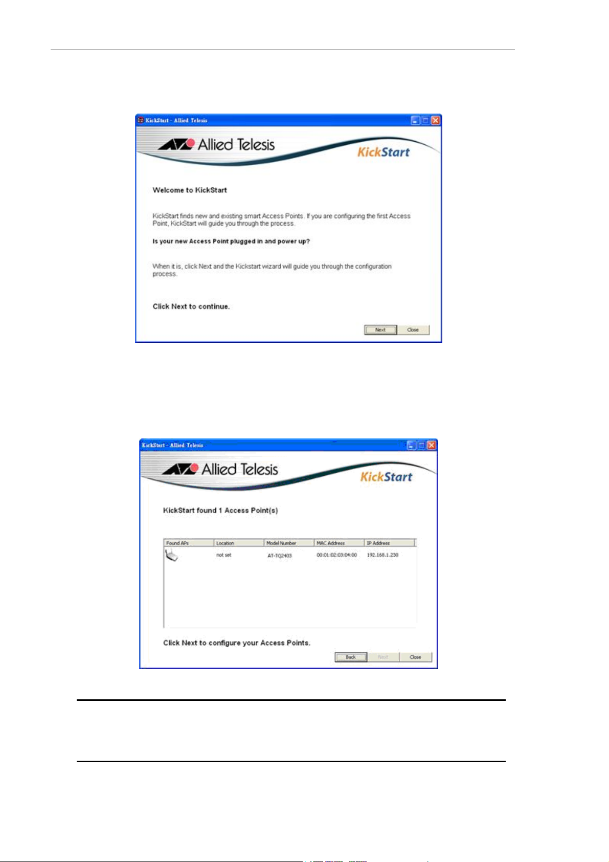
22 AT-TQ2403 - Management Software - User's Guide
2. Insert the AT-TQ2403 Wireless Access Point CD into the CD-ROM drive on your computer.
The Kick Start Welcome dialog box is displayed, as shown in Figure 1
Figure 1: Kick Start Welcome Dialog Box
3. Click Next to search for access points
Wait for the search to complete, or until Kick Start has found your new access points, as shown in
Figure 2.
Figure 2: Kick Start Search Results Dialog Box
Note: If no access points are found, Kick Start indic
troubleshooting information about your LAN and power connections. After you check the
hardware power and Ethernet connections, you can click Back to search again for access
points.
ates this and presents some
Page 23
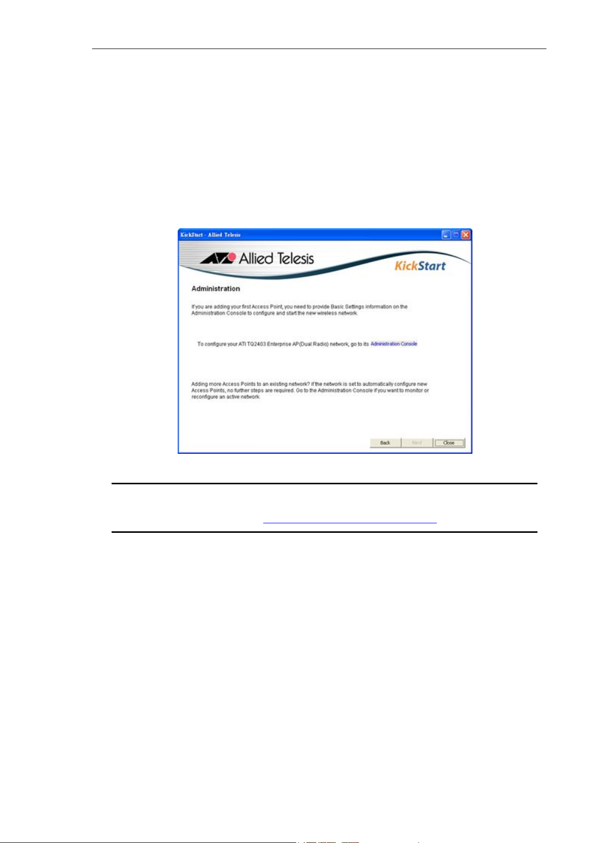
AT-TQ2403 Management Software User's Guide 23
4. Review the list of access points found
Kick Start detects the IP addresses of AT-TQ2403 Management Software. Access points are listed
with their locations, media access control (MAC) addresses, and IP addresses, as shown in Figure 2.
If you are installing the first access point on a single-access-point network, only one entry is
displayed on this screen.
5. Verify the MAC addresses against the hardware labels for each access point. This will be especially
helpful later in providing or modifying the descriptive Location name for each access point.
6. Click Next
The Administration dialog box opens, as shown in Figure 3.
Figure 3: Administration Dialog Box
The AT-TQ2403 Management Software is a centralized management tool that you can access through
the IP address for any access point in a cluster.
After your other access points are configured, you can also link to the AT-TQ2403 Management
Software web pages using the IP address for any of the other AT-TQ2403 Management Software, for
example http://IPAddressOfAccessPoint.
Note: Kick Start provides a link to the AT-TQ2403 Management Software web pages via
the IP address of the firs
types and clustering see “What Kinds of APs Can Cluster Together?
t access point of each model. (For more information about model
”.)
Logging in to the AT-TQ2403 Management Software
To access the AT-TQ2403 Management Software, perform the following procedure:
7. In the Kick Start Administration dialog box, click Administration
You are prompted for a user name and password, as shown in Figure 4.
Username: manager
Page 24
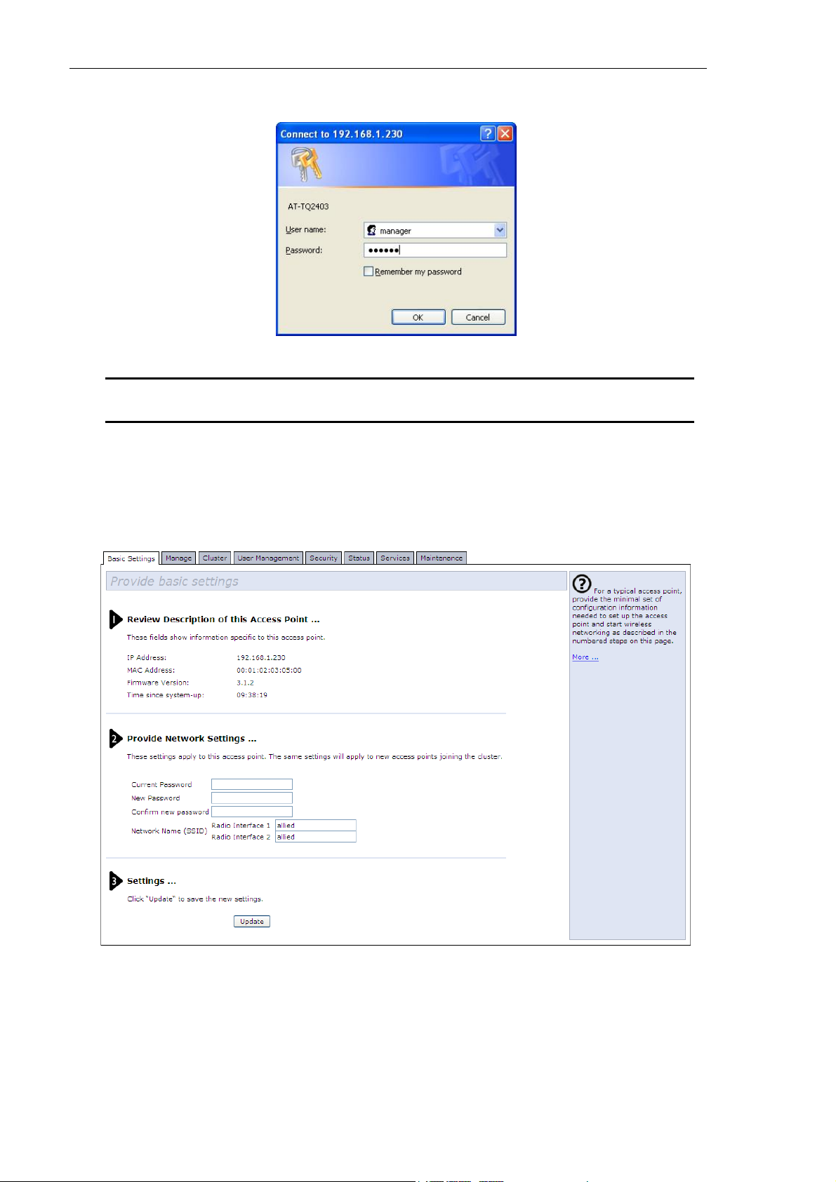
24 AT-TQ2403 - Management Software - User's Guide
Password: friend
Figure 4: Log-in Dialog Box
8. Enter the username and password and click OK
Note: The user name can not be modified.
When you log in for the first time, the Basic Settings page is displayed, as shown in Figure 5. This
page displays the global settings for all access points that are members of the cluster and, if you
specify automatic configuration, for any new access points that you add later.
Figure 5: Basic Settings Page
Page 25

AT-TQ2403 Management Software User's Guide 25
Configuring the Basic Settings and Starting the Wireless Network
Provide a minimal set of configuration information by defining the basic settings for your wireless
network. These settings are all available on the Basic Settings page in the AT-TQ2403 Management
Software, and are categorized into steps 1-3 on the web page.
Configuring the Basic Settings
9. To configure initial settings, perform the following procedure:
In the “Review Description of this Access Point” section, configure the following parameters as
necessary:
IP Address
The IP address assigned to this access point. You cannot e
already assigned (either through DHCP or statically through the Ethernet (wired)) settings as
described in “Configuring LAN or Internal Interface Ethernet Settings
MAC Address
Shows the MA
A MAC address is a permanent, unique hardware address for any device that represents an
interface to the network. The MAC address is assigned by the manufacturer. You cannot change the
MAC address. It is provided here for informational purposes as a unique identifier for an interface.
The address shown here is the MAC address for the bridge (br0). This is the address by which the
access point is known externally to other networks.
Firmware Version
Versio
n information about the firmware currently installed on the access point.
As new versions of the AT-TQ2403 Management Software firmware become available, you can
upgrade the firmware on your access points to take advantages of new features and enhancements.
For instructions on how to upgrade the firmware, see “Upgrading the Firmware
Time since system-up
C address of the access point.
dit this field because the IP address is
”.
”.
It is to show
10. In the “Provide Network Settings” section, configure the following parameters as necessary:
Current Password
As an immed
change the administrator password from the default which is “friend.” Enter the current
administrator password.
The administrator password must be an alphanumeric string of up to 8 characters. Do not use
special characters or spaces.
New Password
Enter a new adminis
the passed time since system boot up.
iate first step in securing your wireless network, Allied Telesis recommends that you
trator password. The characters you enter are displayed as “ * ” characters to
Page 26

26 AT-TQ2403 - Management Software - User's Guide
prevent others from seeing your password as you type.
Confirm New Password
Rety
pe the new administrator password to confirm that you typed it as you intended.
Network Name (SSID)
En
ter a name for the wireless network as a character string. This name will apply to all access points
on this network. As you add more access points, they will share this SSID.
The Service Set Identifier (SSID) is an alphanumeric string of up to 32 characters.
If you are connected as a wireless client to the same access point that you are administering,
resetting the SSID will causes you to lose connectivity to the access point. You will need to
reconnect to the new SSID after you save the new Network Name.
11. In the Settings section, click Update to apply t
wireless network.
After you have the wireless network up and
some wireless clients, you can add in more layers of security, add users, configure a guest interface,
and fine-tune performance settings. These features are described in the rest of this guide.
Note: The AT-TQ2403 Management Software is not designed for multiple,
si
multaneous configuration changes. If you have a network that includes multiple access
points, and more than one administrator is logged on to the AT-TQ2403 Management
Software’s web pages and making changes to the configuration, all access points in the
cluster will stay in sync but there is no guarantee that all configuration changes specified
by multiple users will be applied.
hese settings and deploy the access point as a
running and have tested against the access point with
Page 27
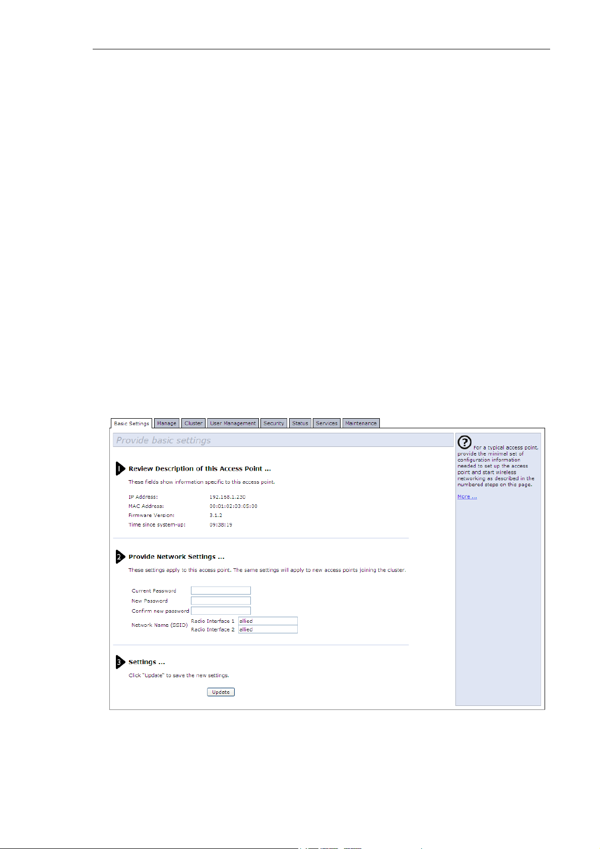
AT-TQ2403 Management Software User's Guide 27
Chapter 3: Configuring Basic Settings
The basic configuration tasks are described in the following sections:
Navigating to Basic Settings
Review / Describe the Access Point
Provide Network Settings
Update Basic Settings
Basic Settings for a Standalone Access Point
Setting User Interface Scheme Preferences
Navigation
Navigating to Basic Settings
To configure initial settings, click Basic Settings.
If you type the IP address of the access point into you browser, the Basic Settings page is the default page
that is displayed.
Fill in the fields on the Basic Settings screen as described below.
Figure 6: Basic Settings Page
Page 28

28 AT-TQ2403 - Management Software - User's Guide
Review / Describe the Access Point
Figure 7: Basic Settings Page Step 1
Field Description
IP Address Shows IP address assigned to this access point. This field is not editable
because the IP address is already assigned (either via DHCP, or statically
through the Ethernet Settings page as described in “Configuring Guest
Interface Ethernet (Wired) Settings
MAC Address Shows the MAC address of the access point.
”).
A MAC address is a permanent, unique hardware address for any device
that represents an interface to the network. The MAC address is
assigned by the manufacturer. You cannot change the MAC address. It is
provided here for informational purposes as a unique identifier for an
interface.
The address shown here is the MAC address for the bridge (br0). This is
the address by which the AP is known externally to other networks.
To see MAC addresses for Guest and Internal interfaces on the AP, see
the Status > Interfaces ta
Firmware Version Version information about the firmware currently installed on the access
point.
As new versions of the AT-TQ2403 Management Software firmware
become available, you can upgrade the firmware on your access points to
take advantages of new features and enhancements.
For instructions on how to upgrade the firmware, see “Upgrading the
Firmware
Time since system-up It is to show the passed time since system boot up.
”.
b.
Page 29

AT-TQ2403 Management Software User's Guide 29
A
Provide Network Settings
Figure 8: Basic Settings Step 2
Field Description
Current Password Enter the current administrator password. You must correctly enter the
current password before you are able to change it.
New Password Enter a new administrator password. The characters you enter will be
*
displayed as "
password as you type.
The Administrator password must be a string of up to 8 characters.
Please do not include space (' ') and any of the characters within the
parenthesis: ("$:<>'&*). The characters you input are case-sensitive.
Note:
recommend that you change the administrator password from the
default.
Confirm New Password Re-enter the new administrator password to confirm that you typed it as
intended.
Network Name (SSID) Enter a name for the wireless network as a character string. This name
will apply to all access points on this network. As you add more access
points, they will share this SSID.
The Service Set Identifier (SSID) is a string of up to 32 characters. The
characters you input are case-sensitive.
Note: If you are connected as a wireless client to the same AP that you
administering, resetting the SSID will cause you to lose connectivity
are
to the AP. You will need to reconnect to the new SSID after you save
this new setting.
" characters to prevent others from seeing your
s an immediate first step in securing your wireless network, we
Note: The AT-TQ2403 Management Software is not designed for multiple, simultaneous
configuratio
than one administrator is logged on to the Administration Web pages and making changes to
the configuration, all access points in the cluster will stay in sync but there is no guarantee that
all configuration changes specified by multiple users will be applied.
n changes. If you have a network that includes multiple access points, and more
Page 30
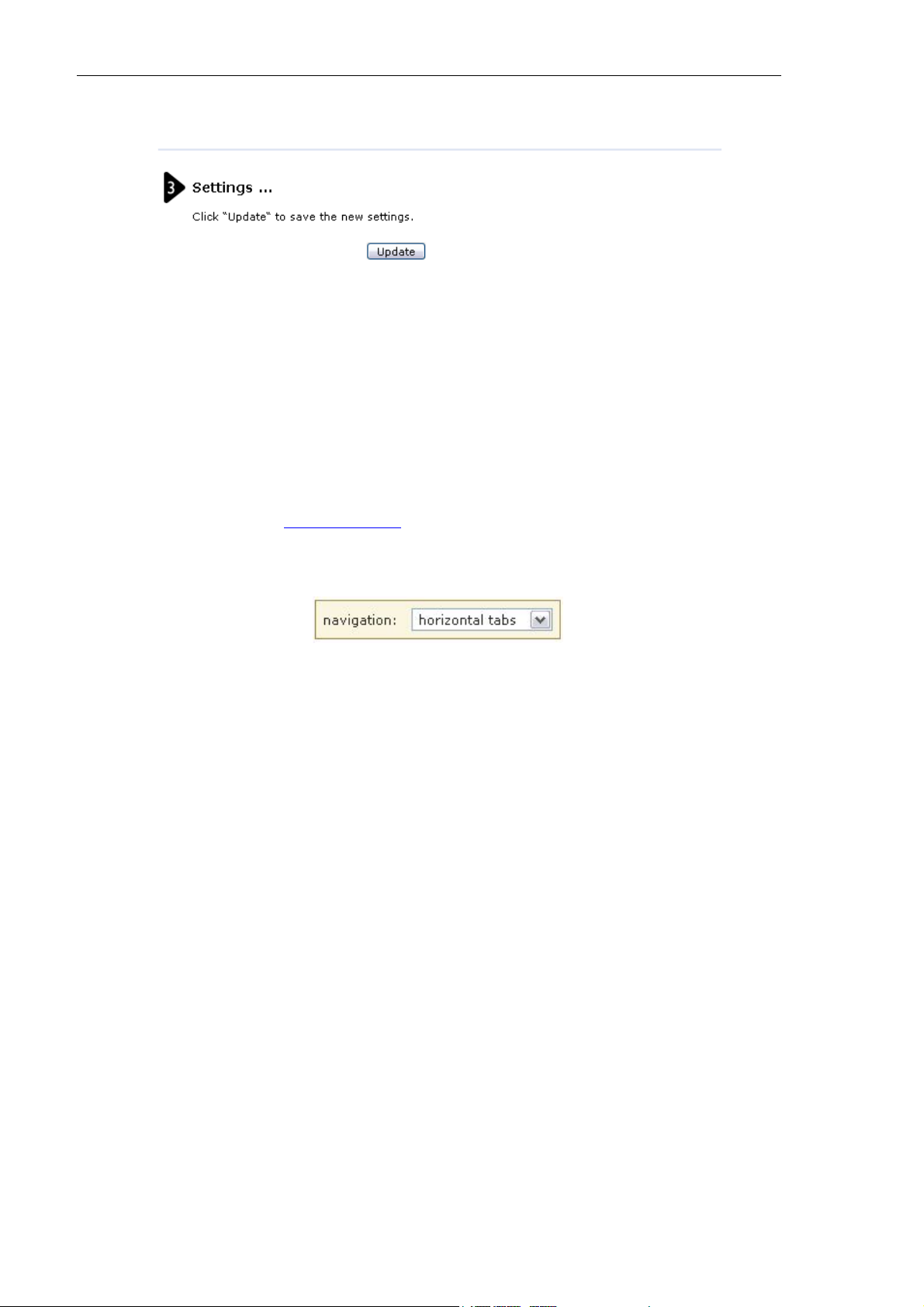
30 AT-TQ2403 - Management Software - User's Guide
Update Basic Settings
Figure 9: Basic Settings Page Step 3
n you have reviewed the new configuration, click Update to apply the settings and deploy the
Whe
access points as a wireless network.
Basic Settings for a Standalone Access Point
The Basic Settings tab for a standalone access point indicates only that the current mode is standalone. If
you want to add the current access point to an existing cluster, navigate to the Cluster > Access Point
tab.
For more information see “Starting Clustering
”.
Setting User Interface Scheme Preferences
Figure 10: Web User Interface Setting
design panel appears at the top of every AP Configuration screen enabling you to configure the
A
appearance of every web page. You can change the layout of tabs on pages by choosing between three
navigation settings.
Navigation
You use the options available in the navigation drop down list to change the layout of the tab options on
your screen.
Option Description
Horizontal Tabs Select this option to display all tabs horizontally across the top of the page.
Vertical Tabs Select this option to display all tabs vertically on the left side of your page.
Drop Down Menu Select this option to display all tabs horizontally across the top of the page.
Any sub categories will be displayed as a drop down menu beneath the main
tab.
Page 31

AT-TQ2403 Management Software User's Guide 31
Chapter 4: Managing Access Points and Clusters
The AT-TQ2403 Management Software shows current basic configuration settings for clustered access
points (location, IP address, MAC address, status, and availability) and provides a way of navigating to the
full configuration for specific APs if they are cluster members.
Standalone access points or those which are not members of this cluster do not show up in this listing. To
configure standalone access points, you must discover or know the IP address of the access point and by
using its IP address in a URL (http://IPAddressOfAccessPoint).
The following topics are covered:
Navigating to Access Points Management
Understanding Clustering
Note: The AT-TQ2403 Management Software is not designed for multiple, simultaneous
configuratio
than one administrator is logged on to the Administration Web pages and making changes to
the configuration, all access points in the cluster will stay in sync but there is no guarantee that
all configuration changes specified by multiple users will be applied.
What is a Cluster?
How Many APs Can a Cluster Support?
Only the same country domain setting can be clustered.
What Kinds of APs Can Cluster Together?
Which Settings are Shared as Part of the Cluster Configuration and Which Are Not?
Cluster Formation
n changes. If you have a network that includes multiple access points, and more
Cluster Size and Membership
Intra-Cluster Security
Understanding Access Point Settings
Modifying the Location Description
Setting the Cluster Name
Stopping Clustering
Starting Clustering
Navigating to Configuration Information for a Specific AP and Managing Standalone APs
Navigating to an AP by Using its IP Address in a URL
Page 32

32 AT-TQ2403 - Management Software - User's Guide
Navigating to Access Points Management
To view or edit information on access points in a cluster, click the Cluster > Access Points tab.
Figure 11: Access Points Setting Page
Understanding Clustering
A key feature of the AT-TQ2403 Management Software is the ability to form a dynamic,
configuration-aware group (called a cluster) with other AT-TQ2403 Management Software in a network
in the same subnet. Access points can participate in a self-organizing cluster which makes it easier for you
to deploy, administer, and secure your wireless network. The cluster provides a single point of
administration and lets you view the deployment of access points as a single wireless network rather than
a series of separate wireless devices.
What is a Cluster?
A cluster is a group of access points which are coordinated as a single group via AP administration. You
can have multiple clusters on the same subnet if they have different cluster "names".
How Many APs Can a Cluster Support?
Validation testing has verified 15 AP without enable Virtual Wireless Network function on the same
subnet. Validation testing has verified 8 AP with enable 4 Virtual Wireless Network on the same subnet.
In this test case the cluster function works well.
Only the same country domain setting can be clustered.
Note: If the devices are assigned wit
together.
h different country setting, they can not be clustered
Page 33

AT-TQ2403 Management Software User's Guide 33
What Kinds of APs Can Cluster Together?
A single AT-TQ2403 Wireless Access Point can form a cluster with itself (a "cluster of one") and with
other AT-TQ2403 Wireless Access Points of the same model. In order to be members of the same
cluster, access points must be:
Of the same Country Domain configuration
Compatible devices as designated by the manufacturer (APs must have compatible design features)
Of the same F/W Version
Of the same LAN
On the same Cluster Name
However, it is helpful to understand the clustering behavior for administration purposes:
Access points joining the cluster must be named the same. For more information on setting the
cluster name, see “Setting the Cluster Name
Access points of other brands will not join the cluster. These APs should be administered with their
own associated Administration tools.
”.
Which Settings are Shared as Part of the Cluster Configuration and Which Are Not?
Most configuration settings defined via the AT-TQ2403 Management Software Administration Web
pages will be propagated to cluster members as a part of the cluster configuration.
Settings Shared in the Cluster Configuration
The cluster configuration includes:
Network name (SSID)
Administrator password
User accounts and authentication
Wireless interface settings
Guest Welcome screen settings
Network Time Protocol (NTP) settings
QoS queue (AP EDCA parameters only)
Radio settings
Only Mode, Channel, Fragmentation Threshold, RTS Threshold and Rate Sets are synchronized across
the cluster. Beacon Interval, DTIM Period, Maximum Stations, and Transmit Power do not cluster.
Note: When Channel Planning is enabled, the radio Channel is not synced across the cluster.
See “Stopping/Starting Automatic Channel Assignment
”.
Page 34

34 AT-TQ2403 - Management Software - User's Guide
When Channel Planning is enabled, the radio Channel is not synced across the cluster.
Security settings
MAC address filtering
Settings Not Shared by the Cluster
The few exceptions (settings not shared among clustered access points) are the following, most of which
by nature must be unique:
IP addresses
MAC addresses
Location descriptions
Load Balancing settings
WDS bridges
Ethernet (Wired) Settings, including enabling or disabling Guest access
Guest interface configuration
Settings that are not shared must be configured individually on the Administration pages for each access
point. To get to the Administration pages for an access point that is a member of the current cluster, click
on its IP Address link on the Cluster > Access Points page of the current AP.
Cluster Formation
A cluster is formed when the first AP is deployed with clustering enabled. The AP attempts to
rendezvous with an existing cluster.
If it is unable to locate any other APs on the subnet with the same cluster name, then it establishes a new
cluster on its own.
When AT-TQ2403 enables cluster function, it sends out its configuration file to all the devices in the
clustered group.
If there is more than one AT-TQ2403 in the clustered group, the last-joined AT-TQ2403 shares its
configuration with other AT-TQ2403 in the group.
Cluster Size and Membership
Validation testing has verified 15 AP without enable VWN function on the same subnet. Validation testing
has verified 8 AP with enable 4 VWN on the same subnet. In this test case the cluster function works
well. Cluster membership is determined by:
Cluster Name - APs with the same name will join the same cluster. (see “Setting the Cluster Name
Whether clustering is enabled - Only APs for which clustering is enabled will join a cluster. (see
“Starting Clustering
” and “Stopping Clustering”)
”)
Page 35

AT-TQ2403 Management Software User's Guide 35
Intra-Cluster Security
For purposes of ease-of-use, the clustering component is designed to let new devices join a cluster
without strong authentication. However, communications of all data between access points in a cluster is
protected against casual eavesdropping using Secure Sockets Layer (typically referred to as SSL). The
assumption is that the private wired network to which the devices are connected is secure. Both the
cluster configuration file and the user database are transmitted among access points using SSL.
Understanding Access Point Settings
The Access Points tab provides information about all access points in the cluster.
From this page, you can view location descriptions, MAC addresses, IP addresses, enable (activate) or
disable (deactivate) clustered access points, and remove access points from the cluster. You can also
modify the location description for an access point.
The IP address links provide a way to navigate to configuration settings and data on an access point.
Stand-alone access points (those which are not members of the cluster) are not shown on this page.
Figure 12: Access Points Setting Page
he following table describes the access point settings and information display in detail.
T
Field Description
Location Description of where the access point is physically located.
Page 36

36 AT-TQ2403 - Management Software - User's Guide
Field Description
Mac Address Media Access Control (MAC) address of the access point.
A MAC address is a permanent, unique hardware address for any device that
represents an interface to the network. The MAC address is assigned by the
manufacturer. You cannot change the MAC address. It is provided here for
informational purposes as a unique identifier for the access point.
The address shown here is the MAC address for the bridge (br0). This is the
address by which the AP is known externally to other networks.
To see MAC addresses for Guest and Internal interfaces on the AP, see the
Status > Interfaces ta
IP Address Specifies the IP address for the access point. Each IP address is a link to the
AT-TQ2403 Management Software
the links to navigate to the Administration Web pages for a specific access point.
This is useful for viewing data on a specific access point to make sure a cluster
member is picking up cluster configuration changes, to configure advanced
settings on a particular access point, or to switch a standalone access point to
cluster mode.
b.
web pages for that access point. You can use
Modifying the Location Description
To make modifications to the location description:
1. Navigate to the Cluster > Access Points tab.
2. Under the Clustering Options section
3. This text max length limit is 128.
4. Click the Update but
ton to apply the changes.
, type the new location of the AP in the Location field.
Setting the Cluster Name
To set the name of the cluster you want your AP to join, do the following:
1. Navigate to the Cluster > Access Points tab.
2. Under the Clustering Options section, type the new cluster name in the Cluster Name field.
3. The Cl
uster name is up to 128 characters long.
4. Click the Update button to apply the changes.
Note: If you want multiple APs to join a particular cluster, all these APs should have the
same Clus
the AP will not be able to join the cluster.
ter Name specified in the Cluster Name field. If the cluster name is different
Page 37

AT-TQ2403 Management Software User's Guide 37
Stopping Clustering
To stop clustering and remove a particular access point from a cluster, do the following.
1. Go to the Administration Web pages for the access point you want to remove from the cluster.
2. Click the Cluster > Access Points tab.
3. Click the Stop Clustering button to remove the access point from the Cluster.
The c
hange will be reflected under Status for that access point; the access point will now show as
standalone (instead of cluster).
Note: In some situations it is possible for the cluster to become out of sync. If after removing
an access point from t
incomplete display; refresh your browser. If you still experience problems, refer to the
information on Cluster Recovery in “Appendix B: Troubleshooting
he cluster, the AP list still reflects the deleted AP or shows an
”.
Starting Clustering
To start clustering and add a particular access point to a cluster, do the following.
1. Go to the Administration Web pages for the standalone access point. (See “Navigating to an AP by
Using its IP Address in a URL”.)
The Administration Web pages for the standalone access point are displayed.
2. Click the Cluster > Access Points tab for the standalone access point.
3. Click the Start Clustering button.
The access poi
> Access Points tab page.
nt is now a cluster member. It appears in the list of clustered access points on the Cluster
Note: In some situations it is possible for the cluster to become out of sync. If after removing
an access point from t
incomplete display; refer to the information on Cluster Recovery in “Appendix B:
Troubleshooting”.
he cluster, the AP list still reflects the deleted AP or shows an
Navigating to Configuration Information for a Specific AP and Managing Standalone APs
In general, the AT-TQ2403 Management Software is designed for central management of clustered
access points. For access points in a cluster, all access points in the cluster reflect the same configuration.
In this case, it does not matter which access point you actually connect to for administration.
There may be situations, however, when you want to view or manage information on a particular access
point. For example, you might want to check status information such as client associations or events for
an access point. Or you might want to configure and manage features on an access point that is running
in standalone mode. In these cases, you can navigate to the AT-TQ2403 Management Software web
interface for individual access points by clicking the IP address links on the Access Points page.
Page 38

38 AT-TQ2403 - Management Software - User's Guide
All clustered access points are shown on the Cluster > Access Points page. To navigate to clustered
access points, you can simply click on the IP address for a specific cluster member shown in the list.
Navigating to an AP by Using its IP Address in a URL
You can also link to the Administration Web pages of a specific access point, by entering the IP address
for that access point as a URL directly into a Web browser address bar in the following form:
http://IPAddressOfAccessPoint
Where I
configure.
For standalone access points, this is the only way to navigate to their configuration information.
If you do not know the IP address of a standalone access point, use Kick Start to find all access points on
the network and you should be able to derive which ones are standalone by comparing Kick Start findings
with access points listed on the Cluster > Access Points page. The Access points that Kick Start finds
tha
PAddressOfAccessPoint is the address of the particular access point you want to monitor or
t are not shown on this page are probably standalone access points.
Page 39

AT-TQ2403 Management Software User's Guide 39
Chapter 5: Managing User Accounts
The AT-TQ2403 Management Software includes user management capabilities for controlling client
access to access points.
User management and authentication must always be used in conjunction with the following two security
modes, which require use of a RADIUS server for user authentication and management.
IEEE 802.1x mode (see “IEEE 802.1x
WPA with RADIUS mode (see “WPA Enterprise
You have the option of using either the internal RADIUS server embedded in the AT-TQ2403
Management Software or an external RADIUS server that you provide. If you use the embedded RADIUS
server, use this Administration Web page on the access point to set up and manage user accounts. If you
are using an external RADIUS server, you will need to set up and manage user accounts on the
Administrative interface for that server.
On the User Management page, you can create, edit, remove, and view client user accounts. Each user
account consists of a user name and password. The set of users specified here represent approved clients
that can log in and use one or more access points to access local and possibly external networks via your
wireless network.
The following topics are covered:
Navigating to User Management for Clustered Access Points
Note: Users specified here are clients of the access point(s) who
connectivity hub, not administrators of the wireless network. Only those with the
administrator username and password and knowledge of the administration URL can log in as
an administrator and view or modify configuration settings.
” in Configuring Security)
” in Configuring Security)
use the APs as a
Viewing User Accounts
Adding a User
Editing a User Account
Enabling and Disabling User Accounts
Removing a User Account
Backing Up and Restoring a User Database
Navigating to User Management for Clustered Access Points
To set up or modify user accounts, click the User Management tab.
Page 40

40 AT-TQ2403 - Management Software - User's Guide
Figure 13: User Management Page
Viewing User Accounts
User accounts are shown at the top of the screen under "User Accounts". The Username, Real name and
Status (enabled or disabled) of the user are shown. You make modifications to an existing user account
by first selecting the checkbox next to a user name and then choosing an action. (See “Editing a User
Account”.)
Adding a User
To create a new user, do the following:
1. Under "Add a User", provide information in the following fields.
Field Description
Username Provide a user name.
Usernames are strings of with 3~237 characters. Please do not include any of the
characters within the parenthesis: ("<>'&).
Real Name For information purposes, provide the user’s full name.
Real name is a string of up to 256 characters. Please do not include any of the
characters within the parenthesis: ("<>'&).
If you do not specify this field, the Username will be saved as Real name.
Page 41

AT-TQ2403 Management Software User's Guide 41
Field Description
Password Specify a password for this user.
Passwords are strings of 4 to 256 characters. Please do not include '<' and '&'.
2. When you have filled in the fields, click Add Account to add the account.
The new user is then displayed in "User Accounts". The user account is enabled by default when you
first create it.
Note: A limit of 100 user accounts per access point is imposed by the Adminis
interface. Network usage may impose a more practical limit, depending upon the demand
from each user.
tration user
Editing a User Account
Once you have created a user account, it is displayed under "User Accounts" at the top of the User
Management Administration Web page. To make modifications to an existing user account, first click
the checkbox next to the username so that the box is checked.
Figure 14: Cluster Settings Page Detail
Then, c
hoose an action such as Edit, Enable, Disable, or Remove.
Enabling and Disabling User Accounts
A user account must be enabled for the user to log on as a client and use the access point.
You can enable or disable any user account. With this feature, you can maintain a set of user accounts and
authorize or prevent users from accessing the network without having to remove or re-create accounts.
This can come in handy in situations where users have an occasional need to access the network. For
example, contractors who do work for your company on an intermittent but regular basis might need
network access for 3 months at a time, then be off for 3 months, and back on for another assignment.
You can enable and disable these user accounts as needed, and control access as appropriate.
Enabling a User Account
To enable a user account, click the checkbox next to the username and click Enable.
Page 42

42 AT-TQ2403 - Management Software - User's Guide
A user with an account that is enabled can log on to the wireless access points in your network as a client.
Disabling a User Account
To disable a user account, click the checkbox next to the username and click Disable.
A user with an account that is disabled cannot log on to the wireless access points in your network as a
client. However, the user remains in the database and can be enabled later as needed.
Removing a User Account
To remove a user account, click the checkbox next to the username and click Remove.
If you think you might want to add this user back in at a later date, you might consider disabling the user
rather than removing the account altogether.
Backing Up and Restoring a User Database
You can save a copy of the current set of user accounts to a backup configuration file. The backup file can
be used at a later date to restore the user accounts on the AP to the previously saved configuration.
Backing Up the User Database
To create a backup copy of the user accounts for this access point:
1. Click the backup or restore the user database link.
A File Download or Open dialog is displayed.
2. Choose the Save option on this first dialog.
This brings up a file browser.
3. Use the file browser to navigate to the directory where you want to save the file, and click OK to
save the file.
You can keep the default file name (wirelessUsers.ubk) or rename the backup file, but be sure to
save the file with a .ubk extension.
Restoring a User Database from a Backup File
To restore a user database from a backup file:
1. Select the backup configuration file you want to use, either by typing the full path and file name in
the Restore field or click Browse and select the file.
(Only those files that were created with the User Database Backup function and saved as .ubk
backup configuration files are valid to use with Restore; for example, wirelessUsers.ubk.)
2. Click the Restore button.
When the backup restore process is complete, a message is shown to indicate that the user
database has been successfully restored. (This process is not time-consuming; the restore should
complete almost immediately.)
3. Click the User Management tab to see the restored user accounts.
Page 43

AT-TQ2403 Management Software User's Guide 43
Chapter 6: Session Monitoring
The AT-TQ2403 Management Software provides real-time session monitoring information including
which clients are associated with a particular access point, data rates, transmit/receive statistics, signal
strength, and idle time. The following Session Monitoring topics are covered here:
Navigating to Session Monitoring
Understanding Session Monitoring Information
Sorting Session Information
Refreshing Session Information
Navigating to Session Monitoring
To view session monitoring information, click the Cluster > Sessions tab.
Figure 15: Sessions Setting Page
Understanding Session Monitoring Information
The Sessions page shows information on client stations associated with access points in the cluster. Each
client is identified by user name and user MAC address, along with the AP (location) to which it is
currently connected.
To view a particular statistic for client sessions, select an item from the Display drop-down list and click
Go. You can view information on Idle Time, Data Rate, Signal, Utilization, and so on; all of which are
described in detail in the table below.
A "session" in this context is the period of time in which a user on a client device (station) with a unique
MAC address maintains a connection with the wireless network. The session begins when the client logs
on to the network, and the session ends when the client either logs off intentionally or loses the
connection for some other reason.
Page 44

44 AT-TQ2403 - Management Software - User's Guide
Details about the session information shown is described below.
Field Description
User Indicates the client user name of IEEE 802.1x clients.
AP Location Indicates the location of the access point.
User Mac Indicates the MAC address of the user’s client device (station).
Note: A sessio
particular access point. A client network connection can shift from one clustered AP to
another within the context of the same session. A client station can roam between APs and
maintain the session.
n is not the same as an association, which describes a client connection to a
Note: This field is relevant only for clients that are connected to APs using IEEE
80
2.1x security mode and local authentication server. (For more information about
this mode, see “IEEE 802.1x
server or other security modes, no user name will be shown here.
This is derived from the location description specified on the Basic Settings tab.
A MAC address is a hardware address that uniquely identifies each node of a
network.
”.) For clients of APs using IEEE 802.1x with RADIUS
Idle Indicates the amount of time this station has remained inactive.
A station is considered to be "idle" when it is not receiving or transmitting data.
Rate (Mbps) The speed at which this access point is transferring data to the specified client.
The data transmission rate is measured in megabits per second (Mbps).
This value should fall within the range of the advertised rate set for the IEEE 802.1x
mode in use on the access point. For example, 6 to 54Mbps for 802.11a.
Signal Indicates the strength of the radio frequency (RF) signal the client receives from the
access point.
The measure used for this is an IEEE 802.1x value known as Received SignalStrength
Indication (RSSI), and will be a value between 0 and 100.
RSSI is determined by an IEEE 802.1x mechanism implemented on the network
interface card (NIC) of the client station.
Utilization Utilization rate for this station.
For example, if the station is "active" (transmitting and receiving data) 90% of the
time and inactive 10% of the time, its "utilization rate" is 90%.
Page 45

AT-TQ2403 Management Software User's Guide 45
Field Description
Rx Total Indicates number of total packets received by the client during the current
session.
Tx Total Indicates number of total packets transmitted to the client during this session.
Error Rate Indicates the percentage of time frames dropped during transmission on this
access point.
Sorting Session Information
To order (sort) the information shown in the tables by a particular indicator, click on the column label by
which you want to order things. For example, if you want to see the table rows ordered by Utilization
rate, click on the Utilization column label. The entries will be sorted by Utilization rate.
Refreshing Session Information
You can force an update of the information displayed on the Session Monitoring page by clicking the
Refresh button.
Page 46

46 AT-TQ2403 - Management Software - User's Guide
Chapter 7: Channel Management
The following Channel Management topics are covered here:
Navigating to Channel Management
Understanding Channel Management
How it Works in a Nutshell
For the Curious: More About Overlapping Channels
Example: A Network Before and After Channel Management
Configuring and Viewing Channel Management Settings
Stopping/Starting Automatic Channel Assignment
Viewing Current Channel Assignments and Setting Locks
Update Current Channel Settings (Manual Setting)
Viewing Last Proposed Set of Changes
Configuring Advanced Settings (Customizing and Scheduling Channel Plans)
Update Advanced Settings
Navigating to Channel Management
To view session monitoring information, click the Cluster > Channel Management tab.
Figure 16: Channel Management Setting Page
Page 47

AT-TQ2403 Management Software User's Guide 47
Understanding Channel Management
When Channel Management is enabled, the AT-TQ2403 AP automatically assigns radio channels used by
clustered access points to reduce mutual interference (or interference with other access points outside
of its cluster). This maximizes Wi-Fi bandwidth and helps maintain the efficiency of communication over
your wireless network.
(You must start channel management to get automatic channel assignments; it is disabled by default on a
new AP. See “Stopping/Starting Automatic Channel Assignment
How it Works in a Nutshell
At a specified interval (the default is 1 hour) or on demand (click Update), the Channel Manager maps
APs to channel use and measures interference levels in the cluster. If significant channel interference is
detected, the Channel Manager automatically re-assigns some or all of the APs to new channels per an
efficiency algorithm (or automated channel plan).
For the Curious: More About Overlapping Channels
The radio frequency (RF) broadcast Channel defines the portion of the radio spectrum that the radio on
the access point uses for transmitting and receiving. The range of available channels for an access point is
determined by the IEEE 802.11 mode (also referred to as band) of the access point.
”.)
IEEE 802.11 b/g support consecutive channels (for example, U.S uses channels 1 through 11) inclusive,
while IEEE 802.11a mode supports a larger set of non-consecutive channels.
Interference can occur when multiple access points within range of each other are broadcasting on the
same or overlapping channels. The impact of this interference on network performance can intensify
during busy times when a large amount of data and media traffic is competing for bandwidth.
The Channel Manager detects which bands (b/g or a) clustered APs are on, and uses a predetermined
collection of channels that will not mutually interfere. For the "b/g" radio band, the classical set of noninterfering channels is 1, 6, and 11. Channels 1, 4, 8, 11 produce minimal overlap. A similar set of
non-interfering channels is used for the "a" radio band, which includes all channels for that mode since
they are not overlapping.
Example: A Network Before and After Channel Management
Without automated channel management, channel assignments to clustered APs might be made on
consecutive channels, which would overlap and cause interference. For example, AP1 could be assigned
to channel 6, AP2 to channel 6, and AP3 to channel 5 as shown in below figure. APs can broadcast on
overlapping channels without automated channel management.
Figure 17: Before Channel Management Enable
Page 48

48 AT-TQ2403 - Management Software - User's Guide
With automated channel management, APs in the cluster are automatically re-assigned to
non-interfering
channels as shown in below figure.
Figure 18: After Channel Management Enable
Configuring and Viewing Channel Management Settings
The Channel Management page shows previous, current, and planned channel assignments for clustered
access points. By default, automatic channel assignment is disabled. You can start channel management to
optimize channel usage across the cluster on a scheduled interval.
From this page, you can view channel assignments for all APs in the cluster, stop/start automatic channel
management, and manually "update" the current channel map (APs to channels). On a manual update, the
Channel Manager will assess channel usage and, if necessary, re-assign APs to new channels to reduce
interference based on the current Advanced Settings.
By using the Advanced settings you can modify the interference reduction potential that triggers channel
re-assignment, change the schedule for automatic updates, and re-configure the channel set used for
assignments.
The following sections describe how to configure and use channel management on your network:
Stopping/Starting Automatic Channel Assignment
Viewing Current Channel Assignments and Setting Locks
Update Current Channel Settings (Manual Setting)
Viewing Last Proposed Set of Changes
Configuring Advanced Settings (Customizing and Scheduling Channel Plans)
Update Advanced Settings
Stopping/Starting Automatic Channel Assignment
By default, automatic channel assignment is disabled (off).
Click Start to resume automatic channel assignment.
Page 49

AT-TQ2403 Management Software User's Guide 49
Figure 19: After Channel Management Enable
n automatic channel assignment is enabled, the Channel Manager periodically maps radio
Whe
channels used by clustered access points and, if necessary, re-assigns channels on clustered APs to
reduce interference (with cluster members or other APs outside the cluster).
Click Stop to stop automatic channel assignment. (No channel usage maps or channel
re-assignments will be made. Only manual updates will affect the channel assignment.)
Note: Channel Management overrides the default cluster behavior, which is to
synchro
enabled, the radio Channel is not synced across the cluster to other APs. See the note
under Radio Settings in “Settings Shared in the Cluster Configuration
nize radio channels of all APs across a cluster. When Channel Management is
”.
Viewing Current Channel Assignments and Setting Locks
The "Current Channel Assignments" shows a list of all access points in the cluster by IP Address. The
display shows the band on which each AP is broadcasting, the current channel used by each AP, and an
option to "lock" an AP on its current radio channel so that it cannot be re-assigned to another. Details
about Current Channel Settings are provided below.
Field Description
IP Address Specifies the IP Address for the access point.
Radio Indicates the MAC address of the access point.
Band Indicates the band (b/g or a) on which the access point is broadcasting.
Channel Indicates the radio Channel on which this access point is currently broadcasting.
Locked Click Locked if you want this access point to remain on the current channel.
When the “Locked” checkbox is checked (enabled) for an access point, automated
channel management plans will not re-assign the AP to a different channel as a part
of the optimization strategy. For 5GHz band, because of DFS function (See
“802.11h Regulatory Domain Control
APs.
If you click Update, you will see that locked APs show the same channel for
"Current Channel" and "Proposed Channel". Locked APs will keep their current
channels.
”), you might fail to lock the channel for the
Update Current Channel Settings (Manual Setting)
You can run a manual channel management update at any time by clicking Update under the Advanced
display.
Page 50

50 AT-TQ2403 - Management Software - User's Guide
Viewing Last Proposed Set of Changes
The Proposed Channel Assignments shows the last channel plan. The plan lists all access points in the
cluster by IP Address, and shows the proposed channels for each AP. Locked channels will not be
re-assigned and the optimization of channel distribution among APs will take into account the fact that
locked APs must remain on their current channels. APs that are not "Locked" may be assigned to
different channels than they were previously using, depending on the results of the plan.
Field
IP Address Specifies the IP Address for the access point.
Current Indicates the radio channel on which this access point is currently broadcasting.
Proposed
Channel
Description
Indicates the radio channel to which this access point would be re-assigned if the
Channel Plan is executed.
Configuring Advanced Settings (Customizing and Scheduling Channel Plans)
If you use Channel Management as provided (without updating Advanced Settings), channels are
automatically fine-tuned once every hour if interference can be reduced by 25 percent or more. Channels
will be re-assigned even if the network is busy. The appropriate channel sets will be used (b/g for APs
using IEEE 802.11b/g and a for APs using IEEE 802.11a).
These defaults are designed to satisfy most scenarios where you would need to implement channel
management.
You can use “Advanced Settings” to modify the interference reduction potential that triggers channel reassignment, change the schedule for automatic updates, and re-configure the channel set used for
assignments.
Field Description
Advanced Click "Advanced" toggle to show / hide display settings that modify
timing and details of the channel planning algorithm.
By default, these settings are hidden.
Page 51

AT-TQ2403 Management Software User's Guide 51
t
Field Description
Change channels if
interference is reduced
by at least
Determine if there is
better set of channel
settings every
Specify the minimum percentage of interference reduction a proposed
plan must achieve in order to be applied. The default is 25 percent.
Use the drop-down menu to choose percentages ranging from 5% to 75%.
This setting lets you set a gating factor for channel reassignment so that
the network is not continually disrupted for minimal gains in efficiency.
For example, if channel interference must be reduced by 75 percent and
the proposed channel assignments will only reduce interference by 30
percent, then channels will not be re-assigned. However; if you re-se
the
minimal channel interference benefit to 25 percent and click "Update",
the proposed channel plan will be implemented and channels re-assigned
as needed.
Use the drop-down menu to specify the schedule for automated updates.
A range of intervals is provided, from "1 Minute" to "6 Months". The
default is "1 hour" (channel usage re-assessed and the resulting channel
plan applied every hour).
Note: Keep in mind that every time the channel planner is triggered, the
AP’s operating channel may change and clients will have to re-associate.
Therefore, setting the planning interval for less than an hour can
destabilize wireless access for clients.
Update Advanced Settings
Click Update, under “Advanced settings”, to apply these settings.
Advanced settings will take affect when they are applied, and influence how automatic channel
management is performed. (The new interference reduction minimum, scheduled tuning interval, channel
set, and network busy settings will be taken into account for automated and manual updates.)
Page 52

52 AT-TQ2403 - Management Software - User's Guide
Chapter 8: Wireless Neighborhood
The Wireless Neighborhood view shows those access points within range of any access point in the
cluster. This page provides a detailed view of neighboring access points including identifying information
(SSIDs and MAC addresses) for each, cluster status (which are members and non-members), and
statistical information such as the channel each AP is broadcasting on, signal strength, and so forth.
The following topics are covered here:
Navigating to Wireless Neighborhood
Understanding Wireless Neighborhood Information
Viewing Wireless Neighborhood
Viewing Details for a Cluster Member
Navigating to Wireless Neighborhood
To view the Wireless Neighborhood, click the Cluster > Wireless Neighborhood tab.
Figure 20: Wireless Neighborhood Page
Page 53

AT-TQ2403 Management Software User's Guide 53
Understanding Wireless Neighborhood Information
The Wireless Neighborhood shows all access points within range of every member of the cluster, shows
which access points are within range of which cluster members, and distinguishes between cluster
members and non-members.
For each neighbor access point, the Wireless Neighborhood view shows identifying information (SSID or
Network Name, IP Address, MAC address) along with radio statistics (signal strength, channel, beacon
interval). You can click on an AP to get additional statistics about the APs in radio range of the currently
selected AP.
The Wireless Neighborhood view can help you:
Detect and locate unexpected (or rogue) access points in a wireless domain so that you can take
action to limit associated risks.
Verify coverage expectations. By assessing which APs are visible at what signal strength from other
APs, you can verify that the deployment meets your planning goals.
Detect faults. Unexpected changes in the coverage pattern are evident at a glance in the color coded
table.
Viewing Wireless Neighborhood
Details about Wireless Neighborhood information shown is described below.
Field Description
Display
Neighboring APs
Click one of the following radio buttons to change the view:
In cluster - Shows only neighbor APs that are members of the cluster
Not in cluster - Shows only neighbor APs that are not cluster members
Both - Shows all neighbor APs (cluster members and non-members)
Page 54

54 AT-TQ2403 - Management Software - User's Guide
A
Field Description
Cluster The Cluster list at the top of the table shows IP addresses for all access points in the
cluster. (This is the same list of cluster members shown on the Cluster > Access
Points tab described in “Navigating to Access Points Management
”.)
If there is only one AP in the cluster, only a single IP address column will be displayed
here; indicating that the AP is "clustered with itself".
You can click on an IP address to view more details on a particular AP as shown in Figure
below.
ccess points which are neighbors of one or more of the clustered APs are listed
in the left column by SSID (Network Name). An access point which is detected as a
neighbor of a cluster member can also be a cluster member itself. Neighbors who are
also cluster members are always shown at the top of the list with a heavy bar above and
include a location indicator. The colored bars to the right of each AP in the Neighbors
list shows the signal strength for each of the neighbor APs as detected by the cluster
member whose IP address is shown at the top of the column:
Dark Blue Bar - A dark blue bar and a high signal strength number (for example 50)
icates good signal strength detected from the Neighbor seen by the AP whose IP
ind
address is listed above that column.
Lighter Blue Bar - A lighter blue bar and a lower signal strength number (for example
20 or lo
wer) indicates medium or weak signal strength from the Neighbor seen by the
AP whose IP address is listed above that column.
White Bar - A white bar and the number 0 indicates that a neighboring AP that was
detected by one of the cluster
members cannot be detected by the AP whose IP address
is listed above that column.
Light Gray Bar - A light
gray bar and no signal strength number indicates a Neighbor
that is detected by other cluster members but not by the AP whose IP address is listed
above that column.
Dark Gray Bar - A dark gray bar and no signal strengt
h number indicates this is the AP
whose IP address is listed above that column (since it is not applicable to show how well
the AP can detect itself).
Page 55

AT-TQ2403 Management Software User's Guide 55
Viewing Details for a Cluster Member
To view details on a cluster member AP, click on the IP address of a cluster member at the top of the
page.
Figure 21: Cluster Member Setting Detail
llowing table explains the details shown about the selected AP.
The fo
Field Description
SSID The Service Set Identifier (SSID) for the access point.
A Guest network and an internal network running on the same access point must
always have two different network names.
MAC Address Shows the MAC address of the neighboring access point.
A MAC address is a hardware address that uniquely identifies each node of a
network.
Page 56

56 AT-TQ2403 - Management Software - User's Guide
Field Description
Channel Shows the channel on which the access point is currently broadcasting.
The Channel defines the portion of the radio spectrum that the radio uses for
transmitting and receiving.
The channel is set in Manage > Radio. (See “Configuring Radio Settings
”.)
Rate Shows the rate (in megabits per second) at which this access point is currently
transmitting.
The current rate will always be one of the rates shown in Supported Rates.
Signal Indicates the strength of the radio signal emitting from this access point as
measured in decibels (dB).
Beacon Interval Shows the Beacon interval being used by this access point.
Beacon frames are transmitted by an access point at regular intervals to
announce the existence of the wireless network. The default behavior is to
send a beacon frame once every 100 milliseconds (or 10 per second).
The Beacon Interval is set on Manage > Radio. (See “Configuring Radio
Settings”)
Beacon Age Shows the date and time of the most recent beacon that was transmitted from
the access point.
Page 57

AT-TQ2403 Management Software User's Guide 57
Chapter 9: Configuring Security
The following sections describe how to configure Security settings on the AT-TQ2403 Management
Software:
Understanding Security Issues on Wireless Networks
How Do I Know Which Security Mode to Use?
Comparison of Security Modes for Key Management, Authentication and Encryption
Algorithms
Does Prohibiting the Broadcast SSID Enhance Security?
Navigating to Security Settings
Configuring Security Settings
Updating Settings
Understanding Security Issues on Wireless Networks
Wireless mediums are inherently less secure than wired mediums. For example, an Ethernet NIC
transmits its packets over a physical medium such as coaxial cable or twisted pair. A wireless NIC
broadcasts radio signals over the air allowing a wireless LAN to be easily tapped without physical access
or sophisticated equipment. A hacker equipped with a laptop, a wireless NIC, and a bit of knowledge can
easily attempt to compromise your wireless network. One does not even need to be within normal
range of the access point. By using a sophisticated antenna on the client, a hacker may be able to connect
to the network from many miles away.
The AT-TQ2403 Management Software provides a number of authentication and encryption schemes to
ensure that your wireless infrastructure is accessed only by the intended users. The details of each
security mode are described in the sections below.
See also the related topic, “Appendix A: Security Settings on Wireless Clients and RADIUS Server
Setup”.
How Do I Know Which Security Mode to Use?
In general, we recommend that on your Internal network you use the most robust security mode that is
feasible in your environment. When configuring security on the access point, you first must choose the
security mode, then in some modes an authentication algorithm, and whether to allow clients not using
the specified security mode to associate.
Wi-Fi Protected Access (WPA) with Remote Authentication Dial-In User Service (RADIUS) using the
CCMP (AES) encryption algorithm provides the best data protection available and is clearly the best
choice if all client stations are equipped with WPA supplicants. However, backward compatibility or
interoperability issues with clients or even with other access points may require that you configure WPA
with RADIUS with a different encryption algorithm or choose one of the other security modes.
That said, however, security may not be as much of a priority on some types of networks. If you are
simply providing internet and printer access, as on a guest network, setting the security mode to None
(Plain-text) may be the appropriate choice. To prevent clients from accidentally discovering and
connecting to your network, you can disable the broadcast SSID so that your network name is not
advertised. If the network is sufficiently isolated from access to sensitive information, this may offer
enough protection in some situations. This level of protection is the only one offered for guest networks,
Page 58

58 AT-TQ2403 - Management Software - User's Guide
and also may be the right convenience trade-off for other scenarios where the priority is making it as
easy as possible for clients to connect. (See “Does Prohibiting the Broadcast SSID Enhance Security?
Following is a brief discussion of what factors make one mode more secure than another, a description
of each mode offered, and when to use each mode.
”)
Comparison of Security Modes for Key Management, Authentication and Encryption Algorithms
Three major factors that determine the effectiveness of a security protocol are:
How the protocol manages keys
Presence or absence of integrated user authentication in the protocol
Encryption algorithm or formula the protocol uses to encode/decode the data
Following is a list of the security modes available on the AT-TQ2403 Management Software
along with a description of the key management, authentication, and encryption algorithms used
in each mode. We include some suggestions as to when one mode might be more appropriate
than another.
When to Use Unencrypted (No Security)
When to Use Static WEP
When to Use IEEE 802.1x
When to Use WPA Personal
When to Use WPA Enterprise
When to Use Unencrypted (No Security)
Setting the security mode to None (Plain-text) by definition provides no security. In this mode, the
data is not encrypted but rather sent as "plain-text" across the network. No key management, data
encryption or user authentication is used.
Recommendations
ncrypted mode, i.e. None (Plain-text), is not recommended for regular use on the Internal
Une
network because it is not secure. This is the only mode in which you can run the Guest network, which
is by definition an insecure LAN, always virtually separated from any sensitive information on the Internal
LAN.
Therefore, only set the security mode to None (Plain-text) on the Guest network, and on the Internal
network for initial setup, testing, or problem solving only.
See Also
For infor
“Configuring Security Settings”.
mation on how to configure unencrypted security mode, see “None (Plain-text)
” on under
When to Use Static WEP
Static WEP (Wired Equivalent Privacy) is a data encryption protocol for 802.11 wireless networks. All
wireless stations and access points on the network are configured with a static 64-bit (40-bit secret key
Page 59

AT-TQ2403 Management Software User's Guide 59
A
4-bit initialization vector (IV)) or 128-bit (104-bit secret key + 24-bit IV) Shared Key for data
+ 2
encryption.
Key Management Encryption Algorithm User Authentication
Static WEP uses a fixed key that
is provided by the administrator.
WEP keys are indexed in
different slots (up to four on the
AT-TQ2403 Management
Software).
The client stations must have the
same key indexed in the same
slot to access data on the access
point.
Recommendations
Static WEP w
Ethernet connection, however it has major flaws and it does not provide even this intended level of
security.
Therefore, Static WEP is not recommended as a secure mode. The only time to use Static WEP is
when interoperability issues make it the only option available to you and you are not concerned with the
potential of exposing the data on your network.
See Also
as designed to provide security equivalent of sending unencrypted data through an
n RC4 stream cipher is used
to encrypt the frame body
and cyclic redundancy
checking (CRC) of each
802.11 frame.
If you set the Authentication
Algorithm to Shared Key, this
protocol provides a rudimentary form
of user authentication.
However, if the Authentication
Algorithm is set to Open System,
no authentication is performed.
If the algorithm is set to Both, only
WEP clients are authenticated.
For infor
Security Settings”.
mation on how to configure Static WEP security mode, see “Static WEP
” under “Configuring
When to Use IEEE 802.1x
IEEE 802.1x is the standard for passing the Extensible Authentication Protocol (EAP) over an 802.11
wireless network using a protocol called EAP Encapsulation Over LANs (EAPOL). This is a newer, more
secure standard than Static WEP.
Key Management Encryption Algorithm User Authentication
IEEE 802.1x provides
dynamically- generated keys
that are periodically refreshed.
Recommendations
IE
EE 802.1x mode is a better choice than Static WEP because keys are dynamically generated and
changed periodically. However, the encryption algorithm used is the same as that of Static WEP and is
therefore not as reliable as the more advanced encryption methods such as TKIP and CCMP (AES) used
in Wi-Fi Protected Access (WPA) or WPA2.
An RC4 stream cipher is used to
encrypt the frame body and cyclic
redundancy checking (CRC) of
each 802.11 frame.
IEEE 802.1x mode supports a
variety of authentication
methods, like certificates,
Kerberos, and public key
authentication with a RADIUS
server.
Page 60

60 AT-TQ2403 - Management Software - User's Guide
Additionally, compatibility issues may be cumbersome because of the variety of authentication methods
supported and the lack of a standard implementation method.
Therefore, IEEE 802.1x mode is not as secure a solution as Wi-Fi Protected Access (WPA) or WPA2. If,
you cannot use WPA because some of your client stations do not have WPA, then a better solution than
using IEEE 802.1x mode is to use WPA Enterprise mode.
See Also
or information on how to configure IEEE 802.1x security mode, see “IEEE 802.1x
F
Security Settings”.
” under “Configuring
When to Use WPA Personal
Wi-Fi Protected Access Personal Pre-Shared Key (PSK) is an implementation of the Wi-Fi Alliance IEEE
802.11i standard, which includes Advanced Encryption Algorithm (AES), Counter mode/CBC-MAC
Protocol (CCMP), and Temporal Key Integrity Protocol (TKIP) mechanisms. This mode offers the same
encryption algorithms as WPA2 with RADIUS but without the ability to integrate a RADIUS server for
user authentication.
This security mode is backwards-compatible for wireless clients that support only the original WPA.
Key Management Encryption Algorithm User Authentication
WPA Personal provides
dynamically- generated keys that
are periodically refreshed.
There are different Unicast keys
for each station.
Temporal Key Integrity
Protocol (TKIP)
Counter mode / CBC-MAC
Protocol (CCMP) Advanced
Encryption Standard (AES)
The use of a Pre-Shared (PSK)
key provides user authentication
similar to that of shared keys in
WEP.
Recommendations
WPA Personal is no
Enterprise is an option.
We recommend that you use WPA Enterprise mode instead, unless you have interoperability issues that
prevent you from using this mode.
For example, some devices on your network may not support WPA or WPA2 with EAP talking to a
RADIUS server. Embedded printer servers or other small client devices with very limited space for
implementation may not support RADIUS. For such cases, we recommend that you use WPA Personal.
See Also
For informa
Security Settings”.
tion on how to configure this security mode, see “WPA Personal
t recommended for use with the AT-TQ2403 Management Software when WPA
” under “Configuring
When to Use WPA Enterprise
Wi-Fi Protected Access Enterprise with Remote Authentication Dial-In User Service (RADIUS) is an
implementation of the Wi-Fi Alliance IEEE 802.11i standard, which includes Advanced Encryption
Standard (AES), Counter mode/CBC-MAC Protocol (CCMP), and Temporal Key Integrity Protocol
(TKIP) mechanisms. This mode requires the use of a RADIUS server to authenticate users. WPA
Enterprise provides the best security available for wireless networks.
Page 61

AT-TQ2403 Management Software User's Guide 61
is security mode also provides backwards-compatibility for wireless clients that support only the
Th
original WPA.
Key Management Encryption Algorithm User Authentication
WPA Enterprise mode provides
dynamically-generated keys that
Temporal Key Integrity
Protocol (TKIP)
Remote Authentication Dial-In User
Service (RADIUS)
are periodically refreshed.
You have a choice of using the
AT-TQ2403 Management Software
RADIUS server or an external
There are different Unicast keys
for each station.
Counter mode / CBC-MAC
Protocol (CCMP) Advanced
Encryption Standard (AES)
RADIUS server. The embedded
RADIUS server supports Protected
EAP (PEAP) and MSCHAP V2.
Recommendations
WPA Enterpr
ise mode is the recommended mode. The CCMP (AES) and TKIP encryption algorithms
used with WPA modes are far superior to the RC4 algorithm used for Static WEP or IEEE 802.1x modes.
Therefore, CCMP (AES) or TKIP should be used whenever possible. All WPA modes allow you to use
these encryption schemes, so WPA security modes are recommended above the others when using
WPA is an option.
Additionally, this mode incorporates a RADIUS server for user authentication which gives it an edge
over WPA Personal mode.
Use the following guidelines for choosing options within the WPA Enterprise mode security mode:
1. The best security you can have to date on a wireless network is WPA Enterprise mode using
CCMP (AES) encryption algorithm. AES is a symmetric 128-bit block data encryption technique
that works on multiple layers of the network. It is the most effective encryption system currently
available for wireless networks. If all clients or other APs on the network are WPA/CCMP
compatible, use this encryption algorithm. (If all clients are WPA2 compatible, choose to support
only WPA2 clients.)
2. The second best choice is WPA Enterprise with the encryption algorithm set to both TKIP and
CCMP. This lets WPA client stations without CCMP associate, uses TKIP for encrypting Multicast
and Broadcast frames, and allows clients to select whether to use CCMP or TKIP for unicast
(AP-to-single- station) frames. This WPA configuration allows more interoperability, at the
expense of some security. Client stations that support CCMP can use it for their unicast frames. If
you encounter AP-to-station interoperability problems with the Both encryption algorithm
setting, then you will need to select TKIP instead. (See [3])
3. The third best choice is WPA Enterprise with the encryption algorithm set to TKIP. Some clients
have interoperability issues with CCMP and TKIP enabled at same time. If you encounter this
problem, then choose TKIP as the encryption algorithm. This is the standard WPA mode, and most
interoperable mode with client Wireless software security features. TKIP is the only encryption
algorithm that is being tested in Wi-Fi WPA certification.
See Also
For informa
tion on how to configure this security mode, see “WPA Enterprise
” under “Configuring
Security Settings”.
Page 62

62 AT-TQ2403 - Management Software - User's Guide
Does Prohibiting the Broadcast SSID Enhance Security?
You can suppress (prohibit) this broadcast to discourage stations from automatically discovering your
access point. When the AP’s broadcast SSID is suppressed, the network name will not be displayed in the
List of Available Networks on a client station. Instead, the client must have the exact network name
configured in the supplicant before it will be able to connect.
Disabling the broadcast SSID is sufficient to prevent clients from accidentally connecting to your
network, but it will not prevent even the simplest of attempts by a hacker to connect, or monitor
unencrypted traffic.
This offers a very minimal level of protection on an otherwise exposed network (such as a guest
network) where the priority is making it easy for clients to get a connection and where no sensitive
information is available.
Navigating to Security Settings
To set the security mode, navigate to the Security tab, and update the fields as described below.
Figure 22: Security Setting Page
Configuring Security Settings
The following configuration information explains how to configure security modes on the access point.
Keep in mind that each wireless client that wants to exchange data with the access point must be
configured with the same security mode and encryption key settings consistent with access point
security.
These Security Settings apply to both radios.
Note: Security modes other than Plain-text apply
network. On the "Guest" network, you can use only Plain-text mode. (For more
information about guest networks, see “Setting up Guest Access
only to configuration of the "Internal"
”.)
Page 63

AT-TQ2403 Management Software User's Guide 63
Y
Broadcast SSID, Station Isolation, and Security Mode
To configure security on the access point, select a security mode and fill in the related fields as described
in the following table. (Note you can also allow or prohibit the Broadcast SSID and enable/disable Station
Isolation as extra precautions as mentioned below.)
Field Description
Broadcast SSID To enable the Broadcast SSID, select the checkbox directly beside it.
By default, the access point broadcasts (allows) the Service Set Identifier (SSID) in its
beacon frames.
automatically discovering your access point. When the AP’s broadcast SSID is
suppressed, the network name will not be displayed in the List of Available Networks
on a client station. Instead, the client must have the exact network name configured in
the supplicant before it will be able to connect.
Station Isolation To enable station isolation, select the checkbox directly beside it.
When disabled, wireless clients can communicate with one another normally by
sending traffic through the access point.
ou can suppress (prohibit) this broadcast to discourage stations from
Deny
communication
between Radio 1
and Radio 2
When enabled, the access point blocks communication between wireless clients.
The access point still allows data traffic between its wireless clients and wired
devices on the network, but not among wireless clients. The traffic blocking
extends to wireless clients connected to the network via WDS links; these clients
cannot communicate with each other when Station Isolation is on. See
“Configuring the Wireless Distribution System (WDS)
about WDS.
To enable Deny communication between Radio 1 and Radio 2, select the checkbox
directly beside it.
When disabled, wireless clients connected to radio 1 can communicate with
those connected to radio 2 normally by sending traffic through the access point.
When enabled, the access point blocks communication between the wireless
clients connecting to radio 1 and the wireless clients connected to radio 2. The
access point still allows data traffic among its wireless clients connected to the
same radio, but not across radios. The blocking will not take effect to wireless
clients connected to the network via WDS links; for example, wireless clients
connected to radio 1 can communicate with wireless clients connected to the
network via WDS even though Deny communication between Radio 1 and Radio 2
is on.
Note: When Station Isolation is enabled, Deny communication between Radio 1 and
Radio 2 will also be enabled automatically.
” for more information
Page 64

64 AT-TQ2403 - Management Software - User's Guide
Field Description
Security Mode Select the Security Mode. Select one of the following:
None (Plain-text)
Static WEP
IEEE 802.1x
WPA Personal
WPA Enterprise
For a Guest network, the only security mode that can be applied is None
(Plain-text). (For more information, see “Setting up Guest Access
Security modes other than None (Plain-text) apply only to configuration of the
"Internal" network.
”.)
None (Plain-text)
None (or Plain-text security) means any data transferred to and from the AT-TQ2403 Management
Software is not encrypted.
If you select None (Plain-text) as your security mode, no further options are configurable on the AP.
This security mode can be useful during initial network configuration or for problem solving, but it is not
recommended for regular use on the Internal network because it is not secure.
Figure 23: Security Setting Page – None (Plain-text) Setting
Guest Network
Setting security to None (Plain-text) is the only mode in which you can run the Guest network, which
is by definition an easily accessible, insecure LAN always virtually separated from any sensitive
information on the Internal LAN. For example, the guest network might simply provide internet and
printer access for day visitors.
The absence of security on the Guest AP is designed to make it as easy as possible for guests to get a
connection without having to program any security settings in their clients.
Page 65

AT-TQ2403 Management Software User's Guide 65
For a minimum leve
broadcast of the SSID (network name) to discourage client stations from automatically discovering your
access point. (See also “Does Prohibiting the Broadcast SSID Enhance Security?
For more about the Guest network, see “Setting up Guest Access
l of protection on a guest network, you can choose to suppress (prohibit) the
”).
”.
Static WEP
Wired Equivalent Privacy (WEP) is a data encryption protocol for 802.11 wireless networks. All wireless
stations and access points on the network are configured with a static 64-bit (40-bit secret key + 24-bit
initialization vector (IV)), 128-bit (104-bit secret key + 24-bit IV), or 152-bit (128-bit secret key +
24-bit IV) Shared Key for data encryption.
You cannot mix 64-bit, 128-bit, and 152-bit WEP keys between the access point and its client stations.
Static WEP is not the most secure mode available, but it offers more protection than setting the security
mode to None (Plain-text) as it does prevent an outsider from easily sniffing out unencrypted wireless
traffic. (For more secure modes, see the sections on “IEEE 802.1x
Personal”.)
WEP encrypts data moving across the wireless network based on a static key. (The encryption algorithm
is a "stream" cipher called RC4.)
The access point uses a key to transmit data to the client stations. Each client station must use that same
key to decrypt data it receives from the access point.
”, “WPA Enterprise”, or “WPA
Client stations can use different keys to transmit data to the access point. (Or they can all use the same
key, but this is less secure because it means one station can decrypt the data being sent by another.)
If you selected Static WEP Security Mode, provide the following on the access point settings:
Figure 24: Security Setting Page – Static WEP Setting
Page 66

66 AT-TQ2403 - Management Software - User's Guide
W
y
Field Description
Transfer Key
Index
Select a key index from the drop-down menu. Key indexes 1 through 4 are available.
The default is 1.
The Transfer Key Index indicates which
EP key the access point will use to encrypt
the data it transmits.
Key Length Specify the length of the key by clicking one of the radio buttons:
64 bits
128 bits
152 bits
Key Type Select the key type by clicking one of the radio buttons:
ASCII
Hex
WEP Keys You can specify up to four WEP keys. In each text box, enter a string of characters
for each key.
If you selected ASCII, enter any combination ASCII characters. If you selected
HEX, enter hexadecimal digits (any combination of 0-9 and a-f or A-F). Use the same
number of characters for each key as specified in the "Characters Required" field.
These are the RC4 WEP keys shared with the stations using the access point. Each
client station must be configured to use one of these same WEP keys in the same slot
as specified here on the AP. (See “Rules to Remember for Static WEP
”.)
Characters Required: 26
key. The number of characters required updates automaticall
indicates the number of characters required in the WEP
based on how you set
Key Length and Key Type.
Page 67

AT-TQ2403 Management Software User's Guide 67
Field Description
Authentication The authentication algorithm defines the method used to determine whether a client
station is allowed to associate with an access point when static WEP is the security
ode. Specify the authentication algorithm you want to use by choosing one of the
m
following options:
Open System
Shared Key
Note: You can also select both the Open System and Shared Key checkboxes.
Open System: This authentication allows any client station to associate with the
access point whether that client station has the correct WEP key or not. This is
algorithm is also used in plaintext, IEEE 802.1x, and WPA modes. When the
authentication algorithm is set to Open System, any client can associate with the
access point.
Note that just because a client station is allowed to associate does not ensure it can
exchange traffic with an access point. A station must have the correct WEP key to be
able to successfully access and decrypt data from an access point, and to transmit
readable data to the access point.
Shared Key: This authentication requires the client station to have the correct
WEP key in order to associate with the access point. When the authentication
algorithm is set to Shared Key, a station with an incorrect WEP key will not be able
to associate with the access point.
When you select both Open System and Shared Key authentication algorithms:
Client stations configured to use WEP in shared key mode must have a valid
WEP key in order to associate with the access point.
Client stations configured to use WEP as an open system (shared key mode
not enabled) will be able to associate with the access point even if they do not
have the correct WEP key.
Rules to Remember for Static WEP
All client stations must have the Wireless LAN (WLAN) security set to WEP and all clients must
have one of the WEP keys specified on the AP in order to de-code AP-to-station data
transmissions.
The AP must have all keys used by clients for station-to-AP transmit so that it can de-code the
station transmissions.
The same key must occupy the same slot on all nodes (AP and clients). For example if the AP defines
abc123 key as WEP key 3, then the client stations must define that same string as WEP key 3.
On some wireless client software (like Funk Odyssey), you can configure multiple WEP keys and
define a client station “transfer key index”, and then set the stations to encrypt the data they
transmit using different keys. This ensures that neighboring APs cannot decode each other’s
transmissions.
Page 68

68 AT-TQ2403 - Management Software - User's Guide
Example of Using Static WEP
For a simple example, suppose you configure three WEP keys on the access point. In our example, the
Transfer Key Index for the AP is set to "3". This means that the WEP key in slot "3" is the key the access
point will use to encrypt the data it sends.
Figure 25: Security Setting Page – Static WEP Setting Example
You mus
combinations you defined on the AP.
For this example, we’ll set WEP key 1 on a Windows client as below figure.
t then set all client stations to use WEP and provide each client with one of the slot/key
Figure 26: Providing a Wireless Client with a WEP Key
Page 69

AT-TQ2403 Management Software User's Guide 69
have a second client station, that station also needs to have one of the WEP keys defined on the
If you
AP. You could give it the same WEP key you gave to the first station. Or for a more secure solution, you
could give the second station a different WEP key (key 2, for example) so that the two stations cannot
decrypt each other’s transmissions.
Static WEP with Transfer Key Indexes on Client Stations
Some Wireless client software (like Funk Odyssey) lets you configure multiple WEP keys and set a
transfer index on the client station, then you can specify different keys to be used for station-to-AP
transmissions. (The standard Windows wireless client software does not allow you to do this.)
To build on our example, using Funk Odyssey client software you could give each of the clients WEP key
3 so that they can decode the AP transmissions with that key and also give client 1 WEP key 1 and set this
as its transfer key. You could then give client 2 WEP key 2 and set this as its transfer key index.
The following figure illustrates the dynamics of the AP and two client stations using multiple WEP keys
and a transfer key index.
Figure 27: Example of Using Multiple WEP Keys and Transfer Key Index on Client
Stations
IEEE 802.1x
IEEE 802.1x is the standard defining port-based authentication and infrastructure for doing key
management. Extensible Authentication Protocol (EAP) messages sent over an IEEE 802.11 wireless
network using a protocol called EAP Encapsulation Over LANs (EAPOL). IEEE 802.1x provides
dynamically-generated keys that are periodically refreshed. An RC4 stream cipher is used to encrypt the
frame body and cyclic redundancy checking (CRC) of each 802.11 frame.
This mode requires the use of a RADIUS server to authenticate users. If the option for the Use
internal RADIUS server is enabled, configure user accounts on the AP via the User Management
tab. Otherwise configure user accounts on the external RADIUS server.
The access point requires a RADIUS server capable of EAP, such as the Microsoft Internet
Authentication Server or the AT-TQ2403 Management Software internal authentication server. To
work with Windows clients, the authentication server must support Protected EAP (PEAP) and
MSCHAP V2.
When configuring IEEE 802.1x mode, you have a choice of whether to use the embedded RADIUS
server or an external RADIUS server that you provide. The AT-TQ2403 Management Software
embedded RADIUS server supports Protected EAP (PEAP) and MSCHAP V2.
If you use your own RADIUS server, you have the option of using any of a variety of authentication
methods that the IEEE 802.1x mode supports, including certificates, Kerberos, and public key
authentication. Keep in mind, however, that the client stations must be configured to use the same
authentication method being used by the access point.
Page 70

70 AT-TQ2403 - Management Software - User's Guide
If you selected IEEE 802.1x Security Mode, provide the following:
Figure 28: Security Setting Page – IEE
Field Description
Use internal radius
server
You can choose whether to use the built-in authentication server provided with
the AT-TQ2403 Management Software, or you can use an external radius
server.
To use the authentication server provided with the AT-TQ2403
Management Software, ensure the checkbox beside the Use internal
radius server field is selected. If this option is selected, you do not have to
provide the Radius IP and Radius Key; they are automatically provided. If the
option for the internal RADIUS server is enabled, configure user accounts on
the AP via the User Management tab. For more information, see
“Managing User Accounts
To use an external authentication server, ensure the checkbox beside the
Use internal radius server field is deselected. If you deselect this
checkbox you must supply a Radius IP and Radius Key of the server you
want to use.
Note: The RADIUS server is
for the different services it provides. On the current release of the AT-TQ2403
Manageme
ports used b
Manageme
ntication and port 1813 for accounting.)
authe
E802.1x Setting Page
”.
identified by its IP address and UDP port numbers
nt Software, the RADIUS server User Datagram Protocol (UDP)
y the access point are not configurable. (The AT-TQ2403
nt Software is hard-coded to use RADIUS server UDP port 1812 for
Page 71

AT-TQ2403 Management Software User's Guide 71
Field Description
Radius IP Enter the Radius IP in the text box.
The Radius IP is the IP address of the RADIUS server.
You can configure two RADIUS servers. The secondary server only when the
first server is not available. If the IP address of secondary server is “0.0.0.0”, it
implies to disable secondary server.
(The AT-TQ2403 Management Software internal authentication server is
127.0.0.1)
For information on setting up user accounts, see “Managing User Accounts
Radius Port Enter the Radius Port in the text box.
The Radius Port is the port number of the RADIUS server.
(The port of AT-TQ2403 internal RADIUS server is 1812.)
Radius Key Enter the Radius Key in the text box.
The Radius Key is the shared secret key for the RADIUS server. The text you
enter will be displayed as " * " characters to prevent others from seeing the
RADIUS key as you type.
(The AT-TQ2403 Management Software internal authentication server key is
secret. This value is never sent over the network.)
Radius Key is a string of up to 128 characters.
Enable radius
accounting
Require VLAN ID
in Dynamic VLAN
Click the checkbox beside Enable radius accounting if you want to track and
measure the resources a particular user has consumed such system time,
amount of data transmitted and received, and so on.
Dynamic mode is enabled when you click the checkbox.
If you have enabled dynamic mode and try to establish wireless connection
between wireless client and AP, the AP must receive VLAN ID information from
Radius server in authentication process. Otherwise, the AP will reject wireless
connection to the wireless client.
”
The default setting is unchecked the checkbox, which means dynamic mode is
disable.
WPA Personal
Wi-Fi Protected Access Personal is a Wi-Fi Alliance IEEE 802.11i standard, which includes Counter
mode/ CBC-MAC Protocol-Advanced Encryption Algorithm - (CCMP-AES), and Temporal Key Integrity
Protocol (TKIP) mechanisms. The Personal version of WPA employs a pre-shared key (instead of using
IEEE802.1x and EAP as is used in the Enterprise WPA security mode). The PSK is used for an initial check
of credentials only.
This security mode is backwards-compatible for wireless clients that support the original WPA.
Page 72

72 AT-TQ2403 - Management Software - User's Guide
If you selected WPA Personal Security Mode, provide the following:
Figure 29: Security Setting Page – WPA Personal Setting Page
Field Description
WPA Versions Select the types of client stations you want to support:
WPA
WPA2
Both
WPA: If al
l client stations on the network support the original WPA but
none support the newer WPA2, then select WPA.
WPA2: If all client stations on the network support WPA2, we suggest using
WPA2 which provides the best security per the IEEE 802.11i standard.
Both: If you have a mix of clients, some of which support WPA2 and others
which support only the original WPA, select Both. This lets both WPA and
WPA2 client stations associate and authenticate, but uses the more robust
WPA2 for clients who support it. This WPA configuration allows more
interoperability, at the expense of some security.
Page 73

AT-TQ2403 Management Software User's Guide 73
Field Description
Cipher Suites Select the cipher suite you want to use:
TKIP
CCMP (AES)
Both
Temporal Key Integrity Protocol (TKIP) is the default.
TKIP: It provides a more secure encryption solution than WEP keys. The
TKIP process more frequently changes the encryption key used and better
ensures that the same key will not be re-used to encrypt data (a weakness of
WEP). TKIP uses a 128-bit "temporal key" shared by clients and access points.
The temporal key is combined with the client's MAC address and a 16-octet
initialization vector to produce the key that will encrypt the data. This
ensures that each client station uses a different key to encrypt data. TKIP uses
RC4 to perform the encryption, which is the same as WEP. But TKIP changes
temporal keys every 10,000 packets and distributes them, thereby greatly
improving the security of the network.
CCMP (AES): Counter mode/CBC-MAC Protocol (CCMP) is an
encryption method for IEEE 802.11i that uses the Advanced Encryption
Algorithm (AES). It uses a CCM combined with Cipher Block Chaining
Counter mode (CBC-CTR) and Cipher Block Chaining Message
Authentication Code (CBC-MAC) for encryption and message integrity.
Both: If you select both TKIP and CCMP(AES), Pairwise cipher is AES and
Groupwise cipher is TKIP. Pairwise cipher is used for unicast traffic and
Groupwise cipher is used for multicast/ broadcast traffic. Both TKIP and AES
clients can associate with the access point. WPA clients must have one of the
following to be able to associate with the AP:
A valid TKIP key
A valid CCMP (AES) key
Clients not configured to use a WPA Personal will not be able to associate
with AP.
Key The Pre-shared Key is the shared secret key for WPA Personal. Enter a string
of at least 8 characters to a maximum of 63 characters.
WPA Enterprise
Wi-Fi Protected Access Enterprise with Remote Authentication Dial-In User Service (RADIUS) is an
implementation of the Wi-Fi Alliance IEEE 802.11i standard, which includes Advanced Encryption
Standard (AES), Counter mode/CBC-MAC Protocol (CCMP), and Temporal Key Integrity Protocol
(TKIP) mechanisms. The Enterprise mode requires the use of a RADIUS server to authenticate users,
and configuration of user accounts via the User Management tab.
This security mode is backwards-compatible with wireless clients that support the original WPA. When
configuring WPA Enterprise mode, you have a choice of whether to use the built-in RADIUS server or
an external RADIUS server that you provide. The AT-TQ2403 Management Software built-in RADIUS
server supports Protected EAP (PEAP) and MSCHAP V2.
If you selected WPA Enterprise security mode, provide the following:
Page 74

74 AT-TQ2403 - Management Software - User's Guide
Figure 30: Security Setting Page – WPA Enterprise Setting Page
Field Description
WPA Versions Select the types of client stations you want to support:
WPA
WPA2
Both
WPA: If all client stations on the network support the original WPA but
none support the newer WPA2, then select WPA.
WPA2: If all client stations on the network support WPA2, we suggest using
WPA2 which provides the best security per the IEEE 802.11i standard.
Both: If you have a mix of clients, some of which support WPA2 and others
which support only the original WPA, select both WPA and WPA2. This lets
both WPA and WPA2 client stations associate and authenticate, but uses the
more robust WPA2 for clients who support it. This WPA configuration
allows more interoperability, at the expense of some security.
Enable
pre-authentication
If for WPA Versions you select only WPA2 or both WPA and WPA2, you
can enable pre- authentication for WPA2 clients.
Click Enable pre-authentication if you want WPA2 wireless clients to
send pre-authentication packet. The pre-authentication information will be
relayed from the access point the client is currently using to the target access
point. Enabling this feature can help speed up authentication for roaming
clients who connect to multiple access points.
This option does not apply if you selected WPA for WPA Versions because
the original WPA does not support this feature.
Page 75

AT-TQ2403 Management Software User's Guide 75
Field Description
Cipher Suites Select the cipher you want to use:
TKIP
CCMP (AES)
Both
Temporal Key Integrity Protocol (TKIP) is the default.
TKIP: It provides a more secure encryption solution than WEP keys. The
TKIP process more frequently changes the encryption key used and better
ensures that the same key will not be re-used to encrypt data (a weakness of
WEP). TKIP uses a 128-bit "temporal key" shared by clients and access
points. The temporal key is combined with the client's MAC address and a
16-octet initialization vector to produce the key that will encrypt the data.
This ensures that each client station uses a different key to encrypt data.
TKIP uses RC4 to perform the encryption, which is the same as WEP. But
TKIP changes temporal keys every 10,000 packets and distributes them,
thereby greatly improving the security of the network.
CCMP (AES): Counter mode/CBC-MAC Protocol (CCMP) is an
encryption method for IEEE 802.11i that uses the Advanced Encryption
Algorithm (AES). It uses a CCM combined with Cipher Block Chaining
Counter mode (CBC-CTR) and Cipher Block Chaining Message
Authentication Code (CBC-MAC) for encryption and message integrity.
Both: When both TKIP and CCMP are selected, both TKIP and AES clients
can associate with the access point. Client stations configured to use WPA
with RADIUS must have one of the following to be able to associate with the
AP:
A valid TKIP RADIUS IP address and valid shared Key
A valid CCMP (AES) IP address and valid shared Key
Clients not configured to use WPA with RADIUS will not be able to
associate with AP. By default both TKIP and CCMP are selected. When both
TKIP and CCMP are selected, client stations configured to use WPA with
RADIUS must have one of the following:
A valid TKIP RADIUS IP address and RADIUS Key
A valid CCMP (AES) IP address and RADIUS Key
Page 76

76 AT-TQ2403 - Management Software - User's Guide
Field Description
Use internal radius
server
You can choose whether to use the built-in authentication server provided
with the AT-TQ2403 Management Software, or you can use an external
radius server.
To use the authentication server provided with the AT-TQ2403
Management Software, ensure the checkbox beside the Use internal
radius server field is selected. If this option is selected, you do not have
to provide the Radius IP and Radius Key; they are automatically provided.
If the option for the internal RADIUS server is enabled, configure user
accounts on the AP via the User Management tab. For more
information, see “Managing User Accounts
To use an external authentication server, ensure the checkbox beside the
Use internal radius server field is deselected. If you deselect this
checkbox you must supply a Radius IP and Radius Key of the server you
want to use.
Note: The RADIUS server is identified by its IP address and UDP port
numbers for the different services it provides. On the current release of the
AT-TQ2403 Management Software, the RADIUS server User Datagram
Protocol (UDP) ports used by the access point are not configurable. (The
AT-TQ2403 Management Software is hard-coded to use RADIUS server
UDP port 1812 for authentication and port 1813 for accounting.
Radius IP Enter the Radius IP in the text box.
”.
The Radius IP is the IP address of the RADIUS server.
(The AT-TQ2403 Management Software internal authentication server is
127.0.0.1)
For information on setting up user accounts, see “Managing User Accounts
Radius Port Enter the Radius Port in the text box.
The Radius Port is the port number of the RADIUS server.
(The port of AT-TQ2403 internal RADIUS server is 1812.)
Radius Key Enter the Radius Key in the text box.
The Radius Key is the shared secret key for the RADIUS server. The text you
enter will be displayed as " * " characters to prevent others from seeing the
RADIUS key as you type.
(The AT-TQ2403 Management Software
secret. This value is never sent over the network.)
Radius Key is a string of up to 128 characters.
”.
internal authentication server key is
Enable RADIUS
Accounting
Click Enable RADIUS Accounting if you want to enforce authentication
for WPA client stations with user names and passwords for each station.
See also “Managing User Accounts
”.
Page 77

AT-TQ2403 Management Software User's Guide 77
Field Description
Require VLAN ID in
Dynamic VLAN
Dynamic mode is enabled when you click the checkbox.
If you have enabled dynamic mode and try to establish wireless connection
between wireless client and AP, the AP must receive VLAN ID information
from Radius server in authentication process. Otherwise, the AP will reject
wireless connection to the wireless client.
The default setting is unchecked the checkbox, which means dynamic mode
is disable.
Updating Settings
To update Security settings:
1. Navigate to the Security tab page.
2. Configure the security settings as required.
3. Click the Update button to apply the changes.
Page 78

78 AT-TQ2403 - Management Software - User's Guide
Chapter 10: Maintenance and Monitoring
The maintenance and monitoring tasks described here all pertain to viewing and modifying settings on
specific access points; not on a cluster configuration that is automatically shared by multiple access
points. Therefore, it is important to ensure that you are accessing the Administration Web pages for the
particular access point you want to configure. For information on this, see “Navigating to Configuration
Information for a Specific AP and Managing Standalone APs”. The following maintenance and monitoring
topics are covered.
Interfaces
Ethernet (Wired) Settings
Wireless Settings
Event Logs
Enabling or Disabling Persistence
Log Relay Host for Kernel Messages
Transmit/Receive Statistics
Associated Wireless Clients
Neighboring Access Points
Interfaces
To monitor wired LAN and wireless LAN (WLAN) settings, navigate to Status > Interfaces on the
access point you want to monitor.
Figure 31: Status - Interfaces Page
Page 79

AT-TQ2403 Management Software User's Guide 79
is page displays the current settings of the AT-TQ2403 Management Software. It displays the Ethernet
Th
(Wired) Settings and the Wireless Settings.
Ethernet (Wired) Settings
The Internal interface includes the Ethernet MAC Address, IP Address, Subnet Mask, and Associated
Network Wireless Name (SSID).
The Guest interface includes the MAC Address, VLAN ID, and Associated Network Wireless Name
(SSID).
The Port Status includes the Link Status and Link Speed in the Wire Internal Interface.
If you want to change any of these settings, click the Edit link.
Wireless Settings
The Radio Interface includes the Radio Mode and Channel. Also shown here are MAC addresses (readonly) and Network Names for the internal and guest interfaces. (See “Setting the Wireless Interface
and “Configuring Radio Settings
If you want to change any of these settings, click the Edit link.
” for more information.)
”
Event Logs
To view system events and kernel log for a particular access point, navigate to Status > Events on the
Administration Web pages for the access point you want to monitor.
Figure 32: Status - Event Page
Events tabbed page allows you to enable or disable Persistence. This page also gives you the option
The
of enabling a remote "log relay host" to capture all system events and errors in a Kernel Log. (This
requires setting up a remote relay host first. See “Log Relay Host for Kernel Messages
tabbed page also lists the most recent events generated by this access point.
”). The Events
Page 80

80 AT-TQ2403 - Management Software - User's Guide
Note: The AT-TQ2403 Management Software acquires its date and time information
using the network time protocol (NTP). This data is reported in UTC format (also known
as Greenwich Mean Time). You need to convert the reported time to your local time.
For information on setting the network time protocol, see “Enabling the Network Time
Protocol Server”.
Enabling or Disabling Persistence
Persistence can be enabled or disabled from the Events tabbed page. The persistent log is saved in
NVRAM. Even after a reboot, all persistent logs are still reserved in NVRAM. Non-persistent logs are
only kept during the run-time period. If you reboot the access point, all non-persistent logs will be lost.
Enabling Persistence from the Events tabbed page ensures that all logs are written to NVRAM and even
after a reboot, these are recoverable.
Note: It should be remembered that enabling Persistence will result in a continuous write
operation. There is a risk that this will wear out the Flash element of the AP. You should
decide whether enabling Persistence is right for your needs, given the elevated risk of
wearing out the flash of the AP.
Figure 33: Persistence Setting Detail
Field Description
Persistence Choose to either enable or disable Persistence.
Severity You can choose a Severity level of between 0 and 7.
Severity 7 is the least severe level and Severity 0 is the most severe level. For more
details on Severity Levels, see “Severity
Depth You can enter a value between 1 and 128.
For more information on Depth, see “Depth
”.
”.
Severity
The purpose of severity configuration is to filter or limit the security messages that are displayed in the
Event log. It is unlikely that you will want to see a list of all messages. Those of less severity or significance
can be filtered using the Severity Configuration feature.
If you set the Severity level to 7, all messages with a severity level between 7 and 0 will appear in the
Event log. Alternatively, if you want to filter messages, you can set the Severity level to 4. In this instance,
Page 81

AT-TQ2403 Management Software User's Guide 81
all messages wit
messages and notices will be ignored.
Severity Level Description
0 Emergency: system is unusable
1 Alert: action must be taken immediately
2 Critical: critical condition
3 Error: error condition
4 Warning: warning conditions
5 Notice: normal but significant condition
6 Informational: information messages
7 Debug: debug-level messages
h a severity level between 4 and 0 will appear in the Event log. Therefore, less severe
Depth
The value specified in the Depth field determines the number of log entries that can be saved to NVRAM.
You can save up to a maximum of 128 entries. If you rely on log messages for monitoring the
performance of your AP, you should set the Depth value to the maximum of 128.
Log Relay Host for Kernel Messages
Understanding Remote Logging
Setting Up the Log Relay Host
Enabling or Disabling the Log Relay Host on the Status > Events Page
Understanding Remote Logging
The Kernel Log is a comprehensive list of system events (shown in the System Log) and kernel messages
such as error conditions like dropping frames.
You cannot view Kernel Log messages directly from the Administration Web UI for an access point. You
must first set up a remote server running a syslog process and acting as a syslog "log relay host" on your
network. Then, you can configure the AT-TQ2403 Management Software to send its syslog messages to
the remote server.
Using a remote server to collect access point syslog messages affords you several benefits. You can:
Aggregate syslog messages from multiple access points
Store a longer history of messages than kept on a single access point
Trigger scripted management operations and alerts
Page 82

82 AT-TQ2403 - Management Software - User's Guide
Setting Up the Log Relay Host
To use Kernel Log relaying, you must configure a remote server to receive the syslog messages. This
procedure will vary depending on the type of machine you use as the remote log host. Following is an
example of how to configure a remote Linux server using the syslog daemon.
Note: The syslog process will default to use port 514. We recommend keeping this
default port. However; If you choose to reconfigure the log port, make sure that the port
number you assign to syslog is not being used by another process.
Enabling or Disabling the Log Relay Host on the Status > Events Page
To enable and configure Log Relaying on the Status > Events page, set the Log Relay options as
described below and then click Update.
Figure 34: Relay Log Host Setting Detail
Field Description
Relay Log Choose to either enable of disable the use of the Log Relay Host.
If you select the Relay Log checkbox, the Log Relay Host is enabled and the Relay
Host and Relay Port fields are editable.
Relay Host Specify the IP Address of the Relay Host.
Note: If you are using AT-TQ2403 Wireless Operations Center, the Repository
Server should receive the syslog messages from all access points. In this case, use
the IP address of the Operations Venter Repository Server as the Relay Host.
Relay Port Specify the Port number for the syslog process on the Relay Host.
The default port is 514.
Update Settings
To apply your changes, click Update.
If you enabled the Log Relay Host, clicking Update will activate remote logging. The access point will
send its kernel messages real-time for display to the remote log server monitor, a specified kernel log file,
or other storage, depending on how you configured the Log Relay Host.
If you disabled the Log Relay Host, clicking Update will disable remote logging.
Page 83

AT-TQ2403 Management Software User's Guide 83
Events Log
The Events Log shows system events on the access point such as stations associating, being
authenticated, and other occurrences. The real-time Events Log is always shown on the Status >
Events Administration Web UI page for the access point you are monitoring. To clear all currently
listed events, click Clear All.
Transmit/Receive Statistics
To view transmit/receive statistics for a particular access point, navigate to Status >
Transmit/Receive on the Administration Web pages for the access point you want to monitor.
Figure 35: Transmit / Receive Page
This page provides some basic information about the current access point and a real-time display of the
transmit and receive statistics for this access point as described in the following table. All transmit and
receive statistics shown are totals since the access point was last started. If the AP is rebooted, these
figures indicate transmit/receive totals since the re-boot.
Note: These figures do not include traffic from the WDS links.
Page 84

84 AT-TQ2403 - Management Software - User's Guide
Field Description
IP Address IP Address for the access point.
MAC
Address
VLAN ID Virtual LAN (VLAN) ID.
Name
(SSID)
Transmit and Receive Information
Field Description
Media Access Control (MAC) address for the specified interface.
A MAC address is a permanent, unique hardware address for any device that represents
an interface to the network. The MAC address is assigned by the manufacturer.
The AT-TQ2403 has a unique MAC address for each interface and has a different MAC
address for each interface on each of its two radios.
A VLAN is a software-based, logical grouping of devices on a network that allow them to
act as if they are connected to a single physical network, even though they may not be.
VLANs can be used to establish internal and guest networks on the same access point.
Wireless network name. Also known as the SSID, this alphanumeric key uniquely
identifies a wireless local area network.
The SSID is set on the Basic Settings tab. (See “Provide Network Settings
”.)
Total Packets Indicates total packets sent (in Transmit table) or received (in Received table) by this
access point.
Total Bytes Indicates total bytes sent (in Transmit table) or received (in Received table) by this
access point.
Throughput Indicates total Mega bits sent (in Transmit table) or received (in Received table) by
this access point during the last one second.
Errors Indicates total errors related to sending and receiving data on this access point.
Associated Wireless Clients
To view the client stations associated with a particular access point, navigate to Status > Client
Associations on the Administration Web pages for the access point you want to monitor.
Figure 36: Client Associations Page
Page 85

AT-TQ2403 Management Software User's Guide 85
The associated statio
received for each station.
Note: The Authenticated and Associated Status shows only the underlying IEEE
802.11 authentication/association, which will be present in all Security modes. It does not
refer to or show IEEE 802.1x authentication/association. Some points to keep in mind
with regard to this are:
If the AP is running in Unencrypted ("Plain-text") mode or Static WEP mode, the
If the AP is running in IEEE 802.1x mode, however, it is possible for a client
ns are displayed along with information about packet traffic transmitted and
authentication and association status of clients showing on the Client Associations
tab will be in line with what is expected; that is, if a client shows as authenticated to
the AP, it will be. (This is because Static WEP uses only IEEE 802.11 authentication.)
association to show on this tab as authenticated (via the IEEE 802.11 security) but
actually not be authenticated to the AP via the second layer of IEEE 802.1x security .
Link Integrity Monitoring
The AT-TQ2403 Management Software provides link integrity monitoring to continually verify its
connection to each associated client (even when there is no data exchange occurring). To do this, the AP
sends data packets to clients every few seconds when no other traffic is passing. This allows the access
point to detect when a client goes out of range, even during periods when no normal traffic is exchanged.
The client connection drops off the list of associated clients within 300 seconds of a client disappearing,
even if they do not disassociate (but went out of range).
Neighboring Access Points
The status page of Neighboring Access Points provides real-time statistics for all access points
within range of the access point on which you are viewing the Administration Web pages.
To view information about other access points on the wireless network, navigate to Status >
Neighboring Access Points.
Figure 37: Neighboring Access Points Page
Page 86

86 AT-TQ2403 - Management Software - User's Guide
Information provided on neighboring access points is described in the following table.
Field Description
MAC Address Shows the MAC address of the neighboring access point.
A MAC address is a hardware address that uniquely identifies each node of a network.
Radio If the access point that is "doing the detecting" of neighboring APs is a two-radio access
point, the Radio field is included.
The Radio field indicates which radio the neighboring AP was detected on:
wlan0 (Radio One)
wlan1 (Radio Two)
Beacon
Shows the Beacon interval being used by this access point.
Interval
Beacon frames are transmitted by an access point at regular intervals to announce the
existence of the wireless network. The default behavior is to send a beacon frame once
every 100 milliseconds (or 10 per second).
The Beacon Interval is set on the Manage > Radio tab page. (See “Configuring Radio
Settings”.)
Type Indicates the type of device:
AP: It indicates the neighboring device is an access point that supports the IEEE 802.11
Wireless Networking Framework in Infrastructure Mode.
Ad hoc: It indicates a neighboring station running in Ad hoc Mode. Stations set to ad hoc
mode communicate with each other directly, without the use of a traditional access
point. Ad-hoc mode is an IEEE 802.11 Wireless Networking Framework also referred to
as peer-to-peer mode or an Independent Basic Service Set (IBSS).
SSID The Service Set Identifier (SSID) for the access point.
A Guest network and an Internal network running on the same access point must always
have two different network names.
Privacy Indicates whether there is any security on the neighboring device.
Off indicates that the Security mode on the neighboring device is set to "None" (no
security).
On indicates that the neighboring device has some security in place.
Security is configured on the AP from the Security tab page. For more information on
security settings, see “Configuring Security
”.
WPA Indicates whether WPA security is "on" or "off" for this access point.
Page 87

AT-TQ2403 Management Software User's Guide 87
Field Description
Band This indicates the IEEE 802.11 mode being used on this access point. (For example, IEEE
802.11a, IEEE 802.11b, IEEE 802.11g.)
The number shown indicates the mode according to the following map:
2.4 indicates IEEE 802.11b mode or IEEE 802.11g mode
5 indicates IEEE 802.11a mode
5 Turbo indicates Atheros Turbo 5 GHz mode
Channel Shows the channel on which the access point is currently broadcasting.
The Channel defines the portion of the radio spectrum that the radio uses for
transmitting and receiving.
The channel is set in Radio Settings. (See “Configuring Radio Settings”.)
Rate Shows the rate (in megabits per second) at which this access point is currently
transmitting.
The current rate will always be one of the rates shown in Supported Rates.
Signal Indicates the strength of the radio signal received from this access point. According to
the strength, show as an icon with 1~4 bars.
# of Beacons Shows the total number of beacons transmitted by this access point since it was last
booted.
Last Beacon Shows the date and time of the most recent beacon that was transmitted from the access
point.
Rates Shows supported and basic (advertised) rate sets for the neighboring access point. Rates
are shown in megabits per second (Mbps).
All Supported Rates are listed, with Basic Rates shown in bold.
Rate sets are configured on Radio Settings. (See “Configuring Radio Settings
shown for an access point will always be the rates currently specified for that AP in its
Radio Settings.
”.) The rates
Page 88

88 AT-TQ2403 - Management Software - User's Guide
Chapter 11: Setting the Ethernet (Wired) Interface
Ethernet (Wired) Settings describe the configuration of your Ethernet local area network (LAN).
The following sections describe how to configure "Wired" address and related settings on the
AT-TQ2403 Management Software:
Navigating to Ethernet (Wired) Settings
Setting the DNS HostName
Enabling or Disabling Guest Access
Configuring an Internal LAN and a Guest Network
Enabling or Disabling Guest Access and Choosing a Virtual Network
Enabling or Disabling Virtual Wireless Networks on the AP
Enabling or Disabling Standby Power Saving
Note: The Ethernet Settings, including guest access, are not shared across the cluster.
These settings must be configured individually on the Administration pages for each
access point. To get to the Administration pages for an access point that is a member of
the current cluster, click on its IP Address link on the Cluster > Access Points page of
the current AP. For more information about which settings are shared by the cluster and
which are not, see “Which Settings are Shared as Part of the Cluster Configuration and
Which Are Not?”
Configuring LAN or Internal Interface Ethernet Settings
Configuring Guest Interface Ethernet (Wired) Settings
Updating Settings
Navigating to Ethernet (Wired) Settings
To set the wired address for an access point, navigate to the Manage > Ethernet Settings tab, and
update the fields as described below.
Page 89

AT-TQ2403 Management Software User's Guide 89
Figure 38: Ethernet (Wired) Settings Page
Setting the DNS HostName
Field Description
DNS Hostname Enter the DNS name for the access point in the text box.
This is the host name. It may be provided by your ISP or network
administrator, or you can provide your own.
The rules for system names are:
This name can be up to 20 characters long.
Only letters, numbers and hyphens are allowed.
No hyphens can be used at the beginning or end of the DNS name.
Page 90

90 AT-TQ2403 - Management Software - User's Guide
Enabling or Disabling Guest Access
You can provide controlled guest access over an isolated network and a secure internal LAN on the
same AT-TQ2403 Management Software.
Configuring an Internal LAN and a Guest Network
A Local Area Network (LAN) is a communications network covering a limited area, for example, one
floor of a building. A LAN connects multiple computers and other network devices like storage and
printers.
Ethernet is the most common technology implementing a LAN. Wi-Fi (IEEE) is another very popular
LAN technology.
The AT-TQ2403 Management Software allows you to configure two different LANs on the same access
point: one for a secure internal LAN and another for a public guest network with no security and little or
no access to internal resources. To configure these networks, you need to provide both Wireless and
Ethernet (Wired) settings.
Information on how to configure the Ethernet (Wired) settings is provided in the sections below.
(For information on how to configure the Wireless settings, see “Setting the Wireless Interface
overview of how to set up the Guest interface, see “Setting up Guest Access
”.)
”. For an
Enabling or Disabling Guest Access and Choosing a Virtual Network
If you want to provide guest access on your AP, enable Guest Access on the Ethernet (Wired)
Settings tab. If you enable Guest Access, you must choose a method of representing both an
Internal and Guest Network on this access point. There is one way of doing this: virtually, by
connecting the LAN port on the access point to a tagged port on a VLAN capable switch and then
defining two different Virtual LANs on this Administration page. (For more information, see “Setting up
Guest Access”.)
Choose virtually separate internal and guest LANs as described below.
Field Description
Guest Access The AT-TQ2403 ships with the Guest Access feature disabled by
default. You can:
Select Enabled to enable Guest Access.
Select Disabled to disable Guest Access
Enabling or Disabling Virtual Wireless Networks on the AP
If you want to configure the Internal network as a VLAN (whether or not you have a Guest network
configured), you can enable "Virtual Wireless Networks" on the access point. You must enable this
feature if you want to configure additional virtual networks on VLANs on the Manage > VWN tab as
described in “Configuring Virtual Wireless Networks
”.
Page 91

AT-TQ2403 Management Software User's Guide 91
Field Description
Virtual
Wireless
Networks
Select Enabled to enable VLANs for the Internal network and for additional
networks. (If you choose this option, you can run the Internal network on a
VLAN whether or not you have Guest Access configured and you can set up
additional networks on VLANs using the Manage > VWN tab as described in
“Configuring Virtual Wireless Networks
Select Disabled to disable the VLAN for the Internal network, and for any
additional virtual networks on this access point.
”.)
Enabling or Disabling Standby Power Saving
If you want to save as much power consumption as possible, you can enable Standby Power Saving
on the Ethernet (Wired) Settings tab. If you enable Standby Power Saving, the access point
watches the link status on its Ethernet port. When the link status become down, the access point
suspends all the communication functions then wait for the link status come up.
Note:
Th
is function operates only when the power supply is supplied by the AC adapter.
If enables it may take one or two minutes to resume the communication functions after
the link status become up.
When WDS is enabled, or the statuses of both two radios are OFF, the setting of this
function will be ignored.
When this function is enabled, the setting of the link relay will be ignored.
Field Description
Standby Power Saving
Select Enabled to enable Standby Power Saving.
Select Disabled to enable Standby Power Saving.
Configuring LAN or Internal Interface Ethernet Settings
To configure Ethernet (Wired) settings for the Internal LAN, fill in the fields as described below.
Field Description
MAC Address Shows the MAC address for the Internal interface for the Ethernet port on
this access point. This is a read-only field that you cannot change.
Page 92

92 AT-TQ2403 - Management Software - User's Guide
Field Description
VLAN ID If you have enabled VWNs or Guest access via VLAN, this field will be
enabled.
Provide a number between 1 and 4094 for the Internal VLAN. This VLAN
ID must not be the same as the Guest VLAN ID or a VWN VLAN ID.
Check with the Network Administrator regarding the VLAN and DHCP
configurations.
Management VLAN ID If you have enabled VWNs or Guest access via VLAN, this field will be
enabled.
Enter a value for the Management VLAN ID. This ID can be any value
between 1 and 4094. The Management VLAN ID enables you to specify the
VLAN used for managing the AP. You can then manage the AP via the Web
User Interface, the Command Line Interface, and SNMP using this VLAN.
If the Connection Type is set to DHCP, this will cause the access point to
send DHCP requests with the VLAN tag. The switch and the DHCP server
must support VLAN IEEE802.1Q frames. The access point must be able to
reach the DHCP server.
There are no restrictions on the Management VLAN ID you specify. The
Management VLAN ID can be the same as the Internal VLAN ID, the Guest
VLAN ID, a VWN VLAN ID, or the Untagged VLAN ID.
Untagged VLAN If you have enabled VWNs or Guest access via VLAN, you can enable or
disable untagged VLANs.
Select
Select
Enabled to enable Untagged VLAN
Disabled to disable Untagged VLAN
If Untagged VLAN is enabled, then any packets received without a VLAN tag
will be treated as if they were received with the specified Untagged VLAN
ID.
If Untagged VLAN is disabled, then any packets received without a VLAN tag
are bridged to WDS links, but not otherwise used by the AP.
Untagged VLAN ID If you have enabled Untagged VLAN, this field will be enabled.
Enter a value for the Untagged VLAN ID. This can be any value between 1
and 4094.
There are no restrictions on the Untagged VLAN ID you specify. The
Untagged VLAN ID can be the same as the Internal VLAN ID, the Guest
VLAN ID, a VWN VLAN ID, or the Management VLAN ID.
Page 93

AT-TQ2403 Management Software User's Guide 93
Field Description
Secure Management You can restrict access to management IP interface to the specified client.
Select Enabled to enable Secure Management feature. Only the specified
client can access the management IP interface (Web pages, telnet) of this
access point.
Select Disabled to disable Secure Management feature. Anyone can
access the management IP interface of this access point.
Specify client to manage
access point
If you enable Secure Management, you have to enter the IP address in
the text boxes. Only this specified client can access the management IP
interface of this access point.
Deny Management via
WLAN
You can prohibit wireless clients from accessing the management IP
interface.
Select Enabled
to restrict the management access of WLAN clients. Only
clients on LAN can access the management IP interface of this access
point.
Select Disabled to disable the restriction of management access to
WLAN.
The prohibited accesses include Ping, Web, Telnet, SNMP and TFTP.
Ping / Telnet / HTTP /
SNMP / TFTP
If you enable Deny Management via WLAN, these fields will be
configurable.
For Ping/Telnet/HTTP/SNMP/TFTP, you can allow or deny the wireless
clients to access these applications on the device individually.
Connection Type You can select DHCP or Static IP.
DHCP: The Dynamic Host Configuration Protocol (DHCP) is a protocol
specifying how a centralized server can provide network configuration
information to devices on the network. A DHCP server "offers" a "lease"
to the client system. The information supplied includes the IP addresses
and netmask plus the address of its DNS servers and gateway.
Static IP: It
indicates that all network settings are provided manually. You
must provide the IP address for the AT-TQ2403 Management Software,
its subnet mask, the IP address of the default gateway, and the IP address of
at least one DNS Nameserver.
If you select "DHCP", the AT-TQ2403 Management Software will acquire
its IP Address, subnet mask, and DNS and gateway information from the
DHCP Servers. Otherwise, if you select "Static IP", fill in the following
items.
Caution: When you change the Connection Type to Static IP, you can
either assign a new Static IP Address to the AP or continue using the
default address. We recommend assigning a new address so that if later
you bring up another AT-TQ2403 Management Software on the same
network, the IP addresses for the two APs will be unique.
Page 94

94 AT-TQ2403 - Management Software - User's Guide
Field Description
Static IP Address If you chose Static IP as the Connection Type, these fields will be
enabled.
Enter the Static IP Address in the text boxes.
Subnet Mask Enter the Subnet Mask in the text boxes. You must obtain this
information from your ISP or network administrator.
Default Gateway Enter the Default Gateway in the text boxes.
DNS Nameservers The Domain Name Service (DNS) is a system that resolves the descriptive
name (domainname) of a network resource (for example,
www.alliedtelesis.com) to its numeric IP address (for example,
66.93.138.219). A DNS server is called a Nameserver.
There are usually two Nameservers; a Primary Nameserver and a
Secondary Nameserver. You can choose DNS Settings via DHCP:
If you choose
assigned automatically via DHCP. (This option is only available if you
specified DHCP for the Connection Type).
If you choose Off, you should assign static IP addresses manually.
DNS Domain Specifies a local domain name for use as the default domain.
The DNS Domain can be up to 63 characters long.
On, the IP addresses for the DNS servers will be
Configuring Guest Interface Ethernet (Wired) Settings
To configure Ethernet (Wired) Settings for the "Guest" interface, fill in the fields as described below.
Field Description
MAC
Address
VLAN ID If you choose to configure Internal and Guest networks by "VLANs", this field will be
Subnet Shows the subnet work address for the Guest interface. For example, 192.168.1.0.
Shows the MAC address for the Guest interface for the Ethernet port on this access
point. This is a read-only field that you cannot change.
enabled. (Provide a number between 1 and 4094 for the Guest VLAN.)
Updating Settings
To update Ethernet settings:
1. Navigate to the Ethernet (Wired) Settings page.
2. Configure the Ethernet settings as required.
3. Click the Update button to apply the changes.
Page 95

AT-TQ2403 Management Software User's Guide 95
Chapter 12: Setting the Wireless Interface
Wireless settings describe aspects of the local area network (LAN) related specifically to the radio
device in the access point (802.11 Mode and Channel) and to the network interface to the access point
(MAC address for access point and Wireless Network name, also known as SSID).The following sections
describe how to configure the "Wireless" address and related settings on the AT-TQ2403 Management
Software:
Navigating to Wireless Settings
Configuring 802.11d Regulatory Domain Support
802.11h Regulatory Domain Control
Configuring the Radio Interface
Configuring "Internal" LAN Wireless Settings
Configuring "Guest" Network Wireless Settings
Updating Settings
Navigating to Wireless Settings
To set the wireless address for an access point, navigate to the Manage > Wireless Settings tab, and
update the fields as described below.
Figure 39: Wireless Settings Page
Page 96

96 AT-TQ2403 - Management Software - User's Guide
w
Configuring 802.11d Regulatory Domain Support
You can enable or disable IEEE 802.11d Regulatory Domain Support to broadcast the access point
country code information as described below.
Field Description
802.11d
Regulatory
Domain Support
Country Domain Select the country where this device locates.
Enabling support for IEEE 802.11d on the access point causes the AP to broadcast
which country it is operating in as a part of its beacons:
To enable 802.11d regulatory domain support, click Enabled.
To disable 802.11d regulatory domain support, click Disabled.
Note: The IEEE 802.11d defines standard rules for the operation of IEEE 802.11
wireless LANs in any country without re-configuration. IEEE 802.11d allows client
stations to operate in any country without re-configuration. The AT-TQ2403
Management Software
line interface (CLI) country codes for operation in a particular country.
Note: This item will not appear when AT-TQ2403 is sold to specific regions,
hence you can not configure this item.
must be configured by the Manufacturer via the command
802.11h Regulatory Domain Control
Field Description
IEEE
802.11h
The Administration UI will show whether IEEE 802.11h regulatory domain control is in
effect on the AP. IEEE 802.11h cannot be disabled by an end user Administrator. The
following details are provided for informational purposes only.
IEEE 802.11h is a standard that provides two services required to satisfy certain
regulatory domains for the 5GHz band. These two services are Transmit Power Control
(TPC) and Dynamic Frequency Selection (DFS).
TPC requires that Radio Local Area Net
use transmitter power control. This involves adhering to a regulatory maximum
transmit output power and a mitigation requirement for each permitted channel. The
result of which is the reduced interference with satellite services.
DFS requires that RLANs operating in the 5 GHz band implement a mechanism to
avoid co-channel operation with radar systems and ensure uniform utilization of any
available channels.
Note: 802.11h is automatically enabled if the AP is configured to work in any country
that requires 802.11h as a minimum standard. This standard is currently only required by
those countries which fall into the European Telecommunications Standard Institute
(ETSI) category. 802.11h is also enabled for Japan.
There are a number of key points for the AP Developer that should be remembered in relation to the
IEEE 802.11h standard:
802.11h only works for the 802.11a band. It is not required for 802.11b, nor 802.11g
orks (RLANs) operating in the 5 GHz band
Page 97

AT-TQ2403 Management Software User's Guide 97
f you are operating in an 802.11h enabled domain, then the channel selection of the BSS will always
I
be "Auto". Even if another channel has been has been configured, this will be ignored and autochannel selection will occur.
When 802.11h is enabled, the initial boot-up time will increase by a minimum of sixty seconds. This
is the minimum time required to scan the selected channel for radar interference.
Setting up WDS links may be difficult when 802.11h is operational. This is because the operating
channels of the two APs on the WDS link may keep changing depending on channel usage and radar
interference. WDS will only work if both the APs operate on the same channel. For more
information on WDS, see “Configuring the Wireless Distr
ibution System (WDS)”.
Configuring the Radio Interface
The radio interface allows you to set the radio Channel and 802.11 mode as described below.
Field Description
MAC
Addresses
Mode The Mode defines the Physical Layer (PHY) standard being used by the radio.
Note: You must configure these radio interface settings for both Radio Interface One
and Radio Interface Two.
Indicates the Media Access Control (MAC) addresses for the interface.
The MAC addresses for Radio Interface One (Internal/Guest) and Radio Interface
Two (Internal/Guest) are shown.
A MAC address is a permanent, unique hardware address for any device that
represents an interface to the network. The MAC address is assigned by the
manufacturer. You cannot change the MAC address. It is provided here for
informational purposes as a unique identifier for an interface.
The AT-TQ2403 is dual band access point with two radios. Select one of these modes:
a mode for each Radio Interface.
For Radio Interface 1
IEEE 802.11a
Atheros Turbo 5G GHz
Atheros Dynamic Turbo 5G GHz
For Radio Interface 2
IEEE 802.11b
IEEE 802.11g
Atheros Turbo 2.4 GHz
Atheros Dynamic Turbo 2.4 GHz
Select an IEEE 802.11 mode for each of the two radio interfaces.
Note: The turbo function depends on Country Domain and Product model. Not all
country and model support the turbo function.
Page 98

98 AT-TQ2403 - Management Software - User's Guide
Field Description
Channel Select the Channel. The range of channels and the default is determined by the Mode
of the radio interface.
The Channel defines the portion of the radio spectrum the radio uses for transmitting
and receiving. Each mode offers a number of channels, dependent on how the
spectrum is licensed by national and trans-national authorities such as the Federal
Communications Commission (FCC) or the International Telecommunication Union
(ITU-R).
If you select a number from the list as the operating channel, due to DFS function (See
“802.11h Regulatory Domain Control
different from your selection.
If you want to know the current operation channel, please reference to chapter 10
Maintenance and Monitoring
Settings.
Link Relay This item is the settings about Link Relay.
The Link Relay is a feature which automatically disables the wireless interface when
the link of LAN interfaces is down.
(status -> Interface), the value of channel of Wireless
”), the actual operating channel might be
To enable Link Relay, click Enabled.
To disable Link Relay, click Disabled.
Note: This function is not operated when WDS bridge is configured.
Configuring "Internal" LAN Wireless Settings
The Internal Settings describe the MAC Address (read-only) and Network Name (also known as the
SSID) for the internal Wireless LAN (WLAN) as described below.
Field Description
MAC Address Shows the MAC address(es) for Internal interface for this access point.
This is a read- only field that you cannot change.
Although this access is point is physically a single device, it can be
represented on the network as two or more nodes each with a unique
MAC Address. This is accomplished by using multiple Basic Service Set
Identifiers (BSSIDs) for a single access point.
The MAC address(es) shown for the "Internal" access point is the
BSSID(s) for the "Internal" interface.
Two MAC addresses are shown: one for each Radio on the Internal
interface.
Page 99

AT-TQ2403 Management Software User's Guide 99
t
Field Description
Wireless Network Name
(SSID)
Enter the SSID for the internal WLAN.
The Service Set Identifier (SSID) is a string of up to 32 characters that
uniquely identifies
the Network Name.
Two SSIDs are shown: one for each Radio on the Internal interface.
a wireless local area network. It is also referred to as
Configuring "Guest" Network Wireless Settings
The Guest Settings describe the MAC Address (read-only) and wireless network name (SSID) for the
Guest Network as described below. Configuring an access point with two different network names
(SSIDs) allows you to leverage the Guest interface feature on the AT-TQ2403 Management Software.
For more information, see “Setting up Guest Access
Field Description
MAC Address Shows the MAC address for the Guest interface for this access point. This
is a read- only field that you cannot change.
Although this access is point is physically a single device, it can be
represented on the network as two or more nodes each with a unique
MAC Address. This is accomplished by using multiple Basic Service Set
Identifiers (BSSID) for a single access point.
”.
The MAC address(es) shown for the "Guest" access point is the BSSID(s)
for the "Guest" interface.
Two MAC addresses are shown, one for each Radio on the Guest
interface.
Wireless Network Name
(SSID)
Enter the SSID for the guest network.
The Service Set Identifier (SSID) is a string of up to 32 characters that
uniquely identifies a wireless local area network. It is also referred to as
he Network Name. There are no restrictions on the characters that may
be used in an SSID.
For the guest network, provide an SSID that is different from the internal
SSID and easily identifiable as the "guest" network.
Two SSIDs are shown, one for each Radio on the Guest interface.
Updating Settings
To update wireless settings:
1. Navigate to the Wireless Settings page.
2. Configure the wireless settings as required.
3. Click the Update button to apply the changes.
Page 100

100 AT-TQ2403 - Management Software - User's Guide
Chapter 13: Setting up Guest Access
Out-of-the-box Guest Interface features allow you to configure the AT-TQ2403 Management Software
for controlled guest access to an isolated network. You can configure the same access point to
broadcast and function as two different wireless networks: a secure "Internal" LAN and a public "Guest"
network.
Guest clients can access the guest network without a username or password. When guests log in, they
see a guest Welcome screen (also known as a captive portal).
The following sections are included here:
Understanding the Guest Interface
Configuring the Guest Interface
Configuring a Guest Network on a Virtual LAN
Configuring the Welcome Screen (Captive Portal)
Using the Guest Network as a Client
Deployment Example
Understanding the Guest Interface
You can define unique parameters for guest connectivity and isolate guest clients from other more
sensitive areas of the network. No security is provided on the guest network; only plain-text security
mode is allowed.
Simultaneously, you can configure a secure internal network (using the same access point as your guest
interface) that provides full access to protected information behind a firewall and requires secure login
or certificates for access.
You can configure an AT-TQ2403 Management Software for the Guest interface in below way:
Configure the access point using a single network with VLANs by setting up the guest interface
configuration options on the Administration Web pages for the AT-TQ2403 Management Software.
(For details on how to set up this type of guest interface, see “Configuring a Guest Network on a
Virtual LAN”.)
Note:
The above method leverages multiple BSSID and Virtual LAN (VLAN) technologies
that are built-in to the AT-TQ2403 Management Software. The Internal and Guest
networks are implemented as multiple BSSIDs on the same access point, each with
different network names (SSIDs) on the Wireless interface and different VLAN IDs
on the Wired interface.
The Guest Management and Login settings apply to both Radio One and Radio Two.
 Loading...