

Page 1

◆
Management
Software
AT-S85 and AT-S97
Command Line Interface
User’s Guide
AT-MCF2000 Media Converter Series
Version 2.0.0
613-000789 Rev. C
Page 2

Copyright © 2008 Allied Telesis, Inc.
All rights reserved. No part of this publication may be reproduced without prior written permission from Allied Telesis, Inc.
Allied Telesis and the Allied Telesis logo are trademarks of Allied Telesis, Incorporated. All other product names, company names, logos or
other designations mentioned herein are trademarks or registered trademarks of their respective owners.
Allied Telesis, Inc. reserves the right to make changes in specifications and other information contained in this document without prior
written notice. The information provided herein is subject to change without notice. In no event shall Allied Telesis, Inc.be liable for any
incidental, special, indirect, or consequential damages whatsoever, including but not limited to lost profits, arising out of or related to this
manual or the information contained herein, even if Allied Telesis, Inc. has been advised of, known, or should have known, the possibility of
such damages.
Page 3

Contents
Preface ............................................................................................................................................................ 11
Document Conventions .................................................................................................................................... 12
Where to Find Web-based Guides ................................................................................................................... 13
Contacting Allied Telesis .................................................................................................................................. 14
Online Support ........................................................................................................................................... 14
Email and Telephone Support.................................................................................................................... 14
Warranty..................................................................................................................................................... 14
Returning Products .................................................................................................................................... 14
Sales or Corporate Information.................................................................................................................. 14
Management Software Updates................................................................................................................. 14
Chapter 1: Starting a Command Line Management Session .................................................................... 15
Management Overview..................................................................................................................................... 16
AT-S85 and AT-S97 Management Software.............................................................................................. 16
Features of the AT-S97 Management Software......................................................................................... 16
AT-S97 Command Line Interface............................................................................................................... 17
Manager Privilege Levels........................................................................................................................... 17
Saving Your Configuration Changes.......................................................................................................... 17
Setting Chassis ID Numbers ...................................................................................................................... 18
Starting a Local Management Session............................................................................................................. 20
Starting a Remote Telnet or Secure Shell Management Session .................................................................... 22
SNMP Management Session ........................................................................................................................... 24
Quitting a Management Session ...................................................................................................................... 25
Command Line Interface Features ................................................................................................................... 26
Command Formatting....................................................................................................................................... 27
What to Configure First..................................................................................................................................... 28
Displaying the Chassis Modules ................................................................................................................ 28
Changing the Manager Password.............................................................................................................. 29
Creating a Master Configuration File ......................................................................................................... 29
Assigning an IP Configuration.................................................................................................................... 31
Setting the Date and Time ......................................................................................................................... 32
Enabling the Telnet or Secure Shell Server ............................................................................................... 32
Naming a Chassis ...................................................................................................................................... 33
Saving Your Changes ................................................................................................................................ 33
Chapter 2: Stacking ....................................................................................................................................... 35
Overview........................................................................................................................................................... 36
Stacking Guidelines ................................................................................................................................... 36
Required Modules ............................................................................................................................................ 37
AT-S85 and AT-S97 Management Software Versions ..................................................................................... 38
Setting Up Stacking .......................................................................................................................................... 39
Chapter 3: Basic Commands ........................................................................................................................ 41
Question Mark ‘?’ Key ...................................................................................................................................... 42
CLEAR.............................................................................................................................................................. 43
EXIT.................................................................................................................................................................. 44
3
Page 4

Contents
HELP................................................................................................................................................................. 45
PING .................................................................................................................................................................46
Chapter 4: IP Configuration Commands ...................................................................................................... 47
Overview ........................................................................................................................................................... 48
Command Summary................................................................................................................................... 49
IP DHCP DISABLE ........................................................................................................................................... 50
IP DHCP ENABLE ............................................................................................................................................ 51
IP SET............................................................................................................................................................... 52
IP SHOW .......................................................................................................................................................... 54
Chapter 5: General System Commands ....................................................................................................... 55
Overview ........................................................................................................................................................... 56
Command Summary................................................................................................................................... 56
SYSTEM SET ASYNCHRONOUS.................................................................................................................... 58
SYSTEM SET CHASSIS .................................................................................................................................. 59
SYSTEM SET CLOCK...................................................................................................................................... 60
SYSTEM SET CONSOLE................................................................................................................................. 61
SYSTEM SET CONTACT................................................................................................................................. 62
SYSTEM SET HOSTNAME .............................................................................................................................. 63
SYSTEM SET LOCATION................................................................................................................................ 64
SYSTEM SHOW ASYNCHRONOUS ...............................................................................................................65
SYSTEM SHOW CLOCK..............................................................................................................
.................... 66
SYSTEM SHOW CONSOLE ............................................................................................................................ 67
SYSTEM SHOW INFO ..................................................................................................................................... 68
Chapter 6: Port and Module Commands ...................................................................................................... 69
Overview ........................................................................................................................................................... 70
Command Summary................................................................................................................................... 70
SYSTEM RESET CHASSIS .............................................................................................................................72
SYSTEM RESET CLUSTER ............................................................................................................................74
SYSTEM RESET MODULE .............................................................................................................................. 76
SYSTEM SET INTERFACE.............................................................................................................................. 79
SYSTEM SET INTERFACE PORTNAME......................................................................................................... 85
SYSTEM SET MODULE................................................................................................................................... 86
SYSTEM SET PORT ........................................................................................................................................89
SYSTEM SHOW CHASSIS ..............................................................................................................................96
SYSTEM SHOW CLUSTER ............................................................................................................
................. 99
SYSTEM SHOW INTERFACE........................................................................................................................ 101
SYSTEM SHOW MODULE............................................................................................................................. 108
Chapter 7: Network Time Protocol Commands ......................................................................................... 113
Overview ......................................................................................................................................................... 114
NTP Client Guidelines ..............................................................................................................................114
Command Summary................................................................................................................................. 114
NTP DISABLE................................................................................................................................................. 116
NTP ENABLE..................................................................................................................................................117
NTP SET......................................................................................................................................................... 118
NTP SHOW..................................................................................................................................................... 119
Chapter 8: Event Log and Syslog Client Commands ...............................................................................121
Overview ......................................................................................................................................................... 122
Syslog Client Guidelines........................................................................................................................... 122
Command Summary................................................................................................................................. 123
LOGGING CLEAR EVENTLOG......................................................................................................................124
LOGGING DISABLE EVENTLOG .................................................................................................................. 125
LOGGING DISABLE SYSLOG .......................................................................................................................126
4
Page 5

AT-S85 and AT-97 Management Software Command Line Interface User’s Guide
LOGGING ENABLE EVENTLOG ................................................................................................................... 127
LOGGING ENABLE SYSLOG........................................................................................................................ 128
LOGGING SET EVENTLOG .......................................................................................................................... 129
LOGGING SET SYSLOG ............................................................................................................................... 131
LOGGING SHOW........................................................................................................................................... 132
LOGGING SHOW EVENTLOG ...................................................................................................................... 134
Chapter 9: Configuration File Commands ................................................................................................ 141
Overview......................................................................................................................................................... 142
Creating a New Master Configuration File ............................................................................................... 143
Specifying the Active Master Configuration File....................................................................................... 144
Auxiliary Configuration Files..................................................................................................................... 144
Editing a Master Configuration File .......................................................................................................... 146
Command Summary ................................................................................................................................ 152
CONFIG OVERWRITE................................................................................................................................... 154
CONFIG RUN................................................................................................................................................. 155
CONFIG SAVE ............................................................................................................................................... 157
CONFIG SAVE FILESYSTEM........................................................................................................................ 158
CONFIG SET.................................................................................................................................................. 160
CONFIG SHOW ............................................................................................................................................. 162
Chapter 10: File System Commands ......................................................................................................... 165
Overview......................................................................................................................................................... 166
Managing a Module’s File System ........................................................................................................... 166
Updating the AT-S85 and AT-S97 Management Software ...................................................................... 166
Uploading or Downloading a Master Configuration File........................................................................... 167
Guidelines to Using the TFTP and Xmodem Client ................................................................................. 167
Command Summary ................................................................................................................................ 168
FILE COPY..................................................................................................................................................... 170
FILE DELETE ................................................................................................................................................. 173
FILE DOWNLOAD.......................................................................................................................................... 176
FILE FASTDOWNLOAD................................................................................................................................. 183
FILE RENAME................................................................................................................................................ 185
FILE SHOW.................................................................................................................................................... 188
FILE UPLOAD ................................................................................................................................................ 191
Chapter 11: Telnet Server Commands ...................................................................................................... 195
Overview......................................................................................................................................................... 196
Telnet Server Guidelines.......................................................................................................................... 196
Command Summary ................................................................................................................................ 196
TELNET DISABLE.......................................................................................................................................... 198
TELNET ENABLE........................................................................................................................................... 199
TELNET SHOW.............................................................................................................................................. 200
Chapter 12: Simple Network Management Protocol (SNMP) Commands .............................................. 201
Overview......................................................................................................................................................... 202
Community String Attributes .................................................................................................................... 202
Command Summary ................................................................................................................................ 204
SNMP SET ..................................................................................................................................................... 205
SNMP SHOW ................................................................................................................................................. 207
Chapter 13: Secure Shell Server (SSH) Commands ................................................................................. 209
Overview......................................................................................................................................................... 210
SSH Server Guidelines ............................................................................................................................ 210
Command Summary ................................................................................................................................ 211
SSH DISABLE ................................................................................................................................................ 212
5
Page 6

Contents
SSH ENABLE .................................................................................................................................................213
SSH SHOW .................................................................................................................................................... 214
Chapter 14: Manager Account Commands ................................................................................................ 215
Overview ......................................................................................................................................................... 216
Manager Account Guidelines ................................................................................................................... 216
Command Summary................................................................................................................................. 216
USER ADD ..................................................................................................................................................... 218
USER DELETE ............................................................................................................................................... 220
USER SET ......................................................................................................................................................221
USER SHOW ..................................................................................................................................................223
Chapter 15: Diagnostics Commands ......................................................................................................... 225
Overview ......................................................................................................................................................... 226
Command Summary................................................................................................................................. 226
DIAGNOSTICS SHOW BOOTLOADER ......................................................................................................... 227
DIAGNOSTICS SHOW CHASSIS ..................................................................................................................229
DIAGNOSTICS SHOW MODULE...................................................................................................................231
DIAGNOSTICS SHOW SOFTWARE..............................................................................................................234
Appendix A: AT-S85 and AT-S97 Management Software Default Settings ............................................237
Configuration File............................................................................................................................................238
Event Log........................................................................................................................................................239
IP Configuration .............................................................................................................................................. 240
Manager Account............................................................................................................................................241
Master Configuration File................................................................................................................................ 242
Network Time Protocol Client .........................................................................................................................243
RS-232 Terminal Port .....................................................................................................................................244
Secure Shell Server ........................................................................................................................................ 245
Simple Network Management Protocol .......................................................................................................... 246
Syslog Client ...................................................................................................................................................247
Telnet Server .................................................................................................................................................. 248
6
Page 7

Figures
Figure 1: Chassis ID Jumper on the AT-MCF2000M Management Module.........................................................................18
Figure 2: Connecting the RS-232 Serial Management Cable to the RS-232 Terminal Port.................................................20
Figure 3: Command Line Interface Prompt...........................................................................................................................21
Figure 4: Displaying the Chassis Modules............................................................................................................................28
Figure 5: AT-MCF2000M Management Module ...................................................................................................................37
Figure 6: AT-MCF2000S Stacking Module ...........................................................................................................................37
Figure 7: IP SHOW Command .............................................................................................................................................54
Figure 8: SYSTEM SHOW ASYNCHRONOUS Command ..................................................................................................65
Figure 9: SYSTEM SHOW CLOCK Command.....................................................................................................................66
Figure 10: SYSTEM SHOW INFO Command ......................................................................................................................68
Figure 11: SYSTEM SHOW CHASSIS Command ...............................................................................................................97
Figure 12: SYSTEM SHOW CLUSTER Command ............................................................................................................100
Figure 13: SYSTEM SHOW INTERFACE Command - Chassis ID Only............................................................................102
Figure 14: Chassis ID and Slot ID ......................................................................................................................................103
Figure 15: SYSTEM SHOW INTERFACE Command - Chassis ID, Slot ID, and Channel.................................................106
Figure 16: SYSTEM SHOW MODULE Command for a Power Supply or Fan Module ......................................................109
Figure 17: SYSTEM SHOW MODULE Command for the Management Module................................................................110
Figure 18: SYSTEM SHOW MODULE Command for a Media Converter Module .............................................................110
Figure 19: NTP SHOW Command......................................................................................................................................119
Figure 20: LOGGING SHOW Command............................................................................................................................132
Figure 21: LOGGING SHOW EVENT-LOG Command ......................................................................................................134
Figure 22: Chassis and Slot IDs .........................................................................................................................................136
Figure 23: Management Module Configuration Header......................................................................................................146
Figure 24: System Configuration Section ...........................................................................................................................146
Figure 25: IP Configuration Section....................................................................................................................................147
Figure 26: Log Configuration Section .................................................................................................................................148
Figure 27: NTP Configuration Section................................................................................................................................148
Figure 28: Telnet and SSH Configuration Section..............................................................................................................149
Figure 29: User Configuration Section................................................................................................................................149
Figure 30: Blade Configuration Header ..............................................................................................................................150
Figure 31: Blade Configuration - Operating Mode Section .................................................................................................150
Figure 32: Blade Configuration - Port Operating Parameters .............................................................................................151
Figure 33: Blade Configuration - Module Name and Temperature Threshold Section.......................................................152
Figure 34: CONFIG SHOW Command...............................................................................................................................162
Figure 35: CONFIG SHOW Command with a New Active Master File...............................................................................163
Figure 36: CONFIG SHOW Command with a New Current and Active Master File...........................................................163
Figure 37: FILE SHOW Command .....................................................................................................................................189
Figure 38: TELNET SHOW Command...............................................................................................................................200
Figure 39: SNMP SHOW Command ..................................................................................................................................207
Figure 40: SSH SHOW Command .....................................................................................................................................214
Figure 41: USER SHOW Command...................................................................................................................................223
Figure 42: DIAGNOSTICS SHOW BOOTLOADER Command..........................................................................................227
Figure 43: DIAGNOSTICS SHOW CHASSIS EEPROM Command...................................................................................229
Figure 44: DIAGNOSTICS SHOW MODULE Command....................................................................................................232
Figure 45: DIAGNOSTICS SHOW SOFTWARE Command...............................................................................................234
7
Page 8

Figures
8
Page 9

Tab le s
Table 1: IP Configuration Commands ..................................................................................................................................49
Table 2: General System Configuration Commands ...........................................................................................................56
Table 3: Port and Module Commands .................................................................................................................................70
Table 4: Port Status in the Link Test Mode ........................................................................................................................104
Table 5: Port Status in the Missing Link Mode ..................................................................................................................104
Table 6: Port Status in the Smart Missing Link Mode ........................................................................................................104
Table 7: NTP Client Commands ........................................................................................................................................114
Table 8: Event Log and Syslog Client Commands ............................................................................................................123
Table 9: Severity Level Definitions ....................................................................................................................................135
Table 10: Slot Identifiers ....................................................................................................................................................136
Table 11: Event Messages ................................................................................................................................................136
Table 12: Configuration File Commands ...........................................................................................................................152
Table 13: File System Commands .....................................................................................................................................168
Table 14: Telnet Server Commands ..................................................................................................................................196
Table 15: SNMP Commands .............................................................................................................................................204
Table 16: Secure Shell Server Commands .......................................................................................................................211
Table 17: Manager Account Commands ...........................................................................................................................216
Table 18: Diagnostics Commands .....................................................................................................................................226
9
Page 10

Tables
10
Page 11

Preface
The AT-S85 and AT-S97 Management Software programs are the
operating systems for the AT-MCF2000 Media Converter Modules and the
AT-MCF2000M Management Module, respectively. This guide explains
how to use the management programs to control and monitor the
operating parameters of the media converter channels and modules of the
AT-MCF2000 Series.
This Preface contains the following sections:
“Document Conventions” on page 12
“Where to Find Web-based Guides” on page 13
“Contacting Allied Telesis” on page 14
Caution
The software described in this documentation contains certain
cryptographic functionality and its export is restricted by U.S. law. As
of this writing, it has been submitted for review as a “retail encryption
item” in accordance with the Export Administration Regulations, 15
C.F.R. Part 730-772, promulgated by the U.S. Department of
Commerce, and conditionally may be exported in accordance with
the pertinent terms of License Exception ENC (described in 15
C.F.R. Part 740.17). In no case may it be exported to Cuba, Iran,
Iraq, Libya, North Korea, Sudan, or Syria. If you wish to transfer this
software outside the United States or Canada, please contact your
local Allied Telesis sales representative for current information on
this product’s export status.
11
Page 12
Preface
Document Conventions
This document uses the following conventions:
Note
Notes provide additional information.
Caution
Cautions inform you that performing or omitting a specific action
may result in equipment damage or loss of data.
Warning
Warnings inform you that performing or omitting a specific action
may result in bodily injury.
12
Page 13

AT-S85 and AT-S97 Management Software Command Line Interface User’s Guide
Where to Find Web-based Guides
The installation and user guides for Allied Telesis products are available in
portable document format (PDF) on our web site at
www.alliedtelesis.com. You can view the documents online or download
them onto a local workstation or server.
For details about the features and functions of the AT-MCF2000 media
converter, see the following installation guides on our web site:
AT-MCF2000 Multi-channel Media Converter Chassis Installation
Guide (part number 613-000573)
AT-MCF2000M Management Module Installation Guide (part number
613-000709)
AT-MCF2000S Stacking Module Installation Guide (part number 613-
000708)
13
Page 14

Preface
Contacting Allied Telesis
This section provides Allied Telesis contact information for technical
support as well as sales and corporate information.
Online Support You can request technical support online by accessing the Allied Telesis
Knowledge Base: www.alliedtelesis.com/support/kb.aspx. You can use
the Knowledge Base to submit questions to our technical support staff and
review answers to previously asked questions.
Email and
Telephone
Support
Warranty All of the products in the AT-MCF2000 Media Converter Series have a 5
Returning
Products
Sales or
Corporate
Information
Management
Software Updates
For Technical Support via email or telephone, refer to the Support section
of the Allied Telesis web site: www.alliedtelesis.com.
Year Warranty. All Allied Telesis warranties are subject to the terms and
conditions set out in the Allied Telesis Limited Warranties on our web site
at www.alliedtelesis.com/warranty/default.aspx.
Products for return or repair must first be assigned a return materials
authorization (RMA) number. A product sent to Allied Telesis without an
RMA number will be returned to the sender at the sender’s expense. For
instructions on how to obtain an RMA number, go to the Support section
on our web site at www.alliedtelesis.com.
You can contact Allied Telesis for sales or corporate information through
our web site at www.alliedtelesis.com.
New releases of the management software for our managed products are
available from the following Internet sites:
14
Allied Telesis web site: www.alliedtelesis.com
Allied Telesis FTP server: ftp://ftp.alliedtelesis.com
If the FTP server prompts you to log on, enter “anonymous” as the user
name and your email address as the password.
Page 15

Chapter 1
Starting a Command Line Management Session
This chapter describes the basic characteristics of the management
software. It contains the following sections:
“Management Overview” on page 16
“Starting a Local Management Session” on page 20
“Starting a Remote Telnet or Secure Shell Management Session” on
page 22
“SNMP Management Session” on page 24
“Quitting a Management Session” on page 25
“Command Line Interface Features” on page 26
“Command Formatting” on page 27
“What to Configure First” on page 28
15
Page 16

Chapter 1: Starting a Command Line Management Session
Management Overview
The discussions in this section review the basic characteristics of the
management software for the AT-MCF2000 Media Converter Series.
AT-S85 and
AT-S97
Management
Software
Features of the
AT-S97
Management
Software
The modules in the AT-MCF2000 Series use two different operating
systems. The AT-MCF2000M Management Module uses the AT-S97
Management Software and the AT-MCF2000 Media Converter Module
Series, such as the AT-MCF2012LC and AT-MCF2012LC/1 Modules, use
the AT-S85 Management Software.
All of your commands must be entered through the AT-S97 Management
Software on the management module. Commands intended for a media
converter module are automatically transferred by the management
module to the appropriate module in the chassis or stack.
Version 2.0.0 of the AT-S97 Management Software has the following
features:
Control over the operating parameters of the twisted pair and fiber
optic ports of the media converter channels, including:
– Auto-Negotiation
– Speed
– Duplex mode
– MDI/MDI-X configuration
Selection of a channel’s operating mode:
16
– MissingLink™
– Smart MissingLink
– Link Test
Rate limits for the ingress and egress packets on the ports of the
media converter channels.
Network Time Protocol (NTP) client for setting the system’s date and
time from a NTP server on your network or the Internet.
Stacking of up to eight AT-MCF2000 Chassis and 16 media converter
modules.
Telnet server for remote management without encryption from a
management station on your network.
Simple Network Management Protocol (SNMP) to manage a media
converter by viewing and changing the management information base
(MIB) objects on the device
Secure Shell (SSH) server for remote management with encryption.
Page 17

AT-S85 and AT-S97 Management Software Command Line Interface User’s Guide
Event log for monitoring the operations of the modules.
Syslog client for transmitting event messages to a Syslog server.
AT-S97
Command Line
Interface
Manager
Privilege Levels
The AT-S97 Management Software has a command line interface which
can be accessed either locally through the RS-232 Terminal Port on the
management module or remotely from your network using the Telnet or
Secure Shell application protocol. To access the interface, you must log on
to the management module with a valid manager name and password.
Note
The first management session of the chassis must be from a local
management session. For instructions, refer to “Starting a Local
Management Session” on page 20.
The management software has three manager privilege levels:
administrator
read-write
read-only
The privilege level of administrator is restricted to the management
module’s predefined manager account, which has the user name of
“manager” and the default password “friend.”
Saving Your
Configuration
Changes
The management module can support ten additional manager accounts
with the privilege level of read-write and another ten accounts of read-only.
The read-write level is nearly identical to the administrator level of the
predefined manager account. It provides access to almost all of the same
parameters settings, with a few exceptions, detailed in Chapter 14,
“Manager Account Commands” on page 215. In contrast, the read-only
privilege level restricts a network administrator to just viewing the
parameter settings.
The privilege level required to perform a command is included in the
descriptions of the commands in this manual.
Note
Only the predefined manager account can have the privilege level of
administrator.
The configuration settings of the management and media converter
modules of a chassis or stack are stored in a series of files called
configuration files in the modules’ file systems. The most important of
these files is the active master configuration file on the management
module, which, as its name implies, contains all of the settings of a chassis
or stack. What the configuration files do is they retain the parameter
17
Page 18
Chapter 1: Starting a Command Line Management Session
settings of the modules when a unit is power cycled or reset. Without the
files, you would have to reconfigure the modules whenever you reset a
device.
The modules do not automatically update their configuration files and the
active master configuration file when you change a device’s parameter,
such as the speed of a port on a media converter module. Instead, you
must initiate the update with the CONFIG SAVE command. This command
instructs all the modules in a chassis, or stack, to update their
configuration files to match their current settings. You should always
perform this command after adjusting the parameter settings of the
modules. Otherwise, your changes are discarded when you reset or power
cycle the unit.
Note
Many of the chapters in this guide have a note on the first page
reminding you to update the configuration files with the CONFIG
SAVE command after entering your parameter changes.
Setting Chassis
ID Numbers
For further information on configuration files and the CONFIG SAVE
command, refer to Chapter 9, “Configuration File Commands” on page
141.
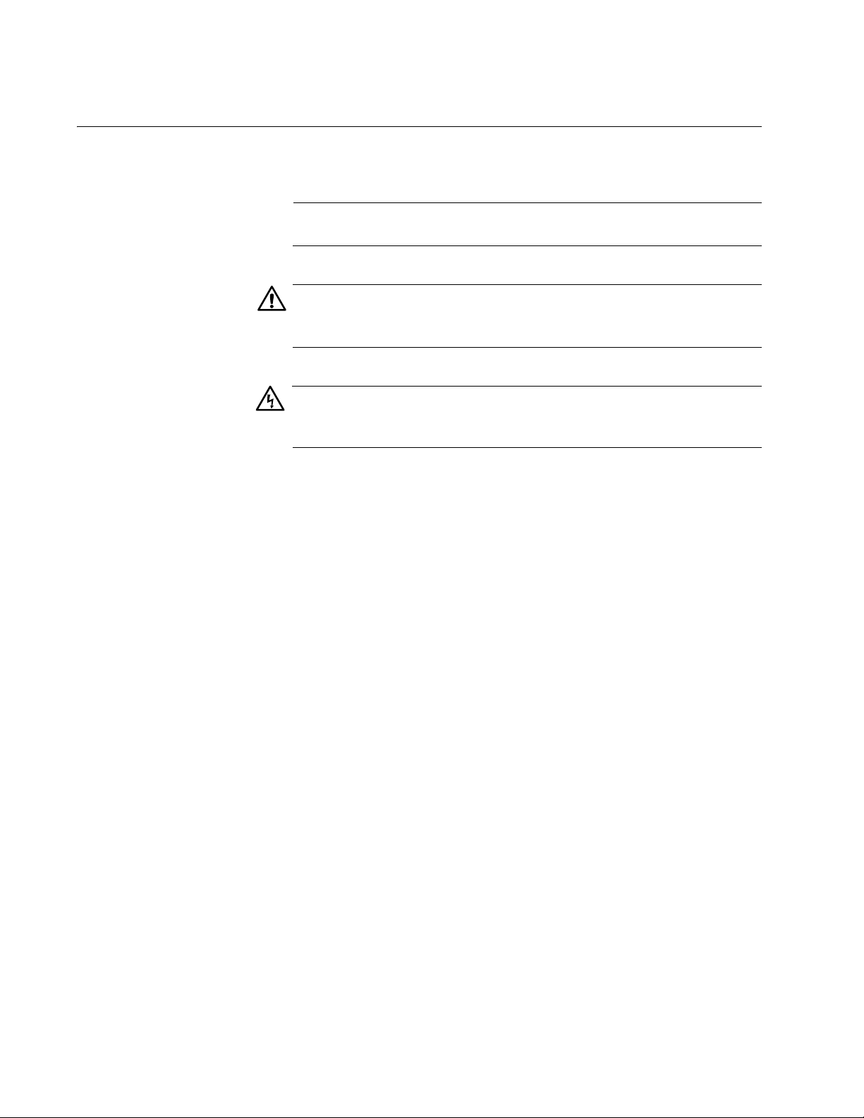
Commands that configure or display the parameters on a media converter
module must include a chassis ID number. This parameter identifies the
chassis with the media converter module. For example, to configure a port
on a media converter module with the SYSTEM SET PORT command,
you must include in the command the chassis ID of the unit with the
module. See Figure 1.
Chassis ID Jumper
AT-MCF2000M
ST
A
C
K
L
IN
K
AC
T
M
A
N
AG
E
M
1
E
000
N
T
L
INK
AC
T10
/10
T
E
0 L
R
M
IN
IN
KAC
A
L
T
F
P
D
O
X
R
T
H
A
D
C
X
T
IV
IT
C
Y
O
L
1
0
/1
0
0
/
1
0
0
0
B
A
S
E
-T
R
E
S
E
T
BOO
T
R
D
Y
FA
U
L
RS-232
T
SD
M
R
D
A
Y
S
T
E
R
B
USY
POW
E
R
18
Chassis ID 0
Chassis ID 31
(Default)
Figure 1. Chassis ID Jumper on the AT-MCF2000M Management Module
Page 19

AT-S85 and AT-S97 Management Software Command Line Interface User’s Guide
The ID number for a chassis is set with a jumper on the management
module, shown in Figure 1 on page 18. The chassis ID number for a
management module is either 0 or 31. The default setting is 0.
Within a stack, you assign the management module on the master unit
with a chassis ID of 0. You assign all of the AT-MCF2000S Stacking
modules on the slave chassis with a chassis ID of 1 through 30. For more
information about stacking, see Chapter 2, “Stacking” on page 35.
To view the ID number of a chassis, issue this command:
system show cluster
For further information, see “Displaying the Chassis Modules” on page 28
or “SYSTEM SHOW CLUSTER” on page 99.
19
Page 20
Chapter 1: Starting a Command Line Management Session
Starting a Local Management Session
Note
Local management sessions do not require an IP configuration on
the AT-MCF2000M Management Module.
To start a local management session on the chassis, perform the following
procedure:
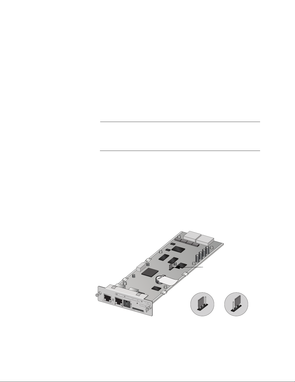
1. Connect the DIN-8 connector on the RS-232 Serial Management
Cable included with the AT-MCF2000M Management Module to the
RS-232 Terminal port on the module, as shown in Figure 2.
AT-MC F2000M
STACK M
ID
LINK ACT
A
N
AGE
M
1000 LINK
EN
T
ACT 10/100 LINK ACT
TERMIN
AL
0
3
1
10/100/1000BASE-T
RS-232
FDX
P
ORT
HDX
A
C
TIV
IT
COL
Y
RESET
SD
R
DY BUSY
AT-MCF2KFAN
BOOT
RDY
FAULT
M
A
S
T
E
R
1261
STATUS
N
O
R
M
A
L
F
A
U
L
T
POW
E
R
Figure 2. Connecting the RS-232 Serial Management Cable to the RS-232
Terminal Port
2. Connect the other end of the cable to an RS-232 port on a terminal or
PC with a terminal emulator program.
3. Configure the terminal or terminal emulation program as follows:
Baud rate: 115,200 bps (The RS-232 Terminal port has a baud
rate range of 9600 to 115,200 bps. The default is 115,200 bps. To
adjust the baud rate, refer to “SYSTEM SET ASYNCHRONOUS”
on page 58.)
Data bits: 8
Parity: None
Stop bits: 1
Flow control: None
Note
The port settings are for a DEC VT100 or ANSI terminal, or an
equivalent terminal emulator program.
20
Page 21

AT-S85 and AT-S97 Management Software Command Line Interface User’s Guide
Note
The prompt “Hit any key to stop autoboot,” displayed on the console
when the management module is reset or power cycled, is for
manufacturing purposes only and should be ignored. If you
inadvertently display the manufacturing prompt (=>), type “bootapp”
to launch the management software on the management module.
4. Press Enter.
You are prompted for a user name and password.
5. Enter a user name and password. The management module has a
predefined manager account with the privilege level of administrator.
The account provides unlimited access to all the parameters on the
management and media converter modules. To log in using this
account, enter “manager” as the user name. The default password for
the account is “friend.” The user name and password are case
sensitive.
After you have logged in, the management software displays the
command line interface, shown in Figure 3.
Allied Telesis Media Converter- Version 2.0.0
#
<No System Name>
Figure 3. Command Line Interface Prompt
The symbol in the command line prompt reflects the access level of
your manager account. The predefined manager account has the
pound symbol (#) prompt. A read-write or read-only account has a
dollar symbol ($) prompt. For information on the three manager
privilege levels of the AT-S97 Management Software, refer to
“Manager Privilege Levels” on page 17. For instructions on how to
change a password or create additional manager accounts, refer to
Chapter 14, “Manager Account Commands” on page 215.
You can now begin to manage the chassis. For suggestions on what to
configure during the initial configuration, refer to “What to Configure
First” on page 28.
21
Page 22

Chapter 1: Starting a Command Line Management Session
Starting a Remote Telnet or Secure Shell Management Session
Review the following guidelines before starting a remote Telnet or Secure
Shell (SSH) management session:
The AT-MCF2000M Management Module must have an IP
configuration. For instructions, refer to Chapter 4, “IP Configuration
Commands” on page 47.
The 10/100/1000Base-T Management port on the management
module must be connected to a device on your network, such as a
Fast Ethernet or Gigabit Ethernet switch. Remote management
sessions are conducted through this port.
The Telnet server or SSH server on the management module must be
enabled. For instructions, refer to Chapter 11, “Telnet Server
Commands” on page 195 or Chapter 13, “Secure Shell Server (SSH)
Commands” on page 209.
The remote Telnet or SSH client must be a member of the same
network as the management module or have access to it through
Layer 3 routing devices.
If the management module and the remote Telnet or SSH client reside
on different networks, the IP configuration on the module must include
a default gateway address specifying the IP address of the routing
interface of the first hop to reaching the remote client. For instructions,
refer to Chapter 4, “IP Configuration Commands” on page 47.
The management module can support 20 Telnet and 20 SSH
management sessions, simultaneously.
To start a remote Telnet or SSH management session, perform the
following procedure:
1. Enter the IP address of the AT-MCF2000M Management Module in the
Telnet or SSH client on the remote workstation.
The management software prompts you for a user name and
password.
2. Enter a user name and password. The management module has a
predefined manager account with the privilege level of administrator
and unlimited access to all of the parameters on the management and
media converter modules. To log in using this account, enter
“manager” as the user name. The default password for the account is
“friend.” The user name and password are case sensitive.
22
The local management session starts and the command line interface
prompt is displayed, as shown in Figure 3 on page 21.
Page 23

AT-S85 and AT-S97 Management Software Command Line Interface User’s Guide
For information on the three manager privilege levels of the AT-S97
Management Software, refer to “Manager Privilege Levels” on
page 17. For instructions on how to change a password or create
additional manager accounts, refer to Chapter 14, “Manager Account
Commands” on page 215.
The section “What to Configure First” on page 28 has suggestions on
what you should configure during the initial management session of
the chassis.
23
Page 24

Chapter 1: Starting a Command Line Management Session
SNMP Management Session
You can also manage the AT-MCF2000 chassis remotely using an Simple
Network Management Protocol (SNMP) management program such as
HP Openview. This method, however, does not use the management
interface.
To manage the chassis from a management workstation using an SNMP
management program, you need to load the Management Information
Base (MIB) file, atMCF2000.mib, that was included with the AT-S85 and
AT-S97 software onto the management workstation. (The MIB file is
available from the Allied Telesis web site.)
This requires that you use a MIB compiler to compile the file. A familiarity
with MIB objects is necessary for this type of management. To load the
MIB file onto a management workstation, follow the instructions included
with your MIB compiler. For instructions on how to compile the MIB file
with your SNMP program, refer to your SNMP management
documentation.
To establish a SNMP management session for a unit that is remotely
managed, the chassis must have a management card and an IP address.
Before performing the SNMP management session, note the followings:
The 10/100Base-TX port on the management card must be connected
to the network.
The remote management workstation must reach the chassis through
the subnet of the management card.
24
Page 25

Quitting a Management Session
To quit a management session, enter Exit at the command prompt. You
should always exit from a management session when you are finished
managing a media converter. This can prevent unauthorized individuals
from making changes to a unit’s configuration if you leave your
management station unattended. For information about how to use the
console timer to automatically disconnect a management session, refer to
“SYSTEM SET CONSOLE” on page 61.
Note
Failure to properly exit from a management session may block future
management sessions until the console timer times out. For
information on the console timer, refer to “SYSTEM SET
CONSOLE” on page 61.
AT-S85 and AT-S97 Management Software Command Line Interface User’s Guide
25
Page 26

Chapter 1: Starting a Command Line Management Session
Command Line Interface Features
The command line interface supports the following features:
Command history - You can scroll through a history of your commands
with the up and down arrow keys.
Context-specific help - Typing a question mark against the command
line prompt displays a list of the command keywords. Additionally,
typing a question mark when entering a command displays a list of
legal parameters.
Keyword abbreviations - Keywords can be recognized by typing an
unambiguous prefix, for example, “sy” for “system.”
Tab key - Pressing the Tab key fills in the rest of the keyword. For
example, typing “mo” and pressing the Tab key enters “module.”
26
Page 27

Command Formatting
The following formatting conventions are used in this manual:
screen text font - This font illustrates the format of a command and
command examples.
screen text font
to enter.
[ ] - Brackets indicate optional parameters.
| - Vertical line separates parameter options for you to choose from.
AT-S85 and AT-S97 Management Software Command Line Interface User’s Guide
- Italicized screen text indicates a variable for you
27
Page 28

Chapter 1: Starting a Command Line Management Session
What to Configure First
This section has a few suggestions on what to configure when you are
managing the chassis for the first time. The initial management session
must be a local session. For instructions on how to start a local
management session, refer to “Starting a Local Management Session” on
page 20.
Note
Although the management module comes with the default IP
address of 10.0.0.1 and subnet mask of 255.255.252.0, the initial
configuration must be a local session because the module’s Telnet
and SSH servers are initially disabled.
Displaying the
Chassis Modules
Chassis Chassis Chassis MAC Master
ID Name Type Address Chassis
-----------------------------------------------------------------0 AT-MCF2000 11:22:33:44:55:55 Yes
Slot ID Module Name Module Type Software Version
-----------------------------------------------------------M AT-MCF2000M v2.0.0
1 AT-MCF2012LC v2.0.0
2 AT-MCF2012LC v2.0.0
After logging on, enter this command:
system show cluster
The command displays the management and media converter modules in
the chassis. You can use this information to verify the modules in the unit.
An example is shown in Figure 4.
Management and media converter module information
Chassis information
28
Figure 4. Displaying the Chassis Modules
For information about this command, refer to “SYSTEM SHOW
CLUSTER” on page 99.
Page 29

AT-S85 and AT-S97 Management Software Command Line Interface User’s Guide
Note
To avoid possible compatibility problems between the management
module and the media converter modules, Allied Telesis
recommends that all modules in a chassis or stack use the same
version of the AT-S85 and AT-S97 Management Software. If the
modules shown in the SYSTEM SHOW CLUSTER command have
different versions, you should upgrade the operating software on the
modules. For instructions, Chapter 10, “File System Commands” on
page 165.
Changing the
Manager
Password
Creating a
Master
Configuration
File
Because the default password for the predefined manager account is
included in this document, which is posted on our web site where anyone
with a web browser can see it, you should change the password as part of
the initial configuration to protect the unit from unauthorized access. To
change the password, enter this command:
user set username=manager password
You are prompted to change the password. A password can be up to 16
alphanumeric characters and is case sensitive. Special characters,
including spaces, question marks, and quotation marks, are permitted.
You are prompted twice to verify the new password.
For information on how to create additional manager accounts, refer to
Chapter 14, “Manager Account Commands” on page 215.
This step creates a master configuration file in the file system on the
management module. The module uses the file to store your parameter
changes. Without the file, the module cannot save your parameter settings
and you will have to reenter them if you reset or power cycle the chassis.
This task has two steps. The first step creates the file with the CONFIG
SAVE FILESYSTEM command. The format of the command is:
config save filesystem=system://
The chassis variable is the ID number of the chassis. A chassis with a
management module installed has a chassis ID of 0 or 31. This value is
set with a jumper on the circuit board of the module. The chassis ID of a
chassis with a stacking module is 1 through 30. The value is also set
manually on the stacking module.To view this number, use the SYSTEM
SHOW CLUSTER command.
The slot variable specifies the chassis slot that has the management
module, signified by the letter “m.”
chassis/slot/filename
.cfg
29
Page 30

Chapter 1: Starting a Command Line Management Session
And, finally, filename.cfg is the filename for the new master configuration
file. The name can be up to 15 alphanumeric characters, not including the
extension. Spaces are allowed, but a name with spaces must be enclosed
in double quotes.
This example of the command creates the new master configuration file
“mcf_chassis0.cfg” on a management module in a chassis with an ID
number of 0:
config save filesystem=system://0/m/mcf_chassis0.cfg
For further information on this command, refer to “CONFIG SAVE
FILESYSTEM” on page 158.
Now that you have created the master configuration file, you are ready to
perform the second step and designate it as the module’s active master
configuration file. This directs the management module to the appropriate
master configuration file when saving your changes. (In some cases, the
management module might have more than one master configuration file,
such as a history of past configuration files, but only one of the files can be
active at a time.) The command for designating the active master
configuration file is the CONFIG SET command. Here is the format:
config set filesystem=system://
chassis/slot/filename
.cfg
The definitions of the variables in this command are the same as in the
CONFIG SAVE FILESYSTEM command. Here is an example of the
command that designates the “mcf_chassis1.cfg” file created in the
previous command as the management module’s active configuration file:
config set filesystem=system://0/m/mcf_chassis1.cfg
Configuration filenames in both the CONFIG SAVE FILESYSTEM and
CONFIG SET commands are case sensitive. For more information on this
command, refer to “CONFIG SET” on page 160.
This completes the procedure for creating and designating a new active
master configuration file on the management module. The management
module can now save your parameter changes when you issue the
CONFIG SAVE command.
30
Page 31

AT-S85 and AT-S97 Management Software Command Line Interface User’s Guide
Assigning an IP
Configuration
Will you be remotely managing the chassis with the Telnet or Secure Shell
(SSH) application protocol? Or, will the management module be
performing any of the following management tasks?
Uploading or downloading files to its file system from a TFTP server.
Setting the date and time from a Network Time Protocol (NTP) server
Sending events to a syslog server
Sending or receiving TCP/IP ping requests from another network
device
Managing the device with SNMP
If so, the module must have an IP configuration with an IP address, subnet
mask, and possibly a default gateway address on the management
module. You can assign the IP configuration manually or activate the
DHCP and BOOTP clients and have a DHCP or BOOTP server on your
network supply the configuration, automatically. (If you choose the latter
and want to know the MAC address of the chassis, refer to “Displaying the
Chassis Modules” on page 28 or “SYSTEM SHOW CLUSTER” on
page 99.)
The command for manually assigning an IP configuration to the
management module is:
ip set ip-address=
default-gateway=
ipaddress
ipaddress
subnetmask=
mask
In this example, the management module is assigned the IP address
149.112.44.22, the subnet mask 255.255.255.0, and the default gateway
149.112.44.242:
ip set ip-address=149.112.44.22 subnetmask=255.255.255.0
default-gateway=149.112.44.242
For more information on this command, refer to “IP SET” on page 52.
If you want the management module to obtain its IP configuration from a
DHCP or BOOTP server on your network, activate the DHCP and BOOTP
clients with this command:
ip dhcp enable
For more information on this commands, refer to “IP DHCP ENABLE” on
page 51.
Note
Be sure to connect the 10/100/1000Base-T Management port on the
management module to your network before assigning an IP
configuration to the module. The management module
communicates with your network through this port.
31
Page 32

Chapter 1: Starting a Command Line Management Session
Setting the Date
and Time
The management module adds the date and time to the event messages
logged in its event log. You can set the date and time manually or with a
Network Time Protocol (NTP) server on your network or the Internet. The
command for manually setting the date and time is:
system set clock date=mm/dd/
This example sets the date to April 11, 2007 and the time to 4:34 pm:
system set clock date=4/11/2007 time=16:34:0
If the date and time of the management module will be supplied by an NTP
server, you must specify the IP address of the server and activate the NTP
client. This command specifies the server’s IP address:
ntp set server=
The ipaddress variable is the IP address of the NTP server. This example
specifies the IP address of the NTP server as 149.122.55.77:
ntp set server=149.122.55.77
After specifying the server’s IP address, activate the NTP client with this
command:
ipaddress
yyyy
time=
hh:mm:ss
Enabling the
Telnet or Secure
Shell Server
ntp enable
Note
Review the section “NTP Client Guidelines” on page 114 before
activating the client.
Will you be managing the chassis over the network from a remote
workstation with the Telnet or SSH application protocol? If so, you must
activate the appropriate server on the management module. To enable the
Telnet server, enter this command:
telnet enable
To enable the SSH server, enter this command:
ssh enable
For information of the Telnet server commands, refer to Chapter 11,
“Telnet Server Commands” on page 195. For information on the SSH
commands, refer to Chapter 13, “Secure Shell Server (SSH) Commands”
on page 209
32
Page 33

AT-S85 and AT-S97 Management Software Command Line Interface User’s Guide
Naming a Chassis Naming a chassis makes it easier for you to identify it in the management
software and may help you avoid the common mistake of performing a
command or procedure on the wrong device. The command is SYSTEM
SET CHASSIS and the format is:
Saving Your
Changes
system set chassis id=
The chassis variable is the ID number of the chassis. If you have a
management module installed in the chassis, the chassis id is either 0 (the
default) or 31. If you have a stacking module installed in your chassis, you
can assign a range of 1 to 30 as the chassis ID. To view this number, use
the SYSTEM SHOW CLUSTER command.
The name variable specifies a name of up to 20 alphanumeric characters
for the chassis. Spaces are allowed, but a name with spaces must be
enclosed in double quotes (“ “).
This example assigns the name “Region 1 Traffic” to a chassis with an ID
number of 1:
system set chassis id=1 name=”Region 1 Traffic”
For more information on the SYSTEM SET CHASSIS command, refer to
“SYSTEM SET CHASSIS” on page 59.
This completes the initial configuration of the chassis. To update the
configuration files on the modules with your changes, enter this command:
config save
chassis
name=
name
For more information on the command, refer to “Saving Your Configuration
Changes” on page 17 or Chapter 9, “Configuration File Commands” on
page 141.
Note
If you do not issue the CONFIG SAVE command and later reset or
power cycle the device, your changes will be discarded.
Note
To make identifying the chassis easier, Allied Telesis recommends
attaching a label to the front panel of the unit with its chassis ID
number, name, and MAC address. To view this information, use the
SYSTEM SHOW CLUSTER command.
33
Page 34

Chapter 1: Starting a Command Line Management Session
34
Page 35

Chapter 2
Stacking
This chapter describes how to set up an AT-MCF2000 stack. It contains
the following sections:
“Overview” on page 36
“Required Modules” on page 37
“AT-S85 and AT-S97 Management Software Versions” on page 38
“Setting Up Stacking” on page 39
35
Page 36

Chapter 2: Stacking
Overview
The AT-MCF2000 chassis and the media converter modules interconnect
Ethernet networking devices over large distances by transferring Ethernet
packets between twisted pair and fiber optic cables. The chassis can
accommodate two multi-channel media converter modules as well as the
optional AT-MCF2000M Management Module for either local (out-ofband) or remote (in-band) network management of the ports on the media
converter modules.
You can use the AT-MCF2000 chassis as a standalone unit or you can
connect additional units to create a stack. In an AT-MCF2000 stack, there
is one master chassis and one to eight member chassis. With the
management module installed in the master chassis, you can stack up to
seven additional chassis that have the AT-MCF2000S Stacking Module
installed. A stack merges and synchronizes the network operations of two
or more AT-MCF2000 chassis to form a single, logical unit where
management functions span all of the ports in the stack.
Stacking
Guidelines
You can manage the AT-MCF2000 stack locally through the Terminal Port
on the master unit of the stack or remotely using a Telnet or Secure Shell
Client.
See the list of stacking guidelines below:
The chassis are managed as a unit.
The chassis are linked together with the stacking module.
You can mix and match media converter modules within the stack.
There is a limit of eight chassis (one master chassis and seven
member chassis) and 16 media converter modules installed in one
stack.
To create a stack of media converters, daisy-chain the units with the
Stack ports. The Stack port on the management module must be
connected to Stack 1 or Stack 2 port on the stacking module in the next
chassis. The remaining Stack port on the stacking module must be
connected to the Stack 1 or Stack 2 port on the next chassis and so.
For more information about cabling, see the AT-MCF2000S Stacking
Module Installation Guide.
36
Page 37

Required Modules
AT-S85 and AT-S97 Management Software Command Line Interface User’s Guide
To be part of a stack, the master chassis in the stack must have the
AT-MCF2000M Management Module installed. See Figure 5. In addition,
each member chassis in the stack must have the AT-MCF2000S Stacking
Module installed. See Figure 6.
Both modules are installed in the management module slot on the front
panel of the chassis. For installation instructions, see the AT-MCF2000M
Management Module Installation Guide and the AT-MCF2000S Stacking
Module Installation Guide.
AT-M
CF2
000M
S
T
A
C
K
L
IN
K
AC
T
M
A
N
AG
E
M
100
E
N
0 LIN
T
K
AC
T 10/1
T
0
E
0
R
L
M
IN
IN
KAC
A
L
T
F
P
D
O
X
R
T
H
A
D
C
X
T
IV
IT
C
Y
O
L
1
0
/1
0
0
/
1
00
0
B
A
S
E
-T
R
E
S
E
T
BOO
T
R
D
Y
FA
U
L
RS-232
T
SD
R
D
Y
B
USY
1198a
M
A
S
T
E
R
POW
E
R
Figure 5. AT-MCF2000M Management Module
A
T-MCF2000S
S
T
A
CK 1
LIN
K
PORT ACTIVITY
A
CT
S
T
A
CK 2
CHASSIS
ID
1264
Figure 6. AT-MCF2000S Stacking Module
37
Page 38

Chapter 2: Stacking
AT-S85 and AT-S97 Management Software Versions
To create a stack, the management, stacking, and media converter
modules require Version 1.4.0 or later of the AT-S97 and AT-S85
Management Software. Earlier versions of the management software do
not support this feature.
A stack supports all of the features described in “Command Line Interface
Features” on page 26.
38
Page 39

Setting Up Stacking
When creating a stack, you need to designate a master chassis and from
one to seven member chassis. The management module has a chassis id
of 0 which automatically designates this chassis as the master chassis of
the stack by default. For instructions about how to move the jumper, see
“Setting Chassis ID Numbers” on page 18.
To designate a member unit, set the chassis ID of each stacking module to
1 through 30 by moving DIP switches on the module. You must assign a
unique chassis ID to each member chassis.
To view the chassis IDs of the master and member chassis, use the
SHOW CLUSTER command. See “SYSTEM SHOW CLUSTER” on
page 99.
AT-S85 and AT-S97 Management Software Command Line Interface User’s Guide
39
Page 40

Chapter 2: Stacking
40
Page 41

Chapter 3
Basic Commands
This chapter describes basic AT-S97 software commands. It contains the
following commands:
“Question Mark ‘?’ Key” on page 42
“CLEAR” on page 43
“EXIT” on page 44
“HELP” on page 45
“PING” on page 46
41
Page 42

Chapter 3: Basic Commands
Question Mark ‘?’ Key
Syntax
?
Parameters
None.
Privilege Levels
Administrator, read-write, and read-only.
Description
Entering a question mark at the command line prompt displays a list and a
brief description of the command line keywords. Entering a question mark
after a keyword displays the available keyword parameters. Additionally,
entering a question mark after a parameter displays the parameter’s class
(that is, integer, string, etc.).
Examples
This command lists the command keywords:
?
This command displays the available parameters for the BOOT keyword:
boot ?
This command displays the class of the value for the SET parameter in the
CONFIG command:
config set?
42
Page 43

CLEAR
AT-S85 and AT-S97 Management Software Command Line Interface User’s Guide
Syntax
clear
Parameters
None.
Privilege Levels
Administrator, read-write, and read-only.
Description
This command clears the screen.
Example
clear
43
Page 44

Chapter 3: Basic Commands
EXIT
Syntax
exit
Parameters
None.
Privilege Levels
Administrator, read-write, and read-only.
Description
This command ends a management session.
Example
exit
44
Page 45

HELP
AT-S85 and AT-S97 Management Software Command Line Interface User’s Guide
Syntax
help
Parameters
None.
Privilege Levels
Administrator, read-write, and read-only.
Description
This command displays information about how you can use the “?” and tab
keys to simplify the entry of commands.
Example
help
45
Page 46

Chapter 3: Basic Commands
PING
Syntax
ping
ipaddress
Parameter
ipaddress Specifies the IP address of the device to ping.
Privilege Levels
Administrator and read-write.
Description
This command tests for a network connection between the management
module and a remote device by sending three TCP/IP ping requests. The
results of the requests are displayed on your workstation. The following
guidelines apply to this command:
The management module must have an IP configuration. For
instructions, see Chapter 4, “IP Configuration Commands” on page 47.
The 10/100/1000Base-T Management port on the management
module must be connected to your network. The ping requests are
transmitted from this port.
The management module must be a member of the same subnet as
the remote device or have access to the device’s subnet through
routers or other Layer 3 routing devices.
If the management module and the remote device are members of
different networks, the IP configuration on the module must include a
default gateway address specifying the IP address of the routing
interface of the first hop to reaching the device. For instructions, refer
to Chapter 4, “IP Configuration Commands” on page 47.
Example
This command sends three ping requests from the management module
to the remote device with the IP address 149.12.55.77:
ping 149.12.55.77
46
Page 47

Chapter 4
IP Configuration Commands
This chapter describes how to assign an IP address to the AT-MCF2000M
Management Module. This chapter contains the following sections:
“Overview” on page 48
“IP DHCP DISABLE” on page 50
“IP DHCP ENABLE” on page 51
“IP SET” on page 52
“IP SHOW” on page 54
Note
Remember to save your parameters changes in the active master
configuration file with the CONFIG SAVE command. For information,
refer to “Saving Your Configuration Changes” on page 17 or Chapter
9, “Configuration File Commands” on page 141.
47
Page 48

Chapter 4: IP Configuration Commands
Overview
The IP commands assign an IP configuration to the AT-MCF2000M
Management Module consisting of an IP address, subnet mask, and
default gateway address. An IP configuration is required if the module
performs any of the following functions:
Remote management using the Telnet and Secure Shell (SSH)
application protocols.
Managing the media converter with the Simple Network Management
Protocol (SNMP)
Uploading or downloading files to its file system from a TFTP server
Downloading files to its file system from an Xmodem server
Setting the date and time from a Network Time Protocol (NTP) server
Sending events to a syslog server
Sending or receiving TCP/IP ping requests from network devices
The IP configuration must include a default gateway address if the
management module will communicate with a network device on a
different subnet or network than itself. The address, which must be a
member of the same network as the management module, defines the
routing interface of the first hop to reaching the remote device. For
example, the module must have a default gateway address if:
You will be managing the unit remotely from a Telnet client on a
different network from the management module
If the unit will set its date and time from an NTP server on another
network.
You can assign the IP configuration manually with the IP SET command or
from a DHCP or BOOTP server on your network by activating the DHCP
and BOOTP clients on the module with the IP DHCP ENABLE command.
If you assign the management module an IP configuration, you must
connect the 10/100/1000Base-T Management port on the module to a
network device, such as a Fast Ethernet or Gigabit Ethernet Switch. The
AT-MCF2000M Management Module can only communicate with the
network through the Management port. It cannot communicate through the
ports on the media converter modules in the chassis.
48
Note
The forwarding of network traffic by the ports and channels on a
media converter module is independent of the management module
and does not require an IP configuration.
Page 49

AT-S85 and AT-S97 Management Software Command Line Interface User’s Guide
Command
Summary
Table 1 summarizes the IP configuration commands.
Table 1. IP Configuration Commands
Command Description
IP DHCP DISABLE on
page 50
IP DHCP ENABLE on page 51 Activates the DHCP and BOOTP
IP SET on page 52 Manually sets the IP configuration.
IP SHOW on page 54 Displays the IP address, subnet
Deactivates the DHCP and
BOOTP clients on the
management module.
clients on the management
module.
mask, and default gateway of the
management module.
49
Page 50

Chapter 4: IP Configuration Commands
IP DHCP DISABLE
Syntax
ip dhcp disable
Parameters
None.
Privilege Levels
Administrator and read-write.
Description
This command deactivates the DHCP and BOOTP clients on the
management module. When the clients are deactivated, the module’s IP
configuration immediately returns to the default values. The default setting
for the DHCP and BOOTP clients is disabled.
To manually assign an IP configuration to the management module, refer
to “IP SET” on page 52.
Example
ip dhcp disable
50
Page 51

IP DHCP ENABLE
Syntax
ip dhcp enable
Parameters
None.
Privilege Levels
Administrator and read-write.
Description
This command activates the management module’s DHCP and BOOTP
clients for setting the module’s IP configuration from a DHCP or BOOTP
server on your network. Refer to “Overview” on page 48 for background
information on when to assign an IP configuration to the management
module.
AT-S85 and AT-S97 Management Software Command Line Interface User’s Guide
The management module queries first for a DHCP server. If it receives a
response, it applies the IP configuration from the server to its IP
parameters, and stops querying the network. If there is no response after
seven attempts, the management module queries for a BOOTP server. If
there is again no response, the management module stops its query
efforts.
The default setting for the DHCP and BOOTP clients is disabled.
Note
If the module already has a manually assigned IP configuration, it
will be overwritten by the values from the DHCP or BOOTP server.
Communications between the management module and the DHCP or
BOOTP server are conducted through the module’s 10/100/1000Base-T
Management port. Consequently, this port must be connected to a
network device, such as a Fast Ethernet or Gigabit Ethernet switch. The
management module cannot communicate with a server through the ports
on the media converter modules in the chassis.
Example
ip dhcp enable
51
Page 52

Chapter 4: IP Configuration Commands
IP SET
Syntax
ip set ip-address=
default-gateway=
ipaddress
ipaddress
subnetmask=
mask
Parameters
ip-address Specifies an IP address for the AT-MCF2000M
Management Module. The default value is 10.0.0.1.
subnetmask Specifies a subnet mask for the management module’s IP
address. The mask can be of variable length. The default
value is 255.255.252.0.
default-gateway
Specifies a default gateway for the management module.
The default gateway must be a member of the same subnet
as the module’s IP address. The default value is 0.0.0.0.
Privilege Levels
Administrator and read-write.
Description
This command manually assigns an IP address, subnet mask, and default
gateway address to the AT-MCF2000M Management Module. For
information on when to assign an IP configuration to the module, refer to
“Overview” on page 48.
52
Note
You cannot assign an IP configuration to the management module if
the DHCP and BOOTP clients are active. You must first disable the
clients with the IP DHCP DISABLE command. For information, refer
to “IP DHCP DISABLE” on page 50. To determine the status of the
clients, refer to “IP SHOW” on page 54.
Examples
This command assigns the IP address 149.22.67.8, subnet mask
255.255.255.224, and default gateway 149.22.67.247 to the
AT-MCF2000M Management Module:
ip set ip-address=149.22.67.8 subnetmask=255.255.255.224
default-gateway=149.22.67.247
Page 53

AT-S85 and AT-S97 Management Software Command Line Interface User’s Guide
This command assigns the default gateway address 149.44.55.22 to the
management module:
ip set default-gateway=149.44.55.22
This command removes the current IP address and subnet mask values
without assigning new values:
ip set ip-address=0.0.0.0 subnetmask=0.0.0.0
53
Page 54

Chapter 4: IP Configuration Commands
IP SHOW
Syntax
ip show
Parameters
None.
Privilege Levels
Administrator, read-write, and read-only.
Description
This command displays the management module’s IP address, subnet
mask, and default gateway address, as shown in Figure 7.
IP Information:
IP Address........... 149.25.42.11
Subnet Mask.......... 255.255.255.0
Gateway.............. 149.25.42.27
DHCP................. Disable
Figure 7. IP SHOW Command
For further information, refer to the following sections:
“Overview” on page 48 for background information on when to assign
an IP configuration to the management module.
“IP SET” on page 52 for instructions on how to manually assign these
values.
“IP DHCP DISABLE” on page 50 for instructions on how to activate the
DHCP and BOOTP clients.
Example
ip show
54
Page 55

Chapter 5
General System Commands
This chapter describes the commands that control and display basic
parameters on the management module. This chapter contains the
following sections:
“Overview” on page 56
“SYSTEM SET ASYNCHRONOUS” on page 58
“SYSTEM SET CHASSIS” on page 59
“SYSTEM SET CLOCK” on page 60
“SYSTEM SET CONSOLE” on page 61
“SYSTEM SET CONTACT” on page 62
“SYSTEM SET HOSTNAME” on page 63
“SYSTEM SET LOCATION” on page 64
“SYSTEM SHOW ASYNCHRONOUS” on page 65
“SYSTEM SHOW CLOCK” on page 66
“SYSTEM SHOW CONSOLE” on page 67
“SYSTEM SHOW INFO” on page 68
Note
Remember to save your parameters changes in the active master
configuration file with the CONFIG SAVE command. For information,
refer to “Saving Your Configuration Changes” on page 17 or Chapter
9, “Configuration File Commands” on page 141.
55
Page 56

Chapter 5: General System Commands
Overview
The system commands are divided into two groups in this manual. The
first set of commands, described in this chapter, control and display the
basic parameters on the management module, such as the chassis’ name
and the date and time.
The commands in the second group control the individual ports and
channels on the media converter modules. These functions include setting
port parameters, such as speed and duplex mode, resetting media
converter modules, and displaying status information on the modules in a
chassis or stack. The system commands in this group are described in
Chapter 6, “Port and Module Commands” on page 69.
Command
Summary
Table 2 summarizes the general system commands described in this
chapter.
Table 2. General System Configuration Commands
Command Description
“SYSTEM SET
ASYNCHRONOUS” on
page 58
“SYSTEM SET CHASSIS” on
page 59
“SYSTEM SET CLOCK” on
page 60
“SYSTEM SET CONSOLE” on
page 61
“SYSTEM SET CONTACT” on
page 62
Sets the baud rate of the RS-232
Terminal port on the management
module.
Assigns a name to a chassis.
Manually sets the date and time.
Sets the console timeout
parameter for ending inactive
management sessions.
Identifies the network
administrator responsible for
maintaining the chassis or stack.
56
“SYSTEM SET HOSTNAME”
on page 63
“SYSTEM SET LOCATION” on
page 64
“SYSTEM SHOW
ASYNCHRONOUS” on
page 65
“SYSTEM SHOW CLOCK” on
page 66
Specifies a name for the stack.
Specifies the location of the stack.
Displays the baud rate of the RS232 Terminal port on the
management module.
Displays the date and time.
Page 57

AT-S85 and AT-S97 Management Software Command Line Interface User’s Guide
Table 2. General System Configuration Commands (Continued)
Command Description
“SYSTEM SHOW CONSOLE”
on page 67
“SYSTEM SHOW INFO” on
page 68
Displays the console timeout
parameter.
Displays the stack’s name, the
name of the network administrator
responsible for managing the
units, and the location of the stack.
57
Page 58

Chapter 5: General System Commands
SYSTEM SET ASYNCHRONOUS
Syntax
system set asynchronous baudrate=2400|4800|9600|19200|115200
Parameters
baudrate Sets the baud rate of the RS-232 Terminal port on the
AT-MCF2000M Management Module. The default is
115,200 bits per second (bps).
Privilege Levels
Administrator and read-write.
Description
This command sets the baud rate of the RS-232 Terminal port on the
AT-MCF2000M Management Module. This port is used for local
management of the chassis. To view the port’s current baud rate setting,
refer to “SYSTEM SHOW ASYNCHRONOUS” on page 65.
Note
Changing the baud rate of the RS-232 Terminal port on the
management module during a local management session ends the
session. To resume managing the module, change the speed of the
terminal or the terminal emulator program to the new speed of the
RS-232 Terminal port.
The other settings of the RS-232 Terminal port listed here are not
adjustable:
Data bits: 8
Parity: None
Stop bits: 1
Flow control: None
Example
This command sets the baud rate of the RS-232 Terminal port to 2,400
bps:
system set asynchronous baudrate=2400
58
Page 59

SYSTEM SET CHASSIS
Syntax
AT-S85 and AT-S97 Management Software Command Line Interface User’s Guide
system set chassis id=
chassis
name=
name
Parameters
id Identifies the ID number of the chassis which depends on
the module installed in the management slot of the chassis.
On a management module, the chassis ID number is 0 or
31. On a stacking module, the chassis ID can be from 1 to
30. To view the ID number of a unit, use the SYSTEM
SHOW CLUSTER command. For instructions, refer to
“SYSTEM SHOW CLUSTER” on page 99.
name Specifies a name of up to 20 alphanumeric characters for
the chassis. Spaces are permitted, but a name with spaces
must be enclosed in double quotes (“ “). To remove the
current value without specifying a new value, enter “none”.
Privilege Levels
Administrator and read-write.
Description
This command assigns a name to a chassis. Names can makes it easier to
identify different devices. This command is different from the SYSTEM
SET HOSTNAME command in that the latter assigns a name to an entire
stack, while this command can assign names to the individual units in a
stack. To view the current name of a chassis, refer to “SYSTEM SHOW
CHASSIS” on page 96 or “SYSTEM SHOW CLUSTER” on page 99.
Examples
This command assigns the name “interconnect51” to a chassis with an ID
number of 0:
system set chassis id=0 name=interconnect51
This command assigns the name “sjc connection” to a chassis with an ID
number of 0:
system set chassis id=0 name="sjc connection"
59
Page 60

Chapter 5: General System Commands
SYSTEM SET CLOCK
Syntax
system set clock date=mm/dd/
yyyy
time=
hh:mm:ss
Parameters
date Specifies the current date in month/day/year format.
time Specifies the current time in 24-hour, hour:minute:second
format. You must include all three parts of the time.
Privilege Levels
Administrator and read-write.
Description
This command manually sets the management module’s date and time
which is added to events messages and SNMP traps. The module is able
to maintain the date and time even when it is reset or power cycled
because it has an onboard battery. To view the current date and time, use
the SYSTEM SHOW CLOCK command. For instructions, see “SYSTEM
SHOW CLOCK” on page 66.
To set the date and time using an Network Time Protocol (NTP) server,
refer to Chapter 7, “Network Time Protocol Commands” on page 113.
60
Note
The date and time from an NTP server overwrites a manually set
date and time.
You do not have to enter the CONFIG SAVE command to save the new
date and time.
Examples
This command sets the date to April 11, 2007 and time to 4:34 pm:
system set clock date=4/11/2007 time=16:34:0
This command sets the time to 7:08 am and 25 seconds:
system set clock time=7:8:25
Page 61

SYSTEM SET CONSOLE
Syntax
AT-S85 and AT-S97 Management Software Command Line Interface User’s Guide
system set console timeout=
value
Parameter
timeout Specifies the console timer in minutes. The range is 0 to 60
minutes. The default is 10 minutes.
Privilege Levels
Administrator and read-write.
Description
This command sets the amount of time (in minutes) the management
software waits before automatically ending an inactive local or remote
management session. This parameter is referred to as the console timer. If
there is no management activity for the duration of the timer, the
management session is automatically logged off. This security feature can
prevent unauthorized individuals from using your management station to
alter the configuration settings of the media converter chassis if you step
away from your system during a management session.
A value of 0 (zero) disables the console timer. Inactive management
sessions are never timed out. This value should be used with caution. If
you disable the console timer, you must remember to log off after every
local and remote management session of the media converter. Or. future
management sessions may be blocked.
To view the current console timer setting, refer to “SYSTEM SHOW
CONSOLE” on page 67.
Note
The console timer is independent of the management module’s date
and time and operates regardless of whether the date and time are
set.
Example
This command sets the console timer to 25 minutes:
system set console timeout=25
61
Page 62

Chapter 5: General System Commands
SYSTEM SET CONTACT
Syntax
system set contact=
contact
Parameter
contact Specifies the name of the network administrator
responsible for maintaining the chassis. The contact can be
up to 25 alphanumeric characters. Spaces are allowed, but
a name with spaces must be enclosed in double quotes
(“ “). To remove the current value without specifying a new
value, enter “none.”
Privilege Levels
Administrator and read-write.
Description
This command sets the name of the network administrator responsible for
managing the chassis. To view this parameter’s current value, refer to
“SYSTEM SHOW INFO” on page 68.
Example
This command sets a chassis’ contact to “Jane Smith:”
system set contact="Jane Smith"
62
Page 63

SYSTEM SET HOSTNAME
Syntax
AT-S85 and AT-S97 Management Software Command Line Interface User’s Guide
system set hostname=
name
Parameter
hostname Specifies a name of up to 25 alphanumeric characters for
the stack. The host name is also used as the command line
prompt. Spaces are permitted, but a host name with spaces
must be enclosed in double quotes (“ “). To remove the
current value without specifying a new value, enter “none.”
Privilege Levels
Administrator and read-write.
Description
This command assigns a name to a stack. The name is displayed at the
top of the console screen during a command line management session.
The first fourteen characters of the host name are also used as the
command line prompt in the management interface. To view the current
value for this parameter, examine the top of the console screen or the
command line prompt. Or, use the SYSTEM SHOW INFO command,
explained in “SYSTEM SHOW INFO” on page 68. To assign individual
names to the chassis in a stack, refer to the SYSTEM SET CHASSIS
command.
Examples
This command sets a stack’s name to “MCF2000 12a traffic:”
system set hostname="MCF2000 12a traffic"
This command removes a stack’s name without assigning a new value:
system set hostname=none
63
Page 64

Chapter 5: General System Commands
SYSTEM SET LOCATION
Syntax
system set location=
location
Parameters
location Specifies a location of up to 25 alphanumeric characters for
the chassis or stack. Spaces are allowed, but a location
with spaces must be enclosed in double quotes (“ “). To
remove the current value without specifying a new value,
enter “none.”
Privilege Levels
Administrator and read-write.
Description
This command sets the location of the chassis or stack. This information
can be helpful in locating the different media converter units in your
network. To view the current value for this parameter, refer to “SYSTEM
SHOW INFO” on page 68.
Examples
This command sets a stack’s location to “Bldg 3, rm 212:”
system set location="Bldg 3, rm 212"
This command removes the current location without assigning a new
value:
system set location=none
64
Page 65

AT-S85 and AT-S97 Management Software Command Line Interface User’s Guide
SYSTEM SHOW ASYNCHRONOUS
Syntax
system show asynchronous
Parameters
None.
Privilege Levels
Administrator, read-write, and read-only.
Description
This command displays the baud rate setting of the management module’s
RS-232 Terminal port, used for local management of the media converter
chassis or stack. An example is shown in Figure 8.
Asynchronous Port (Console) Information:
Baud Rate ............................ 115200
Figure 8. SYSTEM SHOW ASYNCHRONOUS Command
To configure the port’s baud rate, use the SYSTEM SET
ASYNCHRONOUS command. For information, refer to “SYSTEM SET
ASYNCHRONOUS” on page 58.
Example
system show asynchronous
65
Page 66

Chapter 5: General System Commands
SYSTEM SHOW CLOCK
Syntax
system show clock
Parameters
None
Privilege Levels
Administrator, read-write, and read-only
Description
This command displays the current date, time, and Real Time Clock
(RTC) setting of the management module. This information is added to
event messages and SNMP traps. See Figure 9.
System Clock Information
Date ............. 06/04/2007
Time ............. 03:35:25
RTC Source......... none
Figure 9. SYSTEM SHOW CLOCK Command
To manually set the date and time, use the SYSTEM SET CLOCK
command. If you set the time and date with this command, the RTC
Source parameter is status is “manually.” For information, refer to
“SYSTEM SET CLOCK” on page 60.
To set the date and time from an Network Time Protocol (NTP) server,
refer to Chapter 7, “Network Time Protocol Commands” on page 113.
When you connect the NTP server and enabled the NTP server in
software, the RTC Source parameter is status is “NTP.”
Example
system show clock
66
Page 67

SYSTEM SHOW CONSOLE
Syntax
system show console
Parameters
None.
Privilege Levels
Administrator, read-write, and read-only.
Description
This command displays the setting for the console timer. This parameter
controls the amount of time (in minutes) that the management software
waits before automatically ending an inactive local or remote management
session. The management software automatically logs off the session if
the console timer expires without any management activity. This security
feature can prevent unauthorized individuals from using your management
station to change the configuration of the media converter chassis should
you step away from your system during a management session.
AT-S85 and AT-S97 Management Software Command Line Interface User’s Guide
A value of 0 (zero) disables the console timer. Inactive management
sessions are never timed out. This value should be used with caution. If
you disable the console timer, you must always remember to log off after
every local or remote management session of the media converter, or
future management session may be blocked.
To set the console timer setting, refer to “SYSTEM SET CONSOLE” on
page 61.
Example
system show console
67
Page 68

Chapter 5: General System Commands
SYSTEM SHOW INFO
Syntax
system show info
Parameters
None.
Privilege Levels
Administrator, read-write, and read-only.
Description
This command displays the stack’s name, the name of the network
administrator responsible for managing the units, and the location of the
stack, as shown in Figure 10.
System Information
Hostname ............ Engineering MCF
Contact ............. Jane Smith
Location ............ Bldg 3, Fl 1, Closet 122
Figure 10. SYSTEM SHOW INFO Command
To configure these parameters, see the following commands:
“SYSTEM SET HOSTNAME” on page 63
“SYSTEM SET CONTACT” on page 62
“SYSTEM SET LOCATION” on page 64.
Example
system show info
68
Page 69

Chapter 6
Port and Module Commands
This chapter describes the system commands that control the parameters
on the ports and channels on the media converter modules. This chapter
contains the following sections:
“Overview” on page 70
“SYSTEM RESET CHASSIS” on page 72
“SYSTEM RESET CLUSTER” on page 74
“SYSTEM RESET MODULE” on page 76
“SYSTEM SET INTERFACE” on page 79
“SYSTEM SET MODULE” on page 86
“SYSTEM SET PORT” on page 89
“SYSTEM SHOW CHASSIS” on page 96
“SYSTEM SHOW CLUSTER” on page 99
“SYSTEM SHOW INTERFACE” on page 101
“SYSTEM SHOW MODULE” on page 108
Note
Remember to save your parameters changes in the active master
configuration file with the CONFIG SAVE command. For information,
see “Saving Your Configuration Changes” on page 17 or Chapter 9,
“Configuration File Commands” on page 141.
69
Page 70

Chapter 6: Port and Module Commands
Overview
The system commands are divided into two groups in this manual. The
first group of commands, described in Chapter 5, “General System
Commands” on page 55, display and control the basic parameters on the
management module, such as the chassis’ name and the date and time.
The system commands described in this chapter control the parameters
on the ports and channels on the media converter modules. Functions
include setting port speed and duplex mode, resetting media converter
modules, and displaying status information on the modules of a chassis.
Command
Summary
Table 3 summarizes the port and module configuration commands.
Table 3. Port and Module Commands
Command Description
“SYSTEM RESET CHASSIS”
on page 72
“SYSTEM RESET CLUSTER”
on page 74
“SYSTEM RESET MODULE”
on page 76
“SYSTEM SET INTERFACE”
on page 79
Performs a soft reset on the
management module and media
converter modules in a chassis by
initializing the AT-S85 and AT-S97
Management Software.
Returns the parameter settings on
the management module and
media converter modules in the
chassis or stack to the default
values.
Performs a soft reset on individual
modules in a chassis by initializing
the module’s AT-S85 or AT-S97
Management Software.
Sets the operating mode of the
channels on a media converter
module.
70
“SYSTEM SET MODULE” on
page 86
“SYSTEM SET PORT” on
page 89
Assigns a name and temperature
threshold to a module.
Configures the parameter settings
of the ports in a media converter
channel.
Page 71

AT-S85 and AT-S97 Management Software Command Line Interface User’s Guide
Table 3. Port and Module Commands (Continued)
Command Description
“SYSTEM SHOW CHASSIS”
on page 96
“SYSTEM SHOW CLUSTER”
on page 99
“SYSTEM SHOW
INTERFACE” on page 101
“SYSTEM SHOW MODULE”
on page 108
Displays the model names and
slot assignments of the
management and media converter
modules in a chassis, as well as
the chassis’ module name and
MAC address.
Displays the model names and
slot assignments of the
management and media converter
modules in the chassis of a stack,
as well as the chassis’ module
names and MAC addresses.
Displays the parameter settings of
the ports of the channels on a
media converter module.
Displays status information about
the media converter, power
supply, fan, and management
modules in the chassis.
Note
The SYSTEM RESET CHASSIS, SYSTEM RESET CLUSTER and
SYSTEM RESET MODULE commands may interrupt the flow of
network traffic through the ports and channels of the media
converter modules in a chassis or stack. Review the information in
the command descriptions before performing these commands.
71
Page 72

Chapter 6: Port and Module Commands
SYSTEM RESET CHASSIS
Syntax
system reset chassis id=
chassis
Parameters
id Identifies the ID number of the chassis to reset. To view a
unit’s ID number, use the SYSTEM SHOW CLUSTER
command. For instructions, see “SYSTEM SHOW
CLUSTER” on page 99.
Privilege Levels
Administrator and read-write.
Description
This command resets all the modules, both media converter modules and
the management module, in a chassis by initializing the modules’ AT-S85
and AT-S97 Management Software. You might reset a chassis if you are
experiencing a problem with its modules.
Note
Resetting a media converter module may result in the loss of some
network traffic.
72
Note
When reset, the management module is unresponsive to commands
for approximately one minute while it initializes the AT-S97
Management Software.
Note
When reset, a media converter module immediately resumes
forwarding network traffic through its ports and channels using its
default settings while it initializes its AT-S85 Management Software,
a process that takes approximately one minute to complete. The
module is unresponsive to management commands during the
initialization process. At the completion of the process, the module
configures its ports and channels according to the settings in the
active master configuration file on the management module.
Page 73

AT-S85 and AT-S97 Management Software Command Line Interface User’s Guide
Note the following before performing this command:
The command does not affect power supply or fan modules.
Resetting the chassis ends your management session. To continue
managing the unit, you must reestablish the session after the
management module has initialized its AT-S97 Management Software.
The initialization process takes approximately one minute to complete.
Note
Parameter settings that you have not saved to the active master
configuration file on the management module are discarded during
the reset. To save your changes, use the CONFIG SAVE command.
For instructions, refer to “CONFIG SAVE” on page 157.
To reset individual modules in a chassis, refer to “SYSTEM RESET
MODULE” on page 76.
Example
This command resets a chassis with an ID number of 0:
system reset chassis id=0
73
Page 74

Chapter 6: Port and Module Commands
SYSTEM RESET CLUSTER
Syntax
system reset cluster
Parameters
None.
Privilege Level
Administrator.
Description
This command returns the parameter settings on the management and
media converter modules in a chassis or stack to the default values.
Note
This command deletes all of the master and auxiliary configuration
files in the file systems of the modules in the chassis, and so should
be used with caution. To retain any master configuration files on the
management module, you must upload them from the module to a
TFTP server before issuing this command. For instructions, refer to
“FILE UPLOAD” on page 191.
Note
The command involves a reset of the media converter modules in
the chassis or stack. Some network traffic may be discarded by the
modules.
Note
The management module is unresponsive to commands for
approximately one minute while it initializes the AT-S97
Management Software.
Note
The media converter modules in the chassis immediately resume
forwarding network traffic through their ports and channels using the
default settings. However, they are unresponsive to management
commands for approximately one minute while they initialize their
AT-S85 Management Software.
74
Page 75

AT-S85 and AT-S97 Management Software Command Line Interface User’s Guide
After performing this command, you must do the following before you can
save new parameter changes:
1. Create a new master configuration file using the CONFIG SAVE
FILESYSTEM command or download a previously saved file from a
TFTP server. For instructions on the former, refer to “Creating a
Master Configuration File” on page 29 or “CONFIG SAVE
FILESYSTEM” on page 158. For instructions on downloading a file,
refer to “FILE DOWNLOAD” on page 176.
2. Designate the file as the management module’s active master
configuration file with the CONFIG SET command. For instructions,
refer to “CONFIG SET” on page 160.
3. To configure the modules according to the parameter settings in a
master configuration file downloaded from a TFTP server, issue the
CONFIG RUN command. For instructions, refer to “CONFIG RUN” on
page 155.
Note the following before performing this command:
The current date and time are retained.
The command does not affect power supply or fan modules.
This command ends your management session. To continue managing
the unit, you must reestablish the session after the management
module has initialized its AT-S97 Management Software. The
initialization process takes approximately one minute to complete.
Example
This command deletes all of the master and auxiliary configuration files on
the management and media converter modules in a chassis or stack and
returns the parameter settings to the default values:
system reset cluster
75
Page 76

Chapter 6: Port and Module Commands
SYSTEM RESET MODULE
Syntax
system reset module id=
chassis/slot
Parameters
id Identifies the media converter module or management
module to reset. The ID number consists of the following
parts:
chassis Identifies the ID number of the chassis. The
chassis ID number depends on which module is
installed in the management slot of the chassis.
When a management module is installed in this
slot, the chassis ID number is 0 or 31. When a
stacking module is installed in this slot, the
chassis ID can be from 1 to 30.
slot Specifies the letter or ID number of the slot with
the module. Possible values are:
m Identifies the management module
slot which contains either the
AT-MCF2000M Management
Module or the AT-MCF2000S
Stacking Module.
76
1 or 2 Specifies a slot number of a media
converter module. In the
AT-MCF2000 Chassis, the left slot is
1 and the right slot is 2.
To view the ID and slot numbers of a chassis, refer to
“SYSTEM SHOW CHASSIS” on page 96 or “SYSTEM
SHOW CLUSTER” on page 99.
Privilege Levels
Administrator and read-write.
Description
This command performs a soft reset on a module in a chassis by
initializing the AT-S85 or AT-S97 Management Software. You might reset
a module if it is experiencing a problem.
Page 77

AT-S85 and AT-S97 Management Software Command Line Interface User’s Guide
Note
Resetting a media converter module may result in the loss of some
network traffic.
Note
When reset, a management module is unresponsive to commands
for approximately one minute while it initializes the AT-S97
Management Software.
Note
When reset, a media converter module immediately resumes
forwarding network traffic through its ports and channels using its
default settings while it initializes its AT-S85 Management Software,
a process that takes approximately one minute to complete. The
module is unresponsive to management commands during the
initialization process. At the completion of the process, the module
configures its ports and channels according to the settings in the
active master configuration file on the management module.
Note the following before performing this command:
This command can reset only one module at a time.
This command can reset the management module or a media
converter module. It cannot reset a power supply or fan module, or the
AT-MCF2000S Stacking Module.
Resetting the AT-MCF2000M Management Module ends your
management session. To continue managing the chassis, you must
reestablish the session after the module has completed initializing its
software. The process takes about one minute.
Resetting the AT-MCF2000M Management Module does not affect the
media converter modules in the chassis.
If you are resetting a media converter module, you can use the
SYSTEM SHOW CLUSTER or SYSTEM SHOW CHASSIS command
to determine when the module has completed the initialization
process.
To reset all of the media converter modules in a chassis with just one
command, use the SYSTEM RESET CHASSIS command. For
instructions, refer to “SYSTEM RESET CHASSIS” on page 72.
Examples
This command resets the media converter module in slot 2 in a chassis
with an ID number of 1:
system reset module id=1/2
77
Page 78

Chapter 6: Port and Module Commands
This command resets the AT-MCF2000M Management Module installed:
system reset module id=0/m
This command resets the media converter module in slot 1 in a chassis
with an ID number of 30:
system reset module id=30/1
78
Page 79

SYSTEM SET INTERFACE
Syntax
AT-S85 and AT-S97 Management Software Command Line Interface User’s Guide
system set interface id=
opmode=link-test|ml|sml
chassis/slot[/channel
]
Parameters
id Specifies a media converter module or a channel. The ID
consists of the following parts:
chassis Identifies the ID number of the chassis. The
chassis ID number depends on which module is
installed in the management slot of the chassis.
When a management module is installed in this
slot, the chassis ID number is 0 or 31. When a
stacking module is installed in this slot, the
chassis ID can be from 1 to 30.
slot Specifies the ID number of the slot with the
module. Possible values are:
1 or 2 Specifies a slot number of a media
converter module. In the
AT-MCF2000 Chassis, the left slot is
1 and the right slot is 2.
channel Specifies the number of the channel. Possible
values are:
1 to 12 Specifies a channel on the
AT-MCF2012LC and
AT-MCF2012LC/1 Modules. Channel
1 consists of twisted pair port 1 and
fiber topic port 1, channel 2 of twisted
pair port 2 and fiber topic port 2, and
so on. You can specify only one
channel at a time. Or, omit this
parameter to set all the channels on
a media converter module to the
same operating mode.
To view the ID and slot numbers of a chassis, refer to
“SYSTEM SHOW CHASSIS” on page 96 or “SYSTEM
SHOW CLUSTER” on page 99. To view the channels, refer
to “SYSTEM SHOW INTERFACE” on page 101.
79
Page 80

Chapter 6: Port and Module Commands
opmode Specifies the operating mode for the channel. Available
settings are:
link-test Specifies the Link Test mode. This is the
default setting.
ml Specifies the MissingLink™ mode.
sml Specifies the Smart MissingLink mode.
Privilege Levels
Administrator and read-write.
General Description
This command sets the operating mode of the media converter channels
on a media converter module. Different channels on the same media
converter module can be set to different operating modes. None of the
operating modes interfere with the flow of network traffic through the ports
of a channel and can be used during normal network operations. To view
a channel’s current operating mode, refer to “SYSTEM SHOW
INTERFACE” on page 101.
Description of the Link Test Mode
Contrary to its name, the Link Test operating mode does not test anything.
Rather, it simply reflects the link status of a port on the port’s Link LED and
in the SYSTEM SHOW INTERFACE command. For example, when a port
in a media converter channel running in this mode has a valid link to a
network device, its Link LED is on and its status in the SYSTEM SHOW
INTERFACE command is online. Conversely, when a channel port
operating in this mode does not have a link, its Link LED is off and its
status in the SYSTEM SHOW INTERFACE command is offline.
This mode is typically used when the network devices connected to the
ports of a channel cannot take advantage of the features of the
MissingLink mode, or when you want to use the Link LEDs or the
SYSTEM SHOW INTERFACE command to troubleshoot a network
problem with a channel. This operating mode is also useful after the
installation of a media converter module to verify whether the ports of a
channel have established a link with a network device.
Description of the MissingLink Mode
In the MissingLink mode, the two ports of a channel share their “link”
status with each other so that both ports of a channel and, consequently,
the network devices connected to the ports, are always aware of a change
to the status of the link of the companion port in a channel. When a
channel in the MissingLink mode detects the loss of a link on one of its
80
Page 81

AT-S85 and AT-S97 Management Software Command Line Interface User’s Guide
ports, it replicates the loss on the companion port in the same channel by
disabling the transmitter on the companion port. This notifies the network
device connected to the port of the loss of the link on the other channel
port. Without the MissingLink mode, a network device connected to a
channel port is unaware of a loss of a link on its companion port in the
channel, because its link to the media converter is otherwise unaffected. In
other words, the MissingLink mode does not allow a port in a channel to
form a link with its network device unless the companion port can also
establish a link with its device.
When the link is reestablished on a channel port, the MissingLink mode
automatically reactivates the transmitter on the companion port so that
both network devices can again forward traffic to each other through the
two ports of the media converter channel.
The value to this type of fault notification is that some network devices,
such as managed Fast Ethernet switches, can respond to the loss of a link
on a port by performing a specific action. For example, the network device
might send a trap to a network management station, and so alert the
network administrator of the problem. Or, if the device is running a
spanning tree protocol, it might seek a redundant path to a disconnected
node.
Here is an example of how the MissingLink mode works. Assume that two
ports of a channel are connected to two Fast Ethernet switches, one local
and the other remote. Switch A, the local switch, is connected to the
twisted pair port of the channel, while Switch B, the remote device, is
connected to the fiber optic port. If the link to Switch A is lost on the twisted
pair cable, the media converter disables the transmitter on the fiber optic
port in the same channel to signal Switch B of the loss of the link to Switch
A. This notifies Switch B of the problem so it too, along with Switch A, can
take remedial action, such as activating a redundant path if it is running a
spanning tree protocol or sending an SNMP trap to a management
workstation. Without the MissingLink mode, Switch B would continue to
assume it still has a valid link to the remote device on the other side of the
media converter channel since its link to the port on the channel is still
valid, though no remote traffic is received.
In the example, the initial loss occurred on the twisted pair port. But the
mode operates the same when the initial loss of the link is on the fiber
optic port of a channel. Here, the transmitter on the twisted pair port is
disabled to notify the node connected to that port of the loss of the link on
the fiber optic port.
The states of the ports in a channel running in this mode operate in
tandem. Either both ports have a link or neither port does. This is reflected
on the Link LEDs and in the SYSTEM SHOW INTERFACE command. If
both ports can form a link with their respective network device, then their
Link LEDs will both be on and their status in the SYSTEM SHOW
INTERFACE command will be Online. If one or both ports cannot establish
81
Page 82

Chapter 6: Port and Module Commands
a link, then their Link LEDs will both be off and their status in the SYSTEM
SHOW INTERFACE command will be Offline.
This operating mode is useful when the network devices connected to the
ports of a channel can react to a loss of a link on a port, such as managed
Fast Ethernet switches running SNMP or a spanning tree protocol.
Conversely, the MissingLink mode is of little value if the network devices
of a channel cannot react to a lost link. In the latter scenario, the Link Test
mode would probably be a better operating mode for a channel during
normal network operations.
Furthermore, Allied Telesis does not recommend using the MissingLink
mode when troubleshooting a network problem that may have its roots
with a link problem. The MissingLink mode does not allow you to use the
port’s Link LEDs or the SYSTEM SHOW INTERFACE command to
diagnose the problem, since neither port will show a link. Rather, the Link
Test and the Smart MissingLink modes are more useful when
troubleshooting a link problem.
Description of the Smart MissingLink Mode
The Smart MissingLink mode, the third operating mode of the media
converter channels, is nearly identical in terms of functionality to the
MissingLink mode. It, too, enables the two ports of a channel to share the
“Link” status of their connections.
The difference is rather than completely shutting off the transmitter of a
port when its companion port in a channel loses its link, this operating
mode pulses the port’s transmitter once a second. This signals the port’s
ability to still establish a link to its network device and that the loss of the
link originated on the companion port in the channel.
The advantage of this operating mode over the MissingLink mode is that
you can use the Link LEDs and the SYSTEM SHOW INTERFACE
command to troubleshoot a link failure with the ports of a channel. A port’s
Link LED starts to flash when its companion port cannot establish a link
with its network device and the port’s status changes to TX SML in the
SYSTEM SHOW INTERFACE command.
Here is an example of how the Smart MissingLink mode works. Assume
that the fiber optic port in a media converter channel lost its link to its
network device while the channel was in the Smart MissingLink operating
mode. The mode would respond by pulsing the transmitter on the twisted
pair port of the channel about once a second. The port’s Link LED would
flash and its status would change to TX SML in the SYSTEM SHOW
INTERFACE command as a signal that the failure originated on the fiber
optic port of the channel. When the connection is reestablished on the
fiber optic port, the twisted pair port resumes normal operations so that the
two ports can again forward traffic to each other.
82
Page 83

AT-S85 and AT-S97 Management Software Command Line Interface User’s Guide
The operating mode functions the same if the failure starts on the twisted
pair port. Here, the mode pulses the transmitter on the fiber optic port.
As with the other two channel operating modes, this mode does not
interfere with the flow of network traffic through the ports of a channel and
so can be used during normal network operations of a media converter
channel. However, you might want to limit its use to diagnosing a link
failure, particularly if the network devices connected to the ports are
managed devices. This is because the pulsing of the transmitter on a port
and the constantly changing status of a link could prove problematic for
some managed devices. For example, the device might send a constant
stream of SNMP traps or, if the device is running a spanning tree protocol,
the protocol may become confused as the status of the device’s link to the
media converter constantly changes.
Mode Select Button
On the front panel of the media converter module is a Mode Select button
that you can use to manually set the operating mode of a channel. Turning
the button up or down toggles through the channels on the module and
pressing it selects a channel’s operating mode. The selected channel is
identified by the CH LEDs on the module and the operating mode by the
LT (Link Test), ML (MissingLink), and SML (Smart MissingLink) LEDs. For
further information, refer to the AT-MCF2012LC and AT-MCF2012LC/1
Media Converter Modules Installation Guide.
In the AT-S85 Management Software, a media converter module
automatically updates its auxiliary configuration file in its file system
whenever you set a channel’s operating mode with the Mode Select
button. This enables a module in an unmanaged chassis to retain its
channel operating mode settings even when it is moved to another slot or
when a chassis is power cycled.
However, if a chassis has the AT-MCF2000M Management Module or is
part of a stack, the master configuration file on the management module is
not automatically updated when a channel’s operating mode is set with the
Mode Select button. Rather, you must initiate the update with the CONFIG
SAVE command from a local or remote management session. Otherwise,
the settings in the auxiliary configuration file on the module are overwritten
by the master configuration file on the management module the next time
the module or chassis is reset.
For further information on configuration files, refer to Chapter 9,
“Configuration File Commands” on page 141.
83
Page 84

Chapter 6: Port and Module Commands
Operating Mode Guidelines
The following guidelines apply to using the channel operating modes:
The channels on a media converter module can be set to different
operating modes.
The operating modes do not block or interfere with the flow of traffic
between the two ports of a channel during normal network operations.
The MissingLink mode is intended for situations where the ports of a
channel are connected to managed devices, such as managed Fast
Ethernet switches, that can react to the loss of a link and perform a
specific action, such as send out an SNMP trap or seek a redundant
path using a spanning tree protocol.
Allied Telesis does not recommend using the Smart MissingLink mode
on a channel connected to managed devices during normal operations
of the channel. As explained earlier, this mode pulses the transmitter
of a channel port when the link is lost on the companion port, which
might cause problems for a managed device.
The Link Test and Smart MissingLink modes are particularly useful
when troubleshooting a link failure on a channel port. These modes
allow you to use the Link LEDs on the ports and the SYSTEM SHOW
INTERFACE command to identify the port in the channel that cannot
establish a link with its network device.
Examples
This command sets all the channels on the media converter module in slot
1 to the Smart MissingLink mode. The chassis has the ID number of 0:
system set interface id=0/1 opmode=sml
This command sets channel 6 (twisted pair port 6 and fiber optic port 6) on
the media converter module in slot 2 to the MissingLink mode. The
chassis has the ID number of 0:
system set interface id=0/2/6 opmode=ml
This command sets channel 8 (twisted pair port 8 and fiber optic port 8) on
the media converter module in slot 1 to the Link Test operating mode. The
chassis has an ID number of 0:
system set interface id=0/1/8 opmode=link-test
84
Page 85

AT-S85 and AT-S97 Management Software Command Line Interface User’s Guide
SYSTEM SET INTERFACE PORTNAME
Syntax
system set interface id=
c|b|pp
portname=string
Parameters
id Specifies a media converter module or a channel. The ID
consists of the following parts:
c Identifies the ID number of the chassis. The
chassis ID number depends on which module is
installed in the management slot of the chassis.
When a management module is installed in this
slot, the chassis ID number is 0 or 31. When a
stacking module is installed in this slot, the
chassis ID can be from 1 to 30.
b Specifies the ID number of the line card.
Possible values are:
1 - 4 Specifies a slot number of a media
converter module. In the
AT-MCF2000 Chassis, the left slot is
1 and the right slot is 2.
pp Specifies the port pair. There are 12 port pairs
per module. Choose a value between 1 and 12.
You cannot specify more than one port pair.
portname Specifies a port name of up to 20 alphanumeric characters.
Privilege Levels
Administrator and read-write.
General Description
This command allows you to name each port pair in the chassis. A port
pair consists of both the twisted pair port and the fiber optic port for the
specified port number.
Example
This command sets the name of the port pair 7 (for both the twisted pair
port 7 and the fiber optic port 7) on module 2 in chassis 1 to “Lamborghini:”
system set interface id=1/2/7 portname=Lamborghini
85
Page 86

Chapter 6: Port and Module Commands
SYSTEM SET MODULE
Syntax
system set module id=
temperature-threshold=
chassis/slot
value
name=
name
Parameters
id Specifies a module in the chassis. The command can
configure only one module at a time. The ID consists of the
following parts:
chassis Identifies the ID number of the chassis. The
chassis ID number depends on which module is
installed in the management slot of the chassis.
When a management module is installed in this
slot, the chassis ID number is 0 or 31. When a
stacking module is installed in this slot, the
chassis ID can be from 1 to 30.
slot Specifies the number or letter of the chassis slot
with the module. Possible values are:
m Identifies the management module
slot. Either the management module
or the stacking module can be
installed in this slot.
86
1 or 2 Specifies a slot number of a media
converter module. In the
AT-MCF2000 Chassis, the left slot is
1 and the right slot is 2 when the unit
is viewed from the front.
a or b Specifies a slot letter of a power
supply or fan module. In the
AT-MCF2000 Chassis, the left slot is
A and the right slot is B when the unit
is viewed from the back.
To view the ID and slot numbers of a chassis, refer to
“SYSTEM SHOW CLUSTER” on page 99 or “SYSTEM
SHOW CHASSIS” on page 96.
name Assigns a name of up to 20 alphanumeric characters to the
module. Spaces are permitted, but a name with spaces
must be enclosed in double quotes (“ “). To remove the
current value without specifying a new value, enter “none”.
To view the current name of a module, refer to “SYSTEM
Page 87

AT-S85 and AT-S97 Management Software Command Line Interface User’s Guide
SHOW INTERFACE” on page 101, “SYSTEM SHOW
CHASSIS” on page 96 or “SYSTEM SHOW CLUSTER” on
page 99.
temperature-threshold
Specifies a temperature threshold for the module. The
range is 0° C to 75° C (32° F to 167° F). The default value is
60° C. The management module logs an event in the event
log if a module’s temperature exceeds the threshold or if,
after exceeding it, falls below it. Different modules in the
same chassis can have different temperature thresholds.
To view a module’s current temperature threshold value,
refer to “SYSTEM SHOW MODULE” on page 108.
Privilege Levels
Administrator and read-write.
Description
This command assigns a name and temperature threshold to a module.
Assigning a name to a module can make it easier for you to identify it. Only
the management and media converter modules support names. All
modules, including the power supply and fan modules, support
temperature thresholds. To view module names, refer to “SYSTEM SHOW
INTERFACE” on page 101, “SYSTEM SHOW CHASSIS” on page 96 or
“SYSTEM SHOW CLUSTER” on page 99.
The operating temperature of the modules in a chassis can be monitored
with the temperature threshold parameter. The management module logs
an event in the event log if a module’s temperature exceeds or falls below
the threshold. All of the modules, with the exception of the AT-MCF2000S
Stacking Module, support a temperature threshold. To view a module’s
current temperature threshold value, refer to “SYSTEM SHOW MODULE”
on page 108.
The operating temperatures of the modules in a chassis can vary widely
depending on their proximity to the cooling fans and the area on the
module where the temperature is measured. This should be taken into
consideration when setting a temperature threshold for a module. For the
power supply and fan modules, the temperature is measured where the
outside air enters the cooling vents on the module. Consequently, these
modules tend to measure the ambient temperature of the room or wiring
closet where the chassis is installed. In contrast, the temperatures for the
management and media converter modules are measured on the circuit
board away from the cooling vents, and so typically reflect the internal
temperature of the chassis.
87
Page 88

Chapter 6: Port and Module Commands
Examples
This command assigns the name “mm vata” to a management module in a
chassis with the chassis ID of 0:
system set module id=0/m name="mm vata"
This command sets the temperature threshold to 55° C for a media
converter module in slot 2 in a chassis with an ID of 0:
system set module id=0/2 temperature-threshold=55
This command assigns the name “124 mod-ab” and a temperature
threshold of 70° C to the media converter module in slot 1 of a chassis
with an ID of 0:
system set module id=0/1 name="124 mod-ab"
temperature-threshold=70
This command assigns a temperature threshold of 70° C to the power
supply module or fan module in slot A. The chassis has an ID of 0:
system set module id=0/a temperature-threshold=70
88
Page 89

SYSTEM SET PORT
Syntax
AT-S85 and AT-S97 Management Software Command Line Interface User’s Guide
system set port id=c/m|b/[pp]/[
port-state=disable|enable auto-neg=disable|enable
speed=10|100|1000 duplex=half|full
crossover=mdi|mdix
ingress-rate-limit=none|128k|256k|512k|1m|2M|4M|8M
egress-rate-limit=none|128k|256k|512k|1m|2M|4M|8M
port
]
Parameters
id Specifies a twisted pair or fiber optic port on a media
converter module. You can configure one port at a time, all
the ports of the same type (that is, twisted pair or fiber optic
ports), one port pair, and all of the ports on a module. The
ID consists of the following parts:
c Identifies the ID number of the chassis. The
chassis ID number depends on which module is
installed in the management slot of the chassis.
When a management module is installed in this
slot, the chassis ID number is 0 or 31. When a
stacking module is installed in this slot, the
chassis ID can be from 1 to 30.
m Specifies the 10/100/100Base-T port on the
management module.
b Specifies a slot number of a media converter
slot. In the AT-MCF2000 Chassis, the left slot is
1 and the right slot is 2.
pp Specifies the number of the channel on the
AT-MCF2012LC and AT-MCF2012LC/1
Modules with the port to be configured. To
configure all the ports of the same type, either
twisted pair or fiber optic ports, omit this
parameter. Possible values are:
1 to 12 Specifies a channel. Channel 1
consists of twisted pair port 1 and
fiber topic port 1, channel 2 of twisted
pair port 2 and fiber topic port 2, and
so on. You can specify only one
channel.
89
Page 90

Chapter 6: Port and Module Commands
port Specifies the letter of a port in a
channel on a media converter
module. Possible values are:
a Specifies a twisted pair port. If
you specify only a port and not
a channel, then all of the
twisted pair ports are specified.
b Specifies a fiber optic port. If
you specify only a port and not
a channel, then all of the fiber
ports are specified.
To view the ID and slot numbers of a chassis, refer to
“SYSTEM SHOW CLUSTER” on page 99 or “SYSTEM
SHOW CHASSIS” on page 96. To view the ports of a
channel, refer to “SYSTEM SHOW INTERFACE” on
page 101.
port-state Enables and disables the port. Available settings are:
enable Activates the transmitter and receiver on the
port. This is the default setting.
disable Deactivates the transmitter and receiver on the
port.
auto-neg Activates and deactivates IEEE 802.3u Auto-Negotiation
and auto-MDI/MDIX on a port. When Auto-Negotiation is
activated, the port’s speed, duplex mode, and wiring
configuration are set automatically. Available settings are:
enable Activates IEEE 802.3u Auto-Negotiation and
auto-MDI/MDIX on the port. This is the default
setting for a twisted pair port. This is also the
default setting for fiber optic ports that support
Auto-Negotiation, such as 100Base-SX ports.
This setting is not appropriate for fiber optic
ports that do not support Auto-Negotiation, such
as 100Base-FX and 1000Base-F.
disable Deactivates IEEE 802.3u Auto-Negotiation and
auto-MDI/MDIX on the port.
90
speed Sets the speed of a twisted pair port. Available settings are:
10 Sets the speed of the port to 10 Mbps.
100 Sets the speed of the port to 100 Mbps.
Page 91

AT-S85 and AT-S97 Management Software Command Line Interface User’s Guide
1000 Sets the speed of the port to 1000 Mbps. This
setting is applicable to the 10/100/1000Base-T
port on the management module. This setting is
not supported on the twisted pair and fiber optic
ports on the AT-MCF2012LC and
AT-MCF2012LC/1 Media Converter Modules.
duplex Sets the duplex mode of a port. Available settings are:
full Sets the duplex mode of the port to full-duplex.
This is the default setting for a fiber optic port
that does not support Auto-Negotiation.
half Sets the duplex mode of the port to half-duplex.
crossover Sets the wiring configuration of a twisted pair port. Auto-
Negotiation must be disabled on the port to set this
parameter. Available settings are:
mdi Sets the wiring configuration to MDI.
mdix Sets the wiring configuration to MDI-X.
ingress-rate-limit
Defines the maximum number of bits per second a port
accepts from the network device connected to it.
egress-rate-limit
Defines the maximum number of bits per second a port will
transmit to the network device connected to it.
Privilege Levels
Administrator and read-write.
Description
This command configures the following parameter settings on a port in a
media converter channel:
Port status
Auto-Negotiation
Speed and duplex mode
MDI/MDI-X wiring configuration
Ingress and egress filtering
91
Page 92

Chapter 6: Port and Module Commands
This command can also set the operating parameters of the 10/100/
1000Base-T Management port on the management module. To view the
current settings of a port, refer to “SYSTEM SHOW INTERFACE” on
page 101.
Note
You should refer to the media converter module’s documentation for
operating specifications before configuring the port parameters. This
is to avoid the possibility of applying an inappropriate setting to a
port. For example, the twisted pair ports on the AT-MCF2012LC
media converter module support speeds of 10 and 100 Mbps, but
not 1000 Mbps.
The PORT-STATE parameter enables and disables a port. A disabled port
does not forward ingress or egress packet traffic. You might disable a port
to secure it from unauthorized use or when troubleshooting a network
problem. The default setting for a port is enabled.
The AUTO-NEG parameter enables and disables IEEE 802.3u AutoNegotiation and auto-MDI/MDIX on a twisted pair port in a media
converter channel. (Auto-Negotiation is not applicable to the fiber optic
ports on the AT-MCF2012LC and AT-MCF2012LC/1 Media Converter
Modules.) When Auto-Negotiation is enabled, the speed, duplex mode,
and MDI/MDIX settings of a port are set automatically. When AutoNegotiation is disabled, the port’s operating parameters can be set
manually.
Auto-Negotiation should only be used on a twisted pair port when the
device connected to the port is also using Auto-Negotiation. Otherwise, a
duplex mode mismatch may occur, resulting in reduced network
performance. A port using Auto-Negotiation defaults to half-duplex if it
detects that the port on the other network device is not using AutoNegotiation. The result would be a duplex mode mismatch if the port on
the other network device is operating at a fixed duplex mode of full-duplex.
To avoid this issue, you should disable Auto-Negotiation on a media
converter port and set the speed and duplex mode manually when the
network device connected to the port can only operate in full-duplex mode.
Alternatively, you can reconfigure the port on the network device to AutoNegotiation or, if it does not support that feature, to half-duplex mode.
The SPEED, DUPLEX, and CROSSOVER parameters are used to set the
speed, duplex mode, and MDI/MDIX settings, respectively, on a twisted
pair port when Auto-Negotiation is disabled.
The DUPLEX parameter can also be used to set the duplex mode on a
fiber optic port in a media converter channel.
For best network performance, all the elements of a media converter
channel, meaning the two ports of a channel and the two network devices
92
Page 93

AT-S85 and AT-S97 Management Software Command Line Interface User’s Guide
connected to the ports, should be using the same duplex mode. A media
converter channel may have to discard packets if its two ports are
operating in different modes, one half-duplex and the other full-duplex.
This could result in a decrease of network performance if the network
devices have to frequently retransmit packets.
For example, if the network device connected to the twisted pair port of a
media converter channel is only capable of half-duplex mode, then both
ports of the channel and the network device connected to the fiber optic
port in the channel should be configured to operate in half-duplex mode as
well.
Also featured on the twisted pair ports of a media converter module is
auto-MDI/MDI-X, which automatically adjusts the wiring configuration of a
twisted pair port to either MDI or MDI-X, depending on the wiring
configuration of the end node. This feature allows the use of a straightthrough twisted pair cable regardless of the wiring configuration of the port
on the network device.
The auto-MDI/MDI-X feature is only available when a twisted pair port is
using Auto-Negotiation, the default setting. Disabling Auto-Negotiation and
manually configuring a port’s speed and duplex mode also disables this
feature. The wiring configuration of a port defaults to the MDI-X setting.
Disabling Auto-Negotiation may require the manual configuration of the
MDI/MDI-X setting on a port or the use a crossover cable, depending on
the wiring configuration of the network device connected to the port on the
module.
The INGRESS-RATE-LIMIT and EGRESS-RATE-LIMIT parameters
control the flow of network traffic to and from a port in a channel to its
network device. The rate limits, which are in kilobits and megabits per
second, can be applied separately to the two ports of a channel. The rate
limits can be used for storm prevention and to protect against the
formation of bottlenecks in a network topology,
The INGRESS-RATE-LIMIT feature controls the number of bits per
second a port accepts from the device connected to it. The port discards
frames after the limit is exceeded. For example, an ingress rate limit of
128k limits a port to no more than 128 kilobits per second in traffic flow
from its network device.
The EGRESS-RATE-LIMIT controls the number of bits per second a port
transmits to the network device connected to it.
The INGRESS-RATE-LIMIT and EGRESS-RATE-LIMIT parameters are
not supported on the 10/100/100Base-T Management port on the
management module.
93
Page 94

Chapter 6: Port and Module Commands
f
system set port id=0/2/5/a auto-neg=disable speed=100 duplex=hal
Examples
This command disables Auto-Negotiation of the twisted pair port in
channel 5 of a media converter module and sets the port’s speed and
duplex mode to 100 Mbps, half-duplex. The module is in slot 2 of a chassis
with an ID number of 1. Call-outs in the example identify the parts of the ID
number:
Chassis
Slot
Port
Port Pair (Channel)
This command enables twisted port 5. The module is in slot 1 of a chassis
with an ID number of 3:
system set port id=3/1/5/a port-state=enable
This command disables Auto-Negotiation of the twisted pair port in
channel 2 of a media converter module and sets the port’s speed and
duplex mode to 10 Mbps, full-duplex, and the MDI/MDI-X setting to MDI.
The module is in slot 1 of a chassis with an ID number of 1:
system set port id=1/1/2/a auto-neg=disable speed=10
duplex=full crossover=mdi
This command activates Auto-Negotiation on the twisted pair port in
channel 4. The module is in slot 1 of a chassis with an ID of 2:
system set port id=2/1/4/a auto-neg=enable
This command sets the duplex mode to half-duplex for the fiber optic port
in channel 11 on a module in slot 2 of a chassis with an ID of 2:
94
system set port id=2/2/11/b duplex=half
This command disables the fiber optic port in channel 6 of the module in
slot 1. The chassis has the ID number 3:
system set port id=3/1/6/b port-state=disable
The previous examples illustrate how to configure a single port on a media
converter module. By omitting the PORT PAIR parameter, you can
configure all of the ports of the same type (that is, twisted pair or fiber optic
ports) with just one command. This is illustrated in the following two
examples.
Page 95

AT-S85 and AT-S97 Management Software Command Line Interface User’s Guide
This command disables all the twisted pair ports in the media converter
module in slot 1. The chassis has the ID number of 1:
system set port id=1/1/a port-state=disable
This command sets the duplex mode to half-duplex for all the fiber optic
ports in the media converter module in slot 2. The chassis has the ID
number of 1:
system set port id=1/2/b duplex=half
The SYSTEM SET PORT command can also be used to configure the 10/
100/1000Base-T Management port on the management module. This
example disables Auto-Negotiation on the port and sets it to 100 Mbps,
full-duplex. The chassis has the ID number of 0:
system set port id=0/m auto-neg=disable speed=100
duplex=full
95
Page 96

Chapter 6: Port and Module Commands
SYSTEM SHOW CHASSIS
Syntax
system show chassis id=
chassis
Parameters
chassis Identifies the ID number of the chassis. The chassis ID
number depends on which module is installed in the
management slot of the chassis. When a management
module is installed in this slot, the chassis ID number is
either 0 or 31. When a stacking module is installed in this
slot, the range of the chassis ID is from 1 to 30.
To view the ID number of a unit, use the SYSTEM SHOW
CLUSTER command. For instructions, refer to “SYSTEM
SHOW CLUSTER” on page 99.
Privilege Levels
Administrator, read-write and read-only.
Description
This command displays the model names and slot assignments of the
management and media converter modules in a chassis, as well as the
chassis’ module name and MAC address. This command does not display
the power supply or fan modules.
96
This command can display just one chassis at a time. To view all of the
chassis of a stack with one command, use the SYSTEM SHOW
CLUSTER command, as explained in “SYSTEM SHOW CLUSTER” on
page 99.
Page 97

AT-S85 and AT-S97 Management Software Command Line Interface User’s Guide
An example of the information is shown in Figure 11.
Chassis Chassis Chassis MAC Master
ID Name Type Address Chassis
-----------------------------------------------------------------0 AT-MCF2000 11:22:33:44:55:55 Yes
Slot ID Module Name Module Type Cfg Overwrite Software Version
--------------------------------------------------------------------M AT-MCF2000M v2.0.0
1 AT-MCF2012LC Disable v2.0.0
2 AT-MCF2012LC Disable v2.0.0
A AT-MCF2KFAN - B AT-MCF2000AC - -
Figure 11. SYSTEM SHOW CHASSIS Command
The columns are defined here:
Chassis ID - The identification number of the chassis. For information,
refer to “Setting Chassis ID Numbers” on page 18.
Chassis Name - The name of the chassis, set with the SYSTEM SET
CHASSIS command. For information, refer to “SYSTEM SET
CHASSIS” on page 59.
Chassis Type - The chassis’ model name.
MAC Address - The chassis’ MAC address.
Master Chassis - Whether the chassis is the master chassis of a stack.
To be the master chassis of a stack, the status of the chassis’
management module must be set to active. Possible status are:
– Yes: The status of the management module in the
chassis is active, making it the master chassis of the
stack.
– No: The chassis has a stacking module.
Slot ID: A slot in the chassis. Possible values are:
– M: The management slot, used for the AT-MCF2000M
Management Module and the AT-MCF2000S Stacking
Module.
– number: A media converter slot number (for example,
1, 2, etc.). An empty slot is not included in the table.
Module Name: The name of the module, set with the“SYSTEM SET
MODULE” on page 86.
Module Type - The module’s model name.
Software Version - The version number of the module’s AT-S85 or
AT-S97 Management Software.
97
Page 98

Chapter 6: Port and Module Commands
Example
The following command displays information about a chassis with an ID
number of 0:
system show chassis id=0
98
Page 99

SYSTEM SHOW CLUSTER
Syntax
system show cluster
Parameters
None.
Privilege Levels
Administrator, read-write and read-only.
Description
This command displays the model names and slot assignments of the
management and media converter modules in a chassis or stack, as well
as the chassis’ module name and MAC address. This command does not
display stacking, power supply, or fan modules.
AT-S85 and AT-S97 Management Software Command Line Interface User’s Guide
This command is similar to the SYSTEM SHOW CHASSIS command in
that both commands display the same information about a chassis. Where
they differ is that the SYSTEM SHOW COMMAND can display only one
chassis at a time and requires a chassis ID number. In contrast, this
command displays all of the chassis of a stack and does not require an ID
number.
The SYSTEM SHOW CLUSTER command is typically used to view the
basic information above on a single chassis that is not part of a stack or for
all of the chassis of a stack. The SYSTEM SHOW CHASSIS command is
intended for situations where there is a stack and, rather than viewing all of
the devices, you want to focus on just one of the units.
Figure 12 on page 100 illustrates this command on a stack of three
chassis. For an explanation of the information, refer to “SYSTEM SHOW
CHASSIS” on page 96.
99
Page 100

Chapter 6: Port and Module Commands
Chassis Chassis Chassis MAC Master
ID Name Type Address Chassis
----------------------------------------------------------------0 AQ Traffic AT-MCF2000 11:22:33:44:55:55 Yes
AT-MCF2000
Slot ID Module Name Module Type Cfg Overwrite Software Version
---------------------------------------------------------------------M AT-MCF2000M v2.0.0
1 Reg 1 traf AT-MCF2012LC Enable v2.0.0
2 Reg 2 traf AT-MCF2012LC/1 Enable v2.0.0
1 ACT Traffic 11:22:33:44:22:22 No
AT-MCF2000
Slot ID Module Name Module Type Cfg Overwrite Software Version
---------------------------------------------------------------------1 Reg 7 traf AT-MCF2012LC Disable v2.0.0
2 Reg 12 traf AT-MCF2012LC Disable v2.0.0
2 UJ Traffic 11:22:33:44:66:77 No
AT-MCF2000
Slot ID Module Name Module Type Cfg Overwrite Software Version
---------------------------------------------------------------------1 District 1 AT-MCF2012LC Enable v2.0.0
2 District 2 AT-MCF2012LC Enable v2.0.0
Figure 12. SYSTEM SHOW CLUSTER Command
Example
This command displays the slot ID, module name, module type,
configuration overwrite status, and the software version:
system show cluster
100
 Loading...