

Page 1

Management
Software
AT-S94
◆
WEB
User’s Guide
For use with the AT-8000S Series Stackable Fast Ethernet Switches
Version 3.0.0.40
613-001364 Rev A
Page 2

Copyright © 2010, Allied Telesis, Inc.
All rights reserved. No part of this publication may be reproduced without prior written permission from Allied Telesis, Inc.
Allied Telesis and the Allied Telesis logo are trademarks of Allied Telesis, Incorporated. All other product names, company
names, logos or other designations mentioned herein are trademarks or registered trademarks of their respective owners.
Allied Telesis, Inc. reserves the right to make changes in specifications and other information contained in this document
without prior written notice. The information provided herein is subject to change without notice.
Page 3

Table of Contents
Preface ................................................................................................................................... 8
Web Browser Interface User’s Guide Overview ..............................................................................9
Intended Audience........................................................................................................................... 9
Document Conventions ................................................................................................................. 10
Contacting Allied Telesis ............................................................................................................... 11
Chapter 1.Getting Started .................................................................................................. 13
Starting the Application.................................................................................................................. 13
Using the Web Browser Interface.................................................................................................. 14
Viewing the Device Representation .........................................................................................................14
User Interface Components.....................................................................................................................16
Using the Management Buttons ..............................................................................................................17
Adding, Modifying and Deleting Information ............................................................................................19
Saving Configurations..............................................................................................................................20
Logging Out ................................................................................................................................... 21
Resetting the Device ..................................................................................................................... 21
Configurable Login Banner............................................................................................................21
Chapter 2.Defining System Information ........................................................................... 23
Chapter 3.Configuring IPv6................................................................................................ 25
Defining IPv6 Interfaces...........................................................................................................................25
Defining the IPv6 Default Gateway..........................................................................................................29
Configuring Tunnels.................................................................................................................................31
Defining IPv6 Neighbors ..........................................................................................................................32
Chapter 4.Configuring System Time................................................................................. 37
Setting the System Clock.........................................................................................................................37
Configuring SNTP....................................................................................................................................38
Polling for Unicast Time Information ..................................................................................................38
Polling for Anycast Time Information..................................................................................................38
Broadcast Time Information ...............................................................................................................38
Configuring Daylight Saving Time ...........................................................................................................39
Daylight Savings Time by Country .....................................................................................................41
Chapter 5.Configuring Device Security ............................................................................ 43
Configuring Management Security ................................................................................................ 43
Defining Access Profiles ..........................................................................................................................43
Defining Profile Rules ..............................................................................................................................47
Defining Authentication Profiles...............................................................................................................51
Mapping Authentication Profiles ..............................................................................................................55
Configuring Server Based Authentication......................................................................................56
Page 3
Page 4

Allied Telesis
AT-S94 Management Software Web Browser Interface User’s Guide
Configuring TACACS+ ........................................................................................................................... 56
Configuring RADIUS ............................................................................................................................... 60
Configuring Local Users.......................................................................................................................... 64
Defining Line Passwords ........................................................................................................................ 66
Configuring Network Security........................................................................................................ 66
Managing Port Security........................................................................................................................... 67
Defining 802.1x Port Access................................................................................................................... 70
Enabling Storm Control........................................................................................................................... 75
Defining Access Control................................................................................................................ 77
Defining MAC Based ACL....................................................................................................................... 77
Defining IPv4 Based ACL ....................................................................................................................... 81
Defining IPv6 Based ACL ....................................................................................................................... 87
Defining ACL Binding.............................................................................................................................. 91
Chapter 6.Configuring DHCP Snooping ........................................................................... 93
Defining DHCP Snooping General Properties ........................................................................................ 94
Defining DHCP Snooping on VLANs ...................................................................................................... 95
Defining Trusted Interfaces..................................................................................................................... 96
Binding Addresses to the DHCP Snooping Database ............................................................................ 99
Chapter 7.Configuring Ports............................................................................................ 101
Setting Ports Configurations ....................................................................................................... 101
Defining Port Settings ........................................................................................................................... 101
Configuring Port Mirroring..................................................................................................................... 105
Aggregating Ports ....................................................................................................................... 107
Defining Trunk Settings......................................................................................................................... 108
Defining Port Trunking .......................................................................................................................... 111
Configuring LACP ................................................................................................................................. 113
Chapter 8.Configuring Interfaces.................................................................................... 115
Defining MAC Addresses...................................................................................................................... 115
Configuring VLANs...................................................................................................................... 118
Defining VLAN Properties ..................................................................................................................... 119
Defining VLAN Interface Settings ......................................................................................................... 122
Defining GVRP...................................................................................................................................... 124
Defining MAC Based Groups ...................................................................................................... 126
Chapter 9.Configuring System Logs............................................................................... 129
Defining Log Settings............................................................................................................................ 129
Adding Log Servers......................................................................................................................... 130
Modifying Log Servers .................................................................................................................... 132
Viewing Temporary and Flash Logs ..................................................................................................... 132
Chapter 10.Configuring Spanning Tree.......................................................................... 135
Configuring Classic Spanning Tree............................................................................................. 135
Defining STP Properties ....................................................................................................................... 136
Defining STP Interfaces ........................................................................................................................ 138
Configuring Rapid Spanning Tree............................................................................................... 140
Page 4
Page 5

Configuring Multiple Spanning Tree ............................................................................................ 143
Defining MSTP Properties .....................................................................................................................143
Defining MSTP Interfaces......................................................................................................................144
Defining MSTP Instance Mappings .......................................................................................................148
Defining MSTP Instance Settings ..........................................................................................................149
Chapter 11.Configuring Multicast Forwarding............................................................... 151
Configuring IGMP Snooping ..................................................................................................................152
Defining Multicast Bridging Groups .......................................................................................................154
Defining Multicast Forward All Settings .................................................................................................157
Defining Unregistered Multicast Settings...............................................................................................159
Chapter 12.Configuring SNMP......................................................................................... 161
Enabling SNMP .....................................................................................................................................162
Defining SNMP Communities ................................................................................................................163
SNMP Communities Basic Table .....................................................................................................163
SNMP Communities Advanced Table ..............................................................................................164
Defining SNMP Groups .........................................................................................................................167
Defining SNMP Users............................................................................................................................170
Defining SNMP Views............................................................................................................................173
Defining Notification Recipients .............................................................................................................175
SNMPv1,2c Notification Recipient....................................................................................................176
SNMPv3 Notification Recipient ........................................................................................................176
Defining Notification Filters ....................................................................................................................179
Chapter 13.Configuring LLDP.......................................................................................... 181
Defining Global LLDP Properties...........................................................................................................182
Defining LLDP Port Settings ..................................................................................................................183
Defining LLDP Media Endpoint Discovery Network Policy ....................................................................185
Defining LLDP MED Port Settings .........................................................................................................188
Viewing the LLDP Neighbors Information ..............................................................................................190
Chapter 14.Configuring Power Over Ethernet ............................................................... 193
Defining Power Over Ethernet Configuration.........................................................................................196
Section 15.Configuring Services..................................................................................... 199
Enabling Class of Service (CoS) ...........................................................................................................200
Configuring CoS Queueing and Scheduling..........................................................................................202
Mapping CoS Values to Queues ...........................................................................................................203
Mapping DSCP Values to Queues ........................................................................................................204
Configuring QoS Bandwidth ..................................................................................................................205
Chapter 16.System Utilities.............................................................................................. 207
Restoring the Default Configuration.......................................................................................................208
Defining TFTP File Uploads and Downloads .........................................................................................209
Viewing Integrated Cable Tests .............................................................................................................212
Viewing Optical Transceivers ................................................................................................................214
Resetting the Device..............................................................................................................................215
Page 5
Page 6

Allied Telesis
AT-S94 Management Software Web Browser Interface User’s Guide
Chapter 17.Viewing Statistics.......................................................................................... 217
Viewing Device Statistics ............................................................................................................ 217
Viewing Interface Statistics ................................................................................................................... 217
Viewing Etherlike Statistics ................................................................................................................... 219
Managing RMON Statistics ......................................................................................................... 220
Viewing RMON Statistics ...................................................................................................................... 220
Configuring RMON History ................................................................................................................... 223
Viewing the RMON History Table.................................................................................................... 225
Configuring RMON Events.................................................................................................................... 227
Viewing the RMON Events Logs........................................................................................................... 228
Defining RMON Alarms......................................................................................................................... 230
Chapter 18.Managing Stacking........................................................................................ 233
Stacking Overview ...................................................................................................................... 233
Stacking Ring Topology ........................................................................................................................ 233
Stacking Chain Topology ...................................................................................................................... 234
Stacking Members and Unit ID ............................................................................................................. 234
Removing and Replacing Stacking Members ....................................................................................... 234
Exchanging Stacking Members ............................................................................................................ 235
Configuring Stacking Management ............................................................................................. 235
Downloading Software with the CLI................................................................. 237
Connecting a Terminal ............................................................................................................. 237
Initial Configuration................................................................................................................... 238
Downloading Software.............................................................................................................. 239
System Defaults .............................................................................................. 244
RS-232 Port Settings................................................................................................................ 245
Port Defaults............................................................................................................................. 245
Configuration Defaults .............................................................................................................. 246
Security Defaults ...................................................................................................................... 246
Jumbo Frame Defaults ............................................................................................................. 246
System Time Defaults .............................................................................................................. 246
Spanning Tree Defaults............................................................................................................ 247
Address Table Defaults ............................................................................................................ 247
VLAN Defaults .......................................................................................................................... 247
Trunking Defaults ..................................................................................................................... 248
Multicast Defaults ..................................................................................................................... 248
QoS Defaults ............................................................................................................................ 248
Index................................................................................................................................... 249
Page 6
Page 7

Page 7
Page 8

Allied Telesis
AT-S94 Management Software Web Browser Interface User’s Guide
Preface
This guide contains instructions on how to configure an AT-8000S Series Layer 2 Fast Ethernet Switch using the
interface in the Embedded Management System (EWS).
The Embedded Management System enables configuring, monitoring, and troubleshooting of network devices
remotely via a web browser. The web pages are easy-to-use and easy-to-navigate.
This preface provides an overview of the Web Browser Interface User’s Guide, and includes the following
sections:
• Web Browser Interface User’s Guide Overview
• Intended Audience
Page 8
Page 9

Preface
Web Browser Interface User’s Guide Overview
Web Browser Interface User’s Guide Overview
The Web Browser Interface User’s Guide provides the following sections:
• Section 1,Section Title“Getting Started” — Provides information for using the Embedded Web
Management System, including adding, editing, and deleting configurations.
• Section 2, Section Title“Defining System Information” — Provides information for defining basic device
information.
• Section 3, Section Title“Configuring IPv6” — Provides information for configuring IPv6.
• Section 4, Section Title“Configuring System Time” — Provides information for configuring Daylight
Savings Time and Simple Network Time Protocol (SNTP).
• Section 5, Section Title“Configuring Device Security” — Provides information for configuring both system
and network security, including traffic control, and switch access methods.
• Section 6, Section Title“Configuring DHCP Snooping”— Provides information for configuring DCHP
Snooping.
• Section 7, Section Title“Configuring Ports” — Provides information for configuring ports, port
aggregation, port mirroring and LACP.
• Section 8, Section Title“Configuring Interfaces” — Provides information for defining ports, LAGs, and
VLANs.
• Section 9, Section Title“Configuring System Logs” — Provides information for setting up and viewing
system logs, and configuring switch log servers.
• Section 10, Section Title“Configuring Spanning Tree” — Provides information for configuring Classic,
Rapid, and Multiple Spanning Tree.
• Section 11, Section Title“Configuring Multicast Forwarding” — Provides information for configuring both
the static and dynamic forwarding databases.
• Section 12, Section Title“Configuring SNMP” — Provides information for configuring SNMP access and
management.
• Section 13, Section Title“Configuring Power Over Ethernet” — Provides information for configuring
Power over Ethernet (PoE) on the device.
• Section 14, Section Title“Configuring Services” — Provides information for configuring Quality of Service
CoS parameters.
• Section 15, Section Title“System Utilities” — Provides information for managing system files.
• Section 16, Section Title“Viewing Statistics” — Provides information about viewing device statistics,
including Remote Monitoring On Network (RMON) statistics, and device history events.
• Section 17, Section Title“Managing Stacking” — Provides information for stacking, including a stacking
overview.
• Appendix A, Appendix Title“Downloading Software with the CLI” — Provides information for
downloading device software through the command line interface.
• Appendix B, Appendix Title“System Defaults”— Provides the device defaults.
Intended Audience
This guide is intended for network administrators familiar with IT concepts and terminology.
Page 9
Page 10

Allied Telesis
Note
Caution
Warning
AT-S94 Management Software Web Browser Interface User’s Guide
Document Conventions
This document uses the following conventions:
Provides related information or information of special importance.
Indicates potential damage to hardware or software, or loss of data.
Indicates a risk of personal injury.
Page 10
Page 11

Contacting Allied Telesis
Contacting Allied Telesis
This section provides Allied Telesis contact information for technical support as well as sales information.
Preface
New Management
Software Releases
Online Support
Email and Telephone
Support
Returning Products
For Sales Information
New releases of management software are on the Allied Telesis web site. In addition, the
installation and user guides are available for all Allied Telesis products in portable
document format (PDF) on our web site. Both the management software and the product
documentation are available at www.alliedtelesis.com/support/software/.
Once you access the web site, enter the hardware product model in the Search by
Product Name field; for example, enter AT-8000S/24. Then click Find. You can download
the management software. In addition, you can view the documents online or download
them onto your local workstation or server.
You can request technical support online by accessing the Allied Telesis Knowledge
Base: www.alliedtelesis.com/support/kb.aspx. You can use the Knowledge Base to
submit questions to our technical support staff and review answers to previously asked
questions.
For Technical Support via email or telephone, refer to the Support section of the Allied
Telesis web site: www.alliedtelesis.com/support.
Products for return or repair must first be assigned a return materials authorization (RMA)
number. A product sent to Allied Telesis without an RMA number will be returned to the
sender at the sender’s expense. For instructions on how to obtain an RMA number, go to
the Support section on our web site at www.alliedtelesis.com/support/rma.aspx.
You can find the contact information for Allied Telesis sales offices or valued resellers
listed on our web site at www.alliedtelesis.com/purchase. To purchase Allied Telesis
products directly, contact one of our sales representatives or one of our valued resellers.
Warranty
Go to www.alliedtelesis.com/support/warranty for the specific terms and conditions of
the warranty and for warranty registration for the AT-8000S Series Stackable Ethernet
Switches.
Page 11
Page 12

Allied Telesis
AT-S94 Management Software Web Browser Interface User’s Guide
Page 12
Page 13
Getting Started
Starting the Application
Chapter 1. Getting Started
This section provides an introduction to the Web Browser Interface, and includes the following topics:
• Starting the Application
• User Interface Components
• Logging Out
• Resetting the Device
• Configurable Login Banner
Starting the Application
This section contains information for starting the application. The login information is configured with a default
user name and password. The default password is friend; the default user name is manager. Passwords are both
case sensitive and alphanumeric. Additional user names can be added.
To open the application:
1. Open a web browser.
2. Enter the device IP address in the address bar and press <Enter>. The Embedded Web System Login Page
opens:
Figure 1: Embedded Web System Login Page
3. Enter manager in the User Name field.
4. Enter friend in the Password field.
Page 13
Page 14
Allied Telesis
AT-S94 Management Software Web Browser Interface User’s Guide
5. Click Sign In. The System General Page opens:
Figure 2: System General Page
Using the Web Browser Interface
This section provides general information about the interface, and describes the following topics:
• Viewing the Device Representation
• User Interface Components
• Using the Management Buttons
• Adding, Modifying and Deleting Information
Viewing the Device Representation
Zoom Views provide a graphical representation of the device ports. The Port Settings Page displays an example
of the Zoom View with a detailed graphical representation of the device ports.
To open a zoom view of device ports:
• Click Layer 1 > Port Settings. The Port Settings Page opens:
Page 14
Page 15
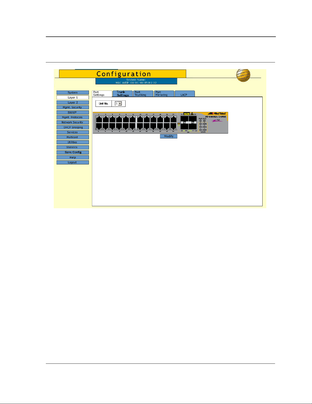
Figure 3: Port Settings Page
Getting Started
Using the Web Browser Interface
The port status indicators vary with context, for example the general port status indicators are as in the figure
above while port mirror indicators are different. Indicator legend descriptions are provided with each context of the
specific Zoom View.
Page 15
Page 16
Allied Telesis
AT-S94 Management Software Web Browser Interface User’s Guide
User Interface Components
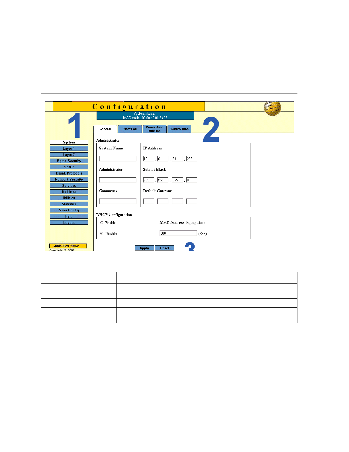
The System General Page example shows the interface components.
Figure 4: System General Page
The following table lists the interface components with their corresponding numbers:
Table 1: Interface Components
Component Description
1 Menu The Menu provides easy navigation through the main management software
features. In addition, the Menu provides general navigation options.
2 Tabs Provide navigation to configurable device sub-features.
3 Management Buttons Enable configuring parameters and navigation to other pages, see Using the
Management Buttons.
Page 16
Page 17
Getting Started
Using the Web Browser Interface
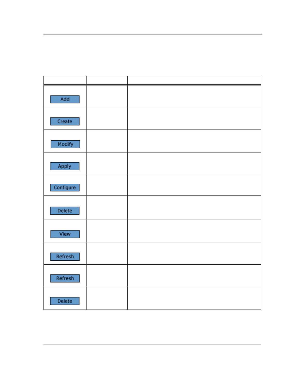
Using the Management Buttons
Management buttons provide an easy method of configuring device information, and include the following:
Table 2: Configuration Management Buttons
Button Button Name Description
Add Opens a page which creates new configuration entries.
Create Opens a page which creates new configuration entries.
Modify Modifies the configuration settings. The configuration change is
saved to the Running Configuration file and is maintained until
reset or power-up.
Apply Saves configuration changes to the device. The configuration
change is saved to the Running Configuration file and is
maintained until reset or power-up.
Configure Opens a page which creates or modifies configuration entries.
Delete Deletes the selected table and configuration entries.
View Displays detailed information for the current page/configuration.
Refresh Refreshes information displayed on the current page.
Reset Device reset. Resets the device information for all device
parameters according to current configuration.
Defaults Configuration reset. Resets the information for all parameters in
the current context (page/tab) to predefined defaults.
Page 17
Page 18
Allied Telesis
AT-S94 Management Software Web Browser Interface User’s Guide
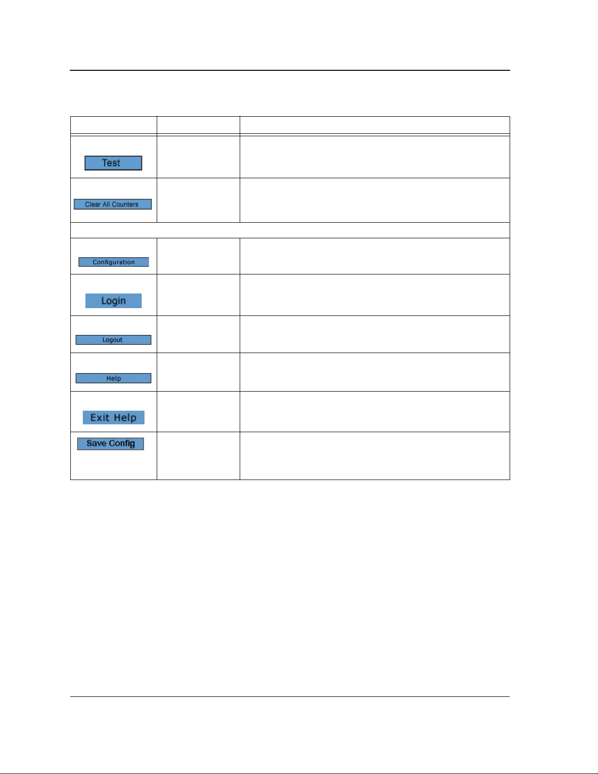
Table 2: Configuration Management Buttons
Button Button Name Description
Test Performs a diagnostic test.
Clear All Counters Removes all counters.
The application menu includes the following general purpose buttons:
Configuration Opens the default configuration page (System General).
Login Signs the user into the WBI, starts the management session.
Logout Signs the user out of the WBI, ending the management session.
Help Opens the online help page.
Exit Help Closes the online help page.
Save Config Used when configuration changes to the device need to be saved
as permanent. The configuration is saved as permanent by
copying the current Running Configuration file to the Startup
Configuration file.
Page 18
Page 19
Getting Started
Using the Web Browser Interface
Adding, Modifying and Deleting Information
The WBI contains and tables for configuring devices. User-defined information can be added, modified or deleted
in specific WBI pages.
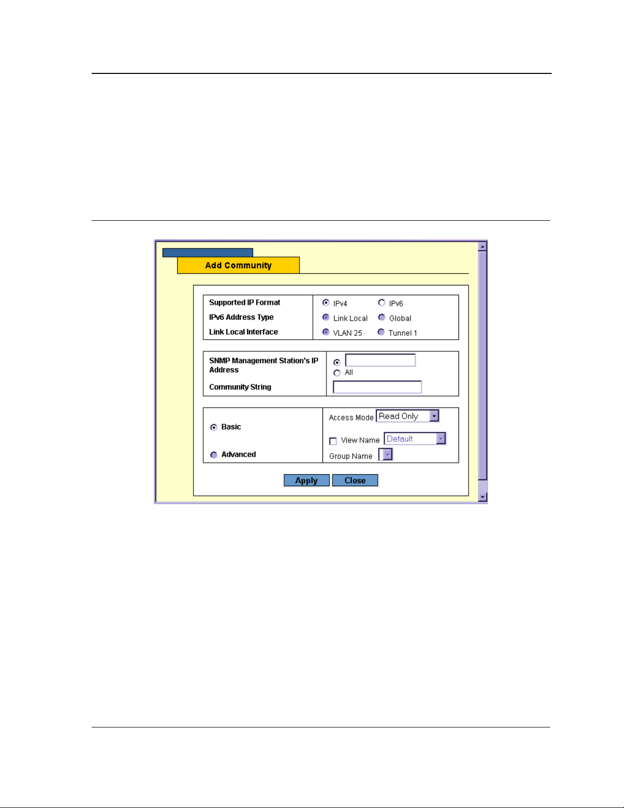
To add information to tables or WBI pages:
1. Open a WBI page.
2. Click Add. An Add page opens, for example, the Add Community Page:
Figure 5: Add Community Page
3. Define the fields.
4. Click Apply. The configuration information is saved, and the device is updated.
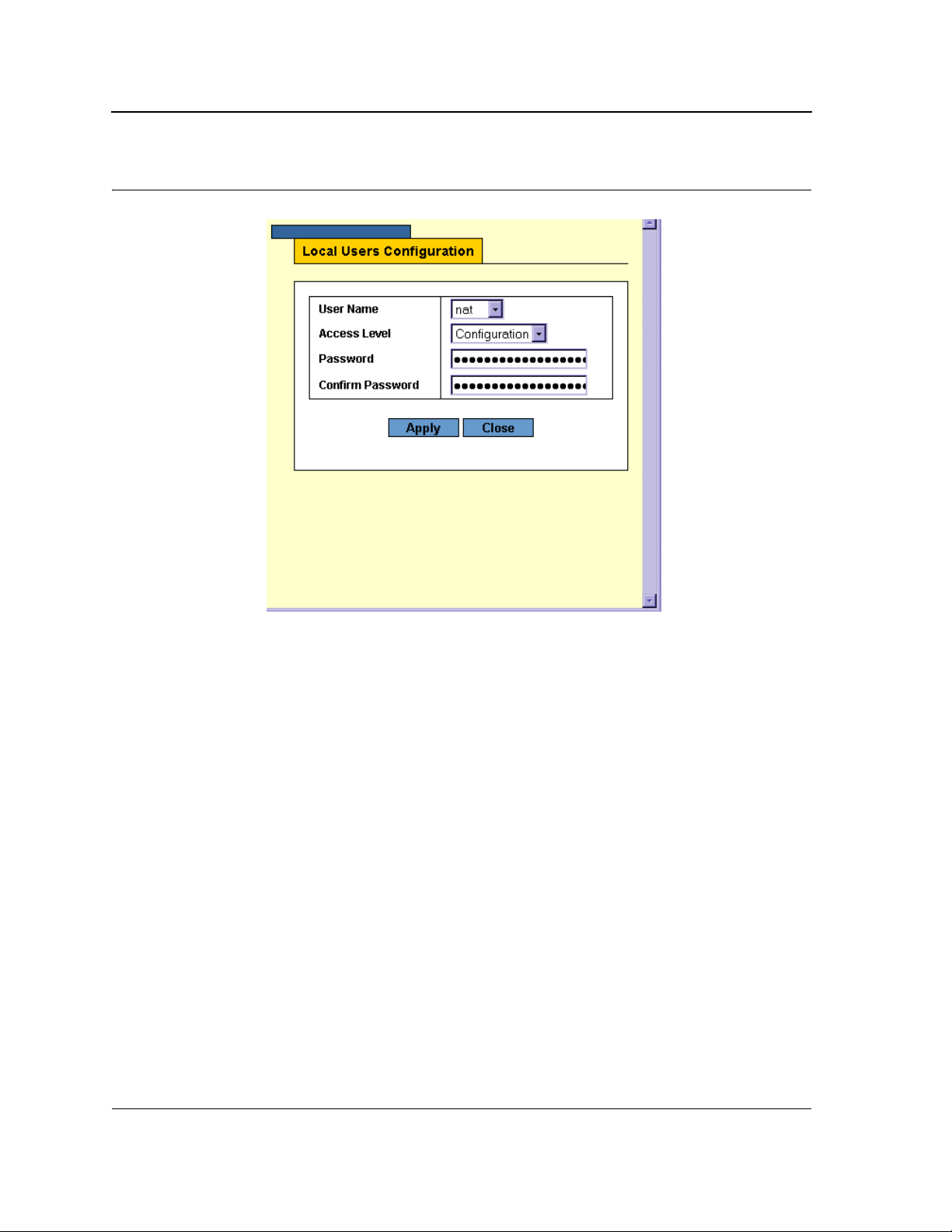
To modify information in tables or WBI pages:
1. Open a WBI page.
2. Select a table entry.
3. Click Modify. A Modify (or Settings) page opens, for example, the Local User Settings Page:
Page 19
Page 20
Allied Telesis
AT-S94 Management Software Web Browser Interface User’s Guide
Figure 6: Local User Settings Page
4. Define the fields.
5. Click Apply. The fields are modified, and the information is saved to the device.
To delete information in tables or WBI pages:
1. Open the WBI page.
2. Select a table row.
3. Click Delete. The information is deleted, and the device is updated.
Saving Configurations
User-defined information can be saved for permanent use or until next update, not just for the current session.
A configuration is saved as permanent by copying the current Running Configuration file to the Startup
Configuration file.
To save changes permanently:
• Click Save Config on the menu.
Page 20
Page 21
Getting Started
Note
Logging Out
Logging Out
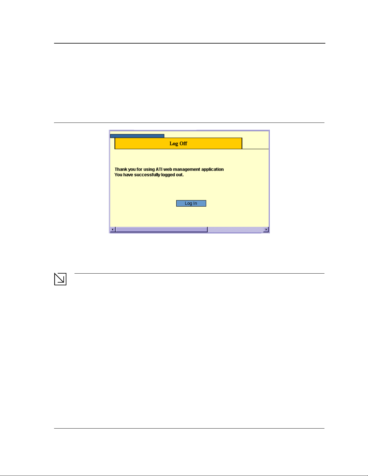
The Logout option enables the user to log out of the device thereby terminating the running session.
To log out:
• In any page, click Logout on the menu. The current management session is ended and the Log Off Page
opens:
Figure 7: Log Off Page
Resetting the Device
The Reset option enables resetting the device from a remote location.
Save all changes to the Running Configuration file before resetting the device. This prevents the current
device configuration from being lost. See also "System Utilities".
To reset the device:
1. In the System General Page, click Reset. You are prompted to confirm.
2. Click OK. The device is reset. Resetting the device ends the web browser management session. You must
restart the session to continue managing the device. After the device is reset, a prompt for a user name and
password displays.
3. Enter a user name and password to reconnect to the Web Interface.
To reset the device to the predefined default configuration:
• In the System General Page, click Defaults. The default settings are restored and the device is reset.
Configurable Login Banner
The system supports a text based banner that is configurable only via a CLI command to enable the telnet session
to display security messages above the login prompt prior to login.
Page 21
Page 22

Allied Telesis
AT-S94 Management Software Web Browser Interface User’s Guide
To compose a login banner:
• Enter the CLI command login_banner "text string". The text string length is a maximum of 159 characters
(surrounded by quotes).
To remove the login banner:
• Enter the CLI command login_banner "" with an empty string.
Page 22
Page 23
Defining System Information
Chapter 2. Defining System Information
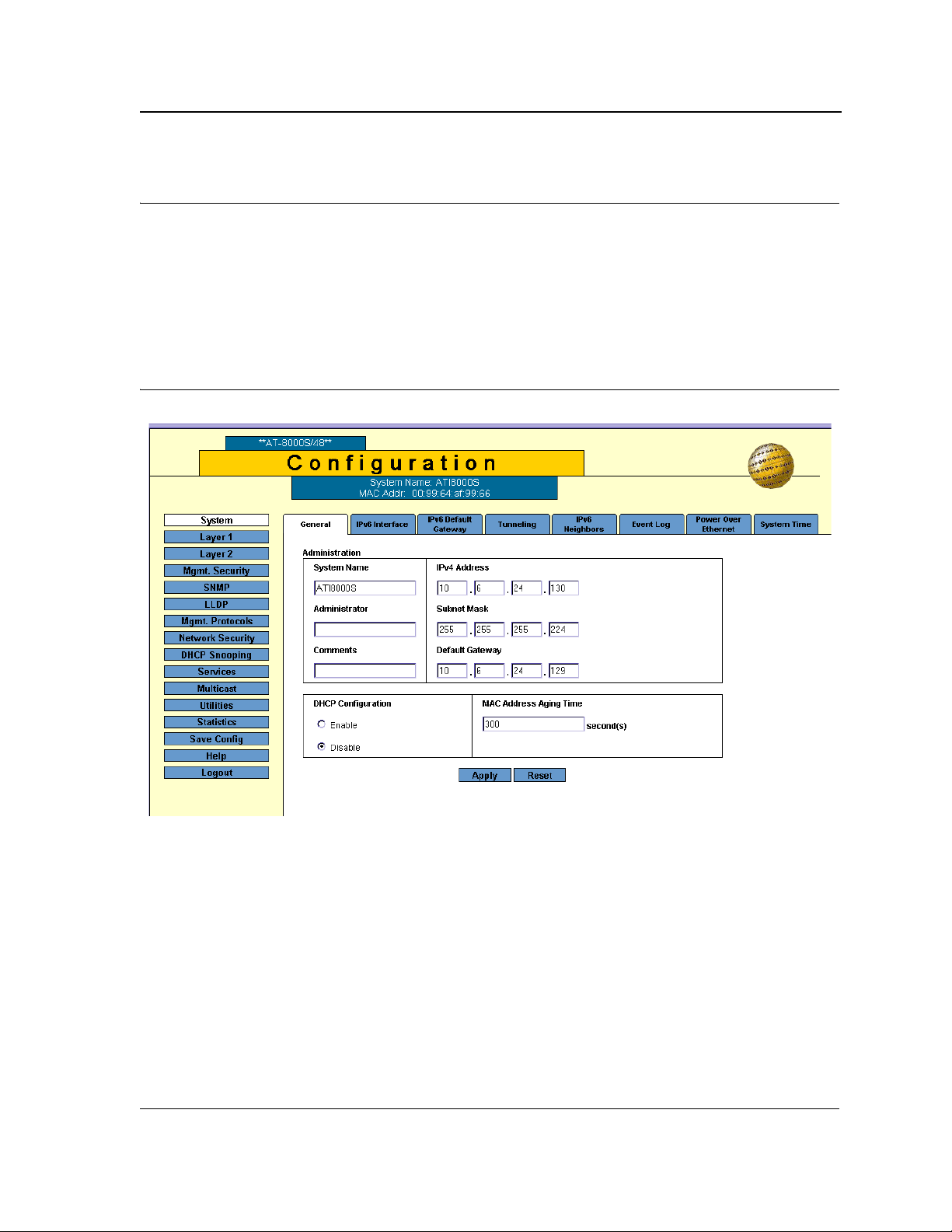
The System General Page contains general device information, including system name and its IPv4 addressing,
administrator and passwords information, Dynamic Host Configuration Protocol (DHCP) configuration and MAC
Address Aging Time.
To define the general system information:
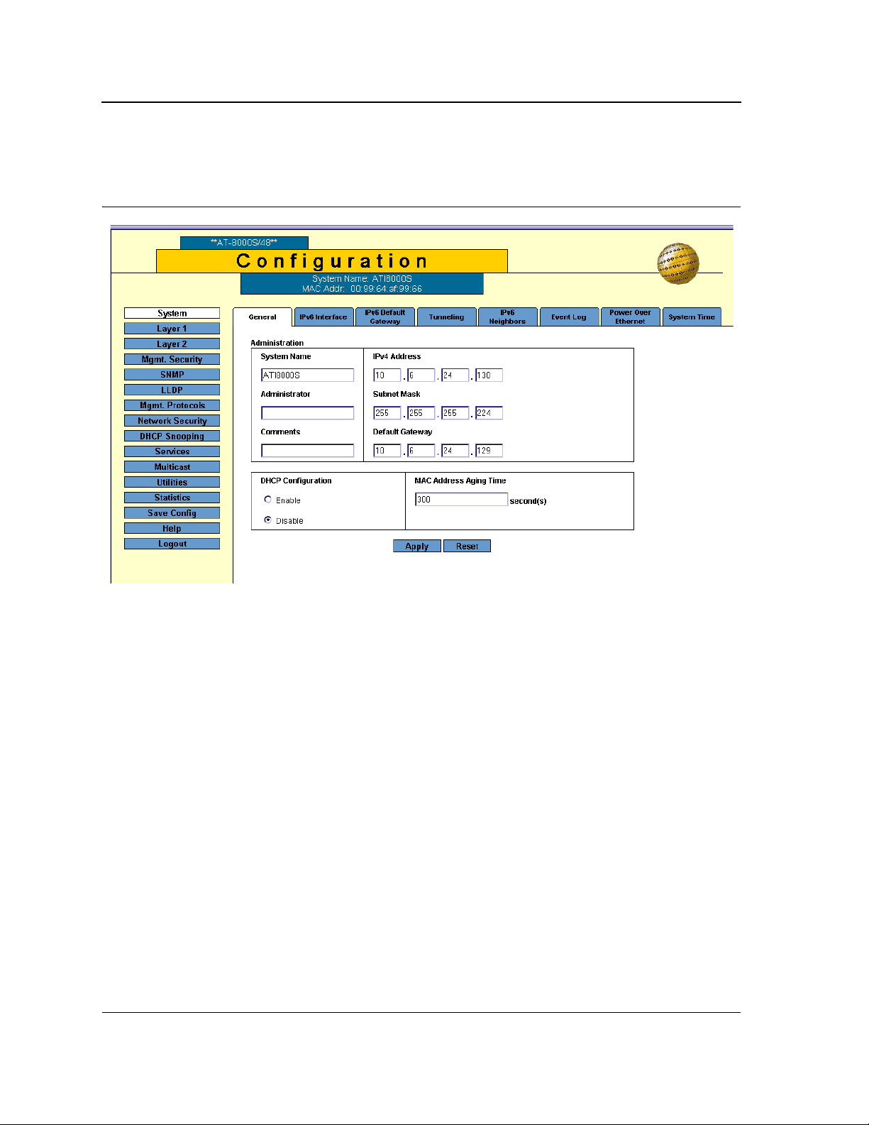
1. Click System > General. The System General Page opens:
Figure 8: System General Page
The System General PageSystem General PageSystem General Page comprises two sections: Administration
and DHCP Configuration.
Page 23
Page 24

Allied Telesis
Note
AT-S94 Management Software Web Browser Interface User’s Guide
The Administration section of theSystem General PageSystem General PageSystem General Page System
General Page contains the following fields:
• System Name — Indicates the user-defined name of the device. This is a required field.
The field range is 0-159 characters.
• Administrator — Indicates the name of the administrator responsible for managing the device. The field
range is 0-159 characters.
• Comments — (Optional) The user can add any comments about the device in this field, for example, fill in
the location of the device.
• IPv4 Address — Indicates the device’s IPv4 address.
• Subnet Mask — Indicates the device’s subnet mask.
• Default Gateway — The IP address of a router for remote management of the device. The address must be
entered in the format: xxx.xxx.xxx.xxx. The default value is 0.0.0.0.
Packets are forwarded to the default IP when frames are sent to a remote network via the default gateway.
The configured IP address must belong to the same subnet as one of the IP interfaces.
The DHCP Configuration section of theSystem General Page System General Page contains the following fields:
• DHCP Configuration — Indicates if the Dynamic Host Configuration Protocol (DHCP) is enabled.
– Enable — DHCP dynamically assigns IP addresses to devices on a network. With dynamic addressing,
a device can have a different IP address every time it connects to the network. If the DHCP client
software is activated, the device immediately begins to query the network for a DHCP server. The device
continues to query the network for its IP configuration until it receives a response. If the device and IP
address are manually assigned, that address is deleted and replaced by the IP address received from
the DHCP server.
– Disable — Disables DHCP on the device. In this case, the device, following reset, checks if the IP
address is already defined in the Startup Configuration. If not, the device tries to receive an IP address
from a BootIP server until either an IP address is received or the user defines the IP address manually.
• MAC Address Aging Time — The time interval an inactive dynamic MAC address can remain in the MAC
address table before it is deleted. The default time is 300 seconds, and the range is 10-630.
2. Define the relevant fields.
3. Click Apply. The system general information is defined and the device is updated.
4. Click Save Config on the menu to save the changes permanently.
Page 24
Page 25

Configuring IPv6
Chapter 3. Configuring IPv6
The device functions as an IPv6 compliant Host, as well as an IPv4 Host (also known as dual stack). This allows
device operation in a pure IPv6 network as well as in a combined IPv4/IPv6 network.
The primary change from IPv4 to IPv6 is the length of network addresses. IPv6 addresses are 128 bits long,
whereas IPv4 addresses are 32 bits; allowing a much larger address space.
This section contains information on configuring the Internet Protocol Version 6 (IPv6) of the device.
IPv6 Syntax
The 128-bit IPv6 address format is divided into eight groups of four hexadecimal digits. Abbreviation of this format
is done by replacing a group of zeros with double colons. The IPv6 address representation can be further
simplified by suppressing the leading zeros.
IPv6 Prefixes
While Unicast IPv6 addresses written with their prefix lengths are permitted, in practice their prefix lengths are
always 64 bits and therefore are not required to be expressed. Any prefix that is less than 64 bits is a route or
address range that is summarizing a portion of the IPv6 address space.
For every assignment of an IP address to an interface, the system runs the Duplicate Address Detection algorithm
to ensure uniqueness.
An intermediary transition mechanism is required for IPv6-only nodes to communicate with IPv6 nodes over an
IPv4 infrastructure. The tunneling mechanism implemented is the Intra-Site Automatic Tunnel Addressing
Protocol (ISATAP). This protocol treats the IPv4 network as a virtual IPv6 local-link, with each IPv4 address
mapped to a Link Local IPv6 address.
This section describes the following topics:
• Defining IPv6 Interfaces
• Defining the IPv6 Default Gateway
• Configuring Tunnels
• Defining IPv6 Neighbors
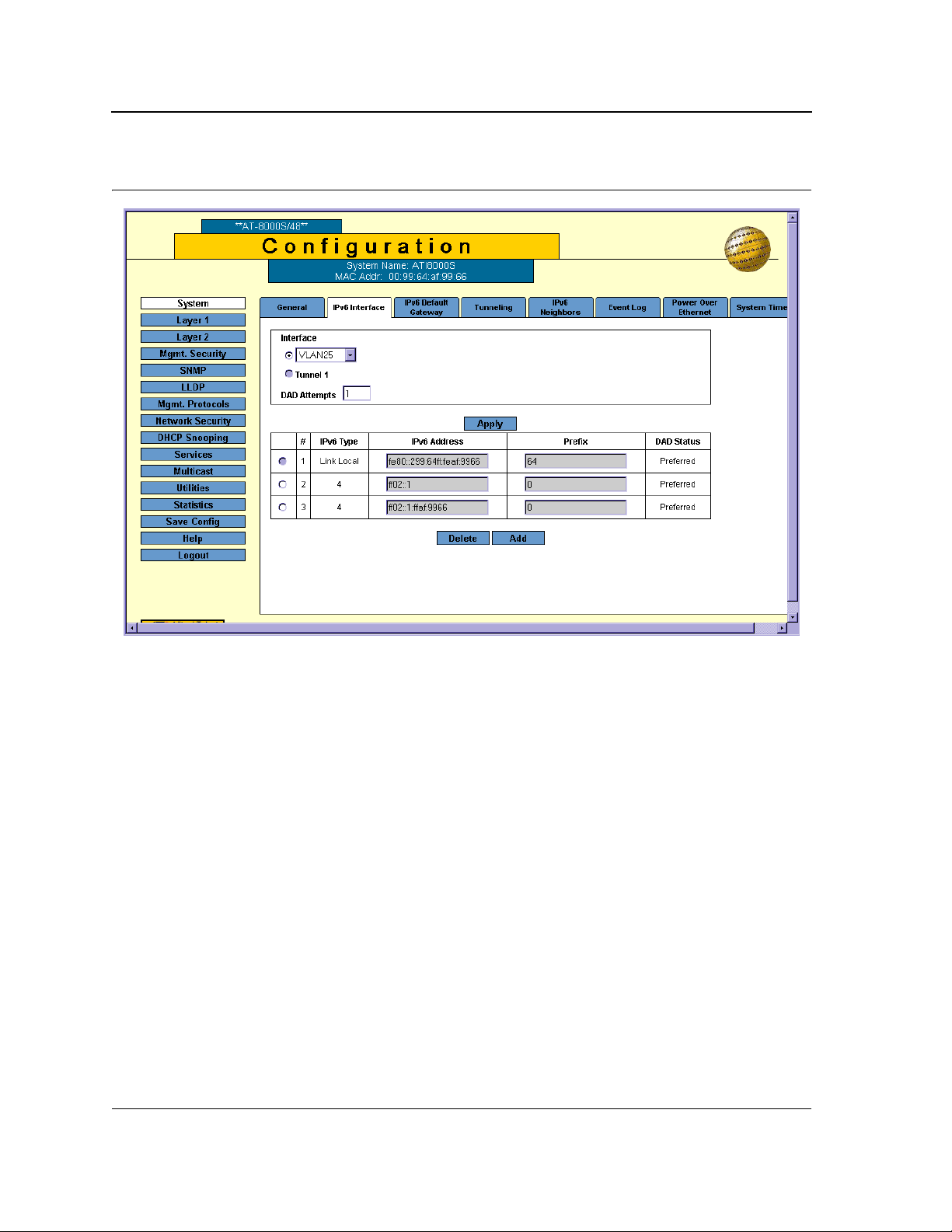
Defining IPv6 Interfaces
The IPv6 Interface Page provides parameters for defining an IPv6 interface. When an interface is selected on a
locally connected device, the system creates an IP interface and automatically configures a Link Local address on
the interface. The automatically generated Link Local IPv6 address cannot be removed.
In addition to the dynamically configured IPv6 interfaces, there are two types of static IP addresses that can be
configured on an IPv6 interface:
• Link Local Address — Defines a Link Local address that is non-routable and used for communication on the
same network only.
• Global Addresses — Defines a globally unique IPv6 address; visible and reachable from different subnets.
To define IPv6 Interfaces:
1. Click System > IPv6 Interface. The IPv6 Interface Page opens.
Page 25
Page 26
Allied Telesis
AT-S94 Management Software Web Browser Interface User’s Guide
Figure 9: IPv6 Interface Page
The IPv6 Interface Page contains the following fields:
• Interface — Indicates the interface on which the IPv6 interface is defined. The possible field values are:
– VLAN — Indicates the VLAN ID on which IPv6 is enabled.
– Tunnel1 — Indicates the IPv6 tunnel on which IPv6 is enabled.
• DAD Attempts — Defines the number of consecutive neighbor solicitation messages that are sent on an
interface while DAD is performed on Unicast IPv6 addresses on this interface. New addresses remain in a
tentative state while duplicate address detection is performed. The range is 0 - 600. A field value of 0,
disables duplicate address detection processing on the specified interface. A field value of 1 is the default.
The IPv6 Table on the IPv6 Interface Page displays the IPv6 addresses defined on the Interface. This table
contains the following fields:
• Delete Button — Deletes the selected IPv6 address. Entries that cannot be removed because they are
generated automatically by the system are unavailable. Only addresses configured by a user can be
removed. The possible field values are:
– Selected — Removes the selected IPv6 address.
– Cleared — Maintains the IPv6 address.
• IPv6 Type — Defines the type of configurable IPv6 IP address for the interface. The possible values are:
– Link Local — Defines a Link Local address; non routable and can be used for communication on the
same network only. A Link Local address has a prefix of 'FE80'.
Page 26
Page 27
Configuring IPv6
– Global — Defines a globally unique IPv6 address; visible and reachable from different subnets.
• IPv6 Address — Indicates the IPv6 address assigned to the interface.
• Prefix — Specifies the length of the IPv6 prefix. The length is a decimal value that indicates how many of the
high-order contiguous bits of the address comprise the prefix (the network portion of the address). The range
is 3 -128 (64 in the case EUI-64 parameter is used). The Prefix field is applicable only on a static IPv6
address defined as a Global IPv6 address.
• DAD Status — Displays the DAD Status which is the process of verifying and assuring an inserted IPv6
address is unique. This is a read-only parameter with the following field values:
– Tentative — Indicates the system is in process of IPv6 address duplication verification.
– Duplicate — Indicates the IPv6 address is being used by another host on the network. The duplicated
IPv6 address is suspended and is not used for sending or receiving any traffic.
– Active — Indicates the IPv6 address is set to active.
2. Select an Interface.
3. Define the DAD Attempts for an existing interface. DAD Attempts are disabled for Tunnel interface. The
range is 0 - 600.
4. Click Apply. The DAD Attempts are defined, and device is updated.
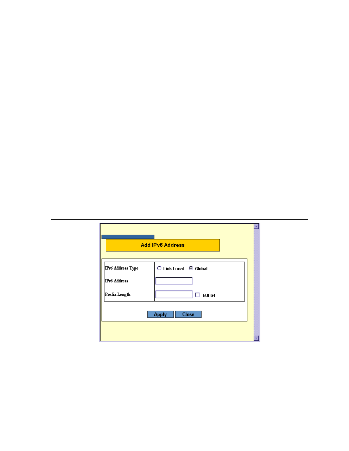
Adding Multiple IPv6 Addresses
The Add IPv6 Address Page allows the user to add multiple IPv6 addresses to an existing IPv6 interface.
1. Click Add. The Add IPv6 Address Page opens.
Figure 10: Add IPv6 Address Page
In addition to the fields in the Add IPv6 Address Page, the Add IPv6 Address Page contains the following field:
• EUI-64 — Indicates the interface ID (low-order 64 bits of the IPv6 address) is built from the system base MAC
address. The following fields options are:
– Checked — Enables the EUI-64 option. This option is relevant only to Global IPv6 addresses.
– Unchecked — Disables the EUI-64 option. This is the default value.
Page 27
Page 28

Allied Telesis
AT-S94 Management Software Web Browser Interface User’s Guide
2. Select an Interface to map to the IP address.
3. Select an IPv6 Address Type.
4. Define the IPv6 address. Selecting a Global in the IPv6 Address Type requires defining the Prefix Length or
selecting the EUI-64 check box.
5. Click Apply. The IPv6 address is mapped to the Interface, and the device is updated.
Page 28
Page 29
Configuring IPv6
Defining the IPv6 Default Gateway
The IPv6 Default Gateway Page enables you to configure the IPv6 address of the next hop that can be used to
reach the network. Two IPv6 Link-Local address formats are used: standard and one with a specified IPv6
interface identifier. For IPv6, the configuration of the default gateway is not mandatory, as hosts can automatically
learn of the existence of a router on the local network via the router advertisement procedure.
Unlike IPv4, the IPv6 default gateway can have multiple IPv6 addresses, which may include only one user-defined
static address and multiple dynamic addresses that are learned via router advertised message provided in the
IPv6 Default Gateway configuration. The user-defined default gateway has a higher precedence over
automatically advertised addresses. It should be noted that configuring a new static default gateway without
deleting the previously configured one overwrites the previous configuration.
• When removing an IP interface, all of its default gateway IP addresses are removed.
• An Alert message appears when attempting to insert a global IPv6 address.
• An Alert message appears when attempting to insert more than one user-defined address.
To define an IPv6 Preferred Router:
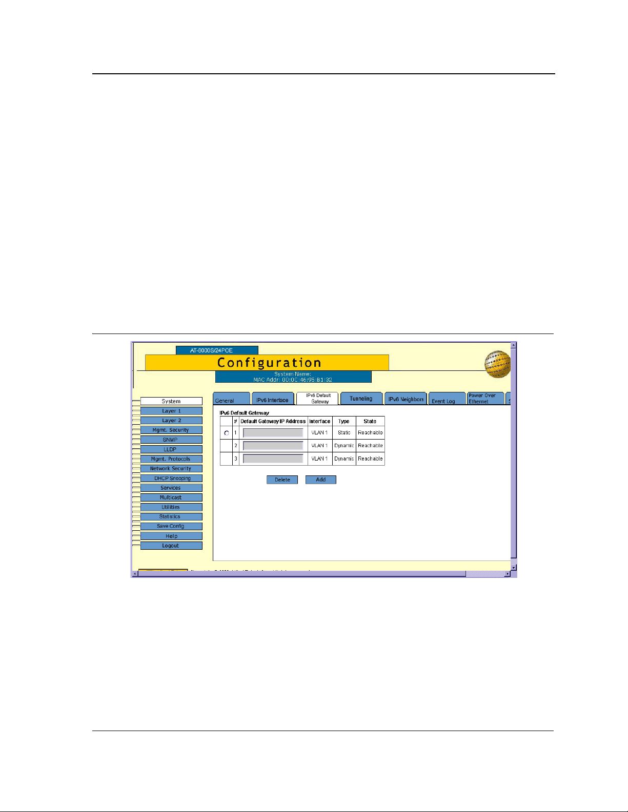
1. Click System > IPv6 Default Gateway. The IPv6 Default Gateway Page opens.
Figure 11: IPv6 Default Gateway Page
The IPv6 Default Gateway Page contains the following fields:
• The radio button is selected to delete/add/modify an entry.
• Default Gateway IPv6 Address — Displays the Link Local IPv6 address of the default gateway.
• Interface — Specifies the outgoing IPv6 interface through which the default gateway can be reached.
• Typ e — Specifies the means by which the default gateway was configured. The possible field values are:
– Static — Indicates the default gateway is user-defined.
Page 29
Page 30
Allied Telesis
AT-S94 Management Software Web Browser Interface User’s Guide
Dynamic — Indicates the default gateway is dynamically configured.
–
• State — Displays the default gateway status. The following states are available: Incomplete, Reachable,
Stale, Delay, Probe and Unreachable.
2. Select an Interface.
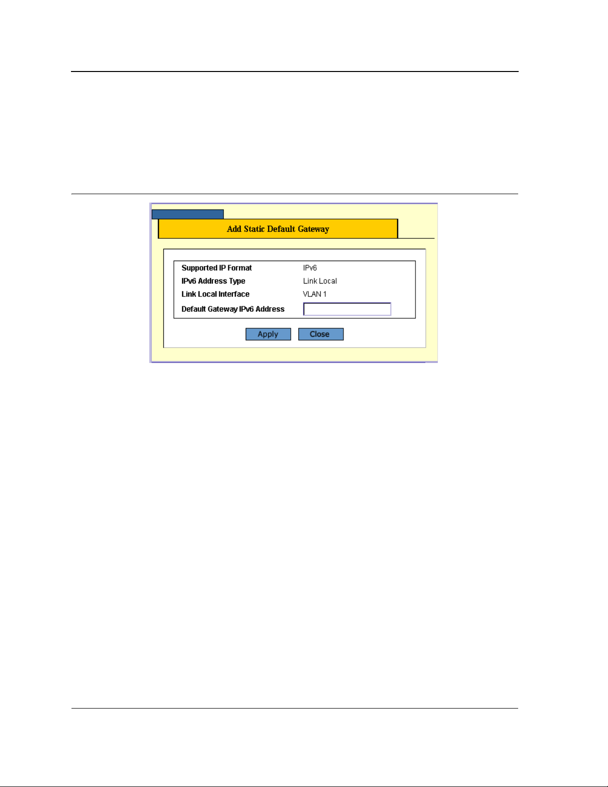
3. Click Add. The Add Static Default Gateway Page opens.
Figure 12: Add Static Default Gateway Page
4. Define the Default Gateway IPv6 Address field for the IP Interface. The address must be a valid IPv6
address, specified in hexadecimal using 16-bit values between colons. An example of an IPv6 address is
2031:0:130F:0:0:9C0:876A:130D and the compressed version is represented as
2031:0:130F::9C0:876A:130D.
5. Click Apply. The default gateway is defined, and the device is updated.
Page 30
Page 31

Configuring IPv6
Configuring Tunnels
The Tunneling Page defines the tunneling process on the device, which encapsulates IPv6 packets in IPv4
packets for delivery across an IPv4 network.
The Intra-Site Automatic Tunnel Addressing Protocol (ISATAP) address assignment and automatic tunneling
mechanism is used for Unicast communication between IPv6/IPv4 nodes in an IPv4 intranet.
To define Tunneling:
1. Click System > Tunneling. The Tunneling Page opens.
Figure 13: Tunneling Page
The Tunneling Page contains the following fields:
• Tun n e l Type — Indicates the tunnel type. The possible field values are:
– ISATAP — Indicates ISATAP is the selected tunnel type.
– None — IPv6 transition mechanism is not used. This is the default value.
• IPv4 Address — Specifies the source IPv4 address of a tunnel interface. The possible field values are:
– Manual — Specifies the IPv4 address to be used as the source address for packets sent on the tunnel
interface.
– Auto — The system minimum IPv4 address is used as the source address for packets sent on the tunnel
interface.
Page 31
Page 32

Allied Telesis
AT-S94 Management Software Web Browser Interface User’s Guide
None — Indicates that the tunnel local address is not set.
–
• ISATAP’s Router Domain Name — Specifies a global string that represents a specific automatic tunnel
router domain name. The default value is ISATAP.
• Domain Name Query Interval (10-3600) — Specifies the interval between DNS Queries (before the IP
address of the ISATAP router is known) for the automatic tunnel router domain name. The range is 10 - 3600
seconds. The default is 10 seconds.
• ISATAP Router Solicitation Interval (10-3600) — Specifies the interval between router solicitations
messages when there is no active router. The range is 10 - 3600 seconds. The default is 10.
• ISATAP Robustness (1-20) — Specifies the number of DNS Query/ Router Solicitation refresh messages
that the device sends. The range is 1 - 20 seconds. The default is 3.
2. Click Apply. The Tunnel is defined, and the device is updated.
Defining IPv6 Neighbors
The IPv6 Neighbors Page contains information for defining IPv6 Neighbors which is similar to the functionality of
the IPv4 Address Resolution Protocol (ARP). IPv6 Neighbors enables detecting Link Local addresses within the
same subnet, and includes a database for maintaining reachability information about the active neighbors paths.
The device supports a total of up to 256 neighbors obtained either statically or dynamically.
When removing an IP interface, all neighbors learned statically and dynamically are removed.
To define IPv6 Neighbors:
1. Click System > IPv6 Neighbors. The IPv6 Neighbors Page opens.
Figure 14: IPv6 Neighbors Page
Page 32
Page 33

Configuring IPv6
The IPv6 Neighbors Page contains the following fields:
View IPv6 Neighbors
•
View Static — Displays the static IPv6 address entries from the IPv6 Neighbor Table.
• View Dynamic — Displays the dynamic IPv6 address entries from the IPv6 Neighbor Table.
• View IPv6 Address — Displays the currently configured neighbor IPv6 address entries from the IPv6
Neighbor Table. The address must be a valid IPv6 address, specified in hexadecimal using 16-bit values
between colons.
• View MAC Address — Displays the MAC address mapped to the IPv6 address.
IPv6 Neighbors
Clear Table — Deletes the entries in the IPv6 Neighbor Table. The possible field values are:
•
– Static Only — Deletes the static IPv6 address entries from the IPv6 Neighbor Table.
– Dynamic Only — Deletes the dynamic IPv6 address entries from the IPv6 Neighbor Table.
– All Dynamic and Static — Deletes the IPv6 Neighbor Table static and dynamic address entries.
• The radio button is selected to delete/add/modify an entry.
• Interface — Displays the interface (VLAN) on which the IPv6 interface is configured.
• IPv6 Address — Defines the currently configured neighbor IPv6 address. The address must be a valid IPv6
address, specified in hexadecimal using 16-bit values between colons.
• MAC Address — Displays the MAC address mapped to the IPv6 address.
• Typ e — Displays the type of the neighbor discovery cache information entry. The possible field values are:
– Static — Shows static neighbor discovery cache entries.
– Dynamic — Shows dynamic neighbor discovery cache entries.
• State — Displays the IPv6 Neighbor status. The following states are available: Incomplete, Reachable, Stale,
Delay and Probe.
2. Select an interface.
Page 33
Page 34

Allied Telesis
Notes
AT-S94 Management Software Web Browser Interface User’s Guide
3. Click Add. The Add IPv6 Neighbor Page opens.
Figure 15: Add IPv6 Neighbor Page
4. Define the static IPv6 Address and MAC Address fields.
5. Click Apply. The IPv6 Neighbors entry is defined, and the device is updated.
To modify IPv6 Neighbor entries:
1. Click System > IPv6 Neighbors. The IPv6 Neighbors Page opens.
2. Select the IPv6 Address field to be edited.
3. Click Modify. The IPv6 Neighbor Configuration Page opens.
• Static IPv6 addresses require a MAC address whereas dynamic addresses are configured
automatically.
• Selecting the Dynamic option in the Type field, disables the fields and prevents reselecting the Static
option.
4. Define the MAC Address for the static IPv6 address.
5. Click Apply. The IPv6 Neighbor entry is modified and the device is defined.
Page 34
Page 35

To view IPv6 Neighbor entries:
1. Click System > IPv6 Neighbors. The IPv6 Neighbors Page opens.
2. Select an interface.
3. Click View. The View IPv6 Neighbors Page opens.
Figure 16: View IPv6 Neighbors Page
Configuring IPv6
The View IPv6 Neighbors Page contains the following fields:
• Interface — Displays the interface (VLAN) on which the IPv6 interface is configured.
• IPv6 Address — Defines the currently configured neighbor IPv6 address. The address must be a valid IPv6
address, specified in hexadecimal using 16-bit values between colons.
• MAC Address — Displays the MAC address mapped to the IPv6 address.
• Typ e — Displays the type of the neighbor discovery cache information entry. The possible field values are:
– Static — Shows static neighbor discovery cache entries.
– Dynamic — Shows dynamic neighbor discovery cache entries.
• State — Displays the IPv6 Neighbor status. The field possible values are:
– Incomplete — Indicates address resolution is in process. The neighbor has not yet responded.
– Reachable — Indicates the neighbor is known to be reachable.
– Stale — Indicates the previously known neighbor is no longer reachable. No action is taken to verify its
reachability, until traffic need to be sent.
– Delay — Indicates the previously known neighbor is no longer reachable. The Interface is in Delay state
for a predefined Delay Time that if no reachability confirmation is received, the state changes to Probe.
– Probe — Indicates the neighbor is no longer known to be reachable, and Unicast Neighbor Solicitation
probes are being sent to verify reachability.
Page 35
Page 36

Allied Telesis
AT-S94 Management Software Web Browser Interface User’s Guide
Page 36
Page 37

Configuring System Time
Chapter 4. Configuring System Time
The System Time Page provides information for configuring system time parameters, including:
• Setting the System Clock
• Configuring SNTP
• Configuring Daylight Saving Time
Setting the System Clock
The System Time Page contains fields for defining system time parameters for both the local hardware clock and
the external SNTP clock. If the system time is kept using an external SNTP clock, and the external SNTP clock
fails, the system time reverts to the local hardware clock. Daylight Savings Time can be enabled on the device.
To configure the system clock time:
1. Click System > System Time. The System Time Page opens:
Figure 17: System Time Page
The Clock Source and System Time sections of the System Time Page contain the following fields:
• Clock Source — The source used to set the system clock. The possible field values are:
– Local Settings — Indicates that the clock is set locally.
Page 37
Page 38

Allied Telesis
AT-S94 Management Software Web Browser Interface User’s Guide
SNTP — Indicates that the system time is set via an SNTP server.
–
• System Time — Sets the local clock time. The field format is HH:MM:SS. For example: 21:15:03.
• System Date — Sets the system date. The field format is Day/Month/Year. For example: 04/May/2050
(May 4, 2050).
• Time Zone Offset — The difference between Greenwich Mean Time (GMT) and local time. For example, the
Time Zone Offset for Paris is GMT +1, while the Time Zone Offset for New York is GMT –5.
To set the system clock:
1. Select the system time mode.
2. Define the System Date, System Time and Time Zone Offset fields.
3. Click Apply in each section. The local system clock settings are saved, and the device is updated.
4. Click Save Config on the menu to save the changes permanently.
Configuring SNTP
The device supports the Simple Network Time Protocol (SNTP). SNTP assures accurate network device clock
time synchronization up to the millisecond. Time synchronization is performed by a network SNTP server. The
device operates only as an SNTP client, and cannot provide time services to other systems. The device can poll
the following server types for the server time:
• Unicast
• Anycast
• Broadcast
Time sources are established by stratums. Stratums define the accuracy of the reference clock. The higher the
stratum (where zero is the highest), the more accurate the clock. The device receives time from stratum 1 and
above. The following is an example of stratums:
Stratum 0 — A real time clock (such as a GPS system) is used as the time source.
Stratum 1 — A server that is directly linked to a Stratum 0 time source is used. Stratum 1 time servers provide
primary network time standards.
Stratum 2 — The time source is distanced from the Stratum 1 server over a network path. For example, a Stratum
2 server receives the time over a network link, via NTP, from a Stratum 1 server.
Polling for Unicast Time Information
Polling for Unicast information is used for polling a server for which the IP address is known. T1 - T4 are used to
determine the server time. This is the preferred method for synchronizing device time.
Polling for Anycast Time Information
Polling for Anycast information is used when the SNTP server IP address is unknown. The first Anycast server to
return a response is used to set the time value. Time levels T3 and T4 are used to determine the server time.
Using Anycast time information for synchronizing device time is preferred to using Broadcast time information.
Broadcast Time Information
Broadcast information is used when the server IP address is unknown. When a Broadcast message is sent from
an SNTP server, the SNTP client listens for the response. The SNTP client neither sends time information
requests nor receives responses from the Broadcast server.
Message Digest 5 (MD5) Authentication safeguards device synchronization paths to SNTP servers. MD5 is an
algorithm that produces a 128-bit hash. MD5 is a variation of MD4, and increases MD4 security. MD5 verifies the
integrity of the communication, authenticates the origin of the communication.
Page 38
Page 39

Configuring System Time
To define SNTP global parameters:
1. Click System > System Time. The System Time Page opens.
The Simple Network Time Protocol (SNTP) section of the System Time Page contains the following fields:
• Status — Indicates if SNTP is enabled on the device. The possible field values are:
– Disabled — Indicates that SNTP is disabled.
– Enabled — Indicates that SNTP is enabled.
• Poll Interval — Defines the interval (in seconds) at which the SNTP server is polled for Unicast information.
The Poll Interval default is 1024 seconds.
• Server IP Address — Displays a user-defined SNTP server IP address.
• Supported IP Format — Indicates the supported Internet Protocol on the device. The possible field values
are:
– IPv4 — Indicates that IPv4 is supported.
– IPv6 — Indicates that IPv6 is supported.
• IPv6 Address Type — If IPv6 is selected as a Supported IP Format, the IPv6 address type should be
selected. The possible field values are:
– Link Local — Indicates that link local addressing is supported by the interface.
– Global — Indicates that global Unicast addressing is supported by the interface.
• Link Local Interface — Indicates the interface type. The possible field values are:
– VLAN — Indicates that VLAN 1 is supported.
– Tunnel — Indicates that ISATAP tunneling (Tunnel 1) mechanism is supported.
2. Select the SNTP Status, Supported IP Format and when applicable the IPv6 Address Type and Link Local
Interface.
3. Define the Server IP Address and the Poll Interval fields.
4. Click Apply. The SNTP global settings are defined, and the device is updated.
5. Click Save Config on the menu to save the changes permanently.
Configuring Daylight Saving Time
To configure Daylight Saving Time:
1. Click System > System Time. The System Time Page opens:
The Additional Time Parameters section of the System Time Page contains the following fields:
• Daylight Saving — Enables automatic Daylight Saving Time (DST) on the device based on the device’s
location. There are two types of daylight settings, either by a specific date in a particular year or a recurring
setting irrespective of the year. For a specific setting in a particular year complete the Daylight Savings area,
and for a recurring setting, complete the Recurring area. The possible field values are:
– USA — The device changes to DST at 2:00 a.m. on the second Sunday of March, and reverts to
standard time at 2:00 a.m. on the first Sunday of November.
– European — The device changes to DST at 1:00 am on the last Sunday in March and reverts to standard
time at 1:00 am on the last Sunday in October. The European option applies to EU members, and other
European countries using the EU standard.
Page 39
Page 40

Allied Telesis
AT-S94 Management Software Web Browser Interface User’s Guide
Other — The DST definitions are user-defined based on the device locality. If Custom is selected, the
–
From and To fields must be defined.
• Time Set Offset — Used for non-USA and European countries to set the amount of time for DST
(in minutes). The default time is 60 minutes. The range is 1-1440 minutes.
• From — Indicates the time that DST begins in countries other than the USA and Europe, in the format Day/
Month/Year in one field and HH:MM in another. For example, if DST begins on October 25, 2007 at 5:00 am,
the two fields should be set to 25/Oct./07 and 05:00. The possible field values are:
– Date — The date on which DST begins. The possible field range is 1-31.
– Month — The month of the year in which DST begins. The possible field range is Jan.-Dec.
– Year — The year in which the configured DST begins.
– Time — The time at which DST begins. The field format is HH:MM. For example: 05:30.
• To — Indicates the time that DST ends in countries other than the USA and Europe, in the format Day/Month/
Year in one field and HH:MM in another. For example, if DST ends on March 23, 2008 at midnight, the two
fields should be 23/Mar/08 and 00:00. The possible field values are:
– Date — The date on which DST ends. The possible field range is 1-31.
– Month — The month of the year in which DST ends. The possible field range is Jan-Dec.
– Year— The year in which the configured DST ends.
– Time — The time at which DST starts. The field format is HH:MM. For example: 05:30.
• Recurring — Enables user-defined DST for countries in which DST is constant from year to year, other than
the USA and Europe.
• From — The time that DST begins each year. In the example, DST begins locally every first Sunday in April
at midnight. The possible field values are:
– Day — The day of the week from which DST begins every year. The possible field range is Sunday-
Saturday.
– Week — The week within the month from which DST begins every year. The possible field range is 1-5.
– Month — The month of the year in which DST begins every year. The possible field range is Jan.-Dec.
– Time — The time at which DST begins every year. The field format is Hour:Minute. For example: 02:10.
• To — The time that DST ends each year. In the example, DST ends locally every first Sunday in October at
midnight. The possible field values are:
– Day — The day of the week at which DST ends every year. The possible field range is Sunday-Saturday.
– Week — The week within the month at which DST ends every year. The possible field range is 1-5.
– Month — The month of the year in which DST ends every year. The possible field range is Jan.-Dec.
– Time — The time at which DST ends every year. The field format is HH:MM. For example: 05:30.
2. To configure the device to automatically switch to DST, select Daylight Savings and select either USA,
European, or Other. If you select Other, you must define its From and To fields. To configure DST parameters
that recur every year, select Recurring and define its From and To fields.
3. Click Apply. The DST settings are saved, and the device is updated.
4. Click Save Config on the menu to save the changes permanently.
Page 40
Page 41

Configuring System Time
Daylight Savings Time by Country
The following is a list of Daylight Savings Time start and end dates by country:
• Albania — From the last weekend of March until the last weekend of October.
• Australia — From the end of October until the end of March.
• Australia - Tasmania — From the beginning of October until the end of March.
• Armenia — From the last weekend of March until the last weekend of October.
• Austria — From the last weekend of March until the last weekend of October.
• Bahamas — From April to October, in conjunction with Daylight Savings Time in the United States.
• Belarus — From the last weekend of March until the last weekend of October.
• Belgium — From the last weekend of March until the last weekend of October.
• Brazil — From the third Sunday in October until the third Saturday in March. During the period of Daylight
Saving Time, Brazilian clocks go forward one hour in most of the Brazilian southeast.
• Chile — In Easter Island, from March 9 until October 12. In the rest of the country, from the first Sunday in
March or after 9th March.
• China — China does not use Daylight Saving Time.
• Canada — From the first Sunday in April until the last Sunday of October. Daylight Saving Time is usually
regulated by provincial and territorial governments. Exceptions may exist in certain municipalities.
• Cuba — From the last Sunday of March to the last Sunday of October.
• Cyprus — From the last weekend of March until the last weekend of October.
• Denmark — From the last weekend of March until the last weekend of October.
• Egypt — From the last Friday in April until the last Thursday in September.
• Estonia — From the last weekend of March until the last weekend of October.
• Finland — From the last weekend of March until the last weekend of October.
• France — From the last weekend of March until the last weekend of October.
• Germany — From the last weekend of March until the last weekend of October.
• Greece — From the last weekend of March until the last weekend of October.
• Hungary — From the last weekend of March until the last weekend of October.
• India — India does not use Daylight Saving Time.
• Iran — From Farvardin 1 until Mehr 1.
• Iraq — From April 1 until October 1.
• Ireland — From the last weekend of March until the last weekend of October.
• Israel — Varies year-to-year.
• Italy — From the last weekend of March until the last weekend of October.
• Japan — Japan does not use Daylight Saving Time.
• Jordan — From the last weekend of March until the last weekend of October.
• Latvia — From the last weekend of March until the last weekend of October.
• Lebanon — From the last weekend of March until the last weekend of October.
• Lithuania — From the last weekend of March until the last weekend of October.
• Luxembourg — From the last weekend of March until the last weekend of October.
• Macedonia — From the last weekend of March until the last weekend of October.
• Mexico — From the first Sunday in April at 02:00 to the last Sunday in October at 02:00.
• Moldova — From the last weekend of March until the last weekend of October.
• Montenegro — From the last weekend of March until the last weekend of October.
• Netherlands — From the last weekend of March until the last weekend of October.
Page 41
Page 42

Allied Telesis
AT-S94 Management Software Web Browser Interface User’s Guide
• New Zealand — From the first Sunday in October until the first Sunday on or after March 15.
• Norway — From the last weekend of March until the last weekend of October.
• Paraguay — From April 6 until September 7.
• Poland — From the last weekend of March until the last weekend of October.
• Portugal — From the last weekend of March until the last weekend of October.
• Romania — From the last weekend of March until the last weekend of October.
• Russia — From the last weekend of March until the last weekend of October.
• Serbia — From the last weekend of March until the last weekend of October.
• Slovak Republic - From the last weekend of March until the last weekend of October.
• South Africa — South Africa does not use Daylight Saving Time.
• Spain — From the last weekend of March until the last weekend of October.
• Sweden — From the last weekend of March until the last weekend of October.
• Switzerland — From the last weekend of March until the last weekend of October.
• Syria — From March 31 until October 30.
• Tai wan — Taiwan does not use Daylight Saving Time.
• Turkey — From the last weekend of March until the last weekend of October.
• United Kingdom — From the last weekend of March until the last weekend of October.
• United States of America — From the second Sunday in March at 02:00 to the first Sunday in November at
02:00.
Page 42
Page 43

Configuring Device Security
Configuring Management Security
Chapter 5. Configuring Device Security
This section describes setting security parameters for ports, device management methods, users, and servers.
This section contains the following topics:
• Configuring Management Security
• Configuring Server Based Authentication
• Configuring Network Security
• Defining Access Control
Configuring Management Security
This section provides information for configuring device management security, device authentication methods,
users and passwords.
This section includes the following topics:
• Defining Access Profiles
• Defining Profile Rules
• Defining Authentication Profiles
• Mapping Authentication Profiles
Defining Access Profiles
Access profiles are profiles and rules for accessing the device. Access to management functions can be limited to
user groups. User groups are defined for interfaces according to IP addresses or IP subnets. Access profiles
contain management methods for accessing and managing the device. The device management methods
include:
• All
• Telnet
• Secure Telnet (SSH)
• HTTP
• Secure HTTP (HTTPS)
Management access to different management methods may differ between user groups. For example, User
Group 1 can access the device module only via an HTTPS session, while User Group 2 can access the device
module via both HTTPS and Telnet sessions. The Access Profile Page contains the currently configured access
profiles and their activity status.
Assigning an access profile to an interface denies access via other interfaces. If an access profile is assigned to
any interface, the device can be accessed by all interfaces.
Page 43
Page 44

Allied Telesis
AT-S94 Management Software Web Browser Interface User’s Guide
To define access profiles:
1. Click Mgmt. Security > Access Profile. The Access Profile Page opens:
Figure 18: Access Profile Page
The Access Profile Page contains a table listing the currently defined profiles and their active status:
• Access Profile Name — The name of the profile. The access profile name can contain up to 32 characters.
• Current Active Access Profile — Indicates if the profile is currently active. The possible field values are:
– Checked — The access profile is currently active. Access Profiles cannot be deleted when active.
– Unchecked — Disables the active access profile.
Page 44
Page 45

2. Click Add. The Add Access Profile Page opens:
Figure 19: Add Access Profile Page
Configuring Device Security
Configuring Management Security
In addition to the Access Profile Page, the Add Access Profile Page contains the following fields:
• Access Profile Name — Defines the name of a new access profile.
• Rule Priority — Defines the rule priority. When the packet is matched to a rule, user groups are either
granted permission or denied device management access. The rule number is essential to matching packets
to rules, as packets are matched on a first-fit basis. The rule priorities are assigned in the Profile Rules Page.
• Management Method — Defines the management method for which the rule is defined. Users with this
access profile can access the device using the management method selected. The possible field values are:
– All — Assigns all management methods to the rule.
– Teln et — Assigns Telnet access to the rule. If selected, users accessing the device using Telnet meeting
access profile criteria are permitted or denied access to the device.
– Secure Telnet (SSH) — Assigns SSH access to the rule. If selected, users accessing the device using
Telnet meeting access profile criteria are permitted or denied access to the device.
– HTTP — Assigns HTTP access to the rule. If selected, users accessing the device using HTTP meeting
access profile criteria are permitted or denied access to the device.
– Secure HTTP (HTTPS) — Assigns HTTPS access to the rule. If selected, users accessing the device
using HTTPS meeting access profile criteria are permitted or denied access to the device.
– SNMP — Assigns SNMP access to the rule. If selected, users accessing the device using SNMP
meeting access profile criteria are permitted or denied access to the device.
• Interface — Defines the interface on which the access profile is defined. The possible field values are:
– Port — Specifies the port on which the access profile is defined.
– Tru nk — Specifies the trunk on which the access profile is defined.
Page 45
Page 46

Allied Telesis
Note
AT-S94 Management Software Web Browser Interface User’s Guide
VLAN — Specifies the VLAN on which the access profile is defined.
–
• Supported IP Format — Indicates the supported Internet Protocol on the device. Only IPv6 Global is
supported
• IPv6 Address Type — Defines the type of configurable static IPv6 IP address for an interface. The possible
field values are:
– Link Local — Specifies that link local addressing is supported by the interface.
– Global — Specifies that global Unicast addressing is supported by the interface.
• Link Local Interface — Specifies the interface on which IPv6 processing is enabled. The possible field
values are:
– VLAN 1 — Specifies that VLAN 1 is supported.
– None — Disables IPv6 support on the interface. This option is only available the first time you configure
the access profile.
– Tunnel 1 — Specifies that ISATAP tunneling (Tunnel 1) mechanism is supported.
You must initially select the VLAN 1 option to enable IPv6 support on the interface. After doing so, the
VLAN 1 and Tunnel 1 options are available, but the None option is not.
• Source IP Address — Defines the interface source IP address to which the access profile applies.
The Source IP Address field is valid for a subnetwork.
– Network Mask — Defines the network mask of the source IP address.
– Prefix Length — Defines the number of bits that comprise the source IP address prefix, or the network
mask of the source IP address.
• Action — Defines the action attached to the access rule. The possible field values are:
– Permit — Permits access to the device.
– Deny — Denies access to the device. This is the default.
3. Define the fields.
4. Click Apply. The access profile is saved and the device is updated.
5. Click Save Config on the menu to save the changes permanently.
Page 46
Page 47

Configuring Device Security
Configuring Management Security
Defining Profile Rules
Access profiles can contain up to 128 rules that determine which users can manage the device module, and by
which methods. Users can also be blocked from accessing the device. Rules are composed of filters including:
• Rule Priority
• Interface
• Management Method
• IP Address
• Prefix Length
• Forwarding Action
To define profile rules:
1. Click Mgmt. Security > Profile Rules: The Profile Rules Page opens:
Figure 20: Profile Rules Page
The Profile Rules Page contains the following fields:
• Access Profile Name — Displays the access profile to which the rule is attached.
• Priority — Defines the rule priority. When the packet is matched to a rule, user groups are either granted
permission or denied device management access. The rule number is essential to matching packets to rules,
as packets are matched on a first-fit basis.
• Interface — Indicates the interface type to which the rule applies. The possible field values are:
– Port — Attaches the rule to the selected port.
– Tru nk — Attaches the rule to the selected trunk.
– VLAN — Attaches the rule to the selected VLAN.
Page 47
Page 48

Allied Telesis
AT-S94 Management Software Web Browser Interface User’s Guide
• Management Method — Defines the management method for which the rule is defined. Users with this
access profile can access the device using the management method selected. The possible field values are:
– All — Assigns all management methods to the rule.
– Teln et — Assigns Telnet access to the rule. If selected, users accessing the device using Telnet meeting
access profile criteria are permitted or denied access to the device.
– Secure Telnet (SSH) — Assigns SSH access to the rule. If selected, users accessing the device using
Telnet meeting access profile criteria are permitted or denied access to the device.
– HTTP — Assigns HTTP access to the rule. If selected, users accessing the device using HTTP meeting
access profile criteria are permitted or denied access to the device.
– Secure HTTP (HTTPS) — Assigns HTTPS access to the rule. If selected, users accessing the device
using HTTPS meeting access profile criteria are permitted or denied access to the device.
– SNMP — Assigns SNMP access to the rule. If selected, users accessing the device using SNMP
meeting access profile criteria are permitted or denied access to the device.
• Source IP Address — Defines the interface source IP address to which the rule applies.
• Prefix Length — Defines the number of bits that comprise the source IP address prefix, or the network mask
of the source IP address.
• Action — Defines the action attached to the rule. The possible field values are:
– Permit — Permits access to the device.
– Deny — Denies access to the device. This is the default.
2. Click Add. The Add Profile Rule Page opens:
Figure 21: Add Profile Rule Page
Profile Rules Page, the Add Profile Rule Page contains the following fields:
• Supported IP Format — Indicates the supported Internet Protocol on the device. The possible field values
are:
– IPv4 — Indicates that IPv4 is supported.
Page 48
Page 49

Configuring Device Security
Configuring Management Security
– IPv6 — Indicates that IPv6 is supported.
• IPv6 Address Type — Defines the type of configurable static IPv6 IP address for an interface. The possible
field values are:
– Link Local — Specifies that link local addressing is supported by the interface.
– Global — Specifies that global Unicast addressing is supported by the interface.
• Link Local Interface — Specifies the interface on which IPv6 processing is enabled. The possible field
values are:
– VLAN 1 — Specifies the VLAN ID on which the IPv6 Interface is configured.
– Tunnel 1 — Specifies that ISATAP tunneling (Tunnel 1) mechanism is supported.
3. Define the fields.
4. Click Apply. The profile rule is added to the access profile, and the device is updated.
5. Click Save Config on the menu to save the changes permanently.
Page 49
Page 50

Allied Telesis
AT-S94 Management Software Web Browser Interface User’s Guide
To modify an access rule:
1. Click Mgmt. Security > Profile Rules: The Profile Rules Page opens.
2. Click Modify. The Profiles Rules Configuration Page opens:
Figure 22: Profiles Rules Configuration Page
3. Define the fields.
4. Click Apply. The profile rule is saved, and the device is updated.
Page 50
Page 51

Configuring Device Security
Configuring Management Security
Defining Authentication Profiles
Authentication profiles allow network administrators to assign authentication methods for user authentication.
User authentication can be performed either locally or on an external server. User authentication occurs in the
order the methods are selected. If the first authentication method is not available, the next selected method is
used. For example, if the selected authentication methods are RADIUS and Local, and the RADIUS server is not
available, then the user is authenticated locally.
To define Authentication profiles:
1. Click Mgmt. Security > Authentication Profiles. The Authentication Profiles Page opens:
Figure 23: Authentication Profiles Page
The Authentication Profiles Page contains two tables which display the currently defined profiles:
• Login Authentication Profiles — Provides the method by which system users logon to the device.
• Enable Authentication Profiles — Provides user authentication levels for users accessing the device.
Each table contains the following fields:
• Profile Name — Contains a list of user-defined authentication profile lists to which user-defined
authentication profiles are added. The default configuration displays as: Console Default, and Network
Default.
• Methods — Indicates the authentication method for the selected authentication profile. The possible
authentication methods are:
– None — Assigns no authentication method to the authentication profile.
– Line — Indicates that authentication uses a line password.
– Enable — Indicates that authentication uses an Enable password.
– Local — Authenticates the user at the device level. The device checks the user name and password for
authentication.
Page 51
Page 52

Allied Telesis
AT-S94 Management Software Web Browser Interface User’s Guide
RADIUS — Authenticates the user at the RADIUS server. For more information, see Defining RADIUS
–
Server Settings.
– TACACS+ — Authenticates the user at the TACACS+ server. For more information, see Defining
TACACS+ Host Settings.
– Local, RADIUS — Indicates that authentication first occurs locally. If authentication cannot be verified
locally, the RADIUS server authenticates the management method. If the RADIUS server cannot
authenticate the management method, the session is blocked.
– RADIUS, Local — Indicates that authentication first occurs at the RADIUS server. If authentication
cannot be verified at the RADIUS server, the session is authenticated locally. If the session cannot be
authenticated locally, the session is blocked.
– Local, RADIUS, None — Indicates that authentication first occurs locally. If authentication cannot be
verified locally, the RADIUS server authenticates the management method. If the RADIUS server cannot
authenticate the management method, the session is permitted.
– RADIUS, Local, None — Indicates that Authentication first occurs at the RADIUS server. If
authentication cannot be verified at the RADIUS server, the session is authenticated locally. If the
session cannot be authenticated locally, the session is permitted.
– Local, TACACS+ — Indicates that Authentication first occurs locally. If authentication cannot be verified
locally, the TACACS+ server authenticates the management method. If the TACACS+ server cannot
authenticate the management method, the session is blocked.
– TACACS+, Local — Indicates that authentication first occurs at the TACACS+ server. If authentication
cannot be verified at the TACACS+ server, the session is authenticated locally. If the session cannot be
authenticated locally, the session is blocked.
– Local, TACACS+, None — Indicates that authentication first occurs locally. If authentication cannot be
verified locally, the TACACS+ server authenticates the management method. If the TACACS+ server
cannot authenticate the management method, the session is permitted.
– TACACS+, Local, None — Indicates that authentication first occurs at the TACACS+ server. If
authentication cannot be verified at the TACACS+ server, the session is authenticated locally. If the
session cannot be authenticated locally, the session is permitted.
2. Click Add. The Add Authentication Profile Page opens:
Page 52
Page 53

Figure 24: Add Authentication Profile Page
Configuring Device Security
Configuring Management Security
3. Select the type of function to configure for the profile: Method or Login.
4. Enter the Profile Name.
5. Using the arrows, move the method(s) from the Optional Method list to the Selected Method list.
6. Click Apply. The authentication profile is defined. The profile is added to the profiles table and the device is
updated.
To modify the authentication profile settings:
1. Click Mgmt. Security > Authentication Profiles. The Authentication Profiles Page opens.
2. Click Modify. The Authentication Profile Configuration Page opens:
Page 53
Page 54

Allied Telesis
AT-S94 Management Software Web Browser Interface User’s Guide
Figure 25: Authentication Profile Configuration Page
3. Select the Profile Name from the list.
4. Using the arrows, move the method(s) from the Optional Method list to the Selected Method list.
5. Click Apply. The profile settings are saved and the device is updated.
Page 54
Page 55

Configuring Device Security
Configuring Management Security
Mapping Authentication Profiles
After authentication profiles are defined, they can be applied to management access methods. For example,
console users can be authenticated by Authentication Profile List 1, while Telnet users are authenticated by
Authentication Profile List 2. Authentication methods are selected using arrows. The order in which the methods
are selected is the order by which the authentication methods are used.
To map authentication methods:
1. Click Mgmt. Security > Authentication Mapping. The Authentication Mapping Page opens:
Figure 26: Authentication Mapping Page
The Authentication Mapping Page comprises three sections:
• Authentication Login and Enable
• Secure HTTP
• HTTP
The Authentication Mapping Page contains the following fields:
• Console — Indicates that authentication profiles are used to authenticate console users.
• Tel net — Indicates that authentication profiles are used to authenticate Telnet users.
• Secure Telnet (SSH) — Indicates that authentication profiles are used to authenticate Secure Shell (SSH)
users. SSH provides clients secure and encrypted remote connections to a device.
Page 55
Page 56

Allied Telesis
AT-S94 Management Software Web Browser Interface User’s Guide
• Secure HTTP — Indicates that authentication methods are used for secure HTTP access. The possible
methods are:
– Local — Authentication occurs locally.
– RADIUS — Authenticates the user at the RADIUS server.
– TACACS+ — Authenticates the user at the TACACS+ server.
– None — Indicates that no authentication method is used for access.
• HTTP — Indicates that authentication methods are used for HTTP access. Possible methods are:
– Local — Authentication occurs locally.
– RADIUS — Authenticates the user at the RADIUS server.
– TACACS+ — Authenticates the user at the TACACS+ server.
– None — Indicates that no authentication method is used for access.
2. Define the Console, Telnet, and Secure Telnet (SSH) fields.
3. Map the authentication method(s) in the Secure HTTP selection box using the arrow.
4. Map the authentication method(s) in the HTTP selection box.
5. Click Save Config on the menu to save the changes permanently.
Configuring Server Based Authentication
Network administrators assign authentication methods for user authentication. User authentication can be
performed locally, or on an external server. User authentication occurs in the order the methods are selected.
If the first authentication method is not available, the next selected method is used.
This section describes the following configuration methods:
• Configuring TACACS+
• Configuring RADIUS
• Configuring Local Users
• Defining Line Passwords
Configuring TACACS+
Terminal Access Controller Access Control System (TACACS+) provides centralized security user access
validation. The system supports up-to 8 TACACS+ servers. TACACS+ provides a centralized user management
system, while still retaining consistency with RADIUS and other authentication processes. TACACS+ provides the
following services:
• Authentication — Performed at login and via user names and user-defined passwords.
• Authorization — Performed at login. Once the authentication session is completed, an authorization session
starts using the authenticated user name.
The TACACS+ protocol ensures network integrity through encrypted protocol exchanges between the client and
TACACS+ server.
To define TACACS+ security settings:
1. Click Mgmt. Protocols > TACACS+. The TACACS+ Page opens.
Page 56
Page 57

Figure 27: TACACS+ Page
Configuring Device Security
Configuring Server Based Authentication
The TACACS+ Page contains the following fields:
• Supported IP Format — Indicates that IPv4 is supported.
• Timeout for Reply — Defines the time interval, in seconds, that passes before the connection between the
device and the TACACS+ server times out. The field range is 1-30 seconds and the default is 5 seconds.
• Key String — Defines the default key string.
• Server # — Displays the server number.
• Host IPv4 Address — Displays the TACACS+ server IPv4 address.
• Priority — Defines the order in which the TACACS+ servers are used. The field range is 0-65535. The
default is 0.
• Authentication Port — Identifies the authentication port. The device communicates with the TACACS+
server through the authentication port. The default is 49.
• Single Connection — Maintains a single open connection between the device and the TACACS+ server.
The possible field values are:
– Checked — Enables a single connection.
– Unchecked — Disables a single connection.
• Status — Indicates the connection status between the device and the TACACS+ server. The possible field
values are:
– Connected — Indicates there is currently a connection between the device and the TACACS+ server.
– Not Connected — Indicates there is not currently a connection between the device and the TACACS+
server.
2. Click Add. The Add TACACS+ Page opens.
Page 57
Page 58

Allied Telesis
AT-S94 Management Software Web Browser Interface User’s Guide
Figure 28: Add TACACS+ Page
3. Define the fields.
4. Click Apply. The TACACS+ profile is saved, and the device is updated.
Page 58
Page 59

To modify TACACS+ server settings:
1. Click Mgmt. Protocols > TACACS+. The TACACS+ Page opens.
2. Click Modify. The TACACS+ Configuration Page opens:
Figure 29: TACACS+ Configuration Page
Configuring Device Security
Configuring Server Based Authentication
3. Define the relevant fields.
4. Click Apply. The TACACS+ settings are modified, and the device is updated.
Page 59
Page 60

Allied Telesis
AT-S94 Management Software Web Browser Interface User’s Guide
Configuring RADIUS
Remote Authorization Dial-In User Service (RADIUS) servers provide additional security for networks. RADIUS
servers provide a centralized authentication method for web access.
In addition, RADIUS servers, when activated, record device management sessions on Telnet, serial and WEB
and/or 802.1x authentication sessions. The device uses the configured priorities of the available RADIUS servers
to select the RADIUS server that holds the accounting information. For IPv6, only global IPv6 addressing is
supported.
To configure RADIUS security settings:
1. Click Mgmt. Protocols > RADIUS. The RADIUS Page opens:
Figure 30: RADIUS Page
The RADIUS Page contains the following fields:
• Radius Accounting Usage — Specifies the RADIUS recording session type. The default value is None. The
possible field values are:
– 802.1X — Indicates the RADIUS recording session is used for 802.1X authentication.
– Login — Indicates the RADIUS recording session is used for management accounting from login to
logout.
Page 60
Page 61

Configuring Device Security
Configuring Server Based Authentication
– Both — Indicates the RADIUS recording session is used for 802.1X authentication and management
accounting from login to logout.
• Default Retries — Defines the default number of transmitted requests sent to the RADIUS server before a
failure occurs. Possible field values are 1-10. The default number of retries is 3.
• Default Timeout for Reply — Defines the default time interval in seconds that passes before the connection
between the device and the TACACS+ server times out. The field range is 1-30 seconds and the default is 5
seconds.
• Default Dead Time — Defines the default amount of time (in minutes) that a RADIUS server is bypassed for
service requests. The range is 0-2000.
• Default Source IPv4 Address — Defines the default IPv4 address. The default IPv4 addresses are 32 bits.
• Default Source IPv6 Address — Defines the default IPv6 address. The address must be a valid IPv6
address, specified in hexadecimal using 16-bit values between colons.
• Default Key String — Defines the default key string used for authenticating and encrypting all
RADIUS-communications between the device and the RADIUS server. This key must match the RADIUS
encryption.
The RADIUS table lists known RADIUS servers and contains the following fields:
• # — Displays the RADIUS server number.
• IP Address — Displays the RADIUS server IP address.
• Priority — Displays the RADIUS server priority. The possible values are 1-65535, where 1 is the highest
value. The RADIUS server priority is used to configure the server query order.
• Authentication Port — Identifies the authentication port. The authentication port is used to verify the
RADIUS server authentication. The authenticated port default is 1812.
• Accounting Port — Identifies the accounting port. The accounting port is used to verify the RADIUS server
recording session. The accounting port default is 1813.
• Number of Retries — Defines the number of transmitted requests sent to the RADIUS server before a failure
occurs. Possible field values are 1-10.
• Timeout for Reply — Defines the time interval in seconds that passes before the connection between the
device and the RADIUS server times out. The field range is 1-30 seconds and the default is 3 seconds.
• Dead Time — Defines the amount of time (in minutes) that a RADIUS server is bypassed for service
requests. The range is 0-2000. The default is 0 minutes.
• Source IP Address — Displays the default IP address of a device accessing the RADIUS server.
• Usage Type — Specifies the RADIUS server authentication type. The default value is All. The possible field
values are:
– Log in — Indicates the RADIUS server is used for authenticating user name and passwords.
– 802.1X — Indicates the RADIUS server is used for 802.1X authentication.
– All — Indicates the RADIUS server is used for authenticating user names and passwords, and 802.1X
port authentication.
Page 61
Page 62

Allied Telesis
AT-S94 Management Software Web Browser Interface User’s Guide
2. Click Add. The Add RADIUS Page opens.
Figure 31: Add RADIUS Page
3. Define the fields.
4. Click Apply. The RADIUS profile is saved, and the device is updated.
Page 62
Page 63

To modify RADIUS server settings:
1. Click Mgmt. Protocols > RADIUS. The RADIUS Page opens:
2. Click Modify. The RADIUS Configuration Page opens:
Figure 32: RADIUS Configuration Page
Configuring Device Security
Configuring Server Based Authentication
3. Define the relevant fields.
4. Click Apply. The RADIUS server settings are modified, and the device is updated.
Page 63
Page 64

Allied Telesis
AT-S94 Management Software Web Browser Interface User’s Guide
Configuring Local Users
Network administrators can define users, passwords, and access levels for users using the Local Users Page.
To configure local users and passwords:
1. Click Mgmt. Security > Local Users. The Local Users Page opens:
Figure 33: Local Users Page
The Local Users Page displays the list of currently defined local users and contains the following fields:
• User Name — Displays the user’s name.
• Access Level — Displays the user access level. The lowest user access level is 1 and the highest is 15.
Users assigned access level 15 have read/write access to the device. Users assigned an access level of 1
have read-only access. The possible field values are:
– Configuration — Provides Read/Write privileges (level 15).
– Monitoring — Provides Read privileges (level 1).
Page 64
Page 65

Configuring Device Security
Configuring Server Based Authentication
2. Click Create. The Add Local User Page opens:
Figure 34: Add Local User Page
In addition to the fields in the Local Users Page, the Add Local User Page contains the following fields:
• Password — Defines the local user password. Local user passwords can contain up to 159 characters.
• Confirm Password — Verifies the password.
3. Define the fields.
4. Click Apply. The user is added to the Local Users table and the device is updated.
To modify local users:
1. Click Mgmt. Security > Local Users. The Local Users Page opens.
2. Click Modify. The Local Users Configuration Page opens:
Figure 35: Local Users Configuration Page
3. Define the User Name, Access Level, Password, and Confirm Password fields.
4. Click Apply. The local user settings are defined, and the device is updated.
Page 65
Page 66

Allied Telesis
AT-S94 Management Software Web Browser Interface User’s Guide
Defining Line Passwords
Network administrators can define line passwords in the Line Password Page. The administrator enters the new
password in the Password column and then confirms it in the Confirm Password column. After the line
password is defined, a management method is assigned to the password. The device can be accessed using the
following methods:
• Console
• Telnet
• Secure Telnet
To define line passwords:
1. Click Mgmt. Security > Line Password. The Line Password Page opens:
Figure 36: Line Password Page
The Line Password Page contains the following fields:
• Console Line Password — Defines the line password for accessing the device via a Console session.
Passwords can contain a maximum of 159 characters.
• Telnet Line Password — Defines the line password for accessing the device via a Telnet session.
Passwords can contain a maximum of 159 characters.
• Secure Telnet Line Password — Defines the line password for accessing the device via a secure Telnet
session. Passwords can contain a maximum of 159 characters.
2. Define the Password and Confirm Password fields for the relevant connection.
3. Click Apply. The passwords are modified, and the device is updated.
Configuring Network Security
Network security manages locked ports.
Page 66
Page 67

Configuring Device Security
Configuring Network Security
Port-based authentication provides traditional 802.1x support, as well as, Guest VLANs. Guest VLANs limited
network access to authorized ports. If a port is denied network access via port-based authorization, but the Guest
VLAN is enabled, the port receives limited network access. For example, a network administrator can use Guest
VLANs to deny network access via port-based authentication, but grant Internet access to unauthorized users.
This section contains the following topics:
• Managing Port Security
• Defining 802.1x Port Access
• Enabling Storm Control
Managing Port Security
Network security can be increased by limiting access on a specific port only to users with specific MAC addresses.
The MAC addresses can be dynamically learned or statically configured. Locked port security monitors both
received and learned packets that are received on specific ports. Access to the locked port is limited to users with
specific MAC addresses. These addresses are either manually defined on the port, or learned on that port up to
the point when it is locked. When a packet is received on a locked port, and the packet source MAC address is not
tied to that port (either it was learned on a different port, or it is unknown to the system), the protection mechanism
is invoked (unless it is statically configured on another port, or was learned/configured on another secured port),
and can provide various options. Unauthorized packets arriving at a locked port are handled by one of the
following actions:
• Forwarded with or without a trap, but the source address is not learned on the port.
• Discarded with or without a trap.
• The port is shut down with or without a trap.
Locked port security also enables storing a list of MAC addresses in the configuration file. The MAC address list
can be restored after the device has been reset. Disabled ports are activated from the Port Security Page.
The Port Security Page enhances network security by providing port locking management to network
administrators.
Page 67
Page 68

Allied Telesis
AT-S94 Management Software Web Browser Interface User’s Guide
To configure secure ports:
1. Click Network Security > Port Security. The Port Security Page opens:
Figure 37: Port Security Page
The Port Security Page displays the Zoom View of the selected stacking member’s (defined in the Unit No. field)
ports. The possible port indicators are:
Port is active — Indicates that the port is linked.
Port is inactive — Indicates that the port is not linked.
Port is disabled — Indicates that the port is disabled.
Port is selected — Indicates that the port is selected for modification.
2. In the Unit No. field, select the stacking member to display.
3. Select the ports to lock. The port indicator changes to selected.
Page 68
Page 69

4. Click Modify. The Port Security Configuration Page opens:
Figure 38: Port Security Configuration Page
Configuring Device Security
Configuring Network Security
The Port Security Configuration Page contains the following fields:
• Interface — Displays the port name.
• Action On Violation — Indicates the intruder action defined for the port. Indicates the action to be applied to
packets arriving on a locked port. The possible values are:
– Forward — Forwards packets from an unknown source without learning the MAC address.
– Discard — Discards packets from any unlearned source. This is the default value.
– Shutdown — Discards packets from any unlearned source and shuts down the port. The port remains
shut down until reactivated, or until the device is reset.
• Learning Mode — Defines the locked port type. The possible field values are:
– Classic Lock — Locks the port using the classic lock mechanism. The port is immediately locked,
regardless of the number of addresses that have already been learned.
– Limited Dynamic Lock — Locks the port by deleting the current dynamic MAC addresses associated with
the port. The port learns up to the maximum addresses allowed on the port. Both relearning and aging
MAC addresses are enabled. Previously learned MAC addresses are not deleted but are converted to a
static MAC address.
• Max Entries — Specifies the number of MAC addresses that can be learned on the port before the port is
locked. The field range is 1-128. The default is 1.
• Enable Trap — Indicates if the SNMP trap generated if there is a violation. The possible values are:
– Yes — Trap is generated.
– No — No trap is generated.
• Lock Interface —Locks the interface.
• Trap Frequency — The time interval (in seconds) between traps. The possible field range is 1-1,000,000
seconds, and the default is 10 seconds.
5. Select the security mode for the selected port(s).
Page 69
Page 70

Allied Telesis
AT-S94 Management Software Web Browser Interface User’s Guide
6. Click Apply. The port security settings are saved and the device is updated.
7. Click Save Config on the menu to save the changes permanently.
Defining 802.1x Port Access
The 802.1x Port Access Page allows enabling port access globally, defining the authentication method, and
configuration of port roles and settings.
To configure 802.1x port access parameters:
1. Click Network Security > 802.1x Port Access. The 802.1x Port Access Page opens:
Figure 39: 802.1x Port Access Page
The 802.1x Port Access Page contains the following fields:
• Enable Port Access — Enables the 802.1x port access globally. The possible values are:
– Checked — Enables the 802.1x port access on the device.
– Unchecked — Disables the 802.1x port access on the device. This is the default value.
• Authentication Method — Displays the method by which the last session was authenticated. The possible
field values are:
– None — Indicates that no authentication method is used to authenticate the port.
– RADIUS — Provides port authentication using the RADIUS server.
– RADIUS, None — Provides port authentication, first using the RADIUS server. If the port is not
authenticated, then no authentication method is used, and the session is permitted.
• Enable Guest VLAN — Provides limited network access to unauthorized ports. If a port is denied network
access via port-based authorization, but the Guest VLAN field is enabled, the port receives limited network
access.
For example, a network administrator can use Guest VLANs to deny network access via port-based
authentication, but grant Internet access to unauthorized users. The possible field values are:
Page 70
Page 71

Configuring Device Security
Configuring Network Security
– Enable — Enables Guest VLAN.
– Disable — Disables Guest VLAN.
• Guest VLAN ID — Specifies the VLAN ID assigned to the Guest VLAN.
• Guest VLAN — Sets Guest VLAN timers for the device. The possible field values are:
– Join Timer — Enables the join timer. Enter the time period for reauthentication.
– Immediate — Reauthenticates the port immediately.
The 802.1x Port Access Page also displays the Zoom View of the selected stacking member’s (defined in the Unit
No. field) ports. The possible port indicators are:
Port is active — Indicates that the port is linked.
Port is inactive — Indicates that the port is not linked.
Port is disabled — Indicates that the port is disabled.
Port is selected — Indicates that the port is selected for modification.
2. Select Enable Port Access.
3. Select the Authentication Method.
4. Define the VLAN fields
5. Click Apply. The 802.1x access is configured globally and device information is updated.
Page 71
Page 72

Allied Telesis
AT-S94 Management Software Web Browser Interface User’s Guide
To modify port based authentication settings:
1. Click Modify. The Port Authentication Settings Page opens:
Figure 40: Port Authentication Settings Page
The Port Authentication Settings Page contains the following port authentication parameters:
Page 72
Page 73

Configuring Device Security
Configuring Network Security
The Port Authentication Settings Page contains the following port authentication parameters:
• Port — Displays a list of interfaces on which port-based authentication is enabled.
• User Name — Displays the supplicant user name.
• Admin Port Control — Indicates the port state. The possible field values are:
• Admin Port Control — Indicates the port state. The possible field values are:
– Auto —Enables port-based authentication on the device. The interface moves between an authorized or
unauthorized state based on the authentication exchange between the device and the client.
– ForceAuthorized — Indicates the interface is in an authorized state without being authenticated. The
interface re-sends and receives normal traffic without client port-based authentication.
– ForceUnauthorized — Denies the selected interface system access by moving the interface into
unauthorized state. The device cannot provide authentication services to the client through the interface.
• Current Port Control — Displays the current port authorization state. The possible field values are:
– Authorized — Indicates the interface is in an authorized state.
– Unauthorized — Denies the selected interface system access.
• Action on Violation — Indicates the intruder action defined for the port. Indicates the action to be applied to
packets arriving on a locked port. The possible values are: The possible field values are:
– Forward — Enables the forwarding of frames with source addresses that are not the supplicant’s
address, while not learning the source addresses.
– Discard — Enables the discarding of frames with source addresses that are not the supplicant’s
address. This is the default value.
– Shutdown — The port is shut down and enables the discarding of frames with source addresses that are
not the supplicant’s address.
• Violation Notification — Indicates if the SNMP trap generated if there is a violation. The possible field
values are:
– Enable — A notification is sent.
– Disable — A notification is not sent.
• Violation Notification Frequency — Enter the frequency to send notifications.
• Enable Guest VLAN — Indicates if the Guest VLAN is enabled. The possible field values are:
– Checked — Enables the Guest VLAN.
– Unchecked — Disables the Guest VLAN. This is the default value.
• Authentication Method — Defines the user authentication methods. MAC authentication ensures that end-
user stations meet security policies criteria, and protects networks from viruses. The possible values are:
– 802.1X Only – Enables only 802.1X authentication on the device.
– MAC Only — Enables only MAC authentication on the device.
– MAC + 802.1X – Enables MAC Authentication + 802.1X authentication on the device. In case of MAC+
802.1x, 802.1x takes precedence.
• Enable Dynamic VLAN Assignment — Enables automatically assigning users to VLANs during RADIUS
server authentication. When a user is authenticated by the RADIUS server, the user is automatically joined to
the VLAN that is defined in the RADIUS server. The VLANs that cannot participate in DVA are:
– An Unauthenticated VLAN.
– A Dynamic VLAN that was created by GVRP.
– A Voice VLAN.
– A Default VLAN
– A Guest VLAN:
Page 73
Page 74

Allied Telesis
AT-S94 Management Software Web Browser Interface User’s Guide
The possible field values are:
– Enable — Enables dynamic VLAN assignment.
– Disable — Disables dynamic VLAN assignment. This is the default value.
• Enable Periodic Reauthentication — Permits port reauthentication. The possible field values are:
– Enable — Enables port reauthentication. This is the default value.
– Disable — Disables port reauthentication.
• Reauthentication Period — Displays the time span (in seconds) in which the selected port is
reauthenticated. The field default is 3600 seconds.
• Reauthenticate Now — Reauthenticates the port immediately.
• Authenticator State — Displays the current authenticator state (as defined in Admin Port Control).
• Quiet Period — Displays the number of seconds that the device remains in the quiet state following a failed
authentication exchange. The possible field range is 0-65535. The field default is 60 seconds.
• Resending EAP — Defines the amount of time (in seconds) that lapses before EAP requests are resent.
The field default is 30 seconds.
• Max EAP Requests — Displays the total amount of EAP requests sent. If a response is not received after the
defined period, the authentication process is restarted. The field default is two retries.
• Supplicant Timeout — Displays the amount of time (in seconds) that lapses before EAP requests are resent
to the supplicant. The field default is 30 seconds.
• Server Timeout — Displays the amount of time (in seconds) that lapses before the device re-sends
a request to the authentication server. The field default is 30 seconds.
• Termination Cause — Indicates the reason for which the port authentication was terminated.
2. Click Apply. The port authentication configuration is saved and the device is updated.
3. Click Save Config on the menu to save the changes permanently.
To activate MAC authentication first define the following:
1. Enable Guest VLAN.
2. Set the Admin Port Control option to Auto.
Page 74
Page 75

Configuring Device Security
Configuring Network Security
Enabling Storm Control
Storm control limits the amount Multicast and Broadcast frames accepted and forwarded by the device. When
Layer 2 frames are forwarded, Broadcast, and Multicast frames are flooded to all ports on the relevant VLAN. This
occupies bandwidth, and loads all nodes on all ports.
A Broadcast Storm is a result of an excessive amount of Broadcast messages simultaneously transmitted across
a network by a single port. Forwarded message responses are heaped onto the network, straining network
resources or causing the network to time out.
Storm control is enabled for all ports by defining the packet type and the rate the packets are transmitted. The
system measures the incoming Broadcast and Multicast frame rates separately on each port, and discards the
frames when the rate exceeds a user-defined rate. The Storm Control Page provides fields for configuring
Broadcast storm control.
To enable storm control:
1. Click Network Security > Storm Control. The Storm Control Page opens:
Figure 41: Storm Control Page
Page 75
Page 76

Allied Telesis
AT-S94 Management Software Web Browser Interface User’s Guide
The Storm Control Page displays the Zoom View of the selected stacking member’s (defined in the Unit No. field)
ports. The possible port indicators are:
Port is active — Indicates that the port is linked.
Port is inactive — Indicates that the port is not linked.
Port is disabled — Indicates that the port is disabled.
Port is selected — Indicates that the port is selected for modification.
Select a port to configure. The port indicator changes to Port is selected (white).
2. Click Modify. The Storm Control Configuration Page opens:
Figure 42: Storm Control Configuration Page
The Storm Control Configuration Page contains the following fields:
• Port — Indicates the port from which storm control is enabled.
• Enable Broadcast Control — Indicates if forwarding Broadcast packet types is enabled on the port.
The field values are:
– Enabled — Enables storm control on the selected port.
– Disabled — Disables storm control on the selected port.
• Broadcast Mode — Specifies the Broadcast mode currently enabled on the device. The possible field
values are:
– Multicast & Broadcast — Counts both Broadcast and Multicast traffic together.
– Broadcast Only — Counts only the Broadcast traffic.
• Broadcast Rate Threshold — Indicates the maximum rate (kilobits per second) at which unknown packets
are forwarded.
The range for Giga ports is 3500-100,000. The default value is 3500.
3. Select the Port Storm Control Settings.
4. Click Enable Broadcast Control, and define the Rate Threshold.
5. Click Apply. Storm control is enabled on the device for the selected port.
6. Click Save Config on the menu to save the changes permanently.
Page 76
Page 77

Configuring Device Security
Defining Access Control
Defining Access Control
Access Control Lists (ACL) allow network managers to define classification actions and rules for specific ingress
ports. Your switch supports up to 256 ACLs. Packets entering an ingress port, with an active ACL, are either
admitted or denied entry. If they are denied entry, the user can disable the port. ACLs are composed of access
control entries (ACEs) that are made of the filters that determine traffic classifications. The total number of ACEs
that can be defined in all ACLs together is 256.
This section contains the following topics:
• Defining MAC Based ACL
• Defining IPv4 Based ACL
• Defining IPv6 Based ACL
• Defining ACL Binding
Defining MAC Based ACL
The MAC Based ACL Page allows a MAC-based Access Control List (ACL) to be defined. The table lists Access
Control Elements (ACE) rules, which can be added only if the ACL is not bound to an interface.
To define a MAC Based ACL:
1. Click Network Security > MAC Based ACL. The MAC Based ACL Page opens:
Figure 43: MAC Based ACL Page
Page 77
Page 78

Allied Telesis
AT-S94 Management Software Web Browser Interface User’s Guide
The MAC Based ACL Page contains the following fields:
• ACL Name — Displays the specific MAC based ACLs.
• Remove ACL — Deletes the specified ACL. The possible field values are:
– Checked — Deletes the ACL when user clicks the Apply button.
– Unchecked — Maintains the ACL.
• Priority — Indicates the ACE priority, which determines which ACE is matched to a packet on a first-match
basis. The possible field values are 1-2147483647.
• Source MAC Address — Matches the source MAC address from which packets are addressed to the ACE.
• Source MAC Mask — Indicates the source MAC Address wild card mask. Wildcards are used to mask all or
part of a source MAC Address. Wild card masks specify which octets are used and which octets are ignored.
A wild card mask of ff:ff:ff:ff:ff:ff indicates that no octet is important. A wild card of 00:00:00:00:00:00 indicates
that all the octets are important.
• Destination MAC Address — Matches the destination MAC address to which packets are addressed to the
ACE.
• Destination MAC Mask — Indicates the destination MAC Address wild card mask. Wildcards are used to
mask all or part of a destination MAC Address. Wild card masks specify which octets are used and which
octets are ignored. A wild card mask of ff:ff:ff:ff:ff:ff indicates that no octet is important. A wild card of
00:00:00:00:00:00 indicates that all the octets are important.
• VLAN ID — Matches the packet’s VLAN ID to the ACE. The possible field values are 1 to 4093.
• CoS — Class of Service of the packet.
• CoS Mask — Wild card bits to be applied to the CoS.
• Ether Type — The Ethernet type of the packet.
• Action — Indicates the ACL forwarding action. For example, the port can be shut down, a trap can be sent to
the network administrator, or packet is assigned rate limiting restrictions for forwarding. Possible field values
are:
– Permit — Forwards packets which meet the ACL criteria.
– Deny — Drops packets which meet the ACL criteria.
– Shutdown — Drops packet that meet the ACL criteria, and disables the port to which the packet was
addressed. Ports are reactivated from the Port Setting Configuration Page.
• Delete — To remove an ACE, click the ACE’s checkbox and click the Delete button.
Page 78
Page 79

2. Click the Add ACL button. The Add MAC Based ACL Page opens:
Figure 44: Add MAC Based ACL Page
Configuring Device Security
Defining Access Control
3. In the ACL Name field, type a name for the ACL.
4. Enable Rule Priority and define the ACL’s relevant fields.
5. Click Apply. The MAC Based ACL configuration is defined and the device is updated.
6. Click Save Config on the menu to save the changes permanently.
Page 79
Page 80

Allied Telesis
AT-S94 Management Software Web Browser Interface User’s Guide
Adding ACE Rules
1. Click Network Security > MAC Based ACL. The MAC Based ACL Page opens.
2. Click the Add ACE button. The Add MAC Based ACE Page opens.
Figure 45: Add MAC Based ACE Page
3. Define the fields.
4. Click Apply. The MAC Based ACE rule is defined and the device is updated.
5. Click Save Config on the menu to save the changes permanently.
Page 80
Page 81

Configuring Device Security
To modify the MAC Based ACL configuration:
1. Click Network Security > MAC Based ACL. The MAC Based ACL Page opens.
2. Click Modify. The MAC Based ACE Configuration Page opens:
Figure 46: MAC Based ACE Configuration Page
Defining Access Control
3. Define the fields.
4. Click Apply. The MAC Based ACL configuration is defined, and the device is updated.
5. Click Save Config on the menu to save the changes permanently.
Defining IPv4 Based ACL
The IPv4 Based ACL Page contains information for defining IPv4-based ACLs, including defining the ACEs for
IPv4-based ACLs.
1. Click Network Security > IPv4 Based ACL. The IPv4 Based ACL Page opens.
Page 81
Page 82

Allied Telesis
AT-S94 Management Software Web Browser Interface User’s Guide
Figure 47: IPv4 Based ACL Page
The IPv4 Based ACL Page contains the following fields:
• ACL Name — Displays the specific IP based ACLs.
• Remove ACL — Deletes the specified ACL. The possible field values are:
– Checked — Deletes the ACL when user clicks the Apply button.
– Unchecked — Maintains the ACL.
• ACE Priority — Indicates the rule priority, which determines which rule is matched to a packet on a first-
match basis.
• Protocol — Creates an ACE based on a specific protocol. The available protocols are:
– ICMP — Internet Control Message Protocol (ICMP). The ICMP allows the gateway or destination host to
communicate with the source host. For example, reporting a processing error.
– IGMP — Internet Group Management Protocol (IGMP). Allows hosts to notify their local switch or router
that they want to receive transmissions assigned to a specific Multicast group.
– IP — Internet Protocol (IP). Specifies the format of packets and their addressing method. IP defines
addresses to packets and forwards the packets to the correct port.
– TCP — Transmission Control Protocol (TCP). Enables two hosts to communicate and exchange data
streams. TCP guarantees packet delivery, and guarantees packets are transmitted and received in the
order they are sent.
– EGP — Exterior Gateway Protocol (EGP). Permits the exchange of routing information between two
neighboring gateway hosts in an autonomous systems network.
– IGP — Interior Gateway Protocol (IGP). Permits the exchange of routing information between gateways
in an autonomous network.
– UDP — User Datagram Protocol (UDP). Communication protocol that transmits packets but does not
guarantee their delivery.
Page 82
Page 83

Configuring Device Security
Defining Access Control
– HMP — Host Mapping Protocol (HMP). Collects network information from various networks hosts. HMP
monitors hosts spread over the internet as well as hosts in a single network.
– RDP — Remote Desktop Protocol (RDP). Allows clients to communicate with the Terminal Server over
the network.
– IDPR — Matches the packet to the Inter-Domain Policy Routing (IDPR) protocol.
– IDRP— Matches the packet to the Inter-Domain Routing Protocol (IDRP).
– RSVP — Matches the packet to the ReSerVation Protocol (RSVP).
– AH — Authentication Header (AH). Provides source host authentication and data integrity.
– EIGRP — Enhanced Interior Gateway Routing Protocol (EIGRP). Provides fast convergence, support for
variable-length subnet mask, and supports multiple network layer protocols.
– OSPF — The Open Shortest Path First (OSPF) protocol is a link-state, hierarchical interior gateway
protocol (IGP) for network routing Layer Two (2) Tunneling Protocol, an extension to the PPP protocol
that enables ISPs to operate Virtual Private Networks (VPNs).
– IPIP — IP over IP (IPIP). Encapsulates IP packets to create tunnels between two routers. This ensures
that IPIP tunnel appears as a single interface, rather than several separate interfaces. IPIP enables
tunnel intranets to access the internet, and provides an alternative to source routing.
– PIM — Matches the packet to Protocol Independent Multicast (PIM).
– L2TP— Matches the packet to Layer 2 Internet Protocol (L2IP).
– ISIS — Intermediate System - Intermediate System (ISIS). Distributes IP routing information throughout
a single Autonomous System in IP networks.
– Any — Matches the protocol to any protocol.
• Source Port — Defines the TCP/UDP source port to which the ACE is matched. This field is active only if
800/6-TCP or 800/17-UDP are selected in the Select from List drop-down menu. The possible field range is 0
- 65535.
• Destination Port — Defines the TCP/UDP destination port. This field is active only if 800/6-TCP or 800/17-
UDP are selected in the Select from List drop-down menu. The possible field range is 0 - 65535.
• Source
– IPv4 Address — Matches the source port IPv4 address from which packets are addressed to the ACE.
– Mask — Defines the source IP address wildcard mask. Wildcard masks specify which bits are used and
which bits are ignored. A wild card mask of 255.255.255.255 indicates that no bit is important. A wildcard
of 0.0.0.0 indicates that all the bits are important.
Page 83
Page 84

Allied Telesis
AT-S94 Management Software Web Browser Interface User’s Guide
• Destination
– IPv4 Address — Matches the destination port IPv4 address to which packets are addressed to the ACE.
– Mask — Defines the destination IP address wildcard mask. Wildcard masks specify which bits are used
and which bits are ignored. A wild card mask of 255.255.255.255 indicates that no bit is important. A
wildcard of 0.0.0.0 indicates that all the bits are important.
• Flag Set — Sets the indicated TCP flag that can be triggered. The possible values are:
– Urg, Ack, Psh, Rst, Syn, and Fin.
The indicated value setting is represented by one of the following:
– 1 — Flag is set.
– 0 — Flag is disabled.
– x — Don’t care.
• ICMP Type — Filters packets by ICMP message type. The field values are 0-255.
• ICMP Code — Indicates and ICMP message code for filtering ICMP packets. ICMP packets that are filtered
by ICMP message type can also be filtered by the ICMP message code.
• IGMP Typ e — Filters packets by IGMP message or message types.
• DSCP — Matches the packets DSCP value.
• IP Prec. — Matches the packet IP Precedence value to the ACE. Either the DSCP value or the IP
Precedence value is used to match packets to ACLs. The possible field range is 0-7.
• Action — Indicates the action assigned to the packet matching the ACL. Packets are forwarded or dropped.
In addition, the port can be shut down, a trap can be sent to the network administrator, or packet is assigned
rate limiting restrictions for forwarding. The options are as follows:
– Permit — Forwards packets which meet the ACL criteria.
– Deny — Drops packets which meet the ACL criteria.
– Shutdown — Drops packet that meets the ACL criteria, and disables the port to which the packet was
addressed. Ports are reactivated from the Port Management Page.
• Delete — To remove an ACE, click the ACE’s checkbox and click the Delete button.
Page 84
Page 85

2. Click the Add ACL Button. The Add IPv4 Based ACL Page opens:
Figure 48: Add IPv4 Based ACL Page
Configuring Device Security
Defining Access Control
In addition to the IPv4 Based ACL Page, the Add IPv4 Based ACL Page contains the following fields:
• Match QoS — Enables or disables the ACL classification to identify flows based on QoS values, such as
DSCP or IP Precedence. The possible field values are:
– Checked — Enables identification of flows based on QoS values. Selecting this option makes the Match
DSCP and Match IP Precedence fields available.
– Unchecked — Disables identification of flows based on QoS values.
3. Define the fields.
4. Click Apply. The IPv4-based ACL configuration is defined, and the device is updated.
5. Click Save Config on the menu to save the changes permanently.
Page 85
Page 86

Allied Telesis
AT-S94 Management Software Web Browser Interface User’s Guide
Adding ACE Rules
1. Click Network Security > IPv4 Based ACL. The IPv4 Based ACL Page opens.
2. Click the Add ACE button. The Add IPv4 Based ACE Page opens.
Figure 49: Add IPv4 Based ACE Page
3. Define the fields.
4. Click Apply. The IPv4-based ACE rule is defined and the device is updated.
5. Click Save Config on the menu to save the changes permanently.
To modify the IPv4-based ACL configuration:
1. Click Network Security > IPv4 Based ACL. The IPv4 Based ACL Page opens.
2. Click Modify. The IPv4 Based ACE Configuration Page opens:
3. Define the fields.
4. Click Apply. The IPv4-based ACL configuration is defined, and the device is updated.
5. Click Save Config on the menu to save the changes permanently.
Page 86
Page 87

Configuring Device Security
Defining Access Control
Defining IPv6 Based ACL
The IPv6 Based ACL Page contains information for defining IPv6-based ACLs, including defining the ACEs
defined for IPv6-based ACLs.
1. Click Network Security > IPv6 Based ACL. The IPv6 Based ACL Page opens.
Figure 50: IPv6 Based ACL Page
The IPv6 Based ACL Page contains the following fields:
• ACL Name — Displays the specific IPv6-based ACLs.
• Remove ACL — Deletes the specified ACL. The possible field values are:
– Checked — Deletes the ACL when user clicks the Apply button.
– Unchecked — Maintains the ACL.
• ACE Priority — Indicates the rule priority, which determines which rule is matched to a packet on a first-
match basis.
• Protocol — Creates an ACE based on a specific protocol. The available protocols are:
– ICMP — Internet Control Message Protocol (ICMP). The ICMP allows the gateway or destination host to
communicate with the source host. For example, reporting a processing error.
– TCP — Transmission Control Protocol (TCP). Enables two hosts to communicate and exchange data
streams. TCP guarantees packet delivery, and guarantees packets are transmitted and received in the
order they are sent.
Page 87
Page 88

Allied Telesis
AT-S94 Management Software Web Browser Interface User’s Guide
UDP — User Datagram Protocol (UDP). Communication protocol that transmits packets but does not
–
guarantee their delivery.
• Source Port — Defines the TCP/UDP source port to which the ACE is matched. This field is active only if
800/6-TCP or 800/17-UDP are selected in the Select from List drop-down menu. The possible field range is 0
- 65535.
• Destination Port — Defines the TCP/UDP destination port. This field is active only if 800/6-TCP or 800/17-
UDP are selected in the Select from List drop-down menu. The possible field range is 0 - 65535.
• Source
– IPv6 Address — Matches the source port IPv6 address from which packets are addressed to the ACE.
– Prefix Length — Defines the number of bits that comprise the source IP address prefix, or the network
mask of the source IP address.
• Destination
– IPv6 Address — Matches the destination port IPv6 address to which packets are addressed to the ACE.
– Prefix Length — Defines the number of bits that comprise the destination IP address prefix, or the
network mask of the destination IP address.
• Flag Set — Sets the indicated TCP flag that can be triggered. The possible values are:
– Urg, Ack, Psh, Rst, Syn, and Fin.
The indicated value setting is represented by one of the following:
– 1 — Flag is set.
– 0 — Flag is disabled.
– x — Don’t care.
• ICMP Type — Filters packets by ICMP message type. The field values are 0-255.
• ICMP Code — Indicates and ICMP message code for filtering ICMP packets. ICMP packets that are filtered
by ICMP message type can also be filtered by the ICMP message code.
• DSCP — Matches the packets DSCP value.
• IP Prec. — Matches the packet IP Precedence value to the ACE. Either the DSCP value or the IP
Precedence value is used to match packets to ACLs. The possible field range is 0-7.
• Action — Indicates the action assigned to the packet matching the ACL. Packets are forwarded or dropped.
In addition, the port can be shut down, a trap can be sent to the network administrator, or packet is assigned
rate limiting restrictions for forwarding. The options are as follows:
– Permit — Forwards packets which meet the ACL criteria.
– Deny — Drops packets which meet the ACL criteria.
– Shutdown — Drops packet that meets the ACL criteria, and disables the port to which the packet was
addressed. Ports are reactivated from the Port Management Page.
• Delete — To remove an ACE, click the ACE’s checkbox and click the Delete button.
Page 88
Page 89

2. Click the Add ACL Button. The Add IPv6 Based ACL Page opens:
Figure 51: Add IPv6 Based ACL Page
Configuring Device Security
Defining Access Control
In addition to the IPv6 Based ACL Page, the Add IPv6 Based ACL Page contains the following fields:
• Match QoS — Enables or disables the ACL classification to identify flows based on QoS values, such as
DSCP or IP Precedence. The possible field values are:
– Checked — Enables identification of flows based on QoS values. Selecting this option makes the Match
DSCP and Match IP Precedence fields available.
– Unchecked — Disables identification of flows based on QoS values.
3. Define the fields.
4. Click Apply. The IPv6-based ACL configuration is defined, and the device is updated.
5. Click Save Config on the menu to save the changes permanently.
Page 89
Page 90

Allied Telesis
AT-S94 Management Software Web Browser Interface User’s Guide
Adding ACE Rules
1. Click Network Security > IPv6 Based ACL. The IPv6 Based ACL Page opens.
2. Click the Add ACE button. The Add IPv6 Based ACE Page opens.
3. Define the fields.
4. Click Apply. The IPv6-based ACE rule is defined and the device is updated.
5. Click Save Config on the menu to save the changes permanently.
To modify the IPv6-based ACL configuration:
1. Click Network Security > IPv6 Based ACL. The IPv6 Based ACL Page opens.
2. Click Modify. The IPv6 Based ACE Configuration Page opens:
3. Define the fields.
4. Click Apply. The IPv6-based ACL configuration is defined, and the device is updated.
5. Click Save Config on the menu to save the changes permanently.
Page 90
Page 91

Configuring Device Security
Defining Access Control
Defining ACL Binding
When an ACL is bound to an interface, all the ACE rules that have been defined are applied to the selected interface.
Whenever an ACL is assigned on an interface, flows from that ingress interface that do not match the ACL are
matched to the default rule, which is Drop unmatched packets.
1. Click Network Security > ACL Binding. The ACL Binding Page opens:
Figure 52: ACL Binding Page
The ACL Binding Page contains the following fields:
• Interface — Indicates the interface to which the ACL is bound. The possible values are:
– Unit — Stacking member and port associated with the ACL.
– Tru nk — Trunk associated with the ACL.
For each entry, an interface has a bound ACL.
• Interface — Indicates the interface associated with the ACL.
• ACL Name — Indicates the ACL that is bound to the interface.
• Typ e — Indicates the type of access control:
– MAC-based ACL
– IPv4-based ACL
– IPv6-based ACL
Page 91
Page 92

Allied Telesis
AT-S94 Management Software Web Browser Interface User’s Guide
2. Click the Modify button. The ACL Binding Configuration opens:
Figure 53: ACL Binding Configuration
The ACL Binding Configuration contains the following fields:
• Interface — Choose the interface to which the ACL is bound. The possible values are:
– Port — Port associated with the ACL.
– Tru nk — Trunk associated with the ACL.
• Select IPv4 Based ACL, IPv6 Based ACL or MAC Based ACL — Choose the ACL that is bound to the
interface.
3. Define the fields.
4. Click Apply. ACL binding is defined, and the device is updated.
5. Click Save Config on the menu to save the changes permanently.
Page 92
Page 93

Configuring DHCP Snooping
Chapter 6. Configuring DHCP Snooping
DHCP Snooping expands network security by providing an extra layer of security between untrusted interfaces
and DHCP servers. By enabling DHCP Snooping network administrators can identify between trusted interfaces
connected to end-users or DHCP Servers, and untrusted interface located beyond the network firewall.
DHCP Snooping filters untrusted messages. DHCP Snooping creates and maintains a DHCP Snooping Table
which contains information received from untrusted packets. Interfaces are untrusted if the packet is received from
an interface from outside the network or from a interface beyond the network firewall. Trusted interfaces receive
packets only from within the network or the network firewall.
DHCP with Option 82 attaches authentication messages to the packets sent from the host. DHCP passes the
configuration information to hosts on a TCP/IP network. This permits network administrators to limit address
allocation authorized hosts. DHCP with Option 82 can be enabled only if DHCP snooping is enabled.
The DHCP Snooping Table contains the untrusted interfaces MAC address, IP address, Lease Time, VLAN ID,
and interface information.
This section contains the following topics:
• Defining DHCP Snooping General Properties
• Defining DHCP Snooping on VLANs
• Defining Trusted Interfaces
• Binding Addresses to the DHCP Snooping Database
Page 93
Page 94

Allied Telesis
AT-S94 Management Software Web Browser Interface User’s Guide
Defining DHCP Snooping General Properties
The DHCP Snooping General Page contains parameters for enabling DHCP Snooping on the device.
To define DHCP Snooping on the device:
1. Click DHCP Snooping > General. The DHCP Snooping General Page opens:
Figure 54: DHCP Snooping General Page
The DHCP Snooping General Page contains the following fields:
• Enable DHCP Snooping Status — Indicates if DHCP Snooping is enabled on the device. The possible field
values are:
– Checked — Enables DHCP Snooping on the device.
– Unchecked — Disables DHCP Snooping on the device. This is the default value.
• Pass Through Option 82 — Indicates if DHCP Option 82 with data insertion is enabled on the device. The
possible field values are:
– Enable — If DHCP Option 82 with data insertion is enabled, the DHCP relay agent or DHCP Snooping
switch can insert information into the DHCP DISCOVER message. The Relay agent information option
specifies the port number from which the client’s packet was received.
– Disable — Disables DHCP Option 82 with data insertion on the device. This is the default value.
• Verify MAC Address — Indicates if MAC addresses are verified. The possible field values are:
– Enable — Verifies that an untrusted port source MAC address matches the client’s MAC address. This is
the default value.
Page 94
Page 95

Configuring DHCP Snooping
– Disable — Disables verifying that an untrusted port source MAC address matches the client’s MAC
address.
• Backup Database — Indicates if the DHCP Snooping Database is enabled. The possible field values are:
– Enable — Enables storing allotted IP addresses in the DHCP Snooping Database.
– Disable — Disables storing allotted IP addresses in the DHCP Snooping Database. This is the default
value.
• Database Update Interval — Indicates how often the DHCP Snooping Database is updated. The possible
field range is 600 – 86400 seconds. The field default is 1200 seconds.
• DHCP Option 82 Insertion — DHCP Option 82 attaches authentication messages to the packets sent to
DHCP Server via TCP/IP network. The option permits network administrators to limit address allocation to
authorized hosts only. This permits network administrators to limit address allocation authorized hosts. The
possible field values are:
– Enable — Enables DHCP Option 82 Insertion on the device.
– Disable — Disables DHCP Option 82 Insertion on the device. This is the default value.
2. Define the fields.
3. Click Apply. The DHCP Snooping configuration is defined and the device is updated.
4. Click Save Config on the menu to save the changes permanently.
Defining DHCP Snooping on VLANs
The VLAN Settings Page allows network managers to enable DHCP snooping on VLANs. To enable DHCP
Snooping on a VLAN, ensure DHCP Snooping is enabled on the device.
Page 95
Page 96

Allied Telesis
AT-S94 Management Software Web Browser Interface User’s Guide
To define DHCP Snooping on VLANs:
1. Click DHCP Snooping > VLAN Settings. The VLAN Settings Page opens:
Figure 55: VLAN Settings Page
The VLAN Settings Page contains the following fields:
• VLAN ID — Indicates the VLAN to be added to the Enabled VLAN list.
• Enabled VLANs — Contains a list of VLANs for which DHCP Snooping is enabled.
2. Select the VLAN name from the VLAN ID list and click Add. This VLAN name then appears in the Enabled
VLANs list.
3. Click Save Config on the menu to save the changes permanently.
Defining Trusted Interfaces
The Trusted Interfaces Page allows network manager to define Trusted interfaces. Trusted interfaces are
connected to DHCP servers, switches, or hosts which do not require DHCP packet filtering. Trusted interfaces
receive packets only from within the network or the network firewall, and are allowed to respond to DHCP
requests. Packets sent from an interface outside the network, or from beyond the network firewall, are blocked by
untrusted interfaces.
Conversely, untrusted interfaces can be configured to receive traffic from outside the network or the firewall.
Page 96
Page 97

Configuring DHCP Snooping
To define trusted interfaces:
1. Click DHCP Snooping > Trusted Interfaces. The Trusted Interfaces Page opens:
Figure 56: Trusted Interfaces Page
The Trusted Interfaces Page contains the following fields:
• Select the interfaces displayed in the table.
– Ports of Unit — Displays the stacking member whose trusted interface configuration is displayed.
– Tru nk — Displays the trunks whose trusted interface configuration is displayed.
• Interface — Contains a list of existing interfaces.
• Trust — Indicates whether the interface is a Trusted interface
2. From the global Interface field, define the specific port or trunk.
3. In the table, select an interface and click Modify. The Trusted Configuration Page opens.
Figure 57: Trusted Configuration Page
Page 97
Page 98

Allied Telesis
AT-S94 Management Software Web Browser Interface User’s Guide
4. Edit the following field:
• Trusted Status — Indicates whether the interface is a Trusted Interface.
– Enable — Interface is a trusted interface.
– Disable — Interface is an untrusted interface.
5. Click Apply. The Trusted Interfaces configuration is defined and the device is updated.
6. Click Save Config on the menu to save the changes permanently.
Page 98
Page 99

Configuring DHCP Snooping
Binding Addresses to the DHCP Snooping Database
The Binding Database Page contains parameters for querying and adding IP addresses to the DHCP Snooping
Database.
To bind addresses to the DHCP Snooping database:
1. Click DHCP Snooping > Binding Database. The Binding Database Page opens:
Figure 58: Binding Database Page
2. Define any of the following fields as a query filter:
Query Parameters
•
MAC Address — Indicates the MAC addresses recorded in the DHCP Database. The Database can be
queried by MAC address.
• IPv4 Address — Indicates the IPv4 addresses recorded in the DHCP Database The Database can be
queried by IPv4 address.
• VLAN — Indicates the VLANs recorded in the DHCP Database. The Database can be queried by VLAN.
• Interface — Contains a list of interface by which the DHCP Database can be queried. The possible field
values are:
– Unit No. and Port — Queries the VLAN database by a specific stacking member and port number.
– Tru nk — Queries the VLAN database by trunk number.
• Typ e — Indicates the IP address binding type. The possible field values are:
– Static — Indicates the IP address is static.
– Dynamic — Indicates the IP address is dynamically defined by the DHCP server.
3. Click Query. The results appear in the Query Results table.
Page 99
Page 100

Allied Telesis
AT-S94 Management Software Web Browser Interface User’s Guide
Query Results
The Query Results table contains the following fields:
• MAC Address — Indicates the MAC address found during the query.
• VLAN ID — Displays the VLAN ID to which the IP address is attached in the DHCP Snooping Database.
• IPv4 Address — Indicates the IPv4 address found during the query.
• Interface — Indicates the specific interface connected to the address found during the query.
• Typ e — Displays the IP address binding type. The possible field values are:
– Static — Indicates the IP address is static.
– Dynamic — Indicates the IP address is dynamically defined by the DHCP server.
• Lease Time — Displays the lease time. The Lease Time defines the amount of time the DHCP Snooping
entry is active. Addresses whose lease times are expired are ignored by the switch. The possible values are
10 – 4294967295 seconds. In the Add Binding Database Page, select Infinite if the DHCP Snooping entry
never expires.
4. Click Create. The Add Binding Database Page opens.
Figure 59: Add Binding Database Page
5. Define the fields.
6. Click Apply. The bound address is added to the DHCP Snooping database, the Add Binding Database Page
closes, and the device is updated.
7. To remove dynamic addresses from the Query Results table, click Clear Dynamic.
8. Click Apply. The addresses in the Query Results table are added to the DHCP Snooping Database.
9. Click Save Config on the menu to save the changes permanently.
Page 100
 Loading...