

Page 1

User’s Guide
Management
Software
AT-S88
For the AT-FS750/24POE Fast Ethernet Smart Switch
Version 1.0
613-000555 Rev. B
Page 2

Copyright © 2007 Allied Telesis, Inc.
All rights reserved. No part of this publication may be reproduced without prior written permission from Allied Telesis, Inc.
Allied Telesis is a trademark of Allied Telesis, Inc. Microsoft and Internet Explorer are registered trademarks of Microsoft
Corporation. Netscape Navigator is a registered trademark of Netscape Communications Corporation. All other product names,
company names, logos or other designations mentioned herein are trademarks or registered trademarks of their respective
owners.
Allied Telesis, Inc. reserves the right to make changes in specifications and other information contained in this document without
prior written notice. The information provided herein is subject to change without notice. In no event shall Allied Telesis, Inc. be
liable for any incidental, special, indirect, or consequential damages whatsoever, including but not limited to lost profits, arising
out of or related to this manual or the information contained herein, even if Allied Telesis, Inc. has been advised of, known, or
should have known, the possibility of such damages.
Page 3

Contents
Preface ............................................................................................................................................................. 3
Where to Find Web-based Guides ..................................................................................................................... 4
Contacting Allied Telesis .................................................................................................................................... 5
Online Support ............................................................................................................................................. 5
Email and Telephone Support...................................................................................................................... 5
Warranty....................................................................................................................................................... 5
Returning Products ...................................................................................................................................... 5
Sales or Corporate Information .................................................................................................................... 5
Management Software Updates................................................................................................................... 5
Chapter 1: Getting Started .............................................................................................................................. 7
Starting a Management Session ........................................................................................................................ 8
Quitting a Management Session ...................................................................................................................... 10
Chapter 2: Basic Switch Parameters ........................................................................................................... 11
Configuring the IP Address, Subnet Mask, and Gateway Address .................................................................. 12
Enabling or Disabling DHCP ............................................................................................................................ 14
Configuring System Administration Information ............................................................................................... 15
Adding an Administrative User................................................................................................................... 15
Modifying an Administrative User............................................................................................................... 16
Deleting a User .......................................................................................................................................... 16
Enabling or Disabling Password Protection ............................................................................................... 17
Configuring the System Management Information ........................................................................................... 18
Setting Up IP Address Access.......................................................................................................................... 20
Adding an IP Address to the IP Access List............................................................................................... 20
Modifying an IP Address in the IP Access List........................................................................................... 21
Removing an IP Address from the IP Access List...................................................................................... 21
Enabling or Disabling IP Access ................................................................................................................ 22
Rebooting the Switch........................................................................................................................................ 23
Returning the AT-S88 Management Software to the Default Values ............................................................... 24
Chapter 3: Port Configuration ...................................................................................................................... 25
Enabling or Disabling a Port ............................................................................................................................. 26
Setting a Port’s Speed and Duplex Mode......................................................................................................... 27
Enabling or Disabling Flow Control .................................................................................................................. 29
Configuring Bandwidth Control......................................................................................................................... 30
Chapter 4: Power over Ethernet ................................................................................................................... 33
PoE Overview................................................................................................................................................... 34
Power Budgeting........................................................................................................................................ 34
Implementation........................................................................................................................................... 34
PoE Operation Modes................................................................................................................................ 35
Viewing the PoE Status .................................................................................................................................... 36
Setting the Power Management Mode ............................................................................................................. 38
Allocating Power to the PoE Ports.................................................................................................................... 40
Diagnosing PoE Port Problems ........................................................................................................................ 41
Chapter 5: SNMP ........................................................................................................................................... 43
3
Page 4

Contents
SNMP Overview................................................................................................................................................ 44
Default SNMP Community Strings ............................................................................................................. 45
Setting Up the SNMP Community Table........................................................................................................... 46
Setting Up the Host Table................................................................................................................................. 47
Setting Up SNMP Trap Receivers ....................................................................................................................49
Chapter 6: Port Trunking ...............................................................................................................................51
Port Trunking Overview .................................................................................................................................... 52
Static Port Trunk Overview......................................................................................................................... 52
Static Port Trunk Guidelines ................................................................................................................53
Creating a Port Trunk........................................................................................................................................54
Modifying a Trunk ............................................................................................................................................. 56
Removing a Trunk............................................................................................................................................. 57
Chapter 7: Port Mirroring .............................................................................................................................. 59
Port Mirroring Overview ....................................................................................................................................60
Configuring Port Mirroring ................................................................................................................................. 61
Modifying a Port Mirror......................................................................................................................................64
Chapter 8: VLANs .......................................................................................................................................... 65
VLAN Overview................................................................................................................................................. 66
Port-based VLAN Overview .............................................................................................................................. 68
VLAN Name................................................................................................................................................ 68
Group ID ..................................................................................................................................................... 68
General Rules for Creating a Port-based VLAN .........................................................................................68
Tagged VLAN Overview ................................................................................................................................... 69
Tagged and Untagged Ports ...................................................................................................................... 69
Port VLAN Identifier.................................................................................................................................... 70
General Rules for Creating a Tagged VLAN .............................................................................................. 70
Creating a Port-Based VLAN ............................................................................................................................71
Creating a Port-Based VLAN...................................................................................................................... 71
Modifying a Port-Based VLAN....................................................................................................................72
Viewing a Port-Based VLAN....................................................................................................................... 73
Creating a Tagged VLAN.................................................................................................................................. 74
Creating a Tagged VLAN ........................................................................................................................... 74
Modifying a Tagged VLAN.......................................................................................................................... 76
Viewing a Tagged VLAN ............................................................................................................................ 77
Changing a Port’s VLAN Mode .........................................................................................................................78
Chapter 9: Class of Service (CoS) ................................................................................................................ 81
CoS Overview ................................................................................................................................................... 82
Scheduling.................................................................................................................................................. 84
Strict Priority Scheduling ...................................................................................................................... 84
Weighted Round Robin Priority Scheduling .........................................................................................85
Configuring CoS................................................................................................................................................ 86
Mapping CoS Priorities to Egress Queues ....................................................................................................... 88
Specifying the Scheduling Algorithm ................................................................................................................ 89
Chapter 10: IGMP ...........................................................................................................................................91
IGMP Snooping Overview.................................................................................................................................92
Enabling or Disabling IGMP Snooping.............................................................................................................. 94
Chapter 11: STP and RSTP ...........................................................................................................................95
STP Overview ................................................................................................................................................... 96
Bridge Priority and the Root Bridge ............................................................................................................ 96
Path Costs and Port Costs...................................................................................................................97
Port Priority .......................................................................................................................................... 99
Forwarding Delay and Topology Changes...........................................................................................99
4
Page 5

AT-S79 Management Software User’s Guide
Hello Time and Bridge Protocol Data Units (BPDUs) ........................................................................ 100
Point-to-Point and Edge Ports ........................................................................................................... 100
Mixed STP and RSTP Networks .............................................................................................................. 102
Spanning Tree and VLANs ...................................................................................................................... 102
Enabling or Disabling Spanning Tree ............................................................................................................. 104
Configuring the STP Bridge Settings.............................................................................................................. 107
Configuring the Spanning Tree Port Settings ................................................................................................. 109
Chapter 12: Security .................................................................................................................................... 111
Port-based Network Access Control............................................................................................................... 112
Configuring the Bridge Settings ............................................................................................................... 112
Configuring the Port Settings ................................................................................................................... 114
Viewing the Port Access Control Status................................................................................................... 116
Initializing a Port....................................................................................................................................... 116
Setting Up a Dial-In User................................................................................................................................ 118
Adding a Dial-in User ............................................................................................................................... 118
Modifying a Dial-in User ........................................................................................................................... 119
Deleting a Dial-in User ............................................................................................................................. 119
RADIUS .......................................................................................................................................................... 121
RADIUS Implementation Guidelines ........................................................................................................ 121
Configuring RADIUS ................................................................................................................................ 122
Chapter 13: Statistics .................................................................................................................................. 125
Statistics Overview ......................................................................................................................................... 126
Viewing the Traffic Comparison Statistic ........................................................................................................ 127
Viewing the Error Groups ............................................................................................................................... 131
Viewing the Historical Status .......................................................................................................................... 133
Chapter 14: MAC Addresses ...................................................................................................................... 137
MAC Address Overview ................................................................................................................................. 138
Working with Dynamic MAC Addresses ......................................................................................................... 140
Displaying the Dynamic MAC Addresses................................................................................................. 140
Changing the Aging Time......................................................................................................................... 142
Working with Static MAC Addresses .............................................................................................................. 144
Adding a Static MAC Address.................................................................................................................. 144
Modifying a Static MAC Address.............................................................................................................. 145
Removing a Static MAC Address............................................................................................................. 145
Chapter 15: Downloading New Management Software ............................................................................ 147
Downloading New Management Software ..................................................................................................... 148
Index ............................................................................................................................................................. 149
5
Page 6

Contents
6
Page 7

Figures
Figure 1. Main Page ..............................................................................................................................................................8
Figure 2. IP Setup Page ......................................................................................................................................................12
Figure 3. Save Configuration Page .....................................................................................................................................13
Figure 4. Administration Page .............................................................................................................................................15
Figure 5. Management Page ...............................................................................................................................................18
Figure 6. IP Access List Page .............................................................................................................................................20
Figure 7. Reboot Page ........................................................................................................................................................23
Figure 8. Save Configuration Page .....................................................................................................................................24
Figure 9. Physical Interface Page........................................................................................................................................26
Figure 10. Bandwidth Control Page.....................................................................................................................................30
Figure 11. Power over Ethernet Page .................................................................................................................................36
Figure 12. Port Diagnosis Example .....................................................................................................................................41
Figure 13. (SNMP) Community Table Page ........................................................................................................................46
Figure 14. (SNMP) Host Table Page...................................................................................................................................47
Figure 15. (SNMP) Trap Setting Page.................................................................................................................................49
Figure 16. Static Port Trunk Example..................................................................................................................................52
Figure 17. Trunking Page ....................................................................................................................................................54
Figure 18. Trunk Ports Selected..........................................................................................................................................54
Figure 19. Mirroring Page....................................................................................................................................................61
Figure 20. Ingress Ports Selected .......................................................................................................................................62
Figure 21. Egress Ports Selected........................................................................................................................................62
Figure 22. Port-Based VLAN Page......................................................................................................................................71
Figure 23. Port-based VLAN Ports Selected .......................................................................................................................72
Figure 24. Tagged VLAN Page ...........................................................................................................................................74
Figure 25. Add Tagged VLAN Page ....................................................................................................................................75
Figure 26. Tagged VLAN Ports Selected.............................................................................................................................76
Figure 27. VLAN Mode Page...............................................................................................................................................78
Figure 28. Default Port VLAN & CoS Page .........................................................................................................................86
Figure 29. CoS Page ...........................................................................................................................................................88
Figure 30. IGMP Snooping Page.........................................................................................................................................94
Figure 31. Point-to-Point Ports ...............................................................................................
Figure 32. Edge Port .........................................................................................................................................................102
Figure 33. Point-to-Point and Edge Port............................................................................................................................102
Figure 34. VLAN Fragmentation........................................................................................................................................103
Figure 35. Spanning Tree Page ........................................................................................................................................104
Figure 36. Port Access Control Page ................................................................................................................................113
Figure 37. Port Access Control Status Page .....................................................................................................................116
Figure 38. Dial-In User Page .............................................................................................................................................118
Figure 39. RADIUS Page ..................................................................................................................................................123
Figure 40. Traffic Comparison Chart Page........................................................................................................................127
Figure 41. Sample Traffic Comparison Chart ....................................................................................................................130
Figure 42. Error Group Chart Page ...................................................................................................................................131
Figure 43. Sample Error Chart...........................................................................................................................................132
Figure 44. Historical Status Chart......................................................................................................................................133
Figure 45. Sample Historical Status Chart.........................................................................................................................135
Figure 46. Dynamic Addresses Page ................................................................................................................................140
Figure 47. Dynamic MAC Addresses Associated with a Port ............................................................................................141
Figure 48. Dynamic MAC Addresses Associated with a VLAN ID.....................................................................................141
Figure 49. Dynamic MAC Addresses Associated with a MAC Address ............................................................................142
Figure 50. Static Addresses Page .....................................................................................................................................144
...........................................101
7
Page 8

Figures
Figure 51. Firmware Upgrade Page...................................................................................................................................148
8
Page 9

Tables
Table 1. Default Mappings of IEEE 802.1p Priority Levels to Priority Queues ...................................................................83
Table 2. Customized Mappings of IEEE 802.1p Priority Levels to Priority Queues ............................................................83
Table 3. Example of Weighted Round Robin Priority .........................................................................................................85
Table 4. Bridge Priority Value Increments ..........................................................................................................................97
Table 5. STP Auto Port Costs ............................................................................................................................................98
Table 6. RSTP Auto Port Costs ..........................................................................................................................................98
Table 7. RSTP Auto Port Trunk Costs ................................................................................................................................98
Table 8. Port Priority Value Increments ..............................................................................................................................99
1
Page 10

Tables
2
Page 11

Preface
This guide contains instructions on how to use the AT-S88 management
software to manage and monitor the AT-FS750/24POEFast Ethernet
Smart Switch.
You can access the AT-S88 management software through a web browser
from any management workstation on your network that has a web
browser application.
This preface contains the following sections:
“Where to Find Web-based Guides” on page 4
“Contacting Allied Telesis” on page 5
3
Page 12

Preface
Where to Find Web-based Guides
The installation and user guides for all Allied Telesis products are
available in portable document format (PDF) on our web site at
www.alliedtelesis.com. You can view the documents online or download
them onto a local workstation or server.
4
Page 13

AT-S88 Management Software User’s Guide
Contacting Allied Telesis
Online Support You can request technical support online by accessing the Allied Telesis
Knowledge Base: www.alliedtelesis.com/support/kb.aspx. You can use
the Knowledge Base to submit questions to our technical support staff and
review answers to previously asked questions.
Email and
Telephone
Support
For Technical Support via email or telephone, refer to the Support &
Services section of the Allied Telesis web site: www.alliedtelesis.com.
Select your country from the list displayed on the website. then select the
appropriate menu tab.
Warranty For hardware warranty information, refer to the Allied Telesis web site:
www.alliedtelesis.com/support/warranty.
Returning
Products
Sales or
Corporate
Information
Products for return or repair must first be assigned a return materials
authorization (RMA) number. A product sent to Allied Telesis without an
RMA number will be returned to the sender at the sender’s expense.
To obtain an RMA number, contact the Allied Telesis Technical Support
group at our web site: www.alliedtelesis.com/support/rma. Select your
country from the list displayed on the website. Then select the appropriate
menu tab.
You can contact Allied Telesis for sales or corporate information through
our web site: www.alliedtelesis.com. To find the contact information for
your country, select Contact Us -> Worldwide Contacts.
Management
Software Updates
New releases of management software for our managed products are
available from either of the following Internet sites:
Allied Telesis web site: www.alliedtelesis.com
Allied Telesis FTP server: ftp://ftp.alliedtelesis.com
If you prefer to download new software from the Allied Telesis FTP server
from your workstation’s command prompt, you will need FTP client
software and you must log in to the server. Enter “anonymous” for the user
name and your email address for the password.
5
Page 14

Preface
6
Page 15

Chapter 1
Getting Started
This chapter contains the following sections:
“Starting a Management Session” on page 8
“Quitting a Management Session” on page 10
7
Page 16
Chapter 1: Getting Started
Starting a Management Session
To start a management session on the switch, perform the following
procedure:
1. In a web browser address box, enter the following IP address:
192.168.1.1
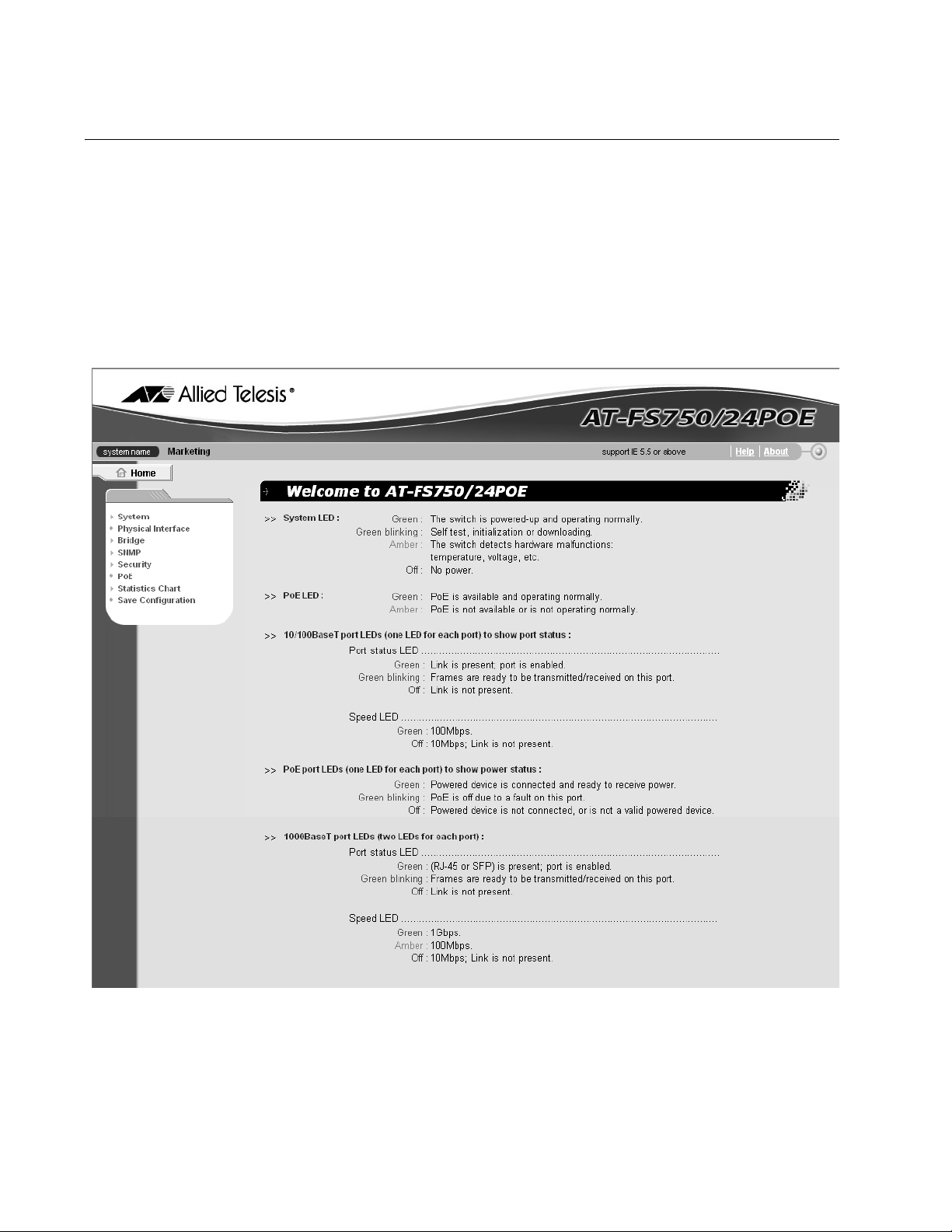
The main page for the AT-S88 management software is shown in
Figure 1.
Figure 1. Main Page
8
Page 17

AT-S88 Management Software User’s Guide
Note
Because the switch initially has no login or password protection,
Allied Telesis strongly suggests that you immediately do two things:
Change the IP address, as described in “Configuring the IP Address,
Subnet Mask, and Gateway Address” on page 12.
Add an administrative user and password who can access the
switch, as described in “Adding an Administrative User” on page 15.
9
Page 18

Chapter 1: Getting Started
Quitting a Management Session
To quit a management session, close the web browser.
10
Page 19

Chapter 2
Basic Switch Parameters
This chapter contains the following sections:
“Configuring the IP Address, Subnet Mask, and Gateway Address” on
page 12
“Enabling or Disabling DHCP” on page 14
“Configuring System Administration Information” on page 15
“Configuring the System Management Information” on page 18
“Setting Up IP Address Access” on page 20
“Rebooting the Switch” on page 23
“Returning the AT-S88 Management Software to the Default Values”
on page 24
11
Page 20
Chapter 2: Basic Switch Parameters
Configuring the IP Address, Subnet Mask, and Gateway Address
Warning
Be sure to record the switch’s IP address in a safe place. When you
change the switch’s IP address you lose your connection. Because
the AT-FS750/24POE Fast Ethernet Smart Switch does not have a
console port, your only means of managing the switch is through a
web browser, which requires that you have the switch’s IP address.
To configure the IP settings, perform the following procedure:
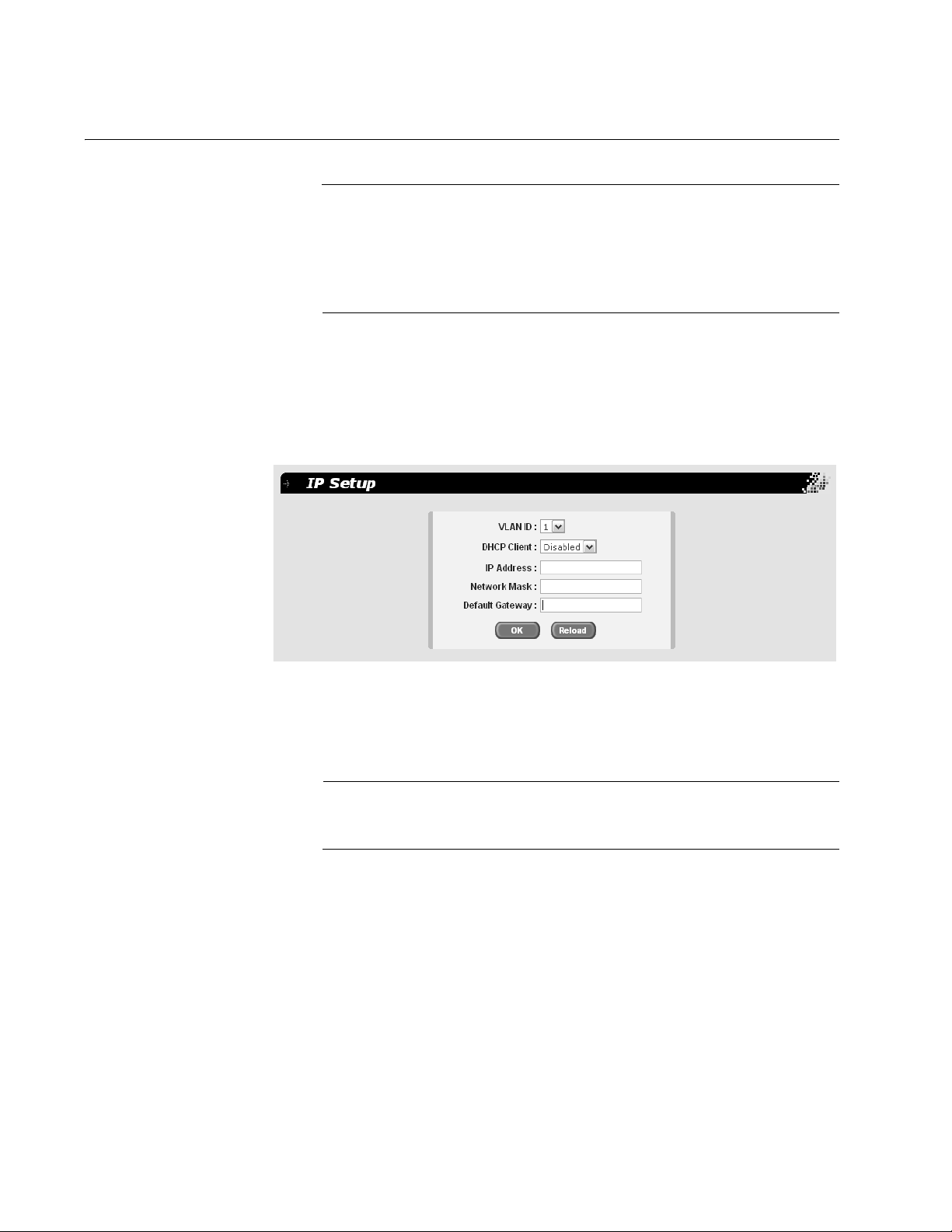
1. From the main menu, select System > IP Setup.
The IP Setup page is shown in Figure 2.
Figure 2. IP Setup Page
2. From the VLAN ID list, select the VLAN you want the switch to be a
part of.
Note
The default VLAN is 1. To create more VLANs, refer to Chapter 8,
”VLANs” on page 65.
3. In the IP Address field, enter an IP address for the switch.
4. In the Network Mask field, enter an IP address for the subnet mask.
5. In the Default Gateway field, enter the IP address of the default
gateway.
6. Click OK.
The settings are immediately implemented and you lose your
connection to the switch.
12
Page 21
AT-S88 Management Software User’s Guide
7. Log into the switch using its new IP address.
8. From the main menu, select Save Configuration.
The Save Configuration page is shown in Figure 3.
Figure 3. Save Configuration Page
Note
If you do not save your changes, they are discarded when you
reboot the switch.
9. Click Save.
For information about DHCP, see “Enabling or Disabling DHCP” on
page 14.
Warning
Be sure to record the switch’s IP address in a safe place. When you
change the switch’s IP address you lose your connection. Because
the switch does not have a console port, your only means of
managing the switch is through a web browser, which requires that
you have the switch’s IP address.
13
Page 22

Chapter 2: Basic Switch Parameters
Enabling or Disabling DHCP
To enable or disable the DHCP client, perform the following procedure:
1. From the main menu, select System > IP Setup.
The IP Setup Page is shown in Figure 2 on page 12.
2. From the DHCP Client list, choose Enabled or Disabled.
The default setting is disabled.
Note
If you lose connectivity after enabling DHCP or to determine the
switch’s new IP address in the future, use the SSM Utility. You can
access the utility in one of the following ways:
- Click the SSM Utility link on the AT-FS750/48 Fast Ethernet Switch
CD, and on the SSM Utility page, click the SSM Utility link.
- Download the SSM Utility files and documentation located in the
SSM Utility folder on the AT-FS750/48 Fast Ethernet Switch CD.
- Download the SSM Utility files and documentation from the Allied
Telesis website, www.alliedtelesis.com.
14
Page 23
Configuring System Administration Information
You can allow multiple users to access and administer the system by
adding their passwords to the system and/or set up password protection.
Note
When you start up the switch for the first time, you should add a user
to the system, protected by a password, who will be managing the
switch.
AT-S88 Management Software User’s Guide
Adding an
Administrative
User
To add an administrative user to the system, perform the following
procedure:
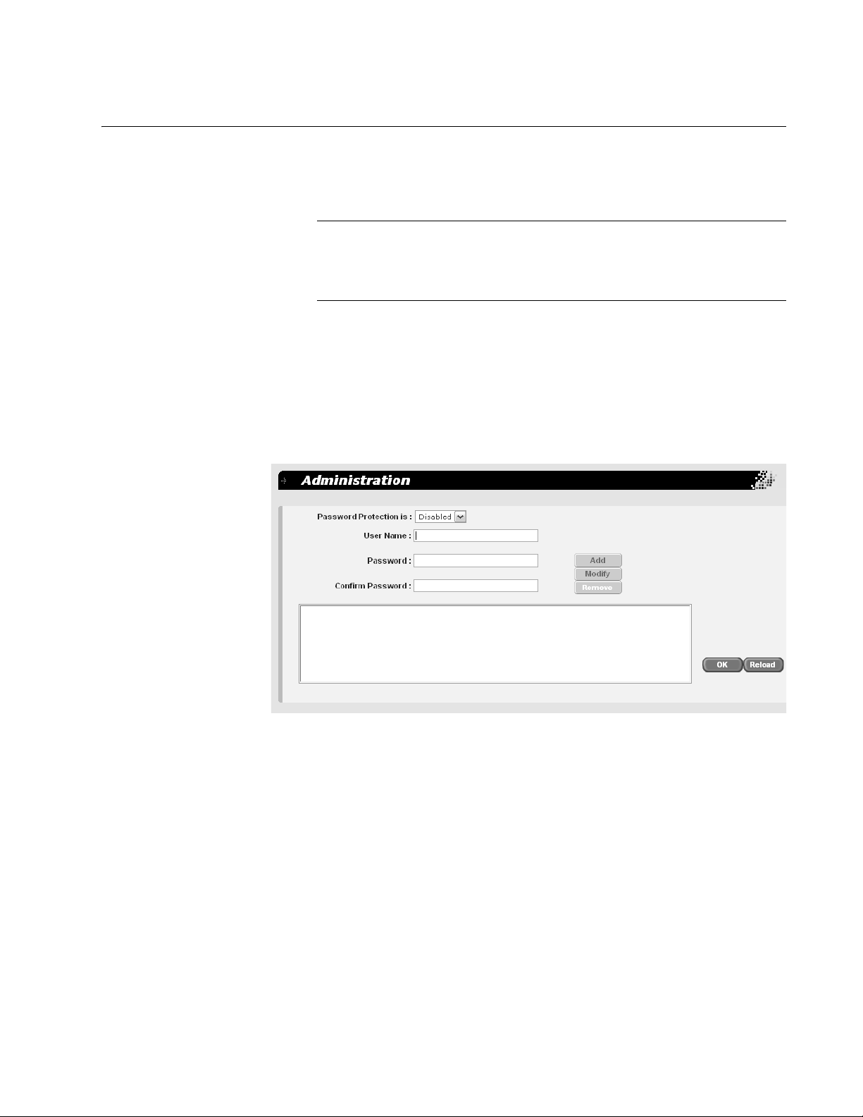
1. From the main menu, select System > Administration.
The Administration page is shown in Figure 4.
Figure 4. Administration Page
2. In the User Name field, type a name for the new administrative user.
3. In the Password field, type a password for the user, and re-type the
name in the Confirm Password field.
4. Do one of the following:
Click Add to add the user.
Click Reload to clear the fields and start over.
5. Click OK.
15
Page 24

Chapter 2: Basic Switch Parameters
6. To permanently save these settings in the configuration file, from the
main menu, select Save Configuration.
The Save Configuration page is shown in Figure 3 on page 13.
7. Click Save.
Modifying an
Administrative
User
To modify an administrative user on the system, perform the following
procedure:
1. From the main menu, select System > Administration.
The Administration page is shown in Figure 4 on page 15.
2. In the list of users, select the user whose information you want to
change.
The user name is displayed in the fields above.
3. To change the user’s name, in the User Name field, type a name for
the new administrative user.
4. To change the user’s password, in the Password field, type a new
password for the user, and re-type the name in the Confirm
Password field.
5. Do one of the following:
Click Modify to modify the user parameters.
Click Reload to clear the fields and start over.
6. Click OK.
7. To permanently save these settings in the configuration file, from the
main menu, select Save Configuration.
The Save Configuration page is shown in Figure 3 on page 13.
8. Click Save.
Deleting a User To remove a user from the system, perform the following procedure:
1. From the main menu, select System > Administration.
The Administration page is shown in Figure 4 on page 15.
2. In the list of users, select the user you want to delete.
3. Click Remove.
16
Page 25

AT-S88 Management Software User’s Guide
Note
Be careful not to delete all the users. You should have at least one
user, with a password, to manage the switch.
4. Click OK.
5. To permanently save these settings in the configuration file, from the
main menu, select Save Configuration.
The Save Configuration page is shown in Figure 3 on page 13.
6. Click Save.
Enabling or
Disabling
Password
Protection
To enable or disable password protection (authentication) for the users,
perform the following procedure:
1. From the main menu, select System > Administration.
The Administration page is shown in Figure 4 on page 15.
Note
Allied Telesis recommends that you keep password protection
enabled to protect the switch from unauthorized changes.
2. In the Password Protection list, select one of the following:
Enabled
To enable the feature.
Disabled
To disable password protection. This is the default.
3. Click OK.
4. To permanently save these settings in the configuration file, from the
main menu, select Save Configuration.
The Save Configuration page is shown in Figure 3 on page 13.
5. Click Save.
17
Page 26
Chapter 2: Basic Switch Parameters
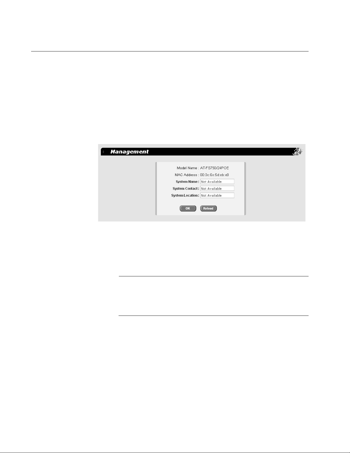
Configuring the System Management Information
This section explains how to assign a name to the switch, as well as
specify the location of the switch and the name of the switch’s
administrator. Entering this information is optional.
To set a switch’s management information, perform the following
procedure:
1. From the main menu, select System > Management.
The Management page is shown in Figure 5.
Figure 5. Management Page
2. In the System Name field, enter a name for the switch (for example,
Sales). The system name is optional and can contain up to 24
characters.
Note
Allied Telesis recommends that you assign a name to the switch. A
name helps you identify a switch when you manage it, and can also
help you avoid performing a configuration procedure on the wrong
switch.
3. In the System Contact field, enter the name of the network
administrator responsible for managing the switch. The contact name
is optional and can contain up to 24 characters.
4. In the System Location field, enter information to describe the
location of the switch (for example, Third Floor). The location is
optional and can contain up to 24 characters.
5. Do one of the following:
18
Click OK to save the system information.
Page 27

AT-S88 Management Software User’s Guide
Click Reload to clear the fields and start over.
6. To permanently save these settings in the configuration file, from the
main menu, select Save Configuration.
The Save Configuration page is shown in Figure 3 on page 13.
7. Click Save.
19
Page 28
Chapter 2: Basic Switch Parameters
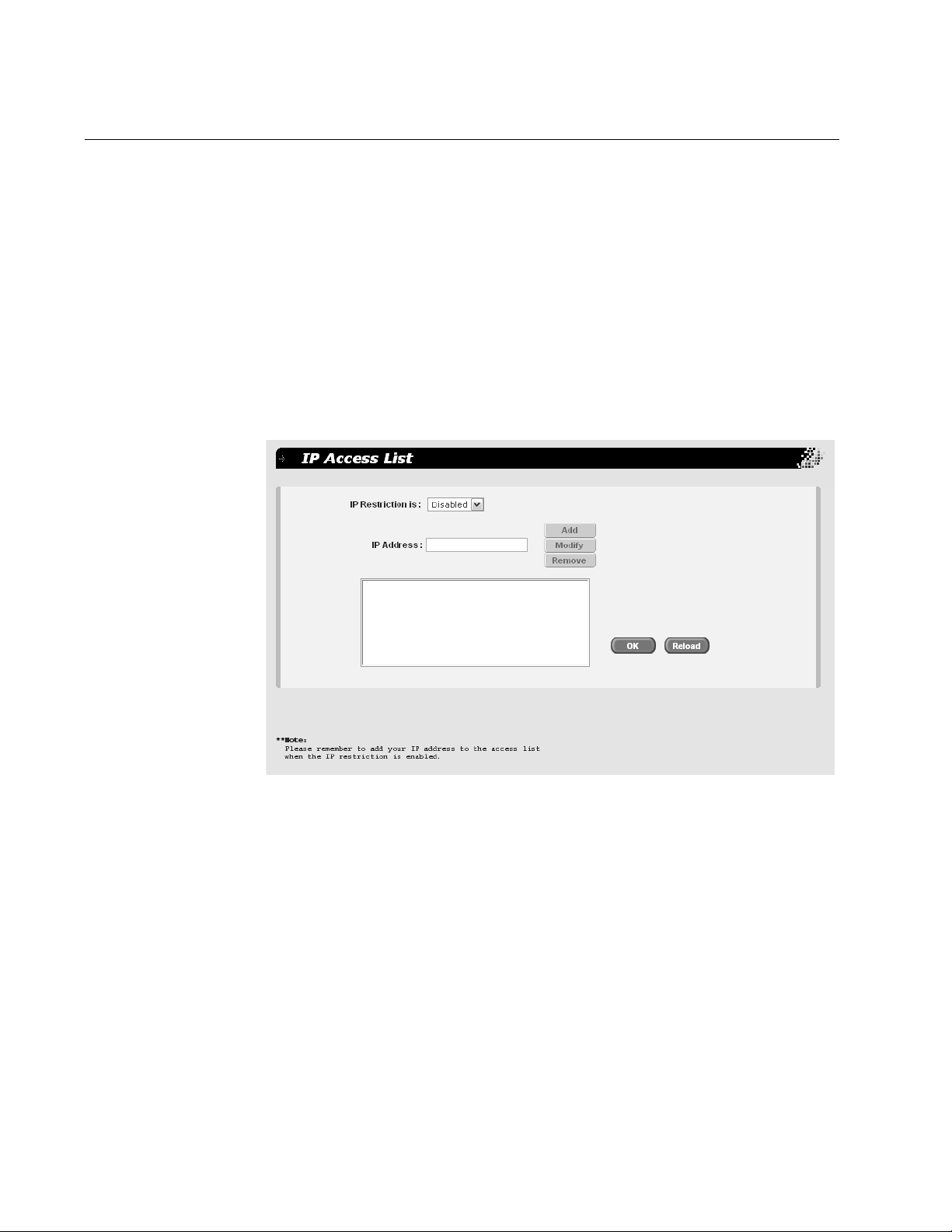
Setting Up IP Address Access
You can restrict remote management of the switch by creating an IP
access list. The switch uses the list to filter the management packets it
receives and accepts and processes only those packets that originate
from an IP address in the list. In addition to creating the list, you can
disable or enable the IP access list filtering.
Adding an IP
Address to the IP
Access List
To add an IP address to the IP access list, perform the following
procedure:
1. From the main menu, select System > IP Access List.
The IP Access List page is shown in Figure 6.
20
Figure 6. IP Access List Page
2. In the IP Address field, enter the IP address of the management
station to which you want to give access to the switch.
3. Click Add.
4. Do one of the following:
Click OK to save the IP address.
Click Reload to clear the fields and start over.
5. To permanently save these settings in the configuration file, from the
main menu, select Save Configuration.
The Save Configuration page is shown in Figure 3 on page 13.
Page 29

6. Click Save.
AT-S88 Management Software User’s Guide
Modifying an IP
Address in the IP
Access List
To modify an IP address in the IP access list, perform the following
procedure:
1. From the main menu, select System > IP Access List.
The IP Access List page is shown in Figure 6 on page 20.
2. In the IP address list, highlight the IP address you want to modify.
The address is displayed in the IP Address field.
3. In the IP Address field, modify the IP address.
4. Click Modify.
5. Do one of the following:
Click OK to save the modifications.
Click Reload to clear the fields and start over.
6. To permanently save these settings in the configuration file, from the
main menu, select Save Configuration.
The Save Configuration page is shown in Figure 3 on page 13.
Removing an IP
Address from the
IP Access List
7. Click Save.
To remove an IP address from the IP access list, perform the following
procedure:
1. From the main menu, select System > IP Access List.
The IP Access List page is shown in Figure 6 on page 20.
2. In the IP address list, select the IP address you want to remove.
3. Click Remove.
4. Click OK.
5. To permanently save these settings in the configuration file, from the
main menu, select Save Configuration.
The Save Configuration page is shown in Figure 3 on page 13.
6. Click Save.
21
Page 30

Chapter 2: Basic Switch Parameters
Enabling or
Disabling IP
Access
To enable or disable IP access for the users, perform the following
procedure:
1. From the main menu, select System > IP Access List.
The IP Access List page is shown in Figure 6 on page 20.
2. From the IP Restriction is list, choose one of the following:
Disabled - Disables IP restriction. This is the default.
Note
Before you enable IP access, remember to add your own IP address
to the list. Otherwise, you will not be able to access the switch.
Enabled - Enables IP restriction.
3. Click OK.
4. To permanently save these settings in the configuration file, from the
main menu, select Save Configuration.
The Save Configuration page is shown in Figure 3 on page 13.
5. Click Save.
22
Page 31

Rebooting the Switch
To reboot the switch, perform the following procedure:
1. From the main menu, select System > Reboot.
AT-S88 Management Software User’s Guide
Note
The reboot process stops network traffic and you lose your
connection to the switch.
This process also discards any configuration changes that you have
not permanently saved.
To permanently save any configuration changes, from the main
menu, select Save Configuration, and click Save before
proceeding.
The Reboot page is shown in Figure 7.
Figure 7. Reboot Page
2. Click Reboot.
23
Page 32

Chapter 2: Basic Switch Parameters
Returning the AT-S88 Management Software to the Default Values
To restore the management software to the factory default values, perform
the following procedure:
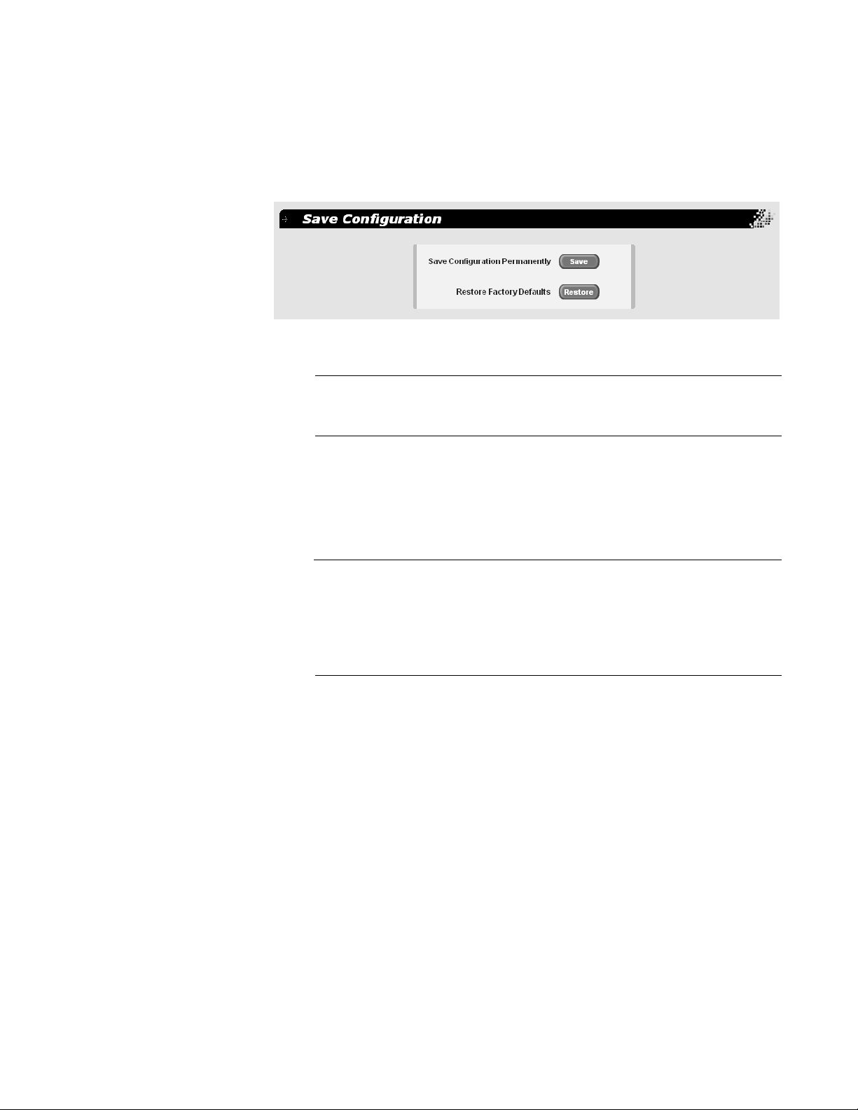
1. From the main menu, select Save Configuration.
The Save Configuration page is shown in Figure 8.
Figure 8. Save Configuration Page
Note
After the system defaults are restored, the switch is automatically
rebooted and you lose your connection to the switch.
Refer to “Starting a Management Session” on page 8 for information
about how to establish a new connection to the switch.
2. Click Restore to restore the factory defaults.
Note
The reboot process that occurs after the system defaults are
restored stops network traffic.
24
Page 33

Chapter 3
Port Configuration
This chapter contains the following procedures:
“Enabling or Disabling a Port” on page 26
“Setting a Port’s Speed and Duplex Mode” on page 27
“Enabling or Disabling Flow Control” on page 29
“Configuring Bandwidth Control” on page 30
25
Page 34

Chapter 3: Port Configuration
Enabling or Disabling a Port
To enable or disable a port, perform the following procedure:
1. From the main menu, select Physical Interface.
The Physical Interface page is shown in Figure 9.
Figure 9. Physical Interface Page
2. In the Port List, select the port you want to configure, or scroll through
the list below.
The port is highlighted in the port list.
3. In the Admin list, select Enabled or Disabled.
4. Click Modify.
The Admin status shown in the table for that port is changed. Continue
to select and modify other ports as necessary.
5. Do one of the following:
Click OK to save the changes.
Click Reload to clear the setting and start over.
6. To permanently save these settings in the configuration file, from the
main menu, select Save Configuration.
The Save Configuration page is shown in Figure 3 on page 13.
26
7. Click Save.
Page 35

Setting a Port’s Speed and Duplex Mode
To set the speed and duplex mode on the port, perform the following
procedure:
1. From the main menu, select Physical Interface.
The Physical Interface page is shown in Figure 9 on page 26.
2. In the Port List, select the port you want to configure, or scroll through
the list below.
The port is highlighted in the port list.
3. In the Mode list, select one of the following combinations of port speed
and duplex mode:
Auto - The port uses Auto-Negotiation to set its speed and duplex
mode. This is the default setting for all ports.
AT-S88 Management Software User’s Guide
10M-Half - 10 Mbps, half-duplex
10M-Full - 10 Mbps, full-duplex
100M-Half - 100 Mbps, half-duplex
100M-Full - 100 Mbps, full-duplex
1G-Full - 1 Gbps, full-duplex.
When a twisted pair port on the switch is set to Auto-Negotiation, the
default setting, the end node should also be using Auto-Negotiation to
prevent a duplex mode mismatch. A switch port using AutoNegotiation defaults to half-duplex if it detects that the end node is not
using Auto-Negotiation. This can result in a mismatch if the end node
is operating at a fixed duplex mode of full-duplex. To avoid this
problem when connecting an end node with a fixed duplex mode of
full-duplex to a switch port, disable Auto-Negotiation on the port and
set the port’s speed and duplex mode manually.
4. Click Modify.
The mode setting shown in the table for that port is changed. Continue
to select and modify other ports as necessary.
5. Do one of the following:
Click OK to save the changes.
Click Reload to clear the setting and start over.
27
Page 36

Chapter 3: Port Configuration
6. To permanently save these settings in the configuration file, from the
main menu, select Save Configuration.
The Save Configuration page is shown in Figure 3 on page 13.
7. Click Save.
28
Page 37

Enabling or Disabling Flow Control
A switch port uses flow control to control the flow of ingress packets from
its end node. Flow control applies only to ports operating in full-duplex
mode.
A port using flow control issues a special frame, referred to as a PAUSE
frame, as specified in the IEEE 802.3x standard, to stop the transmission
of data from an end node. When a port needs to stop an end node from
transmitting data, it issues this frame. The frame instructs the end node to
cease transmission. The port continues to issue PAUSE frames until it is
again ready to receive data from the end node.
The default setting for flow control on a switch port is disabled.
1. From the main menu, select Physical Interface.
The Physical Interface page is shown in Figure 9 on page 26.
AT-S88 Management Software User’s Guide
2. In the Port List, select the port you want to configure, or scroll through
the list below.
The port is highlighted in the port list.
3. In the Flow Control list, select Enabled or Disabled.
4. Click Modify.
The flow control setting shown in the table for that port is changed.
Continue to select and modify other ports as necessary.
5. Do one of the following:
Click OK to save the changes.
Click Reload to clear the settings and start over.
6. To permanently save these settings in the configuration file, from the
main menu, select Save Configuration.
The Save Configuration page is shown in Figure 3 on page 13.
7. Click Save.
29
Page 38

Chapter 3: Port Configuration
Configuring Bandwidth Control
If the performance of your network is affected by heavy traffic, you can use
bandwidth control to set the rate of various types of packets that a port
receives. You can control ingress packet types, including broadcast,
multicast, and Dlf packets or a combination of all three types, and limit
their rates. For egress packets, you can only configure the rate. (Dlf
packets are unicast packets that are broadcast because of a destination
address lookup failure.)
To configure bandwidth control, perform the following procedure:
1. From the main menu, select Bridge > Bandwidth Control.
The Bandwidth Control page is shown in Figure 10.
30
Figure 10. Bandwidth Control Page
2. In the Ingress Bandwidth Control section, do the following:
a. In the Port List, select the port you want to configure, or scroll
through the list below.
The port is highlighted in the port list.
Page 39

AT-S88 Management Software User’s Guide
b. In the Control list, select Enable to enable the control, or Disable
to disable it.
c. In the Mode list, select one of the following:
All
Affects broadcast, multicast, and Dlf packets.
Bcast
Controls only broadcast packets.
Bcast, Mcast
Limits broadcast and multicast packets.
Bcast, Mcast, Dlf
Limits broadcast, multicast, and Dlf packets.
d. In the Limit rate field, enter a number for the rate limit.
The range is 70 to 250,000 packets per second.
e. Click Modify.
3. In the Egress Bandwidth Control section, do the following:
a. In the Port List, select the port you want to configure, or scroll
through the list below.
The port is highlighted in the port list.
b. In the Control list, select Enable to enable the control, or Disable
to disable it.
c. In the Limit rate field, enter a number for the rate limit.
The range is 70 to 250,000 packets per second.
d. Click Modify.
4. Do one of the following:
Click OK to save the changes.
Click Reload to clear the settings and start over.
5. To permanently save these settings in the configuration file, from the
main menu, select Save Configuration.
The Save Configuration page is shown in Figure 3 on page 13.
6. Click Save.
31
Page 40

Chapter 3: Port Configuration
32
Page 41

Chapter 4
Power over Ethernet
Power over Ethernet (PoE) provides a way to distribute low-voltage power
across the network using existing Ethernet cable to a powered device
(PD). This allows the devices to operate without power adapters or AC
outlets. Powered devices include IP telephones, wireless LAN access
points, and surveillance cameras. Of the 24 ports on the AT-FS750/
24POE Fast Ethernet Smart Switch Switch, 12 are PoE-capable.
This chapter contains the following sections:
“PoE Overview” on page 34
“Viewing the PoE Status” on page 36
“Setting the Power Management Mode” on page 38
“Allocating Power to the PoE Ports” on page 40
“Diagnosing PoE Port Problems” on page 41
Section I: Basic Features 33
Page 42

Chapter 4: Power over Ethernet
PoE Overview
The twisted pair ports on the AT-FS750/24POE Fast Ethernet Smart
switch feature Power over Ethernet (PoE). PoE is a mechanism for
supplying power to network devices over the same twisted pair cables
used to carry network traffic. This feature can simplify network installation
and maintenance by allowing you to use the switch as a central power
source for other network devices.
A device that receives its power over an Ethernet cable is called a
powered device. Examples of such devices can be wireless access points,
IP telephones, webcams, and even other Ethernet switches. An example
of the latter is the unmanaged AT-FS705PD Ethernet switch from Allied
Telesis. A powered device connected to a port on the switch will receive
both network traffic and power over the same twisted pair cable.
The switch automatically determines whether a device connected to a port
is a powered device or not. A powered device has a signature resistor or
signature capacitor that the switch can detect over the Ethernet cabling. If
the resistor or capacitor is present, the switch assumes that the device is a
powered device.
Power Budgeting The AT-FS750/24POE Fast Ethernet Smart switch provides a maximum
of 15.4 W of power per port on six of the twelve ports for a total power
consumption of 95 W, while at the same time furnishing standard 10/100
Mbps Ethernet functionality. A port connected to a network node that is not
a powered device (that is, a device that receives its power from another
power source) functions as a regular Ethernet port, without PoE. The PoE
feature remains enabled on the port but no power is delivered to the
device.
You can allocate this power budget in one of two ways:
Maximum power (15.4 W) on each of 6 of the 12 PoE ports (Class 3)
Up to 7.3 W on all 12 PoE ports (Class 2)
Using the AT-S88 management software, you can enable or disable PoE
on a per-port basis and change the amount of power a port can receive.
The AT-S88 management software also allows you to prioritize the ports
in the event that there is not enough PoE power for all the powered
devices. This feature can help ensure that the most important powered
devices connected to the switch are guaranteed to have power.
The default setting for PoE on the switch is disabled at the port level.
Implementation A standard Ethernet twisted pair cable contains four pairs of strands for a
total of eight strands. 10/100 Mbps network traffic requires only four
34
Page 43

AT-S88 Management Software User’s Guide
strands, leaving four strands in the cable unused. The strands that carry
the network traffic are 1, 2, 3, and 6, and the spare strands are 4, 5, 7, and
8.
The IEEE 802.3af standard, which is the standard for PoE, describes two
modes for delivering power to the powered device over twisted pair
cabling. Mode A uses the same strands that carry the network traffic.
Mode B uses the spare strands. The PoE implementation on the
AT-FS750/24POE Fast Ethernet Smart switch is Mode B, where power is
transmitted over strands 4, 5, 7, and 8.
Powered devices that comply with the IEEE 802.3af standard typically
support both power delivery methods. So long as a powered device is
compliant with the standard, it should be able to receive its power from the
switch.
The PoE feature on the switch should also work with most legacy powered
devices as long as the device can be powered by pins 4, 5, 7, and 8. A
legacy device is a node that was manufactured before the IEEE 802.3af
standard was completed and, consequently, may not adhere to the
standard.
PoE Operation
Modes
You can configure the ports to operate in either an automation-based or
allocation-based mode.
When you select automation-based power operation, the power
management function automatically determines the amount of power to
allow for the device. The switch does this by detecting the device and
determining its PoE class, from 0 through 4. The PoE class specifies the
maximum input power level for the device.
If you select allocation-based power operation, you must configure the
power allocation for each PoE port, up to 20,000 mW.
You can also prioritize the ports in the event there is not be enough PoE
power for all the powered devices. This feature helps ensure that the most
important powered devices connected to the switch will be guaranteed
power.
35
Page 44

Chapter 4: Power over Ethernet
Viewing the PoE Status
To view information about the system’s PoE operation, perform the
following procedure:
1. From the main menu, select PoE.
The Power over Ethernet page is shown in Figure 11.
36
Figure 11. Power over Ethernet Page
The System Information section displays the following information
about the current status of PoE on the switch:
Voltage
The input voltage available.
Min Shutdown Voltage
The minimum total PoE voltage allowed before the PoE ports are shut
down.
Page 45

AT-S88 Management Software User’s Guide
Max Shutdown Voltage
The maximum total PoE voltage allowed before the PoE ports are shut
down.
Power Budget
The maximum amount of power available to all the PoE ports
combined.
Power Consumption
The number of watts of PoE power that is now being consumed or has
been allocated to the PoE ports.
Power Left
The number of watts of PoE power that is still available.
The Power Management Mode section is described in “Setting the Power
Management Mode” on page 38 and the Port Diagnosis section is
described in
37
Page 46

Chapter 4: Power over Ethernet
Setting the Power Management Mode
You can configure how the AT-FS750/24POE Fast Ethernet Smart Switch
allocates power to the PoE powered devices connected to the switch. The
two modes are automation-based and allocation-based.
When you select automation-based power operation, the power
management function automatically selects the mode of operation
according to how you configured the port itself.
If you select allocation-based power operation, you must manually
configure the power allocation for each PoE port, up to 20,000 mW.
To set the power management mode, perform the following procedure:
1. From the main menu, select PoE.
The Power over Ethernet page is shown in Figure 11 on page 36.
2. For the Power Mode, select one of the following:
Automation-based
The power management function automatically selects the amount of
power for each PoE port. You do not need to perform any other
configuration, however you MUST save the configuration for PoE
power to be applied to the port:
Allocation-based
You allocate how much power each port should receive.
If you chose allocation-based power budgeting, go on to step 9.
3. Click Modify.
4. Click OK.
5. From the main menu, select Save Configuration.
6. The Save Configuration page is shown in Figure 3 on page 13.
7. Click OK.
8. From the main menu, select PoE.
38
The Power over Ethernet page is shown in Figure 11 on page 36.
If you switched from one mode to the other, click Reload to refresh the
list of ports. When you switch from allocation-based to automationbased, the power allocations you made are not removed but have no
function.
Page 47

AT-S88 Management Software User’s Guide
9. In the Power Usage field, enter a number representing the percentage
of the total power budget of the switch that you want to allocate in total
for all the PoE ports (not for each individual PoE port).
Go on to “Allocating Power to the PoE Ports,” next, to perform the
power allocation for each port.
39
Page 48

Chapter 4: Power over Ethernet
Allocating Power to the PoE Ports
To allocate power to each PoE port, perform the following procedure:
1. From the main menu, select PoE.
The Power over Ethernet page is shown in Figure 11 on page 36.
2. In the Port Setting section, select a port from the Port list, or highlight
it in the table below.
3. To enable or disable a PoE port, from the Port State list, choose
Disable or Enable. The default is disable.
4. To set the port’s priority for receiving power in the event of some
power loss on the switch, select a number from the Priority list.
The lower the number that you select, the higher the port’s priority. If
you assign the same priority to more than one port, power is allocated
according to the physical order of the ports. For example, if you assign
priority 5 to ports 3 and 11, in the event of a power loss port 3 will get
available power and port 11 might not.
5. In the Allocation field, enter a number for the milliwats of power you
want that port to receive.
6. Click Modify.
7. Click OK.
8. Click Reload.
Note
You MUST save the configuration for PoE power to be applied to the
port.
9. From the main menu, select Save Configuration.
The Save Configuration page is shown in Figure 3 on page 13.
10. Click OK.
40
Page 49

Diagnosing PoE Port Problems
If the powered device on a PoE port appears to be operating abnormally,
you can perform a diagnostic test on the port to identify a potential
problem.
To perform port diagnosis, perform the following procedure:
1. From the main menu, select PoE.
The Power over Ethernet page is shown in Figure 11 on page 36.
2. In the Port Diagnosis section, select a port from the Port list and click
Query.
The Port Diagnosis section displays the current PoE status of the port,
an example of which is shown in Figure 12.
AT-S88 Management Software User’s Guide
Figure 12. Port Diagnosis Example
The port diagnosis information verifies whether or not the device
connected to that port is a valid powered device along with other
information about its power usage.
41
Page 50

Chapter 4: Power over Ethernet
42
Page 51

Chapter 5
SNMP
This chapter contains the following topics:
“SNMP Overview” on page 44
“Setting Up the SNMP Community Table” on page 46
“Setting Up the Host Table” on page 47
“Setting Up SNMP Trap Receivers” on page 49
43
Page 52

Chapter 5: SNMP
SNMP Overview
The Simple Network Management Program (SNMP) is another way for
you to manage the switch. This type of management involves viewing and
changing the management information base (MIB) objects on the device
using an SNMP application program. By default, SNMP is enabled on the
switch.
The procedures in this chapter show you how to create and manage
SNMP community strings through which your SNMP application program
at your management workstation can access the switch’s MIB objects.
To manage a switch using an SNMP application program, you must load
the Allied Telesis MIBs for the switch onto your management workstation
containing the SNMP application program. The MIBs are available from
the Allied Telesis web site at www.alliedtelesis.com.
To manage a switch using SNMP, you need to know the IP address of the
switch and at least one of the switch’s community strings. A community
string is a string of alphanumeric characters that gives you access to the
switch.
A community string has several attributes that you can use to control who
can use the string and what the string will allow a network management to
do on the switch. The community string attributes are defined below:
Community String Name
You must give the community string a name. The name can be from one
to 16 alphanumeric characters. Spaces are allowed.
Access Mode (Set)
This defines what the community string will allow a network manager to
do. There are two access modes: Read and Read/Write. A community
string with an access mode of Read can only be used to view but not
change the MIB objects on a switch. A community string with a Read/Write
access can be used to both view the MIB objects and change them.
Host Table
You can use this feature to control which management stations on your
network can use a community string. If you specify a host IP address for a
community string, then only those network managers working from
particular workstations can use it. A community string can have up to eight
IP addresses of management workstations assigned to it.
It is a good idea to assign host IP address to all community strings that
have a Read/Write access (Set) mode and then assign the IP addresses
of your management workstations to those strings. This helps reduce the
chance of someone gaining management access to a switch through a
community string and making unauthorized configuration changes.
44
Page 53

AT-S88 Management Software User’s Guide
Trap Receivers
A trap is a signal sent to one or more management workstations by the
switch to indicate the occurrence of a particular operating event on the
device. There are numerous operating events that can trigger a trap. For
instance, resetting the switch is an example of an occurrence that can
cause a switch to send a trap to the management workstations. You can
use traps to monitor activities on the switch.
Trap receivers are the devices, typically management workstations or
servers, that you want to receive the traps sent by the switch. You specify
the trap receivers by their IP addresses. You assign the IP addresses to
the community strings.
Each community string can have up to eight trap IP addresses.
It does not matter which community strings you assign your trap receivers.
When the switch sends a trap, it looks at all the community strings and
sends the trap to all trap receivers on all community strings. This is true
even for community strings that have a access mode of only Read.
Default SNMP
Community
Strings
If you are not interested in receiving traps, then you do not need to enter
any IP addresses of trap receivers.
The AT-S88 management software provides two default community
strings: public and private. The public string has an access mode of Read
Only and the private string has an access mode of Read/Write. If you
activate SNMP management on the switch, you change the status of the
private community string from open to closed to prevent unauthorized
changes to the switch.
45
Page 54

Chapter 5: SNMP
Setting Up the SNMP Community Table
To define the SNMP community names and their settings, perform the
following procedure:
1. From the main menu, select SNMP > Community Table.
The Community Table page is shown in Figure 13.
Figure 13. (SNMP) Community Table Page
2. To add a community name, enter it in one of the Community Name
fields.
3. To allow read/write access for any community name, click the
adjoining box in the Set column.
If you do not click Set for a particular community name, that
community name has read access only.
4. Do one of the following:
Click OK to save the community names.
Click Reload to clear the fields and start over.
5. To permanently save these settings in the configuration file, from the
main menu, select Save Configuration.
The Save Configuration page is shown in Figure 3 on page 13.
6. Click Save.
46
Page 55

Setting Up the Host Table
When you assign a host IP address to a community string, you identify
which management workstations can access the string. A community
string can have up to eight IP addresses of management workstations
(hosts) assigned to it.
To set up the host table, perform the following procedure:
1. From the main menu, select SNMP > Host Table.
The Host Table page is shown in Figure 14.
AT-S88 Management Software User’s Guide
Figure 14. (SNMP) Host Table Page
2. In the Host IP Address field, enter the IP address of a management
workstation
3. In the Community list, select the name of the SNMP community that
the host can access.
Continue to assign host addresses to the community strings you
configured.
4. Do one of the following:
Click OK to save the SNMP hosts.
Click Reload to clear the fields and start over.
5. To permanently save these settings in the configuration file, from the
main menu, select Save Configuration.
The Save Configuration page is shown in Figure 3 on page 13.
47
Page 56

Chapter 5: SNMP
6. Click Save.
48
Page 57

Setting Up SNMP Trap Receivers
To set up the SNMP trap receivers, perform the following procedure:
1. From the main menu, select SNMP > Trap Setting.
The Trap Setting page is shown in Figure 15.
AT-S88 Management Software User’s Guide
Figure 15. (SNMP) Trap Setting Page
2. In the Destination IP Address field, enter the IP address of the
management workstation where you want the traps sent.
3. In the Community for Trap field, enter the name of the community
that will receive the traps.
4. In the Trap Version list, choose v1 or v2c for SNMPv1 or SNMPv2c.
5. Do one of the following:
Click OK to save the trap settings.
Click Reload to clear the fields and start over.
6. To permanently save these settings in the configuration file, from the
main menu, select Save Configuration.
The Save Configuration page is shown in Figure 3 on page 13.
7. Click Save.
49
Page 58

Chapter 5: SNMP
50
Page 59

Chapter 6
Port Trunking
This chapter contains the following sections:
“Port Trunking Overview” on page 52
“Creating a Port Trunk” on page 54
“Modifying a Trunk” on page 56
“Removing a Trunk” on page 57
51
Page 60

Chapter 6: Port Trunking
Port Trunking Overview
A port trunk is an economical way for you to increase the bandwidth
between the Ethernet switch and another networking device, such as a
network server, router, workstation, or another Ethernet switch. A port
trunk is a group of ports that have been grouped together to function as
one logical path. A port trunk increases the bandwidth between the switch
and the other network device and is useful in situations where a single
physical link between the devices is insufficient to handle the traffic load.
Static Port Trunk
Overview
A static port trunk consists of two to eight ports on the switch that function
as a single virtual link between the switch and another device. A static port
trunk improves performance by distributing the traffic across multiple ports
between the devices and enhances reliability by reducing the reliance on a
single physical link.
A static trunk is easy to configure. You simply designate the ports on the
switch that are to be in the trunk and the management software on the
switch automatically groups them together.
The example in Figure 16 illustrates a static port trunk of four links
between two AT-FS750/24POE Fast Ethernet Smart Switches.
212223
9
11 13141516171819
PWR
POE
SYSTEM
PWR
SYSTEM
POE
1
3
24
1
24
5
8
7
8
14 16 18 20 22 24
10
12
13 15 17 19 21 23
9
11
14 16 18 20 22 24
10
12
10/100 PORTS
10/100 PORTS
6
10/100 POE PORTS
3
5
6
10/100 POE PORTS
10/100/1000Base-T
10/100/1000Base-T
CLASS 1
LASER PRODUCT
25
26
10/100/1000Base-T
SFP
UPLINK PORTS
CLASS 1
LASER PRODUCT
25
10/100/1000Base-T
SFP
UPLINK PORTS
13 15 17 19 21 23
9
11
7
1
SFP
2345678
26
1
SFP
2345678
10 12
9
11 13141516171819
10 12
25
AT-FS750/24POE
24 Port 10/100 Mbps WebSmart Switch
with 2 Combo Uplinks + 12 POE Ports
PORT ACTIVITY
LINK
ACT
100M
10M
PD ON
20
PD ERROR
24
26
1000M
100M
10M
1088
212223
25
AT-FS750/24POE
24 Port 10/100 Mbps WebSmart Switch
with 2 Combo Uplinks + 12 POE Ports
PORT ACTIVITY
LINK
ACT
100M
10M
PD ON
20
PD ERROR
24
26
1000M
100M
10M
1088
52
Figure 16. Static Port Trunk Example
Network equipment vendors tend to employ different techniques to
implement static trunks. Consequently, a static trunk on one device might
not be compatible with the same feature on a device from a different
manufacturer. For this reason static trunks are typically employed only
between devices from the same vendor. That is not to say that an Allied
Telesis layer 2 managed switch cannot form a static trunk with a device
from another manufacturer; but there is the possibility that the
implementations of static trunking on the two devices might not be
compatible.
Page 61

AT-S88 Management Software User’s Guide
Also note that a static trunk does not provide for redundancy or link
backup. If a port in a static trunk loses its link, the trunk’s total bandwidth is
diminished. Though the traffic carried by the lost link is shifted to one of the
remaining ports in the trunk, the bandwidth remains reduced until the lost
link is reestablished or you reconfigure the trunk by adding another port to
it.
Static Port Trunk Guidelines
Following are the guidelines for creating a static trunk:
Allied Telesis recommends using static port trunks between Allied
Telesis networking devices to ensure compatibility. While an Allied
Telesis device might be able to form a static trunk with a device from
another equipment vendor, there is the possibility that the
implementation of this feature on the two devices might not be
compatible, resulting in undesired switch behavior.
A static trunk can contain up to eight ports.
The ports of a static trunk must be of the same medium type. They can
be all twisted pair ports or all fiber optic ports.
The ports of a trunk can be either consecutive (for example Ports 5-9)
or nonconsecutive (for example, ports 4, 8, 11, 20).
Before creating a port trunk, examine the speed, duplex mode, flow
control, and back pressure settings of all of the ports that will be in the
trunk. Verify that the settings are the same for all ports in the trunk. If
these settings are not the same, then the switch will not allow you to
create the trunk.
After you have created a port trunk, a change to the speed, duplex
mode, flow control, or back pressure of any port in the trunk
automatically implements the same change on all the other member
ports.
A port can belong to only one static trunk at a time.
The ports of a static trunk can be untagged or untagged members of
the same VLAN.
The switch selects a port in the trunk to handle broadcast packets and
packets of unknown destination. The switch makes this choice based on a
hash algorithm, depending upon the source and destination MAC
addresses.
53
Page 62

Chapter 6: Port Trunking
Creating a Port Trunk
To create a port trunk, perform the following procedure:
1. From the main menu, select Bridge > Trunking.
The Trunking page is shown in Figure 17.
Figure 17. Trunking Page
2. In the Show Trunk list, select Add a New Trunk.
3. In the Name field, type a name for the trunk.
4. In the Trunk ID field, choose a number for the trunk ID, from 1 to 10.
5. Select the ports you want to include in the trunk by clicking the port
icon in the graphic image of the switch front.
A check mark is placed for each port you select, as for example
Figure 18.
54
Figure 18. Trunk Ports Selected
You can select up to a maximum of 8 ports for each trunk which must
all be within the same VLAN.
Page 63

AT-S88 Management Software User’s Guide
6. Do one of the following:
Click OK to save the trunk.
Click Reload to clear the trunk name and port selections and start
over.
7. To permanently save these settings in the configuration file, from the
main menu, select Save Configuration.
The Save Configuration page is shown in Figure 3 on page 13.
8. Click Save.
55
Page 64

Chapter 6: Port Trunking
Modifying a Trunk
To modify a port trunk, perform the following procedure:
1. From the main menu, select Bridge > Trunking.
The Trunking page is shown in Figure 17 on page 54.
2. In the Show Trunk list, select the trunk you want to modify.
3. Click OK.
The display is refreshed to show the trunk name you selected.
4. Select or de-select the ports you want to include in the trunk by clicking
the port icon in the graphic image of the switch front.
A check mark is placed for each port you select, as for example Figure
18 on page 54.
5. Do one of the following:
Click OK to save the trunk.
Click Reload to clear the changes and start over.
6. To permanently save these settings in the configuration file, from the
main menu, select Save Configuration.
The Save Configuration page is shown in Figure 3 on page 13.
7. Click Save.
56
Page 65

Removing a Trunk
AT-S88 Management Software User’s Guide
To remove a port trunk, perform the following procedure:
1. From the main menu, select Bridge > Trunking.
The Trunking page is shown in Figure 17 on page 54.
2. In the Show Trunk list, select the trunk you want to remove.
3. Check the Remove Trunk box.
4. Click OK.
5. To permanently save these settings in the configuration file, from the
main menu, select Save Configuration.
The Save Configuration page is shown in Figure 3 on page 13.
6. Click Save.
57
Page 66

Chapter 6: Port Trunking
58
Page 67

Chapter 7
Port Mirroring
This chapter describes port mirroring and contains the following topics:
“Port Mirroring Overview” on page 60
“Configuring Port Mirroring” on page 61
“Modifying a Port Mirror” on page 64
59
Page 68

Chapter 7: Port Mirroring
Port Mirroring Overview
The port mirroring feature allows you to unobtrusively monitor the traffic
being received and transmitted on one or more ports on a switch by
having the traffic copied to another switch port. You can connect a network
analyzer to the port where the traffic is being copied and monitor the traffic
on the other ports without impacting network performance or speed.
The port(s) whose traffic you want to mirror is called the source port(s).
The port where the traffic will be copied to is called the monitor port.
Observe the following guidelines when you create a port mirror:
You can select more than one source port at a time. However, the
more ports you mirror, the less likely the monitor port will be able to
handle all the traffic. For example, if you mirror the traffic of six heavily
active ports, the destination port is likely to drop packets, meaning that
it will not provide an accurate mirror of the traffic of the six source
ports.
The source and monitor ports must be located on the same switch.
You can mirror either the ingress or egress traffic of the source ports,
or both.
60
Page 69

Configuring Port Mirroring
To configure port mirroring, perform the following procedure:
1. From the main menu, select Bridge > Mirroring.
The Mirroring page is shown in Figure 19.
AT-S88 Management Software User’s Guide
Figure 19. Mirroring Page
2. Select the ports whose ingress traffic you want to monitor by clicking
the port icon in the graphic image of the switch front at the top of the
page.
61
Page 70

Chapter 7: Port Mirroring
A check mark is placed for each port you select, as for example
Figure 20.
Figure 20. Ingress Ports Selected
3. Select the ports whose egress traffic you want to monitor by clicking
the port icon in the graphic image of the switch front at the top of the
page.
A check mark is placed for each port you select, as for example
Figure 21.
62
Figure 21. Egress Ports Selected
4. In the Monitor Port list, select the port to which the traffic will be sent.
Page 71

AT-S88 Management Software User’s Guide
5. In the Mirror Mode list, select Enable.
6. Do one of the following:
Click OK to save the port mirror.
Click Reload to clear the port mirror and start over.
7. To permanently save these settings in the configuration file, from the
main menu, select Save Configuration.
The Save Configuration page is shown in Figure 3 on page 13.
8. Click Save.
63
Page 72

Chapter 7: Port Mirroring
Modifying a Port Mirror
To modify a port mirror, perform the following procedure.
1. From the main menu, select Bridge > Mirroring.
The Mirroring page is shown in Figure 19 on page 61
2. Select or de-select the ports whose ingress traffic you want to monitor
by clicking the port icon in the graphic image of the switch front at the
top of the page.
3. Select or de-select the ports whose egress traffic you want to monitor
by clicking the port icon in the graphic image of the switch front at the
top of the page.
4. In the Monitor Port list, select the port to which the traffic will be sent,
if you want to change that.
5. In the Mirror Mode list, select Enable.
6. Do one of the following:
Click OK to save the port mirror.
Click Reload to clear the port mirror and start over.
7. To permanently save these settings in the configuration file, from the
main menu, select Save Configuration.
The Save Configuration page is shown in Figure 3 on page 13.
8. Click Save.
64
Page 73

Chapter 8
VLANs
This chapter about VLANs contains the following sections:
“VLAN Overview” on page 66
“Port-based VLAN Overview” on page 68
“Tagged VLAN Overview” on page 69
“Creating a Port-Based VLAN” on page 71
“Creating a Tagged VLAN” on page 74
“Changing a Port’s VLAN Mode” on page 78
65
Page 74

Chapter 8: VLANs
VLAN Overview
A VLAN is a group of ports on an Ethernet switch that form a logical
Ethernet segment. The ports of a VLAN form an independent traffic
domain where the traffic generated by the nodes of a VLAN remains within
the VLAN.
With VLANs, you can segment your network through the switch’s AT-S88
management software and so be able to group nodes with related
functions into their own separate, logical LAN segments. These VLAN
groupings can be based on similar data needs or security requirements.
For example, you could create separate VLANs for the different
departments in your company, such as one for Sales and another for
Accounting.
VLANs offer several important benefits:
Improved network performance
Network performance often suffers as networks grow in size and as
data traffic increases. The more nodes on each LAN segment vying for
bandwidth, the greater the likelihood overall network performance
decreases.
VLANs improve network perform because VLAN traffic stays within the
VLAN. The nodes of a VLAN receive traffic only from nodes of the
same VLAN. This reduces the need for nodes to handle traffic not
destined for them. It also frees up bandwidth within all the logical
workgroups.
In addition, because each VLAN constitutes a separate broadcast
domain, broadcast traffic remains within the VLAN. This too can
improve overall network performance.
Increased security
Because data traffic generated by a node in a VLAN is restricted only
to the other nodes of the same VLAN, you can use VLANs to control
the flow of packets in your network and prevent packets from flowing
to unauthorized end nodes.
Simplified network management
VLANs can also simplify network management. Before the advent of
VLANs, physical changes to the network often had to been made at
the switches in the wiring closets. For example, if an employee
changed departments, changing the employee’s LAN segment
assignment might require a change to the wiring at the switches.
66
But with VLANS, you can change the LAN segment assignment of an
end node connected to the switch through the switch’s AT-S88
Page 75

AT-S88 Management Software User’s Guide
management software. You can change the VLAN memberships
through the management software without moving the workstations
physically, or changing group memberships by moving cables from
one switch port to another.
In addition, a virtual LAN can span more than one switch. This means
that the end nodes of a VLAN do not need to be connected to the
same switch and so are not restricted to being in the same physical
location.
The AT-FS750/24POE Fast Ethernet Smart Switch supports the following
types of VLANs you can create yourself:
Port-based VLANs
Tagged VLANs
These VLANs are described in the following sections.
67
Page 76

Chapter 8: VLANs
Port-based VLAN Overview
As explained in “VLAN Overview” on page 66, a VLAN consists of a group
of ports on an Ethernet switch that form an independent traffic domain.
Traffic generated by the end nodes of a VLAN remains within the VLAN
and does not cross over to the end nodes of other VLANs unless there is
an interconnection device, such as a router or Layer 3 switch.
A port-based VLAN is a group of ports on a Gigabit Ethernet Switch that
form a logical Ethernet segment.
A port-based VLAN can have as many or as few ports as needed. The
VLAN can consist of all the ports on an Ethernet switch, or just a few ports.
The parts of a port-based VLAN in the AT-S88 management software are:
VLAN name
Group ID
VLAN Name To create a port-based VLAN, you must give it a name. The name should
reflect the function of the network devices that are be members of the
VLAN. Examples include Sales, Production, and Engineering.
Group ID Each VLAN in a network must have a unique number assigned to it. This
number is called the Group ID. This number uniquely identifies a VLAN in
the switch.
Each port of a port-based VLAN can belong to as many VLANs as
needed. Therefore, traffic can be forwarded to the members of the groups
to which the port is assigned. For example, port 1 and port 2 are members
of group 1 and ports 1 and 3 are members of group 2. In this case, traffic
from port 1 is forwarded to ports 2 and 3, traffic from port 2 is forwarded
only to port 1, and traffic from port 3 is forwarded only to port 1.
General Rules for
Creating a Port-
based VLAN
Below is a summary of the general rules to observe when creating a portbased VLAN.
Each port-based VLAN must be assigned a name.
Each port-based VLAN must be assigned to one or more Group IDs. If
a particular VLAN spans multiples switches, each part of the VLAN on
the different switches should be assigned the same Group ID.
68
A port-based VLAN that spans multiple switches requires a port on
each switch where the VLAN is located to function as an
interconnection between the switches.
An AT-FS750/24POE Fast Ethernet Smart Switch switch can support
up to 256 port-based VLANs.
Page 77

Tagged VLAN Overview
The second type of VLAN supported by the AT-S88 management software
is the tagged VLAN. VLAN membership in a tagged VLAN is determined
by information within the frames that are received on a port and the VLAN
configuration of each port.
The VLAN information within an Ethernet frame is referred to as a tag or
tagged header. A tag, which follows the source and destination addresses
in a frame, contains the VLAN ID of the VLAN to which the frame belongs
(IEEE 802.3ac standard). This number uniquely identifies each VLAN in a
network.
When a switch receives a frame with a VLAN tag, referred to as a tagged
frame, the switch forwards the frame only to those ports whose VLAN ID
equals the VLAN tag.
A port to receive or transmit tagged frames is referred to as a tagged port.
Any network device connected to a tagged port must be IEEE 802.1Qcompliant. This is the standard that outlines the requirements and
standards for tagging. The device must be able to process the tagged
information on received frames and add tagged information to transmitted
frames.
AT-S88 Management Software User’s Guide
Tagged and
Untagged Ports
The parts of a tagged VLAN are:
VLAN Name
Group ID (VLAN ID)
Tagged and Untagged Ports
Port VLAN identifier (PVID)
When you specify that a port is a member of a tagged VLAN, you need to
specify that it is tagged or untagged. You can have a combination of
tagged and untagged ports in the same VLAN.
Packet transmission from a tagged port differs from packet transmission
from an untagged port. When a packet is transmitted from a tagged port,
the tagged information within the packet is maintained when it is
transmitted to the next network device. If the packet is transmitted from an
untagged port, the VLAN tag information is removed from the packet
before it is transmitted to the next network device.
The IEEE 802.1Q standard describes how the tagging information within a
packet is used to forward the traffic throughout the switch. The handling of
packets tagged with a VLAN ID coming into a port is straightforward, If the
incoming packet’s VLAN tag matches one of the VLAN IDs of which the
port is a member, the packet is accepted and forwarded to the appropriate
port(s) within that VLAN. If the incoming packet’s VLAN tag does not
69
Page 78

Chapter 8: VLANs
match one of the VLAN IDs assigned to the port, the packet is discarded.
Port VLAN
Identifier
General Rules for
Creating a
Tagged VLAN
When an untagged packet is received on a port in a tagged VLAN, it is
assigned to one of the VLANs of which that port is a member. The
deciding factor in this process is the Port VLAN Identifier (PVID). Both
tagged and untagged ports in a tagged VLAN must have a PVID assigned
to them. The default value of the PVID for each port is 1. The switch
associates a received untagged packet to the VLAN ID that matches the
PVID assigned to the port. As a result, the packet is only forwarded to
those ports that are members of that VLAN.
Below is a summary of the rules to observe when you create a tagged
VLAN.
Each tagged VLAN must be assigned a unique VID. If a particular
VLAN spans multiple switches, each part of the VLAN on the different
switches must be assigned the same VID.
A tagged port can be a member of multiple VLANs.
An AT-FS750/24POE Fast Ethernet Smart Switch can support up to
26 tagged VLANS.
70
Page 79

Creating a Port-Based VLAN
This section contains the following procedures:
“Creating a Port-Based VLAN”, next
“Modifying a Port-Based VLAN” on page 72
“Viewing a Port-Based VLAN” on page 73
The default setting on the switch is for all ports to be untagged members of
the default VLAN (VLAN ID 1).
AT-S88 Management Software User’s Guide
Creating a Port-
Based VLAN
To create a port-based VLAN, perform the following procedure:
1. From the main menu, select Bridge > VLAN > Port-Based VLAN.
The Port-Based VLAN page is shown in Figure 22. Because the
default VLAN is a tagged VLAN, this page automatically displays the
Add a new VLAN selection.
Figure 22. Port-Based VLAN Page
2. In the Name field, type a name for the new VLAN.
3. In the Group ID field, type a number for the Group ID you want to
associate with this VLAN. The range is 1 to 26.
4. Select the ports you want to include in the VLAN by clicking the port
icon in the graphic image of the switch front.
71
Page 80

Chapter 8: VLANs
A check mark is placed for each port you select, as for example
Figure 23.
Figure 23. Port-based VLAN Ports Selected
5. Or, click Attach All to select all of the ports to include in the VLAN.
Modifying a Port-
Based VLAN
6. Do one of the following:
Click OK to save the VLAN.
Click Reload to clear the VLAN and start over.
7. To permanently save these settings in the configuration file, from the
main menu, select Save Configuration.
The Save Configuration page is shown in Figure 3 on page 13.
8. Click Save.
To modify a port-based VLAN, perform the following procedure:
1. From the main menu, select Bridge > VLAN > Port-Based VLAN.
The Port-Based VLAN page is shown in Figure 22 on page 71.
2. In the Show Port-Based VLAN list, select the VLAN you want to
modify.
The graphic image of the switch is updated to show the ports that are
included in this VLAN.
72
3. Do one of the following:
Click a port to add it to or remove it from the VLAN.
Click Detach All to remove all the ports from the VLAN and start
over.
Click Attach All to add all the ports to the VLAN and then
Page 81

AT-S88 Management Software User’s Guide
selectively click the ones you do not want included.
4. Do one of the following:
Click OK to save the changes.
Click Reload to clear the changes and start over.
5. To permanently save these settings in the configuration file, from the
main menu, select Save Configuration.
The Save Configuration page is shown in Figure 3 on page 13.
6. Click Save.
Viewing a Port-
Based VLAN
To view a port-based VLAN, perform the following procedure:
1. From the main menu, select Bridge > VLAN > Port-Based VLAN.
The Port-Based VLAN page is shown in Figure 22 on page 71.
2. In the Show Port-Based VLAN list, select the VLAN you want to view.
The graphic image of the switch is updated to show the ports that are
included in this VLAN.
73
Page 82

Chapter 8: VLANs
Creating a Tagged VLAN
This section contains the following procedures:
“Creating a Tagged VLAN”, next
“Modifying a Tagged VLAN” on page 76
“Viewing a Tagged VLAN” on page 77
The switch’s default setting is for all ports to be untagged members of the
default VLAN (VLAN ID 1).
Creating a
Tagged VLAN
To create a tagged VLAN, perform the following procedure:
1. From the main menu, select Bridge > VLAN > Tagged VLAN.
The Tagged VLAN page is shown in Figure 24.This page shows the
default tagged VLAN, with all ports identified as untagged ports.
Figure 24. Tagged VLAN Page
2. In the Show VLAN list, select Add a new VLAN.
74
Page 83

AT-S88 Management Software User’s Guide
The page is refreshed to show the ports without any designations and
other parameters you need to define to create the tagged VLAN, as
shown in Figure 25.
Figure 25. Add Tagged VLAN Page
3. In the Name field, type a name for the new VLAN.
4. In the VLAN ID field, type a number for the ID you want to associate
with this VLAN. The range is 1 to 4000.
5. In the Name field, type a name for this VLAN.
6. Select the ports you want to include in the VLAN by clicking the port
icon in the graphic image of the switch front. Do one or more of the
following:
Click Attach All to attach all the ports to the VLAN as tagged ports,
and then modify the designations by clicking the ports.
Click once to assign the port as a tagged member of the VLAN. A
“T” is placed on that port.
Click twice to assign the port as an untagged member of the VLAN.
A “U” is placed on that port
75
Page 84

Chapter 8: VLANs
Figure 26 shows an example of a tagged VLAN with the ports
selected.
Figure 26. Tagged VLAN Ports Selected
7. To start over, click Detach All remove all the ports from the VLAN.
Modifying a
Tagged VLAN
8. Do one of the following:
Click OK to save the VLAN.
Click Reload to reload any previous settings for the VLAN.
9. To permanently save these settings in the configuration file, from the
main menu, select Save Configuration.
The Save Configuration page is shown in Figure 3 on page 13.
10. Click Save.
To modify a tagged VLAN, perform the following procedure:
1. From the main menu, select Bridge > VLAN > Tagged VLAN.
The Tagged VLAN page is shown in Figure 24 on page 74.
2. In the Show VLAN list, select the VLAN you want to modify.
The graphic image of the switch is updated to show the ports that are
included in this VLAN.
3. Do one of the following:
76
Click Attach All to attach all the ports to the VLAN as tagged
ports, and then modify the designations by clicking the ports.
Click once to assign the port as a tagged member of the VLAN. A
“T” is placed on that port.
Page 85

AT-S88 Management Software User’s Guide
Click twice to assign the port as an untagged member of the VLAN.
A “U” is placed on that port
Click Detach All to remove all the ports from the VLAN and start
over.
4. Do one of the following:
Click OK to save the changes.
Click Reload to reload any previous settings for the VLAN.
5. To permanently save these settings in the configuration file, from the
main menu, select Save Configuration.
The Save Configuration page is shown in Figure 3 on page 13.
6. Click Save.
Viewing a Tagged
VLAN
To view a tagged VLAN, perform the following procedure:
1. From the main menu, select Bridge > VLAN > Tagged VLAN.
The Tagged VLAN page is shown in Figure 24 on page 74.
2. In the Show VLAN list, select the VLAN you want to view.
The graphic image of the switch is updated to show the ports that are
included in this VLAN.
77
Page 86

Chapter 8: VLANs
Changing a Port’s VLAN Mode
The switch can operate in only one VLAN mode at a time: tagged VLAN
mode (802.1Q), or port-based VLAN mode.
To change the VLAN mode of a port on the switch, perform the following
procedure:
1. From the main menu, select Bridge > VLAN > VLAN Mode.
The VLAN Mode page is shown in Figure 27.
Figure 27. VLAN Mode Page
2. In the Port List, select the port you want to configure, or scroll through
the list below.
The port is highlighted in the port list.
3. From the VLAN Mode list, select either 802.1Q Tagged VLAN or
Port-Based VLAN. The default is 802.1Q tagged VLAN mode.
Note
The default VLAN mode is 802.1Q Tagged VLAN.
4. To view the ports that are set to a particular mode, in the VLAN Mode
list, select the type of VLAN you want to view, either
5. Click Modify.
6. Do one of the following:
Click OK to save the changes.
Click Reload to reload the previous configurations.
78
Page 87

AT-S88 Management Software User’s Guide
7. To permanently save these settings in the configuration file, from the
main menu, select Save Configuration.
The Save Configuration page is shown in Figure 3 on page 13.
8. Click Save.
79
Page 88

Chapter 8: VLANs
80
Page 89

Chapter 9
Class of Service (CoS)
This chapter contains the following topics:
“CoS Overview” on page 82
“Configuring CoS” on page 86
“Mapping CoS Priorities to Egress Queues” on page 88
“Specifying the Scheduling Algorithm” on page 89
81
Page 90

Chapter 9: Class of Service (CoS)
CoS Overview
When a port on an Ethernet switch becomes oversubscribed—its egress
queues contain more packets than the port can handle in a timely
manner—the port may be forced to delay the transmission of some
packets, resulting in the delay of packets reaching their destinations. A
port may be forced to delay transmission of packets while it handles other
traffic, and, in some situations, some packets destined to be forwarded to
an oversubscribed port from other switch ports may be discarded.
Minor delays are often of no consequence to a network or its performance.
But there are applications, referred to as delay or time sensitive
applications, that can be impacted by packet delays. Voice transmission
and video conferences are two examples. If packets carrying data for
either of these are delayed from reaching their destination, the audio or
video quality may suffer.
This is where CoS is of value. It allows you to manage the flow of traffic
through a switch by having the switch ports give higher priority to some
packets, such as delay sensitive traffic, over other packets. This is
referred to as prioritizing traffic.
CoS applies primarily to tagged packets. A tagged packet, as explained in
“Tagged VLAN Overview” on page 69, contains information within it that
specifies the VLAN to which the packet belongs.
A tagged packet can also contain a priority level. This priority level is used
by network switches and other networking devices to know how important
(delay sensitive) that packet is compared to other packets. Packets of a
high priority are typically handled before packets of a low priority.
CoS, as defined in the IEEE 802.1p standard, has eight levels of priority.
The priorities are 0 to 7, with 0 the lowest priority and 7 the highest.
When a tagged packet is received on a port on the switch, it is examined
by the AT-S88 software for its priority. The switch software uses the
priority to determine which egress priority queue the packet should be
directed to on the egress port.
Each switch port has four egress queues, labeled Q1, Q2, Q3, and Q4. Q1
is the lowest priority queue and Q4 is the highest. A packet in a high
priority egress queue is typically transmitted out a port sooner than a
packet in a low priority queue.
Table 1 lists the default mappings between the eight CoS priority levels
82
Page 91

AT-S88 Management Software User’s Guide
and the four egress queues of a switch port.
Table 1. Default Mappings of IEEE 802.1p Priority Levels to Priority
Queues
IEEE 802.1p Priority
Level
Port Priority Queue
0Q2
1Q1
2Q1
3Q2
4Q3
5Q3
6Q4
7Q4
For example, if a tagged packet with a priority level of 3 entered a port on
the switch, the switch would store the packet in Q2 queue on the egress
port.
Note that priority 0 is mapped to CoS queue 2 instead of CoS queue 1
because tagged traffic that has never been prioritized has a VLAN tag
User Priority of 1. If priority 0 was mapped to CoS queue 1, this default
traffic goes to the lowest queue, which is probably undesirable. This
mapping also makes it possible to give some traffic a lower priority than
the default traffic.
You can change these mappings. For example, you might decide that
packets with a priority of 5 need to be handled by egress queue Q3 and
packets with a priority of 2 should be handled in Q1. The result is shown in
Table 2.
Table 2. Customized Mappings of IEEE 802.1p Priority Levels to Priority
Queues
IEEE 802.1p Priority
Level
Port Priority Queue
0Q2
1Q1
2Q1
3Q3
4Q3
83
Page 92

Chapter 9: Class of Service (CoS)
Table 2. Customized Mappings of IEEE 802.1p Priority Levels to Priority
Queues (Continued)
IEEE 802.1p Priority
Level
Port Priority Queue
5Q3
6Q4
7Q4
The procedure for changing the default mappings is found in “Mapping
CoS Priorities to Egress Queues” on page 88. Note that because all ports
must use the same priority-to-egress queue mappings, these mappings
are applied at the switch level. They cannot be set on a per-port basis.
CoS relates primarily to tagged packets rather than untagged packets
because untagged packets do not contain a priority level. By default, all
untagged packets are placed in a port’s Q1 egress queue, the queue with
the lowest priority. You can change this mapping, as described in
“Mapping CoS Priorities to Egress Queues” on page 88.
One last thing to note is that the AT-S88 software does not change the
priority level in a tagged packet. The packet leaves the switch with the
same priority it had when it entered. This is true even if you change the
default priority-to-egress queue mappings.
Scheduling A switch port needs a mechanism for knowing the order in which it should
handle the packets in its four egress queues. For example, if all the
queues contain packets, should the port transmit all packets from Q3, the
highest priority queue, before moving on to the other queues, or should it
instead just do a few packets from each queue and, if so, how many?
This control mechanism is referred to as the scheduling algorithm.
Scheduling determines the order in which a port handles the packets in its
egress queues. The AT-S88 software has two types of scheduling:
Strict priority
Weighted round robin priority
To specify the scheduling, refer to “Mapping CoS Priorities to Egress
Queues” on page 88.
Note
Scheduling is set at the switch level. You cannot set this on a perport basis.
Strict Priority Scheduling
84
Page 93

AT-S88 Management Software User’s Guide
With this type of scheduling, a port transmits all packets out of higher
priority queues before transmitting any from the lower priority queues. For
instance, as long as there are packets in Q3 it does not handle any
packets in Q2.
The value to this type of scheduling is that high priority packets are always
handled before low priority packets.
The problem with this method is that some low priority packets might never
be transmitted out the port because a port might never get to the low
priority queues. A port handling a large volume of high priority traffic may
be so busy transmitting the high priority packets that traffic that it never
has an opportunity to get to any packets that are stored in its low priority
queues.
Weighted Round Robin Priority Scheduling
The weighted round robin (WRR) scheduling method functions as its name
implies. The port transmits a set number of packets from each queue, in a
round robin fashion, so that each has a chance to transmit traffic. This
method guarantees that every queue receives some attention from the
port for transmitting packets.
Table 3 shows the WRR factory default settings for the number of packets
transmitted from each queue.
Table 3. Example of Weighted Round Robin Priority
Port Egress Queue
Maximum Number of
Packets
Q3 8
Q2 4
Q1 2
Q0 1
85
Page 94

Chapter 9: Class of Service (CoS)
Configuring CoS
To configure CoS, perform the following procedure:
1. From the main menu, select Bridge > Default Port VLAN & COS.
The Default Port VLAN & CoS page is shown in Figure 28.
Figure 28. Default Port VLAN & CoS Page
2. In the Port List, select the port you want to configure, or scroll through
the list below.
The port is highlighted in the port list.
3. Select the PVID of the VLAN that the port is associated with.
For more information about the PVID, refer to “Port VLAN Identifier” on
page 70;
4. In the CoS Value list, select a CoS value, from 0 through 7.
5. Click Modify.
The port settings in the table are changed. Continue to select and
modify additional ports.
6. Do one of the following:
Click OK to save the changes.
Click Reload to retrieve the previous settings.
86
7. To permanently save these settings in the configuration file, from the
main menu, select Save Configuration.
The Save Configuration page is shown in Figure 3 on page 13.
Page 95

8. Click Save.
AT-S88 Management Software User’s Guide
87
Page 96

Chapter 9: Class of Service (CoS)
Mapping CoS Priorities to Egress Queues
This procedure explains how to change the default mappings of CoS
priorities to egress priority queues, shown in Table 3 on page 85. This is
set at the switch level. You cannot set this at the per-port level.
To change the CoS priority mappings, perform the following procedure.
1. From the main menu, select Bridge > CoS.
The CoS page is shown in Figure 29.
88
Figure 29. CoS Page
2. For each priority whose queue you want to change, select a queue in
the CoS Queue list.
3. Do one of the following:
Click OK to save the changes.
Click Reload to clear the changes and start over.
4. To permanently save these settings in the configuration file, from the
main menu, select Save Configuration.
The Save Configuration page is shown in Figure 3 on page 13.
5. Click Save.
Page 97

Specifying the Scheduling Algorithm
To change the scheduling algorithm, perform the following procedure.
1. From the main menu, select Bridge > COS.
The CoS page is shown in Figure 29 on page 88.
2. In the Scheduling Algorithm list, select the algorithm, one of the
following:
Strict
The port transmits all packets out of higher priority queues before
transmitting any from the lower priority queues.
WRR (Weighted Round Robin)
The port transmits a set number of packets from each queue, in a
round robin fashion, so that each has a chance to transmit traffic. See
Table 3 on page 85 for the factory default values.
AT-S88 Management Software User’s Guide
3. Do one of the following:
Click OK to save the changes.
Click Reload to clear the changes and start over.
4. To permanently save these settings in the configuration file, from the
main menu, select Save Configuration.
The Save Configuration page is shown in Figure 3 on page 13.
5. Click Save.
89
Page 98

Chapter 9: Class of Service (CoS)
90
Page 99

Chapter 10
IGMP
This chapter contains the following topics:
“IGMP Snooping Overview” on page 92
“Enabling or Disabling IGMP Snooping” on page 94
91
Page 100

Chapter 10: IGMP
IGMP Snooping Overview
The IGMP protocol enables routers to create lists of nodes that are
members of multicast groups. (A multicast group is a group of end nodes
that want to receive multicast packets from a multicast application.) The
router creates a multicast membership list by periodically sending out
queries to the local area networks connected to its ports.
A node wanting to become a member of a multicast group responds to a
query by sending a report. A report indicates an end node’s desire to
become a member of a multicast group. Nodes that join a multicast group
are referred to as host nodes. After becoming a member of a multicast
group, a host node must continue to periodically issue reports to remain a
member.
After the router has received a report from a host node, it notes the
multicast group that the host node wants to join and the port on the router
where the node is located. Any multicast packets belonging to that
multicast group are then forwarded by the router out the port. If a particular
port on the router has no nodes that want to be members of multicast
groups, the router does not send multicast packets out the port. This
improves network performance by restricting multicast packets only to
router ports where host nodes are located.
There are three versions of IGMP: versions 1, 2, and 3. One of the
differences between the versions is how a host node signals that it no
longer wants to be a member of a multicast group. In version 1 it stops
sending reports. If a router does not receive a report from a host node
after a predefined length of time, referred to as a time-out value, it
assumes that the host node no longer wants to receive multicast frames,
and removes it from the membership list of the multicast group.
In version 2 a host node exits from a multicast group by sending a leave
request. After receiving a leave request from a host node, the router
removes the node from appropriate membership list. The router also stops
sending multicast packets out the port to which the node is connected if it
determines there are no further host nodes on the port.
Version 3 adds the ability of host nodes to join or leave specific sources in
a multicast group through the use of Group-Source report and Group-
Source leave messages. The AT-S88 management software does not
support IGMP V3.
The IGMP snooping feature enables the switch to monitor the flow of
queries from a router and reports and leave messages from host nodes to
build its own multicast membership lists. It uses the lists to forward
multicast packets only to switch ports where there are host nodes that are
members of multicast groups. This improves switch performance and
network security by restricting the flow of multicast packets only to those
92
 Loading...