

Page 1

Management
Software
AT-S83
Command Line Interface
User’s Guide
AT-10408XP 10-Gigabit Ethernet Switch
Version 1.0.0
613-000546 Rev. A
Page 2

Copyright © 2007 Allied Telesis, Inc.
All rights reserved. No part of this publication may be reproduced without prior written permission from Allied Telesis, Inc.
Allied Telesis and the Allied Telesis logo are trademarks of Allied Telesis, Inc.
Microsoft and Internet Explorer are registered trademarks of Microsoft Corporation. Netscape Navigator is a registered
trademark of Netscape Communications Corporation. All other product names, company names, logos or other designations
mentioned herein are trademarks or registered trademarks of their respective owners.
Allied Telesis, Inc. reserves the right to make changes in specifications and other information contained in this document
without prior written notice. The information provided herein is subject to change without notice. In no event shall Allied
Telesis, Inc. be liable for any incidental, special, indirect, or consequential damages whatsoever, including but not limited to
lost profits, arising out of or related to this manual or the information contained herein, even if Allied Telesis, Inc. has been
advised of, known, or should have known, the possibility of such damages.
Page 3

Contents
Preface ................................................................................................................................................................................11
Safety Symbols Used in this Document................................................................................................................................12
Where to Find Web-based Guides .......................................................................................................................................13
Contacting Allied Telesis ......................................................................................................................................................14
Online Support ..............................................................................................................................................................14
Email and Telephone Support .......................................................................................................................................14
Warranty........................................................................................................................................................................14
Returning Products........................................................................................................................................................14
For Sales or Corporate Information...............................................................................................................................14
Chapter 1: Getting Started with the Command Line Interface ......................................................................................15
Introducing the Command Modes.........................................................................................................................................16
View Command Mode ...................................................................................................................................................20
Privileged Executive Command Mode...........................................................................................................................21
Configuration Terminal Mode ........................................................................................................................................22
Interface Configuration Command Mode.......................................................................................................................22
Router Mode..................................................................................................................................................................24
VLAN Configuration Command Mode ...........................................................................................................................24
Line Mode Commands ..................................................................................................................................................25
Key Chain Mode Command ..........................................................................................................................................26
Starting the Command Line Interface ...................................................................................................................................27
Formatting Commands .........................................................................................................................................................28
Command Line Interface Features................................................................................................................................28
Command Formatting Conventions...............................................................................................................................28
Specifying an Interface..................................................................................................................................................28
Command Line Syntax Conventions .............................................................................................................................29
Chapter 2: Introduction .....................................................................................................................................................31
Ethernet Technology ............................................................................................................................................................32
Fast Ethernet.................................................................................................................................................................32
Gigabit Ethernet Technology .........................................................................................................................................32
Switching Technology ...................................................................................................................................................33
Routing Protocol Support ..............................................................................................................................................33
Port Descriptions ..................................................................................................................................................................36
Software Features ................................................................................................................................................................37
Chapter 3: Basic Management Features .........................................................................................................................39
Creating User Accounts........................................................................................................................................................40
SNMP Settings .....................................................................................................................................................................41
Traps .............................................................................................................................................................................42
MIBs ..............................................................................................................................................................................42
Assigning an IP Address ......................................................................................................................................................43
Chapter 4: View Mode Commands ...................................................................................................................................45
CLEAR ARP-CACHE............................................................................................................................................................46
CLEAR IP .............................................................................................................................................................................47
CLEAR MAC ADDRESS-TABLE..........................................................................................................................................48
CLEAR SPANNING-TREE DETECTED PROTOCOLS .......................................................................................................49
DEBUG DOT1X....................................................................................................................................................................50
DEBUG MSTP......................................................................................................................................................................52
DEBUG RIP..........................................................................................................................................................................53
3
Page 4

AT-S83 Management Software Command Line Interface User’s Guide
DEBUG RSTP ......................................................................................................................................................................54
DEBUG SNMP .....................................................................................................................................................................55
DEBUG STP.........................................................................................................................................................................56
ENABLE ...............................................................................................................................................................................57
EXIT......................................................................................................................................................................................58
HELP ....................................................................................................................................................................................59
LOGOUT ..............................................................................................................................................................................60
QUIT .....................................................................................................................................................................................61
SHOW INTERFACE SWITCHPORT....................................................................................................................................62
SHOW RUNNING-CONFIG..................................................................................................................................................64
Chapter 5: Privileged Executive Mode Commands ........................................................................................................67
BOOT CONFIG-FILE............................................................................................................................................................69
CONFIGURE TERMINAL.....................................................................................................................................................70
COPY ...................................................................................................................................................................................71
DISABLE ..............................................................................................................................................................................72
DOWNLOAD A.B.C.D FILE-NAME ......................................................................................................................................73
DOWNLOAD SERIAL...........................................................................................................................................................74
DOT1X INITIALIZE...............................................................................................................................................................75
PING IP ................................................................................................................................................................................76
SHOW BOOT .......................................................................................................................................................................77
SHOW FLOWCONTROL INTERFACE ................................................................................................................................78
SHOW INTERFACE .............................................................................................................................................................79
SHOW INTERFACE STATUS ALL.......................................................................................................................................80
SHOW NTP ASSOCIATIONS DETAIL.................................................................................................................................81
SHOW NTP STATUS ...........................................................................................................................................................82
SHOW STATIC-CHANNEL-GROUP....................................................................................................................................83
SHOW SYSTEM STATUS....................................................................................................................................................84
SHOW VERSION .................................................................................................................................................................85
SYSTEM REBOOT...............................................................................................................................................................86
TELNET................................................................................................................................................................................87
TERMINAL ...........................................................................................................................................................................88
UNDEBUG ALL ....................................................................................................................................................................89
UNDEBUG DOT1X...............................................................................................................................................................90
UNDEBUG OSPF EVENTS............................................................................................................
UNDEBUG OSPF IFSM .......................................................................................................................................................92
UNDEBUG OSPF LSA .........................................................................................................................................................93
UNDEBUG OSPF NFSM......................................................................................................................................................94
UNDEBUG OSPF NSM........................................................................................................................................................95
UNDEBUG OSPF PACKET..................................................................................................................................................96
UNDEBUG OSPF ROUTE ...................................................................................................................................................98
UNDEBUG RIP.....................................................................................................................................................................99
UPLOAD A.B.C.D FILE-NAME...........................................................................................................................................100
UPLOAD SERIAL ...............................................................................................................................................................101
WRITE ................................................................................................................................................................................102
......................................91
Chapter 6: Configuration Terminal Mode Commands .................................................................................................105
ACCESS-LIST ....................................................................................................................................................................107
ARP ....................................................................................................................................................................................109
DEBUG OSPF EVENTS.....................................................................................................................................................110
DEBUG OSPF IFSM...........................................................................................................................................................112
DEBUG OSPF LSA ............................................................................................................................................................113
DEBUG OSPF NFSM.........................................................................................................................................................114
DEBUG OSPF NSM ...........................................................................................................................................................115
DEBUG OSPF PACKET.....................................................................................................................................................116
DEBUG OSPF ROUTE.......................................................................................................................................................118
DOT1X SYSTEM-AUTH-CTRL ..........................................................................................................................................119
ENABLE PASSWORD........................................................................................................................................................120
ENABLE SECRET..............................................................................................................................................................121
EXIT....................................................................................................................................................................................122
FIB RETAIN........................................................................................................................................................................123
4
Page 5

AT-S83 Management Software Command Line Interface User’s Guide
HOSTNAME .......................................................................................................................................................................124
INTERFACE .......................................................................................................................................................................125
IP RADIUS SOURCE-INTERFACE....................................................................................................................................126
LINE CONSOLE .................................................................................................................................................................127
LINE VTY............................................................................................................................................................................128
LOG FILE ...........................................................................................................................................................................129
LOG TRAP .........................................................................................................................................................................130
MAC ADDRESS-TABLE AGEING-TIME............................................................................................................................132
MAC ADDRESS-TABLE STATIC DISCARD......................................................................................................................133
MAC ADDRESS-TABLE STATIC FORWARD ...................................................................................................................134
MAXIMUM-PATHS .............................................................................................................................................................135
NTP ACCESS-GROUP ......................................................................................................................................................136
NTP AUTHENTICATE........................................................................................................................................................137
NTP AUTHENTICATION-KEY............................................................................................................................................138
NTP BROADCASTDELAY .................................................................................................................................................139
NTP MASTER ....................................................................................................................................................................140
NTP PEER..........................................................................................................................................................................141
NTP SERVER.....................................................................................................................................................................142
NTP TRUSTED-KEY ..........................................................................................................................................................143
ROUTE-MAP ......................................................................................................................................................................144
ROUTER-ID........................................................................................................................................................................145
UNDEBUG ALL ..................................................................................................................................................................146
USERNAME .......................................................................................................................................................................147
Chapter 7: Internet Protocol (IP) Commands ................................................................................................................149
IP DOMAIN-LIST ................................................................................................................................................................150
IP DOMAIN-LOOKUP.........................................................................................................................................................151
IP DOMAIN-NAME .............................................................................................................................................................152
IP EXTCOMMUNITY-LIST .................................................................................................................................................153
IP FORWARDING ..............................................................................................................................................................154
Chapter 8: Simple Network Management Protocol (SNMP) Commands ....................................................................155
SNMP-SERVER COMMUNITY ..........................................................................................................................................156
SNMP-SERVER CONTACT...............................................................................................................................................157
SNMP-SERVER ENABLE ..................................................................................................................................................158
SNMP-SERVER ENABLE TRAPS ENVIRON...............................................................................................
SNMP-SERVER ENABLE TRAPS SNMP..........................................................................................................................161
SNMP-SERVER ENGINEID LOCAL ..................................................................................................................................162
SNMP-SERVER GROUP ...................................................................................................................................................163
SNMP-SERVER HOST ......................................................................................................................................................165
SNMP-SERVER LOCATION..............................................................................................................................................167
SNMP-SERVER USER ......................................................................................................................................................168
SNMP-SERVER VIEW .......................................................................................................................................................170
Chapter 9: Interface Configuration Mode Commands .................................................................................................171
ARP-AGEING-TIMEOUT....................................................................................................................................................173
BANDWIDTH......................................................................................................................................................................174
DESCRIPTION ...................................................................................................................................................................175
FLOWCONTROL BACKPRESSURE .................................................................................................................................176
FLOWCONTROL RECEIVE...............................................................................................................................................177
FLOWCONTROL SEND.....................................................................................................................................................178
IP ACCESS-GROUP ..........................................................................................................................................................179
IP PROXY-ARP ..................................................................................................................................................................180
MAC-ADDRESS .................................................................................................................................................................181
MDIX...................................................................................................................................................................................182
MTU....................................................................................................................................................................................183
MULTICAST .......................................................................................................................................................................184
SHOW CLI..........................................................................................................................................................................185
SHUTDOWN.......................................................................................................................................................................187
SPANNING-TREE EDGEPORT.........................................................................................................................................188
SPANNING-TREE FORCE-VERSION ...............................................................................................................................189
.....................159
5
Page 6

AT-S83 Management Software Command Line Interface User’s Guide
SPANNING-TREE GUARD ROOT.....................................................................................................................................190
SPANNING-TREE LINK-TYPE...........................................................................................................................................191
SPANNING-TREE MST INSTANCE ..................................................................................................................................192
SPANNING-TREE PATH-COST ........................................................................................................................................193
SPANNING-TREE PORTFAST..........................................................................................................................................194
SPANNING-TREE PRIORITY ............................................................................................................................................195
SPEED ...............................................................................................................................................................................196
STATIC-CHANNEL-GROUP ..............................................................................................................................................198
STORM-CONTROL............................................................................................................................................................199
SWITCHPORT ACCESS VLAN .........................................................................................................................................201
SWITCHPORT MODE ACCESS........................................................................................................................................202
SWITCHPORT MODE TRUNK ..........................................................................................................................................204
SWITCHPORT TRUNK ALLOWED VLAN .........................................................................................................................206
SWITCHPORT TRUNK NATIVE ........................................................................................................................................208
Chapter 10: IP Interface Commands ..............................................................................................................................209
IP ACCESS-GROUP ..........................................................................................................................................................210
IP ADDRESS......................................................................................................................................................................211
Chapter 11: 802.1x Access Control Commands ...........................................................................................................213
DOT1X MAX-REQ..............................................................................................................................................................214
DOT1X PORT-CONTROL..................................................................................................................................................215
DOT1X QUIET-PERIOD.....................................................................................................................................................216
DOT1X REAUTHENTICATION ..........................................................................................................................................217
DOT1X REAUTHMAX ........................................................................................................................................................218
DOT1X SYSTEM-AUTH-CTRL ..........................................................................................................................................220
DOT1X TIMEOUT RE-AUTHPERIOD....................................................................................................
DOT1X TIMEOUT SERVER-TIMEOUT .............................................................................................................................222
DOT1X TIMEOUT SUPP-TIMEOUT ..................................................................................................................................223
DOT1X TIMEOUT TX-PERIOD..........................................................................................................................................224
IP RADIUS SOURCE-INTERFACE....................................................................................................................................225
RADIUS-SERVER DEADTIME...........................................................................................................................................226
RADIUS-SERVER HOST ...................................................................................................................................................227
RADIUS-SERVER KEY......................................................................................................................................................228
RADIUS-SERVER RETRANSMIT RETRIES .....................................................................................................................229
RADIUS-SERVER TIMEOUT.............................................................................................................................................230
SHOW DOT1X ...................................................................................................................................................................231
SHOW DOT1X ALL ............................................................................................................................................................232
SHOW DOT1X INTERFACE ..............................................................................................................................................235
SHOW DOT1X STATISTICS INTERFACE ........................................................................................................................237
............................221
Chapter 12: Port Configuration ......................................................................................................................................239
FLOWCONTROL OFF........................................................................................................................................................240
FLOWCONTROL ON .........................................................................................................................................................241
SHOW FLOWCONTROL INTERFACE ..............................................................................................................................242
Chapter 13: Spanning Tree Protocol (STP) Commands ..............................................................................................243
REGION REGION_NAME..................................................................................................................................................244
REVISION REVISION_NUMBER.......................................................................................................................................245
SHOW SPANNING-TREE..................................................................................................................................................246
SHOW TRAFFIC-CLASS-TABLE INTERFACE .................................................................................................................249
SPANNING-TREE ACQUIRE.............................................................................................................................................250
SPANNING-TREE CISCO-INTEROPERABILITY ..............................................................................................................251
SPANNING-TREE ERRDISABLE-TIMEOUT.....................................................................................................................252
SPANNING-TREE FORWARD-TIME.................................................................................................................................253
SPANNING-TREE HELLO-TIME........................................................................................................................................254
SPANNING-TREE MAX-AGE.............................................................................................................................................255
SPANNING-TREE MAX-HOPS..........................................................................................................................................256
SPANNING-TREE MODE ..................................................................................................................................................257
SPANNING-TREE MST CONFIGURATION ......................................................................................................................258
SPANNING-TREE MST ENABLE ......................................................................................................................................259
SPANNING-TREE MST INSTANCE ..................................................................................................................................260
6
Page 7

AT-S83 Management Software Command Line Interface User’s Guide
SPANNING-TREE PORTFAST BPDU-FILTER .................................................................................................................261
SPANNING-TREE PORTFAST BPDU-GUARD.................................................................................................................262
SPANNING-TREE PORTFAST BPDU-GUARD ENABLE..................................................................................................264
SPANNING-TREE PRIORITY ............................................................................................................................................266
SPANNING-TREE RSTP ENABLE ....................................................................................................................................267
SPANNING-TREE STP ENABLE.......................................................................................................................................268
Chapter 14: Routing Information Protocol (RIP) Commands ......................................................................................269
CLEAR IP RIP ROUTE.......................................................................................................................................................271
DEFAULT-INFORMATION ORIGINATE ............................................................................................................................273
DEFAULT-METRIC ............................................................................................................................................................274
DISTANCE .........................................................................................................................................................................275
DISTRIBUTE-LIST..............................................................................................................................................................277
IP RIP AUTHENTICATION KEY-CHAIN ............................................................................................................................278
IP RIP AUTHENTICATION MODE.....................................................................................................................................279
IP RIP AUTHENTICATION STRING ..................................................................................................................................280
IP RIP RECEIVE-PACKET.................................................................................................................................................281
IP RIP RECEIVE VERSION ...............................................................................................................................................282
IP RIP SEND-PACKET.......................................................................................................................................................283
IP RIP SEND VERSION .....................................................................................................................................................284
IP RIP SPLIT-HORIZON.....................................................................................................................................................285
KEY ....................................................................................................................................................................................286
KEY CHAIN ........................................................................................................................................................................287
MAXIMUM-PREFIX ............................................................................................................................................................288
NEIGHBOR ........................................................................................................................................................................289
NETWORK .........................................................................................................................................................................290
OFFSET-LIST.....................................................................................................................................................................291
PASSIVE-INTERFACE.......................................................................................................................................................293
RECV-BUFFER-SIZE.........................................................................................................................................................294
REDISTRIBUTE CONNECTED..........................................................................................................................................295
ROUTE ...............................................................................................................................................................................297
ROUTER RIP .....................................................................................................................................................................298
SHOW IP PROTOCOLS RIP..............................................................................................................................................300
SHOW IP RIP .....................................................................................................................................................................301
SHOW IP RIP DATABASE.................................................................................................................................................303
SHOW IP RIP INTERFACE................................................................................................................................................304
TIMERS BASIC ...................................................................................................................
VERSION ...........................................................................................................................................................................308
...............................................306
Chapter 15: Open Shortest Path First (OSPF) Commands ..........................................................................................311
AUTO-COST REFERENCE-BANDWIDTH ........................................................................................................................312
COMPATIBLE RFC1583 ....................................................................................................................................................313
HOST AREA.......................................................................................................................................................................314
IP OSPF AUTHENTICATION.............................................................................................................................................316
IP OSPF AUTHENTICATION-KEY.....................................................................................................................................317
IP OSPF COST ..................................................................................................................................................................319
IP OSPF DATABASE-FILTER............................................................................................................................................320
IP OSPF DEAD-INTERVAL................................................................................................................................................322
IP OSPF DISABLE ALL......................................................................................................................................................324
IP OSPF HELLO-INTERVAL..............................................................................................................................................325
IP OSPF MESSAGE-DIGEST-KEY....................................................................................................................................326
IP OSPF MTU.....................................................................................................................................................................328
IP OSPF MTU-IGNORE .....................................................................................................................................................330
IP OSPF NETWORK ..........................................................................................................................................................331
IP OSPF PRIORITY ...........................................................................................................................................................332
IP OSPF RETRANSMIT-INTERVAL ..................................................................................................................................334
IP OSPF TRANSMIT-DELAY .............................................................................................................................................335
MAX-CONCURRENT-DD...................................................................................................................................................336
MAX-UNUSE-PACKET.......................................................................................................................................................337
NEIGHBOR ........................................................................................................................................................................338
NETWORK AREA...............................................................................................................................................................340
7
Page 8

AT-S83 Management Software Command Line Interface User’s Guide
OSPF ABR-TYPE...............................................................................................................................................................342
OVERFLOW DATABASE...................................................................................................................................................344
OVERFLOW DATABASE EXTERNAL...............................................................................................................................346
PASSIVE-INTERFACE.......................................................................................................................................................348
REFRESH TIMER ..............................................................................................................................................................349
ROUTER OSPF..................................................................................................................................................................350
SUMMARY-ADDRESS.......................................................................................................................................................351
TIMERS SPF ......................................................................................................................................................................353
Chapter 16: Line Mode Commands ................................................................................................................................355
EXEC-TIMEOUT.................................................................................................................................................................356
LINE CONSOLE .................................................................................................................................................................357
PRIVILEGE.........................................................................................................................................................................358
Chapter 17: VLAN Commands ........................................................................................................................................359
SHOW INTERFACE VLAN.................................................................................................................................................360
SHOW VLAN ......................................................................................................................................................................361
VLAN ..................................................................................................................................................................................363
VLAN DATABASE ..............................................................................................................................................................364
VLAN NAME.......................................................................................................................................................................365
VLAN STATE......................................................................................................................................................................366
Chapter 18: Sample Configurations ...............................................................................................................................367
Configuring 802.1x Access Control ....................................................................................................................................368
Configuring NTP Authentication .........................................................................................................................................370
Configuring VLANs .............................................................................................................................................................371
Index .................................................................................................................................................................................375
8
Page 9

Tables
Table 1. Safety Symbols .....................................................................................................................................................12
Table 2. Command Modes .................................................................................................................................................18
Table 3. View Mode Commands .........................................................................................................................................20
Table 4. Privileged Executive Command Mode Commands ..............................................................................................21
Table 5. Configuration Terminal Command Mode Commands ..........................................................................................22
Table 6. Interface Configuration Command Mode Commands ..........................................................................................23
Table 7. RIP and OSPF Commands ...................................................................................................................................24
Table 8. VLAN Commands .................................................................................................................................................25
Table 9. Line Mode Commands ..........................................................................................................................................25
Table 10. Key Chain Mode Commands ..............................................................................................................................26
Table 11. Command Line Syntax Conventions ..................................................................................................................29
Table 12. AT-10408XP Switch Ports ..................................................................................................................................36
Table 13. SHOW FLOWCONTROL INTERFACE Command .............................................................................................78
Table 14. SHOW DOT1X Parameter Description .............................................................................................................233
Table 15. SHOW FLOWCONTROL INTERFACE Command ...........................................................................................242
Table 16. SHOW IP RIP ...................................................................................................................................................301
Table 17. Prefix Length Format ........................................................................................................................................340
9
Page 10

Tables
10
Page 11

Preface
The AT-S83 Management Software is a command line software that is
designed for use with the AT-10408XP 10-Gigabit Ethernet Switch. This
guide provides a description of the commands.
The preface contains the following sections:
“Safety Symbols Used in this Document” on page 12
“Where to Find Web-based Guides” on page 13
“Contacting Allied Telesis” on page 14
11
Page 12
Preface
Safety Symbols Used in this Document
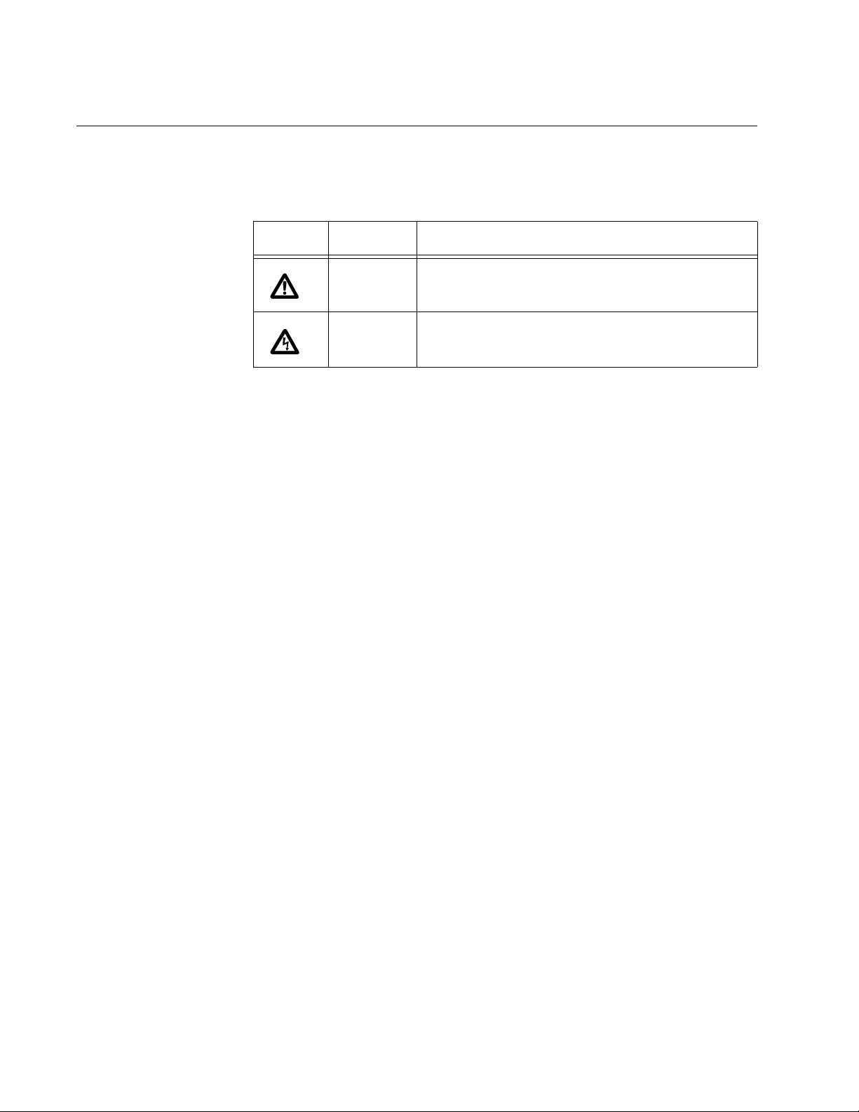
This document uses the safety symbols defined in Table 1.
Table 1. Safety Symbols
Symbol Meaning Description
Caution Performing or omitting a specific action may
result in equipment damage or loss of data.
Warning Performing or omitting a specific action may
result in electrical shock.
12
Page 13

Where to Find Web-based Guides
The installation and user guides for all Allied Telesis products are available
in portable document format (PDF) on our web site at
www.alliedtelesis.com. You can view the documents online or download
them onto a local workstation or server.
For details about the features and functions of the AT-10408XP switch,
refer to the AT-10408XP 10-Gigabit Ethernet Switch Installation Guide
(part number 613-000707) on our web site.
AT-S83 Management Software Command Line Interface User’s Guide
13
Page 14

Preface
Contacting Allied Telesis
This section provides Allied Telesis contact information for technical
support as well as sales or corporate information.
Online Support You can request technical support online by accessing the Allied Telesis
Knowledge Base from the following web site:
www.alliedtelesis.com/support/kb.aspx. You can use the Knowledge
Base to submit questions to our technical support staff and review
answers to previously asked questions.
Email and
Telephone
Support
For Technical Support via email or telephone, refer to the Allied Telesis
web site: www.alliedtelesis.com. Select your country from the list
displayed on the website. Then select the appropriate menu tab.
Warranty For warranty information, refer to the Allied Telesis web site:
www.alliedtelesis.com/warranty.
Returning
Products
For Sales or
Corporate
Products for return or repair must first be assigned a Return Materials
Authorization (RMA) number. A product sent to Allied Telesis without a
RMA number will be returned to the sender at the sender’s expense.
To obtain an RMA number, contact the Allied Telesis Technical Support
group at our web site: www.alliedtelesis.com/support/rma. Select your
country from the list displayed on the website. Then select the appropriate
menu tab.
You can contact Allied Telesis for sales or corporate information at our
web site: www.alliedtelesis.com. Select your country from the list
displayed on the website. Then select the appropriate menu tab.
Information
14
Page 15

Chapter 1
Getting Started with the Command Line Interface
This chapter describes the command modes of the AT-S83 command line
interface and how to access them. This chapter includes the following
sections:
“Introducing the Command Modes” on page 16
“Starting the Command Line Interface” on page 27
“Formatting Commands” on page 28
15
Page 16

Chapter 1: Getting Started with the Command Line Interface
Introducing the Command Modes
This chapter describes the CLI command modes and how to access the
command line interface. There are 8 command modes:
View
Privileged Executive
Configuration Terminal
Router
VLAN Configuration
Interface Configuration
Line
Key Chain
In the AT-S83 software, the commands are accessed through a hierarchy
of command modes. Each command mode contains a subset of
commands that are available within that mode only. For an illustration of
the command modes, see Figure 1 on page 17.
When you log on to the CLI interface, the default command mode that you
access depends on your login id. There are two default login ids that are
sent from the factory. The operator login id enables you to display the
software. With this login, you access the View command mode
automatically. The manager login id permits full administrator capabilities.
With this login, you access the Privileged Executive mode by default.
To navigate from one command mode to another, you enter a specific
command. For example, to access the Privileged Executive mode, you
enter the ENABLE command from the View mode. Once you enter a new
command mode, the AT-S83 prompt changes to indicate the new mode.
See Table 2 on page 18 for information about the commands used to
access the modes and their respective prompts.
16
Page 17

AT-S83 Management Software Command Line Interface User’s Guide
View mode
Router
mode
router rip
router ospf
VLAN
Configuration
mode
Privileged
Executive
Configuration
Terminal
VLAN
database
Interface
Configuration
mode
mode
interface
IFNAME
mode
enable
configure
terminal
line vty [FIRST]
(LAST)
Command used to
enter the next mode
Command used to
enter the next mode
Commands used to
enter the next mode
key chain
NAME
Line
mode
Key Chain
mode
Figure 1. AT-S83 Command Modes
1221
17
Page 18

Chapter 1: Getting Started with the Command Line Interface
Table 2. Command Modes
Command
Mode
Prompt Description
View mode Switch#
Privileged
Switch#
Executive
mode
Configuration
Switch(config)#
Terminal Mode
Router Mode Switch(config-router)#
This is the default command mode for the
operator login.
Enter the LOGOUT or EXIT commands
to quit the software.
This is the default command mode for the
manager login.
Access this mode from the View mode
with the ENABLE command.
Enter the DISABLE or EXIT commands
to return to the View mode.
Use the CONFIGURE command to enter
this mode from the Privileged Executive
mode.
To return to the Privileged Executive
mode, enter the END or EXIT
commands.
Type the ROUTER RIP or ROUTER
OSPF commands to enter this mode from
the Configuration Terminal mode.
18
Interface
Configuration
VLAN
Configuration
Switch(config-if)#
Switch(config-vlan)#
To return to the Configuration Terminal
mode, enter the END or EXIT
commands.
To access interface 1, enter the following
from the Configuration Terminal Mode:
interface xe1
Enter the END or EXIT commands to
return to the Configuration Terminal
mode.
From the Configuration Terminal mode,
type the VLAN DATABASE command.
Enter the END or EXIT commands to
return to the Configuration Terminal
mode.
Page 19

AT-S83 Management Software Command Line Interface User’s Guide
Table 2. Command Modes (Continued)
Command
Mode
Prompt Description
Line Switch(config-line)
Key Chain Switch(config-
keychain)#
In addition, there are commands that allow you to move between the
modes. For example, typing the EXIT command when you are in the
Interface Configuration mode returns you to the Configuration Terminal
mode. From the View mode, the LOGOUT command exits the software.
If you enter a command that is not accessible from a command mode, the
software displays a “command not found” message. For example, you can
enter the SHOW SNMP command from the Privileged Executive mode,
but you cannot enter this command from the VLAN Configuration mode.
Within the manual, a command mode is listed for each command.
From the Configuration Terminal mode,
type the LINE VTY command.
Enter the END or EXIT commands to
return to the Configuration Terminal
mode.
To enter this mode from the Configuration
Terminal mode, type the KEY CHAIN
command.
Enter the END or EXIT commands to
return to the Configuration Terminal
mode.
See the following sections for a description of each command mode:
“View Command Mode” on page 20
“Privileged Executive Command Mode” on page 21
“Configuration Terminal Mode” on page 22
“Interface Configuration Command Mode” on page 22
“Router Mode” on page 24
“VLAN Configuration Command Mode” on page 24
“Line Mode Commands” on page 25
“Key Chain Mode Command” on page 26
19
Page 20

Chapter 1: Getting Started with the Command Line Interface
View Command
Mode
The View command mode is the default command mode for the operator
login id. It permits access to basic commands. To indicate the View mode,
the prompt changes to “Switch>.” All of the commands in the View mode
are accessible from any of the other modes with the exception of the
ENABLE command.
See Table 3 on page 20 for a sample list of commands that can be
accessed from the View mode and a brief description of each command.
For more detailed information about the View mode commands, see
Chapter 4, “View Mode Commands” on page 45.
Table 3. View Mode Commands
Command Definition
CLEAR IP Clears the IP routing table and the stale kernel
route on the switch.
DEBUG DOT1X Turns on debugging is turned on for the 802.1x
protocol parameters.
ENABLE Changes the command mode from the View
mode to the Privilege Executive mode.
EXIT Exits the software from the View mode. From all
other modes, exits the current command mode
and returns to the previous mode.
LOGOUT Exits the software.
SHOW
RUNNINGCONFIG
Displays the current switch configuration.
20
Page 21

AT-S83 Management Software Command Line Interface User’s Guide
Privileged
Executive
Command Mode
The Privileged Executive command mode is the default command mode
for the manager login. The commands in this mode permit you to perform
system level commands such as rebooting the system, copying
configuration files, and clearing statistics. The prompt changes to
“Switch#” to indicate the Privileged Executive mode.
To access the View mode from the Privileged Executive mode, enter the
EXIT command. To return to the Privileged Executive mode, enter the
ENABLE command.
See Table 4 for a sample list of commands that can be access from the
Privileged Executive command mode. For detailed information about the
commands in this mode, see Chapter 5, “Privileged Executive Mode
Commands” on page 67.
Table 4. Privileged Executive Command Mode Commands
Command Description
BOOT CONFIGFILE
CONFIGURE
TERMINAL
Reboots the system.
Changes the mode to the Configuration
Terminal Mode.
COPY Uploads the configuration file to an image or
configuration file.
DISABLE Exits the Privileged Executive command mode.
PING IP Pings an IP address to check connectivity to
another system.
REBOOT Reboots the system.
SHOW
INTERFACE
Displays interface configuration and status.
21
Page 22

Chapter 1: Getting Started with the Command Line Interface
Configuration
Terminal Mode
The Configuration Terminal mode allows you to configure advanced
system features such as broadcast storm control, SNMP, and STP. To
access this mode, you must first access the Privileged Executive mode.
The prompt changes to “Switch(config)#” to indicate the software has
entered the Configuration Terminal mode.
See Table 5 for a sample list of commands that can be accessed from the
Configuration Terminal mode. For detailed information about the
commands in this mode, see the following chapters:
Chapter 6, “Configuration Terminal Mode Commands” on page 105
Chapter 7, “Internet Protocol (IP) Commands” on page 149
Chapter 8, “Simple Network Management Protocol (SNMP)
Commands” on page 155
Table 5. Configuration Terminal Command Mode Commands
Command Description
ACCESS-LIST Creates an access list.
ARP Sets an IP address for the Address Resolution
Protocol (ARP).
Interface
Configuration
Command Mode
LINE CONSOLE Sets the console configuration.
HOSTNAME Sets the name of the system.
INTERFACE Accesses the Interface Configuration command
mode (you must also specify an interface).
SNMP-SERVER
ENABLE
USERNAME Sets a system user name and password.
The Interface Configuration command mode allows you to configure
features that pertain to the interfaces such as flow control and duplex
mode. To access this mode, you must first access the Privileged
Executive and Configuration Terminal modes, depending on your login id.
For example, to access interface 1 enter the following from the
Configuration Terminal mode:
interface xe1
The prompt changes to “Switch(config-if)#” to indicate the Interface
Configuration mode.
Enables an SNMP agent on the switch.
22
After you have accessed this mode, the commands you enter apply only to
the interface specified in the Configuration Terminal mode. For example, if
you enter “interface xe3” in the Configuration Terminal mode, all of the
subsequent commands that you enter apply to interface 3 only. To
Page 23

AT-S83 Management Software Command Line Interface User’s Guide
perform interface-specific commands on another interface, specify the
new interface in the Interface Configuration mode.
For a sample list of commands that can be accessed from the Interface
Configuration command mode, see Table 6. For more detailed information
about the commands in the Interface Configuration mode, see the
following chapters:
Chapter 9, “Interface Configuration Mode Commands” on page 171.
Chapter 10, “IP Interface Commands” on page 209
Chapter 11, “802.1x Access Control Commands” on page 213
Chapter 12, “Port Configuration” on page 239
Chapter 13, “Spanning Tree Protocol (STP) Commands” on page 243
Table 6. Interface Configuration Command Mode Commands
Commands Description
ARP-AGEING-
Set a timer for ARP on a specific interface.
TIMEOUT
DOT1X MAXREQ
Sets the maximum number of reauthentication
attempts after authentication fails.
FLOWCONTROL ONEnables flow control and configures the flow
control mode for the interface.
IP ADDRESS Sets an IP address for the switch or specifies that
the switch uses a DHCP client to obtain an IP
address.
MAC-ADDRESS Sets the MAC address for a specified interface.
SHUTDOWN Disables an interface.
SPANNING-TREE
MODE
Sets the active spanning tree protocol and enables
it on the switch.
SPEED Sets the speed and duplex mode for an interface.
23
Page 24

Chapter 1: Getting Started with the Command Line Interface
Router Mode The Router mode permits access to Layer 3 routing commands using the
RIP and OSPF protocols. Access this mode through the Configuration
Terminal mode with the following commands:
ROUTER RIP
ROUTER OSPF
When you enter either of these commands, the prompt changes to
“Switch(config-router)#” to indicate the new mode.
For a sample list of RIP and OSPF commands, see Table 7. For more
information about the RIP and OSPF commands, see the following
chapters:
Chapter 14, “Routing Information Protocol (RIP) Commands” on page
269
Chapter 15, “Open Shortest Path First (OSPF) Commands” on page
311
Table 7. RIP and OSPF Commands
VLAN
Configuration
Command Mode
Commands Description
CLEAR IP RIP ROUTE Clears data from the RIP routing table.
DEFAULT-METRIC Specifies the metrics assigned to
redistributed routes.
HOST AREA Specifies a stub host entry belonging to an
area.
NEIGHBOR Specifies a neighbor router.
IP OSPF COST Specifies the cost of link-state metric in a
router-LSA.
IP OSPF
AUTHENTICATION-KEY
The VLAN Configuration command mode allows you to configure
commands that are applied to a VLAN interface. For instance, you can
assign an IP address to a VLAN interface in this mode.
To access this mode, you must first access the View, Privileged
Executive, and Configuration Terminal modes, depending on your login id.
From the Configuration Terminal command mode, type the VLAN
DATABASE command. The prompt changes to “Switch(config-vlan)#” to
indicate the VLAN Configuration mode.
Specifies an OSPF authentication
password for the neighboring routers.
24
After you have accessed the VLAN Configuration mode, you enter
commands that apply to specific VLANs. For a sample list of commands
Page 25

AT-S83 Management Software Command Line Interface User’s Guide
that can be accessed from the VLAN Configuration command mode, see
Table 8. For more detailed information about the commands in the VLAN
Configuration mode, see Chapter 17, “VLAN Commands” on page 359.
Table 8. VLAN Commands
Commands Description
SHOW VLAN Displays information about a particular
VLAN.
VLAN Creates a VLAN and enables it.
VLAN NAME Assigns a name to a VLAN.
VLAN STATE Sets the operational state of the VLAN.
Line Mode
Commands
To Line mode permits you to assign a console timeout, the length of the
console lines, and the user privilege level when creating a Telnet
connection. Access the Line mode through the Configuration Terminal
mode, with the LINE VTY command. The prompt changes to
“Switch(config-line)#” to indicate the Line mode.
For a list of commands that can be accessed from the Line mode, see
Table 9. For more information about this mode, see Chapter 16, “Line
Mode Commands” on page 355.
Table 9. Line Mode Commands
Command Description
EXEC-TIMEOUT Sets the interval the command interpreter
waits for user input detected.
LINE CONSOLE Sets the primary terminal line.
PRIVILEGE Sets the access level to the AT-S83
commands.
25
Page 26

Chapter 1: Getting Started with the Command Line Interface
Key Chain Mode
Command
The Key Chain mode is used to assign an authentication key. Use the
KEY CHAIN command to access this mode from the Configuration
Terminal mode. Within this mode, you can assign a key number.
For a list of commands that can be accessed from the Key Chain mode,
see Table 10. The commands in this mode are in Chapter 14, “Routing
Information Protocol (RIP) Commands” on page 269.
Table 10. Key Chain Mode Commands
Command Description
IP RIP AUTHENTICATION KEY-CHAIN Specifies the name of the
authentication key chain.
KEY Assigns a key number.
KEY CHAIN Accesses the Key Chain
mode.
26
Page 27

Starting the Command Line Interface
To start the command line interface, perform the following procedure:
1. Type the user id and password.
There are two default user ids and passwords. For the system
administrator login, the default user id is “manager” and the default
password is “friend.” For the operator login, the default user id is
“operator” and the default password is “operator.”
A command line prompt is displayed in Figure 2.
Username:manager
Password:
(none) #
AT-S83 Management Software Command Line Interface User’s Guide
Figure 2. Command Line Login Screen
The default switch name is “(none)” and the pound sign (#) prompt
indicates the Privileged Executive mode which is the default mode
accessed by the manager login.
If you login with the operator login id, the prompt changes to “none>” to
indicate the View mode.
27
Page 28

Chapter 1: Getting Started with the Command Line Interface
Formatting Commands
The AT-S83 software command line interface follows the same formatting
conventions for all of the command modes. There are command line
interface features which apply to the general use of the command line and
command syntax conventions which apply when entering the commands.
See the following sections.
Command Line
Interface
Features
The following features are supported in the command line interface:
Command history - Use the up and down arrow keys.
Context-specific help - Press the question mark key, ?, to display a list
of permitted parameters or all of the available commands for a
particular command mode. There are two formatting options:
– command ? - List the keywords or arguments that
are required by a particular command. A space
between a command and a question mark is required.
– abbreviated command? - Provides a list of
commands that begin with a particular character string.
There is no space between the command and the
question mark.
Keyword abbreviations - Any keyword can be recognized by typing an
unambiguous prefix, for example, type “sh” and the software responds
with “show.”
Tab key - Pressing the Tab key fills in the rest of the keyword
automatically. For example, typing “di” and then pressing the Tab key
enters “disable” on the command line.
Formatting
Conventions
Specifying an
28
Command
Interface
The following formatting conventions are used in this manual:
screen text font - This font illustrates the format of a command and
command examples.
ALL CAPITAL LETTERS- All capital letters indicate a parameter for
you to enter.
[ ] - Brackets indicate optional parameters.
| - Vertical line separates parameter options for you to choose from.
The AT-10408XP switch has eight 10G ports. Within the command line
interface, specify each interface with “xe” and the number of the interface.
For example, interface 3 is specified as “xe3.” For more information about
the ports, see “Port Descriptions” on page 36.
Page 29

AT-S83 Management Software Command Line Interface User’s Guide
Command Line
Syntax
Conventions
The following table describes the conventions used in the AT-S83
command interface.
Table 11. Command Line Syntax Conventions
Convention Description Example
A.B.C.D/M Indicates an IP address and a
subnet mask.
line Indicates a line of text that
accepts spaces without
quotation marks.
string Indicates a string of
alphanumeric characters,
including special characters
such as spaces. You must
place quotation marks around
a value with spaces.
int Indicates a whole integer. 202
IFNAME Indicates an interface name.
Specify values xe1 through
xe8 and eth0.
192.68.1.11/24
Switch 24, San
Jose, Building 4
“Switch 24, San
Jose, Building 4”
xe3
mask Indicates a subnet mask. 255.255.240.0
sec Indicates seconds. 120
min Indicates minutes. 8
trunk ID Indicates trunk group ID. 4
VLANID Indicates a VLAN instance
(including name and VLAN
identifier).
vlan3
29
Page 30

Chapter 1: Getting Started with the Command Line Interface
30
Page 31

Chapter 2
Introduction
This chapter covers the following topics:
“Ethernet Technology” on page 32
“Port Descriptions” on page 36
“Software Features” on page 37
31
Page 32

Chapter 2: Introduction
Ethernet Technology
This section describes the Ethernet technology used by the AT-S83
software.
Fast Ethernet The growing importance of LANs and the increasing complexity of desktop
computing applications are fueling the need for high performance
networks. A number of high-speed LAN technologies are proposed to
provide greater bandwidth and improve client and server response times.
Among them, Fast Ethernet, or 100T, provides a smooth evolution from
10T technology.
100Mbps Fast Ethernet is a standard specified by the IEEE 802.3 LAN
committee. It is an extension of the 10Mbps Ethernet standard with the
ability to transmit and receive data at 100Mbps, while maintaining the
Carrier Sense Multiple Access with Collision Detection (CSMA/CD)
Ethernet protocol.
Gigabit Ethernet
Technology
Gigabit Ethernet is an extension of IEEE 802.3 Ethernet that uses the
same packet structure, format, and support for CSMA/CD, protocol, full
duplex, flow control, and management objects, but with a tenfold increase
in theoretical throughput over 100Mbps Fast Ethernet and a one-hundred
fold increase over 10Mbps Ethernet. Since it is compatible with all 10Mbps
and 100Mbps Ethernet environments, Gigabit Ethernet provides a
straightforward upgrade without wasting a company’s existing investment
in hardware, software, and trained personnel.
The increased speed and extra bandwidth offered by Gigabit Ethernet are
essential to coping with the network bottlenecks that frequently develop as
computers and their busses get faster and more users use applications
that generate more traffic. Upgrading key components, such as your
backbone and servers to Gigabit Ethernet can greatly improve network
response time as well as significantly speed up the traffic between
subnetworks.
Gigabit Ethernet enabled fast optical fiber connections to support video
conferencing, complex imaging, and similar data-intensive applications. In
addition, since data transfers occur at 10 times faster than Fast Ethernet,
servers outfitted with Gigabit Ethernet NIC’s are able to perform 10 times
the number of operations in the same amount of time.
32
In addition, the phenomenal bandwidth delivered by Gigabit Ethernet is
the most cost effective method to take advantage of today and tomorrow’s
rapidly improving switching and routing internetworking technologies.
Page 33

AT-S83 Management Software Command Line Interface User’s Guide
Switching
Technology
Another key development pushing the limits of Ethernet technology is in
the field of switching technology. A switch bridges Ethernet packets at the
MAC address level of the Ethernet protocol transmitting among connected
Ethernet or Fast Ethernet LAN segments.
Switching is a cost-effective way of increasing the total network capacity
available to users on a LAN. A switch increases capacity and decreases
network loading by making it possible for a LAN to be divided into
segments, which are not competing with each other for network
transmission capacity. Therefore, the load on each segment is decreased.
The switch has a high-speed selective bridge between the individual
segments. Traffic that needs to go from one segment to another (from one
port to another) is automatically forwarded by the switch, without
interfering with other segments (ports). This ability allows the total network
capacity to be multiplied, while still maintaining the same network cabling
and adapter cards.
For Fast Ethernet or Gigabit Ethernet, a switch is an effective way of
eliminating the problem of chaining hubs beyond the two-repeater limit. A
switch can be used to split parts of the network into different collision
domains. For example, the switch can make it possible to expand a Fast
Ethernet network beyond the 205 meter network diameter limit for 100TX
networks. Switches supporting both traditional 10Mbps Ethernet and
100Mbps Fast Ethernet are also ideal for bridging between existing
10Mbps networks and new 100Mbps networks.
Routing Protocol
Support
Switching LAN technology is a marked improvement over the previous
generation of network bridges which were characterized by higher
latencies. Routers have also been used to segment local area networks,
but the cost of a router and the setup and maintenance required make
routers relatively impractical. The AT-10408XP switch is an ideal solution
to most kinds of LAN congestion problems.
The AT-S83 software supports IETF-compliant IPv4 and IPv6 versions of
OSPF (Open Shortest Path First) and RIP (Routing Information Protocol).
The RIP IPv4 Protocol Module supports both RIPv1 and RIPv2. In
addition, OSPFv2 and OSPFv3 protocol modules are provided with IPv4
and IPv6 support.
RIP
A distance-vector protocol, RIP is an Interior Gateway Protocol (IGP) that
uses hop counts as its metric. The AT-S83 software supports RIP module
supports RFCs 1058 and 1723. The RIPv2 module supports more fields in
the RIP packets as well as security authentication features.
At regular intervals of the routing update timer and at the time of change in
the topology, the RIP router sends update messages to other routers. The
listening routers update their route table with the new route, and increase
33
Page 34

Chapter 2: Introduction
the metric value of the path by one. (This is referred to as hop count.) The
router recognizes the IP-address-advertising router at the next hop, then it
sends the routing updates to other routers. A maximum allowable hop
count is 15. If a router reaches a metric of 16 or above, the destination is
defined as unreachable. This feature avoids indefinite routing loops. The
split horizon and hold down features are used to avoid propagating
incorrect routing information. The route becomes invalid when the route
time-out timer expires. It remains in the table until the route-flush timer
expires.
OSPF
A link-state routing protocol, OSPF, is an Interior Gateway Protocol (IGP)
that uses the SPF Dijsktra algorithm for the Internet. OSPF sends linkstate advertisements (LSAs) to all other routers within the same
hierarchical area. Data on attached interfaces, metrics used, and other
variables are included in OSPF LSAs. As OSPF routers accumulate linkstate data, they use the SPF algorithm to calculate the shortest path to
each node.
An Autonomous System (AS) or domain is defined as a group of networks
with a common routing infrastructure. OSPF can work in one AS. Or, it can
receive and send routes from (or to) different AS systems. An AS system
consist of areas which is a group of neighboring networks or attached
hosts.
All backbone OSPF area routers use the same procedures and algorithms
to maintain routing information within the backbone as any other area
router. The backbone topology is invisible to all routers within an area. The
individual area topologies are invisible to the backbone. Sometimes the
backbone is not a contiguous area. Virtual links function as if they were
direct links and are configured between backbone routers that share a link
to a non backbone area.
During boot-up, an OSPF router initializes its routing-protocol-specific data
structures and tables. When the lower-layer protocols with which it
interfaces are functional, it sends the OSPF Hello protocol packets to find
neighboring routers. A router sends Hello packets as keep-alive packets,
informing other routers about its continuing functionality.
Two routers are considered adjacent when their link state databases are
synchronized. Multi-access networks have more than two routers. On
multi-access networks, the hello protocol chooses a designated router and
a designated backup router. The designated router generates LSAs for the
entire multi-access network, and reduces network traffic and the size of
the topological database. The designated router also determines the
adjacency of routers and the synchronization of their topological
databases. The data on a router’s adjacencies or state changes are
provided by periodic transmission of an LSA. Failed routers are detected,
and topology is changed quickly by comparing adjacencies to link states.
34
Page 35

AT-S83 Management Software Command Line Interface User’s Guide
Each router calculates a shortest path tree, with itself as a root, from the
topological database generated from these LSAs. This shortest path tree
creates a routing table.
35
Page 36

Chapter 2: Introduction
Port Descriptions
The switch has 8 10-Gigabit ports, or interfaces, that may be used in
uplinking various network devices such as PCs, hubs, and other switches
to provide a gigabit Ethernet uplink in full-duplex mode. In addition, there
is a 10/100/1000Base-T port and a terminal port which is used to connect
to a console.
Within the software, the 8 10-Gigabit ports are accessed through the
Interface mode. Within the software, these ports are referred to as
interfaces. To access an interface, use the interface number prefaced by
“xe.” For example, to access interface 3 specify “xe3.” See Table 12 for a
list of the port names on the switch and how to refer to them in the
software.
The purpose of the 10/100/1000Base-T port is twofold. It is used to make
a Telnet connection to the switch. In addition, it is used to download or
upload files with TFTP. You can assign the 10/100/1000Base-T port an IP
address that is on a different subnet from interfaces 1 through 8. For
instance, you can assign an IP address on a different subnet for this port.
A subset of Interface mode commands are available on this port.
The terminal port is a console port and is it not available from the AT-S83
software.
For more information about the AT-10408XP switch, see AT-10408XP 10-
Gigabit Ethernet Switch Installation Guide.
Table 12. AT-10408XP Switch Ports
Port Name AT-S83 Software Name
1xe1
2xe2
3xe3
4xe4
5xe5
6xe6
7xe7
8xe8
10/100/1000Base-T eth0
36
Terminal Port not applicable
Page 37

Software Features
AT-S83 Management Software Command Line Interface User’s Guide
The AT-S83 software supports the following features:
IEEE 802.1x Port-based Network Access Control
IEEE 802.1d Spanning Tree, IEEE 802.1w Rapid Spanning Tree, and
IEEE 802.1s Multiple Spanning Tree support
IEEE 802.1q VLAN tagging and priority
Network Time Protocol (NTP) client support
TFTP and Xmodem download (RFC 783/1350 TFTP)
System Log Support
Ping
Telnet (client and server)
DHCP client support
System configuration/IP configuration
Back pressure
IEEE 802.3x 10/100Mbps Flow control
IEEE 802.3z 1000Mbps Flow control
Broadcast storm filtering support
Remote Authentication Dial-In User Service (RADIUS) client support
IEEE 802.1q Class of Service prioritization
IEEE 802.1q VLAN tagging and priority
IEEE 802.1x Port Based Network Access Control
IEEE 802.3 10BaseT Ethernet
IEEE 802.3ab 1000Base-T
IEEE 802.3u 100BaseTX Ethernet
RFC 1157 Simple Network Management Protocol (SNMP)
RFC 2571-5 SNMPv3
RFC 1058 Routing Information Protocol (RIP) Version 1
RFC 1723 Routing Information Protocol (RIP)
RFC 2082 Routing Information Protocol RIP-2 MD5 Authentication
RFC 2453 Routing Information Protocol (RIP) and Routing Information
Protocol Version 2 (RIPv2)
RFC 1765 Open Shortest Path First (OSPF) database overflow
RFC 2328 Open Shortest Path First version 2 (OSFPv2)
RFC 2370 OSPF Opaque LSA option
RFC 3101 The OSPF Not-So-Stubby Area (NSSA) Option
37
Page 38

Chapter 2: Introduction
RFC 3509 Alternative Implementation of OSPF Area Border Routers
Standard CLI
MIB support for:
– RFC 1155 SNMP MIB Tree
– RFC 1213 MIB-II
– RFC 1215 TRAP MIB
– RFC 1493 Bridge MIB
– RFC 1573 Interface Group MIB
– RFC 1643 Ethernet-like MIB
– RFC 1724 Routing Information Protocol (RIP)
MIB
– RFC 1850 Open Shortest Path First version 2
(OSFPv2) MIB
– RFC 2674 802.1Q MIB
Only the features listed above are supported.
38
Page 39

Chapter 3
Basic Management Features
This chapter provides the following sections:
“Creating User Accounts” on page 40
“SNMP Settings” on page 41
“Assigning an IP Address” on page 43
39
Page 40

Chapter 3: Basic Management Features
Creating User Accounts
There are two default login ids that are sent from the factory. The operator
login id enables you to display the software.The password for this user id
is “operator.” With this login, you access the View command mode
automatically. In contrast, the manager login id permits full administrator
capabilities. The password for this login id is “friend.” With this login, you
access the Privileged Executive mode by default.
After your initial login to the system, assign a new user id and password.
Keep the manager login id and the friend password in case you forget your
password.
One of the first tasks when settings up the switch is to create user
accounts. If you log in using the manager login id, you have privileged
access to the switch's management software. After your initial login, define
new login ids and passwords to prevent unauthorized access to the
switch. Be sure to record the passwords for future reference.
To create an administrator-level account for the switch, do the following:
1. From the Privileged Executive mode, type:
configuration terminal
The prompt changes to “switch(config)#” to indicate the Configuration
Terminal mode.
2. Use the USERNAME command to define a user name with
administrator privileges and a password. For example, the following
commands sets the user “nan” with administrative privileges and a
password of “topsecret12:”
username nan privilege 15 password topsecret12
3. Use the SHOW RUNNING-CONFIG command to verify the user name
and password. Type:
show running-config
Caution
CLI configuration commands only modify the running configuration
file and are not saved when the switch is rebooted. To save your
configuration changes in nonvolatile storage, use the COPY
command. See “COPY” on page 71.
40
Page 41

SNMP Settings
AT-S83 Management Software Command Line Interface User’s Guide
Simple Network Management Protocol (SNMP) is an OSI Layer 7
(Application Layer) designed specifically for managing and monitoring
network devices. SNMP enables network management stations to read
and modify the settings of gateways, routers, switches, and other network
devices. Use SNMP to configure system features for proper operation,
monitor performance and detect potential problems in the switch, switch
group, or network.
Managed devices that support SNMP include software (referred to as an
agent), which runs locally on the device.A defined set of variables
(managed objects) is maintained by the SNMP agent and used to manage
the device.These objects are defined in a Management Information Base
(MIB), which provides a standard presentation of the information controlled
by the on-board SNMP agent. SNMP defines both the format of the MIB
specifications and the protocol used to access this information over the
network.
The AT-10408XP supports SNMP versions 1, 2c, and 3.You can specify
which version of SNMP you want to use to monitor and control the
switch.The three versions of SNMP vary in the level of security provided
between the management station and the network device.
In SNMP v1 and v2, user authentication is accomplished using
“community strings,” which function like passwords.The remote user
SNMP application and the switch SNMP must use the same community
string. SNMP packets from any station that has not been authenticated are
ignored or dropped.
The default community strings for the switch used for SNMP v1 and v2
management access are:
public – Allows authorized management stations to retrieve MIB
objects.
private – Allows authorized management stations to retrieve and
modify MIB objects.
SNMP v3 uses a more sophisticated authentication process that is
separated into two parts.The first part is to maintain a list of users and their
attributes that are allowed to act as SNMP managers.The second part
describes what each user on that list can do as an SNMP manager.
The switch allows groups of users to be listed and configured with a
shared set of privileges.The SNMP version may also be set for a listed
group of SNMP managers.Thus, you may create a group of SNMP
managers that are allowed to view read-only information or receive traps
using SNMP v1 while assigning a higher level of security to another group,
such as granting read/write privileges using SNMP v3.
41
Page 42

Chapter 3: Basic Management Features
Traps Traps are messages that alert network personnel of events that occur on
MIBs Management and counter information are stored by the AT-10408XP
Using SNMP v3 individual users or groups of SNMP managers can be
allowed to perform or be restricted from performing specific SNMP
management functions.The functions allowed (or restricted) are defined
using the Object Identifier (OID) associated with a specific MIB. An
additional layer of security is available for SNMP v3 because SNMP
messages may be encrypted. For information about how to configure
SNMP v3 settings for the switch, see Chapter 8, “Simple Network
Management Protocol (SNMP) Commands” on page 155.
the switch.The events can be as serious as a reboot (someone
accidentally turned off the switch), or less serious like a port status
change.The switch generates traps and sends them to the trap recipient
(or network manager).Typical traps include trap messages for
Authentication Failure, Topology Change, and Broadcast/Multicast Storm.
switch in the Management Information Base (MIB).The switch uses the
standard MIB-II Management Information Base module. Consequently,
values for MIB objects can be retrieved from any SNMP-based network
management software. In addition to the standard MIB-II, the switch also
supports its own proprietary enterprise MIB as an extended Management
Information Base.The proprietary MIB may also be retrieved by specifying
the MIB Object Identifier. MIB values can be either read-only or read-write.
42
Page 43

Assigning an IP Address
Each switch must be assigned its own IP address, which is used for
communication with an SNMP network manager or another TCP/IP
application such as TFTP. (The switch does not have a default IP
address.) You can change the default IP address to meet your networking
address scheme. For the AT-10408XP switch, you assign IP addresses at
the Interface command mode. You can assign an IP address to the 10/
100/1000Base-T port as well as to each 10-Gigabit interface an IP
address. In addition, you can assign the 10/100/1000Base-T port an IP
address that is on a different subnet from interfaces 1 through 8. For more
information about the ports, see “Port Descriptions” on page 36.
There are two ways to assign an IP address to an interface: statically and
dynamically.
To assign a static IP address to an interface, use the following procedure:
1. Enter the Configuration Terminal mode, type:
AT-S83 Management Software Command Line Interface User’s Guide
configure terminal
2. Enter the interface mode, for example, 10/100/1000Base-T port:
interface eth0
3. Enter the IP address in the format xxx.xxx.xxx.xxx/yyy.yyy.yyy.yyy:
ip 158.53.12.1/255.0.0.0
Where the x's represent the IP address and the y's represent the
corresponding subnet mask.
To assign dynamically assign an IP address to an interface, use the
following procedure:
1. Enter the Configuration Terminal mode, type:
configure terminal
2. Enter the interface mode, for example, interface 1:
interface xe1
3. Specify DHCP:
ip dhcp
43
Page 44

Chapter 3: Basic Management Features
44
Page 45

Chapter 4
View Mode Commands
This chapter provides a description of the commands that are available
from the View mode. These commands permit basic configuration of the
switch. All of the following commands are also available in the Privileged
Executive mode.
This chapter contains the following commands:
“CLEAR ARP-CACHE” on page 46
“CLEAR IP” on page 47
“CLEAR MAC ADDRESS-TABLE” on page 48
“CLEAR SPANNING-TREE DETECTED PROTOCOLS” on page 49
“DEBUG DOT1X” on page 50
“DEBUG MSTP” on page 52
“DEBUG RIP” on page 53
“DEBUG RSTP” on page 54
“DEBUG SNMP” on page 55
“DEBUG STP” on page 56
“ENABLE” on page 57
“EXIT” on page 58
“HELP” on page 59
“LOGOUT” on page 60
“QUIT” on page 61
“SHOW INTERFACE SWITCHPORT” on page 62
“SHOW RUNNING-CONFIG” on page 64
45
Page 46

Chapter 4: View Mode Commands
CLEAR ARP-CACHE
Syntax
clear arp-cache
Parameters
none
Description
Use the CLEAR ARP-CACHE command to clear all of the dynamically
learned IP addresses of network devices and their corresponding MAC
addresses from the Address Resolution Protocol (ARP) cache.
Note
To delete the static ARP entries, use the NO ARP command.
Command Mode
View and Privileged Executive modes
Examples
The following command clears the ARP cache:
switch#clear arp-cache
Related Commands
“ARP” on page 109
46
Page 47

CLEAR IP
AT-S83 Management Software Command Line Interface User’s Guide
Syntax
clear ip mroute|ospf|pim|prefix-list|rip|route|
Parameters
ip Indicates Internet Protocol parameters. Choose from the
following:
mroute Deletes multicast route table entries.
ospf Clears the Open Shortest Path First (OSPF) data.
prefix-list Clears a prefix list.
rip Clears the Routing Information Protocol (RIP)
information.
route Clears the routing table.
Description
Use the CLEAR IP command to clear the IP routing table and the stale
kernel route on the switch.
Command Mode
View and Privileged Executive modes
Examples
The following command clears the IP routing table:
switch#clear ip rip
The following command clears the routing table:
switch#clear ip route
Related Commands
none
47
Page 48

Chapter 4: View Mode Commands
CLEAR MAC ADDRESS-TABLE
Syntax
clear mac address-table
Parameters
mac Indicates all of the Layer-2 MAC addresses. Choose from
the following:
dynamic Indicates all dynamic entries.
multicast Indicates all multicast entries.
static Indicates all MAC address entries configured
Description
through the management interface.
Use the CLEAR MAC command to clear the Layer-2 MAC addresses.
Command Mode
View and Privileged Executive modes
Example
The following command clears all of the dynamic Layer-2 MAC addresses:
switch#clear mac address-table dynamic
Related Commands
none
48
Page 49

AT-S83 Management Software Command Line Interface User’s Guide
CLEAR SPANNING-TREE DETECTED PROTOCOLS
Syntax
clear spanning-tree detected protocols interface
IFNAME
Parameters
IFNAME Indicates the name of the interface.
Description
Use this command to clear the Spanning Tree parameters from the
interface specified.
Command Mode
View and Privileged Executive modes
Example
The following command clears the Spanning Tree Protocol (that is STP,
RSTP, or MSTP) assigned to interface 1:
switcheroo spanning-tree detected protocols interface
xe1
Related Commands
none
49
Page 50

Chapter 4: View Mode Commands
DEBUG DOT1X
Syntax
debug dot1x all|event|nsm|packet|timer
no debug dot1x all|event|nsm|packet|timer
Parameters
dot1x Indicates the debugging is turned on for 802.1x protocol
parameters. Choose from the following:
all Turns on all 802.1x parameters for debugging.
event Turns on 802.1x events for debugging.
nsm Turns on 802.1x NSM information for debugging.
packet Turns on 802.1x packets for debugging.
timer Turns on 802.1x timer for debugging.
Description
Use the DEBUG DOT1X command to debug the 802.1x protocol
parameters. Use the no form of this command to turn off one component
of debugging.
Command Modes
View and Privileged Executive modes
Examples
The following command turns on debugging on all of the 802.1x
parameters:
switch#debug dot1x all
The following command turns on debugging of the 802.1x protocol timer:
50
switch#debug dot1x timer
The following command turns off debugging of 802.1x packets:
switch#no debug dot1x packet
Page 51

Related Commands
none
AT-S83 Management Software Command Line Interface User’s Guide
51
Page 52

Chapter 4: View Mode Commands
DEBUG MSTP
Syntax
debug mstp
Parameters
mstp Indicates the Multiple Spanning Tree Protocol.
all Turns on debugging for all of the following MSTP
parameters.
cli Turns on echo commands to console feature.
packet Turns on echo packet contents to console.
protocol Turns on echo protocol on console.
timer Turns on echo timer expiry to console.
Description
Use this command to debug MSTP parameters.
Command Modes
View and Privileged Executive modes
Examples
The following command debugs all of the MSTP parameters:
switch#debug mstp all
The following command displays (or echoes) MSTP commands on the
console:
switch#debug mstp cli
Related Commands
52
none
Page 53

DEBUG RIP
AT-S83 Management Software Command Line Interface User’s Guide
Syntax
debug rip all|events|nsm|packet
no debug all|events|nsm|packet
Parameters
rip Indicates the Routing Information Protocol.
all Turns on debugging for all of the RIP parameters
listed below.
events Turns on debugging for RIP events.
nsm Turns on debugging for NSM information.
packet Turns on debugging of RIP packets.
Description
Use this command to debug RIP parameters. Use the no form of this
command to turn off debugging for the specified set of RIP parameters.
Command Modes
View and Privileged Executive modes
Examples
The following command debugs RIP events:
switch#debug rip events
The following command debugs RIP packets:
switch#debug rip packets
The following command turns off debugging of all RIP parameters:
switch#no debug rip all
Related Commands
none
53
Page 54

Chapter 4: View Mode Commands
DEBUG RSTP
Syntax
debug rstp
Parameters
rstp Indicates the Rapid Spanning Tree Protocol (RSTP).
all Turns on debugging for all of the following RSTP
parameters.
cli Turns on echo commands to console feature.
event Turns on echo events to console feature.
packet Turns on echo packet contents to console.
sync Turns on echo synchronization to console.
timer Turns on echo timer expiry to console.
Description
Use this command to debug RSTP parameters.
Command Modes
View and Privileged Executive modes
Examples
The following command debugs all of the RSTP parameters:
switch#debug rstp all
The following command displays (or echoes) RSTP commands to the
console:
switch#debug rstp cli
54
Related Commands
none
Page 55

DEBUG SNMP
AT-S83 Management Software Command Line Interface User’s Guide
Syntax
debug snmp
Parameters
none
Use this command to debug SNMP parameters.
Command Modes
View and Privileged Executive modes
Examples
The following command turns on debugging for SNMP:
switch#debug snmp
Related Commands
none
55
Page 56

Chapter 4: View Mode Commands
DEBUG STP
Syntax
debug stp all|cli|event|packet|sync|timer
Parameters
stp Indicates the Spanning Tree Protocol.
all Turns on debugging for all of the following STP
parameters.
cli Turns on echo commands to the console.
event Turns on echo events to console.
packet Turns on echo packet contents to the console.
protocol Turns on protocol change to the console.
timer Turns on echo timer expiry to the console.
Description
Use this command to access STP parameters.
Command Modes
View and Privileged Executive modes
Examples
The following command debugs all of the STP parameters:
switch#debug stp all
The following command displays (or echoes) STP commands on the
console:
switch#debug stp cli
56
Related Commands
none
Page 57

ENABLE
AT-S83 Management Software Command Line Interface User’s Guide
Syntax
enable
Parameters
none
Description
Use this command to access the Privileged Executive mode from the View
mode. After you enter this command, the prompt changes to indicate you
have access to the Privileged Executive mode.
Command Mode
View mode
Example
The following is an example of the ENABLE command and the Privileged
Executive prompt:
switch>enable
switch#
Related Commands
none
57
Page 58

Chapter 4: View Mode Commands
EXIT
Syntax
exit
Parameters
none
Description
Use this command to exit the current mode and return to the previous
mode. For example, if you enter this command in the Privileged Executive
mode, you are returned to the View mode.
Command Mode
All modes
Example
The following is an example of the exit command:
switch#exit
Related Commands
none
58
Page 59

HELP
AT-S83 Management Software Command Line Interface User’s Guide
Syntax
help
Parameters
none
Description
Use this command to display information about the CLI. The HELP
command provides information about the current parameter. There are
two forms of the HELP command:
Full help is available when you enter a command followed by a space
and the question mark (?). This displays all of the parameters for the
command.
Partial help is available when you enter an abbreviated command or
argument immediately followed by the question mark (?) without a
space. For example, “show con?” In this case, the software responds
by displaying, “SHOW CONFIGURE.”
Command Mode
All modes
Examples
The following is an example of full help and the display:
switch#clear ?
ip Internet Protocol (IP)
mac Clear layer 2 MAC entries
spanning-tree spanning-tree
The following is an example of partial help and the display:
switch#snmp-server u?
switch#snmp-server user
Related Commands
none
59
Page 60

Chapter 4: View Mode Commands
LOGOUT
Syntax
logout
Parameters
none
Description
Use the LOGOUT command to quit the View or Privileged Executive
modes and log out of the software.
Command Mode
View and Privileged Executive modes
Example
The following is an example of the LOGOUT command:
switch#logout
Related Commands
“QUIT” on page 61
60
Page 61

QUIT
AT-S83 Management Software Command Line Interface User’s Guide
Syntax
quit
Parameters
none
Description
Use the QUIT command to quit the current mode and return to the
previous mode. If you enter this command from the View or Privileged
modes, you are logged out of the software.
Command Mode
All modes
Example
The following is an example of the QUIT command:
switch#quit
Related Commands
“LOGOUT” on page 60
61
Page 62

Chapter 4: View Mode Commands
SHOW INTERFACE SWITCHPORT
Syntax
show interface switchport all
Parameters
none
Description
Use the SHOW INTERFACE SWITCHPORT command to display the
status of the 8 10-Gigabit ports.
Command Mode
View mode
Example
The following is an example of the SHOW INTERFACE SWITCHPORT
command and the sample output:
switch#show interface switchport
Interface name: xe1
Switchport mode: access
Ingress filter: enable
Acceptable frame types: all
Default Vlan: 1
Configured Vlans: 2
Interface name: xe2
Switchport mode: access
Ingress filter: enable
Acceptable frame types: all
Default Vlan: 1
Configured Vlans: 2
Interface name: xe3
Switchport mode: access
Ingress filter: enable
Acceptable frame types: all
Default Vlan: 1
Configured Vlans: 3
Interface name: xe4
Switchport mode: access
Ingress filter: enable
Acceptable frame types: all
Default Vlan: 1
Configured Vlans: 3
62
Page 63

AT-S83 Management Software Command Line Interface User’s Guide
Interface name: xe5
Switchport mode: access
Ingress filter: enable
Acceptable frame types: all
Default Vlan: 1
Configured Vlans: 3
Interface name: xe6
Switchport mode: access
Ingress filter: enable
Acceptable frame types: all
Default Vlan: 1
Configured Vlans: 3
Interface name: xe7
Switchport mode: access
Ingress filter: enable
Acceptable frame types: all
Default Vlan: 1
Configured Vlans: 3
Interface name: xe8
Switchport mode: access
Ingress filter: enable
Acceptable frame types: all
Default Vlan: 1
Configured Vlans: 3
Related Commands
none
63
Page 64

Chapter 4: View Mode Commands
SHOW RUNNING-CONFIG
Syntax
show running-config
Parameters
none
Description
Use this command to display information about the system.
Command Mode
All modes
Example
The following is an example of the SHOW RUNNING-CONFIG command
and a sample of the output:
switch#show running-config
!
no service password-encryption
!
no service dhcp
username manager privilege 15 password friend
username operator password operator
hostname switch
!!
log trap warnings
ip domain-lookup
!
spanning-tree mode ieee
spanning-tree acquire
!
!
interface eth0
no switchport
shutdown
64
Page 65

AT-S83 Management Software Command Line Interface User’s Guide
interface 1o
mtu 0
ip address 127.0.0.1/8
shutdown
interface vlan1
interface xe1
no switchport
ip address 10.10.12.10/24
!
interface xe2
switchport mode access
!
interface xe3
switchport mode access
!
interface xe4
switchport mode access
!
interface xe5
no switchport
ip address 10.10.10.22/24
!
interface xe6
switchport mode access
!
interface xe7
no switchport
ip address 10.10.13.22/24
!
interface xe8
switchport mode access
!
maximum-paths 8
!
snmp-server enable trap environ fan
snmp-server enable trap environ temp
snmp-server enable trap environ volt
!
login
line vty 0 4
login
!
end
Related Commands
“WRITE” on page 102
65
Page 66

Chapter 4: View Mode Commands
66
Page 67

Chapter 5
Privileged Executive Mode Commands
This chapter provides a description of the commands that are available
from the Privileged Executive mode. These commands permit basic
configuration of the switch and access to the 802.1x protocol. In addition,
you can display the current configuration of the switch. From this protocol,
all of the View mode commands (with the exception of the ENABLE
command) are available.
This chapter contains the following commands:
“BOOT CONFIG-FILE” on page 69
“CONFIGURE TERMINAL” on page 70
“COPY” on page 71
“DISABLE” on page 72
“DOWNLOAD A.B.C.D FILE-NAME” on page 73
“DOWNLOAD SERIAL” on page 74
“DOT1X INITIALIZE” on page 75
“PING IP” on page 76
“SHOW BOOT” on page 77
“SHOW FLOWCONTROL INTERFACE” on page 78
“SHOW INTERFACE” on page 79
“SHOW INTERFACE STATUS ALL” on page 80
“SHOW NTP ASSOCIATIONS DETAIL” on page 81
“SHOW NTP STATUS” on page 82
“SHOW STATIC-CHANNEL-GROUP” on page 83
“SHOW SYSTEM STATUS” on page 84
“SHOW VERSION” on page 85
“SYSTEM REBOOT” on page 86
“TELNET” on page 87
“TERMINAL” on page 88
“UNDEBUG ALL” on page 89
“UNDEBUG DOT1X” on page 90
“UNDEBUG OSPF EVENTS” on page 91
“UNDEBUG OSPF IFSM” on page 92
67
Page 68

Chapter 5: Privileged Executive Mode Commands
“UNDEBUG OSPF LSA” on page 93
“UNDEBUG OSPF NFSM” on page 94
“UNDEBUG OSPF NSM” on page 95
“UNDEBUG OSPF PACKET” on page 96
“UNDEBUG OSPF ROUTE” on page 98
“UNDEBUG RIP” on page 99
“UPLOAD A.B.C.D FILE-NAME” on page 100
“UPLOAD SERIAL” on page 101
“WRITE” on page 102
68
Page 69

BOOT CONFIG-FILE
Syntax
boot config-file WORD
Parameters
WORD-file Indicates the name of the boot configuration file. You
Description
Use the BOOT CONFIG-FILE command to reboot the system.
Command Mode
Privileged Executive mode
AT-S83 Management Software Command Line Interface User’s Guide
must use the “-file” naming convention.
Example
The following command reboots the system with a file called “default-file:”
switch#boot config-file default-file
Related Commands
none
69
Page 70

Chapter 5: Privileged Executive Mode Commands
CONFIGURE TERMINAL
Syntax
configure terminal
Parameters
none
Description
Use this command to access the Configuration Terminal mode from the
from the Privileged Executive mode. Once you access this mode, the
prompt changes.
Command Mode
Privileged Executive mode
Example
The following is an example of the CONFIGURE TERMINAL command
and the display of the software:
switch#configure terminal
switch(conf)#
Related Commands
none
70
Page 71

COPY
AT-S83 Management Software Command Line Interface User’s Guide
Syntax
copy running-config startup-config
Parameters
running-config Indicates the running configuration file.
startup-config Indicates the start-up configuration file.
Description
Use this command to copy files. List the running configuration first then list
the start-up configuration file.
Command Mode
Privileged Executive mode
Example
In the following example, the running configuration file is copied to the
startup configuration file which is named “startup-config:”
switch#copy running-config startup-config
The software displays the following:
Building configuration...
[OK]
Related Commands
none
71
Page 72

Chapter 5: Privileged Executive Mode Commands
DISABLE
Syntax
disable
Parameters
none
Description
Use the DISABLE command to exit the Privileged Executive mode and
return to the View mode.
To return to the Privileged Executive mode from the View mode, use the
ENABLE command.
Command Mode
Privileged Executive mode
Example
The following is an example of the DISABLE command:
switch#disable
Related Commands
“ENABLE” on page 57
72
Page 73

DOWNLOAD A.B.C.D FILE-NAME
Syntax
download A.B.C.D FILENAME
Parameters
A.B.C.D Indicates the IP address of an TFTP server. Specify
the IP address in the following format:
xxx.xxx.xxx.xxx
FILENAME Specifies a filename of a software image file.
Description
Use this command to download a software image from a TFTP server onto
the switch.
AT-S83 Management Software Command Line Interface User’s Guide
Command Mode
Privileged Executive mode
Examples
The following command uses a TFTP server, with an IP address of
189.11.1.1, to download the file called “ATS83_v100.img” onto the switch:
switch#download 189.11.1.1 ATS83_v100.img
Related Commands
none
73
Page 74

Chapter 5: Privileged Executive Mode Commands
DOWNLOAD SERIAL
Syntax
download serial xmodem
Parameters
serial Indicates the serial port. Choose from the following option:
Description
Use this command to download a software image from a serial port onto
the switch.
xmodem Indicates the xmodem protocol is used to
download a software image.
Command Mode
Privileged Executive mode
Examples
The following command uses the xmodem protocol to download the
software onto the switch:
switch#download serial xmodem
Related Commands
none
74
Page 75

DOT1X INITIALIZE
Syntax
dot1x initialize interface IFNAME
Parameters
IFNAME Specifies the name of an interface.
Description
Use this command to initialize the 802.1X Port-Based Access Control
feature on a specific interface.
Command Mode
Privileged Executive mode
AT-S83 Management Software Command Line Interface User’s Guide
Example
The following command initializes the 802.1X Port-Based Access Control
feature on interface 2:
switch#dot1x initialize interface xe2
Related Commands
none
75
Page 76

Chapter 5: Privileged Executive Mode Commands
PING IP
Syntax
ping ip WORD
Parameters
WORD Specifies the hostname or an IP address in the
Description
This command instructs the switch to ping an end node. You can use this
command to determine whether an active link exists between the switch
and another network device.
following format:
xxx.xxx.xxx.xxx
Command Mode
Privileged Executive mode
Example
The following command pings an end node with the IP address of
142.245.22.22:
switch#ping ip 142.245.22.22
The results of the ping are displayed on the screen.
Related Commands
none
76
Page 77

SHOW BOOT
AT-S83 Management Software Command Line Interface User’s Guide
Syntax
show boot
Parameters
none
Description
Use the SHOW BOOT to display information about the boot environment
variables.
Command Mode
All modes
Example
The following is an example of the SHOW BOOT command and a sample
display:
switch#show boot
Config file: /cfg/default.cfg
Related Commands
none
77
Page 78

Chapter 5: Privileged Executive Mode Commands
SHOW FLOWCONTROL INTERFACE
Syntax
show flowcontrol interface INTERFACE
Parameters
INTERFACE Specifies the name of an interface.
Description
Use the SHOW FLOWCONTROL INTERFACE command to display flow
control information.
To modify the lines displayed on the screen, use the | (output modifier
token). To save the output to a file, use the > (output reduction token).
Command Mode
Privileged Executive mode
Example
The following command displays flow control information on interface 4:
switch#show flowcontrol interface xe4
The following is a sample output of the SHOW FLOWCONTROL
INTERFACE command.
Table 13. SHOW FLOWCONTROL INTERFACE Command
Port Send FlowControl Receive FlowControl RxPause TxPause
admin oper admin oper
------------- ------------- ------------- ------------- ------------- ------------- -------------
xe1onononon00
Related Commands
78
none
Page 79

SHOW INTERFACE
Syntax
show interface (IFNAME)
Parameters
IFNAME Specifies the name of an interface. This is an optional
Description
Use the SHOW INTERFACE command to display the configuration and
status of an interface. If you do not specify an interface, this command
displays the status of all the interfaces.
Command Mode
AT-S83 Management Software Command Line Interface User’s Guide
parameter.
Privileged Executive mode
Example
The following is an example of the SHOW INTERFACE command on
interface 1 and the sample output:
switch#show interface xe1
Interface xe1
Scope: both
Hardware is Ethernet, address is 0004.2104.0801 (bia
004.2104.0801)
index 2001 metric 1 mtu 1500 duplex-full arp ageing
timeout 0
speed unknown mdix mdi
<UP,BROADCAST,MULTICAST>
VRF Binding: Not bound
VRF Binding: not bound
input packets 00, bytes 00, dropped 00, multicast
packets 00
output packets 00, bytes 00, multicast packets 00
broadcast packets 00
Related Commands
none
79
Page 80

Chapter 5: Privileged Executive Mode Commands
SHOW INTERFACE STATUS ALL
Syntax
show interface status all
Parameters
none
Description
Use the SHOW INTERFACE STATUS ALL command to display the
status, speed, duplex mode, and type of all the interfaces on a switch.
Command Mode
Privileged Executive mode
Example
The following example displays the command and its resulting output:
switch#show interface status all
Port Name Status Speed Duplex Type
eth0 1000Base-T connected 1000 full unknown
xe1 interface1 connected 10G full XFP
xe2 interface2 connected 10G full XFP
xe3 interface3 connected 10G full XFP
xe4 interface4 connected 10G full XFP
xe5 interface5 connected 10G full XFP
xe6 interface6 connected 10G full XFP
xe7 interface7 connected 10G full XFP
xe8 interface8 connected 10G full XFP
Related Commands
“SPEED” on page 196
80
Page 81

AT-S83 Management Software Command Line Interface User’s Guide
SHOW NTP ASSOCIATIONS DETAIL
Syntax
show ntp associations detail
Parameters
none
Description
Use the SHOW NTP ASSOCIATIONS DETAIL command to display
detailed information about the Network Time Protocol (NTP).
Command Mode
All modes
Example
The following is an example of the SHOW NTP ASSOCIATIONS DETAIL
command:
switch#show ntp associations detail
192.168.1.100 configured, sane, valid, leap_sub, stratum 16
ref ID INIT, time 00000000.00000000 ( 6:28:16.000 UTC
Fri Feb 7 2007
our mode client, peer mode unspec, our poll intvl 6,
peer poll intvl 10
root delay 0.00 msec, root disp 0.00, reach 000
delay 0.00 msec, offset 0.0000 msec, dispersion 0.00
precision 2**-20,
org time 00000000.00000000 ( 6:28:16:000 UTC Fri Feb 7 2007)
rec time 00000000.00000000 ( 6:28:16:000 UTC Fri Feb 7
2007)
xmt time 83aa7f8f.635ba2be (0:4:31:388 UTC Fri Jan 1 2007)
filtdelay = 0.00 0.00 0.00 0.00 0.00 0.00 0.00 0.00
filtoffset = 0.00 0.00 0.00 0.00 0.00 0.00 0.00 0.00
filterror = 16000.00 16000.00 16000.00 16000.00 16000.00
16000.00 16000.00 16000.00
Related Commands
“SHOW NTP STATUS” on page 82
81
Page 82

Chapter 5: Privileged Executive Mode Commands
SHOW NTP STATUS
Syntax
show ntp status
Parameters
none
Description
Use the SHOW NTP STATUS command to display information
about NTP.
Command Mode
All modes
Example
The following example shows the SHOW NTP STATUS command and a
sample of the output:
switch#show ntp status
Clock is unsynchronized, stratum 16, reference is INIT
actual frequency is 0.0000 Hz, precision is 2**-19
reference time is 00000000.00000000 ( 6:28:16.000 UTC Fri
Feb 7 2007)
clock offset is 0.000msec, root delay is 0.000 msec
root dispersion is 3540.000 msec.
Related Commands
“SHOW NTP ASSOCIATIONS DETAIL” on page 81
82
Page 83

SHOW STATIC-CHANNEL-GROUP
Syntax
show static-channel-group
Parameters
none
Description
Use the SHOW STATIC-CHANNEL-GROUP command to all configured
static aggregators and their corresponding member ports.
Command Mode
Privileged Executive mode
AT-S83 Management Software Command Line Interface User’s Guide
Example
The following example shows the SHOW STATIC-CHANNEL-GROUP
command and a sample of the output:
switch#show static-channel-group
% Static Aggregator: sa1
% Member:
xe1
xe2
xe3
% Static Aggregator: sa2
% Member:
xe4
Related Commands
none
83
Page 84

Chapter 5: Privileged Executive Mode Commands
SHOW SYSTEM STATUS
Syntax
show system status
Parameters
none
Description
Use the SHOW SYSTEM STATUS command to display information about
the system power and fan status.
Command Mode
All modes
Example
The following is an example of the SHOW SYSTEM STATUS command:
switch#show system status
System hardware status:
System 1.25V Power............ 1.238V
System 1.8V Power ............ 1.810V
System 3.0V Power ............ 2.995V
System 3.3V Power ............ 3.300V
System 5V Power .............. 5.26V
System 12V Power ............. 11.875V
System Temperature (Celsius).. 31 C
System Fan 1 Speed ........... 4963 RPM
System Fan 2 Speed ........... 4963 RPM
System Fan 3 Speed ........... 4963 RPM
System Fan 4 Speed ........... 4921 RPM
System Fan 5 Speed ........... 4821 RPM
Main PSU Power.................On
Main PSU Temp................. Normal
Main PSU Fan.................. Functional
Main PSU ..................... Installed
RPS PSU Power................. Off
RPS PSU Temp.................. Normal
RPS PSU Fan................... Functional
RPS PSU ...................... Installed
84
Related Commands
none
Page 85

SHOW VERSION
AT-S83 Management Software Command Line Interface User’s Guide
Syntax
show version
Parameters
none
Description
Use the SHOW VERSION command to display the information about the
software, including:
Version and cycle of the software
Build date and time
Host name
Ethernet address
Command Mode
All modes
Example
The following example displays the command and its resulting output:
switch#show version
Product ID=ATS83
Application Version=1.0.0
Application Cycle=Cycle_E
Application BuildTime=19:33:00
Application BuildDate=Mar 22 2007
Loader Version=1.0.0
Loader Cycle=Cycle_A
Serial Number=None
Model=AT-10408XP
HwRev=A
Ethaddr=00:03:84:fe:d2:00
Baudrate=115200
Uptime=13:21:12 up 0 min, load average: 1.41, 0.38, 0.12
Related Commands
none
85
Page 86

Chapter 5: Privileged Executive Mode Commands
SYSTEM REBOOT
Syntax
system reboot
Parameters
none
Description
Use the SYSTEM REBOOT to reboot the system.
Command Mode
All modes
Example
The following is an example of the SYSTEM REBOOT command and a
sample of the display:
switch#system reboot
The system is going down NOW!!!
Sending SIGTERM to all processes.
NSM[63]: NSM: Terminating on signal
STP[65]: STP: Terminating on signal
RSTP[67]: RSTP: Terminating on signal
MSTP[69]: MSTP: Terminating on signal
RIP[71]: RIP: Terminating on signal
OSPF[77]: OSPF: Terminating on signal
Sending SIGKILL to all processes.
Please stand by while rebooting the system.
Restarting system.
Related Commands
none
86
Page 87

TELNET
AT-S83 Management Software Command Line Interface User’s Guide
Syntax
telnet ipaddress
Parameters
ipaddress Specifies the IP address of a remote system in the
following format:
xxx.xxx.xxx.xxx
Description
Use this command to open a Telnet connection with a remote host. The
default setting for Telnet connections is disabled.
Command Mode
Privileged Executive mode
Example
The following is an example of the TELNET command to a remote host
with an IP address of 149.245.22.22:
switch#telnet 149.245.22.22
Related Commands
none
87
Page 88

Chapter 5: Privileged Executive Mode Commands
TERMINAL
Syntax
terminal length
no terminal length
Parameters
length Specifies the number of lines that are displayed on
Description
Use this command to set the number of lines on a screen or display output
from a debug command.
the console. Choose a value between 0 and 512
lines.
Command Mode
Privileged Executive mode
Examples
The following command sets the number of lines on a screen to 250:
switch#terminal length 250
Related Commands
none
88
Page 89

UNDEBUG ALL
AT-S83 Management Software Command Line Interface User’s Guide
Syntax
undebug all
Parameters
none
Description
Use the UNDEBUG ALL command to disable all of the debugging
commands on the switch.
Command Mode
Privileged Executive mode
Example
The following command disables all of the debugging commands on the
switch:
switch#undebug all
Related Commands
none
89
Page 90

Chapter 5: Privileged Executive Mode Commands
UNDEBUG DOT1X
Syntax
undebug dot1x all|event|nsm|packet|timer
Parameters
dot1x Indicates the IEEE 802.1x Protocol-based Access Control.
Choose from the following:
all Turns off all 802.1x parameters for debugging.
event Indicates 802.1x events.
nsm Indicates 802.1x NSM information.
packet Indicates 802.1x packets.
timer Indicates 802.1x timer.
Description
Use this command to disable 802.1x protocol debugging.
Command Modes
View and Privileged Executive modes
Examples
The following UNDEBUG 802.1x command disables debugging on all of
the 802.1x parameters:
switch#undebug dot1x all
The following is an example of the UNDEBUG 802.1x command disables
debugging on the 802.1x protocol timer:
switch#undebug dot1x timer
Related Commands
90
none
Page 91

UNDEBUG OSPF EVENTS
Syntax
undebug ospf events abr|asbr|lsa|nssa|os|router|vlink
no undebug ospf events
Parameters
abr Displays ABR events.
asbr Displays ASBR events.
lsa Displays Link State Advertisements (LSA) events.
nssa Displays NSSA events.
os Displays OS interaction events.
AT-S83 Management Software Command Line Interface User’s Guide
router Displays other router events.
vlink Displays virtual link events.
Description
Use the UNDEBUG OSPF EVENT command to disable the display of
debug information related to OSPF internal events. Use this command
without any parameters to turn on all of the options.
Use the no form of this command to disable this function.
Command Modes
Privileged Executive and Configuration Terminal modes
Examples
The following command turns on all of the OSFP debugging commands:
switch(config)#undebug ospf event
The following command displays OS interaction events on the console:
switch(config)#undebug ospf event os
Related Commands
“LOG FILE” on page 129
91
Page 92

Chapter 5: Privileged Executive Mode Commands
UNDEBUG OSPF IFSM
Syntax
undebug ospf ifsm status|events|timers
no undebug ifsm status|events|timers
Parameters
status Displays Interface Finite State Machine (IFSM) status
events Displays IFSM event information.
timers Displays IFSM timer information.
Description
information.
Use the UNDEBUG OPSF IFSM command to disable debugging options
for OSPF IFSM. Use the no form of this command to disable this function.
Command Modes
Privileged Executive and Configuration Terminal modes
Examples
The following command disables debugging of IFSM status information:
switch(config)#undebug ospf ifsm status
The following command disables debugging of IFSM timer information:
switch(config)#undebug ospf ifsm timers
Related Commands
“LOG FILE” on page 129
92
Page 93

UNDEBUG OSPF LSA
Syntax
undebug ospf lsa flooding|generate|install|maxage
|refresh
no undebug lsa status|events|timers
Parameters
flooding Displays Link State Advertisements (LSA) flooding information.
generate Displays LSA generation information.
install Displays LSA installation information.
maxage Displays the maximum age of the LSA in seconds.
AT-S83 Management Software Command Line Interface User’s Guide
refresh Displays the LSA refresh information.
Description
Use the UNDEBUG OSPF LSA command to disable the display of
troubleshooting information related to the internal operations of LSAs. Use
the no form of this command to disable this function.
Command Modes
Privileged Executive and Configuration Terminal modes
Examples
The following command disables the display of LSA refresh information:
switch(config)#undebug ospf lsa refresh
The following command disables the display of the maximum age of
the LSA:
switch(config)#undebug ospf lsa maxage
Related Commands
“LOG FILE” on page 129
93
Page 94

Chapter 5: Privileged Executive Mode Commands
UNDEBUG OSPF NFSM
Syntax
undebug ospf nfsm status|events|timers
no undebug nfsm status|events|timers
Parameters
status Displays Neighbor Finite State Machine (NFSM) status
events Displays NFSM event information.
timers Displays NFSM timer information.
Description
information.
Use the UNDEBUG OSPF NFSM command to disable the display of
debugging information related to NFSM.
Use the no form of this command to disable this function.
Command Modes
Privileged Executive and Configuration Terminal modes
Examples
The following command disables the display of NFSM status information:
switch(config)#undebug ospf nfsm status
The following command disables the display of NFSM event information:
switch(config)#undebug ospf nfsm events
Related Commands
“LOG FILE” on page 129
94
Page 95

UNDEBUG OSPF NSM
Syntax
undebug ospf nsm interface|redistribute
no undebug nsm interface|redistribute
Parameters
interface Specifies NSM interface information.
redistribute Specifies NSM redistribute information.
Description
Use the UNDEBUG OSPF NSM command to disable debugging options
for OSFP NSM. Use the no form of this command to disable this function.
AT-S83 Management Software Command Line Interface User’s Guide
Command Modes
Privileged Executive and Configuration Terminal modes
Examples
The following command disables the display of NSM interface information:
switch(config)#undebug ospf nsm interface
The following command disables the display of NSM redistribute
information:
switch(config)#undebug ospf nsm redistribute
Related Commands
“LOG FILE” on page 129
95
Page 96

Chapter 5: Privileged Executive Mode Commands
UNDEBUG OSPF PACKET
Syntax
undebug ospf packet dd|detail|hello|ls-ack
|ls-request|ls-update|recv|send
no undebug ospf packet dd|detail|hello|ls-ack
|ls-request|ls-update|recv|send
Parameters
dd Specifies debugging for OSPF database information.
detail Sets the debug option to detailed information.
hello Specifies debugging for OSPF hello packets.
ls-ack Specifies debugging for OSPF link-state
acknowledgements.
ls-request Specifies debugging for OSPF link-state requests.
ls-update Specifies debugging for OSPF link-state updates.
recv Specifies the debug option set for packets received.
send Specifies the debug option set for packets sent.
Description
Use the DEBUG OSPF PACKET command to disable debugging options
for OSFP packets. Use the no form of this command to disable this
function.
Command Modes
Privileged Executive and Configuration Terminal modes
Examples
The following command disables the debug option for packets received:
switch(config)#undebug ospf packet recv
96
The following command disables debugging for OSPF hello packets:
switch(config)#undebug ospf packet hello
Page 97

Related Commands
“LOG FILE” on page 129
AT-S83 Management Software Command Line Interface User’s Guide
97
Page 98

Chapter 5: Privileged Executive Mode Commands
UNDEBUG OSPF ROUTE
Syntax
undebug ospf route ase|ia|install|spf
no undebug ospf route ase|ia|install|spf
Parameters
ase Specifies debugging of external route calculation
ia Specifies the debugging inter-area route calculation
install Specifies debugging of route installation information.
spf Specifies the debugging of SPF calculation information.
information.
information.
Description
Use the UNDEBUG OSPF ROUTE command to disable debugging of
route calculation. Use this command without parameters to turn on all the
options.
Use the no form of this command to disable this function.
Command Modes
Privileged Executive and Configuration Terminal modes
Examples
The following command disables the debug option for external route
calculation information:
switch(config)#undebug ospf route ase
The following command disables debugging for inter-area route
calculation information:
switch(config)#undebug ospf route ia
98
Related Commands
“LOG FILE” on page 129
Page 99

UNDEBUG RIP
AT-S83 Management Software Command Line Interface User’s Guide
Syntax
undebug rip all|events|nsm|packet
Parameters
rip Indicates the Routing Information Protocol. Choose from the
following:
all Indicates all of the RIP debugging parameters.
events Indicates RIP events.
nsm Indicates NSM information.
packet Indicates RIP packets.
Description
Use this command to disable debugging for RIP parameters.
Command Modes
View and Privileged Executive modes
Examples
The following command disables debugging of RIP events:
switch#undebug rip events
The following command disables debugging of RIP packets:
switch#undebug rip packets
Related Commands
none
99
Page 100

Chapter 5: Privileged Executive Mode Commands
UPLOAD A.B.C.D FILE-NAME
Syntax
upload A.B.C.D WORD
Parameters
A.B.C.D Indicates the IP address of a TFTP server. Specify the IP
address in the following format:
xxx.xxx.xxx.xxx
WORD Specifies a filename.
Description
Use this command to upload a software image from the switch to a host
through a TFTP server.
Command Mode
Privileged Executive mode
Example
The following command uploads image file named “ATS83.img” from the
switch on to a host with an IP address of 19.11.1.1:
switch#upload 189.11.1.1 ATS83.img
Related Commands
none
100
 Loading...