

Page 1

User’s Guide
Management
Software
AT-S81
For the AT-8000/8POE Layer 2 Fast Ethernet Switch
Version 1.0.0
613-000240 Rev. A
613-000240 Rev. A
Page 2

Copyright © 2006 Allied Telesyn, Inc.
All rights reserved. No part of this publication may be reproduced without prior written permission from Allied Telesyn, Inc.
Microsoft and Internet Explorer are registered trademarks of Microsoft Corporation. Netscape Navigator is a registered
trademark of Netscape Communications Corporation. All other product names, company names, logos or other designations
mentioned herein are trademarks or registered trademarks of their respective owners.
Allied Telesyn, Inc. reserves the right to make changes in specifications and other information contained in this document
without prior written notice. The information provided herein is subject to change without notice. In no event shall Allied Telesyn,
Inc. be liable for any incidental, special, indirect, or consequential damages whatsoever, including but not limited to lost profits,
arising out of or related to this manual or the information contained herein, even if Allied Telesyn, Inc. has been advised of,
known, or should have known, the possibility of such damages.
Page 3

Contents
Preface ............................................................................................................................................................ 13
Where to Find Web-based Guides ................................................................................................................... 14
Contacting Allied Telesyn ................................................................................................................................. 15
Online Support ........................................................................................................................................... 15
Email and Telephone Support.................................................................................................................... 15
Returning Products .................................................................................................................................... 15
Sales or Corporate Information .................................................................................................................. 15
Management Software Updates................................................................................................................. 15
Chapter 1: Overview ...................................................................................................................................... 17
Management Overview..................................................................................................................................... 18
Local Connection.............................................................................................................................................. 19
Remote Connection.......................................................................................................................................... 20
Using an SNMP Network Management Application................................................................................... 20
Management Access Level .............................................................................................................................. 21
Section I: Using the Menus Interface ......................................................................23
Chapter 2: Getting Started with the Menus Interface ................................................................................. 25
Starting a Local Management Session............................................................................................................. 26
Using the Menus Interface................................................................................................................................ 28
Quitting from a Local Management Session..................................................................................................... 29
Chapter 3: Basic Switch Parameters ........................................................................................................... 31
Configuring the IP Address, Subnet Mask, and Gateway Address .................................................................. 32
Enabling and Disabling the DHCP Client ......................................................................................................... 35
Configuring System Administration Information ............................................................................................... 36
Setting the User Interface Configuration .......................................................................................................... 38
Disabling or Enabling the Web Server.............................................................................................................. 42
Disabling or Enabling the Telnet Server ........................................................................................................... 43
Viewing Switch Information .............................................................................................................................. 44
Rebooting the Switch........................................................................................................................................ 47
Pinging a Remote System ................................................................................................................................ 49
Returning the AT-S81 Management Software to the Factory Default Values .................................................. 52
Chapter 4: Port Configuration ...................................................................................................................... 55
Displaying the Port Parameters........................................................................................................................ 56
Enabling and Disabling a Port .......................................................................................................................... 58
Setting a Port’s Speed and Duplex Mode......................................................................................................... 59
Changing the Flow Control Setting................................................................................................................... 61
Chapter 5: SNMP ........................................................................................................................................... 63
SNMP Overview ............................................................................................................................................... 64
Default SNMP Community Strings ............................................................................................................. 65
Enabling or Disabling the SNMP Agent............................................................................................................ 66
Enabling Authentication Traps.......................................................................................................................... 67
Changing the Default SNMP Community Names............................................................................................. 68
3
Page 4

Contents
Working with Trap Receivers ............................................................................................................................ 69
Adding a Trap Receiver.............................................................................................................................. 69
Enabling or Disabling Trap Receivers ........................................................................................................ 69
Modifying a Trap Receiver.......................................................................................................................... 70
Deleting a Trap Receiver............................................................................................................................71
Chapter 6: Port Trunking ...............................................................................................................................73
Port Trunking Overview ....................................................................................................................................74
Port Trunking Guidelines ............................................................................................................................ 74
Creating a Port Trunk........................................................................................................................................75
Modifying a Port Trunk...................................................................................................................................... 78
Enabling or Disabling a Port Trunk ...................................................................................................................79
Chapter 7: Port Mirroring .............................................................................................................................. 81
Port Mirroring Overview ....................................................................................................................................82
Configuring Port Mirroring ................................................................................................................................. 83
Enabling or Disabling Port Mirroring .................................................................................................................85
Chapter 8: Power Over Ethernet ................................................................................................................... 87
PoE Overview ................................................................................................................................................... 88
Power Budgeting ........................................................................................................................................ 88
Port Prioritization for Power Allocation ....................................................................................................... 88
PoE Device Classes ...................................................................................................................................89
Configuring PoE................................................................................................................................................ 91
Displaying the PoE Configuration...............................................................................................................91
Changing the PoE Port’s Admin Setting..................................................................................................... 92
Setting the PoE Port’s Priority .................................................................................................................... 93
Chapter 9: Virtual LANs .................................................................................................................................95
VLAN Features ................................................................................................................................................. 96
Increased Performance .............................................................................................................................. 96
Improved Manageability ............................................................................................................................. 96
Increased Security...................................................................................................................................... 96
VLAN Overview................................................................................................................................................. 98
VLAN Name................................................................................................................................................ 98
VLAN Identifier ...........................................................................................................................................98
Port VLAN Identifier.................................................................................................................................... 98
VLAN Port Members................................................................................................................................... 98
Tagged Port Members ......................................................................................................................... 99
Untagged Port Members ...................................................................................................................... 99
Incoming and Outgoing Tagged and Untagged Frames ............................................................................ 99
Incoming Frames ................................................................................................................................. 99
Outgoing Frames ............................................................................................................................... 100
Guidelines for Creating a VLAN ............................................................................................................... 100
Untagged VLAN........................................................................................................................................ 101
Tagged VLAN Example ............................................................................................................................ 103
Creating a VLAN ............................................................................................................................................. 105
Configuring the Port PVID............................................................................................................................... 108
Displaying the VLANs ..................................................................................................................................... 110
Modifying a VLAN ...............................................................................................................
............................ 112
Changing the VLAN Name ....................................................................................................................... 112
Adding or Removing a Tagged Port in a VLAN ........................................................................................113
Deleting a VLAN ............................................................................................................................................. 114
Resetting to the Default VLAN ........................................................................................................................115
Chapter 10: Quality of Service (QoS) .........................................................................................................117
QoS Overview ................................................................................................................................................. 118
4
Page 5

AT-S79 Management Software User’s Guide
Mapping CoS Priorities to Egress Queues ..................................................................................................... 121
Configuring CoS ............................................................................................................................................. 124
Chapter 11: IGMP Snooping ....................................................................................................................... 129
IGMP Snooping Overview .............................................................................................................................. 130
Configuring IGMP ........................................................................................................................................... 132
Viewing the Multicast Groups ......................................................................................................................... 134
Chapter 12: Rapid Spanning Tree Protocol (RSTP) ................................................................................. 137
RSTP Overview .............................................................................................................................................. 138
Bridge Priority and the Root Bridge.......................................................................................................... 138
Designated Bridge and Designated Port ........................................................................................... 139
Path Costs and Port Costs ................................................................................................................ 139
Port Priority........................................................................................................................................ 140
Hello Time and Bridge Protocol Data Units (BPDUs) ........................................................................ 141
Point-to-Point and Edge Ports ........................................................................................................... 141
Mixed STP and RSTP Networks .............................................................................................................. 143
Rapid Spanning Tree and VLANs ............................................................................................................ 144
Enabling or Disabling RSTP ........................................................................................................................... 145
Configuring the RSTP Bridge Settings ........................................................................................................... 148
Configuring STP Compatibility........................................................................................................................ 150
Configuring RSTP Port Settings ..................................................................................................................... 151
Configuring the Basic RSTP Port Settings............................................................................................... 151
Configuring the Advanced RSTP Port Settings........................................................................................ 153
Displaying the RSTP Topology....................................................................................................................... 156
Chapter 13: 802.1x Network Access Control ............................................................................................ 159
802.1x Network Access Control Overview ..................................................................................................... 160
Authentication Process ............................................................................................................................ 161
Authenticator Ports................................................................................................................................... 161
General Steps .......................................................................................................................................... 163
Network Access Control Guidelines......................................................................................................... 163
Configuring 802.1x Network Access Control .................................................................................................. 166
Chapter 14: RADIUS Authentication Protocol .......................................................................................... 171
RADIUS Overview .......................................................................................................................................... 172
RADIUS Implementation Guidelines ........................................................................................................ 172
Configuring the RADIUS Server ..................................................................................................................... 173
Displaying the RADIUS Server Settings......................................................................................................... 175
Chapter 15: Broadcast Storm Control ....................................................................................................... 177
Broadcast Storm Control Overview ................................................................................................................ 178
Configuring Broadcast Storm Control ............................................................................................................. 179
Chapter 16: Management Software Updates ............................................................................................ 181
Downloading a New Management Software Image Using TFTP ................................................................... 182
Section II: Using the Web Browser Interface ....................................................... 185
Chapter 17: Starting a Web Browser Management Session ................................................................... 187
Establishing a Remote Connection to Use the Web Browser Interface ......................................................... 188
Web Browser Tools ........................................................................................................................................ 191
Quitting a Web Browser Management Session.............................................................................................. 192
Chapter 18: Basic Switch Parameters ....................................................................................................... 193
Configuring an IP Address, Subnet Mask and Gateway Address .................................................................. 194
Enabling and Disabling the DHCP Client ....................................................................................................... 196
Configuring System Administration Information ............................................................................................. 197
5
Page 6

Contents
Setting the User Interface Configuration.........................................................................................................199
Enabling or Disabling the Web Server ............................................................................................................ 203
Enabling or Disabling the Telnet Server ......................................................................................................... 204
Viewing System Information ...........................................................................................................................205
Rebooting a Switch ......................................................................................................................................... 208
Pinging a Remote System ..............................................................................................................................210
Returning the AT-S81 Management Software to the Factory Default Values................................................. 212
Chapter 19: Port Configuration ................................................................................................................... 213
Viewing and Configuring Multiple Ports ..........................................................................................................214
Viewing and Configuring a Single Port ...........................................................................................................217
Displaying Port Statistics ................................................................................................................................220
Chapter 20: SNMP ........................................................................................................................................ 223
Enabling or Disabling the SNMP Agent .......................................................................................................... 224
Changing the Default SNMP Community Names ........................................................................................... 225
Working with Trap Receivers .......................................................................................................................... 226
Adding and Enabling a Trap Receiver...................................................................................................... 226
Disabling a Trap Receiver ........................................................................................................................226
Deleting a Trap Receiver..........................................................................................................................226
Chapter 21: Port Trunking ........................................................................................................................... 227
Creating a Port Trunk......................................................................................................................................228
Modifying a Port Trunk.................................................................................................................................... 230
Enabling and Disabling a Port Trunk ..............................................................................................................231
Chapter 22: Port Mirroring .......................................................................................................................... 233
Configuring Port Mirroring ............................................................................................................................... 234
Disabling Port Mirroring .................................................................................................................................. 235
Chapter 23: Power Over Ethernet ............................................................................................................... 237
Configuring PoE..............................................................................................................................................238
Changing the PoE Port’s Admin Setting...................................................................................................239
Setting the PoE Port’s Priority .................................................................................................................. 239
Chapter 24: Virtual LANs .............................................................................................................................241
Creating a VLAN ............................................................................................................................................. 242
Configuring the PVID of Untagged Ports ........................................................................................................ 244
Displaying the VLANs ..................................................................................................................................... 246
Modifying a VLAN ........................................................................................................................................... 247
Deleting a VLAN ............................................................................................................................................. 249
Deleting All VLANs.......................................................................................................................................... 250
Chapter 25: Quality of Service (QoS) .........................................................................................................251
Mapping CoS Priorities to Egress Queues ..................................................................................................... 252
Configuring CoS.............................................................................................................................................. 254
Chapter 26: IGMP .........................................................................................................................................257
Configuring IGMP ........................................................................................................................................... 258
Viewing the Multicast Group Members ...........................................................................................................259
Chapter 27: RSTP ......................................................................................................................................... 261
Basic RSTP Configuration .............................................................................................................................. 262
Configuring RSTP Port Settings .....................................................................................................................265
Configuring the Basic RSTP Port Settings .......................................................................................
........265
Configuring the Advanced RSTP Port Settings ........................................................................................266
Viewing the RSTP Topology ...........................................................................................................................268
Chapter 28: 802.1x Network Access Control ............................................................................................. 271
6
Page 7

AT-S79 Management Software User’s Guide
Configuring 802.1x Network Access Control .................................................................................................. 272
Chapter 29: RADIUS Authentication Protocol .......................................................................................... 275
Configuring the RADIUS Client ...................................................................................................................... 276
Chapter 30: Broadcast Storm Control ....................................................................................................... 277
Configuring Broadcast Storm Control ............................................................................................................. 278
Chapter 31: Management Software Updates ............................................................................................ 279
Downloading a New Management Software Image Using TFTP ................................................................... 280
Section III: Using the Command Line Interface .................................................. 283
Chapter 32: Getting Started with the Command Line Interface .............................................................. 285
CLI Command Modes Introduction................................................................................................................. 286
Command Formatting Conventions ......................................................................................................... 287
User EXEC Command Mode ................................................................................................................... 288
Privileged EXEC Command Mode ........................................................................................................... 289
Global Configuration Command Mode..................................................................................................... 289
Interface Configuration Command Mode ................................................................................................. 291
Port Mirroring Example...................................................................................................................... 292
VLAN Configuration Command Mode...................................................................................................... 293
VLAN Example .................................................................................................................................. 294
Starting the Command Line Interface............................................................................................................. 295
Command Formatting..................................................................................................................................... 296
Command Line Interface Features........................................................................................................... 296
Command Line Syntax Conventions........................................................................................................ 296
Appendix A: AT-S81 Default Settings ........................................................................................................ 299
Basic Switch Default Settings......................................................................................................................... 300
System Reboot Default Settings .............................................................................................................. 300
User Interface Configuration Default Settings.......................................................................................... 300
Management Interface Default Settings................................................................................................... 300
Ping Default Settings................................................................................................................................ 301
System IP Configuration Default Settings ................................................................................................ 301
System Administration Configuration Default Settings............................................................................. 301
SNMP Default Settings................................................................................................................................... 302
Port Configuration Default Settings ................................................................................................................ 303
Quality of Service ........................................................................................................................................... 304
IGMP Snooping Default Settings.................................................................................................................... 305
RSTP Default Settings.................................................................................................................................... 306
802.1x Network Access Control Default Settings ........................................................................................... 307
RADIUS Server Default Settings .................................................................................................................... 308
Broadcast Storm Control Default Settings...................................................................................................... 309
Index ............................................................................................................................................................. 311
7
Page 8

Contents
8
Page 9

Figures
Figure 1. Connecting the Management Cable to the Console Port .....................................................................................26
Figure 2. Login Menu...........................................................................................................................................................27
Figure 3. Main Menu............................................................................................................................................................27
Figure 4. Basic Switch Configuration Menu.........................................................................................................................32
Figure 5. System IP Configuration Menu.............................................................................................................................33
Figure 6. System Admin. Configuration Menu.....................................................................................................................36
Figure 7. User Interface Configuration Menu.......................................................................................................................38
Figure 8. General Information Menu....................................................................................................................................44
Figure 9. Switch Tools Configuration Menu.........................................................................................................................47
Figure 10. System Reboot Menu.........................................................................................................................................48
Figure 11. Ping Execution Menu .........................................................................................................................................49
Figure 12. Ping Results .......................................................................................................................................................51
Figure 13. Port Configuration Menu.....................................................................................................................................56
Figure 14. SNMP Configuration Menu.................................................................................................................................67
Figure 15. Advanced Switch Configuration Menu................................................................................................................75
Figure 16. Trunk Configuration Menu..................................................................................................................................76
Figure 17. Port Mirroring Menu............................................................................................................................................83
Figure 18. Power Over Ethernet Menu................................................................................................................................91
Figure 19. VLAN - Example 2............................................................................................................................................101
Figure 20. Example of a Tagged VLAN.............................................................................................................................103
Figure 21. VLAN Management Menu ................................................................................................................................105
Figure 22. VLAN Creation Menu........................................................................................................................................106
Figure 23. Config VLAN Member Menu.............................................................................................................................111
Figure 24. Quality of Service Configuration Menu .............................................................................................................121
Figure 25. Traffic Class Configuration Menu .....................................................................................................................122
Figure 26. Port Priority Configuration Menu ......................................................................................................................125
Figure 27. IGMP Configuration Menu................................................................................................................................132
Figure 28. MAC Address DIsplayed on IGMP Configuration Menu...................................................................................135
Figure 29. View Group Members Menu.............................................................................................................................135
Figure 30. Point-to-Point Ports ..........................................................................................................................................142
Figure 31. Edge Port .........................................................................................................................................................143
Figure 32. Point-to-Point and Edge Port............................................................................................................................143
Figure 33. VLAN Fragmentation........................................................................................................................................144
Figure 34. RSTP Configuration Menu................................................................................................................................145
Figure 35. RSTP Basic Port Configuration Menu ..............................................................................................................151
Figure 36. RSTP Advanced Port Configuration Menu .......................................................................................................154
Figure 37. Topology Information Menu..............................................................................................................................156
Figure 38. Example of the Authenticator Role ...................................................................................................................162
Figure 39. Authentication Across Multiple Switches ..........................................................................................................165
Figure 40. Port Based Access Control Configuration Menu ..............................................................................................166
Figure 41. RADIUS Server Configuration Menu ................................................................................................................173
Figure 42. Storm Control Configuration Menu...................................................................................................................179
Figure 43. Software Upgrade Menu (1 of 2) ......................................................................................................................183
Figure 44. Software Upgrade Menu (2 of 2) ......................................................................................................................183
Figure 45. Entering a Switch’s IP Address in the URL Field..............................................................................................188
Figure 46. AT-S81 Login Dialog Box .................................................................................................................................189
Figure 47. Home Page for the AT-8000/8POE ..................................................................................................................189
Figure 48. IP Configuration Page ......................................................................................................................................194
Figure 49. Administration Configuration Page...................................................................................................................197
Figure 50. User Interface Page .........................................................................................................................................200
9
Page 10

Figures
Figure 51. Switch Information Page...................................................................................................................................205
Figure 52. System Reboot Configuration Page .................................................................................................................208
Figure 53. Ping Test Configuration Page...........................................................................................................................210
Figure 54. Ping Test Results Page ....................................................................................................................................211
Figure 55. Port Configuration Page ...................................................................................................................................214
Figure 56. Configuration of Port Page ...............................................................................................................................217
Figure 57. Statistics Page..................................................................................................................................................220
Figure 58. SNMP Configuration Page................................................................................................................................225
Figure 59. Trunk Configuration Page.................................................................................................................................228
Figure 60. Port Mirroring Page...........................................................................................................................................234
Figure 61. Power Over Ethernet Configuration Page ........................................................................................................238
Figure 62. Create VLAN Page ...........................................................................................................................................242
Figure 63. PVID Page........................................................................................................................................................244
Figure 64. VLAN Configuration - Members Page ..............................................................................................................246
Figure 65. VLAN Information Page ....................................................................................................................................247
Figure 66. Modify VLAN Page ...........................................................................................................................................248
Figure 67. Traffic Class Configuration Page......................................................................................................................252
Figure 68. Port Priority Configuration Page .......................................................................................................................255
Figure 69. IGMP Snooping Page.......................................................................................................................................258
Figure 70. IGMP Snooping - Group Members Page..........................................................................................................259
Figure 71. Rapid Spanning Tree Configuration Page ........................................................................................................262
Figure 72. RSTP Basic Port Configuration Page ...............................................................................................................265
Figure 73. RSTP Advanced Port Configuration Page........................................................................................................266
Figure 74. Designated Topology Information Page ...........................................................................................................268
Figure 75. 802.1x Configuration Page ...............................................................................................................................272
Figure 76. RADIUS Configuration Page ............................................................................................................................276
Figure 77. Broadcast Storm Control Page.........................................................................................................................278
Figure 78. Image Upgrade Page........................................................................................................................................281
Figure 79. Main Menu........................................................................................................................................................295
Figure 80. Command Line Prompt, User Executive Mode.................................................................................................295
10
Page 11

Tables
Table 1. Menus Interface Operations .................................................................................................................................28
Table 2. Power Classes for Powered Devices ....................................................................................................................89
Table 3. Default Mappings of IEEE 802.1p Priority Levels to Egress Port Priority Queues .............................................119
Table 4. RSTP Auto-Detect Port Costs ............................................................................................................................140
Table 5. RSTP Auto-Detect Port Trunk Costs ..................................................................................................................140
Table 6. Port Priority Value Increments ............................................................................................................................141
Table 7. RSTP Point-to-Point Status ................................................................................................................................155
Table 8. RSTP Point-to-Point Status ................................................................................................................................267
Table 9. Command Modes ...............................................................................................................................................287
Table 10. User EXEC Command Mode Commands ........................................................................................................288
Table 11. Privileged EXEC Command Mode Commands ................................................................................................289
Table 12. Global Configuration Command Mode Commands ..........................................................................................289
Table 13. Interface Configuration Command Mode Commands ......................................................................................291
Table 14. VLAN Configuration Command Mode Commands ...........................................................................................293
Table 15. Command Line Syntax Conventions ................................................................................................................296
11
Page 12

Tables
12
Page 13

Preface
This guide contains instructions on how to use the AT-S81 management
software to manage and monitor the AT+8000/8POE Fast Ethernet switch.
The AT-S81 management software has three management interfaces:
menus, web browser, and CLI. You access the menus and CLI interfaces
through the console port on the switch or through Telnet, and the web
browser interface from any management workstation on your network that
has a web browser application. For background information on the
management interfaces, refer to Chapter 1, “Overview” on page 17.
Note
The AT-S81 CLI interface is described in the AT-S81 Management
Software Command Line Interface User’s Guide.
This preface contains the following sections:
“Where to Find Web-based Guides” on page 14
“Contacting Allied Telesyn” on page 15
13
Page 14

Preface
Where to Find Web-based Guides
The installation and user guides for all Allied Telesyn products are
available in portable document format (PDF) on our web site at
www.alliedtelesyn.com. You can view the documents online or
download them onto a local workstation or server.
14
Page 15

AT-S81 Management Software User’s Guide
Contacting Allied Telesyn
This section provides Allied Telesyn contact information for technical
support as well as sales and corporate information.
Online Support You can request technical support online by accessing the Allied Telesyn
Knowledge Base: http://kb.alliedtelesyn.com. You can use the
Knowledge Base to submit questions to our technical support staff and
review answers to previously asked questions.
Email and
Telephone
Support
Returning
Products
Sales or
Corporate
Information
Management
Software Updates
For Technical Support via email or telephone, refer to the Support &
Services section of the Allied Telesyn web site: www.alliedtelesyn.com.
Products for return or repair must first be assigned a return materials
authorization (RMA) number. A product sent to Allied Telesyn without an
RMA number will be returned to the sender at the sender’s expense.
To obtain an RMA number, contact Allied Telesyn Technical Support
through our web site: www.alliedtelesyn.com.
You can contact Allied Telesyn for sales or corporate information through
our web site: www.alliedtelesyn.com. To find the contact information for
your country, select Contact Us -> Worldwide Contacts.
New releases of management software for our managed products are
available from either of the following Internet sites:
Allied Telesyn web site: www.alliedtelesyn.com
Allied Telesyn FTP server: ftp://ftp.alliedtelesyn.com
To download new software from the Allied Telesyn FTP server from your
workstation’s command prompt, you must have FTP client software.
Additionally, you must log in to the server. The user name is “anonymous”
and your email address is the password.
15
Page 16

Preface
16
Page 17

Chapter 1
Overview
This chapter provides an overview of the AT-S81 management software
for the AT-8000/8POE Fast Ethernet switch. This chapter describes the
different methods for accessing the software and the management access
levels. This chapter contains the following sections:
“Management Overview” on page 18
“Local Connection” on page 19
“Remote Connection” on page 20
“Management Access Level” on page 21
17
Page 18

Chapter 1: Overview
Management Overview
The AT-S81 management software allows you to view and adjust the
operating parameters of the AT-8000/8POE Fast Ethernet switch. Here
are a few examples of the functions that you can perform with the
management software:
Enable and disable ports
Configure a port’s speed and duplex mode
Create port trunks
Configure a port mirror
Configure Quality of Service (QoS)
Create and tagged virtual LANs
Configure 802.1x network access control
The AT-S81 management software is preinstalled on the switch with
default settings for all of the switch’s operating parameters. You do not
have to manage the switch if the default settings are adequate for your
network. Instead, you can use the device as an unmanaged switch by
connecting it to your network, as explained in the hardware installation
guide, and powering on the unit.
Note
The default settings for the management software are listed in
Appendix A, “AT-S81 Software Default Settings” on page 283.
To actively manage the switch and adjust its operating parameters, you
must connect to an AT-8000/8POE Fast Ethernet switch and access the
switch’s AT-S81 management software. There are two ways to connect to
the switch:
Locally
Remotely
Depending upon the method you choose, specific AT-S81 software
interfaces are available. When you have a local connection, you can use
the menus (described in Section I of this guide) or the command line
interface (CLI) (described in Section III). With a remote connection you
can use the menus, CLI, and web browser interfaces, or a third-party
network management application. (The web browser interface is
described in Section II).
The following sections in this chapter briefly describe each type of
management session.
18
Page 19

Local Connection
AT-S81 Management Software User’s Guide
To establish a local connection with a switch, you connect a terminal or a
PC with a terminal emulator program to the terminal port on the front of the
switch using the management cable included with the unit. This type of
connection is referred to as “local” because you must be physically close
to the switch, such as in the wiring closet where the switch is located.
Note
For instructions on how to start a local management session, refer to
“Starting a Local Management Session” on page 26.
With a local connection, you can manage the switch using the menus or
CLI.
A switch does not need an Internet Protocol (IP) address for you to
manage it locally. You can start a local management session on a switch
at any time. It does not interfere with the forwarding of network packets by
the device.
19
Page 20

Chapter 1: Overview
Remote Connection
You can use any management station on your network that has the Telnet
application to manage an AT-8000/8POE Fast Ethernet switch. This is
referred to as a remote connection. A remote connection allows you to use
any of the AT-S81 software user interfaces: menus, CLI, web browser, or
SNMP.
In order for you to manage a switch using the web browser interface, the
switch must have an IP address and subnet mask. To manually assign an
IP address, refer to “Configuring the IP Address, Subnet Mask, and
Gateway Address” on page 32. To configure the switch to obtain its IP
configuration from a DHCP server, refer to “Enabling and Disabling the
DHCP Client” on page 35. The initial assignment of an IP address must be
made through a local management session.
For instructions on how to start a remote management session to use the
web browser interface, refer to “Establishing a Remote Connection to Use
the Web Browser Interface” on page 188.
Using an SNMP
Network
Management
Application
Note
In order to remotely manage a switch using a web browser, the
remote management station must be a member of the switch’s
Default VLAN. The switch processes remote management packets
only when they are received on an untagged port of the Default
VLAN.
You can use the Simple Network Management Protocol (SNMP) to run a
network management application such as AT-View to manage the switch
through a remote connection. A familiarity with how to use management
information base (MIB) objects is necessary for this type of management.
The AT-S81 management software supports the following MIBs:
SNMP MIB-II (RFC 1213)
Bridge MIB (RFC 1493)
Remote Network MIB (RFC 1757)
Allied Telesyn managed switch MIB
You must download the Allied Telesyn managed switch MIB
(atiswitch.mib) file from the Allied Telesyn web site and compile the files
with your SNMP application. For compilation instructions, refer to your
third-party application’s documentation. Refer to Chapter 5, “SNMP” on
page 63 for information about how to configure SNMP on the switch.
20
Page 21

Management Access Level
The AT-S81 management software has one level of management access:
manager. When you log in as a manager, you can view and configure all of
a switch’s operating parameters. You log in as a manager by entering the
appropriate username and password when you start an AT-S81
management session. The default username and password are both
“manager”.
AT-S81 Management Software User’s Guide
21
Page 22

Chapter 1: Overview
22
Page 23

Section I
Using the Menus Interface
The chapters in this section explain how to manage the switch using the
menus interface of the AT-S81 management software. The chapters
include:
Chapter 2, “Getting Started with the Menus Interface” on page 25
Chapter 3, “Basic Switch Parameters” on page 31
Chapter 4, “Port Configuration” on page 55
Chapter 5, “SNMP” on page 63
Chapter 6, “Port Trunking” on page 73
Chapter 7, “Port Mirroring” on page 81
Chapter 8, “Power Over Ethernet” on page 87
Chapter 9, “Virtual LANs” on page 95
Chapter 10, “Quality of Service (QoS)” on page 117
Chapter 11, “IGMP Snooping” on page 129
Chapter 12, “Rapid Spanning Tree Protocol (RSTP)” on page 137
Chapter 13, “802.1x Network Access Control” on page 159
Chapter 14, “RADIUS Authentication Protocol” on page 171
Chapter 15, “Broadcast Storm Control” on page 177
Chapter 16, “Management Software Updates” on page 181
Note
The web browser interface is described in Section II, “Using the Web
Browser Interface” on page 185, and the command line interface is
described in Section III, “Using the Command Line Interface” on
page 283.
Section I: Using the Menus Interface 23
Page 24

24 Section I: Using the Menus Interface
Page 25

Chapter 2
Getting Started with the Menus Interface
This chapter provides information and instructions on how to access the
menus interface of the AT-S81 management software by starting a local
management session. This chapter contains the following sections:
“Starting a Local Management Session” on page 26
“Using the Menus Interface” on page 28
“Quitting from a Local Management Session” on page 29
Section I: Using the Menus Interface 25
Page 26
Chapter 2: Getting Started with the Menus Interface
Starting a Local Management Session
You establish a local management session with the AT-8000/8POE switch
by connecting a terminal or personal computer with a terminal emulation
program to the RS-232 console port on the front panel of the switch.
Note
You do not need to assign an IP address to the switch to manage
the unit from a local management session.
To start a local management session, perform the following procedure:
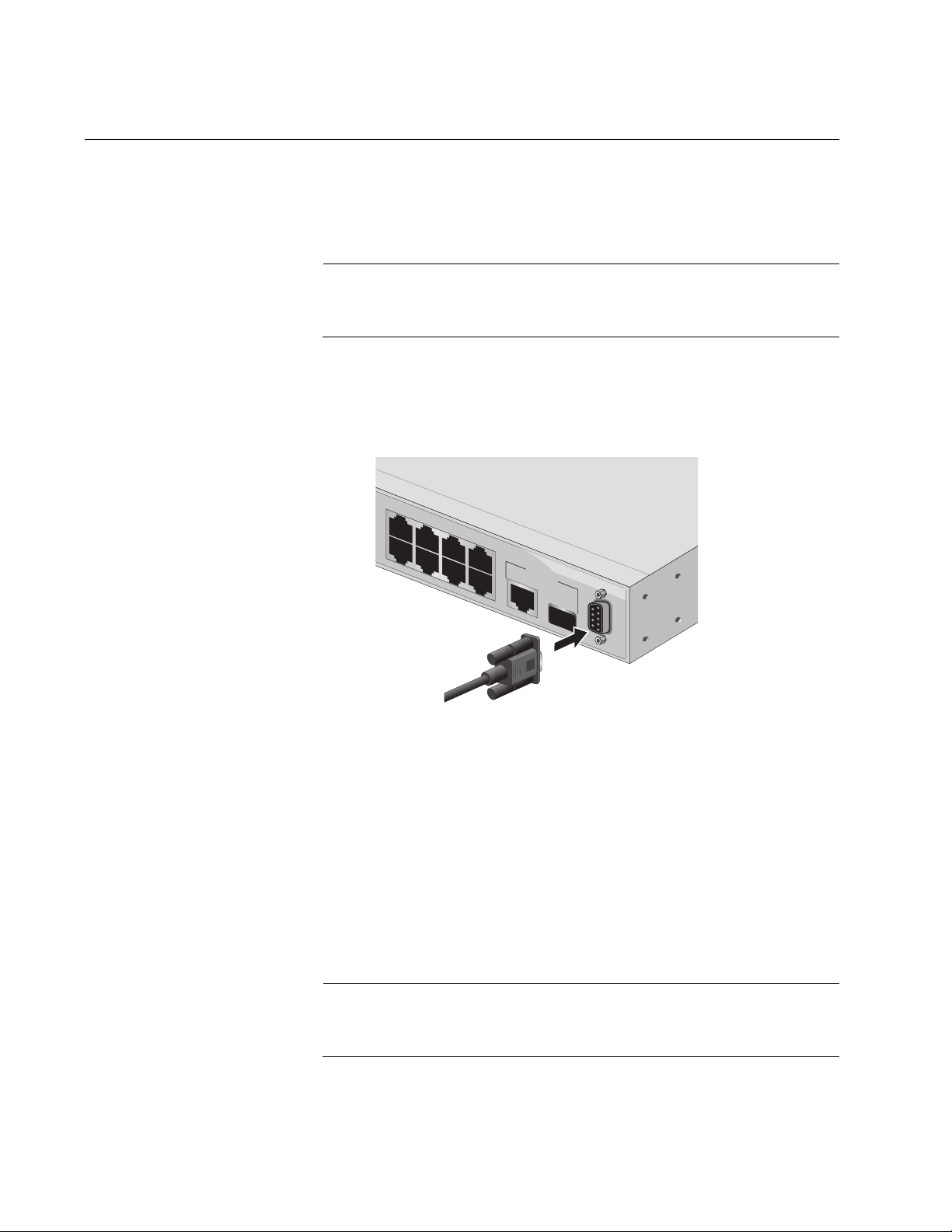
1. Connect one end of the management cable included with the switch to
the console port on the AT-8000/8POE switch, as shown in Figure 1.
13
5
2
4
6
7
UPLINK PO
10/100/1000
R
T
Ba
8
se-T
SFP
RS-232
99R
TERMINAL PORT
828
Figure 1. Connecting the Management Cable to the Console Port
2. Connect the other end of the cable to the RS-232 port on a terminal or
PC with a terminal emulator program.
3. Configure the terminal or terminal emulator program as follows:
Baud per second: 9600
Data bits: 8
Stop bits: 1
Flow control: None
Note
These settings are for a DEC VT100 or ANSI terminal, or an
equivalent terminal emulation program. You cannot change this.
26 Section I: Using the Menus Interface
Page 27

AT-S81 Management Software User’s Guide
The Login Menu is shown in Figure 2.
==============================================================
AT-8000/8POE Management System
Local - Console
Allied Telesyn International Corp.
Copyright 2005
==============================================================
Login Menu
Login:
Figure 2. Login Menu
4. Enter the manager login name and press Return. The default name is
“manager”.
You are prompted for a password.
5. Enter the manager password. The default password is “manager”.
Note
To change the login name or password, refer to “Setting the User
Interface Configuration” on page 38.
The Main Menu is shown in Figure 3.
AT-8000/8POE Local Management System
Enter the character in square brackets to select option
Main Menu
[G]eneral Information
[B]asic Switch Configuration
[A]dvanced Switch Configuration
Switch [T]ools
[C]ommand Line Interface
[S]tatistics
[Q]uit
Command>
Figure 3. Main Menu
Section I: Using the Menus Interface 27
Page 28

Chapter 2: Getting Started with the Menus Interface
Using the Menus Interface
If you are using a DEC VT00 or ANSI (the default) terminal configuration,
refer to Table 1 for instructions on how to move through the menus and
select menu options.
When directed to You must
Make a menu selection Type the menu option letter enclosed
Table 1. Menus Interface Operations
in brackets, such as typing P to select
[P]ort Configuration.
Enter information (for
example, entering a port
number)
Return to previous menu Type Q for Quit to previous menu.
When you enter a letter to select a field in which you can enter a value, a
message is displayed. For example:
Enter new password>
The “>” symbol indicates that you can enter a new value for the parameter
or change the existing value. After you have entered a value, press Enter.
Changes are immediately activated on the AT-8000/8POE switch.
Note
The web browser interface is described in Section II, “Using the Web
Browser Interface” on page 185, and the command line interface is
described in Section III, “Using the Command Line Interface” on
page 283.
Type the information and press Enter.
28 Section I: Using the Menus Interface
Page 29

Quitting from a Local Management Session
To quit a local management session, return to the Main Menu and type Q
for Quit. When you are finished managing the switch, make sure to exit
from a management session. Quitting from a local session prevents
unauthorized changes to the switch’s configuration if you leave your
workstation unattended.
Note
A local management session automatically times out if there is no
management activity during a pre-defined length of time referred to
as the timeout period. The timeout feature is intended to protect the
parameter settings on the switch from unauthorized changes should
you leave your management station unattended during a
management session. The default timeout value is 10 minutes. To
change the timeout default value, refer to “Setting the User Interface
Configuration” on page 38.
AT-S81 Management Software User’s Guide
Section I: Using the Menus Interface 29
Page 30

Chapter 2: Getting Started with the Menus Interface
30 Section I: Using the Menus Interface
Page 31

Chapter 3
Basic Switch Parameters
This chapter contains the following sections:
“Configuring the IP Address, Subnet Mask, and Gateway Address” on
page 32
“Enabling and Disabling the DHCP Client” on page 35
“Configuring System Administration Information” on page 36
“Setting the User Interface Configuration” on page 38
“Disabling or Enabling the Web Server” on page 42
“Disabling or Enabling the Telnet Server” on page 43
“Viewing Switch Information” on page 44
“Rebooting the Switch” on page 47
“Pinging a Remote System” on page 49
“Returning the AT-S81 Management Software to the Factory Default
Values” on page 52
Section I: Using the Menus Interface 31
Page 32

Chapter 3: Basic Switch Parameters
Configuring the IP Address, Subnet Mask, and Gateway Address
This procedure explains how to manually assign an IP address, subnet
mask, and gateway address to the switch. Before performing the
procedure, note the following:
An IP address and subnet mask are not required for normal network
operations of the switch. Values for these parameters are only required
if you want to remotely manage the device with a web browser.
A gateway address is only required if you want to remotely manage
the device from a remote management station that is separated from
the switch by a router.
To configure the switch to automatically obtain its IP configuration from
a DHCP server on your network, go to “Enabling and Disabling the
DHCP Client” on page 35.
To set the switch’s IP configuration, perform the following procedure:
1. From the Main Menu, type B to select Basic Switch Configuration.
The Basic Switch Configuration Menu is shown in Figure 4.
AT-8000/8POE Local Management System
Main Menu -> Basic Switch Configuration Menu
System [A]dministration Configuration
System [I]P Configuration
S[N]MP Configuration
[P]ort Configuration
[U]ser Interface Configuration
Rapid [S]panning Tree Configuration
Storm [C]ontrol Configuration
[Q]uit to previous menu
Command>
Figure 4. Basic Switch Configuration Menu
32 Section I: Using the Menus Interface
Page 33

AT-S81 Management Software User’s Guide
2. From the Basic Switch Configuration Menu, type I to select System IP
Configuration.
The System IP Configuration Menu is shown in Figure 5.
AT-8000/8POE Local Management System
Basic Switch Configuration -> System IP Configuration Menu
MAC Address: 00:06:5H:B2:65:84
IP Address: 0.0.0.0
Subnet Mask: 0.0.0.0
Gateway: 0.0.0.0
DHCP Mode: Disabled
----------------------- <COMMAND> ----------------------------Set [I]P Address
Set Subnet [M]ask
Set Default [G]ateway
Enable/Disable [D]HCP Mode
[Q]uit to previous menu
Command>
3. To set the switch’s IP address, do the following:
4. To set the switch’s subnet mask, do the following:
Figure 5. System IP Configuration Menu
The top portion of the menu displays the current IP address, subnet
mask, and gateway address for the switch. The menu also displays the
switch’s MAC address. The MAC address cannot be changed. The
menu also displays the current status of the DHCP client on the switch.
The Enable/Disable DHCP Mode option is described in “Enabling and
Disabling the DHCP Client” on page 35.
a. Type I to select Set IP Address.
The following prompt is displayed:
Enter new IP address>
b. Type the IP address for the switch and press Enter.
a. Type M to select Set Subnet Mask.
The following prompt is displayed:
Enter new subnet mask>
Section I: Using the Menus Interface 33
Page 34

Chapter 3: Basic Switch Parameters
b. Type the subnet mask for the switch and press Enter.
5. To set the switch’s gateway address, do the following:
a. Type G to select Set Default Gateway.
The following prompt is displayed:
Enter new gateway IP address>
b. Type the gateway IP address for the switch and press Enter.
34 Section I: Using the Menus Interface
Page 35

Enabling and Disabling the DHCP Client
This procedure explains how to activate and deactivate the DHCP client
on the switch. When the client is activated, the switch obtains its IP
configuration, such as its IP address and subnet mask, from a DHCP
server on your network. Before performing the procedure, note the
following:
An IP address and subnet mask are not required for normal network
operations of the switch. Values for these parameters are only required
if you want to remotely manage the device with a web browser.
The DHCP client is disabled by default on the switch.
The DHCP client does not support BOOTP servers.
To activate or deactivate the DHCP client on the switch, perform the
following procedure:
1. From the Main Menu, type B to select Basic Switch Configuration.
AT-S81 Management Software User’s Guide
The Basic Switch Configuration Menu is shown in Figure 4 on page 32.
2. From the Basic Switch Configuration Menu, type I to select System IP
Configuration.
The System IP Configuration Menu is shown in Figure 5 on page 33.
3. Type D to select Enable/Disable DHCP Mode.
The following prompt is displayed:
Enable or Disable DHCP mode (E/D)>
4. Type E to select Enable or D to select Disable.
If you enable the client, it immediately begins to send queries to the
DHCP server. It continues to send queries until it receives a response.
Section I: Using the Menus Interface 35
Page 36

Chapter 3: Basic Switch Parameters
Configuring System Administration Information
This section explains how to assign a name to the switch, as well as
specify the location of the switch and the name of the switch’s
administrator. Entering this information is optional.
To set a switch’s administration information, perform the following
procedure:
1. From the Main Menu, type B to select Basic Switch Configuration.
The Basic Switch Configuration Menu is shown in Figure 4 on page 32.
2. From the Basic Switch Configuration Menu, type A to select System
Administration Information.
The System Administration Configuration Menu is shown in Figure 6.
AT-8000/8POE Local Management System
Basic Switch Configuration -> System Admin. Configuration Menu
Description: AT-8000/8POE
ObjectID: 1.3.6.1.4.1.207.1.4
Name:
Location:
Contact:
----------------------- <COMMAND> ----------------------------Set System [N]ame
Set System [L]ocation
Set System [C]ontact Information
[Q]uit to previous menu
Command>
Figure 6. System Admin. Configuration Menu
The Description parameter in the top portion of the menu displays the
model name of the switch. The System Object ID parameter is the
numeric ID of the switch. You cannot change these parameters.
3. To set the system’s name, do the following:
a. Type N to select Set System Name.
The following prompt is displayed:
Enter system name>
36 Section I: Using the Menus Interface
Page 37

AT-S81 Management Software User’s Guide
b. Type a name for the switch (for example, Sales). The name is
optional and can contain up to 50 characters.
Note
Allied Telesyn recommends that you assign names to the switches.
Names can help you identify the switches when you manage them
and can also help you avoid performing a configuration procedure
on the wrong switch.
4. To enter the system’s location, do the following:
a. Type L to select Set System Location.
The following prompt is displayed:
Enter system location>
b. Type information to describe the location of the switch (for
instance, Third Floor). The location is optional and can contain up
to 50 characters.
5. To enter the administrator’s name, do the following:
a. Type C to select Set System Contact Information.
The following prompt is displayed:
Enter system contact>
b. Type the name of the network administrator responsible for
managing the switch. The contact name is optional and can
contain up to 50 characters.
Section I: Using the Menus Interface 37
Page 38

Chapter 3: Basic Switch Parameters
Setting the User Interface Configuration
This procedure explains how to adjust the user interface and security
features on the switch. With this procedure you can change various
settings that control user access to the switch.
To set the switch’s user interface configuration, perform the following
procedure:
1. From the Main Menu, type B to select Basic Switch Configuration.
The Basic Switch Configuration Menu is shown in Figure 4 on page 32.
2. From the Basic Switch Configuration Menu, type U to select User
Interface Configuration.
The User Interface Configuration Menu is shown in Figure 7.
AT-8000/8POE Local Management System
AT-8000/8POE Local Management System
Basic Switch Configuration -> User Interface Configuration Menu
Basic Switch Configuration -> User Interface Configuration Menu
Console UI Idle Timeout: 5 Min.
Console UI Idle Timeout: 5 Min.
Telnet UI Idle Timeout: 5 min.
Telnet UI Idle Timeout: 5 min.
Telnet Server: Enabled
Telnet Server: Enabled
SNMP Agent: Enabled
SNMP Agent: Enabled
Web Server: Enabled
Web Server: Enabled
User Name: manager
User Name: manager
----------------------- <COMMAND> -----------------------------
----------------------- <COMMAND> ----------------------------Set [C]onsole UI Time Out Enable/Disable Te[l]net Server
Set [C]onsole UI Time Out Enable/Disable Te[l]net Server
Set [T]elnet UI Time Out Enable/Disable [S]NMP Agent
Set [T]elnet UI Time Out Enable/Disable [S]NMP Agent
Change Administrator User [N]ame Enable/Disable [W]eb Server
Change Administrator User [N]ame Enable/Disable [W]eb Server
Change Administrator [P]assword [Q]uit to previous menu
Change Administrator [P]assword [Q]uit to previous menu
[R]ADIUS Server Configuration
[R]ADIUS Server Configuration
Command>
Command>
Figure 7. User Interface Configuration Menu
The Telnet server option is described in “Disabling or Enabling the
Telnet Server” on page 43.
The web server option is described in “Disabling or Enabling the Web
Server” on page 42.
38 Section I: Using the Menus Interface
Page 39

AT-S81 Management Software User’s Guide
The SNMP option is described in “Enabling or Disabling the SNMP
Agent” on page 66.
The RADIUS Server Configuration option is described Chapter 14,
“RADIUS Authentication Protocol” on page 171.
3. To configure the console UI idle time out parameter, do the following:
a. Type C to select Set Console UI Time Out.
The following prompt is displayed:
Enter console idle timeout>
b. Enter a number for the timeout value. The range is 0 to 60 minutes,
and the default is 5 minutes. A timeout value to 0 causes the switch
to never time out a local management session.
The console UI idle time out parameter specifies the length of time
a local management session can be inactive before the
management software automatically ends it. This feature prevents
unauthorized individuals from configuring the switch if you leave
your management workstation unattended.
This parameter applies to a local management session but not to a
remote SNMP or web management session. An SNMP
management session remains active as long as the network
management application is active. A web browser management
session remains active as long as your web browser is open.
Note
If you select 0, you must always remember to properly log off from a
local management session when you are finished to prevent
blocking future management sessions with the switch.
4. To configure the Telnet UI idle time out parameter, do the following:
a. Type T to select Set Telnet UI Time Out.
The following prompt is displayed:
Enter console idle timeout>
b. Enter a number for the timeout value. The range is 0 to 60 minutes,
and the default is 5 minutes. A timeout value to 0 causes the switch
to never timeout a local management session.
Section I: Using the Menus Interface 39
Page 40

Chapter 3: Basic Switch Parameters
The Telnet UI idle time out parameter specifies the length of time a
remote Telnet management session can be inactive before the
management software automatically ends it. This feature prevents
unauthorized individuals from configuring the switch if you leave
your management workstation unattended.
This parameter applies to a local management session but not to a
remote SNMP or web management session. An SNMP
management session remains active as long as the network
management application is active. A web browser management
session remains active as long as your web browser is open.
5. To change the AT-S81 management login user name, do the
following:
a. Type N to select Change Administrator User Name.
The following prompt is displayed:
Enter current password>
b. Enter the current login password. The management software
prompts you for the password to prevent an unauthorized
individual from changing the login name.
c. Type the new user name and press Enter. The default name is
“manager.” The name can be from 0 to 12 characters. Spaces are
allowed. The login name is case sensitive. Not entering a new
login name deletes the current login name without assigning a new
one.
The new user name appears in the User Field in the top portion of
the menu. You must use the new login user name the next time
you start a local or web browser management session.
6. To change the manager login password, do the following:
a. Type P to select Change Administrator Password.
The following prompt is displayed:
Enter old password>
b. Enter the current manager password and press Enter.
The following prompt is displayed:
Enter new password>
40 Section I: Using the Menus Interface
Page 41

AT-S81 Management Software User’s Guide
c. Type the new password and press Enter. The password can be
from 0 to 12 characters. Allied Telesyn recommends not using
special characters, such as spaces and exclamation points. The
password is case sensitive. Not entering a new password deletes
the current password without assigning a new one.
The following prompt is displayed:
Retype new password>
d. Retype the new password and press Enter.
You must use the new login password the next time you start a
local or remote 3management session.
Section I: Using the Menus Interface 41
Page 42

Chapter 3: Basic Switch Parameters
Disabling or Enabling the Web Server
The AT-S81 management software is shipped with web server software.
The software is available so that you can remotely manage the switch with
a web browser from any management station on your network. (The
instructions for managing a switch with a web browser are described in
Chapter 17, “Starting a Web Browser Management Session” on page
187.)
The default setting for the web server is enabled,
To disable or enable the web server, perform the following procedure:
1. From the Main Menu, type B to select Basic Switch Configuration.
The Basic Switch Configuration Menu is shown in Figure 4 on page 32.
2. From the Basic Switch Configuration Menu, type U to select User
Interface Configuration.
The User Interface Configuration Menu is shown in Figure 7 on page
38.
3. From the User Interface Configuration Menu, type W to select Enable/
Disable Web Server.
The following prompt is displayed:
Enable or Disable Web server (E/D)>
4. Type D to disable the web server or E to enable it.
42 Section I: Using the Menus Interface
Page 43

Disabling or Enabling the Telnet Server
This procedure describes how to enable or disable the Telnet server on
the switch. The default setting for the Telnet server is enabled,
To disable or enable the Telnet server, perform the following procedure:
1. From the Main Menu, type B to select Basic Switch Configuration.
The Basic Switch Configuration Menu is shown in Figure 4 on page 32.
2. From the Basic Switch Configuration Menu, type I to select User
Interface Configuration.
The User Interface Configuration Menu is shown in Figure 7 on page
38.
3. From the User Interface Configuration Menu, type L to select Enable/
Disable Telnet Server.
AT-S81 Management Software User’s Guide
The following prompt is displayed:
Enable or Disable Telnet server (E/D)>
4. Type D to disable the Telnet server or E to enable it.
Section I: Using the Menus Interface 43
Page 44

Chapter 3: Basic Switch Parameters
Viewing Switch Information
To view general information about the switch, perform the following
procedure:
1. From the Main Menu, type G to select General Information.
The General Information menu is shown in Figure 8.
AT-8000/8POE Local Management System
Main Menu -> General Information
System up for : 24min(s), 36sec(s)
Runtime Image : Version 1.0
Boot Loader : Version 1.0
Hardware Information
Version: DRAM Size: 16MB
Fixed Baud Rate: 9600bps Flash Size: 4 MB
Administration Information
Switch Name: Marketing
Switch Location: Fourth Floor
Switch Contact: Ralph
System Address Information
MAC Address: 00:06:5H:B2:65:84
IP Address: 149.35.8.237
Subnet Mask: 255.255.255.0
Gateway: 149.35.8.1
Automatic Network Features
DHCP Mode: Disabled
Press any key to continue...
Figure 8. General Information Menu
The General Information Menu displays the following information:
System up for
The number of hours, minutes, and seconds since the last reset or
power cycle.
Runtime Image
The version of the runtime software.
Boot Loader
The version of the boot loader software.
44 Section I: Using the Menus Interface
Page 45

AT-S81 Management Software User’s Guide
Hardware Information Section
Version
The hardware version number.
Fixed Baud Rate
The baud rate of the console port. You cannot change this parameter.
DRAM Size
The size of the DRAM, in megabytes.
Flash Size
The size of the flash memory, in megabytes.
Administration Information Section
Switch Name
The name assigned to the switch. To assign the switch a name, refer to
“Configuring System Administration Information” on page 36.
Switch Location
The location of the switch. To specify the location, refer to “Configuring
System Administration Information” on page 36.
Switch Contact
The contact person responsible for managing the switch. To specify
the name of a contact, refer to “Configuring System Administration
Information” on page 36.
System Address Information Section
MAC Address
The MAC address of the switch. You cannot change this information.
System IP Address
The IP address of the switch. Refer to “Configuring the IP Address,
Subnet Mask, and Gateway Address” on page 32 to manually assign
an IP address or “Enabling and Disabling the DHCP Client” on page 35
to activate the DHCP client.
Subnet Mask
The subnet mask for the switch. Refer to “Configuring the IP Address,
Subnet Mask, and Gateway Address” on page 32 to manually assign a
subnet mask or “Enabling and Disabling the DHCP Client” on page 35
to activate the DHCP client.
Gateway
Default gateway IP address. Refer to “Configuring the IP Address,
Subnet Mask, and Gateway Address” on page 32 to manually assign a
gateway address or “Enabling and Disabling the DHCP Client” on
page 35 to activate the DHCP client.
Section I: Using the Menus Interface 45
Page 46

Chapter 3: Basic Switch Parameters
Automatic Network Features Section
DHCP Mode
The status of the DHCP client on the switch. For information about
setting this parameter, refer to “Enabling and Disabling the DHCP
Client” on page 35.
2. Press any key to return to the previous menu.
46 Section I: Using the Menus Interface
Page 47

Rebooting the Switch
This procedure reboots the switch and reloads the AT-S81 management
software from flash memory. You might reboot the device if you believe it
is experiencing a problem. Rebooting the device does not change any of
the device’s parameter settings.
To reboot the switch, perform the following procedure:
1. From the Main Menu type T to select Switch Tools.
AT-S81 Management Software User’s Guide
Caution
The switch does not forward network traffic during the reboot
process. Some network traffic may be lost.
The Switch Tools Configuration Menu is shown in Figure 9.
AT-8000/8POE Local Management System
Main Menu -> Switch Tools Configuration Menu
Software [U]pgrade...
System [R]eboot
[P]ing Execution
[Q]uit to previous menu
Command>
Figure 9. Switch Tools Configuration Menu
2. From the Switch Tools Configuration Menu, type R to select System
Reboot.
Section I: Using the Menus Interface 47
Page 48

Chapter 3: Basic Switch Parameters
AT-8000/8POE Local Management System
Main Menu -> System Reboot Menu
Reboot Status: Stop
Reboot Type: Normal
---------------------- <COMMAND> ----------------------------
Set Reboot [O]ption
Start [R]eboot Process
[Q]uit to previous menu
Command>
The System Reboot Menu is shown in Figure 10.
Figure 10. System Reboot Menu
3. From the System Reboot menu, type O to select Set Reboot Option.
The following prompt is displayed:
Select reboot option (F/I/N)>
4. Type N to select Normal.
This reboot type does not change the current configuration.
Note
The F and I options are described in “Returning the AT-S81
Management Software to the Factory Default Values” on page 52.
5. Type R to select Start Reboot Process.
The following prompt is displayed:
Are you sure you want to reboot the system (Y/N)>
6. Type Y to start the reboot process or N to cancel the reboot.
The switch immediately begins to reload the AT-S81 management
software. This process takes approximately one minute to complete.
You can not manage the device during the reboot. After the reboot is
finished, you can log in again if you want to continue to manage the
device.
48 Section I: Using the Menus Interface
Page 49

Pinging a Remote System
This procedure instructs the switch to ping a node on your network. This
procedure is useful in determining whether an active link exists between
the switch and another network device. Note the following before
performing the procedure:
The switch where you are initiating the ping must have an IP address
and subnet mask.
The device you are pinging must be a member of the Default VLAN.
This means that the port on the switch through which the node is
communicating with the switch must be an untagged or tagged
member of the Default VLAN.
To ping a network device, perform the following procedure:
1. From the Main Menu, type T to select Switch Tools.
The Switch Tools Configuration Menu is shown in Figure 9 on page 47.
AT-S81 Management Software User’s Guide
2. From the Switch Tools Configuration Menu, type P to select Ping
Execution.
The Ping Execution Menu is shown in Figure 11.
AT-8000/8POE Local Management System
Switch Tools Configuration -> Ping Execution
Target IP Address: 0.0.0.0
Number of Requests: 10
Timeout Value (sec): 3
================Result=================
----------------------- <COMMAND> ----------------------------Set Target [I]P Address [E]xecute Ping
Set [N]umber of Requests [S]top Ping
Set [T]imeout Value [Q]uit to previous menu
Command>
Figure 11. Ping Execution Menu
Section I: Using the Menus Interface 49
Page 50

Chapter 3: Basic Switch Parameters
3. Type I to select Set Target IP Address.
The following prompt is displayed:
Enter new target IP address>
4. Type the IP address of the node you want the switch to ping and press
Enter.
5. Type N to select Set Number of Requests.
The following prompt is displayed:
Enter new number of requests>
6. Enter the number of ping requests you want the switch to perform. The
range is 1 to 10. The default is 10.
7. Type T to select Set Timeout Value.
The following prompt is displayed:
Enter new timeout value>
8. Enter the length of time in seconds the switch is to wait for a response
before assuming that a ping has failed. The range is 1 to 5 seconds.
The default is 3 seconds.
9. Type E to select Execute Ping.
The following prompt is displayed:
Execute ping or Clean ping data (E/C)>
10. Type E to execute the ping or C to clear previous ping data before
performing this ping.
50 Section I: Using the Menus Interface
Page 51

AT-S81 Management Software User’s Guide
Figure 12 shows an example of the results of a ping.
AT-8000/8POE Local Management System
Switch Tools Configuration -> Ping Execution
Target IP Address: 149.35.8.33
Number of Requests: 4
Timeout Value (sec): 3
================Result=================
No. 1 20 ms
No. 2 20 ms
No. 3 20 ms
No. 4 20 ms
----------------------- <COMMAND> ----------------------------Set Target [I]P Address [E]xecute Ping
Set [N]umber of Requests [S]top Ping
Set [T]imeout Value [Q]uit to previous menu
Command>
Figure 12. Ping Results
11. To stop the ping, type S to select Stop Ping.
Section I: Using the Menus Interface 51
Page 52

Chapter 3: Basic Switch Parameters
Returning the AT-S81 Management Software to the Factory Default Values
This procedure returns all AT-S81 management software parameters to
their default values and deletes all tagged and VLANs on the switch. The
AT-S81 management software default values are listed in Appendix A,
”AT-S81 Software Default Settings” on page 283.
Caution
This procedure causes the switch to reboot. The switch does not
forward network traffic during the reboot process. Some network
traffic may be lost.
To return the AT-S81 management software to the default settings,
perform the following procedure:
1. From the Main Menu, type T to select Switch Tools.
The Switch Tools Configuration Menu is shown in Figure 9 on page 47.
2. From the Switch Tools Menu, type R to select System Reboot to start
the reboot.
The System Reboot menu is shown in Figure 10 on page 48.
3. Type O to select Set Reboot Option.
The following prompt is displayed:
Select reboot option (F/I/N)>
4. Type F or I to select one of the following:
F (Factory Default)
Resets all switch parameters to the factory default settings, including
IP address, subnet mask, and gateway address.
I (Reset to Defaults Except IP Address)
Resets all switch parameters to the factory default settings, but retains
the IP address, subnet mask, and gateway settings. If the DHCP client
is enabled, it remains enabled after this reset.
Note
Option N is described in “Rebooting the Switch” on page 47.
52 Section I: Using the Menus Interface
Page 53

AT-S81 Management Software User’s Guide
5. Type R to select Start Reboot Process.
The following prompt is displayed:
Are you sure you want to reboot the system (Y/N)>
6. Type Y to start the reboot process.
The switch returns its operating parameters to the default values and
begins to reload the AT-S81 management software. This process
takes approximately one minute to complete. You can not manage the
device during the reboot. After the reboot is finished, you can log in
again if you want to continue to manage the device.
Section I: Using the Menus Interface 53
Page 54

Chapter 3: Basic Switch Parameters
54 Section I: Using the Menus Interface
Page 55

Chapter 4
Port Configuration
This chapter contains the procedures for viewing and adjusting the
parameter settings for the ports on the switch. This chapter contains the
following sections:
“Displaying the Port Parameters” on page 56
“Enabling and Disabling a Port” on page 58
“Setting a Port’s Speed and Duplex Mode” on page 59
“Changing the Flow Control Setting” on page 61
Section I: Using the Menus Interface 55
Page 56

Chapter 4: Port Configuration
Displaying the Port Parameters
To display the parameter settings for the ports on the switch, perform the
following procedure:
1. From the Main Menu, type B to select Basic Switch Configuration.
The Basic Switch Configuration Menu is shown in Figure 4 on page 32.
2. From the Basic Switch Configuration Menu, type P to select Port
Configuration.
The Port Configuration Menu is shown in Figure 13.
AT-8000/8POE Local Management System
Basic Switch Configuration -> Port Configuration Menu
Port Trunk Type Link Status Mode Flow Ctrl
---- ----- ------ ---- ------ ------------ --------1 --- 10/100TX Up Enabled Auto (100F) Enabled
2 --- 10/100TX Up Enabled Auto (100F) Enabled
3 --- 10/100TX Up Enabled 10-FDx Enabled
4 --- 10/100TX Up Enabled Auto (100F) Enabled
5 --- 10/100TX Up Enabled Auto (100F) Enabled
6 --- 10/100TX Down Enabled 100-HDx Enabled
7 --- 10/100TX Up Enabled Auto (100F) Enabled
8 --- 10/100TX Down Enabled Auto Enabled
9 --- 1000X Up Enabled Auto (1000F) Enabled
----------------------- <COMMAND> ------------------------------------
Set [S]tatus Set [F]low Control
Set [M]ode [Q]uit to previous menu
Command>
Figure 13. Port Configuration Menu
56 Section I: Using the Menus Interface
Page 57

AT-S81 Management Software User’s Guide
The Port Configuration Menu displays the following columns of
information about the status of the ports:
Port
The port number.
Trunk
The trunk group number. This column contains the number of the port
trunk if the port is a member of a trunk. To configure a trunk, refer to
Chapter 6, “Port Trunking” on page 73.
Type
The port type. The type for an RJ-45 copper port is 10/100TX. The port
type for the fiber optic ports is 1000BaseX.
Link
The status of the link between the port and the end node connected to
the port. The possible values are:
Up - A link exists between the port and the end node.
Down - The port has not established a link with an end node.
Status
The current operating status of the port. The possible values are:
Enabled - The port is able to send and receive Ethernet frames. This is
the default setting for all ports on the switch.
Disabled - The port has been manually disabled.
To change a port’s status, see “Enabling and Disabling a Port” on
page 58.
Mode
The port’s speed and duplex mode setting. For information about the
modes or to change a port’s speed and duplex mode setting, see
“Setting a Port’s Speed and Duplex Mode” on page 59.
Flow Ctrl
Whether flow control is enabled on the port. Flow control is enabled by
default. To disable flow control, refer to “Changing the Flow Control
Setting” on page 61.
Section I: Using the Menus Interface 57
Page 58

Chapter 4: Port Configuration
Enabling and Disabling a Port
This procedure enables and disables a port. You may want to disable a
port and prevent packets from being forwarded if a problem occurs with
the node or cable connected to the port. After the problem has been fixed,
you can enable the port to resume normal operation. You can also disable
an unused port to secure it from unauthorized connections. The default
setting for a port is enabled.
To change the port’s status, perform the following procedure:
1. From the Main Menu, type B to select Basic Switch Configuration.
The Basic Switch Configuration Menu is shown in Figure 4 on page 32
2. From the Basic Switch Configuration Menu, type P to select Port
Configuration.
The Port Configuration Menu is shown in Figure 13 on page 56.
3. Type S to select Set Status.
The following prompt is displayed:
Set Status->Enter port number>
4. Enter the number of the port you want to enable or disable. You can
configure only one port at a time.
The following prompt is displayed:
Enable or Disable port n (E/D)>
5. Type E to enable the port or D to disable it. The default is enabled. A
disabled port immediately stops forwarding all ingress and egress
traffic until you enable it again.
The display is refreshed to show the port’s new status.
58 Section I: Using the Menus Interface
Page 59

Setting a Port’s Speed and Duplex Mode
To change a port’s speed or duplex mode, perform the following
procedure:
1. From the Main Menu, type B to select Basic Switch Configuration.
The Basic Switch Configuration Menu is shown in Figure 4 on page 32
2. From the Basic Switch Configuration Menu, type P to select Port
Configuration.
The Port Configuration Menu is shown in Figure 13 on page 56.
3. Type M to select Set Mode.
The following prompt is displayed:
Set Mode -> Enter port number >
AT-S81 Management Software User’s Guide
4. Enter the number of the port whose speed or duplex mode you want to
change. You can configure only one port at a time.
The following prompt is displayed:
Enter new mode for port n (a/h/H/F/f/t/T)>
5. Enter the letter that corresponds to the desired speed and duplex
mode setting for the port. The port settings are:
a - Auto: The port uses Auto-Negotiation to set its speed and duplex
mode. This is the default setting for all ports.
h - 10 Mbps, half-duplex
H - 100 Mbps, half-duplex
f - 10 Mbps, full-duplex
F - 100 Mbps, full-duplex
When you select a setting, note the following:
When a twisted pair port on the switch is set to Auto-Negotiation,
the default setting, the end node should also be using AutoNegotiation to prevent a duplex mode mismatch. A switch port
using Auto-Negotiation defaults to half-duplex if it detects that the
end node is not using Auto-Negotiation. This can result in a
mismatch if the end node is operating at a fixed duplex mode of
full-duplex. To avoid this problem when connecting an end node
with a fixed duplex mode of full-duplex to a switch port, disable
Auto-Negotiation on the port and set the port’s speed and duplex
Section I: Using the Menus Interface 59
Page 60

Chapter 4: Port Configuration
mode manually.
The only valid setting for an SFP port is Auto-Negotiation.
60 Section I: Using the Menus Interface
Page 61

Changing the Flow Control Setting
Flow control applies to ports operating in full-duplex mode. A switch port
uses flow control to control the flow of ingress packets from its end node. A
port using flow control issues a special frame, referred to as a PAUSE
frame, as specified in the IEEE 802.3x standard, to stop the transmission
of data from an end node. When a port needs to stop an end node from
transmitting data, it issues this frame. The frame instructs the end node to
cease transmission. The port continues to issue PAUSE frames until it is
ready again to receive data from the end node.
To change the flow control setting on a port, perform the following
procedure:
1. From the Main Menu, type B to select Basic Configuration.
The Basic Switch Configuration Menu is shown in Figure 4 on page 32
2. From the Basic Switch Configuration Menu, type P to select Port
Configuration.
AT-S81 Management Software User’s Guide
The Port Configuration Menu is shown in Figure 13 on page 56.
3. Type F to select Flow Control.
The following prompt is displayed:
Set Flow Control -> Enter port number >
4. Enter the port number whose flow control setting you want to change.
You can configure only one port at a time.
The following prompt is displayed:
Enable or Disable flow control for port <n> (E/D)>
5. Type E to enable flow control or D to disable it. The default is enabled.
The display is refreshed to show the port’s new flow control setting.
Section I: Using the Menus Interface 61
Page 62

Chapter 4: Port Configuration
62 Section I: Using the Menus Interface
Page 63

Chapter 5
SNMP
This chapter contains the following sections:
“SNMP Overview” on page 64
“Enabling or Disabling the SNMP Agent” on page 66
“Enabling Authentication Traps” on page 67
“Changing the Default SNMP Community Names” on page 68
“Working with Trap Receivers” on page 69
Section I: Using the Menus Interface 63
Page 64

Chapter 5: SNMP
SNMP Overview
The Simple Network Management Program (SNMP) is another way for
you to manage the switch. This type of management involves viewing and
changing the management information base (MIB) objects on the device
using an SNMP application program. The AT-S81 management software
supports SNMPv1 and SNMPv2c which is always disabled on the switch.
The procedures in this chapter show you how to create and manage
SNMPv1 and SNMPv2c community strings through which your SNMP
application program at your management workstation can access the
switch’s MIB objects.
To manage a switch using an SNMP application program, you must do the
following:
Activate SNMP management on the switch. The default setting for
SNMP management is disabled. The procedure for this can be found
in “Enabling or Disabling the SNMP Agent” on page 66.
Load the Allied Telesyn MIBs for the switch onto your management
workstation containing the SNMP application program. The MIBs are
available from the Allied Telesyn web site at www.alliedtelesyn.com.
To manage a switch using SNMP, you need to know the IP address of the
switch and at least one of the switch’s community strings. A community
string is a string of alphanumeric characters that gives you access to the
switch.
A community string has several attributes that you can use to control who
can use the string and what the string will allow a network manager to do
on the switch. The community string attributes are defined below:
Community String Name
The SNMP community string is similar to a user ID or password, which
allows access to a network device’s statistics. You must assign a name to
the community string. The name can be from one to eight alphanumeric
characters. Spaces are allowed.
Access Mode
This defines what the community string will allow a network manager to
do. There are two access modes: Read and Read/Write. A community
string with an access mode of Read can only be used to view but not
change the MIB objects on a switch. A community string with a Read/Write
access can be used to both view the MIB objects and change them.
Status
A community string can be enabled, disabled, or deleted. When disabled,
no one can use it to access the switch. You might disable a community
string if you suspect someone is using it for unauthorized access to the
64 Section I: Using the Menus Interface
Page 65

AT-S81 Management Software User’s Guide
device. You can enable it again later, or even delete it. When a community
string is enabled, then it is available for use.
Trap Receivers
A trap is a signal sent to one or more management workstations by the
switch to indicate the occurrence of a particular operating event on the
device. There are numerous operating events that can trigger a trap. For
instance, resetting the switch or the failure of a cooling fan are two
examples of occurrences that cause a switch to send a trap to the
management workstations. You can use traps to monitor activities on the
switch.
Trap receivers are the devices, typically management workstations or
servers, that you want to receive the traps sent by the switch. You specify
the trap receivers by their IP addresses. You assign the IP addresses to
the community strings.
Each community string can have up to four trap IP addresses.
It does not matter which community strings you assign your trap receivers.
When the switch sends a trap, it looks at all the community strings and
sends the trap to all trap receivers on all community strings. This is true
even for community strings that have a access mode of only Read.
Default SNMP
Community
Strings
If you are not interested in receiving traps, then you do not need to enter
any IP addresses of trap receivers.
The AT-S81 management software provides two default community
strings: SNMP Read Community and SNMP Write Community. The read
community string is called “public” and has an access mode of just Read.
The write community string is named “private” and has an access mode of
write only.
Section I: Using the Menus Interface 65
Page 66

Chapter 5: SNMP
Enabling or Disabling the SNMP Agent
To disable or enable the SNMP agent, perform the following procedure:
1. From the Main Menu, type B to select Basic Switch Configuration.
The Basic Switch Configuration Menu is shown in Figure 4 on page 32.
2. From the Basic Switch Configuration Menu, type U to select User
Interface Configuration.
The User Interface Configuration Menu is shown in Figure 7 on page
38.
3. From the User Interface Configuration Menu, type S to select Enable/
Disable SNMP Agent.
The following prompt is displayed:
Enable or Disable SNMP agent (E/D)>
4. Type D to disable the SNMP agent or E to enable it. The default is
Enabled.
66 Section I: Using the Menus Interface
Page 67

Enabling Authentication Traps
To enable SNMP authentication traps, perform the following procedure:
1. From the Main Menu, type B to select Basic Switch Configuration.
The Basic Switch Configuration Menu is shown in Figure 4 on page 32.
2. From the Basic Switch Configuration menu, type N to select SNMP
Configuration.
The SNMP Configuration menu is shown in Figure 14.
AT-8000/8POE Local Management System
Basic Switch Configuration -> SNMP Configuration Menu
SNMP Read Community: public
SNMP Write Community: private
Trap Authentication: Enabled
AT-S81 Management Software User’s Guide
SNMP Trap Receivers:
No. Status IP Address Community
--- ----- -------------- -----------------------------------1 Deleted <empty> <empty>
2 Enabled 149.35.8.42 Monitor
3 Deleted <empty> <empty>
4 Deleted <empty> <empty>
-----------------------------<COMMAND>-------------------------------------Set SNMP [R]ead Community [A]dd SNMP Trap Receiver
set SNMP [W]rite Community [D]elete SNMP Trap Receiver
[M]odify SNMP Trap Receiver [E]nable/Disable Authentication Trap
Enable/Disable SNMP [T]rap Receiver [Q]uit to previous menu
Command>
Figure 14. SNMP Configuration Menu
3. Type E to select Enable/Disable Authentication Trap.
The following prompt is displayed:
Enable or Disable SNMP Authentication Trap (E/D)>
4. Type E to enable SNMP or D to disable SNMP. The default is Enabled.
Section I: Using the Menus Interface 67
Page 68

Chapter 5: SNMP
Changing the Default SNMP Community Names
To change the names of the default SNMP communities, perform the
following procedure:
1. From the Main Menu, type B to select Basic Switch Configuration.
The Basic Switch Configuration Menu is shown in Figure 4 on page 32.
2. From the Basic Switch Configuration menu, type N to select SNMP
Configuration.
The SNMP Configuration menu is shown in Figure 14 on page 67.
3. Type R to select Set SNMP Read Community.
The following prompt is displayed:
Enter read community name>
4. Type the name of the read community. The default is “public.”
5. Type W to select Set SNMP Write Community.
The following prompt is displayed:
Enter write community name>
6. Type the name of the write community. The default is “private.”
68 Section I: Using the Menus Interface
Page 69

Working with Trap Receivers
This section contains procedures for working with SNMP trap receivers
and includes the following topics:
“Adding a Trap Receiver,” next
“Enabling or Disabling Trap Receivers” on page 69
“Modifying a Trap Receiver” on page 70
“Deleting a Trap Receiver” on page 71
AT-S81 Management Software User’s Guide
Adding a Trap
Receiver
You must add a trap receiver before you can enable it.
To add a trap receiver, perform the following procedure.
1. From the Main Menu, type B to select Basic Switch Configuration.
The Basic Switch Configuration Menu is shown in Figure 4 on page 32.
2. From the Basic Switch Configuration menu, type N to select SNMP
Configuration.
The SNMP Configuration menu is shown in Figure 14 on page 67.
3. Type A to select Add SNMP Trap Receiver.
The following prompt is displayed:
Add SNMP trap receivers->Enter entry number>
4. Enter 1 through 4 for the trap receiver you want to configure.
The following prompt is displayed:
Enter IP address for trap receiver>
5. Enter the IP address of the workstation that you want to receive traps.
The following prompt is displayed:
Enter community name for trap receiver>
6. Enter a name for the workstation that you want to receive traps.
A new trap receiver is automatically enabled.
Enabling or
Disabling Trap
You can disable a trap receiver or enable one that was previously
disabled. To enable or disable a trap receiver, perform the following
procedure:
Receivers
1. From the Main Menu, type B to select Basic Switch Configuration.
Section I: Using the Menus Interface 69
Page 70

Chapter 5: SNMP
The Basic Switch Configuration Menu is shown in Figure 4 on page 32.
2. From the Basic Switch Configuration menu, type N to select SNMP
Configuration.
The SNMP Configuration menu is shown in Figure 14 on page 67.
3. Type T to select Enable/Disable SNMP Trap Receiver.
The following prompt is displayed:
Set SNMP trap receivers status->Enter entry number>
4. Enter the number of the trap receiver you want to enable or disable.
The following prompt is displayed:
Set SNMP trap receivers status->Enter entry number>
5. Enter the number for the trap you want to enable or disable.
The following prompt is displayed:
Modifying a Trap
Receiver
Enable or Disable SNMP Trap Receiver (E/D)>
Note
The trap receiver must be one whose status is not “deleted.”
6. Type E to enable the trap receiver or D for disable to disable the trap
receiver.
You can also delete a trap receiver, as described in “Deleting a Trap
Receiver” on page 71
To modify a trap receiver, perform the following procedure.
1. From the Main Menu, type B to select Basic Switch Configuration.
The Basic Switch Configuration Menu is shown in Figure 4 on page 32.
2. From the Basic Switch Configuration menu, type N to select SNMP
Configuration.
The SNMP Configuration menu is shown in Figure 14 on page 67.
3. Type M to select Modify SNMP Trap Receiver.
The following prompt is displayed:
Modify SNMP trap receivers->Enter entry number>
70 Section I: Using the Menus Interface
Page 71

AT-S81 Management Software User’s Guide
Note
The trap receiver must be one whose status is not “deleted.”
4. Enter the number for the trap you want to modify.
The following prompt is displayed:
Modify trap receiver entry number (I/C/B)>
The options are:
I - Modify the IP address of the trap receiver. To modify only the IP
address, type I and follow the prompts.
C - Modify the community name of the trap receiver. To modify only the
community name, type C and follow the prompts.
B - Modify both the IP address and community name of the trap
receiver. To modify both the IP address and the community name, type
B and follow the prompts.
Deleting a Trap
Receiver
When you delete a trap receiver, all the settings are removed from the
entry in the table. Instead of deleting a trap receiver, you may want to
disable it, as described in “Enabling or Disabling Trap Receivers” on
page 69.
To delete a trap receiver, perform the following procedure:
1. From the Main Menu, type B to select Basic Switch Configuration.
The Basic Switch Configuration Menu is shown in Figure 4 on page 32.
2. From the Basic Switch Configuration menu, type N to select SNMP
Configuration.
The SNMP Configuration menu is shown in Figure 14 on page 67.
3. Type D to select Delete SNMP Trap Receiver.
The following prompt is displayed:
Delete SNMP trap receivers->Enter entry number>
4. Type the number of the entry you want to delete.
Section I: Using the Menus Interface 71
Page 72

Chapter 5: SNMP
72 Section I: Using the Menus Interface
Page 73

Chapter 6
Port Trunking
This chapter provides information and procedures for creating a port trunk
and contains the following sections:
“Port Trunking Overview” on page 74
“Creating a Port Trunk” on page 75
“Modifying a Port Trunk” on page 78
“Enabling or Disabling a Port Trunk” on page 79
Section I: Using the Menus Interface 73
Page 74

Chapter 6: Port Trunking
Port Trunking Overview
Port trunking is an economical way for you to increase the bandwidth
between two Ethernet switches. A port trunk is 2 to 8 ports that have been
grouped together to function as one logical path. A port trunk increases
the bandwidth between switches and is useful in situations where a single
physical data link between switches is insufficient to handle the traffic
load.
A port trunk always sends packets from a particular source to a particular
destination over the same link within the trunk. A single link is designated
for flooding broadcasts and packets of unknown destination.
Port Trunking
Guidelines
Observe the following guidelines when creating a port trunk:
A port trunk can consist of up to 8 ports, but must have a minimum of 2
ports.
The switch can support up to 4 trunks at a time.
A port can belong to only one trunk at a time.
The speed, duplex mode, and flow control settings must be the same
on all the ports in a trunk.
The ports of a trunk must be members of the same VLAN. A port trunk
cannot consist of ports from different VLANs.
The ports of a trunk do not have to be consecutive.
When you cable a trunk, the order of the connection should be
maintained on both nodes. The lowest numbered port in a trunk on the
switch should be connected to the lowest numbered port of the trunk
on the other device, the next lowest numbered port on the switch
should be connected to the next lowest numbered port on the other
device, and so on.
For example, assume that you are connecting a trunk between two
AT-8000/8POE switches. On the first AT-8000/8POE switch you select
ports 1 through 4 for a trunk. On the second AT-8000/8POE switch you
select ports 5 through 8. To maintain the order of the port connections,
connect port 1 on the first AT-8000/8POE switch to port 5 on the
second AT-8000/8POE switch, port 2 to port 6, and so on.
To avoid compatibility problems, Allied Telesyn recommends creating a
port trunk only between AT-8000/8POE switches. A port trunk between
an AT-8000/8POE switch and a device from another manufacturer
might result in undesirable trunk behavior.
74 Section I: Using the Menus Interface
Page 75

Creating a Port Trunk
This procedure explains how to create a port trunk.
To create a port trunk, perform the following procedure:
1. From the Main Menu, type A to select Advanced Switch
Configuration.
The Advanced Switch Configuration Menu is shown in Figure 15.
AT-S81 Management Software User’s Guide
Caution
Do not connect the cables to the ports on the switches until after you
have configured the trunk with the management software.
Connecting the cables before configuring the software creates a
loop in your network topology, which can result in broadcast storms
and poor network performance.
AT-8000/8POE Local Management System
Main Menu -> Advanced Switch Configuration Menu
[V]LAN Management
[T]runk Configuration
[I]GMP Snooping Configuration
Quality of [S]ervice Configuration
Port [M]irroring Configuration
802.x[X] Port Based Access Control Configuration
Power Over [E]thernet Configuration
[Q]uit to previous menu
Command>
Figure 15. Advanced Switch Configuration Menu
2. From the Advanced Switch Configuration Menu, type T to select Trunk
Configuration.
Section I: Using the Menus Interface 75
Page 76

Chapter 6: Port Trunking
AT-8000/8POE Local Management System
Advanced Switch Configuration -> Trunk Configuration Menu
Group Status Port Members Trunk ID
------- -------------- --------------------- ---------1 Disabled 1
2 Disabled 2
3 Disabled 3
4 Disabled 4
5 Disabled 5
6 Disabled 6
7 Disabled 7
----------------------- <COMMAND> -----------------------------
[A]dd Trunk Member [S]et Trunk Status
[R]emove Trunk Member [Q]uit to previous menu
The Trunk Configuration Menu is shown in Figure 16.
Command>
Figure 16. Trunk Configuration Menu
3. To add a trunk member, do the following:
a. From the Trunk Configuration Menu, type A to select Add Trunk
Member.
The following prompt is displayed:
Enter trunk group number>
b. Select a trunk group number from 1 to 4 and press Enter.
The following prompt is displayed:
Enter port members (up to 8 ports) for trunk
c. Enter the ports you want to include in the trunk and press Enter.
You can specify the ports individually separated by commas (for
example, 1,2,5), as a range of ports separated by a hyphen (for
example, 2-4), or both (for example, 1,3, 6-8).
n
>
4. To set the trunk status, do the following:
a. Type S to select Set Trunk Status.
The following prompt is displayed:
76 Section I: Using the Menus Interface
Page 77

AT-S81 Management Software User’s Guide
Enter trunk group number>
b. Type the trunk group number and press Enter.
The following prompt is displayed:
n
Enable or Disable trunk group number
(E/D)>
c. Type E to enable the trunk.
The trunk is now operational on the switch.
5. Configure the port trunk on the other switch and connect the cables.
Section I: Using the Menus Interface 77
Page 78

Chapter 6: Port Trunking
Modifying a Port Trunk
This procedure adds and removes ports from a port trunk.
Note
You should disconnect the cables from the ports of the trunk on the
switch before modifying it. Adding or removing ports from a trunk
without first disconnecting the cables can create loops in your
network topology, which can cause broadcast storms and poor
network performance.
To add or remove ports from a trunk, perform the following procedure:
1. From the Main Menu, type A to select Advanced Switch
Configuration.
The Advanced Switch Configuration Menu is shown in Figure 15 on
page 75.
2. From the Advanced Switch Configuration Menu, type T to select
Trunk Configuration.
The Trunk Configuration Menu is shown in Figure 16 on page 76.
3. To add ports to a port trunk, type A to select Add Trunk Member. To
remove ports, type R to select Remove Trunk Member.
The following prompt is displayed:
Enter trunk group number>
4. Type the number of the trunk group you want to modify and press
Enter.
The following prompt is displayed:
Enter port members (up to 8 ports) for trunk n>
5. Enter the ports you want to add or remove from the trunk and press
Enter.
You can specify the ports individually, separated by commas (for
example, 1,2,5), as a range of ports separated by a hyphen (for
example, 2-4), or both (for example, 1,3, 6-8).
6. Modify the port trunk on the other switch and reconnect the cables.
78 Section I: Using the Menus Interface
Page 79

Enabling or Disabling a Port Trunk
This procedure enables and disables a port trunk. Note the following
before performing this procedure:
Do not enable a port trunk until after you have configured the trunk on
both switches.
Do not connect the cables to the ports on the switches until after you
have configured and enabled the trunk on both switches.
Note
If you are disabling a port trunk, be sure to first disconnect all cables
from the ports of the trunk. Leaving the cables connected can create
loops in your network topology because the ports of a disabled port
trunk function as normal network ports, forwarding individual
network traffic.
AT-S81 Management Software User’s Guide
To enable or disable a port trunk, perform the following procedure:
1. From the Main Menu, type A to select Advanced Switch
Configuration.
The Advanced Switch Configuration Menu is shown in Figure 15 on
page 75.
2. From the Advanced Switch Configuration Menu, type T to select Trunk
Configuration.
The Trunk Configuration Menu is shown in Figure 16 on page 76.
3. From the Trunk Configuration Menu, type S to select Set Trunk
Status.
The following prompt is displayed:
Enter trunk group number>
4. Type the number of the trunk group you want to enable or disable and
press Enter.
The following prompt is displayed:
Enable or Disable trunk group number n (E/D)>
5. Type E to enable the trunk or D to disable it.
Section I: Using the Menus Interface 79
Page 80

Chapter 6: Port Trunking
80 Section I: Using the Menus Interface
Page 81

Chapter 7
Port Mirroring
This chapter contains the procedure for setting up port mirroring. Port
mirroring allows you to unobtrusively monitor the ingress and egress traffic
on a port by having the traffic copied to another port. This chapter contains
the following sections:
“Port Mirroring Overview” on page 82
“Configuring Port Mirroring” on page 83
“Enabling or Disabling Port Mirroring” on page 85
Section I: Using the Menus Interface 81
Page 82

Chapter 7: Port Mirroring
Port Mirroring Overview
The port mirroring feature allows you to unobtrusively monitor the ingress
and egress traffic on a port on the switch by having the traffic copied to
another switch port. By connecting a network analyzer to the port where
the traffic is being copied to, you can monitor the traffic on the other port
without impacting its performance or speed.
The port whose traffic you want to mirror is called the mirrored port. The
port where the traffic will be copied to is called the mirroring port.
Observe the following guidelines when using this feature:
You can mirror only one port at a time.
The mirrored and mirroring ports must be on the same switch.
This feature copies both the ingress and egress traffic of the mirrored
port.
The mirroring port cannot be used for normal Ethernet switching.
82 Section I: Using the Menus Interface
Page 83

Configuring Port Mirroring
To set up port mirroring, perform the following procedure:
1. From the Main Menu, type A to select Advanced Switch
Configuration.
The Advanced Switch Configuration Menu is shown in Figure 15 on
page 75.
2. From the Advanced Switch Configuration Menu, type M to select Port
Mirroring Configuration.
The Port Mirroring Configuration Menu is shown in Figure 17.
AT-8000/8POE Local Management System
Advanced Switch Configuration -> Port Mirroring Configuration Menu
Mirroring Port Mirrored Port Status
--------------- -------------- -----2 1 Disabled
AT-S81 Management Software User’s Guide
----------------------- <COMMAND> -----------------------------
[S]et Mirroring Port
Set [M]irrored Port
[E]nable/Disable Port Mirroring
[Q]uit to previous menu
Command>
Figure 17. Port Mirroring Menu
3. Type S to select Set Mirroring Port.
The following prompt is displayed:
Set monitoring port-> Enter port number>
4. Type the number of the port where the network analyzer is connected
and press Enter. You can specify only one port.
5. Type M to select Set Mirrored Port.
The following prompt is displayed:
Set monitored port-> Enter port number>
6. Type the number of the port whose ingress and egress traffic you want
to monitor and press Enter. You can specify only one port.
Section I: Using the Menus Interface 83
Page 84

Chapter 7: Port Mirroring
7. Type E to select Enable/Disable Port Mirroring.
The following prompt is displayed:
Enable or Disable monitoring (E/D)>
8. Type E to enable port mirroring.
You can now connect your data analyzer to the mirroring port.
84 Section I: Using the Menus Interface
Page 85

Enabling or Disabling Port Mirroring
To enable or disable port mirroring, perform the following procedure:
1. From the Main Menu, type A to select Advanced Switch
Configuration.
The Advanced Switch Configuration Menu is shown in Figure 15 on
page 75.
2. From the Advanced Switch Configuration Menu, type M to select Port
Mirroring Configuration.
The Port Mirroring Menu is shown in Figure 17 on page 83.
3. Type E to select Enable/Disable Port Mirroring.
The following prompt is displayed:
AT-S81 Management Software User’s Guide
Enable or Disable monitoring (E/D)>
4. Type E to disable port mirroring or D to disable port mirroring. Port
mirroring is disabled by default.
When you disable port mirroring, the port that was functioning as the
mirroring port can then be used as a normal networking port.
Section I: Using the Menus Interface 85
Page 86

Chapter 7: Port Mirroring
86 Section I: Using the Menus Interface
Page 87

Chapter 8
Power Over Ethernet
This chapter contains the following sections:
“PoE Overview” on page 88
“Configuring PoE” on page 91
Section I: Using the Menus Interface 87
Page 88

Chapter 8: Power Over Ethernet
PoE Overview
The twisted pair ports on the AT-8000/8POE Fast Ethernet Switch feature
Power over Ethernet (PoE). PoE is a mechanism for supplying power to
network devices over the same twisted pair cables used to carry network
traffic. This feature can simplify network installation and maintenance by
allowing you to use the switch as a central power source for other network
devices.
A device that receives its power over an Ethernet cable is called a
powered device. Examples of such devices can be wireless access points,
IP telephones, webcams, and even other Ethernet switches. An example
of the latter is the unmanaged AT-FS705PD Ethernet switch from Allied
Telesyn. A powered device connected to a port on the switch will receive
both network traffic and power over the same twisted pair cable.
The switch automatically determines whether a device connected to a port
is a powered device or not. A powered device has a signature resistor or
signature capacitor that the switch can detect over the Ethernet cabling. If
the resistor or capacitor is present, the switch assumes that the device is a
powered device.
Note
The uplink ports (9 and 9R) do not provide PoE.
Power Budgeting A port on the switch connected to a powered device can supply up to 15.4
watts of power to the device, while at the same time furnishing standard
10/100 Mbps Ethernet functionality. A port connected to a network node
that is not a powered device (that is, a device that receives its power from
another power source) functions as a regular Ethernet port, without PoE.
The PoE feature remains enabled on the port but no power is delivered to
the device.
The AT-8000/8POE Fast Ethernet Switch can provide up to a total of 95
watts (W) of PoE power and a maximum of 15.4 W per port.
Port
Prioritization for
Power Allocation
The AT-S81 management software also allows you to prioritize the ports
in the event that the powered devices require more power than the switch
can deliver. This feature ensures that the most important powered devices
connected to the switch are guaranteed to have power.
If the powered devices connected to the switch require more power than
the switch is capable of delivering, the switch denies power to some ports
based on a system called port prioritization. You can use this system to
ensure that powered devices that are critical to your network are given
preferential access to the available power.
88 Section I: Using the Menus Interface
Page 89

AT-S81 Management Software User’s Guide
There are three priority levels:
Critical
High
Low
Ports designated as critical receive power before any other ports with a
lower priority. Always assign the critical priority level to your most
important network devices. If there is not enough power to support all the
ports set to the critical priority level, then power is provided to the ports
based on port number, in ascending order.
Ports set to the high level receive power only after all the critical ports
receive their power. If there is not enough power to support all the ports
set to the high priority level, then power is provided to the ports based on
port number, in ascending order.
The lowest priority setting is low, the default setting for all ports. Ports with
low priority receive power only after the critical and high level ports receive
their power. If there is not enough power to support all the ports set to the
high priority level, then power is provided to the ports based on port
number, in ascending order.
PoE Device
Classes
Power allocation is dynamic. Ports supplying power to powered devices
may cease power transmission if the switch’s power budget has reached
maximum usage and new powered devices, connected to ports with a
higher priority, become active.
The IEEE 802.3af standard specifies four classes for powered devices
based on their power usage. The classes are defined in Table 2.
Table 2. Power Classes for Powered Devices
Class Power Usage
0 (Default) 0.44 W to 12.95 W
1 0.44 W to 3.84 W
2 3.84 W to 6.49 W
3 6.49 W to 12.95 W
Note
The standard specifies five classes, but the fifth is reserved for
future use.
Manufacturers set the power class of their PoE powered devices. You
cannot adjust this. You can view the power class of each device in the
Section I: Using the Menus Interface 89
Page 90

Chapter 8: Power Over Ethernet
Power Over Ethernet menu, shown in Figure 18 on page 91.
Even though each port is capable of supplying up to 15.4 W, the standard
calls for a maximum power consumption of 12.95 W, 2.45 W less than the
port can supply. This extra capability is to compensate for possible line
loss. Some power is likely to be lost on the twisted pair cable as it travels
from the switch to the device. For devices that require 12.95 W, the extra
watts act as compensation for this possible loss.
90 Section I: Using the Menus Interface
Page 91

Configuring PoE
AT-S81 Management Software User’s Guide
This section contains the following procedures:
“Displaying the PoE Configuration,” next
“Changing the PoE Port’s Admin Setting” on page 92
“Setting the PoE Port’s Priority” on page 93
Displaying the
PoE
Configuration
To display the current PoE Configuration, perform the following procedure:
1. From the Main Menu, type A to select Advanced Switch
Configuration.
The Advanced Switch Configuration Menu is shown in Figure 15 on
page 75.
2. From the Advanced Switch Configuration menu, type E to select
Power Over Ethernet.
The Power Over Ethernet menu is shown in Figure 18.
AT-8000/8POE Local Management System
Advanced Switch Configuration -> Power Over Ethernet Menu
Power Budget : 95W
Power Consumption : 40W
NO. Admin Status Class Priority Pow.(mW) Vol.(V) Cur.(mA)
--- ----- -------------- ----- -------- -------- ------- -------1 Up Powered 0 High 7109 69 103
2 Up Not Powered 0 Low 0 0 0
3 Down Not Powered 0 Low 0 0 0
4 Up Not Powered 0 Low 0 0 0
5 Up Powered 0 Critical 2006 0 0
6 Up Not Powered 0 Low 0 0 0
7 Up Not Powered 0 Low 0 0 0
8 Up Not Powered 0 Low 0 0 0
-----------------------------<COMMAND>----------------------------------Set PoE Port Admin [S]tatus Set PoE Port Pr[i]ority
[Q]uit to previous menu
Command>
Figure 18. Power Over Ethernet Menu
Section I: Using the Menus Interface 91
Page 92

Chapter 8: Power Over Ethernet
The Power Over Ethernet Configuration menu displays information
about the PoE status of each port and also allows you to configure the
port’s status and priority. The table includes the following items of
information:
Admin
The status of the port, either up or down. To change the Admin
selection, refer to “Changing the PoE Port’s Admin Setting” on
page 92.
Status
Whether a PoE device is being powered or not by that port. “Powered”
means that the port is providing power to a powered device. “Not
Powered” indicates that the device is not a powered device or that no
device is connected to the port. You cannot alter this setting.
Class
The IEEE 802.3af class of the device. You cannot change this setting.
For more information, refer to “PoE Device Classes” on page 89.
Priority
The port’s priority for receiving power from the switch. For more
information about port priority, refer to “Port Prioritization for Power
Allocation” on page 88. To set the priority, refer to “Setting the PoE
Port’s Priority” on page 93.
Changing the
PoE Port’s
Admin Setting
Power (mW)
The amount of power being delivered to the device, in Milliwatts.
Voltage (V)
The amount of voltage being delivered to the device, in Volts.
Current (mA)
The amount of current being delivered to the device, in Milliamps.
To change a port’s admin setting from up (online) to down (offline),
perform the following procedure:
1. Type S to select Set PoE Port Admin Status.
The following prompt is displayed:
Enter port number >
2. Enter the number of the port you whose status you want to change.
The following prompt is displayed:
Up or Down port n (U/D) >
3. Type U to change the status to Up (online), or type D to change the
status to Down (offline).
92 Section I: Using the Menus Interface
Page 93

AT-S81 Management Software User’s Guide
Setting the PoE
Port’s Priority
The priority defines which port and its attached PoE powered device
should receive priority for the available power over other PoE devices. For
more information about port priority, refer to “Port Prioritization for Power
Allocation” on page 88.
To set the port priority, perform the following procedure:
1. Type I to select Set PoE Port Priority.
The following prompt is displayed:
Enter port number >
2. Enter the number of the port you whose priority you want to change.
The following prompt is displayed:
Enter the selection (L/H/C) >
3. Type one of the following:
L - To change the port priority to low. This is the default.
H - To change the port priority to high.
C - To change the port priority to critical.
Section I: Using the Menus Interface 93
Page 94

Chapter 8: Power Over Ethernet
94 Section I: Using the Menus Interface
Page 95

Chapter 9
Virtual LANs
This chapter contains the procedures for creating, modifying, and deleting
and tagged Virtual Local Area Networks (VLANs). This chapter contains
the following sections:
“VLAN Features” on page 96
“VLAN Overview” on page 98
“Creating a VLAN” on page 105
“Configuring the Port PVID” on page 108
“Displaying the VLANs” on page 110
“Modifying a VLAN” on page 112
“Deleting a VLAN” on page 114
“Resetting to the Default VLAN” on page 115
Section I: Using the Menus Interface 95
Page 96

Chapter 9: Virtual LANs
VLAN Features
A Virtual Local Area Network (VLAN) is a logical grouping of devices on
different physical LAN segments that allows users to communicate as if
they were physically connected to a single LAN, independent of the
physical configuration of the network.
With VLANs, you can segment your network and group end-nodes with
related functions into their own separate, logical LAN segments. For
example, the marketing personnel in your company may be spread
throughout a building. Assigning marketing to a single VLAN allows
marketing personnel to share resources and bandwidth as if they were
connected to the same segment. The resources of other departments can
be visible to the marketing VLAN members, accessible, or accessible only
to specified individuals.
A few benefits of a VLAN architecture are described in the following
sections.
Increased
Performance
Improved
Manageability
Increased
Security
In traditional Layer 2 switched networks, broadcast packets are sent to
each and every individual port. Grouping users into logical networks limits
broadcast traffic to users performing similar functions or users within
individual workgroups. High traffic, the danger of broadcast storms, router
latency, and data collisions are significantly reduced, and the efficiency of
the entire network is improved.
VLANs provide a fundamental improvement in the design, administration,
and management of LANs. Before VLANs, physical changes to a network
were made at the switch in the wiring closet.
For example, if an employee transferred to a new department, changing
that employee’s LAN segment assignment often required a physical wiring
change at the switch.
As a software-base solution, VLANs eliminate the restriction of existing
network design and cabling infrastructure and allow the centralized
configuration of switches located in many different locations. VLAN
memberships are changed quickly and efficiently from the management
console rather than in a wiring closet.
VLANs provide additional security not available in a shared media network
environment. Because a switched network only delivers frames to
intended recipients, and only broadcast frames to other members of the
VLAN, a network administrator can segment users requiring access to
sensitive information into separate VLANs from the rest of the general
user community.
96 Section I: Using the Menus Interface
Page 97

AT-S81 Management Software User’s Guide
VLANs can be used to control the flow of data in your network, since the
traffic generated by an end-node in a VLAN is restricted to the other endnodes in the same VLAN. In addition, VLANs can prevent data from
flowing to unauthorized end-nodes
Section I: Using the Menus Interface 97
Page 98

Chapter 9: Virtual LANs
VLAN Overview
This VLAN overview contains the following sections:
“VLAN Name,” next
“VLAN Identifier” on page 98
“VLAN Port Members” on page 98
“Port VLAN Identifier” on page 98
“Incoming and Outgoing Tagged and Untagged Frames” on page 99
“Guidelines for Creating a VLAN” on page 100
VLAN Name To create a port-based VLAN, you must give it a name. The name should
reflect the function of the network devices that are be members of the
VLAN. Examples include Sales, Production, and Engineering.
VLAN Identifier Every VLAN in a network must have a unique number assigned to it. This
number is called the VLAN identifier (VID). This number uniquely identifies
a VLAN in the switch and the network. The factory VID is 1 for all ports.
Port VLAN
Identifier
VLAN Port
Members
If a VLAN consists only of ports located on one physical switch in your
network, you assign it a VID different from all other VLANs in your
network.
If a VLAN spans multiple switches, then the VID for the VLAN on the
different switches should be the same. The switches are then able to
recognize and forward frames belonging to the same VLAN even though
the VLAN spans multiple switches.
For example, if you had a VLAN titled Marketing that spanned three
AT-8000/8POE Fast Ethernet switches, you would assign the Marketing
VLAN on each switch the same VID.
The Port VLAN Identifier (PVID) is the VLAN identifier associated with a
specific port. The PVID provides a VLAN assignment for each untagged
frame received by the switch. (See “Incoming and Outgoing Tagged and
Untagged Frames” on page 99.) The switch internally associates the
untagged frame with the VID that is equal to the PVID. The switch then
forwards this frame to one of the other member ports of that VLAN. The
default PVID value is 1.
You need to specify which ports on the switch are to be members of a
VLAN. A port can be specified as a member of one or more VLANs up to
255, the maximum number of VLANs supported by the switch. The factory
default VID is 1. Therefore, each port is initially configured to be a member
of VLAN 1, which is known as the default VLAN.
98 Section I: Using the Menus Interface
Page 99

AT-S81 Management Software User’s Guide
Note
The switch is preconfigured with the Default_VLAN only. All ports on
the switch are initially members of the Default_VLAN.
If a port is assigned to be a new member of a VLAN, its membership can
be defined as either tagged or untagged.
Tagged Port Members
A port is a tagged member of a VLAN when the PVID does not equal the
VID. In this case, the port must be a member of two or more VLANs. If a
port is a tagged member of one VLAN, then the same port is also an
untagged member of another VLAN where the PVID matches its VID.
Untagged Port Members
A port is an untagged member of a VLAN if the PVID is equal to the VID of
that VLAN. A port can be an untagged member of only one VLAN. An
example of this is the Default_VLAN configuration where all ports are
initially configured to be untagged members of VLAN 1 only. A port can be
an untagged member of one VLAN and be a tagged member of one or
more VLANS at the same time. (See Figure 20 on page 103.)
Incoming and
Outgoing Tagged
and Untagged
Frames
The VLAN information within an Ethernet frame is referred to as a tag or
tagged header. An Ethernet frame can contain VLAN information within its
header. Likewise, a frame that does not contain this VLAN tag information
is referred to as an untagged or standard frame. A tag contains the VID
information of the VLAN to which the frame belongs, according to the
IEEE802.1Q VLAN tagging standard.
When a switch receives a frame, it examines the frame header to see if it
contains a VLAN tag (tagged frame) or no tag (untagged frame). After
switching the frame to an outgoing port and before transmitting it, the
switch determines if the tag information should be kept in the header or
should be stripped out and made into an untagged frame.
Incoming Frames
Tagged frames received by the switch are only accepted (not dropped or
discarded) if the tag information contained in the frame is equal to one of
the VIDs of which the port is a member. If the tag information contained in
the frame does not match one of these VIDs, the frames are dropped or
discarded.
Untagged frames received by the switch are always accepted by all ports
on the switch. As described in “Port VLAN Identifier” on page 98, each
untagged frame received by the switch is assigned a VLAN number equal
to the PVID. The switch then forwards this frame to one of the other
member ports of that VLAN.
Section I: Using the Menus Interface 99
Page 100

Chapter 9: Virtual LANs
Outgoing Frames
Frames being transmitted from the switch retain their VLAN tag
information in the frame header if the frame’s tag does not match the PVID
of the port (a tagged member of that VLAN). These frames are untagged
after transmission from the switch.
The VLAN tag information in the header of the frame is stripped from the
frame’s header if the tag matches the PVID of the port (an untagged
member of the VLAN). These frames are untagged after transmission from
the switch.
Guidelines for
Creating a VLAN
The following are guidelines for creating a VLAN.
Each VLAN must be assigned a unique VID. If a particular VLAN
spans multiples switches, each part of the VLAN on the different
switches should be assigned the same VID.
A port can be an untagged member of only one VLAN at a time.
Each port must be assigned a PVID (the default is 1). This value must
match one of the VIDs assigned to the port. If you need to change the
PVID value, you must configure it on a port after you assign a port to a
VLAN. For instructions, refer to “Configuring the Port PVID” on
page 108.
A VLAN that spans multiple switches requires a port on each switch
where the VLAN is located to function as an interconnection between
the switches where the various parts of the VLAN reside.
This port may be defined as an untagged member of a VLAN where
the port is connected to another switch via another untagged port
member of the VLAN. This means that all traffic on this inter-switch
port contains traffic for that VLAN only. See figure???
Another scenario is where the port could be an untagged member of
one VLAN and a tagged member of one or more VLANs. The port
would then be connected to another switch via a port with the same
VLAN membership. This means that the traffic on this inter-switch port
is for any or all of the VLANs of which the port is a member.
If there are end nodes in different VLANs that need to communicate
with each other, a router or Layer 3 switch is required to interconnect
the VLANs.
The switch can support up to a total of 255 VLANs.
100 Section I: Using the Menus Interface
 Loading...