

Page 1

Management
Software
AT-S80
User’s Guide
For use with the AT-FS750/16 and
AT-FS750/24 Fast Ethernet Smart
Switches
Version 2.0.0
613-000213 Rev. C
Page 2

Copyright 2008 Allied Telesis, Inc.
All rights reserved. No part of this publication may be reproduced without prior written permission from Allied Telesis, Inc.
Allied Telesis and the Allied Telesis logo are trademarks of Allied Telesis, Incorporated. All other product names, company names, logos or
other designations mentioned herein are trademarks or registered trademarks of their respective owners.
Allied Telesis, Inc. reserves the right to make changes in specifications and other information contained in this document without prior
written notice. The information provided herein is subject to change without notice. In no event shall Allied Telesis, Inc.be liable for any
incidental, special, indirect, or consequential damages whatsoever, including but not limited to lost profits, arising out of or related to this
manual or the information contained herein, even if Allied Telesis, Inc. has been advised of, known, or should have known, the possibility of
such damages.
Page 3

Contents
Preface ............................................................................................................................................................ 13
Where to Find Web-based Guides ................................................................................................................... 14
Document Conventions .................................................................................................................................... 15
Contacting Allied Telesis .................................................................................................................................. 16
Online Support ........................................................................................................................................... 16
Email and Telephone Support.................................................................................................................... 16
Warranty..................................................................................................................................................... 16
Returning Products .................................................................................................................................... 16
Sales or Corporate Information.................................................................................................................. 16
Management Software Updates................................................................................................................. 16
Chapter 1: Overview ...................................................................................................................................... 17
Management Overview..................................................................................................................................... 18
Local Management Connection ................................................................................................................. 19
Remote Management Connection ............................................................................................................. 19
Remote SNMP Management............................................................................................................................ 20
Management Access Level .............................................................................................................................. 21
Ports 17 and 18 on the AT-FS750/16 Switch and Ports 25 and 26 on the AT-FS750/24 Switch ..................... 22
Using the Menus Interface ........................................................................................ 23
Chapter 2: Getting Started with the Menus Interface ................................................................................. 25
Starting a Local Management Session............................................................................................................. 26
Using the Menus Interface................................................................................................................................ 28
Quitting from a Local Management Session..................................................................................................... 29
Chapter 3: Basic Switch Parameters ........................................................................................................... 31
Configuring the IP Address, Subnet Mask, and Gateway Address .................................................................. 32
Enabling and Disabling the DHCP Client ......................................................................................................... 35
Configuring System Administration Information ............................................................................................... 36
Setting the User Interface Configuration .......................................................................................................... 38
Viewing Switch Information .............................................................................................................................. 43
Rebooting the Switch........................................................................................................................................ 46
Pinging a Remote System ................................................................................................................................ 48
Returning the AT-S80 Management Software to the Factory Default Values .................................................. 51
Chapter 4: Port Configuration ...................................................................................................................... 53
Displaying the Port Parameters........................................................................................................................ 54
Enabling and Disabling a Port .......................................................................................................................... 56
Setting a Port’s Speed and Duplex Mode......................................................................................................... 57
Changing the Flow Control Setting................................................................................................................... 59
Chapter 5: Port Trunking .............................................................................................................................. 61
Port Trunking Overview .................................................................................................................................... 62
Port Trunking Guidelines............................................................................................................................ 62
Creating a Port Trunk ....................................................................................................................................... 64
3
Page 4

Contents
Modifying a Port Trunk...................................................................................................................................... 67
Enabling and Disabling a Port Trunk ................................................................................................................69
Chapter 6: IGMP Snooping ...........................................................................................................................71
IGMP Snooping Overview.................................................................................................................................72
Configuring IGMP Snooping ............................................................................................................................. 74
Enabling or Disabling IGMP Snooping ....................................................................................................... 74
Setting the Age-out Timer........................................................................................................................... 76
Setting Group Members ............................................................................................................................. 76
Chapter 7: Static Multicast Address ............................................................................................................. 79
Static Multicast Address Overview.................................................................................................................... 80
Creating a Static Multicast Address ..................................................................................................................81
Adding a Static Multicast Address .............................................................................................................. 81
Deleting a Static Group .............................................................................................................................. 82
Deleting a Static Member Port.................................................................................................................... 83
Chapter 8: Port Mirroring .............................................................................................................................. 85
Port Mirroring Overview ....................................................................................................................................86
Configuring Port Mirroring ................................................................................................................................. 87
Enabling or Disabling Port Mirroring .................................................................................................................89
Chapter 9: Dial-in User Configuration .......................................................................................................... 91
Dial-in User Configuration Overview ................................................................................................................. 92
Configuring a Dial-in User .................................................................................................................................93
Adding a Dial-in User.................................................................................................................................. 93
Deleting a Dial-in User................................................................................................................................ 94
Modifying a
Dial-in User .......................................................................................................................................................95
Chapter 10: Virtual LANs ...............................................................................................................................97
VLAN Overview................................................................................................................................................. 98
Port-based VLAN Overview ............................................................................................................................ 100
VLAN Name.............................................................................................................................................. 100
Group ID ................................................................................................................................................... 100
General Rules for Creating a Port-based VLAN .......................................................................................100
Tagged VLAN Overview .................................................................................................................................101
Tagged and Untagged Ports .................................................................................................................... 101
Port VLAN Identifier.................................................................................................................................. 102
General Rules for Creating a Tagged VLAN ............................................................................................ 102
Creating a VLAN .............................................................................................................................................103
Configuring the PVID of Untagged Ports ........................................................................................................ 107
Changing the PVID................................................................................................................................... 109
Changing Port VLAN Type ....................................................................................................................... 110
Displaying the VLANs .....................................................................................................................................111
Resetting a VLAN to the Default Value ........................................................................................................... 113
Modifying a VLAN ........................................................................................................................................... 114
Deleting a VLAN .............................................................................................................................................116
Deleting a Port-based VLAN .................................................................................................................... 116
Deleting a Tagged VLAN..........................................................................................................................117
Chapter 11: Simple Network Management Protocol (SNMP)
................................................................... 119
SNMP Overview.............................................................................................................................................. 120
Community String Attributes ........................................................................................................................... 121
Community String Name ..........................................................................................................................121
Access Mode ............................................................................................................................................ 121
Operating Status....................................................................................................................................... 121
Open or Closed Access Status.................................................................................................................121
4
Page 5

AT-S80 Management Software User’s Guide
Trap Receivers......................................................................................................................................... 121
Default SNMP Community Strings ................................................................................................................. 123
Creating an SNMP Community ...................................................................................................................... 124
Adding an SNMP Community .................................................................................................................. 124
Deleting an SNMP Community ................................................................................................................ 126
Modifying an SNMP Community .............................................................................................................. 127
Creating an SNMP Host ................................................................................................................................. 129
Adding an SNMP Host ............................................................................................................................. 129
Deleting an Host Entry ............................................................................................................................. 130
Modifying an Host Entry ........................................................................................................................... 131
Enabling and Disabling SNMP Traps ............................................................................................................. 133
Enabling an SNMP Trap .......................................................................................................................... 133
Deleting a Trap Receiver ......................................................................................................................... 135
Modifying a Trap Receiver ....................................................................................................................... 135
Enabling or Disabling Traps ..................................................................................................................... 137
Chapter 12: Quality of Service (QoS) ......................................................................................................... 139
QoS Overview ................................................................................................................................................ 140
Mapping CoS Priorities to Egress Queues ..................................................................................................... 143
Changing the Temporary Priority Level of Untagged Traffic .......................................................................... 146
Chapter 13: Rapid Spanning Tree Protocol (RSTP) ................................................................................. 149
RSTP Overview .............................................................................................................................................. 150
Bridge Priority and the Root Bridge.......................................................................................................... 150
Mixed STP and RSTP Networks .............................................................................................................. 155
Rapid Spanning Tree and VLANs............................................................................................................ 156
Enabling or Disabling RSTP ........................................................................................................................... 157
Configuring the RSTP Bridge Settings ........................................................................................................... 160
Configuring STP Compatibility........................................................................................................................ 162
Configuring RSTP Port Settings ..................................................................................................................... 163
Configuring the Basic RSTP Port Settings............................................................................................... 163
Configuring the Advanced RSTP Port Settings........................................................................................ 165
Displaying the RSTP Topology....................................................................................................................... 168
Chapter 14: Bandwidth Control .................................................................................................................. 171
Bandwidth Control Overview .......................................................................................................................... 172
Configuring Bandwidth Control....................................................................................................................... 173
Assigning Broadcast or Multicast Packets ............................................................................................... 173
Setting the Ingress Limit Rate.................................................................................................................. 174
Setting Ingress Status .............................................................................................................................. 174
Setting Ingress DLF Status ...................................................................................................................... 175
Chapter 15: IP Access List ......................................................................................................................... 177
IP Access List Overview ................................................................................................................................. 178
Configuring IP Access List.............................................................................................................................. 179
Enabling or Disabling IP Access List Restriction...................................................................................... 179
Adding or Removing IP Addresses .......................................................................................................... 180
Chapter 16: Destination MAC Filter ........................................................................................................... 181
Destination MAC Filtering Overview............................................................................................................... 182
Configuring Destination MAC Filtering ........................................................................................................... 183
Setting Destination MAC Filtering ............................................................................................................ 183
Removing Destination MAC Filtering Addresses ..................................................................................... 184
Chapter 17: 802.1x Port-based Network Access Control ........................................................................ 185
802.1x Port-based Network Access Control Overview ................................................................................... 186
Authentication Process ............................................................................................................................ 187
Authenticator Ports................................................................................................................................... 187
5
Page 6

Contents
General Steps........................................................................................................................................... 189
Port-based Network Access Control Guidelines.......................................................................................189
Guest VLANs .................................................................................................................................................. 192
Configuring 802.1x Port-based Network Access Control Feature...................................................................193
Configuring MAC Based Access Control Feature ...........................................................................................197
Chapter 18: RADIUS Authentication Protocol ........................................................................................... 201
RADIUS Overview .......................................................................................................................................... 202
RADIUS Implementation Guidelines ........................................................................................................ 202
Configuring the RADIUS Client ....................................................................................................................... 203
Displaying the RADIUS Client Settings........................................................................................................... 205
Chapter 19: Management Software Updates ............................................................................................. 207
Downloading a New Management Software Image Using TFTP.................................................................... 208
Using the Web Browser Interface .......................................................................... 211
Chapter 20: Starting a Web Browser Management Session .................................................................... 213
Establishing a Remote Connection to Use the Web Browser Interface .......................................................... 214
Web Browser Tools.........................................................................................................................................217
Quitting a Web Browser Management Session .............................................................................................. 218
Chapter 21: Basic Switch Parameters ....................................................................................................... 219
Configuring an IP Address, Subnet Mask and Gateway Address...................................................................220
Setting Up the IP Access List.......................................................................................................................... 222
Creating an IP Access List .......................................................................................................................222
Deleting an IP Address............................................................................................................................. 224
Enabling and Disabling the DHCP Client ........................................................................................................ 225
Configuring System Management Information................................................................................................ 226
Configuring System Administration Information ..............................................................................................228
Adding System Administration Information...............................................................................................228
Modifying Administration Information ....................................................................................................... 229
Deleting Administration Information.......................................................................................................... 230
Setting the User Interface Configuration.........................................................................................................231
Viewing System Information ...........................................................................................................................233
Rebooting a Switch ......................................................................................................................................... 236
Pinging a Remote System ..............................................................................................................................238
Returning the AT-S80 Management Software to the Factory Default Values................................................. 240
Chapter 22: Port Configuration ................................................................................................................... 241
Viewing and Configuring Ports Using the Physical Configuration Page ......................................................... 242
Chapter 23: Port Trunking ........................................................................................................................... 245
Creating a Port Trunk...................................................................................................................................... 246
Modifying a Port Trunk.................................................................................................................................... 248
Enabling and Disabling a Port Trunk ..............................................................................................................249
Chapter 24: Port Mirroring .......................................................................................................................... 251
Configuring Port Mirroring ............................................................................................................................... 252
Disabling Port Mirroring .................................................................................................................................. 253
Chapter 25: Static Multicast Address Table ..............................................................................................255
Configuring Static Multicast Address Table ....................................................................................................256
Modifying a Static Multicast Address Table ....................................................................................................258
Deleting a Group MAC Address...................................................................................................................... 259
Chapter 26: IGMP Snooping ....................................................................................................................... 261
Configuring IGMP Snooping ...........................................................................................................................262
6
Page 7

AT-S80 Management Software User’s Guide
Chapter 27: Destination MAC Address Filter ............................................................................................ 265
Setting a Destination MAC Filter .................................................................................................................... 266
Removing a MAC Address ............................................................................................................................. 268
Chapter 28: Bandwidth Control .................................................................................................................. 269
Configuring Bandwidth Control....................................................................................................................... 270
Chapter 29: Virtual LANs ............................................................................................................................ 273
Assigning Ports to a VLAN ............................................................................................................................. 274
Creating a Tagged VLAN ............................................................................................................................... 275
Modifying a Tagged VLAN.............................................................................................................................. 277
Deleting a Tagged VLAN................................................................................................................................ 279
Creating a Port-Based VLAN.......................................................................................................................... 280
Modifying a Port-Based VLAN........................................................................................................................ 281
Deleting a Port-Based VLAN .......................................................................................................................... 283
Chapter 30: Simple Network Management Protocol (SNMP) .................................................................. 285
Creating an SNMP Community ...................................................................................................................... 286
Modifying an SNMP Community..................................................................................................................... 287
Deleting an SNMP Community....................................................................................................................... 288
Creating a Host Table..................................................................................................................................... 289
Modifying a Host Table Entry ......................................................................................................................... 290
Deleting a Host Table Entry............................................................................................................................ 291
Enabling or Disabling Traps ........................................................................................................................... 292
Modifying Traps .............................................................................................................................................. 293
Deleting Traps ................................................................................................................................................ 294
Chapter 31: Quality of Service (QoS) ......................................................................................................... 295
Mapping CoS Priorities to Egress Queues ..................................................................................................... 296
Configuring CoS ............................................................................................................................................. 298
Chapter 32: Rapid Spanning Tree Protocol (RSTP) ................................................................................. 301
Basic RSTP Configuration.............................................................................................................................. 302
Configuring RSTP Port Settings ..................................................................................................................... 305
Configuring the Basic RSTP Port Settings............................................................................................... 305
Configuring the Advanced RSTP Port Settings........................................................................................ 307
Viewing the RSTP Topology........................................................................................................................... 309
Chapter 33: 802.1x Port-based Network Access Control Feature .......................................................... 311
Configuring 802.1x Port-based Network Access Control Feature .................................................................. 312
Chapter 34: Dial-in User .............................................................................................................................. 317
Adding a Dial-in User...................................................................................................................................... 318
Modifying a Dial-in User ................................................................................................................................. 319
Deleting a Dial-in User.................................................................................................................................... 320
Chapter 35: RADIUS Authentication Protocol .......................................................................................... 321
Configuring the RADIUS Client ...................................................................................................................... 322
Chapter 36: Management Software Updates ............................................................................................ 323
Upgrading a Firmware Image With TFTP....................................................................................................... 324
Upgrading a Firmware Image With HTTP ...................................................................................................... 326
Chapter 37: Statistics ...............................................................................................................................
... 329
Displaying Switch Statistics ............................................................................................................................ 330
Displaying Traffic Comparison Statistics.................................................................................................. 330
Displaying Error Group Statistics ............................................................................................................. 335
Displaying Historical Status Charts .......................................................................................................... 337
7
Page 8

Contents
Appendix A: AT-S80 Software Default Settings ........................................................................................ 339
Index .............................................................................................................................................................. 343
8
Page 9

Figures
Figure 1. Connecting the Management Cable to the Console Port .....................................................................................26
Figure 2. Login Menu...........................................................................................................................................................27
Figure 3. Main Menu............................................................................................................................................................27
Figure 4. Basic Switch Configuration Menu.........................................................................................................................32
Figure 5. System IP Configuration Menu.............................................................................................................................33
Figure 6. System Administration Configuration Menu .........................................................................................................36
Figure 7. User Interface Configuration Menu.......................................................................................................................39
Figure 8. General Information Menu....................................................................................................................................43
Figure 9. Switch Tools Configuration Menu.........................................................................................................................46
Figure 10. System Reboot Menu.........................................................................................................................................47
Figure 11. Ping Execution Menu .........................................................................................................................................48
Figure 12. Ping Results .......................................................................................................................................................50
Figure 13. Port Configuration Menu.....................................................................................................................................54
Figure 14. Advanced Switch Configuration Menu................................................................................................................64
Figure 15. Trunk Configuration Menu..................................................................................................................................65
Figure 16. Advanced Switch Configuration Menu................................................................................................................74
Figure 17. IGMP Snooping Configuration Menu..................................................................................................................75
Figure 18. Static Multicast Address Table Menu .................................................................................................................81
Figure 19. Port Mirroring Menu............................................................................................................................................87
Figure 20. Dial-in User Configuration Menu ........................................................................................................................93
Figure 21. VLAN Management Menu ................................................................................................................................103
Figure 22. Tagged-based VLAN Configuration Menu........................................................................................................104
Figure 23. VLAN Creation Menu........................................................................................................................................105
Figure 24. Port-Based VLAN Configuration Menu.............................................................................................................108
Figure 25. Config VLAN Member Menu.............................................................................................................................112
Figure 26. Basic Switch Configuration Menu.....................................................................................................................124
Figure 27. SNMP Configuration Menu...............................................................................................................................125
Figure 28. Community Configuration Menu.......................................................................................................................125
Figure 29. Host Configuration Menu..................................................................................................................................129
Figure 30. Trap Receiver Configuration Menu...................................................................................................................134
Figure 31. Quality of Service Configuration Menu .............................................................................................................143
Figure 32. Traffic Class Configuration Menu .....................................................................................................................144
Figure 33. Port Priority Configuration Menu ......................................................................................................................147
Figure 34. Point-to-Point Ports ..........................................................................................................................................154
Figure 35. Edge Port .........................................................................................................................................................155
Figure 36. Point-to-Point and Edge Port.......................................................................................
Figure 37. VLAN Fragmentation........................................................................................................................................156
Figure 38. RSTP Configuration Menu................................................................................................................................157
Figure 39. RSTP Basic Port Configuration Menu ..............................................................................................................163
Figure 40. RSTP Advanced Port Configuration Menu .......................................................................................................166
Figure 41. Topology Information Menu..............................................................................................................................168
Figure 42. Advanced Switch Configuration Menu..............................................................................................................173
Figure 43. IP Access List Menu.........................................................................................................................................179
Figure 44. Destination MAC Filter Menu............................................................................................................................183
Figure 45. Example of the Authenticator Role ...................................................................................................................188
Figure 46. Port-based Authentication Across Multiple Switches .......................................................................................191
Figure 47. Port Based Access Control Configuration Menu ..............................................................................................193
Figure 48. MAC Based Access Control Configuration Menu.............................................................................................198
Figure 49. RADIUS Server Configuration Menu ................................................................................................................203
Figure 50. Software Upgrade Menu (1 of 2) ......................................................................................................................209
.....................................155
9
Page 10

Figures
Figure 51. Software Upgrade Menu (2 of 2) ......................................................................................................................209
Figure 52. Entering a Switch’s IP Address in the URL Field..............................................................................................214
Figure 53. AT-S80 Login Dialog Box .................................................................................................................................215
Figure 54. Home Page for the AT-FS750/24 Switch..........................................................................................................216
Figure 55. IP Setup Page ..................................................................................................................................................220
Figure 56. IP Access List Page..........................................................................................................................................222
Figure 57. Management Page ...........................................................................................................................................226
Figure 58. Administration Page..........................................................................................................................................228
Figure 59. Modify Administration Page..............................................................................................................................229
Figure 60. User Interface Page..........................................................................................................................................231
Figure 61. Switch Information Page...................................................................................................................................233
Figure 62. Reboot Page.....................................................................................................................................................236
Figure 63. Ping Page .........................................................................................................................................................238
Figure 64. Ping Test Results Page ....................................................................................................................................239
Figure 65. Physical Interface Page....................................................................................................................................242
Figure 66. Trunking Page ..................................................................................................................................................246
Figure 67. Mirroring Page ..................................................................................................................................................252
Figure 68. Static Multicast Address Table Page................................................................................................................256
Figure 69. Static Multicast Table with Group MAC Addresses..........................................................................................257
Figure 70. Modify Static Multicast Address Table Page ....................................................................................................258
Figure 71. IGMP Snooping Page.......................................................................................................................................262
Figure 72. Destination MAC Filter Page ............................................................................................................................266
Figure 73. Destination MAC Address with Entries .............................................................................................................267
Figure 74. Bandwidth Control Page...................................................................................................................................270
Figure 75. VLAN Mode Page.............................................................................................................................................274
Figure 76. Tagged VLAN Page..........................................................................................................................................275
Figure 77. Example of Tagged VLAN Page.......................................................................................................................276
Figure 78. Modify VLAN Page ...........................................................................................................................................277
Figure 79. Port-Based VLAN Page....................................................................................................................................280
Figure 80. Modify Port-based VLAN ..................................................................................................................................281
Figure 81. Community Table Page ....................................................................................................................................286
Figure 82. Host Table Page...............................................................................................................................................289
Figure 83. Trap Setting Page.............................................................................................................................................292
Figure 84. CoS Page ...........................................................................................................
Figure 85. Default Port VLAN &CoS Page.........................................................................................................................299
Figure 86. Rapid Spanning Tree Configuration Page ........................................................................................................302
Figure 87. RSTP Basic Port Configuration Page ...............................................................................................................306
Figure 88. RSTP Advanced Port Configuration Page........................................................................................................308
Figure 89. Designated Topology Information Page ...........................................................................................................309
Figure 90. 802.1x Access Control Configuration Page......................................................................................................312
Figure 91. Dial-in User Page..............................................................................................................................................318
Figure 92. RADIUS Page...................................................................................................................................................322
Figure 93. Firmware Upgrade via TFTP Page...................................................................................................................325
Figure 94. Firmware Upgrade via HTTP Page...................................................................................................................327
Figure 95. Traffic Comparison Chart Page ........................................................................................................................331
Figure 96. Error Group Chart Page....................................................................................................................................335
Figure 97. Historical Status Chart Page.............................................................................................................................337
..............................................296
10
Page 11

Tab le s
Table 1. Menus Interface Operations .................................................................................................................................28
Table 2. Default Mappings of IEEE 802.1p Priority Levels to Egress Port Priority Queues .............................................141
Table 3. RSTP Auto-Detect Port Costs ............................................................................................................................152
Table 4. RSTP Auto-Detect Port Trunk Costs ..................................................................................................................152
Table 5. Port Priority Value Increments ............................................................................................................................153
Table 6. RSTP Point-to-Point Status ................................................................................................................................167
Table 7. Traffic Comparison Options ................................................................................................................................331
Table 8. AT-S80 Management Software Default Settings ................................................................................................339
11
Page 12

Tables
12
Page 13

Preface
This guide contains instructions on how to use the AT-S80 management
software to monitor and manage the AT-FS750/16 and AT-FS750/24 Fast
Ethernet Smart switches.
The AT-S80 Management Software has two management interfaces: a
menus interface and a web browser interface. You access the menus
interface through the console port on the switch. You access the web
browser interface from any management workstation on your network that
has a web browser application. For background information on the
management interfaces, refer to Chapter 1, “Overview” on page 17.
Note
The AT-S80 management software does not support remote
management with the Telnet application protocol or an SNMP
program.
Note
The interface illustrations in this book show the interface for the
AT-FS750/16 Fast Ethernet Smart Switch in the menus section and
the interface for the AT-FS750/24 Fast Ethernet Smart Switch in the
web section of the book. The AT-S80 software features are identical
in both switches with the exception of the number of ports displayed.
This preface contains the following sections:
“Where to Find Web-based Guides” on page 14
“Document Conventions” on page 15
“Contacting Allied Telesis” on page 16
13
Page 14

Preface
Where to Find Web-based Guides
The installation and user guides for all Allied Telesis products are
available in portable document format (PDF) on our web site at
www.alliedtelesis.com. You can view the documents online or download
them onto a local workstation or server.
For information about installing the AT-FS750/16 and AT-FS750/24
switches, see the AT-FS750/16, AT-FS750/24 Fast Ethernet Smart
Switches Installation Guide (P/N 613-000354).
14
Page 15
Document Conventions
This document uses the following conventions:
AT-S80 Management Software User’s Guide
Note
Notes provide additional information.
Caution
Cautions inform you that performing or omitting a specific action may
result in equipment damage or loss of data.
Warning
Warnings inform you that performing or omitting a specific action
may result in bodily injury.
15
Page 16

Preface
Contacting Allied Telesis
This section provides Allied Telesis contact information for technical
support as well as sales and corporate information.
Online Support You can request technical support online by accessing the Allied Telesis
Knowledge Base:
www.alliedtelesis.com/support. You can use the Knowledge Base to
submit questions to our technical support staff and review answers to
previously asked questions.
Email and
Telephone
Support
For Technical Support via email or telephone, refer to the Support section
of the Allied Telesis web site: www.alliedtelesis.com. Select your country
from the list displayed on the website. Then select the appropriate menu
tab.
Warranty All Allied Telesis warranties are subject to the terms and conditions set out
in the Allied Telesis Limited Warranties on our web site at
www.alliedtelesis.com/warranty.
Returning
Products
Sales or
Corporate
Information
Products for return or repair must first be assigned a return materials
authorization (RMA) number. A product sent to Allied Telesis without an
RMA number will be returned to the sender at the sender’s expense.
To obtain an RMA number, contact the Allied Telesis Technical Support
group at our web site: www.alliedtelesis.com/support/rma. Select your
country from the list displayed on the website. Then select the appropriate
menu tab.
You can contact Allied Telesis for sales or corporate information through
our web site at www.alliedtelesis.com. Select your country from the list
displayed on the website. Then select the appropriate menu tab.
Management
Software Updates
16
New releases of the management software for our managed products are
available from the following Internet sites:
Allied Telesis web site: www.alliedtelesis.com
Allied Telesis FTP server: ftp://ftp.alliedtelesis.com
If the FTP server prompts you to log on, enter “anonymous” as the user
name and your email address as the password.
Page 17

Chapter 1
Overview
This chapter provides an overview of the AT-S80 Management Software
for the AT-FS750/16 and AT-FS750/24 switches. This chapter contains
the following sections:
“Management Overview” on page 18
“Remote SNMP Management” on page 20
“Management Access Level” on page 21
“Ports 17 and 18 on the AT-FS750/16 Switch and Ports 25 and 26 on
the AT-FS750/24 Switch” on page 22
17
Page 18

Chapter 1: Overview
Management Overview
The AT-S80 Management Software allows you to view and adjust the
operating parameters of the AT-FS750/16 and AT-FS750/24 Fast
Ethernet Switches. A few examples of the management functions are
listed here:
Enable and disable ports
Configure a port’s speed and duplex mode
Create port trunks
Configure a port mirror
Configure Quality of Service (QoS)
Create port-based and tagged virtual LANs
Configure 802.1x port-based network access control
The AT-S80 management software comes preinstalled on the switch with
default settings for all of the switch’s operating parameters. Managing the
switch is not required if the default settings are adequate for your network.
Instead, you can use the device as an unmanaged switch by connecting it
to your network and powering on the unit, as explained in the hardware
installation guide.
Note
The default settings for the management software are listed in
Appendix A, “AT-S80 Software Default Settings” on page 339.
In order to actively manage the switch and adjust its operating
parameters, you must access the switch’s AT-S80 management software.
You can access the management software using one of the following
methods:
Local management using the Console port on the switch and the
menus interface. See “Local Management Connection” on page 19.
Remote management using a web browser and the web browser
interface. See “Remote Management Connection” on page 19.
The chapters in Section I of this guide explain how to manage the switch
from a local management session using the menu interface. The chapters
in Section II explain how to manage the device from a remote session
using the web browser interface. Both interfaces allow you to configure all
of a switch’s parameters.
18
Page 19

AT-S80 Management Software User’s Guide
Local
Management
Connection
Remote
Management
Connection
To establish a local management connection with an AT-FS750/16 or
AT-FS750/24 Fast Ethernet Switch, you must connect a terminal or a PC
with a terminal emulator program to the console port on the front of the
switch using the management cable which is included with the unit. This
type of connection is referred to as “local” because you must be physically
close to the switch, such as in the wiring closet where the device is
located.
Note
For instructions on how to start a local management session, refer to
“Starting a Local Management Session” on page 26.
A switch does not need an Internet Protocol (IP) address for local
management. You can start a local management session on a switch at
any time. It does not interfere with the forwarding of network packets by
the device.
The AT-S80 management software has a web browser interface for
managing the AT-FS750/16 and AT-FS750/24 switches remotely from any
management station on your network that has a web browser application.
The switch must have an IP address in order for you to manage it remotely
with a web browser. You can assign the IP address manually or activate
the DHCP client so the switch automatically obtains its IP configuration
from a DHCP server on the network. The initial assignment of an IP
address or the activation of the DHCP client software must be performed
through a local management session of the switch.
For instructions on how to start a remote management session, refer to
“Establishing a Remote Connection to Use the Web Browser Interface” on
page 214.
Note
A remote management station must be a member of the switch’s
Default VLAN for you to use it to manage the unit. The switch
processes remote management packets only when they are
received on an untagged port of the Default VLAN.
Note
The AT-S80 Management Software does not support remote
management with the Telnet application protocol.
19
Page 20

Chapter 1: Overview
Remote SNMP Management
You can also remotely configure the switch using a Simple Network
Management (SNMP) application such as AT-View. This management
method requires an understanding of Management Information Base
(MIB) objects.
Note
You must assign an IP address to the switch for remote SNMP
management. For background information, see “Configuring the IP
Address, Subnet Mask, and Gateway Address” on page 32.
20
Page 21

Management Access Level
The AT-S80 Management Software has one management access level:
manager. When you log in as a manager, you can view and configure all of
the switch’s operating parameters. You log in as a manager by entering
the appropriate username and password when you start an AT-S80
management session. The default username is “manager” and the default
password is “friend.”
AT-S80 Management Software User’s Guide
21
Page 22

Chapter 1: Overview
Ports 17 and 18 on the AT-FS750/16 Switch and Ports 25 and 26 on the AT-FS750/24 Switch
Ports 17 and 18 on the AT-FS750/16 switch and ports 25 and 26 on the
AT-FS750/24 switch are dual ports. Each has one 10/100/1000Base-T
twisted pair port and one transceiver slot for an optional SFP transceiver.
Note the following when configuring these dual ports:
By default, the twisted pair port of a dual port is the active port.
An optional SFP port is activated when it establishes a link with an end
node, at which point the affiliated twisted pair port changes to the
redundant state.
A twisted pair port and its affiliated optional SFP port share the same
configuration settings, including port settings and VLAN assignments.
When an SFP port establishes a link with an end node, it operates with
the same settings as the twisted pair port.
22
Page 23

Section I
Using the Menus Interface
The chapters in this section explain how to manage the switch using the
menus interface of the AT-S80 management software. The chapters
include:
Chapter 2, “Getting Started with the Menus Interface” on page 25
Chapter 3, “Basic Switch Parameters” on page 31
Chapter 4, “Port Configuration” on page 53
Chapter 5, “Port Trunking” on page 61
Chapter 6, “IGMP Snooping” on page 71
Chapter 7, “Static Multicast Address” on page 79
Chapter 8, “Port Mirroring” on page 85
Chapter 9, ”Dial-in User Configuration” on page 91
Chapter 10, “Virtual LANs” on page 97
Chapter 11, ”Simple Network Management Protocol (SNMP)” on page
119
Chapter 12, “Quality of Service (QoS)” on page 139
Chapter 13, ”Rapid Spanning Tree Protocol (RSTP)” on page 149
Chapter 14, ”Bandwidth Control” on page 171
Chapter 15, ”IP Access List” on page 177
Chapter 16, ”Destination MAC Filter” on page 181
Chapter 17, “802.1x Port-based Network Access Control” on page 185
Chapter 18, “RADIUS Authentication Protocol” on page 201
Chapter 19, “Management Software Updates” on page 207
Section I: Using the Menus Interface 23
Page 24

24 Section I: Using the Menus Interface
Page 25

Chapter 2
Getting Started with the Menus Interface
This chapter contains instructions on how to access the menus interface of
the AT-S80 Management Software by starting a local management
session. This chapter contains the following sections:
“Starting a Local Management Session” on page 26
“Using the Menus Interface” on page 28
“Quitting from a Local Management Session” on page 29
Section I: Using the Menus Interface 25
Page 26
Chapter 2: Getting Started with the Menus Interface
Starting a Local Management Session
You establish a local management session with the switch by connecting
a terminal or personal computer with a terminal emulation program to the
the Console port on the front panel of the switch.
Note
The switch does not need an IP address when managed from a local
management session.
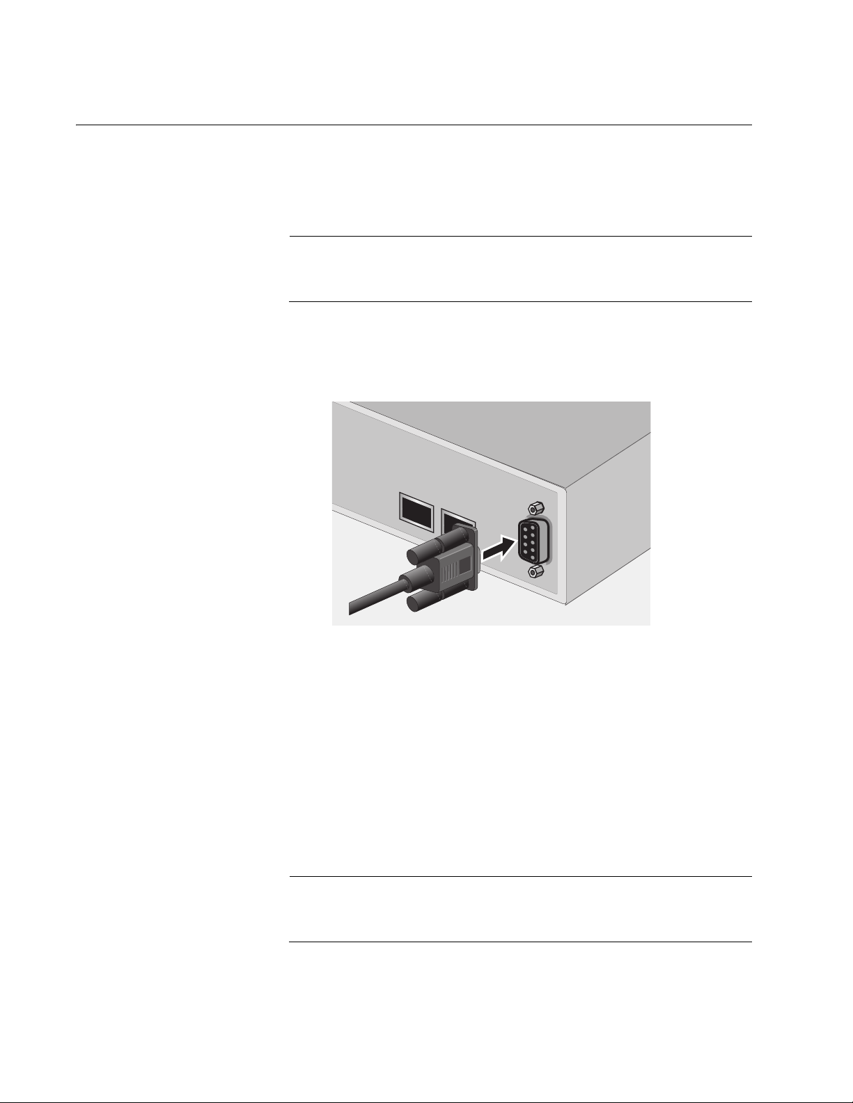
To start a local management session, perform the following procedure:
1. Connect one end of the management cable included with the switch to
the Console port on the switch, as shown in Figure 1.
23
24
CONSOLE
Figure 1. Connecting the Management Cable to the Console Port
2. Connect the other end of the cable to the RS-232 port on a terminal or
PC with a terminal emulator program.
3. Configure the terminal or terminal emulator program as follows:
Baud per second: 9600
Data bits: 8
Stop bits: 1
Flow control: None
Note
These settings are for a DEC VT100 or ANSI terminal, or an
equivalent terminal emulation program. They cannot be changed.
26 Section I: Using the Menus Interface
Page 27

AT-S80 Management Software User’s Guide
The Login Menu is shown in Figure 2.
======================================================
AT-FS750/16 Management System
Local - Console
Allied Telesis International Corp.
Copyright 2008
======================================================
Login Menu
Login:
Figure 2. Login Menu
4. Enter the manager login name and press Return. The default name is
“manager.”
You are prompted for a password.
5. Enter the manager password. The default password is “friend.”
Note
The login name and password are case sensitive. To change the
login name or password, refer to “Setting the User Interface
Configuration” on page 38.
The Main Menu is shown in Figure 3.
Main Menu
[G]eneral Information
[B]asic Switch Configuration
[A]dvanced Switch Configuration
Switch [T]ools
[S]tatistics
[Q]uit
Command>
Figure 3. Main Menu
Section I: Using the Menus Interface 27
Page 28

Chapter 2: Getting Started with the Menus Interface
Using the Menus Interface
If you are using a DEC VT00 or ANSI (the default) terminal configuration,
refer to Table 1 for instructions on how to move through the menus and
select menu options.
When directed to You must
Enter your selection Type the menu option letter.
Table 1. Menus Interface Operations
Enter information (for
example, entering a port
number)
Return to previous menu Type Q for Quit to Previous Menu.
When you press Enter to select a field in which you can enter a value, the
“>” symbol is displayed. For example:
Enter new password>
The “>” symbol indicates that you can enter a new value for the parameter
or change the existing value. After you have entered a value, press Enter.
Changes are immediately activated on the switch.
Type the information and press Enter.
28 Section I: Using the Menus Interface
Page 29

Quitting from a Local Management Session
To quit from a local management session, return to the Main Menu and
type Q for Quit. Always be sure to exit from a management session when
you are finished. This can protect the switch from unauthorized changes to
its configuration should you leave your workstation unattended.
Note
A local management session automatically times out if there is no
management activity during a timeout period. The timeout feature is
intended to protect the parameter settings on the switch from
unauthorized changes should you leave your management station
unattended during a management session. The default timeout
value is 10 minutes. To change the timeout default value, refer to
“Setting the User Interface Configuration” on page 38.
AT-S80 Management Software User’s Guide
Section I: Using the Menus Interface 29
Page 30

Chapter 2: Getting Started with the Menus Interface
30 Section I: Using the Menus Interface
Page 31

Chapter 3
Basic Switch Parameters
This chapter contains the following sections:
“Configuring the IP Address, Subnet Mask, and Gateway Address” on
page 32
“Enabling and Disabling the DHCP Client” on page 35
“Configuring System Administration Information” on page 36
“Setting the User Interface Configuration” on page 38
“Viewing Switch Information” on page 43
“Rebooting the Switch” on page 46
“Pinging a Remote System” on page 48
“Returning the AT-S80 Management Software to the Factory Default
Values” on page 51
Section I: Using the Menus Interface 31
Page 32

Chapter 3: Basic Switch Parameters
Configuring the IP Address, Subnet Mask, and Gateway Address
This procedure explains how to manually assign an IP address, subnet
mask, and gateway address to the switch. Note the following before
performing the procedure:
The switch does not need an IP address, subnet mask, or default
gateway for normal network operations. These parameters must be
assigned values only if you plan to remotely manage the device with a
web browser from a management workstation on your network.
A gateway address is only required if your remote management station
is separated from the switch by a router.
To configure the switch to obtain its IP configuration from a DHCP
server on the network, go to “Enabling and Disabling the DHCP Client”
on page 35.
To manually configure the switch’s IP settings, perform the following
procedure:
1. From the Main Menu, type B to select Basic Switch Configuration.
The Basic Switch Configuration Menu is shown in Figure 4.
Main Menu -> Basic Switch Configuration Menu
System [A]dministration Configuration
System [I]P Configuration
S[N]MP Configuration
[P]ort Configuration
[U]ser Interface Configuration
Rapid [S]panning Tree Configuration
[B]andwidth Control Configuration
IP Access [L]ist
Destination MAC [F]ilter
[Q]uit to previous menu
Command>
Figure 4. Basic Switch Configuration Menu
32 Section I: Using the Menus Interface
Page 33

AT-S80 Management Software User’s Guide
2. From the Basic Switch Configuration Menu, type I to select System IP
Configuration.
The System IP Configuration Menu is shown in Figure 5.
Basic Switch Configuration -> System IP Configuration Menu
MAC Address: 00:06:5H:B2:65:84
IP Address: 0.0.0.0
Subnet Mask: 0.0.0.0
Default Gateway: 0.0.0.0
DHCP Mode: Disabled
----------------------- <COMMAND> ----------------------------Set [I]P Address
Set Subnet [M]ask
Set Default [G]ateway
Enable/Disable [D]HCP Mode
[Q]uit to previous menu
Command>
3. To set the switch’s IP address, do the following:
4. To set the switch’s subnet mask, do the following:
Figure 5. System IP Configuration Menu
The top portion of the menu displays the current IP address, subnet
mask, and gateway address for the switch. The menu displays the
switch’s MAC address, which cannot be changed. The menu also
displays the current status of the DHCP client on the switch.
The Enable/Disable DHCP Mode option is described in “Enabling and
Disabling the DHCP Client” on page 35.
a. Type I to select Set IP Address.
The following prompt is displayed:
Enter new IP address>
b. Type the IP address for the switch and press Enter.
a. Type M to select Set Subnet Mask.
The following prompt is displayed:
Enter new subnet mask>
Section I: Using the Menus Interface 33
Page 34

Chapter 3: Basic Switch Parameters
b. Type the subnet mask for the switch and press Enter.
5. To set the switch’s gateway address, do the following:
a. Type G to select Set Default Gateway.
The following prompt is displayed:
Enter new gateway IP address>
b. Type the gateway IP address for the switch and press Enter.
6. Type Q to select Quit to previous menu and save your changes.
34 Section I: Using the Menus Interface
Page 35

Enabling and Disabling the DHCP Client
This procedure explains how to activate and deactivate the DHCP client
on the switch. When the client is activated, the switch obtains its IP
configuration from a DHCP server on your network. Note the following
before performing the procedure:
The switch does not need an IP address, subnet mask, or default
gateway for normal network operations. These parameters must be
assigned values only if you plan to remotely manage the device with a
web browser from a management workstation on your network.
A gateway address is only required if your remote management station
is separated from the switch by a router.
The default setting for the DHCP client is disabled.
The DHCP client does not support BOOTP servers.
To activate or deactivate the DHCP client, perform the following
procedure:
AT-S80 Management Software User’s Guide
1. From the Main Menu, type B to select Basic Switch Configuration.
The Basic Switch Configuration Menu is shown in Figure 4 on page 32.
2. From the Basic Switch Configuration Menu, type I to select System IP
Configuration.
The System IP Configuration Menu is shown in Figure 5 on page 33.
3. Type D to select Enable/Disable DHCP Mode.
The following prompt is displayed:
Enable or Disable DHCP mode (E/D)>
4. Type E to select Enable or D to select Disable.
If activated, the client immediately begins to send queries to the DHCP
server. It continues to send queries until it receives a response.
5. Type Q to select Quit to previous menu and save your changes.
Section I: Using the Menus Interface 35
Page 36

Chapter 3: Basic Switch Parameters
Configuring System Administration Information
This section explains how to assign a name to the switch. It also explains
how to specify the location of the switch and the name of the switch’s
administrator. Entering this information is optional.
To set a switch’s administration information, perform the following
procedure:
1. From the Main Menu, type B to select Basic Switch Configuration.
The Basic Switch Configuration Menu is shown in Figure 4 on page 32.
2. From the Basic Switch Configuration Menu, type A to select System
Administration Information.
The System Administration Configuration Menu is shown in Figure 6.
Basic Switch Configuration -> System Admin. Configuration Menu
Description: AT-FS750/16
Object ID:
Name:
Location:
Contact:
----------------------- <COMMAND> ----------------------------Set System [N]ame
Set System [L]ocation
Set System [C]ontact Information
[Q]uit to previous menu
Command>
Figure 6. System Administration Configuration Menu
The Description parameter displays the model name of the switch. It
cannot be changed.
3. To set the system’s name, do the following:
a. Type N to select Set System Name.
The following prompt is displayed:
Enter system name>
36 Section I: Using the Menus Interface
Page 37

AT-S80 Management Software User’s Guide
b. Type a name for the switch (for example, Sales). The name is
optional and can contain up to 50 characters.
Note
Allied Telesis recommends assigning a name to each switch.
Names can make it easier for you to identify the various switches in
your network and can also help you avoid performing a configuration
procedure on the wrong switch.
Note
The Object ID field indicates the SNMP product ID or this switch. It is
in the MIB object format. You cannot alter this field.
4. To enter the system’s location, do the following:
a. Type L to select Set System Location.
The following prompt is displayed:
Enter system location>
b. Type information to describe the location of the switch (for
instance, Third Floor). The location is optional and can contain up
to 50 characters.
5. To enter the administrator’s name, do the following:
a. Type C to select Set System Contact Information.
The following prompt is displayed:
Enter system contact>
b. Type the name of the network administrator responsible for
managing the switch. The contact name is optional and can
contain up to 50 characters.
6. Type Q to select Quit to previous menu and save your changes.
Section I: Using the Menus Interface 37
Page 38

Chapter 3: Basic Switch Parameters
Setting the User Interface Configuration
This procedure explains how to adjust the user interface and security
features on the switch. With this procedure you can:
Change the console timer, used to automatically end inactive local
management sessions.
Change the AT-S80 management login user name and password.
Enable and disable the web server, used to manage the switch from a
remote management station with a web browser.
For information about how to configure a dial-in user, see Chapter 9, “Dialin User Configuration” on page 95.
To set the switch’s user interface configuration, perform the following
procedure:
1. From the Main Menu, type B to select Basic Switch Configuration.
The Basic Switch Configuration Menu is shown in Figure 4 on page 32.
2. From the Basic Switch Configuration Menu, type U to select User
Interface Configuration.
38 Section I: Using the Menus Interface
Page 39

AT-S80 Management Software User’s Guide
The User Interface Configuration Menu is shown in Figure 7.
Basic Switch Configuration -> User Interface Configuration Menu
Console UI Idle Timeout: 5 Min.
Password Protection: Enabled
SNMP Agent: Enabled
Web Server: Enabled
Administrator List:
No. Username Password No. Username Password
-- -------- -------- -- ------- -------1 manager ****** 2
34
56
78
----------------------- <COMMAND> -----------------------------
Set [C]onsole UI Time Out Enable/Disable [W]eb Server
Enable/Disable [S]NMP Agent [R]ADIUS Server Configuration
[A]dd Administrator [D]elete Administrator
[M]odify Administrator Enable/Disable Password Pr[o]tection
[Q]uit to previous menu
Command>
Figure 7. User Interface Configuration Menu
The RADIUS Server Configuration option is described Chapter 18,
“RADIUS Authentication Protocol” on page 207.
3. To configure the console idle time out parameter, do the following:
a. Type C to select Set Console UI Time Out.
The following prompt is displayed:
Enter console idle timeout>
b. Enter a number for the timeout value. The range is 0 to 60 minutes.
The default is 5 minutes. A timeout value of 0 causes the switch to
never timeout a local management session.
The console idle time out parameter specifies the length of time a
local management session can be inactive before the management
software automatically ends it. The purpose of this parameter is to
prevent unauthorized individuals from configuring the switch
should you leave your management workstation unattended.
Section I: Using the Menus Interface 39
Page 40

Chapter 3: Basic Switch Parameters
This parameter applies to a local management session but not to a
remote web management session. A web browser management
session remains active so long as your web browser is open.
Note
If you select 0, you must always remember to properly log off from a
local management session when you are finished to prevent
blocking future management sessions with the switch.
4. To enable or disable the web server, do the following:
a. Type W to select Enable/Disable Web Server.
The following prompt is displayed:
Enable or Disable web server (E/D)>
b. Type E to enable the web server or D to disable it. The default is
enabled. If you disable the web server, you can not manage the
switch from a remote management station using a web browser.
5. To enable or disable an SNMP agent, do the following:
a. Type S to select SNMP Agent.
The following prompt is displayed:
Enable or Disable SNMP agent (E/D)
b. Type E to enable an SNMP agent or D to disable the SNMP agent.
6. To add a new user and password, do the following:
a. Type A to select Add Administrator.
The following prompt is displayed:
Enter entry number>
b. Enter the number of the user name. You can select numbers 2
through 8.
The following prompt is displayed:
Enter new user name>
c. Enter the name of a user.
The following prompt is displayed:
Enter new password>
40 Section I: Using the Menus Interface
Page 41

AT-S80 Management Software User’s Guide
d. Enter a password for the new user. You are prompted to reenter
the password.
The following prompt is displayed:
Retype new password>
e. Retype the password for the new user.
7. To delete a user name, do the following:
a. Type D to select Delete Administrator.
The following prompt is displayed:
Enter entry number>
b. Enter the number of the user name that you want to delete. After
you enter it, the Administrator List is refreshed.
8. To modify a user name, do the following
a. Type M to select Modify Administrator.
The following prompt is displayed:
Enter entry number>
b. Enter the number of the user name. You can select numbers 2
through 8.
The following prompt is displayed:
Choose which to be modified (U/P/B)>
c. Type U to change the user name.
The following prompt is displayed:
Enter new user name>
d. Enter the name of the new user. Type P to change the password.
The following prompt is displayed:
Enter new password>
e. Type the new password and press Enter. The password can be
from 0 to 12 characters. Allied Telesis recommends not using
special characters, such as spaces and exclamation points. The
password is case sensitive. Not entering a new password deletes
the current password without assigning a new one.
Section I: Using the Menus Interface 41
Page 42

Chapter 3: Basic Switch Parameters
The following prompt is displayed:
Retype new password.
f. Enter the new password a second time. You must use the new
login password the next time you start a local or web browser
management session.
g. To change both the user name and its corresponding password,
type B.
The following prompt is displayed:
Enter new user name>
h. Enter the name of the new user.
The following prompt is displayed:
Enter new password>
i. Enter the new password.
The following prompt is displayed:
Retype new password>
j. Reenter the new password.
9. To enable or disable password protection, type O.
The following prompt is displayed:
Enable or Disable password protection (E/D)?>
a. Type E to enable password protection or D to disable password
protection.
You can control login authentication by enabling password
protection which requires a user to supply a password when
logging onto the switch. If you disable password protection, a user
can login without inputting a password.
10.Type Q to select Quit to previous menu and save your
changes.
42 Section I: Using the Menus Interface
Page 43

Viewing Switch Information
To view general information about the switch, perform the following
procedure:
1. From the Main Menu, type G to select General Information.
The General Information menu is shown in Figure 8.
Main Menu -> General Information
System up for: 24min(s), 36sec(s)
Runtime Image: Version AT-S80 V2.0.0 [1.1.1.57]
Boot Loader: Version 1.00.03
Hardware Information
Version: DRAM Size: 16MB
Fixed Baud Rate: 9600bps Flash Size: 4 MB
Administration Information
Switch Name: Marketing
Switch Location: Fourth Floor
Switch Contact: Ralph
System Address Information
MAC Address: 00:06:5H:B2:65:84
IP Address: 149.35.8.237
Subnet Mask: 255.255.255.0
Gateway: 149.35.8.1
Automatic Network Features
DHCP Mode: Disabled
AT-S80 Management Software User’s Guide
Press any key to continue...
Figure 8. General Information Menu
The General Information Menu displays the following information:
System up for
The number of hours, minutes, and seconds since the last reset or
power cycle.
Runtime Image
The version of the runtime software.
Boot Loader
The version of the boot loader software.
Section I: Using the Menus Interface 43
Page 44

Chapter 3: Basic Switch Parameters
Hardware Information Section
Version
The hardware version number.
Fixed Baud Rate
The baud rate of the console port.
DRAM Size
The size of the DRAM, in megabytes.
Flash Size
The size of the flash memory, in megabytes.
Administration Information Section
Switch Name
The name of the switch. To assign a name, refer to “Configuring
System Administration Information” on page 36.
Switch Location
The location of the switch. To specify the location, refer to “Configuring
System Administration Information” on page 36.
Switch Contact
The contact person responsible for managing the switch. To specify a
contact, refer to “Configuring System Administration Information” on
page 36.
System Address Information Section
MAC Address
The MAC address of the switch. You cannot change a switch’s MAC
address.
System IP Address
The switch’s IP address. Refer to “Configuring the IP Address, Subnet
Mask, and Gateway Address” on page 32 to manually assign an IP
address or “Enabling and Disabling the DHCP Client” on page 35 to
activate the DHCP client.
Subnet Mask
The switch’s subnet mask. Refer to “Configuring the IP Address,
Subnet Mask, and Gateway Address” on page 32 to manually assign a
subnet mask or “Enabling and Disabling the DHCP Client” on page 35
to activate the DHCP client.
Gateway
The switch’s default gateway IP address. Refer to “Configuring the IP
Address, Subnet Mask, and Gateway Address” on page 32 to
manually assign a gateway address or “Enabling and Disabling the
DHCP Client” on page 35 to activate the DHCP client.
44 Section I: Using the Menus Interface
Page 45

AT-S80 Management Software User’s Guide
Automatic Network Features Section
DHCP Mode
The status of the DHCP client on the switch. For information about
setting this parameter, refer to “Enabling and Disabling the DHCP
Client” on page 35.
2. Press any key to return to the previous menu.
Section I: Using the Menus Interface 45
Page 46

Chapter 3: Basic Switch Parameters
Rebooting the Switch
This procedure reboots the switch and reloads the AT-S80 management
software from flash memory. You can reboot the device if you believe it is
experiencing a problem. Rebooting the switch does not change any of the
its parameter settings.
To reboot the switch, perform the following procedure:
1. From the Main Menu type T to select Switch Tools.
Caution
The switch does not forward network traffic during the reboot
process. Some network traffic may be lost.
The Switch Tools Configuration Menu is shown in Figure 9.
Main Menu -> Switch Tools Configuration Menu
Software [U]pgrade...
System [R]eboot
[P]ing Execution
[Q]uit to previous menu
Command>
Figure 9. Switch Tools Configuration Menu
2. From the Switch Tools Configuration Menu, type R to select System
Reboot.
46 Section I: Using the Menus Interface
Page 47

AT-S80 Management Software User’s Guide
The System Reboot Menu is shown in Figure 10.
Main Menu -> System Reboot Menu
Reboot Status: Stop
Reboot Type: Normal
---------------------- <COMMAND> ----------------------------
Set Reboot [O]ption
Start [R]eboot Process
[Q]uit to previous menu
Command>
Figure 10. System Reboot Menu
3. From the System Reboot menu, type O to select Set Reboot Option.
The following prompt is displayed:
Select reboot option (F/I/N)>
4. Type N to select Normal.
Note
The F and I options are described in “Returning the AT-S80
Management Software to the Factory Default Values” on page 51.
5. Type R to select Start Reboot Process.
The following prompt is displayed:
Are you sure you want to reboot the system (Y/N)>
6. Type Y to start the reboot process or N to cancel the reboot.
The switch immediately begins to reload the AT-S80 management
software. This process takes approximately one minute to complete.
You can not manage the device during the reboot. You can log in again
after the reboot is finished if you want to continue to manage the
device.
Section I: Using the Menus Interface 47
Page 48

Chapter 3: Basic Switch Parameters
Pinging a Remote System
This procedure instructs the switch to ping a node on your network. This
procedure is useful in determining whether an active link exists between
the switch and another network device. Note the following before
performing the procedure:
The switch must have an IP address and subnet mask.
The device to be pinged by the switch must be a member of the
Default VLAN. It must be communicating with the switch through an
untagged or tagged port of the Default VLAN.
To instruct the switch to ping a network device, perform the following
procedure:
1. From the Main Menu, type T to select Switch Tools.
The Switch Tools Configuration Menu is shown in Figure 9 on page 46.
2. From the Switch Tools Configuration Menu, type P to select Ping
Execution.
The Ping Execution Menu is shown in Figure 11.
Switch Tools Configuration -> Ping Execution
Target IP Address: 0.0.0.0
Number of Requests: 10
Timeout Value (sec): 3
================Result=================
----------------------- <COMMAND> ----------------------------Set Target [I]P Address [E]xecute Ping
Set [N]umber of Requests [S]top Ping
Set [T]imeout Value [Q]uit to previous menu
Command>
Figure 11. Ping Execution Menu
48 Section I: Using the Menus Interface
Page 49

AT-S80 Management Software User’s Guide
3. Type I to select Set Target IP Address.
The following prompt is displayed:
Enter new target IP address>
4. Type the IP address of the node the switch is to ping and press Enter.
5. Type N to select Set Number of Requests.
The following prompt is displayed:
Enter new number of requests>
6. Enter the number of ping requests you want the switch to perform. The
range is 1 to 10. The default is 10.
7. Type T to select Set Timeout Value.
The following prompt is displayed:
Enter new timeout value>
8. Enter the length of time in seconds the switch is to wait for a response
before assuming that a ping has failed. The range is 1 to 5 seconds.
The default is 3 seconds.
9. Type E to select Execute Ping.
The following prompt is displayed:
Execute ping or Clean ping data (E/C)>
10. Type E to execute the ping or C to clear previous ping data.
Section I: Using the Menus Interface 49
Page 50

Chapter 3: Basic Switch Parameters
Switch Tools Configuration -> Ping Execution
Target IP Address: 149.35.8.33
Number of Requests: 4
Timeout Value (sec): 3
================Result=================
----------------------- <COMMAND> ----------------------------Set Target [I]P Address [E]xecute Ping
Set [N]umber of Requests [S]top Ping
Set [T]imeout Value [Q]uit to previous menu
Command>
Figure 12 shows an example of the results of a ping.
No. 1 20 ms
No. 2 20 ms
No. 3 20 ms
No. 4 20 ms
Figure 12. Ping Results
11. To stop the ping, type S to select Stop Ping.
12. Type Q to select Quit to previous menu.
50 Section I: Using the Menus Interface
Page 51

AT-S80 Management Software User’s Guide
Returning the AT-S80 Management Software to the Factory Default Values
This procedure returns all AT-S80 Management Software parameters to
their default values. The default values are listed in Appendix A, ”AT-S80
Software Default Settings” on page 339.
Caution
This procedure reboots the switch. The device does not forward
network traffic during the reboot process. Some network traffic may
be lost.
To return the AT-S80 management software to its default settings, perform
the following procedure:
1. From the Main Menu, type T to select Switch Tools.
The Switch Tools Configuration Menu is shown in Figure 9 on page 46.
2. From the Switch Tools Menu, type R to select System Reboot to start
the reboot.
The System Reboot menu is shown in Figure 10 on page 47.
3. Type O to select Set Reboot Option.
The following prompt is displayed:
Select reboot option (F/I/N)>
4. Type F or I to select one of the following:
F (Factory Default)
Resets all switch parameters to the factory default settings, including
IP address, subnet mask, and gateway address. If the DHCP client is
enabled, this selection disables it.
I (Reset to Defaults Except IP Address)
Resets all switch parameters to the factory default settings, but retains
the IP address, subnet mask, and gateway settings. If the DHCP client
is enabled, it remains enabled after this reset.
Note
Option N is described in “Rebooting the Switch” on page 46.
Section I: Using the Menus Interface 51
Page 52

Chapter 3: Basic Switch Parameters
5. Type R to select Start Reboot Process.
The following prompt is displayed:
Are you sure you want to reboot the system (Y/N)>
6. Type Y to start the reboot process.
The switch returns its operating parameters to the default values and
begins to reload the AT-S80 Management Software. This process
takes approximately one minute to complete. You can not manage the
device during the reboot. After the reboot is finished, you can log in
again if you want to continue to manage the device.
52 Section I: Using the Menus Interface
Page 53

Chapter 4
Port Configuration
This chapter contains the procedures for viewing and adjusting the
parameter settings for the ports on the switch. This chapter contains the
following sections:
“Displaying the Port Parameters” on page 54
“Enabling and Disabling a Port” on page 56
“Setting a Port’s Speed and Duplex Mode” on page 57
“Changing the Flow Control Setting” on page 59
Section I: Using the Menus Interface 53
Page 54

Chapter 4: Port Configuration
Displaying the Port Parameters
To display the parameter settings for the ports on the switch, perform the
following procedure:
1. From the Main Menu, type B to select Basic Switch Configuration.
The Basic Switch Configuration Menu is shown in Figure 4 on page 32.
2. From the Basic Switch Configuration Menu, type P to select Port
Configuration.
The Port Configuration Menu is shown in Figure 13.
Basic Switch Configuration -> Port Configuration Menu
Port Trunk Type Link Status Mode Flow Ctrl
---- ----- ------ ---- ------ --------------------1 --- 10/100TX Up Enabled Auto (100F) Enabled
2 --- 10/100TX Up Enabled Auto (100F) Enabled
3 --- 10/100TX Up Enabled 100-FDx Enabled
4 --- 10/100TX Up Enabled Auto (10F) Enabled
5 --- 10/100TX Up Enabled Auto (100F) Enabled
6 --- 10/100TX Down Enabled Auto Enabled
7 --- 10/100TX Up Enabled Auto (100F) Enabled
8 --- 10/100TX Down Enabled Auto Enabled
9 --- 10/100TX Up Enabled Auto (100F) Enabled
10 --- 10/100TX Up Enabled 10-FDx Enabled
11 --- 10/100TX Up Enabled 10-FDx Enabled
12 --- 10/100TX Up Enabled Auto (100F) Enabled
----------------------- <COMMAND> ------------------------------------
[N]ext Page Set [S]tatus Set [F]low Control
[P]revious Page Set [M]ode [Q]uit to previous menu
Command>
Figure 13. Port Configuration Menu
The Port Configuration Menu displays the following columns of
information:
Port
The port number.
Trunk
The trunk group number. This column contains the number of the port
trunk if the port is a member of a trunk. To configure a trunk, refer to
Chapter 5, “Port Trunking” on page 61.
54 Section I: Using the Menus Interface
Page 55

AT-S80 Management Software User’s Guide
Type
The port type. The port type will be one of the following:
10/100BaseTX - Base ports.
1000TX - Uplink 10/100/1000Base-TX twisted pair ports.
1000BaseX - Optional fiber optic SFP module.
Link
The status of the link between the port and the end node connected to
the port. The possible values are:
Up - A link exists between the port and the end node.
Down - The port has not established a link with an end node.
Status
The current operating status of the port. The possible values are:
Enabled - The port is able to send and receive Ethernet frames. This is
the default setting for all ports on the switch.
Disabled - The port was manually disabled.
To change a port’s status, see “Enabling and Disabling a Port” on
page 56.
Mode
The port’s speed and duplex mode setting. The possible values are:
Auto - The port is using Auto-Negotiation to set its operating speed and
duplex mode. This is the default setting. The actual operating speed
and duplex mode are displayed in parentheses (for example, “Auto
(100F)” for 100 Mbps full duplex mode).
If the speed and duplex mode were set manually on a port, the Mode
column will be one of the following:
10-HDx - 10 Mbps, half-duplex mode
100-HDx - 100 Mbps, half-duplex mode
10-FDx - 10 Mbps, full-duplex mode
100-FDx - 100 Mbps, full-duplex mode
1000-FDx - 1000 Mbps, full-duplex mode (uplink ports only)
To change a port’s speed and duplex mode setting, see “Setting a
Port’s Speed and Duplex Mode” on page 57.
Flow Ctrl
Whether flow control is enabled on the port. Flow control is enabled by
default. To disable flow control, refer to “Changing the Flow Control
Setting” on page 59.
3. Type Q to select Quit to previous menu.
Section I: Using the Menus Interface 55
Page 56

Chapter 4: Port Configuration
Enabling and Disabling a Port
This procedure allows you to enable or disable a port. A disabled port
does not forward any ingress or egress packets. You may want to disable
a port if a problem occurs with the node or cable connected to the port.
After the problem is fixed, you can enable the port to resume normal
operation. You can also disable an unused port to secure it from
unauthorized connections. The default setting for a port is enabled.
To change the port’s status, perform the following procedure:
1. From the Main Menu, type B to select Basic Configuration.
The Basic Switch Configuration Menu is shown in Figure 4 on page 32
2. From the Basic Switch Configuration Menu, type P to select Port
Configuration.
The Port Configuration Menu is shown in Figure 13 on page 54.
3. Type S to select Set Status.
The following prompt is displayed:
Set Status->Enter port number>
4. Enter the number of the port to enable or disable. You can configure
only one port at a time.
The following prompt is displayed:
Enable or Disable port n (E/D)>
5. Type E to enable the port or D to disable it. The default is enabled. A
disabled port immediately stops forwarding all ingress and egress
traffic until you enable it again.
The display is refreshed to show the port’s new status.
6. Type Q to select Quit to previous menu and save your changes.
56 Section I: Using the Menus Interface
Page 57

Setting a Port’s Speed and Duplex Mode
To change a port’s speed or duplex mode, perform the following
procedure:
1. From the Main Menu, type B to select Basic Configuration.
The Basic Switch Configuration Menu is shown in Figure 4 on page 32
2. From the Basic Switch Configuration Menu, type P to select Port
Configuration.
The Port Configuration Menu is shown in Figure 13 on page 54.
3. Type M to select Set Mode.
The following prompt is displayed:
Set Mode -> Enter port number >
AT-S80 Management Software User’s Guide
4. Enter the number of the port whose speed or duplex mode you want to
change. You can configure only one port at a time.
The following prompt is displayed:
Enter new mode for port n (a/h/H/f/F/T)>
5. Enter the letter that corresponds to the desired speed and duplex
mode setting for the port. The port settings are:
a - Auto: The port uses Auto-Negotiation to set its speed and duplex
mode. This is the default setting for all ports.
h - 10 Mbps, half-duplex
f - 10 Mbps, full-duplex
H - 100 Mbps, half-duplex
F - 100 Mbps, full-duplex
T - 1000 Mbps, full-duplex (uplink ports only)
When selecting a setting, note the following:
The selections are case sensitive. For example, you must enter a
lowercase letter “a” to select Auto-Negotiation.
When a twisted pair port on the switch is set to Auto-Negotiation,
the default setting, the end node should also be set to AutoNegotiation to prevent a duplex mode mismatch. A switch port
using Auto-Negotiation defaults to half-duplex if it detects that the
end node is not using Auto-Negotiation. This can result in a
Section I: Using the Menus Interface 57
Page 58

Chapter 4: Port Configuration
mismatch if the end node is operating at a fixed duplex mode of
full-duplex. To avoid this problem, disable Auto-Negotiation on the
port and set the port’s speed and duplex mode manually when
connecting an end node with a fixed duplex mode of full-duplex to
a switch port.
For 1000 Mbps operation on an uplink 10/100/1000Base-T twisted
pair uplink port, Allied Telesis recommends using AutoNegotiation. Setting the speed and duplex mode manually to 1000
Mbps full duplex is not recommended.
The only valid setting for an optional SFP port is Auto-Negotiation.
6. Type Q to select Quit to previous menu and save your changes.
58 Section I: Using the Menus Interface
Page 59

Changing the Flow Control Setting
Flow control applies to ports operating in full-duplex mode. A switch port
uses flow control to control the flow of ingress packets from its end node. A
port using flow control issues a special frame, referred to as a PAUSE
frame, as specified in the IEEE 802.3x standard, to stop the transmission
of data from an end node. When a port needs to stop an end node from
transmitting data, it issues this frame. The frame instructs the end node to
cease transmission. The port continues to issue PAUSE frames until it is
ready again to receive data from the end node.
To change the flow control setting on a port, perform the following
procedure:
1. From the Main Menu, type B to select Basic Configuration.
The Basic Switch Configuration Menu is shown in Figure 4 on page 32
2. From the Basic Switch Configuration Menu, type P to select Port
Configuration.
AT-S80 Management Software User’s Guide
The Port Configuration Menu is shown in Figure 13 on page 54.
3. Type F to select Set Flow Control.
The following prompt is displayed:
Set Flow Control -> Enter port number >
4. Type the port number whose flow control setting you want to change.
Then press Enter. You can configure only one port at a time.
The following prompt is displayed:
Enable or Disable flow control for port <n> (E/D)>
5. Type E to enable flow control or D to disable it. The default is enabled.
The display is refreshed to show the port’s new flow control setting.
6. Type Q to select Quit to previous menu and save your changes.
Section I: Using the Menus Interface 59
Page 60

Chapter 4: Port Configuration
60 Section I: Using the Menus Interface
Page 61

Chapter 5
Port Trunking
This chapter provides information and procedures for creating a port trunk
and contains the following sections:
“Port Trunking Overview” on page 62
“Creating a Port Trunk” on page 64
“Modifying a Port Trunk” on page 67
“Enabling and Disabling a Port Trunk” on page 69
Section I: Using the Menus Interface 61
Page 62

Chapter 5: Port Trunking
Port Trunking Overview
Port trunking is an economical way for you to increase the bandwidth
between two Ethernet switches. A port trunk is 2 to 8 ports that have been
grouped together to function as one logical path. A port trunk increases
the bandwidth between switches and is useful in situations where a single
physical data link between switches is insufficient to handle the traffic
load.
A port trunk always sends packets from a particular source to a particular
destination over the same link within the trunk. A single link is designated
for flooding broadcasts and packets of unknown destination.
Port Trunking
Guidelines
Observe the following guidelines when creating a port trunk:
A port trunk can consist of up to 8 ports.
The switch can support up to 7 trunks.
A port can belong to only one trunk at a time.
The ports of a trunk must be of the same medium type. For example,
they can be all twisted pair ports or all fiber optic ports.
The speed, duplex mode, and flow control settings must be the same
on all the ports in a trunk.
The ports of a trunk must be members of the same VLAN.
The ports of a trunk do not have to be consecutive.
When you cable a trunk, the order of the connection should be
maintained on both nodes. The lowest numbered port in a trunk on the
switch should be connected to the lowest numbered port of the trunk
on the other device, the next lowest numbered port on the switch
should be connected to the next lowest numbered port on the other
device, and so on.
For example, assume that you are connecting a trunk between two
AT-FS750 switches. On the first AT-FS750 switch, select ports 1
through 4 for a trunk. On the second AT-FS750 switch, select ports 6
through 9. To maintain the order of the port connections, connect port
1 on the first AT-FS750 switch to port 6 on the second AT-FS750
switch, port 2 to port 7, and so on.
To avoid compatibility problems, Allied Telesis recommends that both
switches connected by a trunk are AT-FS750 switches. A port trunk
between an AT-FS750 switch and another switch model might result in
undesirable trunk behavior.
62 Section I: Using the Menus Interface
Page 63

AT-S80 Management Software User’s Guide
Trunk 7 is reserved for the uplink ports 17 and 18 on the AT-FS750/16
switch and ports 25 and 26 on the AT-FS750/24 switch. You cannot
add or remove ports from this trunk. To use the uplink ports as a port
trunk, activate Trunk 7 as explained in “Enabling and Disabling a Port
Trunk” on page 69.
Section I: Using the Menus Interface 63
Page 64

Chapter 5: Port Trunking
Creating a Port Trunk
This procedure explains how to create a port trunk.
To create a port trunk, perform the following procedure:
1. From the Main Menu, type A to select Advanced Switch
Configuration.
The Advanced Switch Configuration Menu is shown in Figure 14.
Caution
Do not connect the cables to the ports on the switches until after you
have configured the trunk with the management software.
Connecting the cables before configuring the software can create a
loop in the network topology. A loop can cause a broadcast storm
and poor network performance.
Main Menu -> Advanced Switch Configuration Menu
[V]LAN Management
[T]runk Configuration
[I]GMP Snooping Configuration
Static Multicast [A]ddress Configuration
Quality of [S]ervice Configuration
Port [M]irroring Configuration
[D]ial-in User Configuration
802.1[X] Port Based Access Control Configuration
[Q]uit to previous menu
Command>
Figure 14. Advanced Switch Configuration Menu
2. From the Advanced Switch Configuration Menu, type T to select
Trunk Configuration.
64 Section I: Using the Menus Interface
Page 65

AT-S80 Management Software User’s Guide
The Trunk Configuration Menu is shown in Figure 15.
AT-FS750/24 Local Management System
Advanced Switch Configuration -> Trunk Configuration Menu
Group Status Port Members Trunk ID
------- -------------- --------------------- ---------1 Disabled 1
2 Disabled 2
3 Disabled 3
4 Disabled 4
5 Disabled 5
6 Disabled 6
7 Disabled 25, 26 7
----------------------- <COMMAND> -----------------------------
[A]dd Trunk Member [S]et Trunk Status
[R]emove Trunk Member [Q]uit to previous menu
Command>
Figure 15. Trunk Configuration Menu
3. From the Trunk Configuration Menu, type A to select Add Trunk
Member.
The following prompt is displayed:
Enter trunk group number>
4. Select a trunk group number from 1 to 7 and press Enter.
The following prompt is displayed:
Enter port members (up to 8 ports) for trunk n>
5. Enter the ports you want to include in the trunk and press Enter.
You can specify the ports individually separated by commas (for
example, 1,2,5), as a range of ports separated by a hyphen (for
example, 2-4), or both (for example, 4,6,11-14).
6. Type S to select Set Trunk Status.
The following prompt is displayed:
Enter trunk group number>
7. Type the trunk group number and press Enter.
Section I: Using the Menus Interface 65
Page 66

Chapter 5: Port Trunking
The following prompt is displayed:
Enable or Disable trunk group number n (E/D)>
8. Type E to enable the trunk.
9. Type Q to select Quit to previous menu and save your changes.
The trunk is now operational on the switch.
10. Configure the port trunk on the other switch and connect the cables.
66 Section I: Using the Menus Interface
Page 67

Modifying a Port Trunk
This procedure adds and removes ports from a port trunk.
Caution
Disconnect the cables from the ports of the trunk before you modify
the trunk. Leaving the cables connected can create a loop in the
network topology. A loop can cause a broadcast storm and poor
network performance.
Note
You cannot modify Trunk 7, which is reserved for the uplink ports. If
you want to use the uplink ports as a port trunk, activate Trunk 7 as
explained in “Enabling and Disabling a Port Trunk” on page 69.
To add or remove ports from a trunk, perform the following procedure:
AT-S80 Management Software User’s Guide
1. From the Main Menu, type A to select Advanced Switch
Configuration.
The Advanced Switch Configuration Menu is shown in Figure 14 on
page 64.
2. From the Advanced Switch Configuration Menu, type T to select Trunk
Configuration.
The Trunk Configuration Menu is shown in Figure 15 on page 65.
3. To add ports to a port trunk, type A to select Add Trunk Member. To
remove ports, type R to select Remove Trunk Member.
The following prompt is displayed:
Enter trunk group number>
4. Type the number of the trunk group you want to modify and press
Enter.
The following prompt is displayed where n represents the port trunk
number:
Enter port members (from 1 to 24, up to 8 ports) for
trunk
n
>
5. Type the ports you want to add or remove from the trunk. Then press
Enter.
Section I: Using the Menus Interface 67
Page 68

Chapter 5: Port Trunking
You can specify the ports individually separated by commas (for
example, 1,2,5), as a range of ports separated by a hyphen (for
example, 2-4), or both (for example, 4,6,11-14).
6. Type Q to select Quit to previous menu and save your changes.
7. Modify the port trunk on the other switch and reconnect the cables.
68 Section I: Using the Menus Interface
Page 69

Enabling and Disabling a Port Trunk
This procedure enables and disables a port trunk. Note the following
before performing this procedure:
Do not enable a port trunk until after you have configured the trunk on
both switches.
Do not connect the cables to the ports on the switches until after you
have configured and enabled the trunk on both switches.
The ports of a disabled trunk forward traffic as individual ports.
Note
Before disabling a port trunk, disconnect all cables from the ports of
the trunk. Leaving the cables connected can create a loop in your
network topology. A loop can cause a broadcast storm and poor
network performance.
AT-S80 Management Software User’s Guide
To enable or disable a port trunk, perform the following procedure:
1. From the Main Menu, type A to select Advanced Switch
Configuration.
The Advanced Switch Configuration Menu is shown in Figure 14 on
page 64.
2. From the Advanced Switch Configuration Menu, type T to select Trunk
Configuration.
The Trunk Configuration Menu is shown in Figure 15 on page 65.
3. From the Trunk Configuration Menu, type S to select Set Trunk
Status.
The following prompt is displayed:
Enter trunk group number>
Note
Port members must be in the same VLAN or you will receive an error
message and the ports will not be added to a trunk.
4. Type the number of the trunk group you want to enable or disable and
press Enter.
The following prompt is displayed:
Enable or Disable trunk group number n (E/D)>
Section I: Using the Menus Interface 69
Page 70

Chapter 5: Port Trunking
5. Type E to enable the trunk or D to disable it.
6. Type Q to select Quit to previous menu and save your changes.
70 Section I: Using the Menus Interface
Page 71

Chapter 6
IGMP Snooping
This chapter explains how to activate and configure the Internet Group
Management Protocol (IGMP) snooping feature on the switch. Sections in
the chapter include:
“IGMP Snooping Overview” on page 72
“Configuring IGMP Snooping” on page 74
Section I: Using the Menus Interface 71
Page 72

Chapter 6: IGMP Snooping
IGMP Snooping Overview
IGMP enables IPv4 routers to create lists of nodes that are members of
multicast groups. (A multicast group is a group of end nodes that want to
receive multicast packets from a multicast application.) The router creates
a multicast membership list by periodically sending out queries to the local
area networks connected to its ports.
A node that wants to become a member of a multicast group responds to a
query by sending a report. A report indicates an end node’s desire to
become a member of a multicast group. Nodes that join a multicast group
are referred to as host nodes. After becoming a member of a multicast
group, a host node must continue to periodically issue reports to remain a
member.
After the router has received a report from a host node, it notes the
multicast group that the host node wants to join and the port on the router
where the node is located. Any multicast packets belonging to that
multicast group are then forwarded by the router out the port. If a particular
port on the router has no nodes that want to be members of multicast
groups, the router does not send multicast packets out the port. This
improves network performance by restricting multicast packets only to
router ports where host nodes are located.
There are three versions of IGMP — versions 1, 2, and 3. One of the
differences between the versions is how a host node signals that it no
longer wants to be a member of a multicast group. In version 1, it stops
sending reports. If a router does not receive a report from a host node
after a predefined length of time, referred to as a time-out value, it
assumes that the host node no longer wants to receive multicast frames,
and removes it from the membership list of the multicast group.
In version 2, a host node exits from a multicast group by sending a leave
request. After receiving a leave request from a host node, the router
removes the node from appropriate membership list. The router also stops
sending multicast packets from the port to which the node is connected if it
determines there are no further host nodes on the port.
Version 3 adds the ability of host nodes to join or leave specific sources in
a multicast group.
The IGMP snooping feature supports IGMP versions 1 and 2. The ATFS750 switches monitor the flow of queries from a router as well as report
leave messages from host nodes to build its own multicast membership
lists. Both switches use the lists to forward multicast packets to switch
ports where there are host nodes who are members of multicast groups.
This improves switch performance and network security by restricting the
flow of multicast packets only to those switch ports connected to host
nodes.
72 Section I: Using the Menus Interface
Page 73

AT-S80 Management Software User’s Guide
Without IGMP snooping, a switch needs to flood multicast packets from all
of its ports, except the port on which it received the packet. Such flooding
of packets can negatively impact network performance.
The AT-FS750 switches maintain a list of multicast groups through an
adjustable timeout value, which controls how frequently it expects to see
reports from end nodes that want to remain members of multicast groups,
and by processing leave requests.
Note
By default, IGMP snooping is disabled on the switch.
Section I: Using the Menus Interface 73
Page 74

Chapter 6: IGMP Snooping
Configuring IGMP Snooping
The procedures in this section describe how to enable or disable IGMP
snooping, set the age-out timer, and view group members. See the
following procedures:
“Enabling or Disabling IGMP Snooping” on page 74
“Setting the Age-out Timer” on page 76
“Setting Group Members” on page 76
Enabling or
Disabling IGMP
Snooping
Main Menu -> Advanced Switch Configuration Menu
[V]LAN Management
[T]runk Configuration
[I]GMP Snooping Configuration
Static Multicast [A]ddress Configuration
Quality of [S]ervice Configuration
Port [M]irroring Configuration
[D]ial-in User Configuration
802.1[X] Port Based Access Control Configuration
[Q]uit to previous menu
Command>
To activate or deactivate IGMP snooping on the switch, perform the
following procedure:
1. From the Main Menu, type A to select Advanced Switch
Configuration.
The Advanced Switch Configuration Menu is shown in Figure 16.
Figure 16. Advanced Switch Configuration Menu
2. From the Advanced Switch Configuration Menu, type I to select IGMP
Snooping Configuration.
74 Section I: Using the Menus Interface
Page 75

AT-S80 Management Software User’s Guide
The IGMP Snooping Configuration Menu is shown in Figure 17.
Advanced Switch Configuration -> IGMP Snooping Configuration Menu
IGMP Snooping Status: Disabled
IGMP Snooping Age-Out Timer: 280 seconds
Multicast Group Address
-----------------------
-------------------------------<COMMAND>-----------------------------[N}ext Page [E]nable/Disable IGMP Snooping
[P]revious Page [S]et Age-Out Timer
[V]iew Group Members [Q]uit to previous menu
Command>
Figure 17. IGMP Snooping Configuration Menu
3. From the SNMP Configuration Menu, type E to select Enable/Disable
IGMP Configuration.
The following prompt is displayed:
Enable or Disable IGMP snooping (E/D) >
4. Type E to enable IGMP snooping or D to disable IGMP snooping.
By default, IGMP snooping is disabled.
5. Type Q to select Quit to previous menu and save your changes.
Section I: Using the Menus Interface 75
Page 76

Chapter 6: IGMP Snooping
Setting the Age-
out Timer
Use the following procedure to set the age-out timer.
1. From the Main Menu, type A to select Advanced Switch
Configuration.
The Advanced Switch Configuration Menu is shown in Figure 16 on
page 74.
2. From the Advanced Switch Configuration Menu, type I to select IGMP
Snooping Configuration.
The IGMP Configuration Menu is shown in Figure 17 on page 75.
3. From the SNMP Configuration Menu, type S to select Set Age-Out
Timer.
The following prompt is displayed:
Enter age-out time>
For an IGMP member port, the Set Age-Out Timer is set to 280
seconds by default. The range of this parameter is from 280 to
420 seconds.
For an IGMP router port, the Set Age-Out Timer is set to 130 seconds
by default. This value cannot be changed.
Setting Group
Members
4. Type the number of seconds that you want the switch to wait before it
purges an inactive dynamic MAC address which is called the aging
time. Enter a value between 280 and 420 seconds.
5. Type Q to select Quit to previous menu and save your changes.
To set the MAC addresses of IGMP group members, perform the following
procedure:
1. From the Main Menu, type A to select Advanced Switch
Configuration.
The Advanced Switch Configuration Menu is shown in Figure 16 on
page 74.
2. From the Advanced Switch Configuration Menu, type I to select IGMP
Configuration.
The IGMP Configuration Menu is shown in Figure 17 on page 75.
3. From the IGMP Configuration Menu, type V to select View Group
Members.
76 Section I: Using the Menus Interface
Page 77

AT-S80 Management Software User’s Guide
The following prompt is displayed:
Enter MAC Address (xx:xx:xx:xx:xx:xx)>
4. Enter a Multicast Group MAC address in the format xx:xx:xx:xx:xx.
The range of the multicast MAC address is from 01:00:5E:00:01:00 to
01:00:5E:7F:FF:FF.
The IGMP Configuration Menu is updated with the information.
5. Type Q to select Quit to previous menu and save your changes.
Section I: Using the Menus Interface 77
Page 78

Chapter 6: IGMP Snooping
78 Section I: Using the Menus Interface
Page 79

Chapter 7
Static Multicast Address
This chapter explains how to assign static multicast addresses. Sections in
the chapter include:
“Static Multicast Address Overview” on page 80
“Creating a Static Multicast Address” on page 81
Section I: Using the Menus Interface 79
Page 80

Chapter 7: Static Multicast Address
Static Multicast Address Overview
There are 4 ways to populate the database of a MAC address table:
Static unicast addresses which can only be assigned to one port
Static multicast addresses which can be assigned to multiple ports
Broadcast addresses which are broadcast to all of the ports on a
switch
Dynamically learned MAC addresses
If you want the MAC address table to act as a forwarding database,
configure it with static multicast MAC addresses.
The Static Multicast Address feature allows you to assign an IP address to
more than one host. This feature is used for video streaming when you
also enable IGMP snooping. For more information about configuring IGMP
snooping, see Chapter 6, “IGMP Snooping” on page 71.
For the static multicast address, the MAC addresses are prelearned. This
means that you can assign a MAC address before you create a physical
connection to a host.
80 Section I: Using the Menus Interface
Page 81

Creating a Static Multicast Address
The procedures in this section describe how to create, delete, and modify
static multicast addresses. See the following procedures:
“Adding a Static Multicast Address” on page 81
“Deleting a Static Group” on page 82
“Deleting a Static Member Port” on page 83
AT-S80 Management Software User’s Guide
Adding a Static
Multicast
Address
To assign a static multicast address or to assign a group number to an
existing group MAC address, perform the following procedure:
1. From the Main Menu, type A to select Advanced Switch
Configuration.
The Advanced Switch Configuration Menu is shown in Figure 14 on
page 64.
2. From the Advanced Switch Configuration Menu, type A to select Static
Multicast Address Configuration.
The Static Multicast Address Table Menu is shown in Figure 18.
Advanced Switch Configuration -> Static Multicast Address Table Menu
Group MAC Address Group Members
----------------- -------------------------------------------01:00:5E:00:01:00 1
01:00:5E:00:01:01 2
01:00:5E:00:01:02 3, 4,5,6
01:00:5E:00:01:03 7, 8, 9, 10, 11, 12, 13, 14, 15, 16, 17, 18
01:00:5E:00:01:04 19, 20
01:00:5E:00:01:05 21
01:00:5E:00:01:06 22
-------------------------------<COMMAND>-----------------------------[N}ext Page [A]dd Static Member Port Delete Static [G]roup
[P]revious Page [D]elete Static Member Port [Q]uit to previous menu
Command>
Figure 18. Static Multicast Address Table Menu
3. Type A to select Add Static Member Port.
Section I: Using the Menus Interface 81
Page 82

Chapter 7: Static Multicast Address
The following prompt is displayed:
Enter MAC address for multicast entry >
4. Type a multicast MAC address. Then press enter. The range of
acceptable multicast MAC addresses is from 01:00:5E:00:01:00 to
01:00:5E:7F:FF:FF.
The following prompt is displayed:
Select group member >
5. Enter a group member in the range of 1 to 24.
You can add more than one group member at a time. You can specify
the values individually (for example, 2,5,11), as a range (for example,
4-7), or both (for example, 2,5,11-15).
6. Type Q to select Quit to previous menu and save your changes.
Deleting a Static
Group
To delete a group from a Group MAC address, perform the following
procedure.
1. From the Main Menu, type A to select Advanced Switch
Configuration.
The Advanced Switch Configuration Menu is shown in Figure 14 on
page 64.
2. From the Advanced Switch Configuration Menu, type A to select
Static Multicast Address Configuration.
The Static Multicast Address Table Menu is shown in Figure 18 on
page 81.
3. Type G to select Delete Static Group.
The following prompt is displayed:
Enter MAC address for multicast entry >
4. Type a multicast MAC address. Then press enter. The range of
acceptable multicast MAC addresses is from 01:00:5E:00:01:00 to
01:00:5E:7F:FF:FF.
The following prompt is displayed:
Select group member >
5. Enter a group member in the range of 1 to 24.
82 Section I: Using the Menus Interface
Page 83

AT-S80 Management Software User’s Guide
You can add more than one group member at a time. You can specify
the values individually (for example, 2,5,11), as a range (for example,
4-7), or both (for example, 2,5,11-15).
6. Type Q to select Quit to previous menu and save your changes.
Deleting a Static
Member Port
To delete a group from a Group MAC address, perform the following
procedure.
1. From the Main Menu, type A to select Advanced Switch
Configuration.
The Advanced Switch Configuration Menu is shown in Figure 14 on
page 64.
2. From the Advanced Switch Configuration Menu, type A to select Static
Multicast Address Configuration.
The Static Multicast Address Table Menu is shown in Figure 18 on
page 81.
3. Type D to select Delete Static Member Port.
The following prompt is displayed:
Enter MAC address for multicast entry >
4. Type a multicast MAC address. Then press enter. The range of
acceptable multicast MAC addresses is from 01:00:5E:00:01:00 to
01:00:5E:7F:FF:FF.
The following prompt is displayed:
Select group member >
5. Enter a group member in the range of 1 to 24.
You can add more than one group member at a time. You can specify
the values individually (for example, 2,5,11), as a range (for example,
4-7), or both (for example., 2,5,11-15).
6. Type Q to select Quit to previous menu and save your changes.
Section I: Using the Menus Interface 83
Page 84

Chapter 7: Static Multicast Address
84 Section I: Using the Menus Interface
Page 85

Chapter 8
Port Mirroring
This chapter provides a description of the Port Mirroring feature and
contains procedures for setting up this feature. Port mirroring allows you to
unobtrusively monitor the ingress and egress traffic on a port by copying
the traffic to another port. This chapter contains the following sections:
“Port Mirroring Overview” on page 86
“Configuring Port Mirroring” on page 87
“Enabling or Disabling Port Mirroring” on page 89
Section I: Using the Menus Interface 85
Page 86

Chapter 8: Port Mirroring
Port Mirroring Overview
The port mirroring feature allows you to unobtrusively monitor the ingress
and egress traffic on a port by copying the traffic to another port. You can
connect a network analyzer to the port where the traffic is copied and
monitor it without impacting performance or speed.
The port whose traffic you want to mirror is called the mirrored port. The
port where the traffic will be copied to is called the mirroring port.
Observe the following guidelines when using this feature:
You can mirror only one port at a time.
The mirrored and mirroring ports must be on the same switch.
This feature copies both the ingress and egress traffic of the mirrored
port.
The mirroring port cannot be used for normal Ethernet switching.
86 Section I: Using the Menus Interface
Page 87

Configuring Port Mirroring
To set up port mirroring, perform the following procedure:
1. From the Main Menu, type A to select Advanced Switch
Configuration.
The Advanced Switch Configuration Menu is shown in Figure 16 on
page 70.
2. From the Advanced Switch Configuration Menu, type M to select Port
Mirroring Configuration.
The Port Mirroring Menu is shown in Figure 19.
Advanced Switch Configuration -> Port Mirroring Configuration Menu
Status: Disabled
Mirroring Port: 1
Ingress Port:
Egress Port:
AT-S80 Management Software User’s Guide
----------------------- <COMMAND> ----------------------------[S]et Mirroring Port
Set [M]irrored Port
[E]nable/Disable Port Mirroring
[Q]uit to previous menu
Command>
Figure 19. Port Mirroring Menu
3. Type S to select Set Mirroring Port.
The following prompt is displayed:
Set monitoring port-> Enter port number>
4. Type the number of the port where the network analyzer is connected
and press Enter. You can specify only one port.
5. Type M to select Set Mirrored Port.
The following prompt is displayed:
Set monitored port-> Enter port number>
6. Type the number of the port whose ingress and egress traffic you want
to monitor and press Enter. You can specify only one port.
Section I: Using the Menus Interface 87
Page 88

Chapter 8: Port Mirroring
7. Type E to select Enable/Disable Port Mirroring.
The following prompt is displayed:
Enable or Disable monitoring (E/D)>
8. Type E to enable port mirroring.
You can now connect your data analyzer to the mirroring port.
9. Type Q to select Quit to previous menu and save your changes.
88 Section I: Using the Menus Interface
Page 89

Enabling or Disabling Port Mirroring
To enable or disable port mirroring on the switch, perform the following
procedure:
1. From the Main Menu, type A to select Advanced Switch
Configuration.
The Advanced Switch Configuration Menu is shown in Figure 14 on
page 64.
2. From the Advanced Switch Configuration Menu, type M to select Port
Mirroring Configuration.
The Port Mirroring Menu is shown in Figure 19 on page 87.
3. Type E to select Set Mirroring Status.
The following prompt is displayed:
AT-S80 Management Software User’s Guide
Enable or Disable mirroring (E/D)>
4. Type D to disable port mirroring.
The port that was functioning as the mirroring port can now be used as
a normal networking port.
5. Type Q to select Quit to previous menu and save your changes.
Section I: Using the Menus Interface 89
Page 90

Chapter 8: Port Mirroring
90 Section I: Using the Menus Interface
Page 91

Chapter 9
Dial-in User Configuration
This chapter describes the Dial-in User feature and provides procedures
for configuring this feature. Sections in the chapter include:
“Dial-in User Configuration Overview” on page 92
“Configuring a Dial-in User” on page 93
Section I: Using the Menus Interface 91
Page 92

Chapter 9: Dial-in User Configuration
Dial-in User Configuration Overview
The Dial-in User Configuration feature allows you to add and delete, and
modify dial-in users to the AT-FS750 switch. In addition, you must assign
each dial-in user a password and a VLAN. See Chapter 10, “Virtual LANs”
on page 97 for more information about VLANs and VIDs.
To configure a system administrator or set user information for the switch,
see Chapter 3, “Basic Switch Parameters” on page 31.
92 Section I: Using the Menus Interface
Page 93

Configuring a Dial-in User
The procedures in this section describe how to create, delete, and modify
dial-in users. See the following procedures:
“Adding a Dial-in User” on page 93
“Deleting a Dial-in User” on page 94
“Modifying a Dial-in User” on page 95
AT-S80 Management Software User’s Guide
Adding a Dial-in
User
Advanced Switch Configuration -> Dial-in User Configuration Menu
User Name Password Dynamic VLAN
----------------- ----------------------- -----------------Jenny ***** 2
Jill ******* 2
Ellen ***** 3
MaryAnn ****** 3
Tom ***** 3
Sam ***** 1
To add a dial-in user, perform the following procedure:
1. From the Main Menu, type A to select Advanced Switch
Configuration.
The Advanced Switch Configuration Menu is shown in Figure 14 on
page 64.
2. From the Advanced Switch Configuration Menu, type D to select
Dial-in User Configuration.
The Dial-in User Configuration Menu is shown in Figure 20.
-------------------------------<COMMAND>-----------------------------[N]ext Page [D]elete User
[P]revious Page [M]odify User
[A]dd User [Q]uit to previous menu
Command>
Figure 20. Dial-in User Configuration Menu
Section I: Using the Menus Interface 93
Page 94

Chapter 9: Dial-in User Configuration
3. Type A to select Add User.
The following prompt is displayed:
Enter dial-in user name >
4. Type a name of a dial-in user. Then press Enter.
The following prompt is displayed:
Enter dial-in user password >
5. Enter the password of the dial-in user.
The following prompt is displayed:
Enter dial-in user dynamic VLAN ID >
6. Assign the dial-in user to a VLAN by entering a VID.
7. Type Q to select Quit to previous menu and save your changes.
Deleting a Dial-in
User
To delete a dial-in user, perform the following procedure.
1. From the Main Menu, type A to select Advanced Switch
Configuration.
The Advanced Switch Configuration Menu is shown in Figure 14 on
page 64.
2. From the Advanced Switch Configuration Menu, type D to select
Dial-in User Configuration.
The Dial-in User Configuration Menu is shown in Figure 20 on page
93.
3. Type type D to select Delete User.
The following prompt is displayed:
Enter dial-in user name >
4. Type the name of the dial-in user that you want to delete.
The dial-in user name is removed from the Dial-in User Configuration
Menu.
5. Type Q to select Quit to previous menu and save your changes.
94 Section I: Using the Menus Interface
Page 95

AT-S80 Management Software User’s Guide
Modifying a Dial-in User
To change the password or the VLAN assignment of a dial-in user,
perform the following procedure.
1. From the Main Menu, type A to select Advanced Switch
Configuration.
The Advanced Switch Configuration Menu is shown in Figure 14 on
page 64.
2. From the Advanced Switch Configuration Menu, type D to select
Dial-in User Configuration.
The Dial-in User Configuration Menu is shown in Figure 20 on page
93.
3. Type type M to select Modify User.
The following prompt is displayed:
Enter dial-in user name >
4. Type the name of the dial-in user that you want to modify.
The following prompt is displayed:
Enter dial-in user password >
5. Type the password of the dial-in user. You may type in a new
password or the existing password.
The following prompt is displayed:
Enter dial-in user dynamic VLAN ID >
6. Type the VID of the dial-in user. You may type in a new VID or the
existing VID.
7. Type Q to select Quit to previous menu and save your changes.
Section I: Using the Menus Interface 95
Page 96

Chapter 9: Dial-in User Configuration
96 Section I: Using the Menus Interface
Page 97

Chapter 10
Virtual LANs
This chapter contains the procedures for creating, modifying, and deleting
port-based and tagged Virtual Local Area Networks (VLANs). This chapter
contains the following sections:
“VLAN Overview” on page 98
“Port-based VLAN Overview” on page 100
“Tagged VLAN Overview” on page 101
“Creating a VLAN” on page 103
“Configuring the PVID of Untagged Ports” on page 107
“Displaying the VLANs” on page 111
“Resetting a VLAN to the Default Value” on page 113
“Modifying a VLAN” on page 114
“Deleting a VLAN” on page 116
Section I: Using the Menus Interface 97
Page 98

Chapter 10: Virtual LANs
VLAN Overview
A VLAN is a group of ports on an Ethernet switch that form a logical
Ethernet segment. The ports of a VLAN form an independent traffic
domain where the traffic generated by the nodes of a VLAN remains within
the VLAN.
With VLANs, you can segment your network through the switch’s AT-S80
management software and so be able to group nodes with related
functions into their own separate, logical LAN segments. These VLAN
groupings can be based on similar data needs or security requirements.
For example, you could create separate VLANs for the different
departments in your company, such as one for Sales and another for
Accounting.
VLANs offer several important benefits:
Improved network performance
Network performance often suffers as networks grow in size and as
data traffic increases. The more nodes on each LAN segment vying for
bandwidth, the greater the likelihood overall network performance
decreases.
VLANs improve network perform because VLAN traffic stays within the
VLAN. The nodes of a VLAN receive traffic only from nodes of the
same VLAN. This reduces the need for nodes to handle traffic not
destined for them. It also frees up bandwidth within all the logical
workgroups.
In addition, because each VLAN constitutes a separate broadcast
domain, broadcast traffic remains within the VLAN. This too can
improve overall network performance.
Increased security
Because data traffic generated by a node in a VLAN is restricted only
to the other nodes of the same VLAN, you can use VLANs to control
the flow of packets in your network and prevent packets from flowing to
unauthorized end nodes.
Simplified network management
In addition, VLANs can simplify network management. Before the
advent of VLANs, physical changes to the network often had to been
made at the switches in the wiring closets. For example, if an
employee changed departments, changing the employee’s LAN
segment assignment might require a change to the wiring at the
switches.
98 Section I: Using the Menus Interface
Page 99

AT-S80 Management Software User’s Guide
But with VLANS, you can change the LAN segment assignment of an
end node connected to the switch through the switch’s AT-S80
management software. You can change the VLAN memberships
through the management software without moving the workstations
physically, or changing group memberships by moving cables from one
switch port to another.
In addition, a virtual LAN can span more than one switch. This means
that the end nodes of a VLAN do not need to be connected to the
same switch and so are not restricted to being in the same physical
location.
The AT-FS750 switches support the following types of VLANs you can
create yourself:
Port-based VLANs
Tagged VLANs
These VLANs are described in the following sections.
Section I: Using the Menus Interface 99
Page 100

Chapter 10: Virtual LANs
Port-based VLAN Overview
As explained in “VLAN Overview” on page 98, a VLAN consists of a group
of ports on an Ethernet switch that form an independent traffic domain.
Traffic generated by the end nodes of a VLAN remains within the VLAN
and does not cross over to the end nodes of other VLANs unless there is
an interconnection device, such as a router or Layer 3 switch.
A port-based VLAN is a group of ports on an AT-FS750 Fast Ethernet
Switch that form a logical Ethernet segment.
A port-based VLAN can have as many or as few ports as needed. The
VLAN can consist of all the ports on an Ethernet switch, or just a few ports.
The parts of a port-based VLAN in the AT-S80 management software are:
VLAN name
Group ID
VLAN Name To create a port-based VLAN, you must give it a name. The name should
reflect the function of the network devices that are be members of the
VLAN. Examples include Sales, Production, and Engineering.
Group ID Each VLAN in a network must have a unique number assigned to it. This
number is called the Group ID. This number uniquely identifies a VLAN in
the switch.
Each port of a port-based VLAN can belong to as many VLANs as
needed. Therefore, traffic can be forwarded to the members of the groups
to which the port is assigned. For example, port 1 and port 2 are members
of group 1 and ports 1 and 3 are members of group 2. In this case, traffic
from port 1 is forwarded to ports 2 and 3, traffic from port 2 is forwarded
only to port 1, and traffic from port 3 is forwarded only to port 1.
General Rules for
Creating a Port-
based VLAN
Below is a summary of the general rules to observe when creating a portbased VLAN.
Each port-based VLAN must be assigned a name.
Each port-based VLAN must be assigned to one or more Group IDs. If
a particular VLAN spans multiples switches, each part of the VLAN on
the different switches should be assigned the same Group ID.
A port-based VLAN that spans multiple switches requires a port on
each switch where the VLAN is located to function as an
interconnection between the switches.
The AT-FS750/16 and AT-FS750/24 switches can support up to 256
port-based VLANs.
100 Section I: Using the Menus Interface
 Loading...