

Page 1

Management
Software
AT-S79
User’s Guide
For use with the AT-GS950/16 and
AT-GS950/24 Gigabit Ethernet Smart
Switches
Version 2.0.0
613-000207 Rev. C
Page 2

Copyright 2008 Allied Telesis, Inc.
All rights reserved. No part of this publication may be reproduced without prior written permission from Allied Telesis, Inc.
Allied Telesis and the Allied Telesis logo are trademarks of Allied Telesis, Incorporated. All other product names, company names, logos or
other designations mentioned herein are trademarks or registered trademarks of their respective owners.
Allied Telesis, Inc. reserves the right to make changes in specifications and other information contained in this document without prior
written notice. The information provided herein is subject to change without notice. In no event shall Allied Telesis, Inc.be liable for any
incidental, special, indirect, or consequential damages whatsoever, including but not limited to lost profits, arising out of or related to this
manual or the information contained herein, even if Allied Telesis, Inc. has been advised of, known, or should have known, the possibility of
such damages.
Page 3

Contents
Preface ............................................................................................................................................................ 13
Where to Find Web-based Guides ................................................................................................................... 14
Document Conventions .................................................................................................................................... 15
Contacting Allied Telesis .................................................................................................................................. 16
Online Support ........................................................................................................................................... 16
Email and Telephone Support.................................................................................................................... 16
Warranty..................................................................................................................................................... 16
Returning Products .................................................................................................................................... 16
Sales or Corporate Information.................................................................................................................. 16
Management Software Updates................................................................................................................. 16
Chapter 1: Overview ...................................................................................................................................... 17
Management Overview..................................................................................................................................... 18
Local Management Connection........................................................................................................................ 19
Remote Management Connection.................................................................................................................... 20
Remote SNMP Management............................................................................................................................ 21
Management Access Level .............................................................................................................................. 22
Ports 15 and 16 on the AT-GS950/16 Switch and Ports 23 and 24 on the AT-GS950/24 Switch.................... 23
Section I: Using the Menus Interface ......................................................................25
Chapter 2: Getting Started with the Menus Interface ................................................................................. 27
Starting a Local Management Session............................................................................................................. 28
Using the Menus Interface................................................................................................................................ 30
Quitting from a Local Management Session..................................................................................................... 31
Chapter 3: Basic Switch Parameters ........................................................................................................... 33
Configuring the IP Address, Subnet Mask, and Gateway Address .................................................................. 34
Enabling and Disabling the DHCP Client ......................................................................................................... 37
Configuring System Administration Information ............................................................................................... 38
Setting the User Interface Configuration .......................................................................................................... 40
Viewing Switch Information .............................................................................................................................. 45
Rebooting the Switch........................................................................................................................................ 48
Pinging a Remote System ................................................................................................................................ 50
Returning the AT-S79 Management Software to the Factory Default Values .................................................. 53
Displaying Statistics.......................................................................................................................................... 55
Displaying Port Statistics............................................................................................................................ 55
Chapter 4: Port Configuration ...................................................................................................................... 59
Displaying the Port Parameters........................................................................................................................ 60
Enabling and Disabling a Port .......................................................................................................................... 63
Setting a Port’s Speed and Duplex Mode......................................................................................................... 64
Changing the Flow Control Setting................................................................................................................... 66
Chapter 5: Port Trunking .............................................................................................................................. 67
Port Trunking Overview .................................................................................................................................... 68
Static Port Trunk Overview ........................................................................................................................ 68
3
Page 4

Contents
Creating a Port Trunk........................................................................................................................................ 70
Modifying a Port Trunk...................................................................................................................................... 73
Enabling and Disabling a Port Trunk ................................................................................................................74
Chapter 6: IGMP Snooping ...........................................................................................................................75
IGMP Snooping Overview.................................................................................................................................76
Configuring IGMP Snooping ............................................................................................................................. 78
Enabling or Disabling IGMP Snooping ....................................................................................................... 78
Setting the Age-out Timer........................................................................................................................... 80
Setting Group Members ............................................................................................................................. 80
Chapter 7: Static Multicast Address ............................................................................................................. 83
Static Multicast Address Overview.................................................................................................................... 84
Creating a Static Multicast Address ..................................................................................................................85
Adding a Static Multicast Address .............................................................................................................. 85
Deleting a Static Group .............................................................................................................................. 86
Deleting a Static Member Port.................................................................................................................... 87
Chapter 8: Port Mirroring .............................................................................................................................. 89
Port Mirroring Overview ....................................................................................................................................90
Configuring Port Mirroring ................................................................................................................................. 91
Disabling Port Mirroring .................................................................................................................................... 93
Chapter 9: Dial-in User Configuration .......................................................................................................... 95
Dial-in User Configuration Overview ................................................................................................................. 96
Configuring a Dial-in User .................................................................................................................................97
Adding a Dial-in User.................................................................................................................................. 97
Deleting a Dial-in User................................................................................................................................ 98
Modifying a Dial-in User ........................................................................................................................... 100
Chapter 10: Virtual LANs .............................................................................................................................101
VLAN Overview...............................................................................................................................................102
Port-based VLAN Overview ............................................................................................................................ 104
VLAN Name.............................................................................................................................................. 104
Group ID ................................................................................................................................................... 104
General Rules for Creating a Port-based VLAN .......................................................................................104
Tagged VLAN Overview .................................................................................................................................105
Tagged and Untagged Ports .................................................................................................................... 105
Port VLAN Identifier.................................................................................................................................. 106
General Rules for Creating a Tagged VLAN ............................................................................................ 106
Creating a VLAN .............................................................................................................................................107
Configuring the PVID of Untagged Ports ........................................................................................................ 111
Changing the PVID................................................................................................................................... 113
Changing Port VLAN Type ....................................................................................................................... 114
Displaying the VLANs .....................................................................................................................................115
Resetting a VLAN to the Default Value ........................................................................................................... 117
Modifying a VLAN ........................................................................................................................................... 118
Deleting a VLAN .............................................................................................................................................120
Deleting a Port-based VLAN .................................................................................................................... 120
Deleting a Tagged VLAN..........................................................................................................................121
Chapter 11: Simple Network Management Protocol (SNMP) ................................................................... 123
SNMP Overview.............................................................................................................................................. 124
Community String Attributes ........................................................................................................................... 125
Community String Name ..........................................................................................................................125
Access Mode ............................................................................................................................................ 125
Operating Status....................................................................................................................................... 125
Open or Closed Access Status.................................................................................................................125
4
Page 5

AT-S79 Management Software User’s Guide
Trap Receivers......................................................................................................................................... 125
Default SNMP Community Strings ................................................................................................................. 127
Creating an SNMP Community ...................................................................................................................... 128
Adding an SNMP Community .................................................................................................................. 128
Deleting an SNMP Community ................................................................................................................ 130
Modifying an SNMP Community .............................................................................................................. 131
Creating an SNMP Host ................................................................................................................................. 133
Adding an SNMP Host ............................................................................................................................. 133
Deleting an Host Entry ............................................................................................................................. 134
Modifying an Host Entry ........................................................................................................................... 135
Enabling and Disabling SNMP Traps ............................................................................................................. 137
Enabling an SNMP Trap .......................................................................................................................... 137
Deleting a Trap Receiver ......................................................................................................................... 139
Modifying a Trap Receiver ....................................................................................................................... 139
Enabling or Disabling Traps ..................................................................................................................... 141
Chapter 12: Quality of Service (QoS) ......................................................................................................... 143
QoS Overview ................................................................................................................................................ 144
Mapping CoS Priorities to Egress Queues ..................................................................................................... 147
Configuring CoS ............................................................................................................................................. 150
Chapter 13: Rapid Spanning Tree Protocol (RSTP) ................................................................................. 155
RSTP Overview .............................................................................................................................................. 156
Bridge Priority and the Root Bridge.......................................................................................................... 156
Mixed STP and RSTP Networks .............................................................................................................. 161
Rapid Spanning Tree and VLANs............................................................................................................ 162
Enabling or Disabling RSTP ........................................................................................................................... 163
Configuring the RSTP Bridge Settings ........................................................................................................... 166
Configuring STP Compatibility........................................................................................................................ 168
Configuring RSTP Port Settings ..................................................................................................................... 169
Configuring the Basic RSTP Port Settings............................................................................................... 169
Configuring the Advanced RSTP Port Settings........................................................................................ 171
Displaying the RSTP Topology....................................................................................................................... 174
Chapter 14: Bandwidth Control .................................................................................................................. 177
Bandwidth Control Overview .......................................................................................................................... 178
Configuring Bandwidth Control....................................................................................................................... 179
Assigning Broadcast or Multicast Packets ............................................................................................... 179
Setting the Ingress Limit Rate.................................................................................................................. 180
Setting Ingress Status .............................................................................................................................. 180
Setting Ingress DLF Status ...................................................................................................................... 181
Chapter 15: IP Access List ......................................................................................................................... 183
IP Access List Overview ................................................................................................................................. 184
Configuring IP Access List.............................................................................................................................. 185
Enabling or Disabling IP Access List........................................................................................................ 185
Adding or Removing IP Addresses .......................................................................................................... 186
Chapter 16: Destination MAC Filtering ...................................................................................................... 187
Destination MAC Filtering Overview............................................................................................................... 188
Configuring Destination MAC Filtering ........................................................................................................... 189
Setting Destination MAC Filtering ............................................................................................................ 189
Removing Destination MAC Filtering Addresses ..................................................................................... 190
Chapter 17: 802.1x Port-based Network Access Control ........................................................................ 191
802.1x Port-based Network Access Control Overview ................................................................................... 192
Authentication Process ............................................................................................................................ 193
Authenticator Ports................................................................................................................................... 193
5
Page 6

Contents
General Steps........................................................................................................................................... 195
Port-based Network Access Control Guidelines.......................................................................................195
Guest VLANs .................................................................................................................................................. 198
Configuring 802.1x Port-based Network Access Control ................................................................................199
Configuring MAC Based Access Control ........................................................................................................ 203
Chapter 18: RADIUS Authentication Protocol ........................................................................................... 207
RADIUS Overview .......................................................................................................................................... 208
RADIUS Implementation Guidelines ........................................................................................................ 208
Configuring the RADIUS Client ....................................................................................................................... 209
Displaying the RADIUS Client Settings........................................................................................................... 211
Chapter 19: Management Software Updates ............................................................................................. 213
Downloading a New Management Software Image Using TFTP.................................................................... 214
Section II: Using the Web Browser Interface .......................................................217
Chapter 20: Starting a Web Browser Management Session .................................................................... 219
Establishing a Remote Connection to Use the Web Browser Interface .......................................................... 220
Web Browser Tools.........................................................................................................................................223
Quitting a Web Browser Management Session .............................................................................................. 224
Chapter 21: Basic Switch Parameters ....................................................................................................... 225
Configuring an IP Address, Subnet Mask and Gateway Address...................................................................226
Setting Up the IP Access List.......................................................................................................................... 228
Creating an IP Access List .......................................................................................................................228
Deleting an IP Address............................................................................................................................. 229
Enabling and Disabling the DHCP Client ........................................................................................................ 230
Configuring System Management Information................................................................................................ 231
Configuring System Administration Information ..............................................................................................233
Adding System Administration Information...............................................................................................233
Modifying Administration Information ....................................................................................................... 234
Deleting Administration Information.......................................................................................................... 235
Setting the User Interface Configuration.........................................................................................................236
Viewing System Information ...........................................................................................................................238
Rebooting a Switch ......................................................................................................................................... 241
Pinging a Remote System ..............................................................................................................................243
Returning the AT-S79 Management Software to the Factory Default Values................................................. 245
Chapter 22: Port Configuration ................................................................................................................... 247
Viewing and Configuring Ports Using the Port Configuration Page ................................................................248
Chapter 23: Port Trunking ........................................................................................................................... 251
Creating a Port Trunk...................................................................................................................................... 252
Modifying a Port Trunk.................................................................................................................................... 254
Enabling and Disabling a Port Trunk ..............................................................................................................255
Chapter 24: Port Mirroring .......................................................................................................................... 257
Configuring Port Mirroring ............................................................................................................................... 258
Disabling Port Mirroring .................................................................................................................................. 259
Chapter 25: Static Multicast Address Table ..............................................................................................261
Configuring Static Multicast Address Table ....................................................................................................262
Modifying a Static Multicast Address Table ....................................................................................................264
Deleting a Group MAC Address...................................................................................................................... 265
Chapter 26: IGMP Snooping ....................................................................................................................... 267
Configuring IGMP Snooping ...........................................................................................................................268
6
Page 7

AT-S79 Management Software User’s Guide
Chapter 27: Destination MAC Address Filter ............................................................................................ 271
Setting a Destination MAC Filter .................................................................................................................... 272
Removing a MAC Address ............................................................................................................................. 274
Chapter 28: Bandwidth Control .................................................................................................................. 275
Configuring Bandwidth Control....................................................................................................................... 276
Chapter 29: Virtual LANs ............................................................................................................................ 279
Assigning Ports to a VLAN ............................................................................................................................. 280
Creating a Tagged VLAN ............................................................................................................................... 281
Modifying a Tagged VLAN.............................................................................................................................. 283
Deleting a Tagged VLAN................................................................................................................................ 284
Creating a Port-Based VLAN.......................................................................................................................... 285
Modifying a Port-Based VLAN........................................................................................................................ 286
Deleting a Port-Based VLAN .......................................................................................................................... 287
Chapter 30: Simple Network Management Protocol (SNMP) .................................................................. 289
Creating an SNMP Community ...................................................................................................................... 290
Modifying an SNMP Community..................................................................................................................... 291
Deleting an SNMP Community....................................................................................................................... 292
Creating a Host Table..................................................................................................................................... 293
Modifying a Host Table Entry ......................................................................................................................... 294
Deleting a Host Table Entry............................................................................................................................ 295
Enabling or Disabling Traps ........................................................................................................................... 296
Modifying Traps .............................................................................................................................................. 297
Deleting Traps ................................................................................................................................................ 298
Chapter 31: Quality of Service (QoS) ......................................................................................................... 299
Mapping CoS Priorities to Egress Queues ..................................................................................................... 300
Configuring CoS ............................................................................................................................................. 302
Chapter 32: Rapid Spanning Tree Protocol (RSTP) ................................................................................. 305
Basic RSTP Configuration.............................................................................................................................. 306
Configuring RSTP Port Settings ..................................................................................................................... 309
Configuring the Basic RSTP Port Settings............................................................................................... 309
Configuring the Advanced RSTP Port Settings........................................................................................ 311
Viewing the RSTP Topology........................................................................................................................... 313
Chapter 33: 802.1x Port-based Network Access Control ........................................................................ 315
Configuring 802.1x Port-based Network Access Control ............................................................................... 316
Chapter 34: Dial-in User .............................................................................................................................. 319
Adding a Dial-in User...................................................................................................................................... 320
Modifying a Dial-in User ................................................................................................................................. 321
Deleting a Dial-in User.................................................................................................................................... 322
Chapter 35: RADIUS Authentication Protocol .......................................................................................... 323
Configuring the RADIUS Client ...................................................................................................................... 324
Chapter 36: Statistics .................................................................................................................................. 325
Displaying Switch Statistics ............................................................................................................................ 326
Displaying Traffic Comparison Statistics.................................................................................................. 326
Displaying Error Group Statistics ............................................................................................................. 330
Displaying Historical Status Charts .......................................................................................................... 332
Chapter 37: Management Software Updates ............................................................................................ 335
Upgrading a Firmware Image Using TFTP..........................................................................................
........... 336
Upgrading a Firmware Image Using HTTP .................................................................................................... 338
7
Page 8

Contents
Appendix A: AT-S79 Software Default Settings ........................................................................................ 341
Index .............................................................................................................................................................. 345
8
Page 9

Figures
Figure 1. Connecting the Management Cable to the Console Port .....................................................................................28
Figure 2. Login Menu...........................................................................................................................................................29
Figure 3. Main Menu............................................................................................................................................................29
Figure 4. Basic Switch Configuration Menu.........................................................................................................................34
Figure 5. System IP Configuration Menu.............................................................................................................................35
Figure 6. System Administration Configuration Menu .........................................................................................................38
Figure 7. User Interface Configuration Menu.......................................................................................................................41
Figure 8. General Information Menu....................................................................................................................................45
Figure 9. Switch Tools Configuration Menu.........................................................................................................................48
Figure 10. System Reboot Menu.........................................................................................................................................49
Figure 11. Ping Execution Menu .........................................................................................................................................50
Figure 12. Ping Results .......................................................................................................................................................52
Figure 13. Statistics Menu ...................................................................................................................................................55
Figure 14. Port Configuration Menu.....................................................................................................................................60
Figure 15. Static Port Trunk Example..................................................................................................................................68
Figure 16. Advanced Switch Configuration Menu................................................................................................................70
Figure 17. Trunk Configuration Menu..................................................................................................................................71
Figure 18. Advanced Switch Configuration Menu................................................................................................................78
Figure 19. IGMP Snooping Configuration Menu..................................................................................................................79
Figure 20. Static Multicast Address Table Menu .................................................................................................................85
Figure 21. Port Mirroring Menu............................................................................................................................................91
Figure 22. Dial-in User Configuration Menu ........................................................................................................................97
Figure 23. VLAN Management Menu ................................................................................................................................107
Figure 24. Tagged-based VLAN Configuration Menu........................................................................................................108
Figure 25. VLAN Creation Menu........................................................................................................................................109
Figure 26. Port-Based VLAN Configuration Menu.............................................................................................................112
Figure 27. Config VLAN Member Menu.............................................................................................................................116
Figure 28. Basic Switch Configuration Menu.....................................................................................................................128
Figure 29. SNMP Configuration Menu...............................................................................................................................129
Figure 30. Community Configuration Menu.......................................................................................................................129
Figure 31. Host Configuration Menu..................................................................................................................................133
Figure 32. Trap Receiver Configuration Menu...................................................................................................................138
Figure 33. Quality of Service Configuration Menu .............................................................................................................147
Figure 34. Traffic Class Configuration Menu .....................................................................................................................148
Figure 35. Port Priority Configuration Menu ......................................................................................................................151
Figure 36. Point-to-Point Ports ..........................................................................................................................................160
Figure 37. Edge Port .........................................................................................................................................................161
Figure 38. Point-to-Point and Edge Port.......................................................................................
Figure 39. VLAN Fragmentation........................................................................................................................................162
Figure 40. RSTP Configuration Menu................................................................................................................................163
Figure 41. RSTP Basic Port Configuration Menu ..............................................................................................................169
Figure 42. RSTP Advanced Port Configuration Menu .......................................................................................................172
Figure 43. Topology Information Menu..............................................................................................................................174
Figure 44. Bandwidth Control Switch Configuration Menu ................................................................................................179
Figure 45. IP Access List Menu.........................................................................................................................................185
Figure 46. Destination MAC Filter Menu............................................................................................................................189
Figure 47. Example of the Authenticator Role ...................................................................................................................194
Figure 48. Port-based Authentication Across Multiple Switches .......................................................................................197
Figure 49. Port Based Access Control Configuration Menu ..............................................................................................199
Figure 50. MAC Based Access Control Configuration Menu.............................................................................................204
.....................................161
9
Page 10

Figures
Figure 51. RADIUS Server Configuration Menu ................................................................................................................209
Figure 52. Software Upgrade Menu (1 of 2) ......................................................................................................................215
Figure 53. Software Upgrade Menu (2 of 2) ......................................................................................................................215
Figure 54. Entering a Switch’s IP Address in the URL Field..............................................................................................220
Figure 55. AT-S79 Login Dialog Box .................................................................................................................................221
Figure 56. Switch Information Page for the AT-GS950/24 Switch .....................................................................................221
Figure 57. AT-S79 Management Software Front Panel.....................................................................................................222
Figure 58. IP Setup Page ..................................................................................................................................................226
Figure 59. IP Access List Page..........................................................................................................................................228
Figure 60. Management Page ...........................................................................................................................................231
Figure 61. Administration Page..........................................................................................................................................233
Figure 62. Modify Administration Page..............................................................................................................................234
Figure 63. User Interface Page..........................................................................................................................................236
Figure 64. Switch Information Page...................................................................................................................................238
Figure 65. Reboot Page.....................................................................................................................................................241
Figure 66. Ping Page .........................................................................................................................................................243
Figure 67. Ping Test Results Page ....................................................................................................................................244
Figure 68. Physical Interface Page....................................................................................................................................248
Figure 69. Trunking Page ..................................................................................................................................................252
Figure 70. Mirroring Page ..................................................................................................................................................258
Figure 71. Static Multicast Address Table Page................................................................................................................262
Figure 72. Static Multicast Table with Group MAC Addresses..........................................................................................263
Figure 73. Modify Static Multicast Address Table Page ....................................................................................................264
Figure 74. IGMP Snooping Page.......................................................................................................................................268
Figure 75. Destination MAC Filter Page ............................................................................................................................272
Figure 76. Destination MAC Address with New Entries.....................................................................................................273
Figure 77. Bandwidth Control Page...................................................................................................................................276
Figure 78. VLAN Mode Page.............................................................................................................................................280
Figure 79. Tagged VLAN Page..........................................................................................................................................281
Figure 80. Example of Tagged VLAN Page.......................................................................................................................282
Figure 81. Modify VLAN Page ...........................................................................................................................................283
Figure 82. Port-Based VLAN Page....................................................................................................................................285
Figure 83. Modify Port-based VLAN ..................................................................................................................................286
Figure 84. Community Table Page ....................................................................................................................................290
Figure 85. Host Table Page...............................................................................................................................................293
Figure 86. Trap Setting Page..................................................................................................
Figure 87. CoS Page .........................................................................................................................................................300
Figure 88. Port Priority Configuration Page .......................................................................................................................303
Figure 89. Rapid Spanning Tree Configuration Page ........................................................................................................306
Figure 90. RSTP Basic Port Configuration Page ...............................................................................................................310
Figure 91. RSTP Advanced Port Configuration Page........................................................................................................311
Figure 92. Designated Topology Information Page ...........................................................................................................313
Figure 93. 802.1x Access Control Configuration Page......................................................................................................316
Figure 94. Dial-in User Page..............................................................................................................................................320
Figure 95. RADIUS Page...................................................................................................................................................324
Figure 96. Traffic Comparison Page..................................................................................................................................327
Figure 97. Error Group Chart Page....................................................................................................................................330
Figure 98. Historical Status Chart Page.............................................................................................................................332
Figure 99. Historical Status Chart......................................................................................................................................334
Figure 100. Firmware Upgrade via TFTP Page.................................................................................................................337
Figure 101. Firmware Upgrade via HTTP Page.................................................................................................................338
...........................................296
10
Page 11

Tab le s
Table 1. Menus Interface Operations .................................................................................................................................30
Table 2. Default Mappings of IEEE 802.1p Priority Levels to Egress Port Priority Queues .............................................145
Table 3. RSTP Auto-Detect Port Costs ............................................................................................................................158
Table 4. RSTP Auto-Detect Port Trunk Costs ..................................................................................................................158
Table 5. Port Priority Value Increments ............................................................................................................................159
Table 6. RSTP Point-to-Point Status ................................................................................................................................173
Table 7. RSTP Point-to-Point Status ................................................................................................................................312
Table 8. Traffic Comparison Options ................................................................................................................................327
Table 9. AT-S79 Default Settings .....................................................................................................................................341
11
Page 12

Tables
12
Page 13

Preface
This guide contains instructions on how to use the AT-S79 management
software to manage and monitor the AT-GS950/16 and AT-GS950/24
Gigabit Ethernet Smart switches.
The AT-S79 management software has two management interfaces: a
menus interface and a web browser interface. You access the menus
interface through the console port on the switch. You access the web
browser interface from any management workstation on your network that
has a web browser application. For background information on the
management interfaces, refer to Chapter 1, “Overview” on page 17.
Note
The AT-S79 management software does not support remote
management with the Telnet application protocol or an SNMP
program.
Note
The interface illustrations in this book show the interface for the
AT-GS960/16 Gigabit Ethernet Smart Switch. With the exception of
the number of ports displayed, the features also apply to the
AT-GS9500/24 Gigabit Ethernet Smart Switch.
This preface contains the following sections:
“Where to Find Web-based Guides” on page 14
“Document Conventions” on page 15
“Contacting Allied Telesis” on page 16
13
Page 14

Preface
Where to Find Web-based Guides
The installation and user guides for all Allied Telesis products are
available in portable document format (PDF) on our web site at
www.alliedtelesis.com. You can view the documents online or download
them onto a local workstation or server.
For information about installing the AT-GS950/16 and AT-GS950/24
switches, see AT-GS950/16, AT-GS950/24 Gigabit Ethernet Smart
Switches Installation Guide (P/N 613-000190).
14
Page 15

Document Conventions
This document uses the following conventions:
AT-S79 Management Software User’s Guide
Note
Notes provide additional information.
Caution
Cautions inform you that performing or omitting a specific action may
result in equipment damage or loss of data.
Warning
Warnings inform you that performing or omitting a specific action
may result in bodily injury.
15
Page 16

Preface
Contacting Allied Telesis
This section provides Allied Telesis contact information for technical
support as well as sales and corporate information.
Online Support You can request technical support online by accessing the Allied Telesis
Knowledge Base:
www.alliedtelesis.com/support. You can use the Knowledge Base to
submit questions to our technical support staff and review answers to
previously asked questions.
Email and
Telephone
Support
For Technical Support via email or telephone, refer to the Support section
of the Allied Telesis web site: www.alliedtelesis.com. Select your country
from the list displayed on the website. Then select the appropriate menu
tab.
Warranty All Allied Telesis warranties are subject to the terms and conditions set out
in the Allied Telesis Limited Warranties on our web site at
www.alliedtelesis.com/warranty.
Returning
Products
Sales or
Corporate
Information
Products for return or repair must first be assigned a return materials
authorization (RMA) number. A product sent to Allied Telesis without an
RMA number will be returned to the sender at the sender’s expense.
To obtain an RMA number, contact the Allied Telesis Technical Support
group at our web site: www.alliedtelesis.com/support/rma. Select your
country from the list displayed on the website. Then select the appropriate
menu tab.
You can contact Allied Telesis for sales or corporate information through
our web site at www.alliedtelesis.com. Select your country from the list
displayed on the website. Then select the appropriate menu tab.
Management
Software Updates
16
New releases of the management software for our managed products are
available from the following Internet sites:
Allied Telesis web site: www.alliedtelesis.com
Allied Telesis FTP server: ftp://ftp.alliedtelesis.com
If the FTP server prompts you to log on, enter “anonymous” as the user
name and your email address as the password.
Page 17

Chapter 1
Overview
This chapter provides an overview of the AT-S79 management software
for the AT-GS950/16 and AT-GS950/24 switches. The chapter describes
the different methods for accessing the software and the management
access levels. This chapter contains the following sections:
“Management Overview” on page 18
“Local Management Connection” on page 19
“Remote Management Connection” on page 20
“Remote SNMP Management” on page 21
“Management Access Level” on page 22
“Ports 15 and 16 on the AT-GS950/16 Switch and Ports 23 and 24 on
the AT-GS950/24 Switch” on page 23
17
Page 18

Chapter 1: Overview
Management Overview
The AT-S79 management software allows you to view and adjust the
operating parameters of the AT-GS950/16 and AT-GS950/24 Smart
Switches. Here are a few examples of the functions that you can perform
with the management software:
Enable and disable ports
Configure a port’s speed and duplex mode
Create port trunks
Configure a port mirror
Configure Quality of Service (QoS)
Create port-based and tagged virtual LANs
Configure 802.1x port-based network access control
The AT-S79 management software comes preinstalled on the switch with
default settings for all of the switch’s operating parameters. You do not
have to manage the switch if the default settings are adequate for your
network. Instead, you can use the device as an unmanaged switch by
connecting it to your network, as explained in the hardware installation
guide, and powering on the unit.
Note
The default settings for the management software are listed in
Appendix A, “AT-S79 Software Default Settings” on page 341.
To actively manage the switch and adjust its operating parameters, you
must access the switch’s AT-S79 management software. There are two
ways to manage the switch:
Local management using the menus interface
Remote management using the web browser interface
The chapters in Section I of this guide explain how to manage the switch
from a local management session using the menu interface, while the
chapters in Section II explain how to manage the device from a remote
session using the web browser interface. Both interfaces allow you to
configure all parameters on the switch.
The following sections in this chapter briefly describe each type of
management connection.
18
Page 19

Local Management Connection
To establish a local management connection with an AT-GS950/16 or
AT-GS950/24 Smart Switch, you connect a terminal or a PC with a
terminal emulator program to the terminal port on the front of the switch
using the management cable included with the unit. This type of
connection is referred to as “local” because you must be physically close
to the switch, such as in the wiring closet where the switch is located.
Note
For instructions on how to start a local management session, refer to
“Starting a Local Management Session” on page 28.
A switch does not need an Internet Protocol (IP) address for you to
manage it locally. You can start a local management session on a switch
at any time. It does not interfere with the forwarding of network packets by
the device.
AT-S79 Management Software User’s Guide
19
Page 20

Chapter 1: Overview
Remote Management Connection
The AT-S79 management software has a web browser interface that you
can use to manage an AT-GS950/16 or AT-GS950/24 Smart Switch from
any management station on your network that has a web browser
application. This is referred to as a remote connection.
The switch must have an IP address in order for you to manage it remotely
with a web browser. You can assign the switch an IP address manually or
you can activate the DHCP client so that the switch automatically obtains
its IP configuration from a DHCP server on the network. The initial
assignment of an IP address on a switch must be made through a local
connection to the unit.
For instructions on how to start a remote management session, refer to
“Establishing a Remote Connection to Use the Web Browser Interface” on
page 220.
Note
In order to remotely manage a switch using a web browser, the
remote management station must be a member of the switch’s
Default VLAN. The switch processes remote management packets
only when they are received on an untagged port of the Default
VLAN.
Note
The AT-S79 management software does not support remote
management with the Telnet application protocol.
20
Page 21

Remote SNMP Management
You can also remotely configure the switch using a Simple Network
Management (SNMP) application such as AT-View. This management
method requires an understanding of Management Information Base
(MIB) objects.
Note
You must assign an IP address to the switch for remote SNMP
management. For background information, see “Configuring the IP
Address, Subnet Mask, and Gateway Address” on page 34.
AT-S79 Management Software User’s Guide
21
Page 22

Chapter 1: Overview
Management Access Level
The AT-S79 management software has one level of management access:
manager. When you log in as a manager, you can view and configure all
of a switch’s operating parameters. You log in as a manager by entering
the appropriate username and password when you start an AT-S79
management session. The default username is “manager” and the default
password is “friend.”
22
Page 23

AT-S79 Management Software User’s Guide
Ports 15 and 16 on the AT-GS950/16 Switch and Ports 23 and 24 on the AT-GS950/24 Switch
This section applies to the twisted pair and optional SFP ports 15 and 16
on the AT-GS950/16 switch and ports 23 and 24 on the AT-GS950/24
switch. Note the following when configuring these ports:
The twisted pair ports are, by default, the active ports.
An optional SFP port becomes active when it establishes a link with an
end node, at which point the corresponding twisted pair port changes
to the redundant state.
A twisted pair port and its corresponding optional SFP port share the
same configuration settings, including port settings and VLAN
assignments. When an SFP port establishes a link with an end node, it
operates with the same settings as its corresponding twisted pair port.
23
Page 24

Chapter 1: Overview
24
Page 25

Section I
Using the Menus Interface
The chapters in this section explain how to manage the switch using the
menus interface of the AT-S79 management software. The chapters
include:
Chapter 2, “Getting Started with the Menus Interface” on page 27
Chapter 3, “Basic Switch Parameters” on page 33
Chapter 4, “Port Configuration” on page 59
Chapter 5, “Port Trunking” on page 67
Chapter 6, “IGMP Snooping” on page 75
Chapter 7, “Static Multicast Address” on page 83
Chapter 8, “Port Mirroring” on page 89
Chapter 9, “Dial-in User Configuration” on page 95
Chapter 10, “Virtual LANs” on page 101
Chapter 11, “Simple Network Management Protocol (SNMP)” on page
123
Chapter 12, “Quality of Service (QoS)” on page 143
Chapter 13, ”Rapid Spanning Tree Protocol (RSTP)” on page 155
Chapter 14, “Bandwidth Control” on page 177
Chapter 15, “IP Access List” on page 183
Chapter 16, “Destination MAC Filtering” on page 187
Chapter 17, “802.1x Port-based Network Access Control” on page 191
Chapter 18, “RADIUS Authentication Protocol” on page 207
Chapter 19, “Management Software Updates” on page 213
Section I: Using the Menus Interface 25
Page 26

26 Section I: Using the Menus Interface
Page 27

Chapter 2
Getting Started with the Menus Interface
This chapter provides information and instructions on how to access the
menu interface of the AT-S79 Management Software by starting a local
management session. This chapter contains the following sections:
“Starting a Local Management Session” on page 28
“Using the Menus Interface” on page 30
“Quitting from a Local Management Session” on page 31
Section I: Using the Menus Interface 27
Page 28
Chapter 2: Getting Started with the Menus Interface
Starting a Local Management Session
You establish a local management session with the switch by connecting
a terminal or personal computer with a terminal emulation program to the
the RS-232 console port on the front panel of the switch.
Note
You do not need to assign an IP address to the switch to manage
the unit from a local management session.
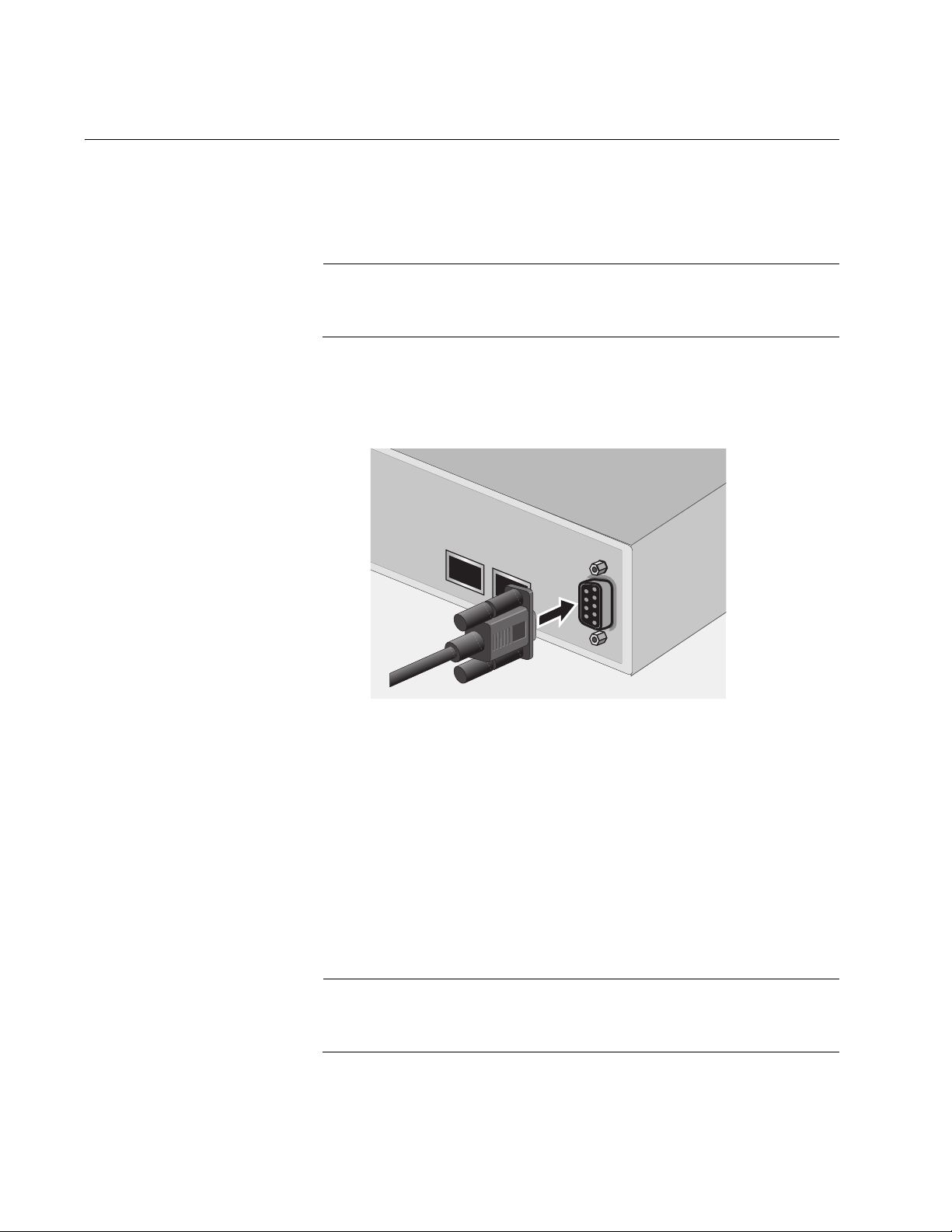
To start a local management session, perform the following procedure:
1. Connect one end of the management cable included with the switch to
the console port on the switch, as shown in Figure 1.
23
24
CONSOLE
Figure 1. Connecting the Management Cable to the Console Port
2. Connect the other end of the cable to the RS-232 port on a terminal or
PC with a terminal emulator program.
3. Configure the terminal or terminal emulator program as follows:
Baud per second: 9600
Data bits: 8
Stop bits: 1
Flow control: None
Note
These settings are for a DEC VT100 or ANSI terminal, or an
equivalent terminal emulation program. They cannot be changed.
28 Section I: Using the Menus Interface
Page 29

AT-S79 Management Software User’s Guide
The Login Menu is shown in Figure 2.
=======================================================
AT-GS950/24 Management System Version AT-S79 V2.0.0
Local - Console
Allied Telesis International Corp.
Copyright 2008
=======================================================
Login Menu
Login:
Figure 2. Login Menu
4. Enter the manager login name and press Return. The default name is
“manager.”
You are prompted for a password.
5. Enter the manager password. The default password is “friend.”
Note
To change the login name or password, refer to “Setting the User
Interface Configuration” on page 40.
The Main Menu is shown in Figure 3.
Main Menu
[G]eneral Information
[B]asic Switch Configuration
[A]dvanced Switch Configuration
Switch [T]ools
[S]tatistics
[Q]uit
Command>
Figure 3. Main Menu
6. Enter the character in square brackets to select an option.
Section I: Using the Menus Interface 29
Page 30

Chapter 2: Getting Started with the Menus Interface
Using the Menus Interface
If you are using a DEC VT00 or ANSI (the default) terminal configuration,
refer to Table 1 for instructions on how to move through the menus and
select menu options.
When directed to You must
Enter your selection Type the menu option letter.
Table 1. Menus Interface Operations
Enter information (for
example, entering a port
number)
Return to previous menu Type Q for Quit to Previous Menu.
When you press Enter to select a field in which you can enter a value, the
“>” symbol is displayed. For example:
Enter new password>
The “>” symbol indicates that you can enter a new value for the parameter
or change the existing value. After you have entered a value, press Enter.
Changes are immediately activated on the AT-GS950 Series switch.
Type the information and press Enter.
30 Section I: Using the Menus Interface
Page 31

Quitting from a Local Management Session
To quit a local management session, return to the Main Menu and type Q
for Quit. When you are finished managing the switch, make sure you exit
from a management session. Quitting from a local session prevents
unauthorized changes to the switch’s configuration if you leave your
workstation unattended.
Note
A local management session automatically times out if there is no
management activity during a pre-defined length of time referred to
as the timeout period. The timeout feature is intended to protect the
parameter settings on the switch from unauthorized changes if you
leave your management station unattended during a management
session. The default timeout value is 10 minutes. To change the
timeout default value, refer to “Setting the User Interface
Configuration” on page 40.
AT-S79 Management Software User’s Guide
Section I: Using the Menus Interface 31
Page 32

Chapter 2: Getting Started with the Menus Interface
32 Section I: Using the Menus Interface
Page 33

Chapter 3
Basic Switch Parameters
This chapter contains the following sections:
“Configuring the IP Address, Subnet Mask, and Gateway Address” on
page 34
“Enabling and Disabling the DHCP Client” on page 37
“Configuring System Administration Information” on page 38
“Setting the User Interface Configuration” on page 40
“Viewing Switch Information” on page 45
“Rebooting the Switch” on page 48
“Pinging a Remote System” on page 50
“Returning the AT-S79 Management Software to the Factory Default
Values” on page 53
“Displaying Statistics” on page 55
Section I: Using the Menus Interface 33
Page 34

Chapter 3: Basic Switch Parameters
Configuring the IP Address, Subnet Mask, and Gateway Address
This procedure explains how to manually assign an IP address, subnet
mask, and gateway address to the switch. Before performing the
procedure, note the following:
An IP address and subnet mask are not required for normal network
operations of the switch. Values for these parameters are only required
if you want to remotely manage the device with a web browser.
A gateway address is only required if you want to remotely manage
the device from a remote management station that is separated from
the switch by a router.
To configure the switch to automatically obtain its IP configuration from
a DHCP server on your network, go to “Enabling and Disabling the
DHCP Client” on page 37.
To set the switch’s IP configuration, perform the following procedure:
1. From the Main Menu, type B to select Basic Switch Configuration.
The Basic Switch Configuration Menu is shown in Figure 4.
Main Menu -> Basic Switch Configuration Menu
System [A]dministration Configuration
System [I]P Configuration
S[N]MP Configuration
[P]ort Configuration
[U]ser Interface Configuration
Rapid [S]panning Tree Configuration
[B]andwidth Control Configuration
IP Access [L]ist
Destination MAC [F]ilter
[Q]uit to previous menu
Command>
Figure 4. Basic Switch Configuration Menu
34 Section I: Using the Menus Interface
Page 35

AT-S79 Management Software User’s Guide
2. From the Basic Switch Configuration Menu, type I to select System IP
Configuration.
The System IP Configuration Menu is shown in Figure 5.
Basic Switch Configuration -> System IP Configuration Menu
MAC Address: 00:06:5H:B2:65:84
IP Address: 0.0.0.0
Subnet Mask: 0.0.0.0
Gateway: 0.0.0.0
DHCP Mode: Disabled
----------------------- <COMMAND> ----------------------------Set [I]P Address
Set Subnet [M]ask
Set Default [G]ateway
Enable/Disable [D]HCP Mode
[Q]uit to previous menu
Command>
3. To set the switch’s IP address, do the following:
Figure 5. System IP Configuration Menu
The top portion of the menu displays the current IP address, subnet
mask, and gateway address for the switch. The menu also displays the
switch’s MAC address. The MAC address cannot be changed. The
menu also displays the current status of the DHCP client on the switch.
The Enable/Disable DHCP Mode option is described in “Enabling and
Disabling the DHCP Client” on page 37.
a. Type I to select Set IP Address.
The following prompt is displayed:
Enter new IP address>
b. Type the IP address for the switch in the format
XXX.XXX.XXX.XXX. Then press Enter.
Section I: Using the Menus Interface 35
Page 36

Chapter 3: Basic Switch Parameters
4. To set the switch’s subnet mask, do the following:
a. Type M to select Set Subnet Mask.
The following prompt is displayed:
Enter new subnet mask>
b. Type the subnet mask for the switch and press Enter.
5. To set the switch’s gateway address, do the following:
a. Type G to select Set Default Gateway.
The following prompt is displayed:
Enter new gateway IP address>
b. Type the gateway IP address for the switch and press Enter.
6. Type Q to select Quit to previous menu and save your changes.
36 Section I: Using the Menus Interface
Page 37

Enabling and Disabling the DHCP Client
This procedure explains how to activate and deactivate the DHCP client
on the switch. When the client is activated, the switch obtains its IP
configuration, such as its IP address and subnet mask, from a DHCP
server on your network. Before performing the procedure, note the
following:
An IP address and subnet mask are not required for normal network
operations of the switch. Values for these parameters are only required
if you want to remotely manage the device with a web browser.
A gateway address is only required if you want to remotely manage the
device from a remote management station that is separated from the
switch by a router.
The DHCP client is disabled by default on the switch.
The DHCP client does not support BOOTP servers.
AT-S79 Management Software User’s Guide
To activate or deactivate the DHCP client on the switch, perform the
following procedure:
1. From the Main Menu, type B to select Basic Switch Configuration.
The Basic Switch Configuration Menu is shown in Figure 4 on page 34.
2. From the Basic Switch Configuration Menu, type I to select System IP
Configuration.
The System IP Configuration Menu is shown in Figure 5 on page 35.
3. Type D to select Enable/Disable DHCP Mode.
The following prompt is displayed:
Enable or Disable DHCP mode (E/D)>
4. Type E to select Enable or D to select Disable.
If you enable the client, it immediately begins to send queries to the
DHCP server. It continues to send queries until it receives a response.
5. Type Q to select Quit to previous menu and save your changes.
Section I: Using the Menus Interface 37
Page 38

Chapter 3: Basic Switch Parameters
Configuring System Administration Information
This section explains how to assign a name to the switch, as well as
specify the location of the switch and the name of the switch’s
administrator. Entering this information is optional.
To set a switch’s administration information, perform the following
procedure:
1. From the Main Menu, type B to select Basic Switch Configuration.
The Basic Switch Configuration Menu is shown in Figure 4 on page 34.
2. From the Basic Switch Configuration Menu, type A to select System
Administration Information.
The System Administration Configuration Menu is shown in Figure 6.
Basic Switch Configuration -> System Admin. Configuration Menu
Description: AT-GS950/16
Name:
Location:
Contact:
----------------------- <COMMAND> ----------------------------Set System [N]ame
Set System [L]ocation
Set System [C]ontact Information
[Q]uit to previous menu
Command>
Figure 6. System Administration Configuration Menu
The Description parameter in the top portion of the menu displays the
model name of the switch. This parameter cannot be changed.
3. To set the system’s name, do the following:
a. Type N to select Set System Name.
The following prompt is displayed:
Enter system name>
38 Section I: Using the Menus Interface
Page 39

AT-S79 Management Software User’s Guide
b. Type a name for the switch (for example, Sales). The name is
optional and can contain up to 50 characters.
Note
Allied Telesis recommends that you assign names to the switches.
Names can help you identify the switches when you manage them
and can also help you avoid performing a configuration procedure
on the wrong switch.
4. To enter the system’s location, do the following:
a. Type L to select Set System Location.
The following prompt is displayed:
Enter system location>
b. Type information to describe the location of the switch (for
instance, Third Floor). The location is optional and can contain up
to 50 characters.
5. To enter the administrator’s name, do the following:
a. Type C to select Set System Contact Information.
The following prompt is displayed:
Enter system contact>
b. Type the name of the network administrator responsible for
managing the switch. The contact name is optional and can
contain up to 50 characters.
6. Type Q to select Quit to previous menu and save your changes.
Section I: Using the Menus Interface 39
Page 40

Chapter 3: Basic Switch Parameters
Setting the User Interface Configuration
This procedure explains how to adjust the user interface and security
features on the switch. With this procedure you can:
Change the console timer, used to automatically end inactive local
management sessions.
Change the AT-S79 management login user name and password.
Enable and disable the web server, used to manage the switch from a
remote management station with a web browser.
For information about how to configure a dial-in user, see Chapter 9, “Dialin User Configuration” on page 95.
To set the switch’s user interface configuration, perform the following
procedure:
1. From the Main Menu, type B to select Basic Switch Configuration.
The Basic Switch Configuration Menu is shown in Figure 4 on page 34.
2. From the Basic Switch Configuration Menu, type U to select User
Interface Configuration.
40 Section I: Using the Menus Interface
Page 41

AT-S79 Management Software User’s Guide
The User Interface Configuration Menu is shown in Figure 7.
Basic Switch Configuration -> User Interface Configuration Menu
Console UI Idle Timeout: 5 Min.
Password Protection: Enabled
SNMP Agent: Enabled
Web Server: Enabled
Administrator List:
No. Username Password No. Username Password
-- -------- -------- -- ------- -------1 manager ****** 2
34
56
78
----------------------- <COMMAND> -----------------------------
Set [C]onsole UI Time Out Enable/Disable [W]eb Server
Enable/Disable [S]NMP Agent [R]ADIUS Server Configuration
[A]dd Administrator [D]elete Administrator
[M]odify Administrator Enable/Disable Password Pr[o]tection
[Q]uit to previous menu
Command>
Figure 7. User Interface Configuration Menu
The RADIUS Server Configuration option is described Chapter 18,
“RADIUS Authentication Protocol” on page 207.
3. To configure the console idle time out parameter, do the following:
a. Type C to select Set Console UI Time Out.
The following prompt is displayed:
Enter console idle timeout>
b. Enter a number for the timeout value. The range is 0 to 60 minutes.
The default is 5 minutes. A timeout value of 0 causes the switch to
never timeout a local management session.
The console idle time out parameter specifies the length of time a
local management session can be inactive before the management
software automatically ends it. The purpose of this parameter is to
prevent unauthorized individuals from configuring the switch
should you leave your management workstation unattended.
Section I: Using the Menus Interface 41
Page 42

Chapter 3: Basic Switch Parameters
This parameter applies to a local management session but not to a
remote web management session. A web browser management
session remains active so long as your web browser is open.
Note
If you select 0, you must always remember to properly log off from a
local management session when you are finished to prevent
blocking future management sessions with the switch.
4. To enable or disable the web server, do the following:
a. Type W to select Enable/Disable Web Server.
The following prompt is displayed:
Enable or Disable web server (E/D)>
b. Type E to enable the web server or D to disable it. The default is
enabled. If you disable the web server, you can not manage the
switch from a remote management station using a web browser.
5. To enable or disable an SNMP agent, do the following:
a. Type S to select SNMP Agent.
The following prompt is displayed:
Enable or Disable SNMP agent (E/D)
b. Type E to enable an SNMP agent or D to disable the SNMP agent.
6. To add a new user and password, do the following:
a. Type A to select Add Administrator.
The following prompt is displayed:
Enter entry number>
b. Enter the number of the user name. You can select numbers 2
through 8.
The following prompt is displayed:
Enter new user name>
c. Enter the name of a user.
The following prompt is displayed:
Enter new password>
42 Section I: Using the Menus Interface
Page 43

AT-S79 Management Software User’s Guide
d. Enter a password for the new user. You are prompted to reenter
the password.
The following prompt is displayed:
Retype new password>
e. Retype the password for the new user.
7. To delete a user name, do the following:
a. Type D to select Delete Administrator.
The following prompt is displayed:
Enter entry number>
b. Enter the number of the user name that you want to delete. After
you enter it, the Administrator List is refreshed.
8. To modify a user name, do the following
a. Type M to select Modify Administrator.
The following prompt is displayed:
Enter entry number>
b. Enter the number of the user name. You can select numbers 2
through 8.
The following prompt is displayed:
Choose which to be modified (U/P/B)>
c. Type U to change the user name.
The following prompt is displayed:
Enter new user name>
d. Enter the name of the new user. Type P to change the password.
The following prompt is displayed:
Enter new password>
e. Type the new password and press Enter. The password can be
from 0 to 12 characters. Allied Telesis recommends not using
special characters, such as spaces and exclamation points. The
password is case sensitive. Not entering a new password deletes
the current password without assigning a new one.
Section I: Using the Menus Interface 43
Page 44

Chapter 3: Basic Switch Parameters
The following prompt is displayed:
Retype new password.
f. Enter the new password a second time. You must use the new
login password the next time you start a local or web browser
management session.
g. To change both the user name and its corresponding password,
type B.
The following prompt is displayed:
Enter new user name>
h. Enter the name of the new user.
The following prompt is displayed:
Enter new password>
i. Enter the new password.
The following prompt is displayed:
Retype new password>
j. Reenter the new password.
9. To enable or disable password protection, type O.
The following prompt is displayed:
Enable or Disable password protection (E/D)?>
a. Type E to enable password protection or D to disable password
protection.
You can control login authentication by enabling password
protection which requires a user to supply a password when
logging onto the switch. If you disable password protection, a user
can login without inputting a password.
10.Type Q to select Quit to previous menu and save your
changes.
44 Section I: Using the Menus Interface
Page 45

Viewing Switch Information
To view general information about the switch, perform the following
procedure:
1. From the Main Menu, type G to select General Information.
The General Information menu is shown in Figure 8.
Main Menu -> General Information
System up for: 24min(s), 36sec(s)
Runtime Image: Version 2.0
Boot Loader: Version 2.0
Hardware Information
Version: DRAM Size: 16MB
Fixed Baud Rate: 9600bps Flash Size: 4 MB
Administration Information
Switch Name: Marketing
Switch Location: Fourth Floor
Switch Contact: Ralph
System Address Information
MAC Address: 00:06:5H:B2:65:84
IP Address: 149.35.8.237
Subnet Mask: 255.255.255.0
Gateway: 149.35.8.1
Automatic Network Features
DHCP Mode: Disabled
AT-S79 Management Software User’s Guide
Press any key to continue...
Figure 8. General Information Menu
The General Information Menu displays the following information:
System up for
The number of hours, minutes, and seconds since the last reset or
power cycle.
Runtime Image
The version of the runtime software.
Boot Loader
The version of the boot loader software.
Section I: Using the Menus Interface 45
Page 46

Chapter 3: Basic Switch Parameters
Hardware Information Section
Version
The hardware version number.
Fixed Baud Rate
The baud rate of the console port.
DRAM Size
The size of the DRAM, in megabytes.
Flash Size
The size of the flash memory, in megabytes.
Administration Information Section
Switch Name
The name assigned to the switch. To assign the switch a name, refer
to “Configuring System Administration Information” on page 38.
Switch Location
The location of the switch. To specify the location, refer to “Configuring
System Administration Information” on page 38.
Switch Contact
The contact person responsible for managing the switch. To specify
the name of a contact, refer to “Configuring System Administration
Information” on page 38.
System Address Information Section
MAC Address
The MAC address of the switch. You cannot change this information.
System IP Address
The IP address of the switch. Refer to “Configuring the IP Address,
Subnet Mask, and Gateway Address” on page 34 to manually assign
an IP address or “Enabling and Disabling the DHCP Client” on
page 37 to activate the DHCP client.
Subnet Mask
The subnet mask for the switch. Refer to “Configuring the IP Address,
Subnet Mask, and Gateway Address” on page 34 to manually assign a
subnet mask or “Enabling and Disabling the DHCP Client” on page 37
to activate the DHCP client.
46 Section I: Using the Menus Interface
Page 47

AT-S79 Management Software User’s Guide
Gateway
Default gateway IP address. Refer to “Configuring the IP Address,
Subnet Mask, and Gateway Address” on page 34 to manually assign a
gateway address or “Enabling and Disabling the DHCP Client” on
page 37 to activate the DHCP client.
Automatic Network Features Section
DHCP Mode
The status of the DHCP client on the switch. For information about
setting this parameter, refer to “Enabling and Disabling the DHCP
Client” on page 37.
2. Press any key to return to the previous menu.
Section I: Using the Menus Interface 47
Page 48

Chapter 3: Basic Switch Parameters
Rebooting the Switch
This procedure reboots the switch and reloads the AT-S79 management
software from flash memory. You might reboot the device if you believe it
is experiencing a problem. Rebooting the device does not change any of
the device’s parameter settings.
To reboot the switch, perform the following procedure:
1. From the Main Menu type T to select Switch Tools.
Caution
The switch does not forward network traffic during the reboot
process. Some network traffic may be lost.
The Switch Tools Configuration Menu is shown in Figure 9.
Main Menu -> Switch Tools Configuration Menu
Software [U]pgrade...
System [R]eboot
[P]ing Execution
[Q]uit to previous menu
Command>
Figure 9. Switch Tools Configuration Menu
2. From the Switch Tools Configuration Menu, type R to select System
Reboot.
48 Section I: Using the Menus Interface
Page 49

AT-S79 Management Software User’s Guide
The System Reboot Menu is shown in Figure 10.
Main Menu -> System Reboot Menu
Reboot Status: Stop
Reboot Type: Normal
---------------------- <COMMAND> ----------------------------
Set Reboot [O]ption
Start [R]eboot Process
[Q]uit to previous menu
Command>
Figure 10. System Reboot Menu
3. From the System Reboot menu, type O to select Set Reboot Option.
The following prompt is displayed:
Select reboot option (F/I/N)>
4. Type N to select Normal.
Note
The F and I options are described in “Returning the AT-S79
Management Software to the Factory Default Values” on page 53.
5. Type R to select Start Reboot Process.
The following prompt is displayed:
Are you sure you want to reboot the system (Y/N)>
6. Type Y to start the reboot process or N to cancel the reboot.
The switch immediately begins to reload the AT-S79 management
software. This process takes approximately one minute to complete.
You can not manage the device during the reboot. After the reboot is
finished, you can log in again if you want to continue to manage the
device.
Section I: Using the Menus Interface 49
Page 50

Chapter 3: Basic Switch Parameters
Pinging a Remote System
This procedure instructs the switch to ping a node on your network. This
procedure is useful in determining whether an active link exists between
the switch and another network device. Note the following before
performing the procedure:
The switch where you are initiating the ping must have an IP address
and subnet mask.
The device you are pinging must be a member of the Default VLAN.
This means that the port on the switch through which the node is
communicating with the switch must be an untagged or tagged
member of the Default VLAN.
To ping a network device, perform the following procedure:
1. From the Main Menu, type T to select Switch Tools.
The Switch Tools Configuration Menu is shown in Figure 9 on page 48.
2. From the Switch Tools Configuration Menu, type P to select Ping
Execution.
The Ping Execution Menu is shown in Figure 11.
Switch Tools Configuration -> Ping Execution
Target IP Address: 0.0.0.0
Number of Requests: 10
Timeout Value (sec): 3
================Result=================
----------------------- <COMMAND> ----------------------------Set Target [I]P Address [E]xecute Ping
Set [N]umber of Requests [S]top Ping
Set [T]imeout Value [Q]uit to previous menu
Command>
Figure 11. Ping Execution Menu
50 Section I: Using the Menus Interface
Page 51

AT-S79 Management Software User’s Guide
3. Type I to select Set Target IP Address.
The following prompt is displayed:
Enter new target IP address>
4. Type the IP address of the node you want the switch to ping and press
Enter.
5. Type N to select Set Number of Requests.
The following prompt is displayed:
Enter new number of requests>
6. Enter the number of ping requests you want the switch to perform. The
range is 1 to 10. The default is 10.
7. Type T to select Set Timeout Value.
The following prompt is displayed:
Enter new timeout value>
8. Enter the length of time in seconds the switch is to wait for a response
before assuming that a ping has failed. The range is 1 to 5 seconds.
The default is 3 seconds.
9. Type E to select Execute Ping.
The following prompt is displayed:
Execute ping or Clean ping data (E/C)>
10. Type E to execute the ping or C to clear previous ping data before
performing this ping.
Section I: Using the Menus Interface 51
Page 52

Chapter 3: Basic Switch Parameters
Switch Tools Configuration -> Ping Execution
Target IP Address: 149.35.8.33
Number of Requests: 4
Timeout Value (sec): 3
================Result=================
----------------------- <COMMAND> ----------------------------Set Target [I]P Address [E]xecute Ping
Set [N]umber of Requests [S]top Ping
Set [T]imeout Value [Q]uit to previous menu
Command>
Figure 12 shows an example of the results of a ping.
No. 1 20 ms
No. 2 20 ms
No. 3 20 ms
No. 4 20 ms
Figure 12. Ping Results
11. To stop the ping, type S to select Stop Ping.
12. Type Q to select Quit to previous menu.
52 Section I: Using the Menus Interface
Page 53

AT-S79 Management Software User’s Guide
Returning the AT-S79 Management Software to the Factory Default Values
This procedure returns all AT-S79 management software parameters to
their default values and deletes all tagged and port-based VLANs on the
switch. The AT-S79 management software default values are listed in
Appendix A, ”AT-S79 Software Default Settings” on page 341.
Caution
This procedure causes the switch to reboot. The switch does not
forward network traffic during the reboot process. Some network
traffic may be lost.
To return the AT-S79 management software to the default settings,
perform the following procedure:
1. From the Main Menu, type T to select Switch Tools.
The Switch Tools Configuration Menu is shown in Figure 9 on page 48.
2. From the Switch Tools Menu, type R to select System Reboot to start
the reboot.
The System Reboot menu is shown in Figure 10 on page 49.
3. Type O to select Set Reboot Option.
The following prompt is displayed:
Select reboot option (F/I/N)>
4. Type F or I to select one of the following:
F (Factory Default)
Resets all switch parameters to the factory default settings, including
IP address, subnet mask, and gateway address.
I (Reset to Defaults Except IP Address)
Resets all switch parameters to the factory default settings, but retains
the IP address, subnet mask, and gateway settings. If the DHCP client
is enabled, it remains enabled after this reset.
Note
Option N is described in “Rebooting the Switch” on page 48.
Section I: Using the Menus Interface 53
Page 54

Chapter 3: Basic Switch Parameters
5. Type R to select Start Reboot Process.
The following prompt is displayed:
Are you sure you want to reboot the system (Y/N)>
6. Type Y to start the reboot process.
The switch returns its operating parameters to the default values and
begins to reload the AT-S79 management software. This process
takes approximately one minute to complete. You can not manage the
device during the reboot. After the reboot is finished, you can log in
again if you want to continue to manage the device.
54 Section I: Using the Menus Interface
Page 55

Displaying Statistics
The procedure in this section describe how to display port statistics.
AT-S79 Management Software User’s Guide
Displaying Port
Statistics
To display port statistics, perform the following procedure:
1. From the Main Menu, type S to select Statistics.
The Statistics Menu is shown in Figure 13.
Main Menu-> Statistics Menu
Port: 1 Elapsed Time Since System Reset: 000:00:11:54
<Counter Name> <Total> <Avg./s>
Total RX Bytes 0 0
Total RX Pkts 0 0
Good Broadcast 0 0
Good Multicast 0 0
CRC/Align Errors 0 0
Undersize Pkts 0 0
Oversize Pkts 0 0
Fragments 0 0
Jabbers 0 0
Collisions 0 0
64-Byte Pkts 0 0
65-127 0 0
128-255 0 0
256-511 0 0
512-1023 0 0
1024-1522 0 0
-------------------------------<COMMAND>-----------------------------[S]elect/[N]ext/[P]rev. Port Since [U]p [R]eset [S]top Refresh [Q]uit
Command>
Figure 13. Statistics Menu
2. Type S to select a port.
The following prompt is displayed:
Select port number>
3. Enter the number of the port whose statistics you want to view. Then
press Return.
Section I: Using the Menus Interface 55
Page 56

Chapter 3: Basic Switch Parameters
4. To display the statistics of the next port, type N for Next.
The statistics for the next port in the sequence is displayed. For
example, if port 2 statistics were displayed, pressing N displays the
statistics for port 3.
5. To display the statistics of the previous port, type P for Previous.
The statistics for the previous port in the sequence is displayed. For
example, if port 6 statistics were displayed, pressing P displays the
statistics for port 5.
6. To view the statistics for the port since the switch has been running,
type U for Since Up.
7. To clear the counters on the port and return them to 0, type R for
Reset.
8. To stop a screen refresh, type T for Stop refresh.
The information in the Statistics Menu is for viewing purposes only.
The statistics are defined below:
Total RX Bytes
Number of bytes received on the port.
Total RX Packets
Number of packets received on the port.
Good Broadcast
Number of valid broadcast packets received on the port.
Good Multicast
Number of valid multicast packets received on the port.
CRC/Align Errors
Number of packets with a cyclic redundancy check (CRC) error but
with the proper length (64-1518 bytes) received on the port.
Undersize Packets
Number of packets that were less than the minimum length specified
by IEEE 802.3 (64 bytes including the CRC) received on the port.
Oversize Packets
Number of packets exceeding the maximum length specified by IEEE
802.3 (1518 bytes including the CRC) received on the port.
Fragments
Number of undersized packets, packets with alignment errors, and
packets with FCS errors (CRC errors) received on the port.
Jabbers
Number of electrical signal errors detected on the port.
56 Section I: Using the Menus Interface
Page 57

AT-S79 Management Software User’s Guide
Collisions
Number of packet collisions on the port.
64-Byte Pkts
The number of 64-Byte packets sent or received by the port. The
minimum length of an Ethernet packet is 64 bytes.
65-127 Pkts
The number of 65-to-127-byte packets sent or received by the port.
128-255 Pkts
The number of 128-to-255-byte packets sent or received by the port.
256-511 Pkts
The number of 256-to-511-byte packets sent or received by the port.
512-1023 Pkts
The number of 512-to-1023-byte packets sent or received by the port.
1024-1518 Pkts
The number of 1024-to-1518-byte packets sent or received by the port.
The maximum length of an Ethernet packet is 1518 bytes.
Section I: Using the Menus Interface 57
Page 58

Chapter 3: Basic Switch Parameters
58 Section I: Using the Menus Interface
Page 59

Chapter 4
Port Configuration
This chapter contains the procedures for viewing and adjusting the
parameter settings for the ports on the switch. This chapter contains the
following sections:
“Displaying the Port Parameters” on page 60
“Enabling and Disabling a Port” on page 63
“Setting a Port’s Speed and Duplex Mode” on page 64
“Changing the Flow Control Setting” on page 66
Section I: Using the Menus Interface 59
Page 60

Chapter 4: Port Configuration
Displaying the Port Parameters
To display the parameter settings for the ports on the switch, perform the
following procedure:
1. From the Main Menu, type B to select Basic Switch Configuration.
The Basic Switch Configuration Menu is shown in Figure 4 on page 34.
2. From the Basic Switch Configuration Menu, type P to select Port
Configuration.
The Port Configuration Menu is shown in Figure 14.
Basic Switch Configuration -> Port Configuration Menu
Port Trunk Type Link Status Mode Flow Ctrl
---- ----- ------ ---- ------ --------------------1 --- 1000tx Up Enabled Auto (100F) Enabled
2 --- 1000tx Up Enabled Auto (100F) Enabled
3 --- 1000tx Up Enabled 100-FDx Enabled
4 --- 1000tx Up Enabled Auto (1000F) Enabled
5 --- 1000tx Up Enabled Auto (100F) Enabled
6 --- 1000tx Down Enabled Auto Enabled
7 --- 1000tx Up Enabled Auto (1000F) Enabled
8 --- 1000tx Down Enabled Auto Enabled
9 --- 1000tx Up Enabled Auto (1000F) Enabled
10 --- 1000tx Up Enabled 100-FDx Enabled
11 --- 1000tx Up Enabled 10-FDx Enabled
12 --- 1000tx Up Enabled Auto (100F) Enabled
----------------------- <COMMAND> ------------------------------------
[N]ext Page Set [S]tatus Set [F]low Control
[P]revious Page Set [M]ode [Q]uit to previous menu
Command>
Figure 14. Port Configuration Menu
60 Section I: Using the Menus Interface
Page 61

AT-S79 Management Software User’s Guide
The Port Configuration Menu displays the following columns of
information about the status of the ports:
Port
The port number.
Trunk
The trunk group number. This column contains the number of the port
trunk if the port is a member of a trunk. To configure a trunk, refer to
Chapter 5, “Port Trunking” on page 67.
Type
The port type. The type for a 10/100/1000Base-TX port is 1000TX. The
port type for an optional fiber optic SFP module is 1000BaseX.
Link
The status of the link between the port and the end node connected to
the port. The possible values are:
Up - A link exists between the port and the end node.
Down - The port has not established a link with an end node.
Status
The current operating status of the port. The possible values are:
Enabled - The port is able to send and receive Ethernet frames. This is
the default setting for all ports on the switch.
Disabled - The port has been manually disabled.
To change a port’s status, see “Enabling and Disabling a Port” on
page 63.
Mode
The port’s speed and duplex mode setting. The possible values are:
Auto - The port is using Auto-Negotiation to set the operating speed
and duplex mode. This is the default setting for all ports. The actual
operating speed and duplex mode of the port are displayed in
parentheses (for example, “Auto (1000F)” for 1000 Mbps full duplex
mode).
If the speed and duplex mode were set manually on a port, mode will
be one of the following:
10-HDx - 10 Mbps in half-duplex mode
100-HDx - 100 Mbps in half-duplex mode
10-FDx - 10 Mbps in full-duplex mode
100-FDx - 100 Mbps in full-duplex mode
Section I: Using the Menus Interface 61
Page 62

Chapter 4: Port Configuration
1000-FDx - 1000 Mbps in full-duplex mode
1000-HDx - 1000 Mbps in half-duplex mode
To change a port’s speed and duplex mode setting, see “Setting a
Port’s Speed and Duplex Mode” on page 64.
Flow Ctrl
Whether flow control is enabled on the port. Flow control is enabled by
default. To disable flow control, refer to “Changing the Flow Control
Setting” on page 66.
3. Type Q to select Quit to previous menu.
62 Section I: Using the Menus Interface
Page 63

Enabling and Disabling a Port
This procedure enables and disables a port. You may want to disable a
port and prevent packets from being forwarded if a problem occurs with
the node or cable connected to the port. After the problem has been fixed,
you can enable the port to resume normal operation. You can also disable
an unused port to secure it from unauthorized connections. The default
setting for a port is enabled.
To change the port’s status, perform the following procedure:
1. From the Main Menu, type B to select Basic Configuration.
The Basic Switch Configuration Menu is shown in Figure 4 on page 34
2. From the Basic Switch Configuration Menu, type P to select Port
Configuration.
The Port Configuration Menu is shown in Figure 14 on page 60.
AT-S79 Management Software User’s Guide
3. Type S to select Set Status.
The following prompt is displayed:
Set Status->Enter port number>
4. Enter the number of the port you want to enable or disable. You can
configure only one port at a time.
The following prompt is displayed:
Enable or Disable port n (E/D)>
5. Type E to enable the port or D to disable it. The default is enabled. A
disabled port immediately stops forwarding all ingress and egress
traffic until you enable it again.
The display is refreshed to show the port’s new status.
6. Type Q to select Quit to previous menu and save your changes.
Section I: Using the Menus Interface 63
Page 64

Chapter 4: Port Configuration
Setting a Port’s Speed and Duplex Mode
To change a port’s speed or duplex mode, perform the following
procedure:
1. From the Main Menu, type B to select Basic Configuration.
The Basic Switch Configuration Menu is shown in Figure 4 on page 34
2. From the Basic Switch Configuration Menu, type P to select Port
Configuration.
The Port Configuration Menu is shown in Figure 14 on page 60.
3. Type M to select Set Mode.
The following prompt is displayed:
Set Mode -> Enter port number >
4. Enter the number of the port whose speed or duplex mode you want to
change. You can configure only one port at a time.
The following prompt is displayed:
Enter new mode for port n (a/h/H/F/f/t/T)>
5. Enter the letter that corresponds to the desired speed and duplex
mode setting for the port. The port settings are:
a - Auto: The port uses Auto-Negotiation to set its speed and duplex
mode. This is the default setting for all ports.
h - 10 Mbps, half-duplex
f - 10 Mbps, full-duplex
H - 100 Mbps, half-duplex
F - 100 Mbps, full-duplex
When selecting a setting, note the following:
When a twisted-pair port on the switch is set to Auto-Negotiation,
the default setting, you must set the end node to Auto-Negotiation
to prevent a duplex mode mismatch. A switch port using AutoNegotiation defaults to half-duplex if it detects that the end node is
not using Auto-Negotiation. This can result in a mismatch if the end
node is operating at a fixed duplex mode of full-duplex. To avoid
this problem when connecting an end node with a fixed duplex
mode of full-duplex to a switch port, disable Auto-Negotiation on
the port and set the port’s speed and duplex mode manually.
64 Section I: Using the Menus Interface
Page 65

AT-S79 Management Software User’s Guide
Allied Telesis does not recommend manually setting a 10/100/
1000Base-T twisted-pair port to either 1000 Mbps full duplex or
1000 Mbps half duplex. For 1000 Mbps operation, Allied Telesis
recommends setting a port to Auto-Negotiation.
The only valid setting for an optional SFP port is Auto-Negotiation.
6. Type Q to select Quit to previous menu and save your changes.
Section I: Using the Menus Interface 65
Page 66

Chapter 4: Port Configuration
Changing the Flow Control Setting
Flow control applies to ports operating in full-duplex mode. A switch port
uses flow control to control the flow of ingress packets from its end node.
A port using flow control issues a special frame, referred to as a PAUSE
frame, as specified in the IEEE 802.3x standard, to stop the transmission
of data from an end node. When a port needs to stop an end node from
transmitting data, it issues this frame. The frame instructs the end node to
cease transmission. The port continues to issue PAUSE frames until it is
ready again to receive data from the end node.
To change the flow control setting on a port, perform the following
procedure:
1. From the Main Menu, type B to select Basic Configuration.
The Basic Switch Configuration Menu is shown in Figure 4 on page 34
2. From the Basic Switch Configuration Menu, type P to select Port
Configuration.
The Port Configuration Menu is shown in Figure 14 on page 60.
3. Type F to select Flow Control.
The following prompt is displayed:
Set Flow Control -> Enter port number >
4. Enter the port number whose flow control setting you want to change.
You can configure only one port at a time.
The following prompt is displayed:
Enable or Disable flow control for port <n> (E/D)>
5. Type E to enable flow control or D to disable it. The default is enabled.
The display is refreshed to show the port’s new flow control setting.
6. Type Q to select Quit to previous menu and save your changes.
66 Section I: Using the Menus Interface
Page 67

Chapter 5
Port Trunking
This chapter provides information and procedures for creating a port trunk
and contains the following sections:
“Port Trunking Overview” on page 68
“Creating a Port Trunk” on page 70
“Modifying a Port Trunk” on page 73
“Enabling and Disabling a Port Trunk” on page 74
Section I: Using the Menus Interface 67
Page 68

Chapter 5: Port Trunking
Port Trunking Overview
A port trunk is an economical way for you to increase the bandwidth
between the Ethernet switch and another networking device, such as a
network server, router, workstation, or another Ethernet switch. A port
trunk is a group of ports that have been grouped together to function as
one logical path. A port trunk increases the bandwidth between the switch
and the other network device and is useful in situations where a single
physical link between the devices is insufficient to handle the traffic load.
Static Port Trunk
Overview
AT-G S950/24 24-Port 10/100/1000Mbps + 2 SFP Combo WebSmart Switch
1 3 5791113 15 17 19 21 23
POWER
2 4 6 8 10 12 14 16 18 20 22 24 23 24
SPEED
LINK/ACT
SPEED
LINK/ACT
A static port trunk consists of two to eight ports on the switch that function
as a single virtual link between the switch and another device. A static port
trunk improves performance by distributing the traffic across multiple ports
between the devices and enhances reliability by reducing the reliance on a
single physical link.
A static trunk is easy to configure. You simply designate the ports on the
switch that are to be in the trunk and the management software on the
switch automatically groups them together.
The example in Figure 15 illustrates a static port trunk of four links
between two AT-GS950/48 Gigabit Ethernet Smart Switches.
LINK/ACT
AT-G S950/24 24-Port 10/100/1000Mbps + 2 SFP Combo WebSmart Switch
1 3 5791113 15 17 19 21 23
POWER
2 4 6 8 10 12 14 16 18 20 22 24 23 24
SPEED
LINK/ACT
SPEED
LINK/ACT
LINK/ACT
1306
Figure 15. Static Port Trunk Example
Network equipment vendors tend to employ different techniques to
implement static trunks. Consequently, a static trunk on one device might
not be compatible with the same feature on a device from a different
68 Section I: Using the Menus Interface
Page 69

AT-S79 Management Software User’s Guide
manufacturer. For this reason static trunks are typically employed only
between devices from the same vendor. That is not to say that an Allied
Telesis layer 2 managed switch cannot form a static trunk with a device
from another manufacturer; but there is the possibility that the
implementations of static trunking on the two devices might not be
compatible.
Also, note that a static trunk does not provide for redundancy or link
backup. If a port in a static trunk loses its link, the trunk’s total bandwidth is
diminished. Although the traffic carried by the lost link is shifted to one of
the remaining ports in the trunk, the bandwidth remains reduced until the
lost link is reestablished or you reconfigure the trunk by adding another
port to it.
Static Port Trunk Guidelines
Following are the guidelines for creating a static trunk:
Allied Telesis recommends setting static port trunks between Allied
Telesis networking devices to ensure compatibility. While an
Allied Telesis device may be able to form a static trunk with a device
from another equipment vendor, it is possible that the implementation
of this feature on the two devices may not be compatible, resulting in
undesired switch behavior.
A static trunk can contain up to eight ports.
The ports of a static trunk must be of the same medium type. They can
be all twisted-pair ports or all fiber optic ports.
The ports of a trunk can be either consecutive (for example Ports 5-9)
or nonconsecutive (for example, ports 4, 8, 11, 20).
Before creating a port trunk, examine the speed, duplex mode, flow
control, and back pressure settings of all of the ports that will be
included in the trunk. Verify that the settings are the same for all ports
in the trunk. If these settings are not the same, then the switch will not
allow you to create the trunk.
After you have created a port trunk, a change to the speed, duplex
mode, flow control, or back pressure of any port in the trunk
automatically implements the same change on all the other member
ports.
A port can belong to only one static trunk at a time.
The ports of a static trunk can be untagged or untagged members of
the same VLAN.
The switch selects a port in the trunk to handle broadcast packets and
packets of unknown destination. The switch makes this choice based on a
hash algorithm, depending upon the source and destination MAC
addresses.
Section I: Using the Menus Interface 69
Page 70

Chapter 5: Port Trunking
Creating a Port Trunk
This procedure explains how to create a port trunk.
To create a port trunk, perform the following procedure:
1. From the Main Menu, type A to select Advanced Switch
Configuration.
The Advanced Switch Configuration Menu is shown in Figure 16.
Caution
Do not connect the cables to the ports on the switches until you
have configured the trunk with the management software.
Connecting the cables before configuring the software creates a
loop in your network topology, which can result in broadcast storms
and poor network performance.
Main Menu -> Advanced Switch Configuration Menu
[V]LAN Management
[T]runk Configuration
[I]GMP Snooping Configuration
Static Multicast [A]ddress Configuration
Quality of [S]ervice Configuration
Port [M]irroring Configuration
[D]ial-in User Configuration
802.1[X] Port Based Access Control Configuration
[Q]uit to previous menu
Command>
Figure 16. Advanced Switch Configuration Menu
2. From the Advanced Switch Configuration Menu, type T to select
Trunk Configuration.
70 Section I: Using the Menus Interface
Page 71

AT-S79 Management Software User’s Guide
The Trunk Configuration Menu is shown in Figure 17.
Advanced Switch Configuration -> Trunk Configuration Menu
Group Status Port Members Trunk ID
------- -------------- --------------------- ---------1 Disabled 1
2 Disabled 2
3 Disabled 3
4 Disabled 4
5 Disabled 5
6 Disabled 6
7 Disabled 7
----------------------- <COMMAND> -----------------------------
[A]dd Trunk Member [S]et Trunk Status
[R]emove Trunk Member [Q]uit to previous menu
Command>
Figure 17. Trunk Configuration Menu
3. From the Trunk Configuration Menu, type A to select Add Trunk
Member.
The following prompt is displayed:
Enter trunk group number>
4. Select a trunk group number from 1 to 7 and press Enter.
The following prompt is displayed:
Enter port members (up to 8 ports) for trunk n >
5. Enter the ports you want to include in the trunk and press Enter.
You can specify the ports individually separated by commas (for
example, 1,2,5), as a range of ports separated by a hyphen (for
example, 2-4), or both (for example, 4,6,11-14).
6. Type S to select Set Trunk Status.
The following prompt is displayed:
Enter trunk group number>
7. Type the trunk group number and press Enter.
Section I: Using the Menus Interface 71
Page 72

Chapter 5: Port Trunking
The following prompt is displayed:
Enable or Disable trunk group number n (E/D)>
8. Type E to enable the trunk.
9. Type Q to select Quit to previous menu and save your changes.
The trunk is now operational on the switch.
10. Configure the port trunk on the other switch and connect the cables.
72 Section I: Using the Menus Interface
Page 73

Modifying a Port Trunk
This procedure adds and removes ports from a port trunk.
Caution
Before modifying a trunk, disconnect the cables from the ports of the
trunk. Adding or removing ports from a trunk without first
disconnecting the cables can create loops in your network topology,
which can cause poor network performance and broadcast storms.
To add or remove ports from a trunk, perform the following procedure:
1. From the Main Menu, type A to select Advanced Switch
Configuration.
The Advanced Switch Configuration Menu is shown in Figure 16 on
page 70.
AT-S79 Management Software User’s Guide
2. From the Advanced Switch Configuration Menu, type T to select Trunk
Configuration.
The Trunk Configuration Menu is shown in Figure 17 on page 71.
3. To add ports to a port trunk, type A to select Add Trunk Member. To
remove ports, type R to select Remove Trunk Member.
The following prompt is displayed:
Enter trunk group number>
4. Type the number of the trunk group you want to modify and press
Enter.
The following prompt is displayed:
Enter port members (up to 8 ports) for trunk <n>>
5. Type the ports you want to add or remove from the trunk and press
Enter.
You can specify the ports individually separated by commas (for
example, 1,2,5), as a range of ports separated by a hyphen (for
example, 2-4), or both (for example, 4,6,11-14).
6. Type Q to select Quit to previous menu and save your changes.
7. Modify the port trunk on the other switch and reconnect the cables.
Section I: Using the Menus Interface 73
Page 74

Chapter 5: Port Trunking
Enabling and Disabling a Port Trunk
This procedure enables and disables a port trunk. Note the following
before performing this procedure:
Do not enable a port trunk until after you have configured the trunk on
both switches.
Do not connect the cables to the ports on the switches until after you
have configured and enabled the trunk on both switches.
Caution
Before disabling a port trunk, first disconnect all cables from the
ports of the trunk. Leaving the cables connected can create loops in
your network topology because the ports of a disabled port trunk
function as normal network ports, forwarding individual network
traffic.
To enable or disable a port trunk, perform the following procedure:
1. From the Main Menu, type A to select Advanced Switch
Configuration.
The Advanced Switch Configuration Menu is shown in Figure 16 on
page 70.
2. From the Advanced Switch Configuration Menu, type T to select
Trunk Configuration.
The Trunk Configuration Menu is shown in Figure 17 on page 71.
3. From the Trunk Configuration Menu, type S to select Set Trunk
Status.
The following prompt is displayed:
Enter trunk group number>
4. Type the number of the trunk group you want to enable or disable and
press Enter.
The following prompt is displayed:
Enable or Disable trunk group number n (E/D)>
5. Type E to enable the trunk or D to disable it.
6. Type Q to select Quit to previous menu and save your changes.
74 Section I: Using the Menus Interface
Page 75

Chapter 6
IGMP Snooping
This chapter explains how to activate and configure the Internet Group
Management Protocol (IGMP) snooping feature on the switch. Sections in
the chapter include:
“IGMP Snooping Overview” on page 76
“Configuring IGMP Snooping” on page 78
Section I: Using the Menus Interface 75
Page 76

Chapter 6: IGMP Snooping
IGMP Snooping Overview
IGMP enables IPv4 routers to create lists of nodes that are members of
multicast groups. (A multicast group is a group of end nodes that want to
receive multicast packets from a multicast application.) The router creates
a multicast membership list by periodically sending out queries to the local
area networks connected to its ports.
A node that wants to become a member of a multicast group responds to a
query by sending a report. A report indicates an end node’s desire to
become a member of a multicast group. Nodes that join a multicast group
are referred to as host nodes. After becoming a member of a multicast
group, a host node must continue to periodically issue reports to remain a
member.
After the router has received a report from a host node, it notes the
multicast group that the host node wants to join and the port on the router
where the node is located. Any multicast packets belonging to that
multicast group are then forwarded by the router out the port. If a particular
port on the router has no nodes that want to be members of multicast
groups, the router does not send multicast packets out the port. This
improves network performance by restricting multicast packets only to
router ports where host nodes are located.
There are three versions of IGMP — versions 1, 2, and 3. One of the
differences between the versions is how a host node signals that it no
longer wants to be a member of a multicast group. In version 1 it stops
sending reports. If a router does not receive a report from a host node
after a predefined length of time, referred to as a time-out value, it
assumes that the host node no longer wants to receive multicast frames,
and removes it from the membership list of the multicast group.
In version 2 a host node exits from a multicast group by sending a leave
request. After receiving a leave request from a host node, the router
removes the node from appropriate membership list. The router also stops
sending multicast packets out the port to which the node is connected if it
determines there are no further host nodes on the port.
Version 3 adds the ability of host nodes to join or leave specific sources in
a multicast group.
The IGMP snooping feature on the AT-GS950 switches support IGMP
versions 1 and 2. The switch monitors the flow of queries from a router
and reports and leave messages from host nodes to build its own
multicast membership lists. It uses the lists to forward multicast packets
only to switch ports where there are host nodes that are members of
multicast groups. This improves switch performance and network security
by restricting the flow of multicast packets only to those switch ports
connected to host nodes.
76 Section I: Using the Menus Interface
Page 77

AT-S79 Management Software User’s Guide
Without IGMP snooping a switch would have to flood multicast packets out
all of its ports, except the port on which it received the packet. Such
flooding of packets can negatively impact network performance.
The AT-GS950 switches maintain a list of multicast groups through an
adjustable timeout value, which controls how frequently it expects to see
reports from end nodes that want to remain members of multicast groups,
and by processing leave requests.
Note
By default, IGMP snooping is disabled on the switch.
Section I: Using the Menus Interface 77
Page 78

Chapter 6: IGMP Snooping
Configuring IGMP Snooping
The procedures in this section describe how to enable or disable IGMP
snooping, set the age-out timer, and view group members. See the
following procedures:
“Enabling or Disabling IGMP Snooping” on page 78
“Setting the Age-out Timer” on page 80
“Setting Group Members” on page 80
Enabling or
Disabling IGMP
Snooping
Main Menu -> Advanced Switch Configuration Menu
[V]LAN Management
[T]runk Configuration
[I]GMP Snooping Configuration
Static Multicast [A]ddress Configuration
Quality of [S]ervice Configuration
Port [M]irroring Configuration
[D]ial-in User Configuration
802.1[X] Port Based Access Control Configuration
[Q]uit to previous menu
Command>
To activate or deactivate IGMP snooping on the switch, perform the
following procedure:
1. From the Main Menu, type A to select Advanced Switch
Configuration.
The Advanced Switch Configuration Menu is shown in Figure 18.
Figure 18. Advanced Switch Configuration Menu
2. From the Advanced Switch Configuration Menu, type I to select IGMP
Snooping Configuration.
78 Section I: Using the Menus Interface
Page 79

AT-S79 Management Software User’s Guide
The IGMP Snooping Configuration Menu is shown in Figure 19.
Advanced Switch Configuration -> IGMP Snooping Configuration Menu
IGMP Snooping Status: Disabled
IGMP Snooping Age-Out Timer: 280 seconds
Multicast Group Address
-----------------------
-------------------------------<COMMAND>-----------------------------[N}ext Page [E]nable/Disable IGMP Snooping
[P]revious Page [S]et Age-Out Timer
[V]iew Group Members [Q]uit to previous menu
Command>
Figure 19. IGMP Snooping Configuration Menu
3. From the SNMP Configuration Menu, type E to select Enable/Disable
IGMP Configuration.
The following prompt is displayed:
Enable or Disable IGMP snooping (E/D) >
4. Type E to enable IGMP snooping or D to disable IGMP snooping.
By default, IGMP snooping is disabled.
5. Type Q to select Quit to previous menu and save your changes.
Section I: Using the Menus Interface 79
Page 80

Chapter 6: IGMP Snooping
Setting the Age-
out Timer
Use the following procedure to set the age-out timer.
1. From the Main Menu, type A to select Advanced Switch
Configuration.
The Advanced Switch Configuration Menu is shown in Figure 18 on
page 78.
2. From the Advanced Switch Configuration Menu, type I to select IGMP
Snooping Configuration.
The IGMP Configuration Menu is shown in Figure 19 on page 79.
3. From the SNMP Configuration Menu, type S to select Set Age-Out
Timer.
The following prompt is displayed:
Enter age-out time>
For an IGMP member port, the Set Age-Out Timer is set to 280
seconds by default. The range of this parameter is from 280 to
420 seconds.
For an IGMP router port, the Set Age-Out Timer is set to 130 seconds
by default. This value cannot be changed.
Setting Group
Members
4. Type the number of seconds that you want the switch to wait before it
purges an inactive dynamic MAC address which is called the aging
time. Enter a value between 280 and 420 seconds.
5. Type Q to select Quit to previous menu and save your changes.
To set the MAC addresses of IGMP group members, perform the following
procedure:
1. From the Main Menu, type A to select Advanced Switch
Configuration.
The Advanced Switch Configuration Menu is shown in Figure 18 on
page 78.
2. From the Advanced Switch Configuration Menu, type I to select IGMP
Configuration.
The IGMP Configuration Menu is shown in Figure 19 on page 79.
3. From the IGMP Configuration Menu, type V to select View Group
Members.
80 Section I: Using the Menus Interface
Page 81

AT-S79 Management Software User’s Guide
The following prompt is displayed:
Enter MAC Address (xx:xx:xx:xx:xx:xx)>
4. Enter a Multicast Group MAC address in the format xx:xx:xx:xx:xx.
The range of the multicast MAC address is from 01:00:5E:00:01:00 to
01:00:5E:7F:FF:FF.
The IGMP Configuration Menu is updated with the information.
5. Type Q to select Quit to previous menu and save your changes.
Section I: Using the Menus Interface 81
Page 82

Chapter 6: IGMP Snooping
82 Section I: Using the Menus Interface
Page 83

Chapter 7
Static Multicast Address
This chapter explains how to assign static multicast addresses. Sections in
the chapter include:
“Static Multicast Address Overview” on page 84
“Creating a Static Multicast Address” on page 85
Section I: Using the Menus Interface 83
Page 84

Chapter 7: Static Multicast Address
Static Multicast Address Overview
There are 4 ways to populate the database of a MAC address table:
Static unicast addresses which can only be assigned to one port
Static multicast addresses which can be assigned to multiple ports
Broadcast addresses which are broadcast to all of the ports on a
switch
Dynamically learned MAC addresses
If you want the MAC address table to act as a forwarding database,
configure it with static multicast MAC addresses.
The Static Multicast Address feature allows you to assign an IP address to
more than one host. This feature is used for video streaming when you
also enable IGMP snooping. For more information about configuring IGMP
snooping, see Chapter 6, “IGMP Snooping” on page 75.
For the static multicast address, the MAC addresses are prelearned. This
means that you can assign a MAC address before you create a physical
connection to a host.
84 Section I: Using the Menus Interface
Page 85

Creating a Static Multicast Address
The procedures in this section describe how to create, delete, and modify
static multicast addresses. See the following procedures:
“Adding a Static Multicast Address” on page 85
“Deleting a Static Group” on page 86
“Deleting a Static Member Port” on page 87
AT-S79 Management Software User’s Guide
Adding a Static
Multicast
Address
To assign a static multicast address or to assign a group number to an
existing group MAC address, perform the following procedure:
1. From the Main Menu, type A to select Advanced Switch
Configuration.
The Advanced Switch Configuration Menu is shown in Figure 16 on
page 70.
2. From the Advanced Switch Configuration Menu, type A to select Static
Multicast Address Configuration.
The Static Multicast Address Table Menu is shown in Figure 20.
Advanced Switch Configuration -> Static Multicast Address Table Menu
Group MAC Address Group Members
----------------- -------------------------------------------01:00:5E:00:01:00 1
01:00:5E:00:01:01 2
01:00:5E:00:01:02 3, 4,5,6
01:00:5E:00:01:03 7, 8, 9, 10, 11, 12, 13, 14, 15, 16, 17, 18
01:00:5E:00:01:04 19, 20
01:00:5E:00:01:05 21
01:00:5E:00:01:06 22
-------------------------------<COMMAND>-----------------------------[N}ext Page [A]dd Static Member Port Delete Static [G]roup
[P]revious Page [D]elete Static Member Port [Q]uit to previous menu
Command>
Figure 20. Static Multicast Address Table Menu
3. Type A to select Add Static Member Port.
Section I: Using the Menus Interface 85
Page 86

Chapter 7: Static Multicast Address
The following prompt is displayed:
Enter MAC address for multicast entry >
4. Type a multicast MAC address. Then press enter. The range of
acceptable multicast MAC addresses is from 01:00:5E:00:01:00 to
01:00:5E:7F:FF:FF.
The following prompt is displayed:
Select group member >
5. Enter a group member in the range of 1 to 24.
You can add more than one group member at a time. You can specify
the values individually (for example, 2,5,11), as a range (for example,
4-7), or both (for example., 2,5,11-15).
6. Type Q to select Quit to previous menu and save your changes.
Deleting a Static
Group
To delete a group from a Group MAC address, perform the following
procedure.
1. From the Main Menu, type A to select Advanced Switch
Configuration.
The Advanced Switch Configuration Menu is shown in Figure 16 on
page 70.
2. From the Advanced Switch Configuration Menu, type A to select
Static Multicast Address Configuration.
The Static Multicast Address Table Menu is shown in Figure 20 on
page 85.
3. Type G to select Delete Static Group.
The following prompt is displayed:
Enter MAC address for multicast entry >
4. Type a multicast MAC address. Then press enter. The range of
acceptable multicast MAC addresses is from 01:00:5E:00:01:00 to
01:00:5E:7F:FF:FF.
The following prompt is displayed:
Select group member >
5. Enter a group member in the range of 1 to 24.
86 Section I: Using the Menus Interface
Page 87

AT-S79 Management Software User’s Guide
You can add more than one group member at a time. You can specify
the values individually (for example, 2,5,11), as a range (for example,
4-7), or both (for example., 2,5,11-15).
6. Type Q to select Quit to previous menu and save your changes.
Deleting a Static
Member Port
To delete a group from a Group MAC address, perform the following
procedure.
1. From the Main Menu, type A to select Advanced Switch
Configuration.
The Advanced Switch Configuration Menu is shown in Figure 16 on
page 70.
2. From the Advanced Switch Configuration Menu, type A to select Static
Multicast Address Configuration.
The Static Multicast Address Table Menu is shown in Figure 20 on
page 85.
3. Type D to select Delete Static Member Port.
The following prompt is displayed:
Enter MAC address for multicast entry >
4. Type a multicast MAC address. Then press enter. The range of
acceptable multicast MAC addresses is from 01:00:5E:00:01:00 to
01:00:5E:7F:FF:FF.
The following prompt is displayed:
Select group member >
5. Enter a group member in the range of 1 to 24.
You can add more than one group member at a time. You can specify
the values individually (for example, 2,5,11), as a range (for example,
4-7), or both (for example., 2,5,11-15).
6. Type Q to select Quit to previous menu and save your changes.
Section I: Using the Menus Interface 87
Page 88

Chapter 7: Static Multicast Address
88 Section I: Using the Menus Interface
Page 89

Chapter 8
Port Mirroring
This chapter contains the procedure for setting up port mirroring. Port
mirroring allows you to unobtrusively monitor the ingress and egress traffic
on a port by having the traffic copied to another port. This chapter contains
the following sections:
“Port Mirroring Overview” on page 90
“Configuring Port Mirroring” on page 91
“Disabling Port Mirroring” on page 93
Section I: Using the Menus Interface 89
Page 90

Chapter 8: Port Mirroring
Port Mirroring Overview
The port mirroring feature allows you to unobtrusively monitor the traffic
received and transmitted on one or more ports by copying the traffic to
another switch port. You can connect a network analyzer to the port where
the traffic is being copied and monitor the traffic on the other ports without
impacting network performance or speed.
The port(s) whose traffic you want to mirror is called the source port(s).
The port where the traffic will be copied to is called the monitor port.
Observe the following guidelines when you create a port mirror:
You can select more than one source port at a time. However, the
more ports you mirror, the less likely the monitor port is able to handle
all the traffic. For example, if you mirror the traffic of six heavily active
ports, the destination port is likely to drop packets, meaning that it will
not provide an accurate mirror of the traffic of the six source ports.
The source and monitor ports must be located on the same switch.
You can mirror either the ingress or egress traffic of the source ports,
or both.
90 Section I: Using the Menus Interface
Page 91

Configuring Port Mirroring
To set up port mirroring, perform the following procedure:
1. From the Main Menu, type A to select Advanced Switch
Configuration.
The Advanced Switch Configuration Menu is shown in Figure 16 on
page 70.
2. From the Advanced Switch Configuration Menu, type M to select Port
Mirroring Configuration.
The Port Mirroring Menu is shown in Figure 21.
Advanced Switch Configuration -> Port Mirroring Configuration Menu
Status: Disabled
Mirroring Port: 1
Ingress Port:
Egress Port:
AT-S79 Management Software User’s Guide
----------------------- <COMMAND> ----------------------------[S]et Mirroring Port
Set [M]irrored Port
[E]nable/Disable Port Mirroring
[Q]uit to previous menu
Command>
Figure 21. Port Mirroring Menu
3. Type S to select Set Mirroring Port.
The following prompt is displayed:
Set monitoring port-> Enter port number>
4. Type the number of the port where the network analyzer is connected
and press Enter. You can specify only one port.
5. Type M to select Set Mirrored Port.
The following prompt is displayed:
Set monitored port-> Enter port number>
6. Type the number of the port whose ingress and egress traffic you want
to monitor and press Enter. You can specify only one port.
Section I: Using the Menus Interface 91
Page 92

Chapter 8: Port Mirroring
7. Type E to select Enable/Disable Port Mirroring.
The following prompt is displayed:
Enable or Disable monitoring (E/D)>
8. Type E to enable port mirroring.
You can now connect your data analyzer to the mirroring port.
9. Type Q to select Quit to previous menu and save your changes.
92 Section I: Using the Menus Interface
Page 93

Disabling Port Mirroring
To disable port mirroring, perform the following procedure:
1. From the Main Menu, type A to select Advanced Switch
Configuration.
The Advanced Switch Configuration Menu is shown in Figure 16 on
page 70.
2. From the Advanced Switch Configuration Menu, type M to select Port
Mirroring Configuration.
The Port Mirroring Menu is shown in Figure 21 on page 91.
3. Type E to select Enable/Disable Port Mirroring.
The following prompt is displayed:
AT-S79 Management Software User’s Guide
Enable or Disable monitoring (E/D)>
4. Type D to disable port mirroring.
The port that was functioning as the mirroring port can now be used as
a normal networking port.
5. Type Q to select Quit to previous menu and save your changes.
Section I: Using the Menus Interface 93
Page 94

Chapter 8: Port Mirroring
94 Section I: Using the Menus Interface
Page 95

Chapter 9
Dial-in User Configuration
This chapter explains how to assign a user name, password, and VLAN to
a dial-in user. This chapter contains the following sections:
“Dial-in User Configuration Overview” on page 96
“Configuring a Dial-in User” on page 97
Section I: Using the Menus Interface 95
Page 96

Chapter 9: Dial-in User Configuration
Dial-in User Configuration Overview
The Dial-in User Configuration feature allows you to add, delete, and
modify dial-in users to the AT-GS950 switch. In addition, you must assign
each dial-in user to a VLAN. See Chapter 10, “Virtual LANs” on page 101
for more information about VLANs and VIDs.
The purpose of the Dial-in User feature in local mode is to configure user
authentication data when 802.1x ports are operating in local mode. In the
local mode, the switch uses its own authentication data to authenticate a
user.
Note
In local mode, the switch does not authenticate through a RADIUS
server.
To configure a system administrator or set user information for the switch,
see Chapter 3, “Basic Switch Parameters” on page 33.
96 Section I: Using the Menus Interface
Page 97

Configuring a Dial-in User
The procedures in this section describe how to create, delete, and modify
dial-in users. See the following procedures:
“Adding a Dial-in User” on page 97
“Deleting a Dial-in User” on page 98
“Modifying a Dial-in User” on page 100
AT-S79 Management Software User’s Guide
Adding a Dial-in
User
Advanced Switch Configuration -> Dial-in User Configuration Menu
User Name Password Dynamic VLAN
----------------- ----------------------- -----------------Jenny ***** 2
Jill ******* 2
Ellen ***** 3
MaryAnn ****** 3
Tom ***** 3
Sam ***** 1
For each dial-in user, you must assign a user name, password, and VLAN.
To add a dial-in user, perform the following procedure:
1. From the Main Menu, type A to select Advanced Switch
Configuration.
The Advanced Switch Configuration Menu is shown in Figure 16 on
page 70.
2. From the Advanced Switch Configuration Menu, type D to select
Dial-in User Configuration.
The Dial-in User Configuration Menu is shown in Figure 22.
-------------------------------<COMMAND>-----------------------------[N]ext Page [D]elete User
[P]revious Page [M]odify User
[A]dd User [Q]uit to previous menu
Command>
Figure 22. Dial-in User Configuration Menu
Section I: Using the Menus Interface 97
Page 98

Chapter 9: Dial-in User Configuration
3. Type A to select Add User.
The following prompt is displayed:
Enter dial-in user name >
4. Type a name of a dial-in user. Then press Enter.
You can enter up to 23 alphanumeric characters. Special characters
are permitted.
The following prompt is displayed:
Enter dial-in user password >
5. Type the password of the dial-in user.
You can enter up to 23 alphanumeric characters. Special characters
are permitted.
The following prompt is displayed:
Deleting a Dial-in
User
Enter dial-in user dynamic VLAN ID >
6. Assign the dial-in user to a VLAN by entering a VID.
The range for the VID is from 1 to 4,000.
7. Type Q to select Quit to previous menu and save your changes.
To delete a dial-in user, perform the following procedure.
1. From the Main Menu, type A to select Advanced Switch
Configuration.
The Advanced Switch Configuration Menu is shown in Figure 16 on
page 70.
2. From the Advanced Switch Configuration Menu, type D to select
Dial-in User Configuration.
The Dial-in User Configuration Menu is shown in Figure 22 on page
97.
3. Type type D to select Delete User.
The following prompt is displayed:
Enter dial-in user name >
98 Section I: Using the Menus Interface
Page 99

AT-S79 Management Software User’s Guide
4. Type the name of the dial-in user that you want to delete.
The dial-in user name is removed from the Dial-in User Configuration
Menu.
5. Type Q to select Quit to previous menu and save your changes.
Section I: Using the Menus Interface 99
Page 100

Chapter 9: Dial-in User Configuration
Modifying a Dial-
in User
This procedure explains how to modify an existing Dial-in User on the
switch. For each user, you may change the password and the VLAN
assignment. However, you cannot change the user name.
To modify a Dial-in user, perform the following procedure:
1. From the Main Menu, type A to select Advanced Switch
Configuration.
The Advanced Switch Configuration Menu is shown in Figure 16 on
page 70.
2. From the Advanced Switch Configuration Menu, type D to select
Dial-in User Configuration.
The Dial-in User Configuration Menu is shown in Figure 22 on page
97.
3. Type type M to select Modify User.
The following prompt is displayed:
Enter dial-in user name >
4. Type the name of the dial-in user that you want to modify.
The following prompt is displayed:
Enter dial-in user password >
5. Type the password of the dial-in user. You may type in a new
password or the existing password.
The following prompt is displayed:
Enter dial-in user dynamic VLAN ID >
6. Type the VID of the dial-in user. You may type in a new VID or the
existing VID.
7. Type Q to select Quit to previous menu and save your changes.
100 Section I: Using the Menus Interface
 Loading...