

Page 1

CONVERTEON™ Family
Management Software
AT-S70
User’s Guide
CONVERTEON™ Family Media Converter Products
Version 1.2.0
613-50581-00 Rev. C
Page 2

Copyright © 2005 Allied Telesyn, Inc.
All rights reserved. No part of this publication may be reproduced without prior written permission from Allied Telesyn, Inc.
Microsoft and Internet Explorer are registered trademarks of Microsoft Corporation. Netscape Navigator is a registered trademark of
Netscape Communications Corporation. All other product names, company names, logos or other designations mentioned herein are
trademarks or registered trademarks of their respective owners.
Allied Telesyn, Inc. reserves the right to make changes in specifications and other information contained in this document without prior
written notice. The information provided herein is subject to change without notice. In no event shall Allied Telesyn, Inc. be liable for any
incidental, special, indirect, or consequential damages whatsoever, including but not limited to lost profits, arising out of or related to this
manual or the information contained herein, even if Allied Telesyn, Inc. has been advised of, known, or should have known, the possibility
of such damages.
Page 3

Contents
Figures................................................................................................................................................................................. 6
Tables .................................................................................................................................................................................. 8
Preface ................................................................................................................................................................................. 9
How This Guide is Organized................................................................................................................................................ 9
Document Conventions ....................................................................................................................................................... 10
Where to Find Web-based Guides ...................................................................................................................................... 11
Contacting Allied Telesyn .................................................................................................................................................... 12
Online Support ............................................................................................................................................................. 12
Email and Telephone Support ...................................................................................................................................... 12
Returning Products....................................................................................................................................................... 12
Sales or Corporate Information .................................................................................................................................... 12
Obtaining Management Software Updates.......................................................................................................................... 13
Chapter 1: Overview ......................................................................................................................................................... 14
Local Management Session ................................................................................................................................................ 16
Telnet Management Session ............................................................................................................................................... 17
SNMP Management Session............................................................................................................................................... 18
Chapter 2: Starting a Local or Telnet Management Session ........................................................................................ 19
Using the Terminal Interface................................................................................................................................................ 20
Local Management Session ................................................................................................................................................ 21
Starting a Local Management Session............................................................................................
Quitting from a Local Management Session................................................................................................................. 23
Telnet Management Session ............................................................................................................................................... 24
Starting a Telnet Management Session ....................................................................................................................... 24
Quitting from a Telnet Management Session ............................................................................................................... 25
Saving Your Parameter Changes........................................................................................................................................ 26
Saving the Configuration File Before Replacing an
AT-CV5M01 CPM Card ....................................................................................................................................................... 26
Chapter 3: AT-S70 Management Security Features ...................................................................................................... 27
Manager and Operator Passwords...................................................................................................................................... 28
Configuring the Management Passwords..................................................................................................................... 28
Console Timeout ................................................................................................................................................................. 30
Setting a Console Timeout Value................................................................................................................................. 30
Management Access Levels................................................................................................................................................ 31
Accessing the Management Software.......................................................................................................................... 31
Configuring Management Access ................................................................................................................................ 31
Chapter 4: Basic Parameters ........................................................................................................................................... 33
When Does a Converteon™ Chassis Need an IP Address?............................................................................................... 34
Assigning an IP Address .............................................................................................................................................. 34
Configuring Basic Chassis Parameters ............................................................................................................................... 35
Naming the System ...................................................................................................................................................... 35
Setting the System Date and Time............................................................................................................................... 36
Configuring the System Location and Contact Information .......................................................................................... 37
Configuring the IP Address, Subnet Mask, and Default Gateway ...................................................................
Configuring the Manager IP Addresses ....................................................................................................................... 39
Configuring SNMP Community Strings ........................................................................................................................ 39
Enabling and Disabling DHCP ..................................................................................................................................... 40
............................. 21
............. 38
3
Page 4

Contents
Configuring the Chassis Temperature Threshold ................................................................................................................ 42
Pinging a Remote System ...................................................................................................................................................43
Resetting and Restarting the System ..................................................................................................................................45
Setting the RS-232 Terminal Baud Rate..............................................................................................................................47
Chapter 5: Monitoring System Performance ..................................................................................................................49
Displaying System Status Information ................................................................................................................................. 50
Displaying Remote Module Status and Configuration Information ......................................................................................52
Using the System Activity Monitor ....................................................................................................................................... 54
SNMP Traps ................................................................................................................................................................. 54
Starting and Stopping the Activity Log..........................................................................................................................55
Displaying the Activity Log............................................................................................................................................55
Using the System Diagnostics ............................................................................................................................................. 57
Displaying Line Card Image Version.................................................................................................................................... 60
Displaying Line Card Information.........................................................................................................................................62
Displaying SFP Module Information..................................................................................................................................... 64
Chapter 6: Event Logs and Syslog Servers ................................................................................................................... 66
Event Log Overview............................................................................................................................................................. 67
Working with the Event Log .................................................................................................................................................68
Displaying an Event Log............................................................................................................................................... 68
Clearing an Event Log ..................................................................................................................................................70
Working with the Syslog Server...........................................................................................................................................71
Configuring Syslog Server Address..............................................................................................................................71
Setting Syslog Facility Code ................................................................................................................................................ 72
Chapter 7: Working with Line Cards and Other Modules ............................................................................................. 74
Displaying Basic Line Card Information ...............................................................................................................................75
Displaying Line Card Status Information.............................................................................................................................. 77
Configuring Line Card Settings............................................................................................................................................ 79
Changing Line Card Name and Location......................................................................................................................79
Enabling and Disabling a Line Card .............................................................................................................................79
Configuring Line Card Operating Mode........................................................................................................................ 81
Changing Line Card Port Duplex Mode ........................................................................................................................82
Configuring the Line Card Ingress/Egress Rate Limit................................................................................................... 83
Displaying AT-CV5M01 CPM Card Status Information........................................................................................................86
Working with the Redundant AT-CV5M01 CPM Card ......................................................................................................... 88
Chapter 8: Operations, Administration, and Maintenance (OAM) ................................................................................90
Overview.............................................................................................................................................................................. 91
OAM Discovery............................................................................................................................................................. 91
OAM Remote Loopback ...............................................................................................................................................93
MIB Variable Retrieval and Extensions ........................................................................................................................93
Configuring OAM Operations............................................................................................................................................... 94
Displaying OAM Information and Statistics.......................................................................................................................... 99
Displaying Local OAM Information ...............................................................................................................................99
Displaying Remote OAM Information .........................................................................................................................104
Displaying OAM Statistics...........................................................................................................................................105
OAM Loopback Test ..........................................................................................................................................................107
Enabling or Disabling Remote Loopback Test............................................................................................................ 107
Starting or Stopping Loopback Test ...........................................................................................................................108
Displaying or Clearing Loopback Test Statistics.........................................................................................................109
Sending OAM Variable Request ........................................................................................................................................111
Chapter 9: File Downloads and Uploads ......................................................................................................................112
File Uploads and Downloads Overview .............................................................................................................................113
File Download Guidelines .................................................................................................................................................. 114
Downloading Files from a Local Management Session Guidelines............................................................................ 114
Downloading Files from a Remote Management Session Guidelines........................................................................115
Downloading Files using Hilgraeve HyperTerminal ....................................................................................................115
Downloading Software Image Files ...................................................................................................................................118
Downloading Software Image File Through TFTP......................................................................................................118
4
Page 5

AT-CV5000 Media Converter Chassis Installation Guide
Downloading Software Image File Through Xmodem ................................................................................................ 121
Downloading Line Card Image Files.................................................................................................................................. 123
Downloading Line Card Image File Through Xmodem............................................................................................... 123
Downloading Line Card Image File Through TFTP .................................................................................................... 124
Downloading and Uploading Configuration File................................................................................................................. 127
Downloading Configuration File.................................................................................................................................. 127
Uploading Configuration Files .................................................................................................................................... 129
Appendix A: AT-S70 Default Settings ........................................................................................................................... 131
Index ................................................................................................................................................................................ 133
5
Page 6

Figures
Figure 1. Connecting RS-232 Cable to AT-CV5M01 CPM’s Console Port........................................................................ 21
Figure 2. Main Menu.......................................................................................................................................................... 22
Figure 3. System Configuration Menu ............................................................................................................................... 28
Figure 4. Omega Options Menu ........................................................................................................................................ 29
Figure 5. System Configuration Menu ............................................................................................................................... 35
Figure 6. IP Parameters Menu........................................................................................................................................... 37
Figure 7. Temperature Threshold Configuration Menu...................................................................................................... 42
Figure 8. Administration Menu........................................................................................................................................... 43
Figure 9. Ping Window ...................................................................................................................................................... 44
Figure 10. Reset Chassis Window..................................................................................................................................... 45
Figure 11. Resetting Chassis Confirmation Window ......................................................................................................... 46
Figure 12. Terminal Configuration Menu ........................................................................................................................... 47
Figure 13. Terminal Data Rate Menu ................................................................................................................................ 48
Figure 14. Module Status and Configuration Menu (1/2)................................................................................................... 50
Figure 15. Module Status and Configuration Menu - 2/2 ................................................................................................... 51
Figure 16. Remote Module Status and Configuration Menu.............................................................................................. 52
Figure 17. Module Status and Configuration Menu - 2/2 ................................................................................................... 53
Figure 18. Administration Menu......................................................................................................................................... 55
Figure 19. Activity Monitor Window Example .................................................................................................................... 56
Figure 20. Diagnostics Menu............................................................................................................................................. 58
Figure 21. Chassis Diagnostics Menu ............................................................................................................................... 58
Figure 22. Line Card Module Software Image Version Window........................................................................................ 60
Figure 23. Line Card Module Information Window ............................................................................................................ 62
Figure 24. SFP Information - Linecard Slot Prompt........................................................................................................... 64
Figure 25. SFP Information - Linecard Port Prompt .......................................................................................................... 64
Figure 26. SFP Information Window (2/2) ......................................................................................................................... 65
Figure 27. Administration Menu......................................................................................................................................... 68
Figure 28. Event Log Menu ............................................................................................................................................... 69
Figure 29. Example of an Event Log ................................................................................................................................. 69
Figure 30. Clearing Event Log Prompt .............................................................................................................................. 70
Figure 31. Module Status and Configuration Menu ........................................................................................................... 75
Figure 32. Module Configuration Menu (Line Card) .......................................................................................................... 77
Figure 33. Port Management Menu ................................................................................................................................... 80
Figure 34. Port Configuration Menu................................................................................................................................... 80
Figure 35. Port Management Menu ................................................................................................................................... 81
Figure 36. Port Ingress Rate Menu.................................................................................................................................... 84
Figure 37. Port Egress Rate Menu .................................................................................................................................... 85
Figure 38. Module Configuration Menu (CPM Card) ......................................................................................................... 86
Figure 39. Administration Menu......................................................................................................................................... 88
Figure 40. CPM Switchover Window ................................................................................................................................. 89
Figure 41. Module Status and Configuration Menu ........................................................................................................... 94
Figure 42. Module Configuration Menu (Line Card) .......................................................................................................... 95
Figure 43. Port Management Menu ................................................................................................................................... 95
Figure 44. OAM Configuration Menu................................................................................................................................. 96
Figure 45. OAM Configuration Sub-Menu ......................................................................................................................... 96
Figure 46. Show Local OAM Information Menu............................................................................................................... 100
Figure 47. Show Remote OAM Information Menu........................................................................................................... 105
Figure 48. Show OAM Statistics Menu............................................................................................................................ 106
Figure 49. OAM Loopback Test Menu............................................................................................................................. 108
Figure 50. Show Loopback Test Statistics Menu............................................................................................................. 110
6
Page 7

AT-S70 Management Software User’s Guide
Figure 51. HyperTerminal Window .................................................................................................................................. 115
Figure 52. Send File Window........................................................................................................................................... 115
Figure 53. Xmodem File Send Window ........................................................................................................................... 116
Figure 54. Download Complete Message........................................................................................................................ 117
Figure 55. Administration Menu....................................................................................................................................... 119
Figure 56. TFTP - Software Image Downloading Prompt................................................................................................ 119
Figure 57. TFTP - Enter Software Image File Name Prompt........................................................................................... 120
Figure 58. TFTP - Software Image Download Confirmation Prompt ............................................................................... 120
Figure 59. TFTP - Software Image Downloading Prompt................................................................................................ 120
Figure 60. XModem - Software Image Download Prompt ............................................................................................... 121
Figure 61. XModem - Software Image Downloading Prompt .......................................................................................... 121
Figure 62. XModem - Line Card Image Download Prompt.............................................................................................. 123
Figure 63. XModem - Line Card Image Slot Number Prompt.......................................................................................... 123
Figure 64. XModem - Line Card Image Downloading Window........................................................................................ 124
Figure 65. TFTP - Line Card Image Download Prompt ................................................................................................... 124
Figure 66. TFTP - Enter Line Card Image File Name Prompt ......................................................................................... 125
Figure 67. TFTP - Enter Line Card Image File Name Prompt ......................................................................................... 125
Figure 68. TFTP - Line Card Image Download Confirmation Prompt.............................................................................. 125
Figure 69. TFTP - Line Card Image Downloading Prompt .............................................................................................. 126
Figure 70. TFTP - Configuration File Download Prompt.................................................................................................. 127
Figure 71. TFTP - Enter Configuration File Name Prompt .............................................................................................. 127
Figure 72. TFTP - Configuration File Download Confirmation Prompt ............................................................................ 128
Figure 73. TFTP - Configuration File Downloading Prompt ............................................................................................. 128
Figure 74. TFTP - Upload Configuration File Prompt ...................................................................................................... 129
Figure 75. TFTP - Enter Configuration File Name Prompt .............................................................................................. 129
Figure 76. TFTP - Configuration File Upload Confirmation Prompt................................................................................. 130
Figure 77. TFTP - Configuration File Uploading Prompt .........................................................................
........................ 130
7
Page 8

Tables
Table 1. Menu Selection Options ...................................................................................................................................... 20
Table 2. Syslog Facility Applicable RFC 3164 Numerical Codes ...................................................................................... 72
Table 3. OAM Active and Passive Mode Behaviors .......................................................................................................... 92
8
Page 9

Preface
This user’s guide contains instructions on how to configure a
Converteon™ chassis using the menu and interfaces of the AT-S70
management software.
How This Guide is Organized
This manual contains the following chapters and appendices:
Chapter 1, ”Overview” on page 14
Chapter 2, ”Starting a Local or Telnet Management Session” on page
19
Chapter 3, ”AT-S70 Management Security Features” on page 27
Chapter 4, ”Basic Parameters” on page 33
Chapter 5, ”Monitoring System Performance” on page 49
Chapter 6, ”Event Logs and Syslog Servers” on page 66
Chapter 7, ”Working with Line Cards and Other Modules” on page 74
Chapter 8, ”Operations, Administration, and Maintenance (OAM)” on
page 90
Chapter 9, ”File Downloads and Uploads” on page 112
Appendix A, ”AT-S70 Default Settings” on page 131
This preface contains the following sections:
“How This Guide is Organized” on page 9
“Document Conventions” on page 10
“Where to Find Web-based Guides” on page 11
“Contacting Allied Telesyn” on page 12
“Obtaining Management Software Updates” on page 13
9
Page 10
Preface
Document Conventions
This document uses the following conventions:
Note
Notes provide additional information.
Caution
Cautions inform you that performing or omitting a specific action
may result in equipment damage or loss of data.
Warning
Warnings inform you that performing or omitting a specific action
may result in bodily injury.
10
Page 11

Where to Find Web-based Guides
The installation and user guides for all Allied Telesyn products are
available in portable document format (PDF) on our web site at
www.alliedtelesyn.com. You can view the documents online or download
them onto a local workstation or server.
AT-S70 Management Software User’s Guide
11
Page 12

Preface
Contacting Allied Telesyn
This section provides Allied Telesyn contact information for technical
support as well as sales or corporate information.
Online Support You can request technical support online by accessing the Allied Telesyn
Knowledge Base: www.alliedtelesyn.com/kb. You can use the
Knowledge Base to submit questions to our technical support staff and
review answers to previously asked questions.
Email and
Telephone
Support
Returning
Products
Sales or
Corporate
Information
For technical support via email or telephone, refer to the Support &
Services section of the Allied Telesyn web site: www.alliedtelesyn.com.
Products for return or repair must first be assigned a return materials
authorization (RMA) number. A product sent to Allied Telesyn without an
RMA number will be returned to the sender at the sender’s expense.
To obtain an RMA number, contact Allied Telesyn’s Technical Support
group through the Allied Telesyn web site: www.alliedtelesyn.com.
You can contact Allied Telesyn for sales or corporate information on our
web site: www.alliedtelesyn.com. To find the contact information for your
country, select Contact Us -> Worldwide Contacts.
12
Page 13

Obtaining Management Software Updates
New releases of management software for our managed products are
available for download from either of the following Internet sites:
Allied Telesyn web site: www.alliedtelesyn.com
Allied Telesyn FTP server: ftp://ftp.alliedtelesyn.com
If you prefer to download new software from the Allied Telesyn FTP server
using your workstation’s command prompt, you will need FTP client
software and you must log in to the server. Enter “anonymous” as the user
name and your email address for the password.
AT-S70 Management Software User’s Guide
13
Page 14

Chapter 1
Overview
The AT-S70 management software is intended for the Converteon™
Series chassis. The software is used to monitor and adjust the operating
parameters of a chassis. Some of the functions you can perform with the
software include:
Enable and disable ports
Configure port parameters, such as speed and duplex mode
Assign an Internet Protocol (IP) address and subnet mask
Access OAM information and statistics
Download and upload image and configuration files
Configure port security
The AT-S70 management software comes pre-installed on the
AT-CV5M01 Control Processor Module (CPM) with default settings for all
operating parameters. If the default settings are adequate for your
network, you can use the chassis as an unmanaged chassis simply by
connecting the unit to your network, as explained in the hardware
installation guide, and powering ON the device.
Note
The default settings for the management software can be found in
the Appendix A, “AT-S70 Default Settings” on page 131.
The AT-S70 management software and the management interface simplify
the task of monitoring and managing the Converteon™ chassis and
modules. This easy-to-use menu-oriented interface, which is provided by
the AT-S70 management software, enables you to configure and manage
all of the modules installed in the AT-CV5000 chassis.
There are three different ways to access the management software on a
Converteon™ chassis. These methods are referred to in this guide as
management session as listed below:
Local management session
Telnet management session
SNMP management session
14
Page 15

AT-S70 Management Software User’s Guide
Note
To prevent unauthorized access, you can assign a password to the
management software program that requires the user to enter the
password when starting the interface. The default password for
Manager access is “friend”; and the default password for Operator
access is “operator”.
Note
Once the password has been changed and is forgotten, you must
call Technical Support to have it reset back to the default password.
For Technical Support contact info, refer to “Contacting Allied
Telesyn” on page 12.
The following sections in this chapter briefly describe each type of
management session.
15
Page 16

Chapter 1: Overview
Local Management Session
You establish a local management session with a Converteon™ chassis
by connecting a terminal or a PC with a terminal emulator program to the
RS-232 Terminal Port on the CPM card installed in the front of the
chassis, using the straight-through RS-232 management cable. This type
of management session is referred to as “local” because you must be
physically close to the chassis, such as in the wiring closet where the
chassis is located.
After the session starts, a menu is displayed from which you can make
selections to configure and monitor the chassis. You can configure all
operating parameters of a chassis from a local management session.
Note
For instructions on starting a local management session, refer to
“Starting a Local Management Session” on page 21.
A chassis does not need an Internet Protocol (IP) address for you to
manage it locally. You can start a local management session on a chassis
at any time. It will not affect the forwarding of frames by the device.
16
Page 17

Telnet Management Session
You can use any management workstation on your network that has the
Telnet application protocol to manage a Converteon™ chassis. This type
of management session is referred to in this guide as a remote
management session because you do not have to be in the wiring closet
where the chassis is located. You can manage the chassis from any
workstation on the network that has the application protocol.
To establish a Telnet management session with a chassis, there must be
at least one Converteon™ chassis that has been assigned an Internet
Protocol (IP) address. Only one chassis in a subnet needs to have an IP
address.
Note
For instructions on how to start a Telnet management session, refer
to “Starting a Telnet Management Session” on page 24.
AT-S70 Management Software User’s Guide
A Telnet management session gives you access to nearly all operating
parameters of a chassis. You can perform nearly all the same functions
from a Telnet management session as you can from a local management
session.
17
Page 18

Chapter 1: Overview
SNMP Management Session
The Converteon™ chassis can also be remotely managed via Simple
Network Management Protocol (SNMP), such as HP Openview. This
method, however, does not use the management interface.
If you intend to manage the chassis from a management workstation using
an SNMP management program, you need to load the Management
Information Base (MIB) file onto the management workstation. (The MIB
file is available from the Allied Telesyn web site.) This requires that you
use a MIB compiler to compile the file. To load the MIB file onto a
management workstation, follow the instructions included with your MIB
compiler. For instructions on how to compile the MIB file with your SNMP
program, refer to your SNMP management documentation.
A familiarity with Management Information Base (MIB) objects is
necessary for this type of management.
The AT-S70 software supports the following MIB:
atcv5000.mib
For non-IP environments, you can use a MAC address to connect to a
remote system as long as there are no routers between the two chassis.
18
Page 19

Chapter 2
Starting a Local or Telnet Management
Session
This chapter describes the procedures for starting a local or Telnet
management session on a Converteon™ chassis. The sections in this
chapter are:
“Using the Terminal Interface” on page 20
“Local Management Session” on page 21
“Telnet Management Session” on page 24
“Saving Your Parameter Changes” on page 26
19
Page 20

Chapter 2: Starting a Local or Telnet Management Session
Using the Terminal Interface
If you are using a DEC VT100 or ANSI (the default) terminal configuration,
it is helpful to know how to select a menu option in the terminal interface.
Table 1 lists the instructions on how to move through the menus and
select menu options.
When directed to You must
Select an option Highlight the option by pressing the Up ( ↑ ) or
Table 1. Menu Selection Options
Down ( ↓ ) arrow key; then press <Return>
or
Type the first character of the desired option at
the prompt and press <Return>.
If two or more options have matching initial
characters, type the initial characters until the
option you want is highlighted; then press
<Return>.
Enter information (for
Type the information and press <Return>.
example, the IP address
of a chassis)
Return to the previous
screen
Press <Esc> or select the “Return to...” option at
the bottom of the menu.
Enabled options in menus are preceded with a > symbol. In the following
example, the first option is enabled:
>Enable this port
Disable this port
When you press <Enter> to select a field in which you can enter a value,
the -> symbol is displayed. For example:
System name: ->
The -> symbol indicates that you can enter a new value for the parameter
or change the existing value. Once you have entered a value, press
<Enter>. Parameter changes are immediately activated on a
Converteon™ module.
20
Page 21
Local Management Session
02
AT-CV501
PW
R RDY FL
T
LK
A
T
FD
CPU RESET
On the AT-CV5M01 CPM card installed in the chassis is a port labelled
“console”. You can use this port to establish a local (out-of-band)
management session with an AT-S70 management software.
A local management session is so named because you must be close to
the chassis, usually within a few meters, to start this type of management
session. This means you must be where the chassis is located.
A chassis does not need an IP address to be managed from a local
management session. You can start a local management session at any
time on any Converteon™ chassis in your network. A local management
session does not interfere with the flow of Ethernet traffic through the unit.
AT-S70 Management Software User’s Guide
Starting a Local
Management
Session
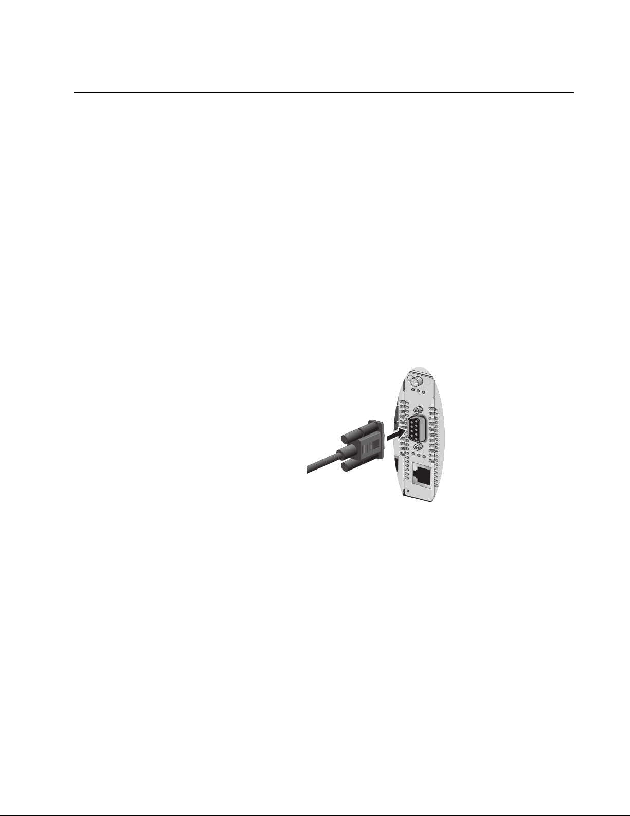
To start a local management session, perform the following procedure:
1. Connect one end of a straight-through RS-232 cable with a DB-9
connector to the RS-232 Terminal Port on the AT-CV5M01 CPM card,
as shown in Figure 1.
530
Figure 1. Connecting RS-232 Cable to AT-CV5M01 CPM’s Console Port
2. Connect the other end of the cable to an RS-232 port on a terminal or
PC with a terminal emulator program.
3. Configure the terminal or terminal emulation program as follows:
Bits per second: 1200 bps to 115200bps (default 115200)
(see Note below)
Data bits: 8
Parity: None
Stop bits: 1
Flow control: None
21
Page 22

Chapter 2: Starting a Local or Telnet Management Session
Note
The Converteon™ chassis has an auto-detect feature on the serial
port that automatically determines the speed of the local terminal.
You activate this feature by pressing the Return or Enter key twice
on your keyboard when you initially start the local interface or within
five seconds after powering on or resetting the chassis. The chassis
determines the speed of the terminal and automatically configures
the speed of the “console” port accordingly. The chassis uses a data
rate of 11520000 bits per second (bps). The chassis maintains the
terminal port speed until the system is again powered ON or reset.
Note
The default settings for the terminal interface are for a DEC VT100
or ANSI terminal, or an equivalent terminal emulator program. Once
you have started an management session, you can change some of
these values.
4. Press <Return> key twice.
5. When prompted, enter a username and password.
To configure the chassis settings, enter “manager” as the
username. The default password for manager access is “friend”.
To just view the settings, enter “operator” as the username. The
default password for operator access is “operator”.
Usernames and passwords are case-sensitive.
For information on these two access levels, refer to “Management
Access Levels” on page 31.
For instructions on how to change a password, refer to “Manager and
Operator Passwords” on page 28.
After logging on, the Main Menu, shown in Figure 2, is displayed.
Allied Telesyn AT-CV5M01 Management Module Software V1.2.0
CV-5000 Chassis
Main Menu
Module Status and Configuration
Administration
System Configuration
Remote Module Status and Configuration
Quit
Figure 2. Main Menu
22
Page 23

AT-S70 Management Software User’s Guide
To make a selection, refer to “Using the Terminal Interface” on
page 20.
Press <Esc> or select the “Return to ...” option at the bottom of the
menu, to save the settings and return to the previous menu.
Quitting from a
Local
Management
Session
To end a local management session, return to the Main Menu and type Q
for Quit.
You should always exit from a management session when you are finished
managing a chassis. This can prevent unauthorized individuals from
making changes to the configuration of a chassis would you leave your
management workstation unattended.
Note
You cannot operate both a local management session and a Telnet
management session on the same chassis simultaneously. You
cannot have any number of Telnet sessions running if there is a local
session running.Failure to properly exit from a local or Telnet
management session may block future management sessions.
23
Page 24

Chapter 2: Starting a Local or Telnet Management Session
Telnet Management Session
You can use the Telnet application protocol from a workstation on your
network to manage a Converteon™ chassis. This type of management
session is referred to as remote management session because you do not
have to be physically close to the chassis to start the session, such as with
a local management session. Any workstation on your network that has
the application protocol can be used to manage the chassis.
In terms of functionality, there are almost no differences between
managing a chassis locally through the RS-232 terminal port and remotely
with the Telnet application protocol. You see the same menu selections
and have nearly the same management capabilities.
If the Converteon™ chassis is in a TCP/IP environment, remote
management is possible only after the chassis has been assigned an IP
address and subnet mask. Initially, this is accomplished by managing the
chassis locally through the RS-232 port.
Starting a Telnet
Management
Session
To start a Telnet management session, specify the IP address of the
chassis in the Telnet application protocol and enter a username and
password when prompted.
To configure a chassis settings, enter “manager” as the user name. The
default password for manager access is “friend”. To just view the settings,
enter “operator” as the username. The default password for operator
access is “operator”. User names and passwords are case sensitive. For
information on the two access levels, refer to “Management Access
Levels” on page 31.
The Main Menu of a Telnet management session is the same menu that
you see in a local management session, shown in Figure 2 on page 22.
Nearly all the functions from a local management session are available to
you from a Telnet management session. The menus also function the
same as with the local management session. To make a selection, refer to
“Using the Terminal Interface” on page 20.
Note
You can run only one Telnet management session on a
Converteon™ chassis at a time. Additionally, you cannot run both a
Telnet management session and a local management session on
the same chassis at the same time.
Note
You can have up to 10 sessions (1-manager and 9-operator)
running simultaneously.
24
Page 25

AT-S70 Management Software User’s Guide
Quitting from a
Telnet
Management
Session
To end a Telnet management session, return to the Main Menu and type Q
for Quit.
You should always be sure to exit from a management session when you
are finished managing a Converteon™ chassis. This can prevent
unauthorized changes to a chassis’ configuration should you leave your
workstation unattended.
Note
You cannot operate both a local management session and a Telnet
management session on the same chassis simultaneously. You
cannot have any number of Telnet sessions running if there is a local
session running.Failure to properly exit from a local or Telnet
management session may block future management sessions.
25
Page 26

Chapter 2: Starting a Local or Telnet Management Session
Saving Your Parameter Changes
When changes are made to the chassis or to any of the line cards, the
changes (except for the system date and time) are immediately activated
and permanently saved onto the AT-CV5M01 CPM card as soon as you
enter them. These changes are retained by the CPM card even when the
chassis is reset or power cycled.
Saving the
Configuration
File Before
Replacing an
AT-CV5M01
CPM Card
When an AT-CV5M01 CPM is replaced, all the parameter settings saved
on the CPM card are gone. Therefore, to keep the current parameter
settings, make sure to upload the configuration file onto your computer or
laptop before replacing the AT-CV5M01 CPM card. Once a new
AT-CV5M01 CPM card is installed, you can then download the
configuration file back onto the new CPM card.
For instructions how to upload and download a configuration file, refer to
Chapter 9, “File Downloads and Uploads” on page 112.
26
Page 27

Chapter 3
AT-S70 Management Security Features
This chapter describes the security features in the AT-S70 software that
can help prevent unauthorized individuals from changing the parameter
settings of a Converteon™ chassis.
This chapter contains the following sessions:
“Manager and Operator Passwords” on page 28
“Console Timeout” on page 30
“Management Access Levels” on page 31
27
Page 28

Chapter 3: AT-S70 Management Security Features
Manager and Operator Passwords
The AT-S70 management software has two levels of management
access: Manager and Operator. The Manager account allows you to
configure all parameters of a Converteon™ chassis, while the Operator
account only allows you to view the parameter settings. The default login
name for Manager access is “manager” and the password is “friend”. The
default login name and password for Operator access are both “operator”.
Login names and passwords are case-sensitive.
Note
Once the password has been changed and is forgotten, you must
call Technical Support to have it reset back to the default password.
For Technical Support contact info, refer to “Contacting Allied
Telesyn” on page 12.
Configuring the
Management
Passwords
To prevent unauthorized access to the management program, you can
assign a password to the program. Any person who starts the interface will
be required to enter the password, regardless of how they access the
program (i.e., RS-232 port, Telnet, or SNMP management program). For
detailed information on the management program, refer to Chapter 1,
”Overview” on page 14.
To change the Manager or Operator password, perform the following
procedure:
1. From the Main Menu, select System Configuration.
The System Configuration Menu, shown in Figure 3 is displayed.
System Configuration Menu
System Name: Converteon
System Date (mm/dd/yy) 00/00/00
System Time (hh:mm:ss) 00:16:32
Omega Options
IP Parameters
Terminal Configuration
Temperature Threshold Configuration
Return to Main Menu...
Figure 3. System Configuration Menu
28
Page 29

AT-S70 Management Software User’s Guide
2. From the System Configuration Menu, select Omega Options.
The Omega Options Menu, shown in Figure 4, is displayed.
Omega Options Menu
System Name:
Manager Password: *****************
Operator Password: *****************
Timeout: 10
> Local Omega Enabled
Disable Local Omega
> Remote Omega Enabled
No Remote Omega
Return to System Configuration Menu...
Figure 4. Omega Options Menu
3. From the Omega Options Menu, select the Manager Password to
change the Manager password or Operator Password to change the
Operator password.
4. Enter the password. When entered, the password is displayed as a
series of asterisks. To delete the current password but not assign a
new password, enter a space in the Manager Password field.
The default password for Manager access is “friend”.
The default password for Operator access is “operator”
The password is case-sensitive and can be from 0 to 20 alphanumeric
characters.
Note
The password can consist of the letters A to Z in uppercase and
lowercase, as well as the numbers 1 to 9. Do not use special
characters, such as a space, asterisk (*), or exclamation point (!).
5. Press <Return>.
The new password is automatically saved by the management
software. You will be required to enter the password the next time you
start a management session.
6. Press <Esc> or select the “Return to ...” option at the bottom of the
menu, to save the settings and return to the previous menu.
29
Page 30

Chapter 3: AT-S70 Management Security Features
Console Timeout
This parameter causes the management software to automatically end a
management session if it does not detect any activity from the local or
remote management workstation after the specified period of time. This
security feature can prevent unauthorized individuals from using your
management workstation should you step away from your system while
configuring a chassis. The default console time value is 10 minutes.
Setting a Console
Timeout Value
To set a timeout value so that the program will end the session if there has
been no management activity after the timeout value has expired, perform
the following procedure:
1. From the Main Menu, select System Configuration.
The System Configuration Menu, shown in Figure 3 on page 28, is
displayed.
2. From the System Configuration Menu, select Omega Options.
The Omega Options Menu, shown in Figure 4 on page 29, is
displayed.
3. To configure the console timer, select Timeout and enter a value from
0 (zero) to 32,767 (in minutes). The default console time value is 10
minutes.
Note
Entering a value of 0 means there is no timeout. The Omega
interface will not automatically end any session. A session is ended
only if you end the session yourself. If you enter 0, you must always
properly quit after a management session in order not to block
subsequent remote sessions and software downloads to the
chassis.
A new console timer value takes affect the next time your start a local
or remote management session.
4. Press <Return>.
The new timeout value is now active.
5. Press <Esc> or select the “Return to ...” option at the bottom of the
menu, to save the settings and return to the previous menu.
30
Page 31

Management Access Levels
There are two levels of management access in the AT-S70 management
software: Manager and Operator. When you log in as a Manager, you can
view and configure all operating parameters. When you log in as an
Operator, you can only view the operating parameters; you cannot change
any values.
You log in as a manager or an operator when you enter the appropriate
username and password when you start an AT-S70 management session.
To log in as a manager, type “manager” as the login name. The default
password is “friend”. The username for operator is “operator” and the
default password is also “operator”. The usernames and passwords are
case sensitive.
Note
Once the password has been changed and is forgotten, you must
call Technical Support to have it reset back to the default password.
For Technical Support contact info, refer to “Contacting Allied
Telesyn” on page 12.
AT-S70 Management Software User’s Guide
Accessing the
Management
Software
Configuring
Management
Access
There are three ways to access the management software on a
Converteon™ chassis. These methods are referred to in this guide as
management sessions. They are:
Local management session, as described in “Local Management
Session” on page 16.
Telnet management session, as described in “Telnet Management
Session” on page 17.
SNMP management session, as described in “SNMP Management
Session” on page 18.
You can configure one or more of these methods to enhance the security
of the chassis by preventing unauthorized changes to the module and port
configurations.
To enable or disable a management access method, perform the following
procedure:
1. From the Main Menu, select System Configuration.
The System Configuration Menu, shown in Figure 3 on page 28, is
displayed.
31
Page 32

Chapter 3: AT-S70 Management Security Features
2. From the System Configuration Menu, select Omega Options.
The Omega Options Menu, shown in Figure 4 on page 29, is
displayed.
3. Adjust the settings as required.
The management access methods are described below:
> Local Omega Enabled
Disabled Local Omega
These two selections allow you to control whether the Omega
interface can be accessed by connecting a terminal or PC to the
RS-232 port on the management module. This is referred to as
accessing the program locally. The default for this access method is
enabled.
> Remote Omega Enabled
No Remote Omega
Accessing Omega remotely is accomplished with the Telnet program
or an SNMP management program, such as HP Openview. The
default for this access method is enabled.
4. Press <Esc> or select the “Return to ...” option at the bottom of the
menu, to save the settings and return to the previous menu.
32
Page 33

Chapter 4
Basic Parameters
This chapter contains a variety of information and procedures. The is a
discussion on when to assign an IP address to a chassis and the different
ways to it. There are also procedures for resetting the chassis, activating
the chassis default settings, and more.
This chapter contains the following sections:
“When Does a Converteon™ Chassis Need an IP Address?” on
page 34
“Configuring Basic Chassis Parameters” on page 35
“Configuring the Chassis Temperature Threshold” on page 42
“Pinging a Remote System” on page 43
“Resetting and Restarting the System” on page 45
“Setting the RS-232 Terminal Baud Rate” on page 47
33
Page 34

Chapter 4: Basic Parameters
When Does a Converteon™ Chassis Need an IP Address?
One of the tasks to building or expanding a network is deciding which of
the managed chassis need a unique IP address. In the past, the rule was
that a managed chassis needed an IP address if you wanted to manage it
remotely, such as with the Telnet application protocol or a web browser.
However, if a network contained a lot of managed chassis, having to
assign each one an IP address was often cumbersome and time
consuming. It was also often difficult keeping track of all the IP addresses.
When you assign a chassis an IP address, you must also assign it a
subnet mask. The chassis uses the subnet mask to determine which
portion of an IP address represents the network address and which the
node address. You must also assign the chassis a gateway address if the
chassis and a remote management workstation are separated by a router.
This gateway address is the IP address of the router through which the
chassis and remote management workstation will communicate.
If you do not plan to remotely manage any of the Converteon™ Series
chassis in your network, you do not need to assign any of them an IP
address. The chassis can operate without an IP address and you will still
be able to manage them completely using local management sessions.
Assigning an IP
Address
Once you have decided which, if any, chassis on your network need an IP
address, you have to access the AT-S70 software on the chassis and
assign the addresses. There are actually two ways in which a chassis can
obtain an IP address.
The first method is for you to assign the IP configuration information
manually This procedure is explained in “Configuring the IP Address,
Subnet Mask, and Default Gateway” on page 38.
The second method is for you to activate the DHCP service on the
chassis and have the chassis automatically download its IP
configuration information from a DHCP server on your network. This
procedure is explained in “Enabling and Disabling DHCP” on page 40.
Note
Initially assigning an IP address to a chassis or activating DHCP can
only be done through a local management session.
34
Page 35

Configuring Basic Chassis Parameters
The AT-S70 management software provides options to configure some
basic parameters on the chassis.
This section contains the following procedures:
“Assigning an IP Address” on page 34
“Naming the System” on page 35
“Setting the System Date and Time” on page 36
“Configuring the System Location and Contact Information” on page 37
“Configuring the IP Address, Subnet Mask, and Default Gateway” on
page 38
“Configuring the Manager IP Addresses” on page 39
“Configuring SNMP Community Strings” on page 39
“Enabling and Disabling DHCP” on page 40
AT-S70 Management Software User’s Guide
Naming the
System
To set the chassis name, perform the following procedure:
1. From the Main Menu, select System Configuration.
The System Configuration Menu, shown in Figure 5, is displayed.
System Configuration Menu
System Name: Converteon
System Date (mm/dd/yy) 00/00/00
System Time (hh:mm:ss) 00:16:32
Omega Options
IP Parameters
Terminal Configuration
Temperature Threshold Configuration
Return to Main Menu...
Figure 5. System Configuration Menu
35
Page 36

Chapter 4: Basic Parameters
2. From the System Configuration Menu, select the System Name field
and enter a unique name for the chassis.
The name can be up to 40 characters, including spaces and special
characters. If the system already has a name that you want to delete
without entering a new name, press the space bar once.
3. Press <Esc> or select the “Return to ...” option at the bottom of the
menu, to save the settings and return to the previous menu.
Note
Once the system name is entered and approved, it will be displayed
at the tope of every AT-S70 menu.
Setting the
System Date and
Time
Setting the system date and time is important if you configured the chassis
to send traps to your management workstations. If the time is not set,
traps do not contain the correct date and time. Therefore, it becomes
difficult for you to determine when the events represented by the traps
occurred.
One way to set the system date and time is manually setting it using the
AT-S70 software menu interface. When you set the date and time
manually, the chassis loses the values when it is reset or power cycled.
Therefore, you must reset the values whenever you reset the chassis.
To set the system’s date and time, perform the following procedure:
1. From the Main Menu, select System Configuration.
The System Configuration Menu, shown in Figure 5 on page 35, is
displayed.
2. Adjust the following parameters as necessary:
System Date(mm/dd/yy)
Enter a date for the system in the “mm/dd/yy”. Use two numbers to
specify for the day, month, and year. Separate the values with slashes.
Select the System Time(hh:mm:ss)
Enter the new system real time in the “hh:mm:ss” format. Use two
numbers to specify for the hours, minutes, and seconds. Separate the
values with colons.
Note
If the AT-CV5M01 CPM card is reset or power cycled, the system
and time settings will be lost. You will need to re-enter the date and
time information.
3. Press <Esc> or select the “Return to ...” option at the bottom of the
menu, to save the settings and return to the previous menu.
36
Page 37

AT-S70 Management Software User’s Guide
Configuring the
System Location
and Contact
Information
To set the system’s location and contact information, perform the following
procedure:
1. From the Main Menu, select System Configuration.
The System Configuration Menu, shown in Figure 5 on page 35, is
displayed.
2. From the System Configuration Menu, select IP Parameters.
The IP Parameters Menu, shown in Figure 6, is displayed.
IP Parameters Menu
Converteon
Ip address: 10.0.0.1
Subnet mask: 255.255.252.0
Gateway address: 0.0.0.0
Manager address: 0.0.0.0
Manager address: 0.0.0.0
Manager address: 0.0.0.0
Manager address: 0.0.0.0
Get community string: public
Set community string: private
Trap community string: public
Location: California USA
Contact: Allied Telesyn
Disable DHCP
> Enable DHCP
Return to System Configuration Menu...
Figure 6. IP Parameters Menu
3. Adjust the following parameters as necessary:
Location
The location can be up to 20 alphanumeric characters, including
spaces and special characters. If the system already has a location
that you want to delete without entering a new location, press the
space bar once.
Contact
The contact information includes the name, phone number, and other
information that identifies the person responsible for managing the
system. The contact information can be up to 20 alphanumeric
characters, including spaces and special characters. If the system
37
Page 38

Chapter 4: Basic Parameters
already has the contact information that you want to delete without
entering new information, press the space bar once.
4. Press <Esc> or select the “Return to ...” option at the bottom of the
menu, to save the settings and return to the previous menu.
Configuring the
IP Address,
Subnet Mask, and
Default Gateway
The procedure in this section explains how to manually assign an IP
address, subnet mask, and gateway address to the chassis from a local or
Telnet management session. (If you want the chassis to obtain its IP
configuration from a DHCP server on your network, go to the procedure
“Enabling and Disabling DHCP” on page 40.)
To configure parameters for managing the chassis remotely, perform the
following procedure:
1. From the Main Menu, select System Configuration.
The System Configuration Menu, shown in Figure 5 on page 35, is
displayed.
2. From the System Configuration Menu, select IP Parameters.
The IP Parameters Menu, shown in Figure 6 on page 37, is displayed.
3. Make the necessary changes to the following parameters.
Ip address
This parameter specifies the IP address of the chassis. You must
assign a chassis an IP address so it can be managed remotely using
Telnet or an SNMP application. In addition, if the management
workstation is separated from the chassis by a router, you must also
provide a gateway address, which is the IP address of a router through
which the chassis can communicate with the remote management
workstation. The IP address must be entered in the format:
xxx.xxx.xxx.xxx. The default value is 10.0.0.1.
Subnet mask
This parameter specifies the subnet mask for the chassis. You must
specify a subnet mask to manage the chassis remotely. The mask
address must be entered in the format: xxx.xxx.xxx.xxx. The default
value is 255.255.252.0.
Gateway address
This parameter specifies the default router’s IP address. This address
is required if you intend to remotely manage the chassis from a
management workstation that is separated from the chassis by a
router. The gateway address must be entered in the format:
xxx.xxx.xxx.xxx. The default value is 0.0.0.0.
4. Press <Esc> or select the “Return to ...” option at the bottom of the
menu, to save the settings and return to the previous menu.
38
Page 39

AT-S70 Management Software User’s Guide
Configuring the
Manager IP
Addresses
You can specify up to four network management workstations that will
receive SNMP traps from the system.
To configure the management IP addresses, perform the following
procedure:
1. From the Main Menu, select System Configuration.
The System Configuration Menu, shown in Figure 5 on page 35, is
displayed.
2. From the System Configuration Menu, select IP Parameters.
The IP Parameters Menu, shown in Figure 6 on page 37, is displayed.
3. Adjust the following parameters as necessary:
Manager address(es)
This parameter specifies up to four IP addresses of network
management workstations that will receive SNMP traps from the
chassis. This is optional.
4. Press <Esc> or select the “Return to ...” option at the bottom of the
menu, to save the settings and return to the previous menu.
Configuring
SNMP
Community
Strings
To configure the SNMP community strings, perform the following
procedure:
Note
SNMP access is disabled by default. To enable SNMP access, refer
to “Configuring Management Access” on page 31.
1. From the Main Menu, select System Configuration.
The System Configuration Menu, shown in Figure 5 on page 35, is
displayed.
2. From the System Configuration Menu, select IP Parameters.
The IP Parameters Menu, shown in Figure 6 on page 37, is displayed.
3. Adjust the following parameters as necessary.
Get community string
The default setting for this string is “public.”
Set community string
The default setting for this string is “private.”
Trap community string
The default setting for this string is “public.”
39
Page 40

Chapter 4: Basic Parameters
Use these parameters to set the SNMP community strings on the
chassis. A community string can be up to thirteen characters.
Community strings are case sensitive and can contain spaces and
special characters, such as an exclamation point (!). Changes to the
SNMP parameters are immediately activated on the chassis.
Note
For a list of actions that generate SNMP traps, refer to “SNMP
Traps” on page 54.
4. Press <Esc> or select the “Return to ...” option at the bottom of the
menu, to save the settings and return to the previous menu.
Enabling and
Disabling DHCP
The DHCP application protocol was developed to simplify network
management. It is used to automatically assign IP configuration
information to the devices on your network, such as an IP address, subnet
mask, and a default gateway address.
Naturally, for this to work there must be a DHCP server residing on your
network and you must configure the service by entering in the MAC
address of the chassis.
DHCP services typically allow you to specify how the IP address is to be
assigned to the chassis. The choices are static and dynamic. If you
choose static, the server always assign the same IP address to the
chassis when the chassis is reset or powered ON. This is the preferred
configuration. Because the DHCP services always assign the same IP
address to a chassis, you will always know which IP address to use when
you need to remotely manage a particular chassis.
If you choose dynamic, the DHCP server assigns any unused IP address
that it has not already assigned to another device. This means that a
chassis might have a different IP address each time you reset or power
cycle the device, making it difficult for you to remotely manage the unit.
The default is disabled.
Note
Enabling DHCP overrides any IP configuration settings that you
manually assigned.
Note
The BOOTP, another protocol that performs an identical function, is
not available on the Converteon™ chassis.
40
Page 41

AT-S70 Management Software User’s Guide
To enable or disable the DHCP client software, perform the following
procedure:
1. From the Main Menu, select System Configuration.
The System Configuration Menu, shown in Figure 5 on page 35, is
displayed.
2. From the System Configuration Menu, select IP Parameters.
The IP Parameters Menu, shown in Figure 6 on page 37, is displayed.
3. From the IP Parameters Menu, select one of the following parameters:
Disable DHCP
Disables DHCP services on the chassis.
> Enable DHCP
Enables DHCP services on the chassis. If you enabled DHCP, you
must reset the chassis in order for the internal management module to
start issuing DHCP requests to obtain its IP configuration. The default
is enabled.
The Converteon™ chassis issues up to three requests for its IP
configuration from the DHCP server. If the DHCP server does not
respond, the chassis uses the assigned IP address, if one was
manually assigned.
4. Press <Esc> or select the “Return to ...” option at the bottom of the
menu, to save the settings and return to the previous menu.
Note
If you enable the DHCP client software, the chassis immediately
begins to query the network for a DHCP server. The chassis
continues to query the network for its IP configuration until it
receives a response.
Any static IP address, subnet mask, and gateway address assigned
to the chassis are deleted from the Administration menu and
replaced with the values the chassis receives from DHCP server. if
you later disable DHCP, these values are returned to their default
settings. For the default settings, refer to Appendix A, “AT-S70
Default Settings” on page 131.
41
Page 42

Chapter 4: Basic Parameters
Configuring the Chassis Temperature Threshold
You can set a maximum temperature threshold for the chassis. Whenever
a temperature threshold is exceeded, the chassis sends a trap to the
management workstations.
To set the chassis temperature threshold, perform the procedure:
1. From the Main Menu, select System Configuration.
The System Configuration Menu, shown in Figure 5 on page 35, is
displayed.
2. From the System Configuration Menu, select Temperature Threshold
Configuration.
The Temperature Threshold Configuration Menu, shown in Figure 7, is
displayed.
Temperature Threshold Configuration Menu
Converteon
Maximum Temperature Threshold: 60
Return to System Configuration Menu ...
Figure 7. Temperature Threshold Configuration Menu
3. In the Maximum Temperature Threshold, the currently set
temperature is displayed in Celsius (° C). Enter a number for the
maximum temperature threshold. The highest possible maximum
temperature is 75° C.
4. Press <Esc> or select the “Return to ...” option at the bottom of the
menu, to save the settings and return to the previous menu.
42
Page 43

Pinging a Remote System
You can instruct the chassis to ping a remote device on your network. This
procedure is useful in determining whether a valid link exists between the
chassis and another device. The chassis sends an Internet Control
Message Protocol (ICMP) echo request to the end node. If the end node is
operating and receives the request, it sends a reply to the chassis.
To instruct the chassis to ping a network device, perform the following
procedure:
1. From the Main Menu, select Administration.
The Administration Menu, shown in Figure 8, is displayed.
Image Download Through TFTP
Image Download Through XMODEM
LineCard Image Download Through XMODEM
LineCard Image Download Through TFTP
Upload Configuration Through TFTP
Download Configuration Through TFTP
Ping a remote system
Syslog Server Address: Null (not configured)
Syslog Facility Code: 1
Event Log
Activity Monitor
> Start Log
Stop Log
AT-S70 Management Software User’s Guide
Administration Menu
Converteon
Diagnostics
CPM Switch Over
Reset Chassis and Restart Line Cards
Return to Main Menu...
Figure 8. Administration Menu
2. From the Administration Menu, select Ping a remote system.
43
Page 44

Chapter 4: Basic Parameters
The Ping window, shown in Figure 9, is displayed.
Converteon
Please enter Station IP Address to ping:
->
Figure 9. Ping Window
3. Enter the Station IP Address of the end-node you want the chassis to
ping.
4. Press <Return>.
The Omega interface activates the Activity Monitor window. This
window reports the results of the Ping command.
A ping command performed from a local or remote Omega session
continues until you press any key to stop it.
5. Press <Esc> or select the “Return to ...” option at the bottom of the
menu, to save the settings and return to the previous menu.
44
Page 45

Resetting and Restarting the System
When you reset a system, the system is also restarted. Resetting and
restarting the system is a way to refresh all the statistics displays or
overcome system errors. This process does no affect any system settings
or return the system to its default values. However, it does terminate your
management session and you must log in again after the reset is
complete.
Note
If DHCP is enabled, then the IP address of the Converteon™
chassis MAY change after a rest or power cycle. For more
information on how to enable DHCP, refer to “Enabling and
Disabling DHCP” on page 40.
To reset a chassis, perform the following procedure:
1. From the Main Menu, select Administration.
AT-S70 Management Software User’s Guide
The Administration Menu, shown in Figure 8 on page 43, is displayed.
2. From the Administration Menu, select Reset Chassis and Restart
Line Cards.
The Reset Chassis window, shown in Figure 10, is displayed.
Converteon
Do reset chassis now? (Yes or No):
Yes
>No
Return to Administration Menu...
Figure 10. Reset Chassis Window
3. From the Reset Chassis window, select Yes to reset the system or No
to cancel the command.
Note
Resetting the chassis also resets the line cards; therefore the traffic
stops momentarily during the reset.
45
Page 46

Chapter 4: Basic Parameters
If Yes is selected, the prompt, shown in Figure 11, is displayed.
Converteon
The chassis will reset when FLASH writes complete.
Figure 11. Resetting Chassis Confirmation Window
It takes a few seconds to reset the chassis. Once done, it returns to the
Administration menu. The changes made are now saved to the FLASH
PROM.
4. To resume managing the chassis, you must reestablish your
management session by logging in again.
46
Page 47

Setting the RS-232 Terminal Baud Rate
The default settings for the RS-232 port are:
Bits per second: 1200 bps to 115200bps
Data bits: 8
Parity: None
Stop bits: 1
Flow control: None
To set the RS-232 port to a different baud rate, perform the following
procedure:
1. From the Main Menu, select System Configuration.
The System Configuration Menu, shown in Figure 5 on page 35, is
displayed.
AT-S70 Management Software User’s Guide
2. From the System Configuration Menu, select Terminal
Configuration.
The Terminal Configuration Menu, shown in Figure 12, is displayed.
Terminal Configuration Menu
Converteon
Data rate (baud rate) ...
Return to System Configuration Menu...
Figure 12. Terminal Configuration Menu
3. From the Terminal Configuration Menu, select Data rate (baud rate).
47
Page 48

Chapter 4: Basic Parameters
The Terminal Data Rate Menu, shown in Figure 13, is displayed listing
the baud rates.
Terminal Data Rate Menu
Converteon
> 115200 bps
57600 bps
19200 bps
9600 bps
4800 bps
2400 bps
Return to Terminal Configuration Menu...
Figure 13. Terminal Data Rate Menu
4. From the Terminal Data Rate Menu, select the baud rate you want.
Possible baud rates are:
115200 bps (default)
57600 bps
19200 bps
9600 bps
4800 bps
2400 bps
5. Press <Esc> or select the “Return to ...” option at the bottom of the
menu, to save the settings and return to the previous menu.
Changes to the baud rate take effect the next time you start a local
management session.
48
Page 49

Chapter 5
Monitoring System Performance
This chapter describes the features in the AT-S70 for monitoring the
performance of the Converteon™ chassis.
This chapter contains the following sections:
“Displaying System Status Information” on page 50
“Displaying Remote Module Status and Configuration Information” on
page 52
“Using the System Activity Monitor” on page 54
“Using the System Diagnostics” on page 57
“Displaying Line Card Image Version” on page 60
“Displaying Line Card Information” on page 62
“Displaying SFP Module Information” on page 64
49
Page 50

Chapter 5: Monitoring System Performance
Displaying System Status Information
The AT-S70 management software provides comprehensive status
information about the operation of the chassis and its components,
including detailed information about the line cards.
To view chassis status information, perform the following procedure:
1. From the Main Menu, select Module Status and Configuration.
The Module Status and Configuration Menu, shown in Figure 14, is
displayed.
Module Status and Configuration
Converteon
Module Status Link(A) Link(B) OpMode
1: AT-CV5M01 On Online/100
2: AT-CM202 On Online/100 Offline OAM Visible
3: AT-CM202 On Online/100 Offline OAM Visible
4: AT-CM202 On Online/100 Online/10 OAM Visible
5:(Not Inserted) -- -- -- -6: AT-CM212A/1 On Online/100 Online/100 Link Test
7: AT-CM212A/1 On Online/100 Offline Link Test
8: AT-CM212B/1 On Online/100 Online/100 SML
9: AT-CM212B/1 On Online/100 Online/100 SML
10:(Not Inserted) -- -- -- -11: AT-CV1KSS On Online/1000 Online/1000 Link Test
12: AT-CV1KSS On Online/1000 Online/1000 Link Test
13: AT-CV1KSS On Online/1000 Offline Link Test
14: AT-CV1KSS On Online/1000 Online/1000 Link Test
15:(Not Inserted) -- -- -- -16: AT-CV102 On Online/100 Online/1000 Link Test
More ...
Return to Main Menu ...
Figure 14. Module Status and Configuration Menu (1/2)
50
Page 51

AT-S70 Management Software User’s Guide
2. In the Module Status and Configuration Menu, click More ... to display
the remainder of the modules and line cards in the chassis, as shown
in Figure 15.
Module Status and Configuration
Converteon
Module Status Link(A) Link(B) OpMode
17: AT-CM202 On Online/100 Offline OAM Visible
18: AT-CM202 On Online/100 Online/100 Link Test
19: LED On -- -20:(Not Inserted) -- -- -21: RPSA On
22: RPSB On
More ...
Return to Main Menu ...
Figure 15. Module Status and Configuration Menu - 2/2
The Module Status and Configuration Menu displays basic information on
all the components currently installed in the chassis, including:
Line cards or CPM card (slots 1 through 18)
LED interface card (slot 19)
Rear expansion slot (slot 20)
Primary and redundant power supplies (slots 21 and 22)
The basic information displayed on the installed component is:
Module
Displays the name of the module or line card and its slot number.
Status
Indicates the status of the module or line card.
Link (A) and Link (B)
Indicates whether there are any active connections between a port and the
device connected to the port. Online indicates that there is a link while
Offline indicates that there is no link.
More...
Scrolls the screen to show the remaining modules.
3. Press <Esc> or select the “Return to ...” option at the bottom of the
menu, to save the settings and return to the previous menu.
51
Page 52

Chapter 5: Monitoring System Performance
Displaying Remote Module Status and Configuration Information
The AT-S70 management software provides comprehensive status
information about the operation of the remote module and its components.
Note
ATI Proprietary Remote Management – This feature only supports
the AT-CM Series line cards (AT-CM202, AT-CM212, etc.), and not
the AT-CV Series line cards (AT-CV10x, AT-CV1KSS, etc.) For
Remote Module Status and Configuration to work, the OAM Visible
Mode (operating mode) must be turned ON. This feature utilized and
extended the IEEE 802.3 ah (OAM) protocol standard.
To view remote module status information, perform the following
procedure:
1. From the Main Menu, select Remote Module Status and
Configuration.
The Remote Module Status and Configuration Menu, shown in
Figure 16, is displayed.
Remote Module Status and Configuration
Converteon
Remote Peer On Fiber Connection
Module Card Type Version Link Status (Port A)
1: AT-CV5M01 No Support No Support No Support
2: AT-CM202 -- -- -3: AT-CM202 AT-CM212A/1 V.1.2.0 Online
4: AT-CM202 -- -- -5:(Not Inserted) -- -- -6: AT-CM212A/1 -- -- -7: AT-CM212A/1 AT-CM202 V.1.2.0 Online
8: AT-CM212B/1 -- -- --
9: AT-CM212B/1 -- -- -10:(Not Inserted) -- -- -11: AT-CV1KSS No Support No Support No Support
12: AT-CV1KSS No Support No Support No Support
13: AT-CV1KSS No Support No Support No Support
14: AT-CV1KSS No Support No Support No Support
15:(Not Inserted) -- -- -16: AT-CV102 No Support No Support No Support
More ...
Return to Main Menu ...
Figure 16. Remote Module Status and Configuration Menu
52
Page 53

AT-S70 Management Software User’s Guide
2. In the Module Status and Configuration Menu, click More ... to display
the remainder of the modules and line cards in the chassis, as shown
in Figure 17.
Module Status and Configuration
Converteon
Module Card Type Version Link Status (Port A)
17: AT-CM202 AT-CM212A/1 V.1.2.0 Online
18: AT-CM202 AT-CM212B/1 V.1.2.0 Online
More ...
Return to Main Menu ...
Figure 17. Module Status and Configuration Menu - 2/2
The Remote Module Status and Configuration Menu displays the fiber
connection between the local chassis and the remote device, as described
below:
Note
This feature only supports the AT-CM Series line cards
(AT-CM202, AT-CM212, etc.), and not the AT-CV Series line cards
(AT-CV10x, AT-CV1KSS, etc.) Therefore, the AT-CV Series line
cards will be displayed as “No Support”.
Module
Displays the name of the module or line card and its slot number.
Card Type
Indicates the type of the remote module the line card is connected to.
Version
Indicates the version of the remote module the line card is connected to.
Link Status (A)
Indicates whether there are any active connections between the port on
the local line card and the remote module connected to it.
More...
Scrolls the screen to show the remaining modules.
3. Press <Esc> or select the “Return to ...” option at the bottom of the
menu, to save the settings and return to the previous menu.
53
Page 54

Chapter 5: Monitoring System Performance
Using the System Activity Monitor
The AT-S70 management software keeps a list of the chassis SNMP
events such as removal of a line card, loss of a data link, failure of a fan
module, etc. This list is called the activity log and you use the activity
monitor to display the log. The activity log contains only those events that
have occurred since you started the management session. Ending the
session purges the log.
SNMP Traps The SNMP traps provide information for status of chassis modules such
as line cards, fans, power supplies, as well as chassis temperature.
Activities that generate the SNMP traps are listed as follows:
Module inserted
Module removed
Port link online
Port link offline
Fan failure - fan one of tray one
Fan failure - fan two of tray one
Fan failure - fan one of tray two
Fan failure - fan two of tray two
Fan recovered - fan one of tray one
Fan recovered - fan two of tray one
Fan recovered - fan one of tray two
Fan recovered - fan two of tray two
12V power failure
5V power failure
3.3V power failure
12V power recovered
5V power recovered
3.3V power recovered
Power supply module inserted
Power supply module removed
Chassis Over-Temperature
Chassis Over-Temperature removed
Fan module inserted
Fan module removed
54
Page 55

AT-S70 Management Software User’s Guide
Starting and
Stopping the
Activity Log
To start or stop the activity log, perform the following procedure:
1. From the Main Menu, select Administration.
The Administration Menu, shown in Figure 18, is displayed.
Administration Menu
Converteon
Image Download Through TFTP
Image Download Through XMODEM
LineCard Image Download Through XMODEM
LineCard Image Download Through TFTP
Upload Configuration Through TFTP
Download Configuration Through TFTP
Ping a remote system
Syslog Server Address: Null (not configured)
Syslog Facility Code: 1
Event Log
Activity Monitor
> Start Log
Stop Log
Diagnostics
CPM Switch Over
Reset Chassis and Restart Line Cards
Displaying the
Activity Log
Return to Main Menu...
Figure 18. Administration Menu
2. From the Administration Menu, select Start Log to start the activity log
or Stop Log to stop the activity log.
The default is Start Log.
To view the activity log, perform the following procedure:
1. From the Main Menu, select Administration.
The Administration Menu, shown in Figure 18 on page 55, is
displayed.
2. From the Administration Menu, select Activity Monitor.
55
Page 56

Chapter 5: Monitoring System Performance
An example of the Activity Monitor window, shown in Figure 19, is
displayed.
Converteon
Activity Monitor
(hit Return to resume the previous menu)
00/00/00 00:00:23 Module #5 has been removed!
00/00/00 00:00:25 Module #5 has been Installed!
00/00/00 00:00:30 Module #10 has been removed!
00/00/00 00:00:33 Module #10 has been Installed!
00/00/00 00:00:34 Power Tray A has been Installed!
00/00/00 00:00:34 Power Tray B has been removed!
Figure 19. Activity Monitor Window Example
The activity monitor continues to display system activities until you
press Return to return to the previous menu and select Stop Log.
3. Press <Esc> or select the “Return to ...” option at the bottom of the
menu, to save the settings and return to the previous menu.
56
Page 57

Using the System Diagnostics
The AT-S70 management software provides an option to run diagnostic
self-tests on the chassis and line cards. The following section describes
how to run chassis diagnostics. Using this information helps you diagnose
performance problems with the chassis.
The diagnostic command displays the status of the following items:
Flash PROM
Serial interface
Power supply status
Optional power supply status (if installed)
Operational status, speed, temperature and power of the fan modules
A diagnostic test also displays the following:
AT-S70 Management Software User’s Guide
Management Software Image Version and Cycle Number
Line card MAC Address
Line card Serial Number
Converteon™ chassis model
Running and current times
To run the chassis diagnostics, perform the following procedure:
1. From the Main Menu, select Administration.
The Administration Menu, shown in Figure 18 on page 55, is
displayed.
2. From the Administration Menu, select Diagnostics.
57
Page 58

Chapter 5: Monitoring System Performance
3. From the Diagnostics Menu, select Chassis Diagnostics.
The Diagnostic Menu, shown in Figure 20, is displayed.
Diagnostics Menu
Converteon
Chassis Diagnostics
Line Card Image Version
Line Card Information
SFP Information
Return to Administration Menu...
Figure 20. Diagnostics Menu
The AT-S70 management software runs the diagnostics on the chassis
and displays the Chassis Diagnostics menu, as shown in Figure 21.
Chassis Diagnostics Menu
Converteon
Serial Number:
MAC Address FF:FF:FF:FF:FF:FF
CONVERTEON Chassis: CV-5000 Chassis Revision V1.2.0
Running 0 days, 1 hours, 10 minutes, 9 seconds
Current Time: 00/00/00 01:10:47
Diagnostic Results:
Flash PROM Good
Serial Interface Good
RPSA Good Fan Status Failed Fan Temperature: 37 C
Fan 3.3V Power: 3.2 V Fan 5V Power: 4.9 V Fan 12V Power: 0.0 V
Fan1 Speed: Off Fan2 Speed: Off
RPSB Failed Fan Status Failed Fan Temperature: 35 C
Fan 3.3V Power: 3.2 V Fan 5V Power: 4.9 V Fan 12V Power: 11.7 V
Fan1 Speed: Off Fan2 Speed: Off
Hit any key to continue ...
Figure 21. Chassis Diagnostics Menu
58
Page 59

AT-S70 Management Software User’s Guide
The information displayed on the Chassis Diagnostics Menu is for
viewing purposes only.
Note
The Flash PROM and Serial Interface test results are displayed as
Good or Failed. If the chassis does not have a optional power supply
installed, the results for “RPSB” is displayed as Failed.
The top portion of the Chassis Diagnostics menu contains the following
items of system information:
Serial Number
Indicates the serial number and hardware revision level of the system.
MAC Address
Indicates the MAC address of the chassis.
Converteon Chassis
Indicates the Converteon™ chassis model and revision
(i.e. AT-CV5000 Revision 1.0.0).
Running
Indicates the number of hours, minutes, and seconds that the chassis
has been running since it was last powered ON.
Current Time
Indicates the current time set on the chassis.
The lower portion of the Chassis Diagnostic menu contains diagnostic
information of the following items:
Flash PROM
Indicates the status of the Flash PROM and its current voltage.
Serial Interface
Indicates the status of the RS-232 port and its current voltage.
RPSA and RPSB
Indicates the status of the power supplies whether or not the power
supply is turned ON.
Fan1 and Fan2
Indicates the status of the fan modules, including the power voltage
they are using, the speed they are running, an their temperature.
4. Press <Esc> or hit any key to return to the previous menu.
59
Page 60

Chapter 5: Monitoring System Performance
Displaying Line Card Image Version
To view the latest image version of a line card, perform the following
procedure:
1. From the Main Menu, select Administration.
The Administration Menu, shown in Figure 18 on page 55, is
displayed.
2. From the Administration Menu, select Diagnostics.
The Diagnostic Menu, shown in Figure 20 on page 58, is displayed.
3. From the Diagnostics Menu, select Line Card Image Version.
The Line Card Module Software Image Version window, shown in
Figure 22, is displayed.
Line Card Module Software Image Version
Converteon
Module Version
1: AT-CV5M01 V1.2.0
2: AT-CM202 V1.2.0
3: AT-CM202 V1.2.0
4: AT-CM202 V1.2.0
5:(Not Inserted) - 6: AT-CM212A/1 V1.2.0
7: AT-CM212A/1 V1.2.0
8: AT-CM212B/1 V1.2.0
9: AT-CM212B/1 V1.2.0
10:(Not Inserted) -11: AT-CV1KSS V1.2.0
12: AT-CV1KSS V1.2.0
13: AT-CV1KSS V1.2.0
14: AT-CV1KSS V1.2.0
15:(Not Inserted) -16: AT-CV102 V1.2.0
17: AT-CV102 V1.2.0
18: AT-CV102 V1.2.0
Hit any key to continue ...
Figure 22. Line Card Module Software Image Version Window
60
Page 61

AT-S70 Management Software User’s Guide
The Line Card Module Software Image Version window contains the
following information:
Module
Displays the name of the module or line card and its slot number.
Version
Indicates the software version the line cards are using.
Cycle
Indicates the cycle release number of the software version the line
cards are using.
4. Press <Esc> or hit any key to continue.
61
Page 62

Chapter 5: Monitoring System Performance
Displaying Line Card Information
To view la line card information, perform the following procedure:
1. From the Main Menu, select Administration.
The Administration Menu, shown in Figure 18 on page 55, is
displayed.
2. From the Administration Menu, select Diagnostics.
The Diagnostic Menu, shown in Figure 20 on page 58, is displayed.
3. From the Diagnostics Menu, select Line Card Information.
The Line Card Module Information window, shown in Figure 23, is
displayed.
Line Card Module Information
Converteon
Module MAC Address Serial Number
1: AT-CV5M01 000C469A214B 7
2: AT-CM202 323032055148 SN # 32
3: AT-CM202 437032055272 SN # 43
4: AT-CM202 983032055331 4#21
5:(Not Inserted) -- -6: AT-CM212A/1 503032055515 6#38
7: AT-CM212A/1 323032055546 7#45
8: AT-CM212B/1 210C469A21DF 155
9: AT-CM212B/1 087C469A21E6 142
10:(Not Inserted) -- -11: AT-CV1KSS 078C435A21AA 321
12: AT-CV1KSS 000C469A21DF 4#36
13: AT-CV1KSS 017C469A07ST 243
14: AT-CV1KSS 850A869369QT 027
15:(Not Inserted) -- -16:AT-CM202 323032055611 SN # 49
17: AT-CM202 043032874335 SN # 53
18: AT-CM202 323032055702 SN # 67
Hit any key to continue ...
Figure 23. Line Card Module Information Window
62
Page 63

AT-S70 Management Software User’s Guide
The Line Card Module Information window contains the following
information:
Module
Displays the name of the module or line card and its slot number.
MAC Address
Indicates the MAC Address of the line cards.
Serial Number
Indicates the serial number of the line cards.
4. Press <Esc> or hit any key to continue.
63
Page 64

Chapter 5: Monitoring System Performance
Displaying SFP Module Information
To view la SFP module information, perform the following procedure:
1. From the Main Menu, select Administration.
The Administration Menu, shown in Figure 18 on page 55, is
displayed.
2. From the Administration Menu, select Diagnostics.
The Diagnostic Menu, shown in Figure 20 on page 58, is displayed.
3. From the Diagnostics Menu, select SFP Information.
The SFP Information window, shown in Figure 24, is displayed.
SFP Information
Converteon
Enter LineCard Slot Number: ->
Figure 24. SFP Information - Linecard Slot Prompt
4. Enter the slot number of the line card that houses the SFP module you
wish to gather information of.
The prompt, shown in Figure 25, is displayed.
SFP Information
Converteon
Enter LineCard Port [A or B]: ->
Figure 25. SFP Information - Linecard Port Prompt
5. Enter which SFP port on the line card you wish to gather information
of.
64
Page 65

AT-S70 Management Software User’s Guide
The SFP Information window, shown in Figure 26, is displayed, listing
the specifications of the selected SFP module.
SFP Information
Slot 4: Port A
Type of Serial Transceiver: 3 (Vendor Specific)
SONET Compliance Codes: 22
Gigabit Ethernet Compliance Codes: 2
Fiber Channel Link Length: 20
Fiber Channel Transmitter Type: 10
Fiber Channel Media Type: 1
Fiber Channel Speed: 15
Encoding: 5
Normal Baud Rate: 19 (2.5GHz)
9micro, Distance: 14
50micro, Distance: 0
60micro, Distance: 0
CU, Distance: 0
Transmit Disable: 1
Laser Fault: 1
Signal Detect (Logical 0) 0
Signal Detect (Logical 1) 1
Upper Baud Rate Margin (in %) 96
Lower Baud Rate Margin (in %) 8
Hit any key to continue ...
SFP Information Window (1/2)
SFP Information
Slot 4: Port A
Vendor name (OUI) LUMINENT
Vendor IEEE Company ID: 06b5
Vendor part number: SFP-2500-SR1
Vendor revision number: 0000
Vendor serial number: 369G12O986
Vendor date code: 030609
Vendor specific ID:
Hit any key to continue ...
Figure 26. SFP Information Window (2/2)
6. Press <Esc> or hit any key to continue.
65
Page 66

Chapter 6
Event Logs and Syslog Servers
This chapter describes how to view and clear the contents of the event
logs. The event logs that allow you to view chassis information. In addition,
it also discusses how to configure the syslog server address and facility
code. Sections in the chapter include:
“Event Log Overview” on page 67
“Working with the Event Log” on page 68
“Working with the Syslog Server” on page 71
“Setting Syslog Facility Code” on page 72
66
Page 67

Event Log Overview
A managed Converteon™ media chassis is a complex piece of computer
that includes both hardware and software. Multiple software features
operate simultaneously, interoperating with each other and processing
large amounts of network traffic. It is often difficult to determine exactly
what is happening when a chassis appears not to be operating normally,
or what happened when the problem occurred.
A network manager’s major task is to monitor the system functions and to
deal with problems as they arise. One method for doing this is to view the
event messages that are generated by the chassis and sent to the event
log. This events can provide vital information about system activity on a
Converteon™ chassis that help you identify and solve system problems.
The event log includes the following information:
The date of an event
The time of an event
AT-S70 Management Software User’s Guide
A message of the event
There are two ways that you can view a chassis’ event messages. The first
method is to view an event log. The second method is to have the chassis
send its events to a syslog server. The syslog server functions as a central
repository that stores events from many network devices simultaneously.
In order for a Converteon™ chassis to send its events to a syslog server,
you must define the syslog output. The syslog output includes the IP
address of the syslog server along with other information such as the
types of event messages you want the chassis to send to the syslog
server.
Note
The event logs, even when disabled, log all AT-S70 initialization
events that occur when the chassis is reset and power cycled. Any
chassis events that occur after the AT-S70 initialization are entered
into the logs only if you enable the event log feature. The default
setting for the event log feature is enabled.
67
Page 68

Chapter 6: Event Logs and Syslog Servers
Working with the Event Log
This section contains the following procedures:
“Displaying an Event Log” on page 68
“Clearing an Event Log” on page 70
Displaying an
Event Log
Each time that you want to view the event log, you must choose how and
what you want displayed. The event log settings are not saved.
To specify the type of events you want to display in the event log, perform
the following procedure:
1. From the Main Menu, select Administration.
The Administration Menu, shown in Figure 27, is displayed.
Administration Menu
Converteon
Image Download Through TFTP
Image Download Through XMODEM
LineCard Image Download Through XMODEM
LineCard Image Download Through TFTP
Upload Configuration Through TFTP
Download Configuration Through TFTP
Ping a remote system
Syslog Server Address: Null (not configured)
Syslog Facility Code: 1
Event Log
Activity Monitor
> Start Log
Stop Log
Diagnostics
CPM Switch Over
Reset Chassis and Restart Line Cards
Return to Main Menu...
Figure 27. Administration Menu
2. From the Administration Menu, select Event Log.
68
Page 69

AT-S70 Management Software User’s Guide
The Event Log Menu window is displayed, shown in Figure 28.
Event Log Menu
Converteon
Display Event Log
Clear Event Log
Return to Administration Menu ...
Figure 28. Event Log Menu
3. From the Event Log Menu, select Display Event Log.
An example of an event log, shown in Figure 29, is displayed.
Converteon
Event Log
Total Events: 8. Displaying: 1 to 8
Date Time Message
---------------------------------------------------------------------------
00/00/00 00:00:02: REPORT: Power Module 1 Inserted
00/00/00 00:00:02: REPORT: Power Module 2 Removed
00/00/00 00:00:02: REPORT: Fan Tray #1 has been removed!
00/00/00 00:00:02: REPORT: Fan Tray #2 has been removed!
00/00/00 00:00:02: REPORT: Power Module 1 Inserted
00/00/00 00:00:02: REPORT: Power Module 2 Removed
00/00/00 00:00:02: REPORT: Fan Tray #1 has been removed!
00/00/00 00:00:02: REPORT: Fan Tray #2 has been removed!
N - Next Page, P - Previous Page, F - First Page, L - Last Page, R - Return
Figure 29. Example of an Event Log
The events are displayed in a table. The columns in the table are
described below:
Date
The date the event occurred.
Time
The time the event occurred.
Message
The activity the event reported.
69
Page 70

Chapter 6: Event Logs and Syslog Servers
4. Type the following to scroll through the event log:
N - Next page
P - Previous page
F - First page
L - Last page
R - Return to the Event Log Menu
To clear the current event log, go to the next section “Clearing an
Event Log”.
Clearing an
Event Log
You can clear the event log to remove old events and start fresh. To clear
the event log, perform the following procedure:
1. From the Main Menu, select Administration.
The Administration Menu, shown in Figure 27 on page 68, is
displayed.
1. From the Administration Menu, select Event Log.
The Event Log Menu window is displayed, shown in Figure 28 on page
69.
2. From the Event Log Menu, select Clear Event Log.
The prompt, shown in Figure 30, is displayed.
Converteon
Please wait while the event log is cleared...
Figure 30. Clearing Event Log Prompt
3. When the clearing process is done, hit any key to continue.
70
Page 71

Working with the Syslog Server
AT-S70 Management Software User’s Guide
Configuring
Syslog Server
Address
To specify the IP address of the syslog server, perform the following
procedure:
1. From the Main Menu, select Administration.
The Administration Menu, shown in Figure 27 on page 68, is
displayed.
2. From the Administration Menu, select Syslog Server Address field
and enter the IP address of the syslog server.
3. Press <Return>.
The syslog server IP address is displayed.
71
Page 72

Chapter 6: Event Logs and Syslog Servers
Setting Syslog Facility Code
This feature adds a facility code to the entries when they are sent to the
syslog server. The facility level is a way for you to add a numerical code to
each entry to help you group entries on the syslog server according to the
module or system that produced them. This grouping helps you determine
which events belong to which device when a syslog server is collecting
events from several network devices. You can specify only one facility
code.
To specify the facility code of the syslog server, perform the following
procedure:
1. From the Main Menu, select Administration.
The Administration Menu, shown in Figure 27 on page 68, is
displayed.
2. From the Administration Menu, select Syslog Facility Code field and
enter the facility code of the syslog server.
There are two approaches to using this feature. The first is to use the
default code setting “0” which is based on the functional groupings
defined in the RFC 3164 standard. The numerical codes that are
applicable to the AT-S70 management software and its modules are
shown in Table 2.
Table 2. Syslog Facility Applicable RFC 3164 Numerical Codes
Numerical Code Facility
0 kernel messages
1 user-level messages
2 mail system
3 system daemons
4
security/authorization messages
1
5 messages generated internally by syslog
6 line printer subsystem
7 network news subsystem
8 UUCP subsystem
9
10
clock daemon
security/authorization messages
2
1
72
Page 73

AT-S70 Management Software User’s Guide
Table 2. Syslog Facility Applicable RFC 3164 Numerical Codes
11 FTP daemon
12 NTP subsystem
13
14
15
log audit
log alert
clock daemon
1
1
2
16 local use 0 (LOCAL0)
17 local use 1 (LOCAL1)
18 local use 2 (LOCAL2)
19 local use 3 (LOCAL3)
20 local use 4 (LOCAL4)
21 local use 5 (LOCAL5)
22 local use 6 (LOCAL6)
23 local use 7 (LOCAL7)
1 Various operating systems have been found to utilize Facilities 4, 10, 13 and
14 for security/authorization, audit, and alert messages which seem to be
similar.
2. Various operating systems have been found to utilize both Facilities 9 and 15
for clock (cron/at) messages.
For example, selecting LOCAL1 as the facility level assigns the
numerical code of 17 to all events sent by the chassis to the syslog
server.
3. Press <Return>.
The selected syslog facility code is displayed.
73
Page 74

Chapter 7
Working with Line Cards and Other Modules
This chapter contains the following procedures:
“Displaying Basic Line Card Information” on page 75
“Displaying Line Card Status Information” on page 77
“Configuring Line Card Settings” on page 79
“Displaying AT-CV5M01 CPM Card Status Information” on page 86
“Working with the Redundant AT-CV5M01 CPM Card” on page 88
74
Page 75

AT-S70 Management Software User’s Guide
Displaying Basic Line Card Information
To display the status of the modules and line cards in the Converteon™
chassis, perform the following procedure:
1. From the Main Menu, select Module Status and Configuration.
The Module Status and Configuration Menu, shown in Figure 31, is
displayed.
Module Status and Configuration
Converteon
Module Status Link(A) Link(B) OpMode
1: AT-CV5M01 On Online/100
2: AT-CM202 On Online/100 Offline OAM Visible
3: AT-CM202 On Online/100 Offline OAM Visible
4: AT-CM202 On Online/100 Online/10 OAM Visible
5:(Not Inserted) -- -- -- -6: AT-CM212A/1 On Online/100 Online/100 Link Test
7: AT-CM212A/1 On Online/100 Offline Link Test
8: AT-CM212B/1 On Online/100 Online/100 SML
9: AT-CM212B/1 On Online/100 Online/100 SML
10:(Not Inserted) -- -- -- -11: AT-CV1KSS On Online/1000 Online/1000 Link Test
12: AT-CV1KSS On Online/1000 Online/1000 Link Test
13: AT-CV1KSS On Online/1000 Offline Link Test
14: AT-CV1KSS On Online/1000 Online/1000 Link Test
15:(Not Inserted) -- -- -- -16: AT-CV102 On Online/100 Online/1000 Link Test
More ...
Return to Main Menu ...
The fields are defined below:
Module
Displays the name of the module or line card and its slot number.
Status
Indicates the current status of the line card, whether there is no line
card inserted (--) or the correct line card is inserted in the slot and the
power is ON.
Figure 31. Module Status and Configuration Menu
75
Page 76

Chapter 7: Working with Line Cards and Other Modules
Link (A) and Link (B)
Indicates whether there are any active connections between a port
and the device connected to the port. Online indicates that there is a
link while Offline indicates that there is no link.
OpMode
Indicates the operating mode status configured on the line cards.
Possible values are:
Smart Missing Link Mode (SML)
Missing Link Mode (ML)
OAM BYPASS Mode
OAM Visible Mode
Link Test Mode
More...
Scrolls the screen to show the remaining modules.
2. Press <Esc> or select the “Return to ...” option at the bottom of the
menu, to save the settings and return to the previous menu.
76
Page 77

Displaying Line Card Status Information
The AT-S70 management software provides detailed information about
the line cards including items such as link, port speed, duplex mode, and
activity.
To display detailed line card status information, perform the following
procedure:
1. From the Main Menu, select Module Status and Configuration.
The Module Status and Configuration Menu, shown in Figure 31 on
page 75, is displayed.
2. Select the line card whose information you want to display.
3. Press <Return>.
An example of the Module Configuration Menu for the AT-MC202 line
card, shown in Figure 32, is displayed.
AT-S70 Management Software User’s Guide
Module Configuration Menu
Converteon
Module 4
Module: AT-CM202
Port Link Speed Mode RX/ACT
A(100BaseFX) Online 100M Full Off
B(100BaseTX) ONline 10M Half Off
Configure Operating Mode
Module name
Return to Module Status and Configuration Menu...
Figure 32. Module Configuration Menu (Line Card)
The Module Configuration Menu items and options are described
below:
Module
Displays the type of line card you selected.
Port
Identifies the port of the module selected.
77
Page 78

Chapter 7: Working with Line Cards and Other Modules
Link
Displays the status of the link state on the ports.
Online - Indicates that there is a valid link.
Offline - Indicates that there is no link.
Speed
Displays the operating speed of the ports.
Possible values are:
Fiber port (Port A) - 10M or 100M
Copper port (Port B) - Auto, 10M, or 100M
Mode
Displays the duplex mode of the ports. Possible values are:
Auto - The port is auto-negotiating with the connected device to
automatically configure to the highest common setting.
Full - The module can send and receive data simultaneously.
Half - The module can send or receive data, but not both at the
same time.
RX/ACT
Displays the status of the RX/ACT state on this port. Possible values
are:
On - The status report of the RX/ACT state on the port is turned
ON.
Off - The status report of the RX/ACT state on the port is not
active.
Configure Operating Mode
Configures the operating mode of a line card. For more information, go
to “Configuring Line Card Operating Mode” on page 81.
Module Name
Displays the name that given to the line card selected. Left blank if it
has not been given a name.
4. Press <Esc> or select the “Return to ...” option at the bottom of the
menu, to save the settings and return to the previous menu.
78
Page 79

Configuring Line Card Settings
You can change the following settings to fit your network needs:
“Changing Line Card Name and Location” on page 79
“Enabling and Disabling a Line Card” on page 79
“Changing Line Card Port Duplex Mode” on page 82
“Configuring the Line Card Ingress/Egress Rate Limit” on page 83
AT-S70 Management Software User’s Guide
Changing Line
Card Name and
Location
Enabling and
Disabling a Line
To change the name and location of the line card, perform the following
procedure:
1. From the Main Menu, select Module Status and Configuration.
The Module Status and Configuration Menu, shown in Figure 31 on
page 75, is displayed.
2. Select the line card whose information you want to change.
3. Press <Return>.
The Module Configuration Menu, shown in Figure 32 on page 77, is
displayed.
4. In the Module Name, enter a name for the line card.
You may want to choose a name that reflects the group connected to
that line card, such as Engineering. The name can contain up to 40
alphanumeric characters, spaces, and special characters.
5. Press <Esc> or select the “Return to ...” option at the bottom of the
menu, to save the settings and return to the previous menu.
When you enable a line card, you make it available to send and receive
network traffic.
Card
To verify if a line card is enabled or disabled, or to change that setting,
perform the following procedure:
1. From the Main Menu, select Module Status and Configuration.
The Module Status and Configuration Menu, shown in Figure 31 on
page 75, is displayed.
2. Select the line card whose information you want to change.
3. Press <Return>.
The Module Configuration Menu, shown in Figure 32 on page 77, is
displayed.
79
Page 80

Chapter 7: Working with Line Cards and Other Modules
4. Select Port A (fiber - top) or Port B (copper - bottom) of the line card.
5. Press <Return>.
The Port Management Menu, shown in Figure 33, is displayed.
Port Configurations
OAM Configurations
Return to Module Configuration Menu...
6. From the Port Management Menu, select Port Configurations.
Port Management Menu
Module 4 - Port A
Figure 33. Port Management Menu
The Port Configuration Menu, shown in Figure 34, is displayed.
Port Configuration Menu
Converteon
Module 4 - Port A
> Port Enable
Port Disable
> Auto negotiate
Full
Half
Ingress_Rate_Limit
Egress_Rate_Limit
Return to Module Management Menu...
Figure 34. Port Configuration Menu
7. From the Port Configuration Menu, select Port Enable to enable the
port or Port Disable to disable the port. The default is enabled.
Once the port is disabled, it no longer receives or sends packets. You
might want to disable a port if a problem occurs with the end-node or
with the cable connected to the port. Once the problem is fixed, you
can enable the port again to resume normal operation. You can also
disable an unused port to secure it from unauthorized connections.
8. Press <Esc> or select the “Return to ...” option at the bottom of the
menu, to save the settings and return to the previous menu.
80
Page 81

AT-S70 Management Software User’s Guide
Configuring Line
Card Operating
Mode
To configure the operating mode of a line card, perform the following
procedure:
1. From the Main Menu, select Module Status and Configuration.
The Module Status and Configuration Menu, shown in Figure 31 on
page 75, is displayed.
2. Select the line card whose information you want to change.
3. Press <Return>.
The Module Configuration Menu, shown in Figure 32 on page 77, is
displayed.
4. Select Configure Operating Mode.
5. Press <Return>.
The Operating Mode Config Menu, shown in Figure 33, is displayed.
Operating Mode Config Menu
Module 4
Smart Missing Link Mode
Missing Link Mode
OAM BYPASS Mode
OAM Visible Mode
> Link Test Mode
Return to Module Configuration Menu ...
Figure 35. Port Management Menu
6. From the Operating Mode Config Menu, select one of the following
operating modes:
Smart Missing Link Mode
This mode performs exactly the same function as MissingLink™ with
one additional feature. When a link is lost on a port, the LK LED of the
port that still has a valid connection to its end-node starts to blink. This
allows you to quickly determine which port still has a valid connection
(LK LED blinking) and which port has lost its connection (LK LD off).
Missing Link Mode
This mode enables the ports on the media converter to pass the “Link”
status of their connections to each other. When the media converter
detects a problem on one of the ports, such as the loss of connection
to an end-node, the media converter shuts down the connection to the
81
Page 82

Chapter 7: Working with Line Cards and Other Modules
other port, thus notifying the end-node that the connection has been
lost.
OAM BYPASS Mode
In this mode, the line card receives OAMPDU packets, but forwards
them onto the other port. This allows Converteon™ to be used in a
network where the Converteon™ chassis is not part of the
IEEE802.3ah end points. (i.e. in this mode, the OAM function of the
media blade is disabled). To configure as OAM bypass mode, the
module will pass all OAMPDUs whose vendor OUI is not Allied
Te le syn.
OAM Visible Mode
In this mode, the line card does respond to OAMPDU packets. In an
unmanaged chassis, the line card will be in passive mode. In a
managed chassis, the line card can either be in passive or active mode
depending on how it is software configured. For detailed information,
refer to Table 3, “OAM Active and Passive Mode Behaviors” on page
92. To configure as OAM visible mode, the module will respond to all
OAMPDUs.
Changing Line
Card Port Duplex
Mode
Link Test Mode
This is the default setting. The mode is to test the connections
between the line card ports and the end-nodes that are connected to
the ports. If a network problem occurs, you can perform a link test to
determine which port is experiencing a problem, and so be able to
focus your troubleshooting efforts on the cable and end-node where
the problem resides.
To change the duplex mode of a port on the line card, perform the
following procedure:
1. From the Main Menu, select Module Status and Configuration.
The Module Status and Configuration Menu, shown in Figure 31 on
page 75, is displayed.
2. Select the line card whose information you want to change.
3. Press <Return>.
The Module Configuration Menu, shown in Figure 32 on page 77, is
displayed.
4. Select the port that you want to configure.
5. Press <Return>.
The Port Management Menu, shown in Figure 34 on page 80, is
displayed.
82
Page 83

AT-S70 Management Software User’s Guide
6. From the Port Management Menu, select Port Configurations.
The Port Configuration Menu, shown in Figure 34 on page 80, is
displayed.
7. Select the one of the following duplex modes:
Auto negotiate
This is the default setting. This selection is to configure the speed of
the port that is set automatically by the chassis after it determines the
speed of the end-node connected to the port. Auto-Negotiation is
designed to ensure that the port on the chassis and the end-node are
operating at the same speed and that they are communicating at the
highest possible common speed of the devices.
Half
This selection is to configure that the port can send or receive data, but
not both at the same time. Use this setting if you know that the device
connected to the port supports half-duplex mode.
Full
This selection is to configure that the port can both send and receive
data simultaneously. You can select this setting for a port if you know
that the end-node connected to the port supports full-duplex.
Configuring the
Line Card
Ingress/Egress
Rate Limit
8. Press <Esc> or select the “Return to ...” option at the bottom of the
menu, to save the settings and return to the previous menu.
There are certain rules that a chassis follows as it receives and forwards
an Ethernet frame. There are rules for frames as they enter a port (called
ingress rules) and rules for when a frame is transmitted out of a port
(called egress rules). A chassis will not accept and forward a frame unless
the frame passes the ingress and egress rules.
To configure the ingress/egress rate limit on the line card, perform the
following procedure:
1. From the Main Menu, select Module Status and Configuration.
The Module Status and Configuration Menu, shown in Figure 31 on
page 75, is displayed.
2. Select the line card whose information you want to change.
3. Press <Return>.
The Module Configuration Menu, shown in Figure 32 on page 77, is
displayed.
4. Select the port that you want to configure.
83
Page 84

Chapter 7: Working with Line Cards and Other Modules
5. Press <Return>.
The Port Management Menu, shown in Figure 34 on page 80, is
displayed.
6. From the Port Management Menu, select Port Configurations.
The Port Configuration Menu, shown in Figure 34 on page 80, is
displayed.
7. From the Port Configuration Menu, select Ingress_Rate_Limit or
Egress_Rate_Limit.
The Port Ingress Rate Menu, shown in Figure 36, or the Port Egress
Rate Menu, shown in Figure 37, is displayed.
> Ingress_Rate_Limit_No
Ingress_Rate_Limit_128K
Ingress_Rate_Limit_256K
Ingress_Rate_Limit_512K
Ingress_Rate_Limit_1M
Ingress_Rate_Limit_2M
Ingress_Rate_Limit_4M
Ingress_Rate_Limit_8M
Port Ingress Rate Menu
Converteon
Return to Port Configuration Menu ...
Figure 36. Port Ingress Rate Menu
84
Page 85

AT-S70 Management Software User’s Guide
Ingress_Rate_Limit
This parameter allows the user to configure the ingress rate limit on the
selected port. The default value is Ingress_Rate_Limit_No.
Port Egress Rate Menu
Converteon
> Egress_Rate_Limit_No
Egress_Rate_Limit_128K
Egress_Rate_Limit_256K
Egress_Rate_Limit_512K
Egress_Rate_Limit_1M
Egress_Rate_Limit_2M
Egress_Rate_Limit_4M
Egress_Rate_Limit_8M
Return to Port Configuration Menu ...
Figure 37. Port Egress Rate Menu
Egress_Rate_Limit
This parameter allows the user to configure the egress rate limit on the
selected port. The default values is Egress_Rate_Limit_No.
8. Press <Esc> or select the “Return to ...” option at the bottom of the
menu, to save the settings and return to the previous menu.
85
Page 86

Chapter 7: Working with Line Cards and Other Modules
Displaying AT-CV5M01 CPM Card Status Information
The following procedure allows you to view and change the parameter
settings on the AT-CV5M01 CPM card.
To display the status of a CPM card, perform the following procedure:
1. From the Main Menu, select Module Status and Configuration.
The Module Status and Configuration Menu, shown in Figure 31 on
page 75, is displayed.
2. Select the CPM card you want to view the status.
3. Press <Return>.
The Module Configuration Menu, shown in Figure 38, is displayed.
Module Configuration Menu
Converteon
Module 1
Module: AT-CV5M01
Port Link Speed Mode
A(100BaseTx) Online Auto Auto
Module Name
Reset CPM and Restart System Software
Return to Module Status and Configuration Menu...
Figure 38. Module Configuration Menu (CPM Card)
The Module Configuration Menu items and options are described
below:
Module
Displays the type of line card you selected.
Port
Identifies the port of the module selected.
Link
Displays the status of the link state on the ports.
Online - Indicates that there is a valid link.
Offline - Indicates that there is no link.
86
Page 87

AT-S70 Management Software User’s Guide
Speed
Displays the operating speed of the ports. Possible values are Auto,
10M, 100M, or 1000M.
Mode
Displays the duplex mode of the ports. Possible values are:
Auto - The port is auto-negotiating with the connected device to
automatically configure to the highest common setting.
Full - The module can send and receive data simultaneously.
Half - The module can send or receive data, but not both at the same
time.
Module Name
Displays the name that given to the AT-CV5M01 CPM card selected.
Left blank if it has not been given a name.
Reset CPM and Restart System Software
Resets the settings of the selected CPM card and restarts the system.
4. Press <Esc> or select the “Return to ...” option at the bottom of the
menu, to save the settings and return to the previous menu.
87
Page 88

Chapter 7: Working with Line Cards and Other Modules
Working with the Redundant AT-CV5M01 CPM Card
The AT-CV5M01 Control Processor Module (CPM) is the CPU subsystem
for the AT-CV5000 chassis. The AT-CV5M01 CPM card provides
management capability to configure and monitor the status of the
converter line cards.
Only one CPM card is needed to provide management capabilities to the
converter line cards. However, another CPM can simultaneously be
installed in the chassis as a redundant CPM card.
To switch over to the redundant CPM card, perform the following
procedure:
1. From the Main Menu, select Administration.
The Administration Menu, as shown in Figure 39, is displayed.
Administration Menu
Converteon
Image Download Through TFTP
Image Download Through XMODEM
LineCard Image Download Through XMODEM
LineCard Image Download Through TFTP
Upload Configuration Through TFTP
Download Configuration Through TFTP
Ping a remote system
Syslog Server Address: Null (not configured)
Syslog Facility Code: 1
Event Log
Activity Monitor
> Start Log
Stop Log
Diagnostics
CPM Switch Over
Reset Chassis and Restart Line Cards
Return to Main Menu...
Figure 39. Administration Menu
2. From the Administration Menu, select CPM Switch Over.
3. Press <Return>.
88
Page 89

AT-S70 Management Software User’s Guide
The following screen is displayed, as shown in Figure 40.
Converteon
Do cpm switch over ? (Yes or No):
Yes
>No
Return to Administration Menu ...
Figure 40. CPM Switchover Window
4. Enter Yes to start the switchover process or No to cancel.
89
Page 90

Chapter 8
Operations, Administration, and Maintenance (OAM)
This chapter describes the Operations, Administration, and Maintenance
(OAM) feature, which provides mechanism useful for monitoring link
operation such as remote fault indication and remote loopback control. In
general, OAM provides network operators the ability to monitor the
condition of the network and determine the location of the failing links or
fault conditions.
This chapter contains the following procedures:
“Overview” on page 91
“Configuring OAM Operations” on page 94
“Displaying OAM Information and Statistics” on page 99
“OAM Loopback Test” on page 107
“Sending OAM Variable Request” on page 111
90
Page 91

Overview
AT-S70 Management Software User’s Guide
The Operation, Administration and Maintenance (OAM) is a group of
functions that provides tools and utilities used to manage a network. The
OAM feature is 802.3ah-compliant and is used to provide network
indication, system configuration, performance monitoring, security
management, diagnostic functions and configuration. Each function in the
OAM feature is described below:
Operations: Coordinates actions between Administration and
Maintenance functions.
Administration: Coordinates administrative functions such as designing a
system or network, processing order, assigning addresses, tracking usage
and accounting.
Maintenance: Coordinates maintenance functions such as diagnosing
and troubleshooting system features that do not work as planned.
The advantage of this OAM feature is that you can monitor and
troubleshoot the network without having a technician on site.
With the SNMPv1 and SNMPv2 protocols, you can create community
groups and define SNMP manager IP addresses. SNMP has been known
as a flexible tool used for managing the Ethernet links and networks.
However, it does not offer some of the management functionalities
required by some networks, especially when the underlying network is in a
non-operational status. In this case, the 802.3ah OAM feature is a better
solution because it provides the management capabilities at every layer of
the network.
Note
Note that the 802.3ah OAM capabilities are not intended to replace
SNMP as a management utilities, but are there to enhance it.
The following functions are supported on some of the Converteon™ line
cards.
OAM Discovery OAM discovery function is used to exchange the information about OAM
entities capabilities, configuration and identity between the Converteon™
line cards. The discovery process allows a local station to detect OAM
support on a remote station. Once the OAM support is detected on a
remote station, both ends of the link exchange OAM entities capabilities,
configuration, and identity information (such as mode, PDU size, loopback
support, etc.). If both stations are satisfied with the settings, OAM
discovery is enabled on the link. However, if one of the stations
experiences a link loss or fails to receive OAM Protocol Data Units
(OAMPDUs) for five seconds, the OAM discovery process will restart.
91
Page 92

Chapter 8: Operations, Administration, and Maintenance (OAM)
One important aspect of the IEEE 802.3ah OAM spec is that an OAM
entity may be in either Active or Passive mode.
Active Mode – Active-mode stations forward OAM communications
and can send queries and commands to a remote station.
Passive Mode – Passive-mode stations wait for the peer station to
forward OAM communications and then respond to commands and
queries. Generally, passive-mode do not initiate communications.
By default, the Converteon™ line card should come up in Passive mode
for OAM discovery (as per the IEEE 802.3ah). In order to initiate OAM
discovery, the line card needs to be configured in the Active mode by the
AT-CV5M01 CPM card. Therefore, if a line card is in a chassis with no
CPM card, it will come up in Passive mode.
The difference between the modes is that an OAM active-mode station
has more control on its peer than an OAM passive-mode station. For
example, an active-mode station can put a passive-mode station into
loopback mode, but not vice versa.
Table 3 lists the OAM Active and OAM Passive mode behaviors.
Table 3. OAM Active and Passive Mode Behaviors
Capability Active Passive
Initiates OAM Discovery process Yes No
Reacts to OAM Discovery process initiation Yes Yes
Required to send Information OAMPDUs Yes Yes
Permitted to send Event Notification OAMPDUs Yes Yes
Permitted to send Variable Request OAMPDUs Yes No
Permitted to send Variable Response OAMPDUs Yes* Yes
Permitted to send Loopback Control OAMPDUs Yes No
Reacts to Loopback Control OAMPDUs Yes* Yes
Permitted to send Organization Specific
Yes Yes
OAMPDUs
* Requires the peer station to be in Active mode.
OAMPDU Types
Two Ethernet ports use OAMPDU to exchange the OAM protocol. The
OAMPDUs use a specific multicast destination address and EtherType.
Most of the OAMPDU types are used to define a set of standard typelength-value (TLV) encoding of attributes within the type.
92
Page 93

AT-S70 Management Software User’s Guide
The OAMPDU types are described below:
Information OAMPDUs – Information OAMPDUs are used for
discovery; they are variable-length OAMPDUs. There are three TLVs
for Information PDUs: Local Information, Remote Information, and
Organizational Specific. Local and Remote Information is used in the
discovery process. The Organizational Specific Information TLV is
used for vendor extensions.
Event OAMPDUs – Event OAMPDUs are used for link monitoring,
they are variable-length OAMPDUs. The data field in this event
OAMPDU contains a data field of one or more link event TLVs.
Loopback Control OAMPDUs – Loopback Control OAMPDUs are
used to provide the loopback command.
Variable Request/Response OAMPDUs – The Variable Request/
Response OAMPDUs accessible through OAM must be in the
Ethernet branch of the management information based (MIB) tree. For
more information, refer to “MIB Variable Retrieval and Extensions” on
page 93.
OAM Remote
Loopback
MIB Variable
Retrieval and
Extensions
Organizational Specific OAMPDUs – Organizations Specific
OAMPDUs are used to define events that are of variable-length. They
are variable-length OAMPDUs and are distinguish by the Organization
Unique Identifier (OUI).
Unsupported OAMPDUs – Unknown/unsupported OAMPDUs are
used to send the PDUs to the OAM Client. This is different from typical
Ethernet (802.3x) behavior, which filtered unsupported opcodes.
OAM Remote loopback is used to test the link performance. This remote
loopback is most useful as a diagnostic tool, where it can be used to
identify problem segments in large network. It performs the testing of
segments and links by sending test frames thought the connections. When
in OAM remote loopback mode, the metrics such as delay, throughput, bit
error rate (BER), and jitter can be calculated to determine the overall
quality of a connection.
The IEEE 802.3ah Ethernet OAM specs define a generic mechanism for
one OAM entity to query another entity for the value of any MIB variable.
MIB variables include all performance and error statistics maintained on
an Ethernet link. This capability provides a generic monitoring capability
for one station to monitor any parameter on another station for
performance or error detection.
The MIB Variable Extensions can be used to implement extra events such
as including additional information during discovery or even adding a
completely proprietary OAM protocol to the standard operation.
93
Page 94

Chapter 8: Operations, Administration, and Maintenance (OAM)
Configuring OAM Operations
To configure the OAM operations, perform the following procedure:
1. From the Main Menu, select Module Status and Configuration.
The Module Status and Configuration Menu, shown in Figure 41, is
displayed.
Module Status and Configuration
Converteon
Module Status Link(A) Link(B) OpMode
1: AT-CV5M01 On Online/100
2: AT-CM202 On Online/100 Offline OAM Visible
3: AT-CM202 On Online/100 Offline OAM Visible
4: AT-CM202 On Online/100 Online/10 OAM Visible
5:(Not Inserted) -- -- -- -6: AT-CM212A/1 On Online/100 Online/100 Link Test
7: AT-CM212A/1 On Online/100 Offline Link Test
8: AT-CM212B/1 On Online/100 Online/100 SML
9: AT-CM212B/1 On Online/100 Online/100 SML
10:(Not Inserted) -- -- -- -11: AT-CV1KSS On Online/1000 Online/1000 Link Test
12: AT-CV1KSS On Online/1000 Online/1000 Link Test
13: AT-CV1KSS On Online/1000 Offline Link Test
14: AT-CV1KSS On Online/1000 Online/1000 Link Test
15:(Not Inserted) -- -- -- -16: AT-CV102 On Online/100 Online/1000 Link Test
More ...
Return to Main Menu ...
2. Select a line card on which you want to configure.
3. Press <Return>.
The Module Configuration Menu, shown in Figure 42 on page 95, is
displayed.
Figure 41. Module Status and Configuration Menu
94
Page 95

AT-S70 Management Software User’s Guide
Module Configuration Menu
Converteon
Module 4
Module: AT-CM202
Port Link Speed Mode RX/ACT
A(100BaseFX) Online 100M Full Off
B(100BaseTX) ONline 10M Half Off
Configure Operating Mode
Module name
Return to Module Status and Configuration Menu...
Figure 42. Module Configuration Menu (Line Card)
4. Select the port that you want to configure the OAM operations on.
5. Press <Return>.
The Port Management Menu, shown in Figure 43, is displayed.
Port Management Menu
Module 4 - Port A
Port Configurations
OAM Configurations
Return to Module Configuration Menu...
Figure 43. Port Management Menu
6. From the Port Management Menu, select OAM Configurations.
95
Page 96

Chapter 8: Operations, Administration, and Maintenance (OAM)
The OAM Configuration Menu, shown in Figure 44, is displayed.
OAM Configuration
Show Local OAM Information
Show Remote OAM Information
Show OAM Statistics
OAM Loopback Test
Send OAM Variable Request
Return to Port Management Menu ...
OAM Configuration
Module 4, Port A
Figure 44. OAM Configuration Menu
7. From the OAM Configuration Menu, select the OAM Configuration
sub-menu.
The OAM Configuration Sub-Menu, shown in Figure 45, is displayed.
OAM Configuration
Module 4, Port A
Admin State Enabled
Mode Active
Maximum OAMPDU Size 1518
Unidirectional Support Yes
Loopback Support Yes
Link Event Support No
Variable Retrieval Support Yes
Return to OAM Configurations ...
Figure 45. OAM Configuration Sub-Menu
The OAM Configuration Menu items and options are described below:
96
Page 97

AT-S70 Management Software User’s Guide
Admin State
Indicates the current status of the OAM administration. Possible values
are:
Enabled – The OAM administration status is enabled. (default)
Disabled – The OAM administration status is disabled.
Mode
Indicates that the OAM sublayer entity is either in Active or Passive
mode. Possible values are:
Passive – The OAM sublayer entity is configured in Passive mode.
(default)
Active – The OAM sublayer entity is configured in Active mode.
Note
By default, the card should come up in Passive mode for OAM
discovery (as per the IEEE 802.3ah). In order to initiate OAM
discovery, the card should change from Passive mode to Active
mode by the CPM card within a chassis. Therefore, if a line card is in
a chassis with no CPM card, it should come up in Passive mode.
Maximum OAMPDU Size
Indicates an eleven bit value corresponding to the Maximum OAMPDU
Size value within the OAMPDU Configuration field in the most recently
transmitted OAMPDU. Possible values range from 64 to 1522. The
default value is 1518.
Unidirectional Support
Indicates whether or not the selected port is capable of sending
OAMPDUs when the receive path is non-operational.
Yes – Capable of sending OAMPDUs when the receive path is
non-operational. (default)
No – Not capable of sending OAMPDUs when the receive path is
non-operational.
Loopback Support
Indicates whether or not the selected port supports OAM loopback.
Yes – Supports OAM loopback mode. (default)
No – Does not support OAM loopback mode.
Link Event Support
Indicates whether or not the selected port supports interpreting Link
Events.
Yes – Supports interpreting Link Events.
No – Does not support interpreting Link Events. (No)
97
Page 98

Chapter 8: Operations, Administration, and Maintenance (OAM)
Variable Retrieval Support
Indicates whether or not the chassis supports sending Variable
Response OAMPDUs.
Yes – Supports sending Variable Response OAMPDUs. (default)
No – Does not support sending Variable Response OAMPDUs.
8. Press <Esc> or select the “Return to ...” option at the bottom of the
menu, to save the settings and return to the previous menu.
98
Page 99

Displaying OAM Information and Statistics
This section contains the procedures on how to display the OAM
information and statistics on the local module.
AT-S70 Management Software User’s Guide
Displaying Local
OAM
Information
To display the status on the local OAM, perform the following procedure:
1. From the Main Menu, select Module Status and Configuration.
The Module Status and Configuration Menu, shown in Figure 41 on
page 94, is displayed.
2. Select a line card on which you want to configure.
3. Press <Return>.
The Module Configuration Menu, shown in Figure 42 on page 95, is
displayed.
4. Select the port that you want to show information of the OAM
operations on.
5. Press <Return>.
The Port Management Menu, shown in Figure 43 on page 95, is
displayed.
6. From the Port Management Menu, select OAM Configurations.
The OAM Configuration Menu, shown in Figure 44 on page 96, is
displayed.
7. From the OAM Configuration Menu, select the Show Local OAM
Information Menu.
99
Page 100

Chapter 8: Operations, Administration, and Maintenance (OAM)
The Show Local OAM Information Menu, shown in Figure 46, is
displayed.
Line Card Operation Mode OAM Visible Mode
Operation Status Operational
Mux State Forward
Parser State Forward
Local Discovering Yes
Local Stable No
Remote Discovering No
Remote Stable No
Critical Event No
Show Local OAM Information
Module 4, Port A
Dying Gasp No
Link Fault No
OAM Version 0x01
Config Revision 0x0000
Vendor Information 0x00160001
Vendor OUI 00-30-84
Loopback State None
In Loopback Test No
Return to OAM Configurations ...
Figure 46. Show Local OAM Information Menu
For more information on the OAMPDU types, refer to “OAMPDU
Types” on page 92.
The Show Local OAM Information Menu items and options are
described below:
Line Card Operation Mode
Indicates whether the selected port is configuring as OAM visible or
bypass mode.
OAM Bypass Mode – In this mode, the line card receives
OAMPDU packets, but forwards them onto the other port. This
allows Converteon™ to be used in a network where the
100
 Loading...