

Page 1

Management
Software
AT-S65
User’s Guide
AT-LX3800U Multi-Service Transport System
Version 1.1.0
613-50604-00 Rev. B
Page 2

Copyright © 2005 Allied Telesyn, Inc.
All rights reserved. No part of this publication may be reproduced without prior written permission from Allied Telesyn, Inc.
Microsoft and Internet Explorer are registered trademarks of Microsoft Corporation. Netscape Navigator is a registered
trademark of Netscape Communications Corporation. All other product names, company names, logos or other designations
mentioned herein are trademarks or registered trademarks of their respective owners.
Allied Telesyn, Inc. reserves the right to make changes in specifications and other information contained in this document
without prior written notice. The information provided herein is subject to change without notice. In no event shall Allied Telesyn,
Inc. be liable for any incidental, special, indirect, or consequential damages whatsoever, including but not limited to lost profits,
arising out of or related to this manual or the information contained herein, even if Allied Telesyn, Inc. has been advised of,
known, or should have known, the possibility of such damages.
Page 3

Contents
Preface ..................................................................................................................................................................................9
Where to Find Web-based Guides .......................................................................................................................................10
Contacting Allied Telesyn .....................................................................................................................................................11
Online Support ..............................................................................................................................................................11
Email and Telephone Support .......................................................................................................................................11
Returning Products........................................................................................................................................................11
Sales or Corporate Information .....................................................................................................................................11
Management Software Updates ....................................................................................................................................11
Chapter 1: Getting Started ................................................................................................................................................13
Local Management Session .................................................................................................................................................14
Starting a Local Management Session..........................................................................................................................14
Quitting a Local Management Session..........................................................................................................................15
Remote Management Session .............................................................................................................................................17
Starting a Remote Management Session......................................................................................................................17
Quitting a Remote Management Session......................................................................................................................18
Using the Menus Interface....................................................................................................................................................19
SNMP Management Session........................................................................................................
........................................20
Chapter 2: Basic Parameters ............................................................................................................................................21
Configuring Basic Chassis Parameters ................................................................................................................................22
Configuring the Chassis Name, Location, and Contact.................................................................................................22
Configuring the IP Address, Subnet Mask, and Default Gateway .................................................................................24
Configuring the Manager IP Addresses ........................................................................................................................24
Configuring the SNMP Community Strings ...................................................................................................................25
Enabling or Disabling DHCP .........................................................................................................................................25
Setting the System Date and Time.......................................................................................................................................28
Configuring the Trap Parameters .........................................................................................................................................30
Setting the Temperature Thresholds ....................................................................................................................................33
Configuring the Chassis Temperature Threshold..........................................................................................................33
Configuring the Line Card Temperature Threshold.......................................................................................................34
Configuring the SFP Temperature Threshold................................................................................................................35
Pinging a Remote System ....................................................................................................................................................37
Resetting and Restarting the System ...................................................................................................................................39
Changing the RS-232 Terminal Baud Rate ..........................................................................................................................40
Displaying and Naming the Ethernet Port.............................................................................................................................42
Returning the AT-S65 Management Software to the Factory Default Values ......................................................................44
Chapter 3: Menus Interface Security ...............................................................................................................................45
Setting Up Manager and Operator Passwords.....................................................................................................................46
Enabling or Disabling Access Methods ................................................................................................................................48
Specifying a Timeout Value..................................................................................................................................................49
Chapter 4: Monitoring System Performance ...................................................................................................................51
Displaying System Status Information..................................................................................................................................52
Using the System Activity Monitor ........................................................................................................................................54
Starting and Stopping the Activity Log ..........................................................................................................................54
Displaying the Activity Log ............................................................................................................................................54
Using the Event Log .............................................................................................................................................................57
Displaying the Event Log...............................................................................................................................................57
Clearing the Event Log..................................................................................................................................................58
3
Page 4

Displaying Outstanding Errors ..............................................................................................................................................60
Specifying a SysLog Server..................................................................................................................................................62
Using the System Diagnostics ..............................................................................................................................................63
Chapter 5: Working With Line Cards ...............................................................................................................................67
Displaying Basic Line Card Information ................................................................................................................................68
Displaying Detailed Line Card Information............................................................................................................................70
Displaying Line Card Status Information .......................................................................................................................70
Displaying SFP Vendor Information...............................................................................................................................73
Changing Basic Line Card Settings......................................................................................................................................74
Changing the Line Card Name and Location.................................................................................................................74
Enabling or Disabling a Line Card .................................................................................................................................74
Setting the Line Card’s Mode of Operation...........................................................................................................................76
Default Mode .................................................................................................................................................................78
Missing Link Disabled Modes ........................................................................................................................................79
Fixed Loopback Mode ...................................................................................................................................................81
Setting or Changing the Line Card’s Mode of Operation ...............................................................................................84
Displaying the Line Card Diagnostics ...................................................................................................................................86
Chapter 6: Downloading AT-S65 Management Software Updates ................................................................................91
Using Xmodem to Update the AT-S65 Management Software ............................................................................................93
Using TFTP to Update the AT-S65 Management Software..................................................................................................96
Appendix A: AT-S65 Management Software Default Settings .......................................................................................99
IP Parameters.......................................................................................................................................................................99
System Time.........................................................................................................................................................................99
RS-232 Port ........................................................................................................................................................................100
Omega Options...................................................................................................................................................................100
Temperature Thresholds.....................................................................................................................................................100
Index .................................................................................................................................................................................101
4
Page 5

Figures
Figure 1. Connecting the Management Cable to the RS-232 Port ......................................................................................14
Figure 2. AT-S65 Main Menu...............................................................................................................................................15
Figure 3. Connecting a Cable to the 10/100Base-T Port.....................................................................................................17
Figure 4. System Configuration Menu .................................................................................................................................22
Figure 5. IP Parameters Menu.............................................................................................................................................23
Figure 6. IP Parameters Menu with DHCP Values ..............................................................................................................27
Figure 7. System Time Configuration Menu ........................................................................................................................28
Figure 8. Trap Parameters Menu.........................................................................................................................................30
Figure 9. Temperature Threshold Configuration Menu........................................................................................................33
Figure 10. Chassis Temperature Threshold Menu ..............................................................................................................34
Figure 11. Line Card Temperature Configuration Menu ......................................................................................................34
Figure 12. SFP Temperature Threshold Configuration Menu..............................................................................................35
Figure 13. Administration Menu...........................................................................................................................................37
Figure 14. Ping Menu ..........................................................................................................................................................38
Figure 15. Ping Results Example ........................................................................................................................................38
Figure 16. Reset and Restart the System Menu..................................................................................................................39
Figure 17. Terminal Configuration Menu .............................................................................................................................40
Figure 18. Terminal Data Rate Menu ..................................................................................................................................41
Figure 19. Module Status and Configuration Menu .............................................................................................................42
Figure 20. MGMT BOARD (Ethernet Port) Menu ................................................................................................................43
Figure 21. Reset Management Software Menu ...................................................................................................................44
Figure 22. System Configuration Menu ...............................................................................................................................46
Figure 23. Omega Options Menu ........................................................................................................................................47
Figure 24. Module Status and Configuration Menu .............................................................................................................52
Figure 25. Activity Monitor ...................................................................................................................................................55
Figure 26. Event Log Menu .................................................................................................................................................57
Figure 27. Event Log ...........................................................................................................................................................58
Figure 28. Outstanding Errors Menu ...................................................................................................................................60
Figure 29. Diagnostics Menu...............................................................................................................................................63
Figure 30. Chassis Diagnostics Menu .................................................................................................................................64
Figure 31. Sample Line Card Information............................................................................................................................70
Figure 32. Detailed SFP Transceiver Information Menu......................................................................................................72
Figure 33. SFP Vendor Information.............................................................................................
Figure 34. Regeneration Configuration Using Mode 7 ........................................................................................................77
Figure 35. Mode 1: Missing Link Enabled for Port Side and Line Side (Default Mode).......................................................78
Figure 36. Mode 2: Missing Link Disabled for Port Side and Enabled for Line Side ...........................................................79
Figure 37. Mode 3: Missing Link Enabled for Port Side and Disabled for Line Side ...........................................................80
Figure 38. Mode 4: Missing Link Disabled for Port and Line Sides .....................................................................................81
Figure 39. Mode 5: Loopback on the Port Side Only...........................................................................................................82
Figure 40. Mode 6: Loopback on Port and Line Sides.........................................................................................................83
Figure 41. Mode 7: Loopback on the Line Side Only...........................................................................................................84
Figure 42. Line Card Mode of Operation Menu ...................................................................................................................85
Figure 43. Line Card Diagnostics Menu ..............................................................................................................................86
Figure 44. Module Diagnostics Menu ..................................................................................................................................87
Figure 45. Line Card Diagnostics Menu with SFP Information ............................................................................................88
Figure 46. Xmodem Software Update Message..................................................................................................................93
Figure 47. Xmodem Message..............................................................................................................................................93
Figure 48. HyperTerminal Window ......................................................................................................................................94
Figure 49. Send File Window...............................................................................................................................................94
Figure 50. Xmodem File Send Window ...............................................................................................................................95
........................................73
5
Page 6

Figures
Figure 51. TFTP Image Download Menu.............................................................................................................................96
Figure 52. TFTP Download..................................................................................................................................................97
6
Page 7

Tables
Table 1. Using the AT-S65 Menus Interface .......................................................................................................................19
Table 2. SNMP Traps .........................................................................................................................................................31
Table 3. Activity and Event Log Events ..............................................................................................................................55
Table 4. Line Card Modes of Operation ..............................................................................................................................76
7
Page 8

Tables
8
Page 9

Preface
This guide contains instructions on how to configure and manage an
AT-LX3800U Multi-Service Transport System using the AT-S65
management software and contains the following sections:
“Where to Find Web-based Guides” on page 10
“Contacting Allied Telesyn” on page 11
9
Page 10

Preface
Where to Find Web-based Guides
The installation and user guides for all Allied Telesyn products are
available in portable document format (PDF) on our web site at
www.alliedtelesyn.com. You can view the documents online or
download them onto a local workstation or server.
10
Page 11

AT-S65 Management Software User’s Guide
Contacting Allied Telesyn
This section provides Allied Telesyn contact information for technical
support as well as sales and corporate information.
Online Support You can request technical support online by accessing the Allied Telesyn
Knowledge Base: http://kb.alliedtelesyn.com. You can use the
Knowledge Base to submit questions to our technical support staff and
review answers to previously asked questions.
Email and
Telephone
Support
Returning
Products
Sales or
Corporate
Information
Management
Software Updates
For Technical Support via email or telephone, refer to the Support &
Services section of the Allied Telesyn web site: www.alliedtelesyn.com.
Products for return or repair must first be assigned a return materials
authorization (RMA) number. A product sent to Allied Telesyn without an
RMA number will be returned to the sender at the sender’s expense.
To obtain an RMA number, contact Allied Telesyn Technical Support
through our web site: www.alliedtelesyn.com.
You can contact Allied Telesyn for sales or corporate information through
our web site: www.alliedtelesyn.com. To find the contact information for
your country, select Contact Us -> Worldwide Contacts.
New releases of management software for our managed products are
available from either of the following Internet sites:
Allied Telesyn web site: www.alliedtelesyn.com
Allied Telesyn FTP server: ftp://ftp.alliedtelesyn.com
If you prefer to download new software from the Allied Telesyn FTP server
from your workstation’s command prompt, you will need FTP client
software and you must log in to the server. Enter “anonymous” for the user
name and your email address for the password.
11
Page 12

Preface
12
Page 13

Chapter 1
Getting Started
The AT-S65 management software for the AT-LX3800U Multi-Service
Transport System allows you to monitor and manage the chassis and the
components installed in it. Some of the functions you can perform with the
AT-S65 management software are:
Review the performance and status of the chassis and line cards
Set up traps to send messages to remote management stations
Configure temperature thresholds for the chassis, line cards, and SFPs
Diagnose problems in the chassis and line cards
The AT-S65 management software is preinstalled on the chassis with
default settings for all operating parameters.
There are three ways to access the management software on the chassis.
These methods are referred to in this guide as management sessions and
are described in this chapter.
This chapter contains the following sections:
“Local Management Session” on page 14
“Remote Management Session” on page 17
“Using the Menus Interface” on page 19
“SNMP Management Session” on page 20
13
Page 14
Chapter 1: Getting Started
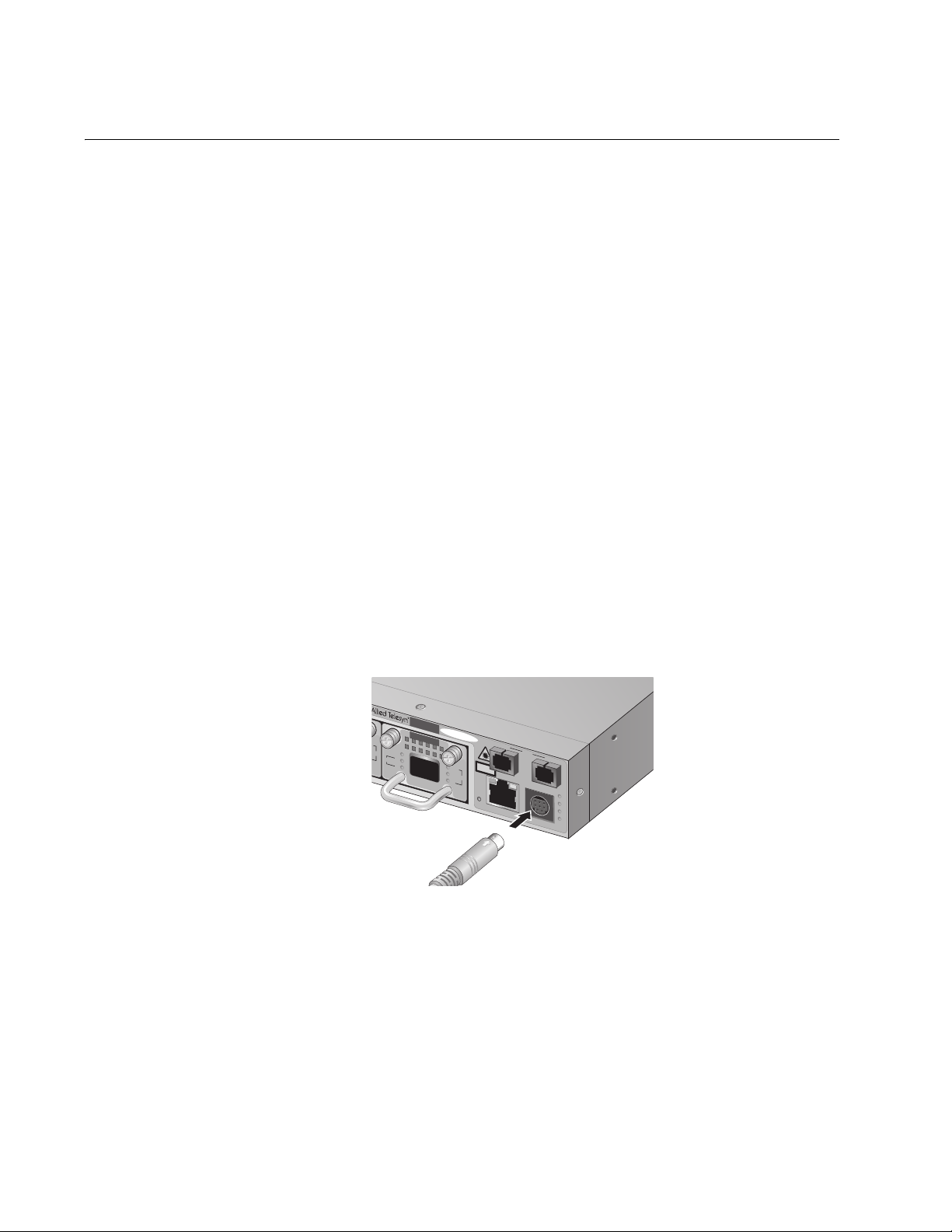
Local Management Session
You establish a local management session with the AT-LX3800U chassis
when you use the management cable included with the chassis to connect
a terminal or PC with a terminal emulation program to the RS-232 port on
the chassis. The RS-232 port is located on the front panel of the
AT-LX3800U chassis and has a DIN-8 style connector.
This type of management session is referred to as “local” because you
must be physically close to the chassis, such as in the wiring closet where
the chassis is located.
After the session starts, the menus are displayed from which you can
make selections to configure and manage the chassis. You can configure
all of the chassis operating parameters from a local management session.
A chassis does not need an Internet Protocol (IP) address for you to
manage it locally. You can start a local management session on the
chassis at any time and not interfere with the chassis operations.
Starting a Local
Management
Session
To start a local management session on the chassis, perform the following
procedure:
1. Connect the DIN-8 end of the management cable included with the
AT-LX3800U chassis to the RS-232 terminal port on the front of the
chassis, as shown in Figure 1.
8
8
AT-LX3800U
AT-LX3811/8
RDY
LINE
TX
TRIB
R
X
SYNC
TX
SFP
R
X
154
LINE
TX
CLASS 1
LASER PRODUCT
100 10
R
E
S
E
T
10/100Base-TX
LINE
TERMINAL
RS-232
RX
FT
CO
PA
P
B
154
Figure 1. Connecting the Management Cable to the RS-232 Port
2. Connect the other end of the cable to an RS-232 port on a terminal or
PC with a terminal emulation program.
14
3. Configure the terminal or terminal emulation program to the following
settings:
Baud rate: 115200 (default value)
Data bits: 8
Page 15

AT-S65 Management Software User’s Guide
Parity: None
Stop bits: 1
Flow control: None
Note
These settings are for a DEC VT100 or ANSI terminal, or an
equivalent terminal emulation program.
The software initializes.
4. Press Return.
The Login prompt is displayed.
5. To configure chassis settings, enter “manager” as the user name. To
only view the settings, enter “operator” as the user name.
The Password prompt is displayed.
6. To configure chassis settings, enter “friend” as the password for a
manager login. To only view the settings, enter “operator” as the
password for an operator login.
The Main Menu is displayed, as shown in Figure 2.
Allied Telesyn AT-LX3800U
Main Menu
Module Status and Configuration
Administration
System Configuration
Quit
Figure 2. AT-S65 Main Menu
Refer to “Using the Menus Interface” on page 19 for information about how
to move through the menus and make menu selections.
Quitting a Local
Management
Session
To end a local management session, return to the Main Menu and select
Quit.
15
Page 16

Chapter 1: Getting Started
Note
The AT-S65 management software supports only one management
session at a time. Therefore, it is important to always quit a
management session when you are finished managing the chassis.
Otherwise, you might block future management sessions or
software downloads. You can configure a timeout value so that the
chassis automatically disconnects a management session after a
defined period of inactivity. The default timeout is 5 minutes. To
configure a different timeout value, refer to “Specifying a Timeout
Value” on page 49.
16
Page 17
Remote Management Session
You can use the Telnet application from any workstation on your network
to manage an AT-LX3800U system. This type of management session is
referred to as remote management because you do not need to be
physically close to the chassis to start the session.
A remote management session allows you to access the same menus and
options that you can access with a local management session.
To manage a chassis remotely, you must first assign an IP address to it,
as described in “Configuring the IP Address, Subnet Mask, and Default
Gateway” on page 24 using a local management session.
AT-S65 Management Software User’s Guide
Starting a
Remote
Management
Session
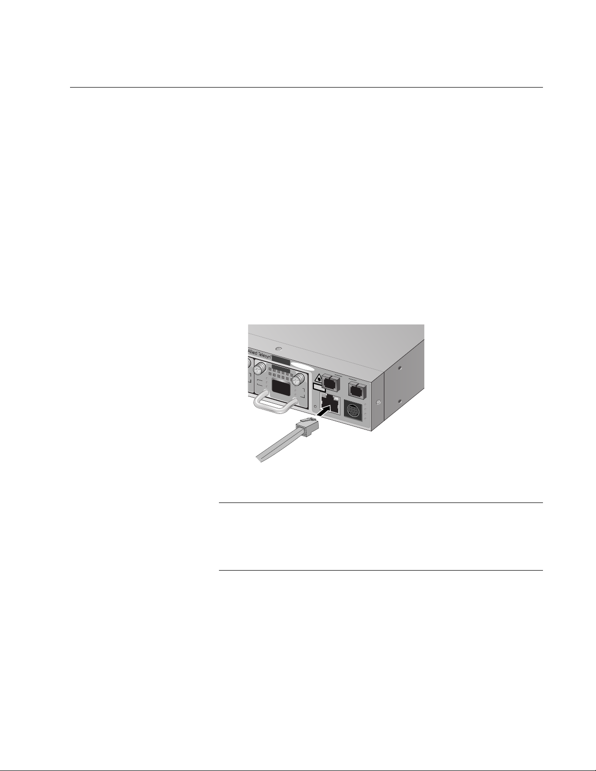
To start a remote management session, perform the following procedure:
1. Connect a twisted pair cable to the 10/100Base-T port on the front of
the chassis, as shown in Figure 3.
8
8
AT-LX3800U
AT-LX3811/8
RDY
LINE
TX
TR
IB
RX
SYNC
TX
SFP
RX
LINE
TX
CLASS 1
LASER PRODUCT
100 10
R
E
S
ET
10/100Base-TX
LINE
TERMINAL
RS-232
RX
FT
C
O
PA
PB
155
Figure 3. Connecting a Cable to the 10/100Base-T Port
Note
The RJ-45 port runs in MDIX mode. Be sure to use the proper cable.
The connector and port pinouts are shown in Appendix A, “Technical
Specifications,” the AT-LX3800U Multi-Service Transport System
Installation and Maintenance Guide.
2. In the Telnet application, specify the IP address of the AT-LX3800U
chassis that you want to access.
The software initializes and then the Login prompt is displayed.
3. To configure chassis settings, enter “manager” as the user name. To
only view the settings, enter “operator” as the user name.
17
Page 18

Chapter 1: Getting Started
The Password prompt is displayed.
4. To configure chassis settings, enter “friend” as the password for a
manager login. To only view the settings, enter “operator” as the
password for the operator login.
The Main Menu is displayed, as shown in Figure 2 on page 15.
Refer to “Using the Menus Interface” on page 19 for information about
how to move through the menus and make menu selections.
Quitting a
Remote
Management
Session
To end a remote management session, return to the Main Menu and
select Quit.
Note
The AT-S65 management software supports only one management
session at a time. Therefore, it is important to always quit a
management session when you are finished managing the chassis.
Otherwise, you might block future management sessions or
software downloads. You can configure a timeout value so that the
chassis automatically disconnects a management session after a
defined period of inactivity. The default timeout is 5 minutes. To
configure a different timeout value, refer to “Specifying a Timeout
Value” on page 49.
18
Page 19

Using the Menus Interface
Refer to Table 1 for information about how to move through the menus
and make menu selections.
When directed to You must
Select an option Highlight the option by pressing
AT-S65 Management Software User’s Guide
Table 1. Using the AT-S65 Menus Interface
the up (
↑) or down (↓) arrow key;
then press Enter.
or
Type the first character of the
desired option and press Enter.
Enter information (for example, the
IP address of the chassis)
Type the information and press
Enter.
Return to the previous menu Select the “Return” option at the
bottom of the menu.
or
Press Esc.
Activated options are preceded by a > symbol. In the following example,
the Start Log option is activated.
Activity Monitor
> Start Log
Stop Log
When you press Enter to select a field in which you can enter a value, the
-> symbol is displayed. For example:
Contact: ->
The -> symbol indicates that you can enter a new value for the option or
change the existing value. After you enter a value, press Enter again. To
delete an existing value without entering a new value, press the space bar
and then press Enter.
All changes are immediately activated on the chassis.
19
Page 20

Chapter 1: Getting Started
SNMP Management Session
Another way to remotely manage an AT-LX3800U chassis is to use an
SNMP management application such as HP OpenView or AT-View Plus.
To use an SNMP management application, you should be familiar with
management information base (MIB) objects. You must download the
AT-LX3800U MIB file from the Allied Telesyn web site and compile the file
with your SNMP program. For instructions, refer to your SNMP
management documentation.
20
Page 21

Chapter 2
Basic Parameters
This chapter describes how to configure basic parameters on the chassis
and contains the following procedures:
“Configuring Basic Chassis Parameters” on page 22
“Setting the System Date and Time” on page 28
“Configuring the Trap Parameters” on page 30
“Setting the Temperature Thresholds” on page 33
“Pinging a Remote System” on page 37
“Resetting and Restarting the System” on page 39
“Changing the RS-232 Terminal Baud Rate” on page 40
“Displaying and Naming the Ethernet Port” on page 42
“Returning the AT-S65 Management Software to the Factory Default
Values” on page 44
21
Page 22

Chapter 2: Basic Parameters
Configuring Basic Chassis Parameters
The AT-S65 management software provides options to configure some
basic parameters on the chassis. This section contains the following
procedures:
“Configuring the Chassis Name, Location, and Contact,” next
“Configuring the IP Address, Subnet Mask, and Default Gateway” on
page 24
“Configuring the Manager IP Addresses” on page 24
“Configuring the SNMP Community Strings” on page 25
“Enabling or Disabling DHCP” on page 25
Configuring the
Chassis Name,
Location, and
Contact
To configure the chassis name, location, and contact, perform the
following procedure:
1. From the Main Menu, select System Configuration.
The System Configuration Menu is shown in Figure 4.
System Configuration Menu
System Name: Null (not configured)
System Time Options
Omega Options
IP Parameters
Trap Parameters
Terminal Configuration
Temperature Threshold Configuration
Return to Main Menu...
22
Figure 4. System Configuration Menu
2. From the System Configuration Menu, select System Name and press
Enter.
The name can be up to 20 alphanumeric characters, including spaces
and special characters. To delete a system name without entering a
new name, press the space bar. This name is displayed at the top of
every AT-S65 menu.
Page 23

AT-S65 Management Software User’s Guide
3. Type a name for the system and press Enter.
4. Select IP Parameters and press Enter.
The IP Parameters Menu is shown in Figure 5.
IP Parameters Menu
IP Address: Null (not configured)
Subnet Mask: 255.255.0.0
Gateway Address: Null (not configured)
Manager Address1: Null (not configured)
Manager Address2: Null (not configured)
Manager Address3: Null (not configured)
Manager Address4: Null (not configured)
Get Community String: public
Set Community String: private
Trap Community String: public
Location: Null (not configured)
Contact: Null (not configured)
> Disable DHCP
Enable DHCP
Return to System Configuration Menu ...
Figure 5. IP Parameters Menu
5. Adjust the following parameters as necessary:
Location
The physical location of the system, for example, Third Floor Network
Operations. The location can be up to 20 alphanumeric characters,
including spaces and special characters. To delete a location without
entering a new name, press the space bar.
Contact
The name, phone number, and other information that identifies the
person responsible for managing the system.The contact information
can be up to 20 alphanumeric characters, including spaces and special
characters. To delete the contact information without entering a new
name, press the space bar.
23
Page 24

Chapter 2: Basic Parameters
Note
The IP Address, Subnet Mask, and Default Gateway parameters are
described in “Configuring the IP Address, Subnet Mask, and Default
Gateway,” next. The Manager IP addresses are described in
“Configuring the Manager IP Addresses” on page 24. The Disable
DHCP and Enable DHCP parameters are described in “Enabling or
Disabling DHCP” on page 25.
Configuring the
IP Address,
Subnet Mask, and
Default Gateway
To configure parameters for managing the chassis remotely, perform the
following procedure:
1. From the Main Menu, select System Configuration.
The System Configuration Menu is shown in Figure 4 on page 22.
2. From the System Configuration Menu, select IP Parameters and
press Enter.
The IP Parameters Menu is shown in Figure 5 on page 23.
3. Adjust the following parameters as necessary:
IP Address
Specifies the IP address of the chassis. You must specify an IP
address, subnet mask, and gateway address if you intend to use
Telnet or an SNMP management application to manage the chassis
remotely. In addition, if the management station is separated from the
chassis by a router, you must also provide a gateway address, which
is the IP address of a router through which the chassis can
communicate with the remote management station.
Subnet Mask
The subnet mask for the chassis. You must assign a subnet mask to
manage the chassis remotely.
Configuring the
Manager IP
Addresses
24
Gateway Address
The IP address of the default router. You must assign a subnet mask
to manage the chassis remotely if a router separates the management
station from the chassis.
4. After you have adjusted the parameters, return to the Main Menu.
You can specify up to four network management stations that will receive
SNMP traps from the system.
To configure the manager IP addresses, perform the following procedure:
1. From the Main Menu, select System Configuration.
Page 25

AT-S65 Management Software User’s Guide
The System Configuration Menu is shown in Figure 4 on page 22.
2. From the System Configuration Menu, select IP Parameters and
press Enter.
The IP Parameters Menu is shown in Figure 5 on page 23.
3. Adjust the following parameters as necessary:
Manager Address1 through Manager Address 4
Specifies up to four IP addresses of network management stations that
will receive SNMP traps from the chassis. This is optional.
4. After you have adjusted the parameters, return to the Main Menu.
Configuring the
SNMP
Community
Strings
To configure the SNMP community strings, perform the following
procedure:
1. From the Main Menu, select System Configuration.
The System Configuration Menu is shown in Figure 4 on page 22.
2. From the System Configuration Menu, select IP Parameters and
press Enter.
The IP Parameters Menu is shown in Figure 5 on page 23.
3. Adjust the following parameters as necessary: A community string can
be a maximum of 20 characters.
Get Community String
The default setting for this string is “public.”
Set Community String
A default setting for this string is “private.”
Trap Community String
The default setting for this string is “public.”
4. After you have adjusted the parameters, return to the Main Menu.
Enabling or
Disabling DHCP
The Dynamic Host Control Protocol (DHCP) client software is included
with the AT-S65 management software. When you enable DHCP, the
system obtains its IP address, subnet mask, and default gateway address
from the DHCP server. In order for this feature to work, there must be a
DHCP server that resides on your network.
Note
Enabling DHCP overrides any IP configuration settings that you
manually assigned.
25
Page 26

Chapter 2: Basic Parameters
Note
Boot Protocol (BOOTP), another protocol that performs an identical
function, is not available on the AT-LX3800U system.
To enable or disable DHCP, perform the following procedure:
1. From the Main Menu, select System Configuration.
The System Configuration Menu is shown in Figure 4 on page 22.
2. From the System Configuration Menu, select IP Parameters and
press Enter.
The IP Parameters Menu is shown in Figure 5 on page 23.
3. Select one of the following parameters:
Disable DHCP
Disables DHCP on the chassis.
Enable DHCP
Enables DHCP. If you enable DHCP, you must reset the chassis in
order for the internal management module to start issuing DHCP
requests to obtain its IP configuration.
The chassis issues up to three requests for its IP configuration from
the DHCP server. If the DHCP server does not respond, the chassis
uses the assigned IP address, if one was manually assigned.
26
Page 27

AT-S65 Management Software User’s Guide
When you choose Enable DHCP, the IP Parameters Menu is refreshed
to show the settings, as shown in Figure 6.
IP Parameters Menu
IP Address: [using 145.39.8.189 from DHCP]
Subnet Mask: [using 255.255.255.0 from DHCP]
Gateway Address: [using 149.39.8.1 from DHCP]
Manager Address1: Null (not configured)
Manager Address2: Null (not configured)
Manager Address3: Null (not configured)
Manager Address4: Null (not configured)
Get Community String: public
Set Community String: private
Trap Community String: public
Location: Null (not configured)
Contact: Null (not configured)
Disable DHCP
> Enable DHCP
Return to System Configuration Menu ...
Figure 6. IP Parameters Menu with DHCP Values
4. After you have adjusted the parameters, return to the Main Menu.
27
Page 28

Chapter 2: Basic Parameters
Setting the System Date and Time
Setting the system time is important if you configured the chassis to send
traps to your management stations. If the time is not set, traps do not
contain the correct date and time. Therefore, it becomes difficult for you to
determine when the events represented by the traps occurred.
There are two ways to set the time: manually and using Simple Network
Time Protocol (SNTP). When you set the time manually, the chassis loses
the values when it is reset or power cycled. When you use this method,
you must reset the values whenever you reset the chassis.
When you set up SNTP, the chassis obtains the current date and time
from an SNTP or Network Time Protocol (NTP) server located on your
network or on the Internet. The AT-S65 management software contains
the client version of SNTP. SNTP is a reduced version of NTP. However,
the SNTP client software in the AT-S65 management software is
interoperable with NTP servers.
To set the system’s date and time, perform the following procedure:
1. From the Main Menu, select System Configuration.
The System Configuration Menu is shown in Figure 4 on page 22.
2. From the System Configuration Menu, select System Time Options
and press Enter.
The System Time Configuration Menu is shown in Figure 7.
System Time Configuration Menu
System Date (mm/dd/yyyy): 01/01/1980
System Time (hh:mm:ss): 00:00:00
SNTP Status: Disabled
SNTP Server: Null (not configured)
UTC Offset (-12 to 12): 0
Daylight Savings Time: Disabled
28
Poll Interval (Seconds): 0
Last Delta (Seconds): 0
Return to System Configuration Menu ...
Figure 7. System Time Configuration Menu
Page 29

AT-S65 Management Software User’s Guide
3. Adjust the following parameters as necessary:
System Date (mm/dd/yyyy)
Enter a date for the system. Use two numbers for the day and month.
Use four numbers to specify the year. Separate the values with
slashes. For example, December 5, 2004 is specified as 12/05/2004.
Note that if you then enable SNTP, the date you set is superseded by
information obtained from the SNTP server.
System Time (hh:mm:ss)
Enter a time for the system in the following format: hours, minutes, and
seconds, separated by colons. Note that if you then enable SNTP, the
system time is superseded by information obtained from the SNTP
server.
SNTP Status
This option either enables or disables the SNTP client on the chassis.
The default is Disabled. After SNTP is enabled, the chassis
immediately polls the SNTP or NTP server for the current date and
time.
SNTP Server
If you set SNTP Status to Enabled, you must specify the IP address of
an SNTP server.
UTC Offset (-12 to 12)
Coordinated Universal Time (UTC), the international time standard,
formerly referred to as Greenwich Mean Time (GMT). The offset is the
number of hours from -12 to 12 that the time for the chassis differs
from UTC. The default is 0.
Daylight Savings Time
Select Enabled to enable daylight savings time, and allow the chassis
to adjust its system time to daylight savings time. Or, select Disabled to
disable daylight savings time. The default is disabled.
Poll Interval (seconds)
Specifies the time interval between queries to the SNTP server. The
default is 0.
Last Delta (seconds)
This read-only field displays the last adjustment that was applied to the
system time due to a drift in the system clock between two successive
queries to the SNTP server.
4. After you have adjusted the parameters, return to the Main Menu.
29
Page 30

Chapter 2: Basic Parameters
Configuring the Trap Parameters
The trap parameters specify which traps are sent to the SNMP
management stations specified in “Configuring the Manager IP
Addresses” on page 24.
To set the trap parameters, perform the following procedure:
1. From the Main Menu, select System Configuration.
The System Configuration Menu is shown in Figure 4 on page 22.
2. From the System Configuration Menu, select Trap Parameters and
press Enter.
The Trap Parameters Menu is shown in Figure 8.
Trap Parameters Menu
Chassis Over-Temperature: 1
Module Over-Temperature: 1
SFP Over-Temperature: 1
SFP Loss of Signal: 1
Module Loss of Signal: 0
Module Out of Sync: 0
SFP Insert/Removal: 3
Module Insertion/Removal: 2
RPS Failure: 0
RPS Insertion/Removal: 2
Port Active/Shutdown: 2
Fan Failure: 2
Module Mode Change 1,3,4
Cold Start: 0
Authentication: 2
Return to System Configuration Menu ...
Figure 8. Trap Parameters Menu
The numbers following each trap relate to the list of IP addresses of
management stations as shown in Figure 6 on page 27.
The number “1” following a trap represents “Manager Address1” in the
IP Parameters Menu, number “2” represents “Manager Address2,” and
so forth. You use this numbering to control which management
stations receive which traps. For example, if you want “Manager
Address1” and “Manager Address3” to receive the RPS traps, then
you would change the RPS trap items to show the number “1,3.” The
default is 0 (zero); no management stations receive traps.
30
Page 31

AT-S65 Management Software User’s Guide
3. Enter or change the parameters as desired.
Changes to the parameters take effect immediately on the chassis.
The traps are described in Table 2.
Table 2. SNMP Traps
Trap Description
Chassis Over-Temperature The chassis temperature has exceeded
the set threshold. For information about
setting the chassis temperature threshold,
refer to “Configuring the Chassis
Temperature Threshold” on page 33.
Module Over-Temperature The temperature of a line card has
exceeded the set threshold. For
information about setting the line card
temperature threshold, refer to
“Configuring the Line Card Temperature
Threshold” on page 34.
SFP Over-Temperature The SFP transceiver’s temperature has
exceeded the set threshold. For
information about setting the SFP
temperature threshold, refer to
“Configuring the SFP Temperature
Threshold” on page 35.
SFP Loss of Signal The SFP has been disconnected from the
client port fiber.
Module Loss of Signal The line port has been disconnected from
the line port fiber.
Module Out of Sync The line card is out of synch.
SFP Insertion/Removal An SFP has been inserted into or
removed from a line card.
Module Insertion/Removal A line card has been inserted into or
removed from the system.
RPS Failure A redundant power supply (RPS) has
failed.
RPS Insertion/Removal An RPS has been inserted into or
removed from its slot.
Port Active/Shutdown The port is active or has been shut down.
Fan Failure A failure has occurred in one of the fan
modules.
31
Page 32

Chapter 2: Basic Parameters
Table 2. SNMP Traps (Continued)
Trap Description
Module Mode Change The operating mode of the line card has
changed. See “Setting the Line Card’s
Mode of Operation” on page 76 for more
information.
Cold Start The chassis has been power cycled.
Authentication An SNMP management application has
attempted to perform a Set function, and
the Set community string on an SNMP
management application is different from
the same community string on the
chassis.
32
Page 33

Setting the Temperature Thresholds
You can set a maximum temperature threshold for the chassis, line cards,
and the SFPs in line cards. Whenever a temperature threshold is
exceeded, the chassis sends a trap to the management stations defined in
the Trap Parameters Menu, as described in “Configuring the Trap
Parameters” on page 30. This section contains the following procedures:
“Configuring the Chassis Temperature Threshold,” next
“Configuring the Line Card Temperature Threshold” on page 34
“Configuring the SFP Temperature Threshold” on page 35
AT-S65 Management Software User’s Guide
Configuring the
Chassis
Temperature
Threshold
To set the chassis temperature threshold, perform the following procedure.
1. From the Main Menu, select System Configuration.
The System Configuration Menu is shown in Figure 4 on page 22.
2. From the System Configuration Menu, select Temperature Threshold
Configuration and press Enter.
The Temperature Threshold Configuration Menu is shown in Figure 9.
Temperature Threshold Configuration Menu
Chassis Temperature Threshold Configuration
Line Card Temperature Threshold Configuration
SFP Temperature Threshold Configuration
Return to System Configuration Menu ...
Figure 9. Temperature Threshold Configuration Menu
3. From the Temperature Threshold Configuration Menu, select Chassis
Temperature Threshold Configuration and press Enter.
33
Page 34

Chapter 2: Basic Parameters
The Chassis Temperature Threshold Configuration Menu is shown in
Figure 10.
Chassis Temperature Threshold Menu
Maximum Temperature Threshold: 60
Return to Temperature Threshold Configuration Menu ...
Figure 10. Chassis Temperature Threshold Menu
4. From the Chassis Temperature Threshold Menu, select Maximum
Temperature Threshold.
5. Enter a number for the Maximum Temperature Threshold and press
Enter.
The highest possible maximum temperature is 75° C.
6. After you have adjusted the parameters, return to the Main Menu.
Configuring the
Line Card
Temperature
Threshold
Module Number:
To set the line card temperature threshold, perform the following
procedure.
1. From the Main Menu, select System Configuration.
The System Configuration Menu is shown in Figure 4 on page 22.
2. From the System Configuration Menu, select Temperature Threshold
Configuration.
The Temperature Threshold Configuration Menu is shown in Figure 9
on page 33.
3. From the Temperature Threshold Configuration Menu, select Line
Card Temperature Threshold Configuration and press Enter.
The Line Card Temperature Threshold Configuration Menu is shown in
Figure 11.
Line Card Temperature Configuration Menu
34
Maximum Temperature Threshold: 70
Return to Temperature Threshold Configuration Menu ...
Figure 11. Line Card Temperature Configuration Menu
Page 35

AT-S65 Management Software User’s Guide
4. From the Line Card Temperature Configuration Menu, select Module
Number.
5. Type the number of the line card where the SFP is located and press
Enter.
6. Select Maximum Temperature Threshold.
7. Enter a number for the Maximum Temperature Threshold and press
Enter.
The highest possible maximum temperature is 120° C. The default is
75°C.
8. After you have adjusted the parameters, return to the Main Menu.
Configuring the
SFP Temperature
Threshold
To set the temperature threshold for an SFP in a line card, perform the
following procedure:
1. From the Main Menu, select System Configuration.
The System Configuration Menu is shown in Figure 4 on page 22.
2. From the System Configuration Menu, select Temperature Threshold
Configuration and press Enter.
The Temperature Threshold Configuration Menu is shown in Figure 9
on page 33.
3. From the Temperature Threshold Configuration Menu, select SFP
Temperature Threshold Configuration and press Enter.
The SFP Temperature Threshold Configuration Menu is shown in
Figure 12.
SFP Temperature Threshold Menu
Module Number:1
Maximum Temperature Threshold: 70
Return to Temperature Threshold Configuration Menu ...
Figure 12. SFP Temperature Threshold Configuration Menu
4. From the SFP Temperature Threshold Menu, select Module Number.
5. Type the number of the line card where the SFP is installed.
6. Select Maximum Temperature Threshold.
35
Page 36

Chapter 2: Basic Parameters
7. Enter a number for the Maximum Temperature Threshold and press
Enter.
The highest possible maximum temperature is 100° C. The default is
75°C.
8. After you have adjusted the parameters, return to the Main Menu.
Note
The option to set the temperature threshold for an SFP is only
available on SFPs that support this feature.
36
Page 37

Pinging a Remote System
You can instruct the chassis to ping a remote device on your network. This
procedure is useful in determining whether a valid link exists between the
chassis and another device. The chassis sends an Internet Control
Message Protocol (ICMP) echo request to the end node. If the node is
operating and receives the request, it sends a reply to the chassis.
Note
You can only ping a remote device when you are connected
remotely.
To instruct the chassis to ping a network device, perform the following
procedure:
1. From the Main Menu, select Administration.
AT-S65 Management Software User’s Guide
The Administration Menu is shown in Figure 13.
Administration Menu
Xmodem Software Update to this System
Image Download Through TFTP
Ping a Remote System
Syslog Server Address: Null (not configured)
Syslog Facility Code: 1
Event Log
Activity Monitor
> Start Log
Stop Log
Outstanding Errors
Diagnostics
Reset and Restart the System
Reset Database to Default
Return to Main Menu ...
Figure 13. Administration Menu
37
Page 38

Chapter 2: Basic Parameters
Note
The first two options on this menu are described in Chapter 6,
”Downloading AT-S65 Management Software Updates” on page 83.
The Reset and Restart the System option is described in “Resetting
and Restarting the System” on page 39. The remaining options are
described in Chapter 4, ”Monitoring System Performance” on page
51.
2. From the Administration Menu, select Ping a Remote System and
press Enter.
The Ping menu is shown in Figure 14.
Please enter station IP address to ping:
Note: Ping will repeat until a key is pressed.
->
Figure 14. Ping Menu
3. Enter the IP address of the device you want the chassis to ping and
press Enter.
The display, as shown in Figure 15, reports the results of the Ping
command.
Ping a Remote System
Ping Request: 3, Ping Reply: 3, Ping Lost: 0
Figure 15. Ping Results Example
A Ping command continues until you stop it by pressing any key.
4. Return to the Main Menu.
38
Page 39

Resetting and Restarting the System
When you reset a system, the system is also restarted. Resetting and
restarting the system is a way to refresh all the statistics displays or
overcome system errors. This process does not affect any system
settings, return the system to its default values, or affect traffic entering or
leaving the line card’s physical line. However, it does terminate your
management session and you must log in again after the reset is
complete.
To reset and restart the system, perform the following procedure:
1. From the Main Menu, select Administration.
The Administration Menu is shown in Figure 13 on page 37.
2. From the Administration Menu, select Reset and Restart the System
and press Enter.
AT-S65 Management Software User’s Guide
The Reset and Restart the System Menu is shown in Figure 16.
Do reset system now? (Yes or No):
Yes
>No
Return to Administration Menu ...
Figure 16. Reset and Restart the System Menu
3. Select Yes to reset the system or No to cancel the command.
The reset process usually takes less than a minute.
4. Log in again to manage the system.
39
Page 40

Chapter 2: Basic Parameters
Changing the RS-232 Terminal Baud Rate
The default settings for the RS-232 terminal port are:
Baud rate: 115200
Data bits: 8
Parity: None
Stop bits: 1
Flow control: None
To set the RS-232 port to a different baud rate, perform the following
procedure:
1. From the Main Menu, select System Configuration.
The System Configuration Menu is shown in Figure 4 on page 22.
2. From the System Configuration Menu, select Terminal Configuration
and press Enter.
The Terminal Configuration menu is shown in Figure 17.
Terminal Configuration Menu
Data Rate (Baud Rate)
Return to System Configuration Menu ...
Figure 17. Terminal Configuration Menu
3. From the Terminal Configuration Menu, select Data Rate and press
Enter.
40
Page 41

AT-S65 Management Software User’s Guide
The Terminal Data Rate menu is shown in Figure 18.
Terminal Data Rate Menu
> 115200 bps
19200 bps
9600 bps
4800 bps
2400 bps
Return to Terminal Configuration Menu ...
Figure 18. Terminal Data Rate Menu
4. Select the baud rate you want and press Enter.
The default is 115200. To avoid connection problems, always set the
terminal data rate and the baud rate in your terminal emulation
program to the same setting.
5. Return to the Main Menu.
Changes to the baud rate take effect the next time you start a local
management session.
41
Page 42

Chapter 2: Basic Parameters
Displaying and Naming the Ethernet Port
To display information about the 10/100Base-T Ethernet port and give it a
name, perform the following procedure:
1. From the Main Menu, select Module Status and Configuration.
The Module Status and Configuration Menu is shown in Figure 19.
Module Status and Configuration Menu
Module -------------WDM Side------------------------------Port Side----------
Status Tx Rx T_SYN R_SYN MaxRate TX Rx SFP
1: Not Present Unknown
2: Not Present Unknown
3: AT-LX3811/2 MISMATCH
4: Not Present Unknown
5: Not Present Unknown
6: Not Present Unknown
7: AT-LX3811/7 On Offline Offline Off Off OM Offline Offline Out
8: Not Present Unknown
9: MGMT BOARD Off
10: AT-RPSA
11: Not Present Unknown
12: AT-CPU FAN1 On
13: AT-CPU FAN2 On
14: AT-CPU FAN On
Return to Main Menu ...
2. Select item 9 and press Enter.
Figure 19. Module Status and Configuration Menu
The MGMT BOARD module reflects the status of the 10/100 Ethernet
port.
42
Page 43

AT-S65 Management Software User’s Guide
The MGMT BOARD menu is shown in Figure 20.
9: MGMT BOARD
Port Link
Tx Online
Module name
Return to Module Status and Configuration Menu ...
Figure 20. MGMT BOARD (Ethernet Port) Menu
The MGMT BOARD menu shows the current status of the Ethernet
port:
Port
This item always displays “Tx.”
Link
The status of the connection, which can be one of the following:
Offline - The port does not have an active connection.
Online - The port has an active connection.
3. To give the port a name, select Module name and press Enter.
The name can contain up to 20 alphanumeric characters, including
spaces and special characters.
4. Type a name for the module and press Enter.
5. Return to the Main Menu.
43
Page 44

Chapter 2: Basic Parameters
Returning the AT-S65 Management Software to the Factory Default Values
To return the AT-S65 management software to the factory default values,
perform the following procedure:
1. From the Main Menu, select Administration.
The Administration Menu is shown in Figure 13 on page 37.
2. From the Administration Menu, select Reset Database to Default and
press Enter.
The message in Figure 21 is displayed.
Reset database to default now? (Yes or No):
Yes
>No
Return to Administration Menu ...
Figure 21. Reset Management Software Menu
3. Select Yes and press Return.
The following message is displayed:
Database has been set to default, now rebooting the
system . . .
The software is reset to the default values (see Appendix A, “AT-S65
Management Software Default Settings” on page 99), the system is
rebooted, and you must log in again.
Note
The system time and date are not reset to the default values.
44
Page 45

Chapter 3
Menus Interface Security
The AT-S65 management software includes features that allow you to
configure the interface to prevent unauthorized individuals from accessing
the software and making changes to the AT-LX3800U configuration
settings. This chapter contains the following procedures:
“Setting Up Manager and Operator Passwords” on page 46
“Enabling or Disabling Access Methods” on page 48
“Specifying a Timeout Value” on page 49
45
Page 46

Chapter 3: Menus Interface Security
Setting Up Manager and Operator Passwords
To prevent unauthorized individuals from accessing the AT-S65
management software, you can specify a password a user is required to
enter in order to access the software. Any person who starts the AT-S65
management software, either as a manager or as an operator, is required
to enter the password. The password is required whether they access the
software locally or remotely.
To specify a new password, perform the following procedure:
1. From the Main Menu, choose System Configuration.
The System Configuration Menu is shown in Figure 22.
System Configuration Menu
System Name: Null (not configured)
System Time Options
Omega Options
IP Parameters
Trap Parameters
Terminal COnfiguration
Temperature Threshold Configuration
Return to Main Menu...
Figure 22. System Configuration Menu
2. From the System Configuration menu, select Omega Options and
press Enter.
46
Page 47

AT-S65 Management Software User’s Guide
The Omega Options Menu is shown in Figure 23.
Omega Options Menu
Manager Password: *****************
Operator Password: *****************
Timeout 5
> Local Omega Enabled
Disable Local Omega
> Remote Omega Enabled
No Remote Omega
Return to System Configuration Menu...
Figure 23. Omega Options Menu
3. From the Omega Options menu, select Manager Password or
Operator Password.
Note
When you change these passwords, you change the default system
passwords for the Manager and Operator logins. The default
Manager password is “friend” and the default Operator password is
“Operator.”
The password can be up to 20 alphanumeric characters in length.
Avoid using special characters such as a spaces, asterisks, and
exclamation points. The password is case sensitive.
When you type the password, it is displayed as a series of
asterisks.
To delete the current password but not assign a new password,
enter a space in the password field.
4. Enter a new password and then press Enter.
The new password for the manager or operator login is now activated
on the system.
5. Return to the Main Menu.
47
Page 48

Chapter 3: Menus Interface Security
Enabling or Disabling Access Methods
As explained in Chapter 1, you can access the AT-LX3800U system
locally through the RS-232 terminal port or remotely using the Telnet
application. You can disable either method to enhance security by
preventing unauthorized individuals from making changes to the system’s
configuration settings.
To enable or disable an access method, perform the following procedure:
1. From the Main Menu, choose System Configuration.
The System Configuration menu is shown in Figure 22 on page 46.
2. From the System Configuration menu, select Omega Options and
press Enter.
The Omega Options menu is shown in Figure 23 on page 47.
3. To enable or disable local access, select Local Omega Enabled or
Disable Local Omega.
These options control local access to the AT-S65 management
software on the AT-LX3800U system. The default is enabled.
4. To enable or disable remote access, select Remote Omega Enabled
or No Remote Omega.
These options control remote access to the AT-S65 management
software on the AT-LX3800U system. The default is enabled.
5. Return to the Main Menu.
48
Page 49

Specifying a Timeout Value
Specifying a timeout value is a way to prevent unauthorized individuals
from using the management software in the event that you forget to exit
the software and leave your management station unattended. When you
specify a timeout value, the AT-S65 management software ends the
session when it detects that there has been no activity in the amount of
time you specify as the timeout value. The default timeout value is 5
minutes.
To enter a new timeout value, perform the following procedure:
1. From the Main Menu, choose System Configuration.
The System Configuration Menu is shown in Figure 22 on page 46.
2. From the System Configuration menu, select Omega Options and
press Enter.
AT-S65 Management Software User’s Guide
The Omega Options menu is shown in Figure 23 on page 47.
3. Select Timeout and press Enter.
4. Enter a value from 0 (zero) to 65,535 (minutes) and press Enter.
When you enter a value of 0 (zero), there is no timeout and the session
remains active until you end the session. If you enter a value of 0, you
must always quit the management software in order not to block future
sessions and software downloads to the system. The default is 5
minutes.
The new timeout value is immediately activated on the system.
5. Return to the Main Menu.
49
Page 50

Chapter 3: Menus Interface Security
50
Page 51

Chapter 4
Monitoring System Performance
This chapter describes the features in the AT-S65 management software
for monitoring the performance of the AT-LX3800U Multi-Service
Transport System and contains the following sections:
“Displaying System Status Information” on page 52
“Using the System Activity Monitor” on page 54
“Using the Event Log” on page 57
“Displaying Outstanding Errors” on page 60
“Specifying a SysLog Server” on page 62
“Using the System Diagnostics” on page 63
51
Page 52

Chapter 4: Monitoring System Performance
Displaying System Status Information
The AT-S65 management software provides comprehensive status
information about the operation of the chassis and its components,
including detailed information about the line cards.
To view chassis status information, perform the following procedure:
1. From the Main Menu, select Module Status and Configuration.
The Module Status and Configuration Menu is shown in Figure 24.
Module Status and Configuration Menu
Module -------------WDM Side------------------- ----------Port Side----------
Status Tx Rx T_SYN R_SYN MaxRate TX Rx SFP
1: Not Present Unknown
2: Not Present Unknown
3: AT-LX3811/2 MISMATCH
4: Not Present Unknown
5: Not Present Unknown
6: Not Present Unknown
7: AT-LX3811/7 On Offline Offline Off Off OM Offline Offline Out
8: Not Present Unknown
9: MGMT BOARD Off
10: AT-RPSA
11: Not Present Unknown
12: AT-CPU FAN1 On
13: AT-CPU FAN2 On
14: AT-CPU FAN3 On
Return to Main Menu ...
52
Figure 24. Module Status and Configuration Menu
The Module Status and Configuration Menu displays basic information
about all the components currently installed in the chassis, including:
Line cards (items 1 through 8)
Management board (Ethernet port) (Item 9)
Main and redundant power supplies (items 10 and 11)
Chassis fans (items 12 through 14)
The “WDM Side” information coordinates with the Line LEDs, and the
“Port Side” coordinates with the Trib LEDs on the line cards.
For details about the line card information on this menu and how to
display detailed information, refer to Chapter 5, “Working With Line
Page 53

AT-S65 Management Software User’s Guide
Cards” on page 67. For information about the Ethernet port, refer to
“Displaying and Naming the Ethernet Port” on page 42.
53
Page 54

Chapter 4: Monitoring System Performance
Using the System Activity Monitor
The AT-S65 management software keeps a list of AT-LX3800U system
events such as the removal of an SFP or the loss of a data link. This list is
called the activity log and you use the activity monitor to display the log.
The activity log contains only those events that have occurred since you
started the management session. Ending the session purges the log. The
activity log can contain up to 256 events. When the maximum number of
events is reached, new events are added to the beginning of the file and
old ones are deleted.
In contrast, the event log contains all system events since the
AT-LX3800U system was last rebooted. For information about the event
log, refer to “Using the Event Log” on page 57.
This section contains the following procedures:
“Starting and Stopping the Activity Log,” next
Starting and
Stopping the
Activity Log
Displaying the
Activity Log
“Displaying the Activity Log” on page 54
To start or stop the activity log, perform the following procedure:
1. From the Main Menu, select Administration.
The Administration menu is shown in Figure 13 on page 37.
2. From the Administration menu, under Activity Monitor, select Start
Log to start the activity log or Stop Log to stop the activity log. The
default is Start Log.
To view the activity log, perform the following procedure:
1. From the Main Menu, select Administration.
The Administration menu is shown in Figure 13 on page 37.
2. From the Administration menu, select Activity Monitor and press
Enter.
54
Page 55

AT-S65 Management Software User’s Guide
The Activity Monitor is shown in Figure 25.
Activity Monitor
(Press Return to resume the previous menu)
04:26:17 0:04:42:01:CLEAR:Line Card 3 Wavelength Mismatch
04:26:17 0:04:42:01:REPORT:Line Card 3 Missing
04:26:17 0:04:42:01:REPORT:Line Card 3 Wavelength Mismatch
04:26:17 0:04:42:01:CLEAR:Line Card 3 Missing
04:26:17 0:04:42:01:REPORT:Line Card 3 SFP Link Down
04:26:17 0:04:42:01:REPORT:Line Card 3 RX Synchronization Failed
04:26:17 0:04:42:01:REPORT:Line Card 3 SFP Transceiver is Disabled
Figure 25. Activity Monitor
The activity monitor continues to display system activities until you
press Enter to return to the previous menu and select Stop Log.
The activity log messages are described in Table 3. The messages
shown in the activity log are the same as those shown in the event log
described in “Using the Event Log” on page 57. Each message is
preceded either by “REPORT” or “CLEAR.” REPORT indicates that an
error is being reported, and CLEAR indicates that the error has been
cleared. The “n” in the message indicates the number of the line card,
fan module, and so forth where the event occurred.
Table 3. Activity and Event Log Events
Event Description
Chassis Temperature Exceed High Limit The chassis temperature has exceeded the
set maximum limit.
Fan Module n Failed A chassis fan has failed.
Line Card n Missing The line card is missing from the slot.
Line Card n RX Synchronization Failed The line card’s receive port synchronization
has failed.
Line Card n SFP Link Down The receive port on the SFP has a loss of
signal.
Line Card n SFP Port Shutdown The SFP port has been shut down.
Line Card n SFP Rate Changed The line card rate has changed.
Line Card n SFP Temperature Exceed High Limit The temperature of the SFP has exceeded
the set maximum temperature.
55
Page 56

Chapter 4: Monitoring System Performance
Table 3. Activity and Event Log Events (Continued)
Event Description
Line Card n SFP Transceiver is Disabled The transmit port of an SFP has been
disabled.
Line Card n SFP Unplugged The SFP in a line card has been unplugged
and/or removed.
Line Card n Temperature Exceed High Limit The temperature of the line card has
exceed the set maximum temperature.
Line Card n TX Synchronization Failed The line card’s transmit port
synchronization has failed.
Line Card n Wavelength Mismatch The line card inserted in the slot does not
match the wavelength for that slot.
Line Card n WDM Channel Down The line card’s receive port has lost the
signal.
Line Card n WDM Port Shutdown The line card’s transmit port has been shut
down.
Line Card n WDM Transmitter is Disabled The line card’s transmitter has been
disabled.
Power Module n Failed A power supply has failed.
Power Module n Inserted A power supply has been inserted into the
chassis.
Power Module n Removed A power supply has been removed from
the chassis.
System Cold Reboot The system has been rebooted by turning
the power switch off and then on.
56
Page 57

Using the Event Log
The event log provides vital information about chassis activity that helps
you identify and solve system problems. The event log permanently stores
system event information in a file saved in flash memory on the system.
The file can contain up to 511 events. When the maximum number of
events is reached, new events are added to the beginning of the file and
old ones are deleted.
In contrast, the activity log as described in “Using the System Activity
Monitor” on page 54 contains only those events that occurred since you
started the latest management session.
AT-S65 Management Software User’s Guide
Displaying the
Event Log
To display the event log, perform the following procedure:
1. From the Main Menu, select Administration.
The Administration menu is shown in Figure 13 on page 37.
2. From the Administration menu, select Event Log and press Enter.
The Event Log menu is shown in Figure 26.
Event Log Menu
Display Event Log
Clear Event Log
Return to Administration Menu ...
Figure 26. Event Log Menu
3. From the Event Log menu, select Display Event Log and press Enter.
57
Page 58

Chapter 4: Monitoring System Performance
The event log is displayed, as shown in Figure 27.
Event Log
Total Events: 511 Displaying: 505 to 511
Date Time Message
----------------------------------------------------------------------------01/11/04 04:26:17 0:04:42:01: CLEAR:Line Card 1 WDM Channel Down
01/11/04 04:26:17 0:04:42:01: REPORT:Line Card 3 Missing
01/11/04 04:26:17 0:04:42:01: REPORT:Line Card 3 Wavelength Mismatch
01/11/04 04:26:17 0:04:42:01: CLEAR:Line Card 3 Missing
01/11/04 04:26:17 0:04:42:01: REPORT:Line Card 3 SFP Link Down
01/11/04 04:26:17 0:04:42:01: REPORT:Line Card 3 RX Synchronization Failed
01/11/04 04:26:17 0:04:42:01: REPORT:Line Card 3 SFP Transceiver is Disabled
N - Next Page, P - Previous Page, F - First Page, L - Last Page, R - Return
Figure 27. Event Log
Clearing the
Event Log
The Event Log menu provides the following information:
Total Events
The total number of events currently stored in the event log.
Displaying
Of the total number of events in the event log, the range of events
currently displayed.
Date and Time
The date and time that the event occurred.
Message
This information starts with the number of hours, minutes, and
seconds that the chassis has been running since it was last powered
on. The messages reported in the event log are identical to those
reported in the activity log. For a list of these messages, refer to Table
3, “Activity and Event Log Events” on page 55.
4. Return to the Main Menu.
To clear the event log, perform the following procedure:
1. From the Main Menu, select Administration.
58
The Administration menu is shown in Figure 13 on page 37.
2. From the Administration menu, select Event Log and press Enter.
The Event Log menu is shown in Figure 26 on page 57.
Page 59

AT-S65 Management Software User’s Guide
3. From the Event Log menu, select Clear Event Log.
The following message is displayed while the event log is being
cleared:
Please wait while the event log is cleared.
Followed by:
Done!
4. Return to the Main Menu.
59
Page 60

Chapter 4: Monitoring System Performance
Displaying Outstanding Errors
Outstanding errors are hardware errors that require immediate attention.
The most recent outstanding error is displayed at the bottom of every
menu you view, and all the current outstanding errors are shown on the
Outstanding Errors menu. Most outstanding errors report line cards that
are inserted in the wrong slot (mismatched).
To display the outstanding errors, perform the following procedure:
1. From the Main Menu, select Administration.
The Administration menu is shown in Figure 13 on page 37.
2. From the Administration menu, select Outstanding Errors and press
Enter.
An example of the Outstanding Errors menu is shown in Figure 28.
Outstanding Errors
0:00:06:22: REPORT: Line Card 5 Wavelength Mismatch
Press any key to continue ...
Critical Error: 0:00:13:04 REPORT: Line Card 4 Wavelength Mismatch
Please see Outstanding Error Menu for more Error Messages
Figure 28. Outstanding Errors Menu
The most recent error is shown at the bottom of this and all S65
menus. Any older errors are shown above.
The error in the example above shows that wavelength mismatch error
indicates that line cards 4 and 5 are inserted in the wrong slots.
60
Page 61

AT-S65 Management Software User’s Guide
Note
A line card inserted in the wrong slot (mismatched) cannot pass data
(traffic).
These errors are the same as those shown in the activity and event
logs. For more information, refer to Table 3, “Activity and Event Log
Events” on page 55.
61
Page 62

Chapter 4: Monitoring System Performance
Specifying a SysLog Server
The syslog protocol allows you to collect messages and events produced
by a wide variety of network equipment in a single place. For instance,
instead of viewing the event logs of several separate AT-LX3800U
systems, you can have those events sent to a single syslog server on your
network. The destination for the events is referred to as a facility code.
To transmit the system events to a syslog server, perform the following
procedure:
1. From the Main Menu, select Administration.
The Administration menu is shown in Figure 13 on page 37.
2. From the Administration menu, select Syslog Server Address and
press Enter.
3. Enter the IP address of a syslog server on the network.
4. Select SysLog Facility Code.
Assign a facility code to the chassis log messages. The range is 0 to
23 and the default is 1. The facility code generally used for system
events is 23, or you can use whatever facility number you have already
set up on your network.
5. Type the facility code and press Enter.
6. Return to the Main Menu.
62
Page 63

Using the System Diagnostics
The AT-S65 management software provides an option to run diagnostic
self-tests on the chassis and line cards. The following section describes
how to run chassis diagnostics. Using this information helps you diagnose
performance problems with the chassis. For information about the line
card diagnostics, refer to “Displaying the Line Card Diagnostics” on
page 86.
To run chassis diagnostics, perform the following procedure:
1. From the Main Menu, select Administration.
The Administration menu is shown in Figure 13 on page 37.
2. From the Administration menu, select Diagnostics and press Enter.
The Diagnostics Menu is shown in Figure 29.
AT-S65 Management Software User’s Guide
Diagnostics Menu
Chassis Diagnostics
Line Card Diagnostics
Return to Administration Menu ...
Figure 29. Diagnostics Menu
3. From the Diagnostics Menu, select Chassis Diagnostics and press
Enter.
63
Page 64

Chapter 4: Monitoring System Performance
MAC Address: 00:30:84:00:00
WDM Chassis: AT-LX3800
Serial Number: S05525A022600001 Hardware Revision: A
Running 3 hours, 15 minutes, 24 seconds
Current Time: 07/30/2004 06:42:08
Diagnostic Results:
Flash PROM: Good Voltage (+5V): +4.914 V
Serial Interface: Good Voltage (+3.3V):+3.213 V
Temperature: 30.5 Celsius
Fan 1 (Chassis): Good Fan 1 (Chassis) Speed: 4753 RPM
Fan 2 (Chassis): Good Fan 2 (Chassis) Speed: 4753 RPM
Fan 3 (Chassis): Good Fan 3 (Chassis) Speed: 4753 RPM
RPS A: On Fan1: Good Fan2: Good
RPS B: Not PresentFan1: Not PresentFan2: Not Present
The AT-S65 management software runs the diagnostics on the
chassis and displays the Chassis Diagnostics menu, as shown in
Figure 30.
Chassis Diagnostics
Press any key to continue ...
Figure 30. Chassis Diagnostics Menu
The top portion of the Chassis Diagnostics menu contains the
following items of information:
MAC Address
The MAC address of the chassis.
WDM Chassis
The AT-LX3800U chassis revision number.
Serial Number/Hardware Revision
The serial number and hardware revision level of the system.
Running
The number of hours, minutes, and seconds that the chassis has been
running since it was last powered on.
Current Time
The current time set on the chassis.
The lower portion of the Chassis Diagnostics menu contains
diagnostic information about the following:
64
Page 65

AT-S65 Management Software User’s Guide
Flash PROM
The status of the Flash PROM and its current voltage.
Serial Interface
The status of the RS-232 terminal port and its current voltage.
Fan 1 through Fan 3
The status of the chassis fans and their current speed.
RPSA and RPSB
The status of the power supplies including whether or not the power
supply is turned on and the status of the two fans it contains. The
chassis can function with only one power supply, referred to as RPSA
or RPSB in this menu.
4. Return to the Main Menu.
65
Page 66

Chapter 4: Monitoring System Performance
66
Page 67

Chapter 5
Working With Line Cards
The AT-S65 management software provides several ways that you can
The AT-S65 management software provides several ways that you can
view information about the line cards and run diagnostics on a line card.
view information about the line cards and run diagnostics on a line card.
For diagnostic information about the overall system, refer to Chapter 4,
For diagnostic information about the overall system, refer to Chapter 4,
“Monitoring System Performance” on page 51.
“Monitoring System Performance” on page 51.
This chapter contains the following sections:
This chapter contains the following sections:
“Displaying Basic Line Card Information” on page 68
“Displaying Basic Line Card Information” on page 68
“Displaying Detailed Line Card Information” on page 70
“Displaying Detailed Line Card Information” on page 70
“Changing Basic Line Card Settings” on page 74
“Changing Basic Line Card Settings” on page 74
“Setting the Line Card’s Mode of Operation” on page 76
“Setting the Line Card’s Mode of Operation” on page 76
“Displaying the Line Card Diagnostics” on page 86
“Displaying the Line Card Diagnostics” on page 86
67
Page 68

Chapter 5: Working With Line Cards
Displaying Basic Line Card Information
The AT-S65 software provides a menu that displays an overview of the
status of all the components in the system.
To view the system status and configuration, perform the following
procedure:
1. From the Main Menu, select Module Status and Configuration.
The Module Status and Configuration Menu is shown in Figure 24 on
page 52.
Items 1 through 8 in the Module Status and Configuration Menu
display two groups of information about the line cards:
WDM Side
The status of the WDM (line) side of the line card, that coordinates with
the Line group of LEDs. The columns of information in this section are:
Status
The current status of the line card, which can be one of the
following:
Unknown - No line card inserted.
MISMATCH - The line card in this slot is not the correct line card
designated for the slot.
On - The correct line card is inserted in this slot and the power is
on.
Tx
The status of the transmit WDM port, which can be one of the
following:
Offline - The transmitter is disabled.
Online - The transmitter is enabled.
Rx
The status of the receive WDM port, which can be one of the
following:
Offline - The receiver input power is less than -38 dBm ± 2 dB.
68
Online - The receiver input power is greater than -38 dBm ± 2 dB.
T_SYN
The status of the synchronization of the TX path, which can be one
of the following:
Off - The data is not synchronized (locked) on a transmit path.
Page 69

AT-S65 Management Software User’s Guide
On - The data is synchronized (locked) on a transmit path.
R_SYN
The status of the synchronization of the RX path, which can be one
of the following:
Off - The data is not synchronized (locked) on a receive path.
On - The data is synchronized (locked) on a receive path.
Port Side
The status of the port (SFP) side of the line card, that coordinates with
the Trib group of LEDs. The columns of information in this section are:
Max Rate
The maximum rate for the SFP installed in the line card. This
information is only available when an SFP is installed.
Tx
The status of the transmit (SFP) port, which can be one of the
following:
Offline - The SFP transmitter is disabled.
Online - The SFP transmitter is enabled.
Rx
The status of the receive (SFP) port, which can be one of the
following:
Offline - The SFP input power is less than the threshold value for
Rx loss specified by the vendor.
Online - The SFP input power is higher than or equal to the
threshold value for Rx loss specified by the vendor.
SFP
The status of the SFP in the line card, which can be one of the
following:
In - An SFP is inserted in the SFP slot.
Out - No SFP is inserted in the SFP slot.
69
Page 70

Chapter 5: Working With Line Cards
Displaying Detailed Line Card Information
The AT-S65 management software provides detailed information about
the line cards including items such as temperature, data rate, wavelength,
and vendor information for the SFP. The procedures in this section
include:
“Displaying Line Card Status Information,” next
“Changing the Line Card Name and Location” on page 74
“Enabling or Disabling a Line Card” on page 74
“Displaying SFP Vendor Information” on page 73
Displaying Line
Card Status
Information
Module Name:
Port Link
Tx Offline
Rx Offline
Wavelength 1470
Temperature 41.8 Celsius
Current Data Rate 0.0 Mbps
To display detailed line card status information, perform the following
procedure:
1. From the Main Menu, select Module Status and Configuration.
The Module Status and Configuration Menu is shown in Figure 24 on
page 52.
2. Select the line card whose information you want to display and press
Enter.
An example of the Module Status Menu for an AT-LX3811/1 line card
is shown in Figure 31.
1: AT-LX3811/1
70
Module Location:
Module Information
Vendor Information
Module Status Enabled
Port Status Enabled
Line Card Mode of Operation
Return to Line Card Status and Configuration Menu ...
Figure 31. Sample Line Card Information
Page 71

AT-S65 Management Software User’s Guide
The Module Status Menu provides the following information:
Name
The name can be up to 20 alphanumeric characters including spaces
and special characters. You may want to choose a name that reflects
the organization or group that is connected through this line card.
Port/Link
Indicates whether there is an active connection between the SFP port
and the device connected to it, which is one of the following:
Tx - The status of the transmit port, which can be one of the following:
Offline: The SFP transmitter is disabled.
Online: The SFP transmitter is enabled.
Rx - The status of the receive port, which can be one of the following:
Offline: The SFP input power is less than the threshold value for Rx
loss specified by the vendor.
Online: The SFP input power is higher than or equal to the threshold
value for Rx loss specified by the vendor.
Wavelength
The wavelength of the line transmitter’s laser.
Temperature
The current temperature of the line card.
Current Data Rate
The current data rate of the line card ± 10%.
Module Location
For information about setting up this information, refer to “Changing
the Line Card Name and Location” on page 74.
Module Information
For information about displaying this detailed information, go to step 3.
Vendor Information
For information about displaying this information, refer to “Displaying
SFP Vendor Information” on page 73.
Module Status
The status of the line card. The options are:
Enabled - Enables the lasers on the port (SFP) and WDM (line) sides.
This is the default.
Disabled - Disables the lasers on the port and WDM sides but does not
terminate traffic.
71
Page 72

Chapter 5: Working With Line Cards
Port Status
The status of the SFP port. The options are:
Enabled - Enables the laser on the SFP transceiver. This is the
default.
Disabled - Disables the laser on the SFP transceiver but does not
terminate traffic.
Line Card Mode of Operation
Opens a menu where you set the line card’s mode of operation.
For more information about the line card’s mode of operation, refer to
“Setting the Line Card’s Mode of Operation” on page 76.
3. To display more detailed information about the SFP transceiver, select
Module Information and press Enter.
The detailed SFP transceiver information is displayed, as shown in
Figure 32. The information varies depending upon the SFP transceiver
whose information you are displaying.
Module Information Menu
1: AT-LX3811
Type of Serial Transceiver: 3(Vendor Specific)
SONET Compliance Codes: 22(OC 12, single mode intermediate reach)
Gigabit Ethernet Compliance Codes: 2(1000BASE-LX)
Fiber Channel Link Length: 20(Intermediate)
Fiber Channel Transmitter Type: 1(Long wave laser)
Fiber Channel Media Type: 1(Single mode fiber)
Fiber Channel Speed: 14 (400MB/s)
Encoding: 05(8B10B)
Normal Baud Rate: 19(2.5GHz)
9micro, Distance: 2(Not supported)
50micro, Distance: 0(Not Supported)
60micro, Distance: 0(Not Supported)
CU, Distance: 0(Not Supported)
Transmit Disable: 1(Supported)
Laser Fault: 1(Supported)
Signal Detect(Logical 0): 0(Not Supported)
Signal Detect(Logical 1): 1(Supported)
Upper Baud Rate Margin: 60(96%)
Lower Baud Rate Margin: 08(8%)
Return to previous menu ...
4. Return to the Main Menu.
72
Figure 32. Detailed SFP Transceiver Information Menu
Page 73

AT-S65 Management Software User’s Guide
Displaying SFP
Vendor
Information
To display SFP vendor information, perform the following procedure:
1. From the Main Menu, select Module Status and Configuration.
The Module Status and Configuration Menu is shown in Figure 24 on
page 52.
2. Select the line card whose information you want to display and press
Enter.
The Module Status Menu for that line card is displayed. An example of
that menu is shown in Figure 31 on page 70.
3. Select Vendor Information and press Enter.
Details about the SFP inserted in that line card are displayed. An
example of that display is shown in Figure 33. The information varies
depending upon what the vendor has programmed into the SFP.
2: AT-LX3811
Vendor name (OUI): FINISAR CORP.
Vendor IEEE company ID: 009065
Vendor part number: FTRJ1319P1BTL-AT
Vendor revision number: A
Vendor serial number: P651VEW
Vendor date code: 040812
Vendor specific ID: AT-SPLX10 A02419N0408V001R
Return to previous menu...
Figure 33. SFP Vendor Information
4. Return to the Main Menu.
73
Page 74

Chapter 5: Working With Line Cards
Changing Basic Line Card Settings
You can change the following settings to fit your network needs:
“Changing the Line Card Name and Location,” next
“Enabling or Disabling a Line Card” on page 74
Changing the
Line Card Name
and Location
To change the name and location of the line card, perform the following
procedure:
1. From the Main Menu, select Module Status and Configuration.
The Module Status and Configuration Menu is shown in Figure 24 on
page 52.
2. Select the line card whose information you want to change and press
Enter.
The Module Status Menu for that line card is displayed. An example of
that menu is shown in Figure 31 on page 70.
3. Select Name and press Enter.
Enter a name for the line card and press Enter. You may want to
choose a name that reflects the group connected to that line card,
such as Engineering. The name can contain up to 20 alphanumeric
characters, spaces, and special characters.
4. Select Module Location and press Enter.
Enter a name for the location and press Enter. For instance, the name
of a city to which the line card is sending traffic. The location contain
up to 20 alphanumeric characters, spaces, and special characters.
Enabling or
Disabling a Line
Card
74
5. Return to the Main Menu.
When you enable a line card, you make it available to send and receive
network traffic. If a line card TX or RX LED for the LINE side of the card
are flashing green or off, the card may be disabled. The default is enabled.
To verify if a line card is enabled or disabled, or to change that setting,
perform the following procedure:
1. From the Main Menu, select Module Status and Configuration.
The Module Status and Configuration Menu is shown in Figure 24 on
page 52.
Page 75

AT-S65 Management Software User’s Guide
2. Select the line card whose information you want to change and press
Enter.
The Module Status Menu for that line card is displayed. An example of
that menu is shown in Figure 31 on page 70.
3. Select Module Status and press Enter.
The options are:
Enabled - Enables the line card. This is the default.
Disabled - Disables the line card.
4. Press Enter to change the selection.
5. Return to the Main Menu.
75
Page 76

Chapter 5: Working With Line Cards
Setting the Line Card’s Mode of Operation
You can choose one of seven modes of operation for the ports on a line
card. The modes determine what response the line card makes when an
optical signal is present or interrupted. The modes include a default mode
and six other modes divided into two groups: three missing link disabled
modes and three fixed loopback modes, as shown in Table 4.
Table 4. Line Card Modes of Operation
Group
Missing Link
Disabled
Fixed Loopback 5 Port loopback enabled.
In the missing link modes, the data path automatically changes depending
upon the presence or absence of an optical signal. The default and all the
fixed loopback modes provide only fixed data paths.
The value of these operation modes is that you can configure some
switches to take a specific action when a connection is lost. In some
cases, you can configure the unit to seek a redundant path to the
disconnected node and send out a trap to a network management station,
alerting the network administrator of the problem.
Mode
No.
1 Port and line card missing link enabled.
(Default)
2 Port missing link disabled, line missing
link enabled.
3 Port missing link enabled, line issing link
disabled.
4 Port and line missing link disabled.
6 Port and line loopback enabled.
7 Line loopback enabled.
Description
76
You can use the loopback modes for troubleshooting and mode 3 or mode
7 in a regeneration application.
Page 77

AT-S65 Management Software User’s Guide
Figure 34 shows four AT-LX3800U systems in a regeneration
configuration. The line cards in the regeneration units (site B) are
configured in either mode 7 (line loopback enabled) or mode 3 (port
missing link enabled, line missing link disabled). If you choose mode 3, the
line card automatically switches from line loopback configuration to a
passthrough configuration as soon as the SFP port receives an optical
signal. Ifno signal is received on the SFP port, then mode 3 operates in the
same way as mode 7.
Site B
Regeneration Location
RX
Site A
TX
AT-LX3800U
RX
AT-LX3800U
TX
Site C
RX
AT-LX3800U
TX
TX
AT-LX3800U
RX
Figure 34. Regeneration Configuration Using Mode 7
All of the modes are described in detail in the following sections.
77
Page 78

Chapter 5: Working With Line Cards
Default Mode In the default mode (mode 1 shown in Figure 35), missing link is enabled
for both the port (SFP) and line (WDM) sides. This mode allows the
system to pass the status of its connections to the next stage in the data
path.
Line
X
Side
CWDM
Transciever
X
SFP
Port
Side
X
Case A:
Port side: no optical
signal received
Line side: optical signal
received
Line
Side
CWDM
Transciever
SFP
Port
Side
Case B:
Case B:
Port side: optical
Port side: optical
signal received
signal received
Line side: optical
Line side: optical
signal received
signal received
Line
X
Side
CWDM
Transciever
X
SFP
Port
Side
X
Case C:
Port side: optical signal
received
Line side: no optical
signal received
Line
X
X
Side
CWDM
Transciever
X
X
SFP
Port
Side
X
X
Case D:
Port side: no optical
signal received
Line side: no optical
signal received
78
Legend
No optical signal
Optical signal present
Figure 35. Mode 1: Missing Link Enabled for Port Side and Line Side
(Default Mode)
For example, if the port (SFP) side of a local AT-LX3800U system in
default mode does not receive a signal (Figure 35, case A), then the
corresponding line (WDM) side is shut down and the remote AT-LX3800U
does not get a signal. If the remote system is also in default mode, then
the corresponding port (SFP) side is shut down. (See Case C in Figure
35.) Therefore, the status of the port side of a local system propagates to
the remote system’s port side.
Page 79

AT-S65 Management Software User’s Guide
Missing Link
Disabled Modes
CWDM
Transciever
To prevent a link from shutting down when a failure occurs somewhere in
the signal path, use one of the missing link disabled modes.
In the first missing link mode (#2) shown in Figure 36, in case C, when
there is no optical signal received on the line side, the port (SFP) side
output is activated and the port (SFP) side input is looped back to the SFP
output. As soon as an optical signal reaches the line side, the line card
reconfigures itself to pass-through operation (case B in Figure 36).
X
X
Line
Side
CWDM
Transciever
Line
Side
X
CWDM
Transciever
Line
Side
X
X
CWDM
Transciever
X
X
Line
Side
SFP
Port
Side
X
Case A:
Port side: no optical
signal received
Line side: optical signal
received
Figure 36. Mode 2: Missing Link Disabled for Port Side and Enabled for
SFP
Port
Side
Case B:
Port side: optical
signal received
Line side: optical
signal received
SFP
Port
Side
Case C:
Port side: optical signal
received
Line side: no optical
signal received
Line Side
SFP
Port
Side
X
X
Case D:
Port side: no optical
signal received
Line side: no optical
signal received
Legend
No optical signal
Optical signal present
79
Page 80

Chapter 5: Working With Line Cards
Figure 37 describes mode #3. When missing link is enabled for the port
(SFP) side and disabled for the WDM (line side). When the port side does
not receive an optical signal (Case A), the WDM (line side) signal loops
back to the line side.
Line
Side
CWDM
Transciever
SFP
Port
Side
X
Case A:
Port side: no optical
received
Line side: optical signal
received
Line
Side
CWDM
Transciever
SFP
Port
Side
Case B:
Port side: optical
signal received
Line side: optical
signal received
Line
X
Side
CWDM
Transciever
X
SFP
Port
Side
X
Case C:
Port side: optical signal
receovedt
Line side: no optical
signal received
Line
XX
Side
CWDM
Transciever
X
X
SFP
Port
Side
XX
Case D:
Port side: no optical
signal received
Line side: no optical
signal received
80
Legend
No optical signal
Optical signal present
Figure 37. Mode 3: Missing Link Enabled for Port Side and Disabled for
Line Side
Page 81

AT-S65 Management Software User’s Guide
In mode 4, the third missing link mode (Figure 38), missing link is disabled
on both the port and line sides. Case A shows that if there is no received
signal at the port (SFP) side then the line side loops back to itself. Case C
shows that if there is no received signal on the WDM (line) siden then the
port (SFP) side loops back to itself.
Line
Side
CWDM
Transciever
SFP
Port
Side
X
Case A:
Port side: no optical
signal received
Line side: optical signal
received
Line
Side
CWDM
Transciever
SFP
Port
Side
Case B:
Port side: optical
signal received
Line side: optical
signal received
X
Line
Side
CWDM
Transciever
SFP
Port
Side
Case C:
Port side: optical signal
received
Line side: no optical
signal received
Line
X
X
Side
CWDM
Transciever
X
X
SFP
Port
Side
X
X
Case D:
Port side: no optical
signal received
Line side: no optical
signal received
Fixed Loopback
Mode
Legend
No optical signal
Optical signal present
Figure 38. Mode 4: Missing Link Disabled for Port and Line Sides
In fixed loopback mode, the data paths are fixed. Fixed loopback operates
in one of three ways: loopback on the port (SFP) side only (Figure 39),
loopback on both the port and line sides (Figure 40), or loopback on the
line side only (Figure 41).
81
Page 82

Chapter 5: Working With Line Cards
In mode 5 (Figure 39), loopback on the port side only, input to the port
(SFP) side loops back and also propagates to the WDM (line) side as
shwon in cases B and C..
Line
X
Side
CWDM
Transciever
X
X
SFP
Port
Side
X
X
Case A:
Port side: no optical
signal received
Line side: optical signal
received
Line
Side
CWDM
Transciever
SFP
Port
Side
Case B:
Port side: optical
signal received
Line side: optical
signal received
Line
X
Side
CWDM
Transciever
SFP
Port
Side
Case C:
Port side: optical signal
received
Line side: no optical
signal received
Line
X
X
Side
CWDM
Transciever
X
X
SFP
Port
Side
XX
Case D:
Port side: no optical
signal received
Line side: no optical
signal received
82
Legend
No optical signal
Optical signal present
Figure 39. Mode 5: Loopback on the Port Side Only
Page 83

AT-S65 Management Software User’s Guide
When loopback is set for both the port and line sides as in mode 6
(Figure 40), the received optical signal on either side loops back.
Line
Side
CWDM
Transciever
X
SFP
Port
Side
X
X
Case A:
Port side: no optical
signal received
Line side: optical signal
received
Line
Side
CWDM
Transciever
SFP
Port
Side
Case B:
Port side: optical
signal received
Line side: optical
signal received
Line
X
X
Side
CWDM
Transciever
X
SFP
Port
Side
Case C:
Port side: optical signal
received
Line side: no optical
signal received
Line
X
X
Side
CWDM
Transciever
X
X
SFP
Port
Side
X
X
Case D:
Port side: no optical
signal received
Line side: no optical
signal received
Legend
No optical signal
Optical signal present
Figure 40. Mode 6: Loopback on Port and Line Sides
83
Page 84

Chapter 5: Working With Line Cards
Figure 41 shows loopback set for the line side only (mode 7). Optical
signal input at the WDM (line) side is looped back and also propagated to
the port (SFP) side.
Line
Side
CWDM
Transciever
SFP
Port
Side
X
Case A:
Port side: no optical
signal received
Line side: optical signal
received
Line
Side
CWDM
Transciever
SFP
Port
Side
Case B:
Port side: optical
signal received
Line side: optical
signal received
Line
X
X
Side
CWDM
Transciever
X
X
SFP
Port
Side
X
Case C:
Port side: optical signal
received
Line side: no optical
signal received
Line
XX
Side
CWDM
Transciever
X
X
SFP
Port
Side
X
X
Case D:
Port side: no optical
signal received
Line side: no optical
signal received
Changing the
Line Card’s
84
Setting or
Mode of
Operation
Legend
No optical signal
Optical signal present
Figure 41. Mode 7: Loopback on the Line Side Only
To set the line card’s mode of operation, perform the following procedure:
1. From the Main Menu, select Module Status and Configuration.
The Module Status and Configuration Menu is shown in Figure 24 on
page 52.
2. Select the line card whose mode you want to set or change and press
Enter.
Page 85

AT-S65 Management Software User’s Guide
The Module Status Menu for that line card is displayed. An example of
that menu is shown in Figure 31 on page 70.
3. Select Line Card Mode of Operation and press Enter.
The Line Card Mode of Operation menu is shown in Figure 42.
Line Card Mode of Operation
Mode 1 (Default): Port and Line ML Enabled
Mode 2: Port ML Disabled, Line ML Enabled
Mode 3: Port ML Enabled, Line ML Disabled
Mode 4: Port ML Disabled, Line ML Disabled
Mode 5: Port Loopback
Mode 6: Port and Line Loopback
Mode 7: Line Loopback
Return to previous menu...
Figure 42. Line Card Mode of Operation Menu
4. Select one of the following:
Mode 1 (Default): Port and Line ML Enabled
Missing Link is enabled on both the port and line sides.
Mode 2: Port ML Disabled, Line ML Enabled
Missing Link is disabled on the port side but enabled on the line side.
Mode 3: Port ML Enabled, Line ML Disabled
Missing Link is enabled on the port side but disabled on the line side.
Mode 4: Port ML Disabled, Line ML Disabled
Missing Link is disabled on both the port and line sides.
Mode 5: Port Loopback
Loopback is enabled only on the port side.
Mode 6: Port and Line Loopback
Loopbabk is enabled on both the port and line sides.
Mode 7: Line Loopback
Loopback is enabled only on the line side.
5. Return to the Main Menu.
85
Page 86

Chapter 5: Working With Line Cards
Displaying the Line Card Diagnostics
The line card diagnostics provide important information about how the line
card is functioning.
To display the line card diagnostics, perform the following procedure:
1. From the Main Menu, select Administration.
The Administration menu is shown in Figure 13 on page 37.
2. From the Administration menu, select Diagnostics and press Enter.
The Diagnostics Menu is shown in Figure 29 on page 63.
3. From the Diagnostics Menu, select Line Card Diagnostics and press
Enter.
A sample Line Card Diagnostics Menu is shown in Figure 43.
Line Card Diagnostics Menu
1: Not Present -2: Not Present -3: AT-LX3811 Online
4: AT-LX3811 Online
5: Not Present -6: Not Present -7: Not Present -8: Not Present --
Return to Diagnostics Menu ...
Figure 43. Line Card Diagnostics Menu
4. Select the line card whose diagnostics you want to display and press
Enter.
Note
Diagnostics are not available for a line card with the status of “Not
Present.”
86
Page 87

The Module Diagnostics Menu is shown in Figure 44.
Module Diagnostics Menu
Hardware Revision REV A
Firmware Revision REV A
Line Card Part Number AT-LX3811/1
Line Card Serial Number A02007A040400002
Line Card Voltage 3.306 V
Line Card Temperature 46.0 Celsius
Line Card Bias 11.82416 mA
Line Card Transmit Power 2.95589089 dBm
Line Card Receive Power -24 dBm
Current Data Rate 623.770 Mbps
SFP Status Online
Return to Line Card Diagnostics Menu ...
AT-S65 Management Software User’s Guide
Figure 44. Module Diagnostics Menu
The Module Diagnostics Menu contains the following information about
the line card as a whole:
Hardware Revision/Firmware Revision
The revision level of the line card hardware and firmware.
Line Card Part Number
The line card part number.
Line Card Serial Number
The line card serial number.
Line Card Voltage
The current line card voltage ± 1%.
Line Card Temperature
The current temperature of the line card ± 3º C. To set the maximum
line card temperature, refer to “Configuring the Line Card Temperature
Threshold” on page 34.
Line Card Bias
The bias current of the line card transmitter’s laser ± 10%.
Line Card Transmit Power
The line transmitter’s output power ± 2 dB.
Line Card Receive Power
The line receiver’s input power. (Only values less than -24 dBm are
monitored with ± 2 dB accuracy.)
87
Page 88

Chapter 5: Working With Line Cards
Hardware Revision REV A
Firmware Revision REV A
Line Card Part Number AT-LX3811/1
Line Card Serial Number A02007A040400002
Line Card Voltage 3.306 V
Line Card Temperature 46.0 Celsius
Line Card Bias 11.82416 mA
Line Card Transmit Power 2.95589089 dBm
Line Card Receive Power -24 dBm
Current Data Rate 623.770 Mbps
Current Data Rate
The current rate at which the line card is passing data ± 10%.
SFP Status
The status of the SFP in the line card. If no SFP is inserted, the status
is “Unplugged” and no other information is displayed.
When an SFP is inserted in the line card, the menu looks similar to
Figure 45.
Module Diagnostics Menu
SFP Voltage 3.260 V
SFP Temperature 42.6 Celsius
SFP Bias 16.230 mA
SFP Transmit Power -4.71597562 dBm
SFP Receive Power -13.00162275 dBm
Max Data Rate 1500 Mbps
Return to Line Card Diagnostics Menu ...
Figure 45. Line Card Diagnostics Menu with SFP Information
The following SFP information is displayed:
SFP Voltage
The current voltage of the SFP.
SFP Temperature
The current temperature of the SFP.
SFP Bias
The bias current of the SFP transmitter’s laser.
SFP Transmit Power
The transmitted power of the SFP transmitter.
88
SFP Receive Power
The received power of the SFP receiver.
Page 89

AT-S65 Management Software User’s Guide
Max Data Rate
The maximum data rate of the SFP.
Note
The accuracy of the above information depends upon the SFP
vendor’s specification. This information is available only for SFPs
approved by Allied Telesyn.
5. Return to the Main Menu.
89
Page 90

Chapter 5: Working With Line Cards
90
Page 91

Chapter 6
Downloading AT-S65 Management Software Updates
This chapter describes how to download AT-S65 software updates and
contains the following sections:
“Using Xmodem to Update the AT-S65 Management Software” on
page 93
“Using TFTP to Update the AT-S65 Management Software” on
page 96
Note
For instructions on obtaining the latest software updates, refer to
“Management Software Updates” on page 11.
Note the following before you begin either procedure:
You can download a new AT-S65 image file onto the chassis from
either a local or Telnet management session.
You can use Xmodem or TFTP to download the image file from a local
management session.
You must use TFTP to download the image file from a Telnet
management session.
To use TFTP, there must be a node on your network that contains the
TFTP server software, and the new AT-S65 image file must be stored
on that node.
If you are using TFTP, you should start the TFTP server before you
begin the download procedure.
Installing a new AT-S65 software image onto the chassis does not
change the current configuration, for example its IP address, subnet
mask, and name (if already assigned).
Note
The chassis stops forwarding Ethernet traffic after it has downloaded
the image file and begun to initialize the software. Some network
traffic may be lost.
The following procedures assume that you have already obtained the new
software from Allied Telesyn and stored it on the management station from
91
Page 92

Chapter 6: Downloading AT-S65 Management Software Updates
which you will be performing the procedure, or on the TFTP server.
92
Page 93

AT-S65 Management Software User’s Guide
Using Xmodem to Update the AT-S65 Management Software
To download a new AT-S65 software image onto a chassis from a local
management session using Xmodem, perform the following procedure:
1. Establish a local management session on the chassis where you
intend to download the new management software.
2. From the Main Menu, select Administration.
The Administration menu is shown in Figure 13 on page 37.
3. From the Administration menu, select Xmodem Software Update to
this System and press Enter.
A message is displayed, as shown in Figure 46.
Ready to receive software update via Xmodem.
Warning: During software updates, management activity is disabled.
Do Xmodem update now? (Yes or No):
Figure 46. Xmodem Software Update Message
4. Enter Y to start the download process or N to cancel.
If you enter Y, another message is displayed, as shown in Figure 47.
The system is now ready for download. Please start your XMODEM transfer.
Use Hyper Terminal’s “Transfer/Send File’ option to select Filename &
Protocol.
Note: Please select ‘1K Xmodem’ protocol for faster download . . .
Figure 47. Xmodem Message
5. Begin the file transfer.
The following steps show how to perform the transfer using Hilgraeve
HyperTerminal.
93
Page 94

Chapter 6: Downloading AT-S65 Management Software Updates
6. From the HyperTerminal main window, select Send File from the
Transfer menu, as shown in Figure 48.
Figure 48. HyperTerminal Window
The Send File window is shown in Figure 49.
Figure 49. Send File Window
7. Click Browse and specify the location and file name of the image file
to be downloaded onto the chassis.
8. Click in the Protocol field and select as the transfer protocol either
Xmodem or, for a faster download, 1K Xmodem.
9. Click Send.
The software immediately begins downloading onto the chassis. The
Xmodem File Send window shown in Figure 50 on page 95 displays
94
Page 95

AT-S65 Management Software User’s Guide
the current status of the software download. The download process
takes several minutes to complete.
Figure 50. Xmodem File Send Window
After the chassis has downloaded the new image, it begins to initialize
the software, a process that takes approximately one minute to
complete. The chassis does not forward any network traffic during the
initialization process. After the management software is initialized, the
chassis automatically resets.
Note
Wait until the software is initialized before you attempt to reestablish
your management session.
95
Page 96

Chapter 6: Downloading AT-S65 Management Software Updates
Using TFTP to Update the AT-S65 Management Software
If your network uses the TCP/IP protocol, you can use any station on the
network and TFTP software to download a copy of the current AT-S65
management software onto the chassis. The chassis contains the client
portion of the TFTP protocol. The management station you are using must
contain the server portion of the TFTP protocol. Start the TFTP server
before you begin the download procedure.
To download a new software image onto the chassis using TFTP, perform
the following procedure:
1. Establish a local management session on the chassis where you
intend to download the new management software.
2. From the Main Menu, select Administration.
The Administration menu is shown in Figure 13 on page 37.
3. From the Administration menu, select Image Download Through
TFTP and press Enter.
The TFTP Image Download menu is displayed, as shown in Figure 51.
TFTP Image Download
TFTP Server IP: Null (not configured)
Image File Name: Null (not configured)
Start TFTP Download
Return to Administration Menu ...
Figure 51. TFTP Image Download Menu
4. Select TFTP Server IP and press Enter.
5. Enter the IP address of the TFTP server.
6. Select Image File Name and press Enter.
7. Enter the file name of the AT-S65 image file stored on the TFTP
server.
96
8. Select Start TFTP Download.
Page 97

AT-S65 Management Software User’s Guide
A screen similar to Figure 52 is displayed.
TFTP Download in progress... Please wait!
Performing CRC check on Boot Loader. Please wait...
Boot Loader CRC check PASSED.
The Downloading Boot Loader version is same as current version v1.1.0
Skipping this download...
Performing CRC check on Application Image. Please wait...
Application Image CRC check Passed.
Writing ATS65 to Flash, please wait...
Written 65536 bytes,27% completed
Written 131072 bytes,54% completed
Written 196608 bytes,81% completed
Written 241669 bytes,100% completed
Download Summary:
Boot Loader Download: NO
Image Download: YES
Load completed.
Rebooting...
Figure 52. TFTP Download
After the system has downloaded the new image, it reboots the system
and begins to initialize the software, a process that takes
approximately one minute to complete. The system does not forward
any network traffic during the initialization process.
Note
Wait until the software is initialized before you attempt to reestablish
your management session.
97
Page 98

Chapter 6: Downloading AT-S65 Management Software Updates
98
Page 99

Appendix A
AT-S65 Management Software Default Settings
This appendix lists the default settings for the AT-S65 management
software.
IP Parameters
Setting Default
IP Address 0.0.0.0
Subnet Mask 255.255.0.0
Gateway Address 0.0.0.0
System Time
Manager Address 1 through 4 Null
Get community string public
Set community string private
Trap community string public
Location Null
Contact Null
DHCP Disabled
Setting Default
System Date 01/01/1980
System Time 00.00.00
SNTP Status Disabled
SNTP Server 97.108.82.88
UTC Offset 0
Daylight Savings Time Disabled
99
Page 100

Appendix A: AT-S65 Management Software Default Settings
Setting Default
Poll Interval (seconds) 0
Last Delta (seconds) 0
RS-232 Port
Setting Default
Terminal mode VT-100 compatible/ANSI
Data bits 8
Stop bits 1
Parity None
Duplex mode Full-duplex
Data rate 115200
Omega Options
Manager Password Null
Operator Password Null
Timeout 5 minutes
Local Omega Enabled
Remote Omega Enabled
Remote Omega (Telnet) Port Number 23
Temperature Thresholds
Setting Default
100
Setting Default
Chassis Temperature (Maximum) 60
Line Card Temperature (Maximum) 70
SFP Temperature (Maximum) 70
 Loading...