

Page 1

◆
User’s Guide
Management
®
Software
AT-S39
AT-8012M, AT-8016F/xx (SC or MT), AT-8024,
AT-8024GB, AT-8024M, AT-8026FC, AT-8088/xx
(SC or MT) FAST ETHERNET SWITCHES
VERSION 3.1.0
PN 613-50245-00 Rev H
Page 2

Copyright 2003 Allied Telesyn, Inc.
960 Stewart Drive Suite B, Sunnyvale, CA 94085 USA
All rights reserved. No part of this publication may be reproduced without prior written permission from Allied Telesyn, Inc.
Microsoft is a registered trademark of Microsoft Corporation, Netscape Navigator is a registered trademark of Netscape
Communications Corporation. All other product names, company names, logos or other designations mentioned herein are
trademarks or registered trademarks of their respective owners.
Allied Telesyn, Inc. reserves the right to make changes in specifications and other information contained in this document without
prior written notice. The informati on provided h erein is su bject to cha nge without n otice. In n o event sha ll Allied Telesyn, Inc. be liable
for any incidental, special, indirect, or consequential damages whatsoever, including but not limited to lost profits, arising out of or
related to this manual or the information contained herein, even if Allied Telesyn, Inc. has been advised of, known, or should have
known, the possibility of such damages.
Page 3

Table of Contents
List of Figures ........................................................................................................................................................................................................9
Preface ....................................................................................................................................................................................................................12
How This Guide is Organiz ed ............................................................................ ....................... ........................................................................12
Document Conventions ..................................................................... ........................ .......................................................................................14
Where to Find Web-based Guid e s .............................................................. ......................... ..........................................................................15
Contacting Allied Telesyn ... ......................... ......................... ......................... ...................................................................................................16
Sales or Corporate Information ..............................................................................................................................................................16
Management Software Updates ....................................................................................................................................................................17
Section I
Overview
Chapter 1
Overview ................................................................................................................................................................................................................19
Local Management Session ..............................................................................................................................................................................21
Telnet Management Se ssio n ....................... ......................... ......................... ...................................................................................................22
Web Browser Management S essi on ............. ......................... ......................... ......................... ......................................................................23
SNMP Management Session ........... .................................................. ........................ .......................................................................................24
Management Access Levels .............................................................................................................................................................................25
..........................................................................................................................................................18
Section II
Local and Telnet Management
Chapter 2
Starting a Local or Telnet Management Session ................................................................................................................................28
Local Management Session ..............................................................................................................................................................................29
Starting a Local Manage me nt Session.............. ......................... ......................... ........................ ..................... ......................... ........... 30
Enhanced Stacking ........................................................................................................................ ..................... ......................... ............... 33
Quitting from a Local Session..... ......................... .................................................. .......................................................................... ....... 33
Telnet Management Se ssio n ....................... ......................... ......................... ...................................................................................................34
Starting a Telnet Manage me nt Session ... ........................ ......................... ......................... ..................... ......................... ................... 34
Quitting from a Telnet M anagement Session......................... ......................... ........................ .............................................. ........... 35
..................................................................................................26
3
Page 4

Table of Contents
Chapter 3
Basic Switch Parameters ................................................................................................................................................................................36
When Does a Switch Need an IP Address? .......................... ......................... ......................... ..................................................................... 37
How Do You Assign an IP Address?................................ .................................................. ......................... ......................... .................. 38
Configuring an IP Address and Switch Name ...........................................................................................................................................39
Activating the BOOTP and DHCP Services .................................................................................................................................................42
Configuring SNMP Community Strings and Trap IP Addresses ....................... ......................... .........................................................44
Resetting a Switch .............. ......................... ......................... ......................... ......................................................................................................47
Configuring the AT-S39 Software Security Features ........................ ......................... ........................ .... .................................................48
Configuring the Managem e nt Passwords....... ......................... ........................ ......................... ........................................................ 48
Configuring Management Access.................................................................................................................................................. ...... 51
Viewing the AT-S39 Version Number and Switch MAC Address ...... ......................... .........................................................................52
Pinging a Remote System .................... ......................... ......................... ........................ ..................................................................................53
Returning the AT-S39 Software to the Factory Default Values ...........................................................................................................54
Configuring the Console Startup Mode ......................................................................................................................................................55
Configuring BALUN Cable Detection ...........................................................................................................................................................56
Chapter 4
Enhanced Stacking ...........................................................................................................................................................................................57
Enhanced Stacking Overview .........................................................................................................................................................................58
Guidelines...................................................................................................................................... ......................... ....................................... 58
Setting a Switch’s Enhanced Stacking Status ............................. ......................... ......................... .............................................................61
Selecting a Switch in an Enhanced Stack ...................................................................................................................................................63
Returning to the Master Switch......................................................................................................... ......................... ......................... .. 64
Chapter 5
Port Parameters .................................................................................................................................................................................................65
Displaying Port Status ................................................. ........................ ......................... ......................................................................................66
Configuring Port Parameters ..........................................................................................................................................................................69
Displaying Uplink Informat io n ............... ......................... ......................... ......................................................................................................73
Chapter 6
Port Security ........................................................................................................................................................................................................75
Port Security Overview ......................................................................................................................................................................................76
Configuring Port Security .................................................................................................................................................................................78
Configuring the Limited Security Mode ......................................................................................................................................................80
Chapter 7
Port Trunking ......................................................................................................................................................................................................82
Port Trunking Overview ....................................................................................................................................................................................83
Load Distribution Method s................................... ......................... ........................ .............................................. ......................... .......... 84
Creating a Port Trunk .................................................................. ......................... .............................................................................................. 89
Deleting a Port Trunk ..................... ........................ ......................... ......................... ..........................................................................................91
Chapter 8
Port Mirroring .....................................................................................................................................................................................................92
Port Mirroring Overview ...................................................................................................................................................................................93
Creating a Port Mirror ............................ ......................... ......................... ........................ ..................................................................................94
Deleting a Port Mirror ....... ......................... ......................... ......................... ......................................................................................................95
Chapter 9
STP and RSTP .......................................................................................................................................................................................................96
STP and RSTP Overview .....................................................................................................................................................................................97
Bridge Priority and the Root Bridge....................... ......................... ......................... ...................................................................... ...... 98
Mixed STP and RSTP Networks ................................................ ......................... ................................................................................... 104
Spanning Tree and VLANs.................... ......................... ......................... .................................................. ........................ ..................... 104
4
Page 5

Enabling or Disabling STP o r RSTP .... ......................... ......................... ......................... ...............................................................................105
Configuring STP .................................................................................................................................................................................................106
Configuring a Bridge’s STP Settings.................................................................................................................................................. 106
Configuring a Port’s STP Setti ngs........................... ......................... ......................... ...................................................................... .... 108
Configuring RSTP ..............................................................................................................................................................................................110
Configuring a Bridge’s RSTP Settings....................................................................................................................... ......................... 110
Configuring a Port’s RSTP Set ti ngs ............ ........................ ......................... ......................... .............................................. ................ 112
Chapter 10
Virtual LANs Overview .................................................................................................................................................................................115
AT-S39 Management Software Switch Modes .. ................................................. ......................... ...........................................................116
Setting the Switch Mode ...................... ......................... ......................... ......................... ...............................................................................117
Setting VLAN Status ............................... ......................... ......................... ......................... ...............................................................................118
VLAN Overview ............................................ ......................... ......................... ....................................................................................................119
Increased Performance .......................................... .................................................. ........................ ..................... ......................... ........ 119
Improved Manageability .................................................................... ......................... ......................... ........................ ......................... 119
Increased Security............................................ ................................................. .................................................. ......................... ............ 120
VLAN Modes..................... ......................... ......................... ......................... .................................................. ......................... .................... 120
User-Configured VLANs ..................................................................................................................................................................................121
Port-based VLAN Overvie w .................................. ......................... ......................... ................................................. ............................. 121
Tagged VLAN Overview................................. ................................................. ......................... .............................................................. 127
Multiple VLAN Mode Overvi ew ...... ......................... ......................... ........................ ....................................................................................132
802.1Q- Compliant Multiple VLANs mode.......... ......................... ......................... ......................... ........................ ......................... 133
Non-802.1Q Compliant Multiple VLANs...................................................................................................... ......................... ............ 135
Chapter 11
Configuring User-Created VLANs ...........................................................................................................................................................137
Creating a New Port-based or Tag ged VLAN ........................................................... ........................... ....................................................138
Creating a Port-based VLAN Example .................. ......................... ............................................................................................................142
Creating a Tagged VLAN Exampl e ........ ......................... ......................... ....................................................................................................143
Modifying a VLAN .............................................................................................................................................................................................144
Displaying VLAN Information . ........................ ......................... ......................... ............................................................................................147
Deleting a VLAN ...... ......................... ......................... ........................ ......................... ........................................................................................148
Deleting All VLANs ....................................................... ......................... ........................ ....................................................................................150
Displaying PVIDs and Priorities ................................................................ ......................... ...........................................................................151
Enabling or Disabling Ingre ss Filtering ............................................................. ........................................................................................152
Designating a Manageme nt VLAN ................................................................. ......................... ...................................................................154
Chapter 12
Multiple VLAN Configuration ...................................................................................................................................................................156
Preserving User-Con figured VLAN Definitions .............. ......................... ......................... .......................................................................157
Activating or Deactivating the Multiple VLAN Mo de ................... ......................... ........................ .......................................................158
Uplink VLANs - Multiple VLANs Mode Management ...........................................................................................................................159
Displaying VLAN Information . ........................ ......................... ......................... ............................................................................................160
Chapter 13
MAC Address Table ........................................................................................................................................................................................161
MAC Address Overview ........................ .................................................. ......................... ...............................................................................162
Displaying MAC Addresses .......................... .................................................. ......................... . ......................................................................164
Viewing MAC Addresses by Port ................................................ ......................... ........................................................................................167
Identifying a Port Number by M A C Addre ss ....................................... ....................................................................................................168
Viewing the MAC Addresses of a VLAN ........................ .................................................. ...........................................................................169
Deleting All Dynamic MAC Addresses .......................................................................................................................................................170
Adding Static and Multicast MAC Addresses ..........................................................................................................................................171
Deleting MAC Addresses ....................................................... ......................... ................................................................................................172
Changing the Aging Time ..............................................................................................................................................................................173
5
Page 6

Table of Contents
Chapter 14
Class of Service .................................................................................................................................................................................................174
Class of Service Overview ...............................................................................................................................................................................175
Configuring CoS .................................................................................................................................................................................................176
Chapter 15
IGMP Snooping ................................................................................................................................................................................................177
IGMP Snooping Overview ..............................................................................................................................................................................178
Activating IGMP Snooping ........... ........................ .................................................. ........................................................................................180
Displaying a List of Host Nodes .. ........................ ......................... ......................... ........................................................................................183
Displaying a List of Multicast Routers ................... ........................ ......................... ....................................................................................184
Chapter 16
Broadcast Storm Control .............................................................................................................................................................................185
Broadcast Storm Control Overview ............................................................................................................................................................186
Configuring the Interva l Ti me r ........................................ ......................... ......................... ...........................................................................188
Configuring the Maximum Broadcast Frame Count ............................................................................................................................190
Chapter 17
TACACS+ and RADIUS Protocols .............................................................................................................................................................191
TACACS+ and RADIUS Overview ....... ......................... ................................................. ................................................................................192
Configuring an Authentication Method ...................................................................................................................................................195
Chapter 18
802.1x Port-Based Network Access Control .......................................................................................................................................200
Port Access Control Overview .......................................................................................................................................................................201
Client....................................................................................................................................................... ......................... ......................... .... 201
Switch...................................................................................................................................................... ......................... ......................... .... 201
Authentication Serv er.................................... ......................... ......................... .............................................. ......................... ................ 201
Enabling and Disabling Port Access Control ............................................................................ ...............................................................203
Configuring Port Access Cont ro l Parameters ..................... ......................... ............................................................................................204
Viewing Port Access Status ........................................................................ ......................... ...........................................................................207
Chapter 19
Ethernet Statistics ...........................................................................................................................................................................................208
Displaying Port Statistic s ............................................... ......................... ........................ ................................................................................209
Displaying Switch Statistics ............................. ......................... ......................... ............................................................................................211
Chapter 20
File Downloads and Uploads .....................................................................................................................................................................213
Obtaining Software Updat es ............................................ ......................... ......................... ...........................................................................215
Transferring Files from a Loc a l M anagement Session ..... ......................... ......................... ...................................................................216
Transferring Files from a Teln e t Se ssio n ....................... .................................................. ...........................................................................220
Downloading Files Switch to Switch ............................. ......................... ......................... ...........................................................................223
Uploading Files ...................................................................................................................................................................................................225
6
Page 7

Section III
Web Browser Management
Chapter 21
Starting a Web Browser Management Session ................................................................................................................................227
Starting a Web Browser Management Session ......................................................................................................................................228
Browser Tools............................ ......................... ........................ ......................... ......................... ......................... ......................... ............ 229
Quitting from a Web Browser Management Session................................................ ......................... ......................................... 230
Chapter 22
Basic Switch Parameters .............................................................................................................................................................................231
Configuring an IP Address and Switch Name .........................................................................................................................................232
Activating the BOOTP and DHCP Services ...............................................................................................................................................236
Viewing System Informat ion .......................... ......................... ......................... ........................ ....................................................................237
Configuring the SNMP Parameters and Trap IP Addresses ................................................................................................................239
Resetting a Switch ...................... ........................ .................................................. ............................................................................................241
Pinging a Remote System ......................................... ......................... ........................ ....................................................................................242
Returning the AT-S39 Software to the Factory Default Values .........................................................................................................243
Chapter 23
Enhanced Stacking .........................................................................................................................................................................................244
Setting a Switch’s Enhanced Stacking Status ..................................................... ......................... ...........................................................245
Selecting a Switch in an Enhanced Stack .................................................................................................................................................247
Returning to the Master Switch .......................................................................................................................................................... 248
Chapter 24
Port Parameters ...............................................................................................................................................................................................249
Configuring Port Parameters ........................................................................................................................................................................250
Displaying Port Status and Statistics ..........................................................................................................................................................253
........................................................................................................226
Chapter 25
Port Security ......................................................................................................................................................................................................258
Displaying the Port Security Level ......................................... ......................... ......................... ...................................................................259
Chapter 26
Port Trunks ........................................................................................................................................................................................................260
Creating or Deleting a Port Tru n k ................................................... ............................................................................................................261
Chapter 27
Port Mirroring ...................................................................................................................................................................................................263
Creating or Deleting a Port M irro r ..................... ........................ ......................... ........................................................................................264
Chapter 28
STP and RSTP ....................................................................................................................................................................................................266
Enabling or Disabling STP o r RSTP .... ......................... ......................... ......................... ...............................................................................267
Configuring STP .................................................................................................................................................................................................268
Configuring RSTP ..............................................................................................................................................................................................272
Displaying STP or RSTP Setti n gs .............................................................. ......................... ...........................................................................276
Chapter 29
Virtual LANs .......................................................................................................................................................................................................278
Creating A New Port-Based or Tagged VLAN ................................. ......................... ........................ .......................................................279
Modifying a Port-Based or Tagged VLAN .................................................................................................................................................282
Deleting a Port-Based or Tagged VLAN ....................................................................................................................................................283
Displaying VLANs ........................ ........................ ......................... ......................... ............................................................................................284
Selecting a Multiple VLANs Mode ....................................................................... ........................................................................................285
Setting the Switch’s Mode .................................................... ......................... ......................... .......................................................................287
Enabling or Disabling VLANs ...................... ......................... .................................................. .. .....................................................................288
7
Page 8

Table of Contents
Chapter 30
MAC Address Table ........................................................................................................................................................................................289
Viewing the MAC Address Tabl e .............................................................................. ....................................................................................290
Adding Static and Multicast MAC Addresses ..........................................................................................................................................293
Deleting MAC Addresses ......... .................................................. ......................... ............................................................................................294
Changing the Aging Time ..............................................................................................................................................................................295
Chapter 31
Class of Service .................................................................................................................................................................................................296
Configuring CoS .................................................................................................................................................................................................297
Chapter 32
IGMP Snooping ................................................................................................................................................................................................298
Configuring IGMP Snooping .........................................................................................................................................................................299
Displaying a List of Host Nodes and M ulti cast Routers ............................................ ...........................................................................302
Chapter 33
Broadcast Storm Control .............................................................................................................................................................................304
Configuring the Interva l Ti me r ........................................ ......................... ......................... ...........................................................................305
Setting the Maximum Number of Broadcast Frames ....................... ......................... ........................ ...................................................306
Chapter 34
TACACS+ and RADIUS Protocols .............................................................................................................................................................307
Configuring TACACS+ and RADIU S ............................... ......................... ....................................................................................................308
Appendix A
AT-S39 Default Settings ...............................................................................................................................................................................312
Index .................................................................................................................................................................. 316
8
Page 9

List of Figures
Figure 1: Connecting a Ter minal or PC to the RS232 Terminal Port ................................................. ................................................ 30
Figure 2: Main Menu ................................................................... ....................................................................................................................... 32
Figure 3: Administratio n M enu ........................... ........................ ......................... .......................................................................................... 39
Figure 4: System Configuration Menu ...................... ......................... .......................................................................................................... 44
Figure 5: Advanced Configuration Menu ..................................................... ......................... ..................................................................... 45
Figure 6: SNMP Configu ration Menu .................................... ......................... .............................................................................................. 45
Figure 7: Passwords Menu .................................... ........................ ......................... .......................................................................................... 49
Figure 8: Diagnostic s Me nu .................................................. ......................... .................................................................................................. 52
Figure 9: Enhanced Stacking Example .......................................................... .............................................................................................. 60
Figure 10: Enhanced Stacking Menu ..................................... ......................... ......................... ..................................................................... 61
Figure 11: Stacking Services Menu ............................................................................................................................................................... 63
Figure 12: Port Menu ......................................... ......................... ....................................................................................................................... 66
Figure 13: Port Status Window ....................... ......................... ......................... ........................ ...................................................................... 67
Figure 14: Port Configuration Menu ...................................................................... ...................................................................................... 69
Figure 15: Uplink Information Menu ............................................................................................................................................................ 73
Figure 16: GBIC Informatio n M enu ........................ ......................... ........................ ...................................................................................... 74
Figure 17: Port Security M enu ........................ ......................... ......................... .............................................................................................. 78
Figure 18: Limited Security Mode Menu ....................................................... ......................... ..................................................................... 80
Figure 19: Port Trunk Examp le ............................ ........................ ......................... .......................................................................................... 83
Figure 20: Load Distribu tion Method ....................... ......................... .......................................................................................................... 85
Figure 21: Port Trunking Menu ...................... ......................... ......................... ......................... ..................................................................... 89
Figure 22: Port Trunking Menu ...................... ......................... ......................... ......................... ..................................................................... 94
Figure 23: Point-to-Po int Ports ... ......................... ........................ ......................... ......................... ......................... ......................... ............ 102
Figure 24: Edge Port ........................... ......................... ......................... ........................ .............................................. ......................... ............ 103
Figure 25: Point-to-Po int and Edge Point ........................... ......................... ......................... .............................................. .................... 103
Figure 26: VLAN Fragmentation ............................................................................................................................................. .................... 104
Figure 27: Spanning Tree Menu ......................................................................................................................... ............................. ............ 105
Figure 28: STP Menu ...... ......................... ......................... ......................... ......................... ........................ ......................... ......................... .... 106
Figure 29: Config STP Port Settings Menu ................................... ....................................................................................... .................... 108
Figure 30: RSTP Menu ..................................................................................................................................................................................... 110
Figure 31: RSTP Port Parameters .................................................................................................. .............................................................. 112
Figure 32: Configure RSTP Port Settings Menu .......................................... ......................... .................................................................. 113
Figure 33: Port-based VLAN - Example 1 ...................................................... ......................... ......................... ........................ ................. 124
Figure 34: Port-based VLAN - Example 2 ...................................................... ......................... ......................... ........................ ................. 126
Figure 35: Example of a Tagged VLAN ..................................................................................................................................... ................ 130
Figure 36: VLAN Menu .............................................................................................................. ......................... ......................... .................... 138
Figure 37: Configure VLANs Menu .................................................................................................................... ......................... ................ 139
9
Page 10

List of Figures
Figure 38: Create VLAN M e nu .................................................. ................................................. ............................................................... .... 139
Figure 39: Modifying a VLAN M enu ....................... ........................ ......................... ......................... ......................... ......................... ........ 144
Figure 40: Show VLANs Menu - U s e r Configured ................................... ......................... ...................................................................... 147
Figure 41: Delete a VLAN Menu .................................................................... ......................... ......................... ........................ ..................... 148
Figure 42: Show PVIDs and Prio rities Window ....................... ......................... ......................... ..................... ......................... ................ 151
Figure 43: Show VLANs Window -Multiple VLAN ........................................................................................................ ......................... 160
Figure 44: MAC Address Table Menu ... ......................... ......................... ......................... .......................................................................... 164
Figure 45: Show All MAC Addresses Window .................................................................. ...................................................................... 165
Figure 46: IGMP Snooping Co nfiguration Menu ................................ ......................... ........................ .. ....................... ......................... 180
Figure 47: View Multicast Hosts List Window ..... ........................ ......................... ......................... ..................... ......................... ............ 183
Figure 48: View Multicast Routers List Window ............................................. ......................... .............................................. ................ 184
Figure 49: Broadcast Storm Control Menu .......................... ......................... .................................................................. ......................... 188
Figure 50: Authenticatio n M e nu ................................................. ......................... ......................... .............................................................. 195
Figure 51: Authenticatio n M e nu (TACACS+) .............................. ................................................................... ......................... ................ 196
Figure 52: RADIUS Client Configuration ....................... ......................... ......................... ............................................. ......................... .... 198
Figure 53: RADIUS Server Co nfiguration ...................... ......................... ......................... ............................................. ......................... .... 199
Figure 54: Port Access Control Menu ......................................................................... .............................................. ......................... ........ 20 3
Figure 55: Configuri ng Port Access ........................ ........................ ......................... .............................................. ......................... ............ 204
Figure 56: Configure Por t Access Parameters Menu ................................................. ........................ ..................... ......................... .... 205
Figure 57: Display Port Access Status Menu .................................................... ......................... ......................... ......................... ............ 207
Figure 58: Ethernet Statistics Menu .............................................................................................................................. ......................... .... 209
Figure 59: Display Module Statistics Window ........................ ......................... ......................... ..................... ......................... ................ 211
Figure 60: Downloads & Uploads Menu ................................................ ......................... ............................................. ......................... .... 217
Figure 61: Local Management Window ............................................................................................. ...................................................... 218
Figure 62: Send File Window ....... ........................ ......................... ......................... .............................................. ......................... ................ 218
Figure 63: XModem File Send Window ............................................................................................................................... ..................... 219
Figure 64: Downloads & Uploads Menu ................................................ ......................... ............................................. ......................... .... 221
Figure 65: Enterin g a S witch’s IP Address in the URL Field .................................................. ......................... ..................................... 228
Figure 66: Home Page .................... ........................ ......................... ......................... .............................................. ......................... ................ 229
Figure 67: General Tab Menu - Configuration .......................................................................................................... ............................. 233
Figure 68: General Tab Wi ndo w - M onitoring .... ........................ ......................... ................................................................................... 237
Figure 69: SNMP Tab ...................... ........................ ......................... ......................... .................................................. ......................... ............ 239
Figure 70: Ping Client Menu ........................................................................................................................................ ......................... ........ 242
Figure 71: Factory Defau lt Tab ........ ......................... ........................ ................................................................... ......................... ................ 243
Figure 72: Enhanced Stacking Tab ......................... ........................ ......................... ......................... .......................................................... 246
Figure 73: Stacking Switches Menu .................................................................................................................. ......................... ................ 247
Figure 74: Port Setting Co nfiguration Tab ...................... ......................... ......................... ............................................. ......................... 250
Figure 75: Settings for Port M enu .......... ......................... ......................... ......................... ........................ .................................................. 251
Figure 76: Port Monitor ing Page .... ...................................................................... ..................... ......................... ......................... ................ 253
Figure 77: Port Status Window ..................................................................... .................................................................. ......................... .... 254
Figure 78: Port Statis tics Window .............. ......................... ........................................................................................................................ 256
Figure 79: Port Security M e nu .......................................... ......................... ......................... ........................ ..................... ......................... .... 259
Figure 80: Port Trunking Me nu ........... ......................... ......................... ........................ ............................................................................... 261
Figure 81: Port Mirroring Menu ................................... ......................... ........................ ..................... ......................... ......................... ........ 264
Figure 82: Spanning Tree Tab ......................................................................................................................... .................... ......................... 267
Figure 83: STP Bridge Configuration Menu ......................... ......................... .................................................................. ......................... 268
Figure 84: STP Port Config u ration Menu .... ......................... ......................... ......................... ..................... ........................ ..................... 270
Figure 85: RSTP Bridge Configuration Menu .......................................................................................................................................... 272
Figure 86: RSTP Port Configuration Menu ............................... ................................................................... ........................ ..................... 274
Figure 87: Spanning Tree Tab - Monitoring ............................................................................................................................................ 276
Figure 88: Rapid Spanning Tree Window - Monitoring ....................................... ................................................................... ............ 277
Figure 89: VLAN Menu ........................................................................................................................................... ......................... ................ 279
Figure 90: Add VLAN Menu ........................................... ......................... ........................ .............................................. ......................... ........ 280
Figure 91: VLAN Monitoring Window .......................................................................................................... ............................................. 284
Figure 92: Multiple VLAN Co nfiguration ................................................... ......................... ...................................................................... 285
10
Page 11

Figure 93: Forwarding Database Tab ............................................................................................................... ......................... ................ 290
Figure 94: Add Static MAC Address Me nu ............................................... ......................... ............................................. ......................... 293
Figure 95: IGMP Menu - Confi gur ation ............. ........................ ......................... .............................................. ..................... .................... 299
Figure 96: IGMP Window - Mo nitoring .............................................. ....................................................................................................... 302
Figure 97: Server-based Authe ntication Tab ....................................................................... .................................................................. 308
Figure 98: TACACS+ Configu rat ion Menu ....... ........................ ......................... ......................... .............................................................. 309
Figure 99: RADIUS Conf iguration .................................................... ........................ .............................................. ......................... ............ 310
11
Page 12

Preface
This guide contains instructions on how to configure an AT-8000 Series
Fast Ethernet Switch using the AT-S39 management software.
The AT-8000 Series consists of the following Fast Ethernet switches:
❑ AT-8012M
❑ AT-8016F/xx (SC or MT)
❑ AT-8024
❑ AT-8024GB
❑ AT-8024M
❑ AT-8026FC
❑ AT-8088/xx (SC or MT)
How This Guide is Organized
This manual is divided into three sections.
Section I: Overview
This section contains just one chapter. It reviews the different ways that
you can access the AT-S39 management software on a switch.
Section II: Local and Telnet Management
The chapters in this section explain how to manage a switch from a local
management session or a Telnet management session.
12
Page 13

AT-S39 User’s Guide
A local management session is established by connecting a terminal or
PC to the RS-232 Terminal Port on the front panel of the switch.
A Telnet management session is established using the Telnet application
protocol. This type of management session can be performed from any
workstation on your network that has the application protocol.
Section III: Web Browser Management
The chapters in this section explain how to manage a switch using a web
browser, such as Microsoft® Internet Explorer or Netscape® Navigator ,
from a workstation on your network.
13
Page 14

Section II: Local and Telne t Management
Document Conventions
This document uses the following conventions:
Note
Notes provide additional information.
Warning
Warnings inform you that performing or omitting a specific action
may result in bodily injury.
Caution
Cautions inform you that performing or omitting a specific action
may result in equipment damage or loss of data.
14
Page 15

Where to Find Web-based Guides
The installation and user guides for all Allied Telesyn products are
available in Portable Document Format (PDF) from on our web site at
www.alliedtelesyn.com
download them onto a local workstation or server.
AT-S39 User’s Guide
. You can view the documents on-line or
15
Page 16

Section II: Local and Telne t Management
Contacting Allied Telesyn
To contact Technical Support by phone, find your country or region in
the table below.
United States, Canada, Mexico, Central
America, South America
Tel: 1 800 428 4835 (option 4)
United Kingdom, Denmark, Norway,
Sweden, Finland
(+44) 1-235-442560
Singapore, Taiwan, Thailand, Malaysia,
Indonesia, Korea, Philippines, China, India,
Hong Kong
Tel: (+65) 3815-612
Italy, Spain, Portugal, Greece, Turkey, Israel
Tel: (+39) 02-41-30-41
You can also contact Technical Support on-line at
http://kb.alliedtelesyn.com.
Sales or
Corporate
Information
Allied Telesyn, Inc.
19800 North Creek Parkway,
Suite 200
Bothell, WA 98011
Tel:1 (425) 487-8880
Fax:1 (425) 489-9191
Germany, Switzerland, Austria, Eastern
Europe
Tel: (+49) 30-435-900-126
France, Belgium, Luxembourg, The
Netherlands, Middle East, Africa
(+33) 1-60-92-15-25
Australia
Tel:1 (800) 000-880
Japan
Tel: (+81) 3-3443-5640
16
Page 17

Management Software Updates
New releases of management software for our managed products are
available from our web site at www.alliedtelesyn.com and our FTP server
at ftp.alliedtelesyn.com
user name when you log in and your e-mail address for the password.
AT-S39 User’s Guide
. To use the FTP server, enter ‘anonymous’ for the
17
Page 18

Section I
Overview
This section provides a brief overview of the AT-S39 management
software. It explains some of the functions that you can perform with the
management software and reviews different methods for accessing the
AT-S39 software on an AT-8000 Series Fast Ethernet Switch.
18
Page 19

Chapter 1
Overview
The AT-S39 management software is intended for the AT-8000 Series
Fast Ethernet Switches. The software is used to monitor and adjust a
switch’s operating parameters. Functions that you can perform with the
software include:
❑ Enable and disable ports
❑ Configure port parameters, such as port speed and duplex mode
❑ Create virtual LANs (VLANs)
❑ Create port trunks and port mirrors
❑ Assign an Internet Protocol (IP) address and subnet mask
❑ Activate and configure the Spanning Tree Protocol (STP)
❑ Activate enhanced stacking functions
❑ Activate and configure RSTP
❑ Configure Class of Service (COS)
❑ Enable and configure IGMP snooping
❑ Enable and configure broadcast storm control
❑ Download and upload image and configuration files
❑ Configure port security
❑ Enable port access control
19
Page 20

Section I: Overview
The AT-S39 management software comes pre-installed on the switch
with default settings for all operating parameters. If the default settings
are adequate for your network, you can use the switch as an unmanaged
switch simply by connecting the unit to your network, as explained in
the hardware installation guide, and powering ON the device.
Note
The default settings for the management software can be found in
Appendix A, AT-S39 Default Settings on page 312.
To actively manage a switch, such as to change or adjust the operating
parameters, you must access the switch’s AT-S39 management softw are.
The AT-S39 software has a menu interface that makes it very easy to use,
and a special interface for managing a switch with a web browser.
There are four different ways to access the management software on an
AT-8000 Series switch. In this guide, these methods are referred to as
management sessions. They are:
❑ Local Management Session
❑ Telnet Management Session
❑ Web Browser Management Session
❑ SNMP Management Session
The following sections in this chapter briefly describe each type of
management session.
20
Page 21

Local Management Session
You can establish a local management session with an AT-8000 Series
switch by connecting a terminal or a PC with a terminal emulator
program to the RS232 Terminal port on the front panel of the switch,
using a straight-through RS-232 cable. This type of management session
is referred to as “local” because you must be physically close to the
switch, such as in the wiring closet where the switch is located.
Once the session is started, a menu is displayed and you can make
selections to configure and monitor the switch. You can configure all of
a switch’s operating parameters from a local management session.
Note
For instructions on starting a local management session, refer to
Starting a Local Management Session on page 30.
AT-S39 User’s Guide
21
Page 22

Section I: Overview
Telnet Management Session
Any management workstation on your network that has the Telnet
application protocol can be used to manage an AT-8000 Series switch.
This type of management session is referred to in this guide as a remote
management session because you do not have to be in the wiring closet
where the switch you want to manage is located. You can manage the
switch from any workstation on the network that has the application
protocol.
To establish a Telnet management session with a switch, there must be
at least one AT-8000 Series switch on the subnet that has been assigned
an Internet Protocol (IP) address. Only one switch in a subnet needs to
have an IP address. Once you have established a Telnet management
session with the switch that has an IP address, you can use the enhanced
stacking feature of the AT-S39 software to access all other AT-8000
Series switches in the same subnet.
Note
For further information on enhanced stacking, refer to Enhanced
Stacking Overview on page 58.
Note
For instructions on how to start a Telnet management session, refer
to Starting a Telnet Management Session on page 34.
A Telnet management session gives you complete access to all of a
switch’s operating parameters. You can perform nearly all the same
functions from a Telnet management session as you can from a local
management session.
22
Page 23

Web Browser Management Session
You can also use a web browser to manage a switch. This too is referred
to as remote management, just like a Telnet management session. You
can manage a switch from any workstation on your network that has a
web browser.
Note
For instructions on starting this type of management session, refer
to Starting a Web Browser Management Session on page 227.
AT-S39 User’s Guide
23
Page 24

Section I: Overview
SNMP Management Ses sion
Another way to remotely manage the switch is with an SNMP
management program. A familiarity with Management Information Base
(MIB) objects is necessary for this type of management.
The AT-S39 software supports the following MIBs:
❑ SNMP MIB-II (RFC 1213)
❑ Bridge MIB (RFC 1493)
❑ Interface Group MIB (RFC 1573)
❑ Ethernet MIB (RFC 1643)
❑ Remote Network MIB (RFC 1757)
❑ Allied Telesy n managed switch MIB
You must download the Allied Telesyn managed switch MIB
(atistackinfo.mib and atiswitch.mib) file from the Allied Telesyn web site
and compile the file with your SNMP program. For instructions, refer to
your SNMP management documentation.
Note
SNMP management does not utilize the enhanced stacking feature.
Consequently, you must assign an IP address to each switch to be
managed with an SNMP program.
24
Page 25

Management Access Levels
There are two levels of management access on an AT-8000 Series switch:
Manager and Operator. When you log in as a Manager, you can view and
configure all of a switch’s operating parameters. When you log in as an
Operator, you can only view the operating parameters; you cannot
change any values.
You log in as a manager or an operator by entering the appropriate
password when you start an AT-S39 management session. To log in as a
manager, type “manager” as the login and “friend” as the password. The
default user name for operator is “operator” and the password is also
“operator”. Both login and password are case-sensitive.
AT-S39 User’s Guide
25
Page 26

Section II
Local and Telnet Management
The chapters in this section explain how to manage an AT-8000 Series
switch from a local or Telnet management session. The chapters include:
❑ Chapter 2: Starting a Local or Telnet Management Session on
page 28
❑ Chapter 3: Basic Switch Parameters on page 36
❑ Chapter 4: Enhanced Stacking on page 57
❑ Chapter 5: Port Parameters on page 65
❑ Chapter 6: Port Security on page 75
❑ Chapter 7: Port Trunking on page 82
❑ Chapter 8: Port Mirroring on page 92
❑ Chapter 9: STP and RSTP on page 96
❑ Chapter 10: Virtual LANs Overview on page 115
❑ Chapter 11: Configuring User-Created VLANs on page 137
❑ Chapter 12: Multiple VLAN Configuration on page 156
❑ Chapter 13: MAC Address Ta bl e on page 161
❑ Chapter 14: Class of Service on page 174
❑ Chapter 15: IGMP Snooping on page 177
❑ Chapter 16: Broadcast Storm Control on page 185
❑ Chapter 17: TACACS+ and RADIUS Protocols on page 191
❑ Chapter 18: 802.1x Port-Based Network Access Control on
26
Page 27

AT-S80 User’s Guide
page 200
❑ Chapter 19: Ethernet Statistics on page 208
❑ Chapter 20: File Downloads and Uploads on page 213
27
Page 28

Chapter 2
Starting a Local or Telnet Management Session
This chapter contains the procedure for starting a local or Telnet
management session on an AT-8000 Series switch. The sections in the
chapter are:
❑ Local Management Session on page 29
❑ Telnet Management Session on page 34
28
Page 29

Local Management Session
On the front panel of the switch is a port labelled RS232 Terminal Port.
You use this port to establish a local management session with the
switch’s AT-S39 management software.
A local management session is so named because you must be close to
the switch, usually within a few meters, to start this type of management
session. This typically means that you must be in the wiring closet where
the switch is located.
A switch does not need an IP address to be managed from a local
management session. You can start a local management session at any
time on any AT-8000 Series switch in your network. Running a local
management session does not interfere with the flow of Ethernet traffic
through the unit.
Starting a local management session on a switch that has been
configured as a Master switch of an enhanced stack allows you to
manage all the switches in the subnet from the same local management
session. You do not have to start a separate local management session
for each switch. This can simplify network management.
AT-S39 User’s Guide
Starting a local management session on a switch that is not part of an
enhanced stack or that is a slave switch in an enhanced stack allows you
to manage just that switch.
Note
For information on enhanced stacking, refer to Enhanced Stacking
Overview on page 58.
29
Page 30
Section II: Local or Telne t M a nagement
LINK
MODE
PORT B
FAULT
MASTER
PWR
Starting a Local
Management
Session
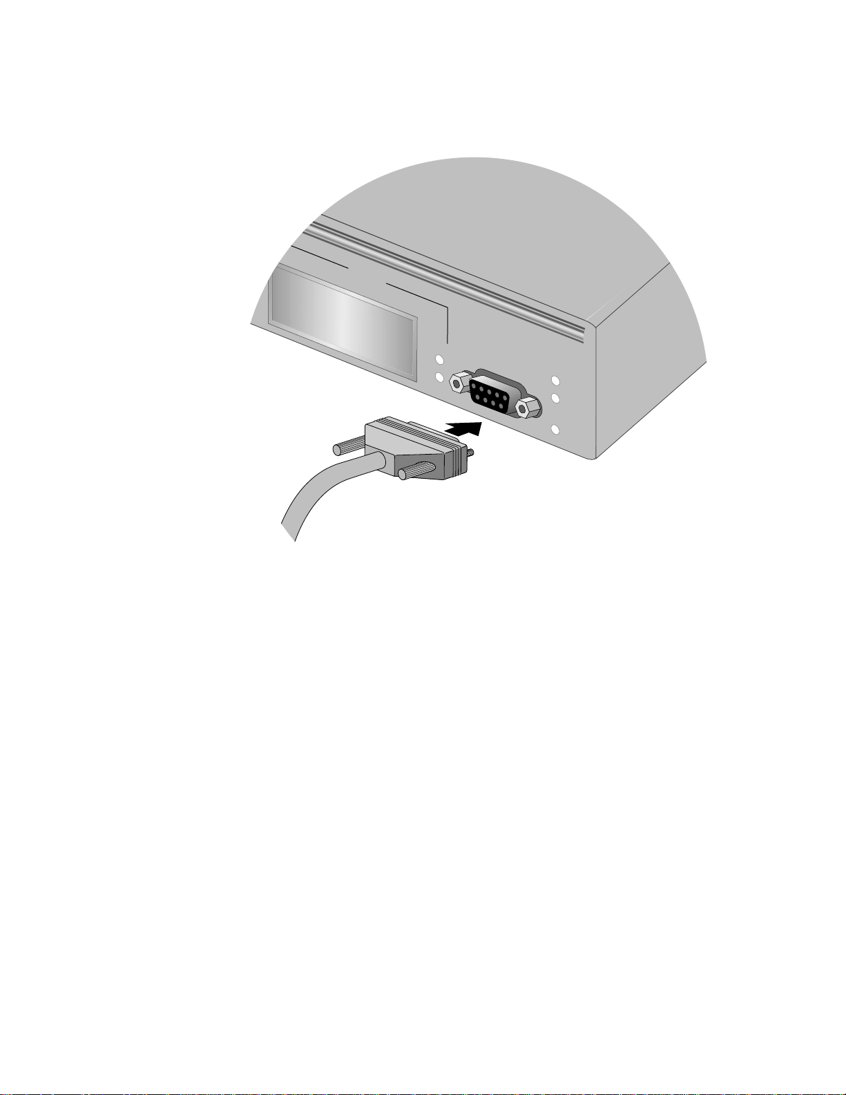
To start a local management session, perform the following procedure:
1. Connect one end of a straight-through RS232 cable with a DB-9
connector to the RS232 Terminal Port on the switch.
RS-232 TERMINAL PORT
Figure 1 Connecting a Terminal or PC to the RS232 Terminal Port
2. Connect the other end of the cable to an RS-232 port on a terminal or
PC with a terminal emulator program.
3. Configure the terminal or terminal emulator program as follows:
❑ Baud rate: 1200 bps to 115200 bps (default 9600; see Note below)
❑ Data bits: 8
❑ Parity: None
❑ Stop bits: 1
❑ Flow contro l: None
30
Page 31

AT-S39 User’s Guide
Note
The switch has an auto-detect feature on the serial port that
auomatically determines the speed of the local terminal. Activate
this feature by pressing the Return or Enter key twice on your
keyboard when you initially start the local interface or within five
seconds after powering on or resetting the switch. The switch
responds by determining the speed of the terminal and
automatically configuring the speed of the RS232 Terminal Port
accordingly. Otherwise, the switch uses a default baud rate of 9600
bits per second (bps). The switch maintains the terminal port speed
until the system is again powered on or reset. The range of the port’s
baud rate is 1200 to 115200 bps.
Note
The port settings are for a DEC VT100 or ANSI terminal, or an
equivalent terminal emulator program.
Note
During boot up, the switch displays the following prompt: Press
any key to stop image loading and go to Boot
Prompt. This message is intended for manufacturing purposes
only. (If you inadvertently display the boot prompt (=>), type boot
and press Return to start the switch.)
4. Press the Return key twice.
If prompted for a password, enter the password for the
management software. The default password for manager access
is “friend”. The default password for operator access is “operator”.
Logins and passwords are case-sensitive. For information on the
two access levels, refer to Management Access Levels on page
25. (For instructions on how to change a password, refer to
Configuring the Mana g emen t Pas swo rds on page 48.)
31
Page 32

Section II: Local or Telne t M a nagement
The Main Menu is displayed.
Allied Telesyn Ethernet Switch AT-8024GB
Login Privilege: Manager
Main Menu
1 - Port Menu
2 - VLAN Menu
3 - Spanning Tree Menu
4 - Administration Menu
5 - System Config Menu
6 - MAC Address Tables
7 - Ethernet Statistics
8 - Diagnostics
9 - Enhanced Stacking
C - Command Line Interface
Q - Quit
Figure 2 Main Menu
To select a menu item, type the corresponding letter or number.
Pressing the Esc key or typing the letter R in a submenu or menu, returns
you to the previous menu.
Please note the following:
❑ The Command Line Interface selection in the Main Menu is not
described in this manual. For instructions on this option, refer to
the AT-S39 Command Line Interface User’s Guide.
❑ If a dollar sign ($) is displayed instead of the Main Menu, the
console interface has been configured for a command line
interface management session. To display the Main Menu, type
menu and press Return.
❑ During boot up, the switch displays the following message:
Press any key to stop image loading and go to
Boot Prompt. This message is for manuf acturing purposes only.
If you do inadvertently display the boot prompt (=>), type boot
and press Return to start the switch’s software.
32
Page 33

AT-S39 User’s Guide
Enhanced
Stacking
Quitting from a
Local Session
When you start a local management session on a switch that has been
designated as the Master switch of an enhanced stack, you can manage
all the switches in the same subnet from the same management session.
This can save you the time and trouble of having to start a separate local
management session each time you want to manage a switch in your
network. It can also save you from having to go to the different wiring
closets where the switches are located.
For information on enhanced stacking and how to manage different switches from the same management session, refer to Chapter 4, Enhanced Stacking on page 57.
To quit a local session, return to the Main Menu and type Q for Quit.
You should always exit from a management session when you are
finished managing a switch. This can prevent unauthorized individuals
from making changes to a switch’s configuration should you leave your
management station unattended.
Note
You cannot operate both a local management session and a Telnet
management session on the same switch simultaneously. Failure to
properly exit from a local or Telnet management session may block
future management sessions.
33
Page 34

Section II: Local or Telne t M a nagement
Telnet Management Session
You can use the Telnet application protocol from a workstation on your
network to manage an AT-8000 Series switch. This type of management
is referred to as remote management because you do not have to be
physically close to the switch to start the session, such as with a local
management session. Any workstation on your network that has the
application protocol can be used to manage the switch.
In terms of functionally, there are almost no differences between
managing a switch locally through the RS232 Terminal Port and
remotely with the Telnet application protocol. You see the same menu
selections and have nearly the same management capabilities.
Starting a Telnet management session requires that there be at least one
AT-8000 Series switch on your network that has an IP address. The switch
with the IP address is referred to as the master switch. Once you have
started a Telnet management session on the master switch, you will
have management access to all the other AT-8000 Series switches that
reside in the same subnet.
Starting a Telnet
Management
Session
Note
Note
For background information on enhanced stacking, refer to
Enhanced Stacking Overview on page 58.
To start a Telnet management session, specify the IP address of the
master switch of the enhanced stack in the Telnet application protocol
and enter the management software password when prompted. The
default password for manager access is “friend”. The default password
for operator access is “operator”. Logins and passwords are casesensitive. For information on the two access levels, refer to
Management Access Levels on page 25. (For instructions on how to
change a password, refer to Con figuring the Managemen t Pas swo rds
on page 48.)
The Main Menu of a Telnet management session is the same menu that
you see in a local management session, shown in Figure 2 on page 32.
Nearly all the functions from a local management session are available to
you from a Telnet management session.
The menus also function the same. To make a selection, type its
corresponding number of letter. To return to a previous menu, type R or
press ESC twice.
34
Page 35

AT-S39 User’s Guide
Note
You can run only one Telnet management session on a switch at a
time. Additionally, you cannot run both a Telnet management
session and a local management session on the same switch at the
same time.
Quitting from a
Telnet
Management
Session
To end a Telnet management session, return to the Main Menu and type
Q for Quit.
35
Page 36

Chapter 3
Basic Switch Parameters
This chapter contains a variety of information and procedures. There is a
discussion on when to assign an IP address to a switch and the different
ways that you can go about it. There are also procedures for resetting
the switch, activating the original switch default settings, and more.
Sections in the chapter include:
❑ When Does a Switch Need an IP Address? on page 37
❑ Configuring an IP Address and Switch Name on page 39
❑ Activating the BOOTP and DHCP Services on page 42
❑ Configuring SNMP Communit y Strings and Trap IP Ad dresses
on page 44
❑ Resetting a Switch on page 47
❑ Configuring the AT-S39 Software Security Features on page
48
❑ Viewing the AT-S39 Version Number and Switch MAC Address
on page 52
❑ Pinging a Remote System on page 53
❑ Returning the AT-S39 Software to the Factory Defau lt Values
on page 54
❑ Configuring th e Co ns ole Startup Mode on page 55
❑ Configuring BALUN Cable Detection on page 56
36
Page 37

When Does a Switch Need an IP Address?
One of the tasks to building or expanding a network is decidin g which of
the managed switches need to be assigned unique IP addresses. The
rule used to be that a managed switch needed an IP address if you
wanted to manage it remotely, such as with the Telnet application
protocol. However, if a network contained a lot of managed switches,
having to assign each one an IP address was often cumbersome and
time consuming. It was also often difficult keeping track of all the IP
addresses.
The enhanced stacking feature of the AT-8000 Series switch simplifies all
this. With enhanced stacking, you need assign an IP address to only one
AT-8000 Series switch in each subnet in your network. The switch with
the IP address is referred to as the Master switch of the subnetwork. All
switches in the same subnet share the IP address.
Starting a local or remote management session on the Master switch
automatically gives you complete management access to all the other
switches in the same subnet.
AT-S39 User’s Guide
This feature has two primary benefits. First, it helps reduce the number
of IP addresses you have to assign to your network devices. Second, it
allows you to configure multiple switches through the same local or
remote management session.
If your network consists of multiple subnets, you must assign a unique IP
address to at least one switch in each subnet. The switch with the IP
address will be the Master switch of that subnet.
When you assign a switch an IP address, you must also assign it a subnet
mask. The switch uses the subnet mask to determine which portion of an
IP address represents the network address and which the node address.
You must also assign the switch a gateway address if there is a router
between the switch and the remote management workstation. This
gateway address is the IP address of the router through which the switch
and management station will commun icate.
Note
For further information on enhanced stacking, refer to Enhanced
Stacking Overview on page 58.
If you do not plan to remotely manage any of the AT-8000 Series
switches in your network, then you do not need to assign any of them an
IP address. The switches will operate fine without an IP address and you
will still be able to manage them completely using local management
sessions.
37
Page 38

Section II: Local and Telne t Management
How Do You
Assign an IP
Address?
Once you have decided which, if any, switches on your network need an
IP address, you have to access the AT-S39 software on the switches and
assign the addresses. There are actually two ways in which a switch can
obtain an IP address.
The first method is for you to assign the IP configuration information
manually. The procedure for this is explained in Configuring an IP
Address and Switch Name on page 39. Initially assigning an IP address
to a switch can only be done through a local management session.
The second method is for you to activate the BOOTP and DHCP services
on the switch and have the switch automatically download its IP
configuration information from a BOOTP or DHCP server on your
network. This procedure is explained in Activating the BOOTP and
DHCP Services on page 42.
38
Page 39

Configuring an IP Address and Switch Name
The procedure in this section explains how to manually assign an IP
address, subnet mask, and gateway address to the switch from a local or
Telnet management session. (If you want the switch to obtain its IP
configuration from a DHCP or BOOTP server on your network, go to the
procedure Activating the BOOTP and DHCP Services on page 42.)
This procedure also explains how to assign a name to the switch, along
with other optional information, such as the name of the administrator
responsible for maintaining the unit and the location of the switch.
To manually set a switch’s IP address, perform the following procedure:
1. From the Main Menu, type 4 to select Administration Menu.
The Administration Menu in Figure 3 is displayed.
Allied Telesyn Ethernet Switch AT-8024
Login Privilege: Manager
Administration Menu
AT-S39 User’s Guide
1 - IP Address ........ 0.0.0.0
2 - Subnet Mask ....... 0.0.0.0
3 - Default Gateway ... 0.0.0.0
4 - System Name .......
5 - Administrator .....
6 - Comments ..........
7 - Set Password ......
8 - BOOTP/DHCP ........ Disabled
9 - Reset Switch
A - Server-based Authentication
D - Downloads & Uploads
P - Ping a Remote System
R - Return to Previous Menu
Enter your selection?
Figure 3 Administration Menu
39
Page 40

Section II: Local and Telne t Management
2. Change the parameters as desired.
The parameters in the IP Parameters menu are described below:
1 - IP Address
This parameter specifies the IP address of the switch. You must
specify an IP address if you intend to remotely manage the switch
using a web browser, a Telnet utility, or an SNMP management
program, or if you want a switch to function as the Master switch
of an enhanced stack.
2 - Subnet Mask
This parameter specifies the subnet mask for the switch. You must
specify a subnet mask if you assigned an IP address to the switch.
3 - Default Gateway
This parameter specifies the default router’s IP address. This
address is required if you intend to remotely manage the switch
from a management station that is separated from the switch by
a router.
4 - System Name
This parameter specifies a name for the switch (for example, Sales
Ethernet switch). This parameter is optional.
Note
It is advisable that you assign each switch a name. The names can
help you identify the various switches when you manage them and
avoid performing a configuration procedure on the wrong switch.
5 - Administrator
This parameter specifies the name of the network administrator
responsible for managing the switch. This parameter is optional.
6 - Comments
This parameter specifies additional information about the Fast
Ethernet switch, such as its location (for example, 4th Floor wiring closet 402B). This parameter is optional.
7 - Set Password
This parameter is used to change the Manager and Operator’s
login passwords. For instructions, refer to Configuring the
Management Passwords on page 48.
8 - BOOTP/DHCP
This selection activates and deactivates the BOOTP and DHCP
services on the switch. For information on this selection, refer to
Activating th e BOOT P an d DH C P Se r vic e s on page 42.
40
Page 41

AT-S39 User’s Guide
9 - Reset Switch
This selection resets the switch.
A - Server-based Authentication
This selection is used to configure the TACACS+ and RADIUS
authentication protocols on the switch. For information on this
feature, refer to Chapter 17, TACACS+ and RADIUS Protocols
on page 191.
Downloads and Uploads
For information on this selection, refer to Chapte r 20, File
Downloads and Uploads on page 213.
R - Ping a Remote System
For information on this selection, refer to Pinging a Remote
System on page 53.
3. After you have set the parameters, type S to select Save Configuration
Changes.
Note
A change to any of the parameters in this menu, including the IP
address, subnet mask, or gateway address, are immediately
activated on a switch.
41
Page 42

Section II: Local and Telne t Management
Activating the BOOTP and DHCP Services
The BOOTP and DHCP application protocols were developed to simplify
network management. They are used to automatically assign IP
configuration information to the devices on your network, such as an IP
address, subnet mask, and a default gateway address.
An AT-8000 Series switch supports these protocols and can obtain its IP
configuration information from a BOOTP or DHCP server on your
network. If you activate this feature, the switch will seek its IP address
and other IP configuration information from a BOOTP or DHCP server on
your network whenever you reset or power ON the device.
Naturally, for this to work there must be a BOOTP or DHCP server
residing on your network and you must configure the service by
entering in the switch’s MAC address.
BOOTP and DHCP services typically allow you to specify how the IP
address is to be assigned to the switch. Choices are static and dynamic. If
you choose static, the server will always assign the same IP address to
the switch when the switch is reset or powered ON. This is the preferred
configuration. Since the BOOTP and DHCP services always assigns the
same IP address to a switch, you will always know which IP address to
use when you need to remotely manage a particular switch.
If you choose dynamic, the server will assign any unused IP address that
it has not already assigned to another device. This means that a switch
might have a different IP address each time you reset or power cycle the
device, making it difficult for you to remotely manage the unit.
Note
The BOOTP and DHCP option is disabled by default on the switch.
To activate or deactivate the BOOTP and DHCP protocols on the switch,
perform the following procedure:
1. From the Main Menu, type 4 to select Administration Menu.
The Administration in Figure 3 on page 39 is displayed.
2. Type 8 to select BOOTP/DHCP.
The following prompt is displayed:
BOOTP/DHCP (E-Enabled, D-Disabled):
3. Type E to enable BOOTP and DHCP services on the switch or D to
disable the services and press Return. The default is disabled.
4. Type S to select Save Configuration Changes.
42
Page 43

AT-S39 User’s Guide
Note
If you activated BOOTP/DHCP, the switch immediately begins to
query the network for a BOOTP or DHCP server. The switch
continues to query the network for its IP configuration until it
receives a response.
43
Page 44

Section II: Local and Telne t Management
Configuring SNMP Community Strings and Trap IP Addresses
To configure the SNMP community strings for the switch and to assign
up to four IP addresses of management stations to receive traps from
the switch, perform the following procedure:
Note
SNMP access is disabled by default. To enable SNMP access, refer to
Configuring Management Access on page 51.
1. From the Main Menu, type 5 to select System Config Menu.
The System Configuration Menu in Figure 4 is displayed.
Allied Telesyn AT-8024 Ethernet Switch
Login Privilege: Manager
System Config Menu
1 - MAC Aging Time .................... 300 seconds
2 - Switch Mode ....................... Tagged
3 - Console Disconnect Timer Interval . 10 minute(s)
4 - Web Server Status ................. Enabled
5 - SNMP Access ....................... Disabled
6 - Console Startup Mode .............. Menu
7 - BALUN Cable Detection ............. Disabled
8 - Reset to Factory Defaults
A - Advanced Configuration
R - Return to Previous Menu
Enter your selection?
Figure 4 System Configuration Menu
44
Page 45

AT-S39 User’s Guide
2. From the System Configuration Menu, type A to select Advanced
Configuration.
The Advanced Configuration menu in Figure 5 is displayed.
Allied Telesyn AT-8024 Ethernet Switch
Login Privilege: Manager
Advanced Configuration Menu
1 - IGMP Snooping Configuration
2 - Broadcast Timers Setup
3 - SNMP Configuration
R - Return to Previous Menu
Enter your selection:
Figure 5 Advanced Configuration Menu
3. From the Advanced Configuration menu, type 3 to select SNMP
Configuration. The SNMP Configuration menu in Figure 6 is
displayed.
Allied Telesyn AT-8024 Ethernet Switch
Login Privilege: Manager
SNMP Configuration
1 - GET Community .............. public
2 - SET Community .............. private
3 - Trap Community ............. public
4 - Trap Receiver 1 ............ 0.0.0.0
5 - Trap Receiver 2 ............ 0.0.0.0
6 - Trap Receiver 3 ............ 0.0.0.0
7 - Trap Receiver 4 ............ 0.0.0.0
S - Save Configuration Changes
R - Return to Previous Menu
Enter your selection:
Figure 6 SNMP Configuration Menu
45
Page 46

Section II: Local and Telne t Management
4. Adjust the parameters as desired. To change a value, type its
corresponding number and, when prompted, enter the new value.
The parameters are described below.
1 - GET Community
2 - SET Community
3- Trap Community
Use these parameters to set a switch’s SNMP community strings.
4 - Trap Receiver 1
5 - Trap Receiver 2
6 - Trap Receiver 3
7 - Trap Receiver 4
Use these selections to specify the IP addresses of up to four
management workstations on your network to receive traps from
the switch.
5. After making your changes, type S to select Save Configuration
Changes.
Changes to the SNMP parameters are immediately activated on
the switch.
46
Page 47

Resetting a Switch
To reset a switch, perform the following procedure:
1. From the Main Menu, type 4 to select Administrator Menu.
2. From the Administrator Menu, type 9 to select Reset Switch.
3. Type Y to reset the switch or N to cancel this procedure.
4. Press the Return key twice.
AT-S39 User’s Guide
The following prompt is displayed:
Do you want to proceed with the switch reboot?
[Yes/No] ->
The following prompt is displayed:
Please press <ENTER> key TWICE to proceed with the
Switch Reset...
The switch reloads its operating system, a task requiring
approximately 20 seconds to complete.
Caution
The switch will not forward traffic during the brief period required to
reload its operating software. Some data traffic may be lost.
47
Page 48

Section II: Local and Telne t Management
Configuring the AT-S39 Software Security Features
The AT-S39 software has several security features that can help prevent
unauthorized individuals from changing the parameter settings of an
AT-8000 Series switch. The security features are:
❑ Manager and Operator Passwords - The management software
has two standard, management login accounts: Manager and Operator. The Manager acount allows you to configure all switch parameters, while the Operator account only allows you to view the parameter settings. The default login for Manager access is “manager” and the password is “friend”. Both login and password for Operator access are “operator”. Logins and passwords are case-sensitive. For instructions on how to change a password, refer to Configuring the Manag e men t Pa sswo rds on page 48. (You can create additional management login accounts for the switch if your network contains a TACACS+ or RADIUS authentication protocol server. For instructions, refer to Chapter 17, TACACS+ and RADIUS Protocols on page 191.)
❑ Console Timeout - This parameter causes the management
software to automatically end a management session if it does
not detect any activity from the local or remote management
station after the specified period of time. This security feature can
prevent unauthorized individuals from using your management
station should you step away from your system while configuring
a switch. The default for the console timeout value is 10 minutes.
For instructions on how to set this security feature, refer to
Configuring Management Access on page 51.
❑ Web Access - You can disable the web browser management
feature on the switch, and so prevent individuals from managing
the switch remotely using a web browser. By default, Web access
is enabled. For instructions on how to set this security feature,
refer to Configuring Management Access on page 51.
❑ SNMP Access - You can also disable the SNMP management
feature on the switch, and so prevent individuals from managing
the switch remot ely using a SN MP management program. By
default, SNMP access is disabled. For instructions on how to set
this security feature, refer to Configuring Management Access
on page 51.
Configuring the
Management
Passwords
There are two levels of management access on an AT-8000 Series switch:
Manager and Operator. When you log in as a Manager, you can view and
configure all of a switch’s operating parameters. When you log in as an
Operator, you can only view the operating parameters; you cannot
change any values.
48
Page 49

AT-S39 User’s Guide
You log in as a Manager or an Operator by entering the appropriate
password when you start an AT-S39 management session. The default
password for Manager access is “friend”. The default password for
Operator access is “operator”. Logins and passwords are case-sensitive.
To change the Manager or Operator password, perform the following
procedure:
1. From the Main Menu, type 4 to select Administrator Menu.
2. From the Administrator Menu, type 7 to select Set Password. The
Passwords Menu in Figure 7 is displayed.
Allied Telesyn Ethernet Switch AT-8024
Login Privilege: Manager
Passwords Menu
1 - Set Manager Password
2 - Set Operator Password
R - Return to Previous Menu
Enter your selection?
Figure 7 Passwords Menu
3. Type 1 to change the Manager password or type 2 to change the
Operator password.
4. When prompted, enter the current Manager or Operator password.
5. When prompted, enter the new Manager or Operator password.
6. When prompted, re-enter the new Manager or Operator password.
Note
The password can be from 0 to 20 alphanumeric characters. Logins
and passwords are case-sensitive.
Note
The two passwords should be different. If both passwords are the
same, the management software will always assume that you wish
to log in as Manager.
49
Page 50

Section II: Local and Telne t Management
Caution
You should not use spaces or special characters, such as asterisks (*)
and exclamation points (!), in a password if you will be managing the
switch from a web browser. Many web browsers cannot handle
special characters in passwords.
50
Page 51

AT-S39 User’s Guide
Configuring
Management
Access
To configure the console timer, web access, SNMP access, and TFTP
server security features of the AT-S39 management software, perform
the following procedure:
1. From the Main Menu, type 5 to select System Config Menu.
The System Con figuration Menu Figure 4 on page 4 4 is d is play ed .
2. To configure the console timer, type 3 to select Console Disconnect
Timer Interval and, when prompted, enter a value of from 1 to 60
minutes. The default value is ten minutes.
For example, if you specify 2 minutes, the AT-S39 management
software automatically ends a management session if it does not
detect any activity from the local or remote management station
after 2 minutes.
3. To configure web browser access, type 4 to select Web Server Access
and, when prompted, type E to enable web access or D to disable
web access. The default value is enabled.
For example, if you disable web access, no one will be able to
manage the switch remotely using a web browser.
4. To configure SNMP access, type 5 to select SNMP Access and, when
prompted, type E to enable SNMP management access or D to
disable it. The default value is disabled.
For example, if you disable SNMP access, no one will be able to
manage the switch remotely using an SNMP management
program.
5. After you have made the desired changes, type S to select Save
Configuration Changes.
Your changes are immediately activated on the switch.
51
Page 52

Section II: Local and Telne t Management
Viewing the AT-S39 Version Number and Switch MAC Address
The procedure in this section displays the following switch information:
❑ AT-S39 version number
❑ Bootloader version number
❑ Serial number
❑ MAC Address
To display the information, type 8 to select Diagnostics from the Main
Menu. The Diagnostics menu in Figure 8 is displayed.
Allied Telesyn Ethernet Switch AT-8024
Login Privilege: Manager
Diagnostics
1 - Application Software Version .... AT-S39 v3.1.0
2 - Application Software Build Date . Mar 14 2003 19:32:40
3 - Bootloader Version .............. ATS39_LOADER v2.0.1
4 - Bootloader Build Date ........... Jul 29 2002 16:37:14
5 - Serial Number ................... S05248014600028
6 - MAC Address ..................... 00:30:84:52:03:80
7 - Uplink Information
R - Return to Previous Menu
Enter your selection?
Figure 8 Diagnostics Men u
The information displayed in selections 1 through 6 in this menu cannot
be changed. For information on option 7, refer to Displaying Uplink
Information on page 73.
52
Page 53

Pinging a Remote System
You can instruct the switch to ping a remote device on your network.
This procedure is useful in determining whether a valid link exists
between the switch and another device.
To ping a network device, perform the following procedure:
1. From the Main Menu, type 4 to select Administration Menu.
2. From the Administration Menu, type P to select Ping a Remote
System.
The following prompt is displayed:
Please enter an IP address ->
3. Enter the IP address of the end node you want the switch to ping and
press Return.
The results of the ping command are displayed on the screen. To
stop the ping, press any key.
AT-S39 User’s Guide
53
Page 54

Section II: Local and Telne t Management
Returning the AT-S39 Software to the Factory Default Values
The procedure in this section returns all AT-S39 software parameters to
their default values. This procedure also deletes any VLANs that you
have created on the switch.
Note
The AT-S39 software default values can be found in Appendix A,
AT-S39 Default Settings on page 312.
To return the AT-S39 management software to its default settings,
perform the following procedure:
1. From the Main Menu, type 5 to select System Config Menu.
2. From the System Configuration Menu, type 8 to select Reset to
Factory Defaults.
The following prompt is displayed:
Are you sure you want to reset to Factory Defaults?
[Yes/No] ->
3. Type Y for yes or N for no.
The following prompt is displayed:
Do you want to reset IP, Subnet and Gateway as well?
[Yes/No] ->
4. If you type Y for yes, all switch parameters including the IP address,
subnet mask, and gateway address are changed to their default
values. If you type N for no, all switch parameters excluding the IP
address, subnet mask, and gateway address are changed to their
default values.
The following prompt is displayed:
The Factory Defaults take effect only after the
Switch reboots.
Do you want to Reboot the Switch now? [Yes/No] ->
5. Type Y to reset the switch.
The operating parameters are returned to their default values and
the switch is reset.
Caution
The switch will not forward traffic during the brief period required to
reload its operating software. Some data traffic may be lost.
54
Page 55

Configuring the Console Startup Mode
You can configure the AT-S39 software to display either the Main Menu
or the command line interface prompt ($) whenever you start a local
management session. The default is the Main Menu.
To change the console startup mode, perform the following procedure:
1. From the Main Menu, type 5 to select System Config Menu.
2. From the System Configuration Menu, type 6 to select Console
Startup Mode.
The following prompt is displayed:
Enter Console Mode (M-Menu, C-CLI):
3. Type M if you want a local management session to always start with
the Main Menu, or C if you want it to display the command line
interface prompt.
AT-S39 User’s Guide
A change to the console startup mode takes effect the next time
you start a local management session.
55
Page 56

Section II: Local and Telne t Management
Configuring BALUN Cable Detection
You can configure the AT-S39 software to detect loopback cables for all
10/100/1000 copper ports. When a loopback cable is detected, the port
is set to MANUAL/10/HDX/MDIX and a message is displayed on the
console. When the loopback cable is replaced with a good cable, the
original port settings are restored.
To configure the switch to enable or disable balun cable detection,
perform the following procedure:
1. From the Main Menu, type 5 to select System Config Menu.
2. From the System Configuration Menu, type 7 to select BALUN Cable
Detection. The following prompt is displayed:
Enter BALUN Cable Detection Status (E-Enabled, D-Disabled) :
3. Select E to enable cable detection or select D to disable cable
detection.
56
Page 57

Chapter 4
Enhanced Stacking
This chapter explains the enhanced stacking feature. The sections in this
chapter include:
❑ Enhanced Stacking Overview on page 58
❑ Setting a Switch’s Enhanced Stacking Status on page 61
❑ Selecting a Switch in an Enhanced Stack on page 63
Note
When managing the remote/telnet interface do not reset the IP
address to null. This will cause disconnection without local
management intervention.
57
Page 58

Section II: Local and Telne t Management
Enhanced Stacking Overview
The enhanced stacking feature can make it easier for you to manage the
AT-8000 Series switches in your network. It offers the following benefits:
❑ You can manage up to 24 switches from one local or remote
management session. This eliminates the need of having to
initiate a separate management session for each switch in your
network.
❑ The switches can share the same IP address. This reduces the
number of IP addresses that you need to assign to your network
devices for remote management.
❑ Remotely managing a new swit ch in your network is simplified.
You simply connect it to your network. Once connected to the
network, you can begin to manage it immediately from any
workstation in your network.
Guidelines There are a few guidelines to keep in mind when implementing
enhanced stacking for your network:
❑ Each subnet in your network can only have one enhanced stack.
You cannot have multiple enhanced stacks in a subnet.
❑ Each subnet must have at least one master switch.
❑ You must assign the master switch an IP address and subnet mask.
❑ You must change the master switch’s stacking status to Master.
There are three basic steps to implementing this feature on your
network:
1. You must select a switch in your network to function as the master
switch of the stack.
You can select any AT-8000 Series switch to act as the master
switch of an enhanced stack. For networks that consist of more
than one subnet, there must be at least one master switch in each
subnet.
It is recommended that each subnet have two master switches.
That way, should you remove one of the master switches from the
network, such as for maintenance, you all still be able to remotely
manage the switches in the subnet using the other master switch.
58
Page 59

AT-S39 User’s Guide
2. You must assign the master switch an IP address and subnet mask.
A master switch must have an IP address and subnet mask. The
other switches in an enhanced stack, referred to as slave switches,
do not.
If an enhanced stack will have more than one master switch, you
must assign each master switch a unique IP address.
Note
You can set the IP address manually or activate the BOOTP and
DHCP services on a master switch and have the master switch
obtain its IP information from a BOOTP or DHCP server on your
network. Initially assigning an IP address or activating the BOOTP
and DHCP services can only be performed through a local
management session.
For instructions on how to set the IP address manually, refer to
Configuring an IP Address and Switch Name on page 39. For
instructions on activating the BOOTP and DHCP services, refer to
Activating the BOOTP and DHCP Services on page 42.
3. Change the enhanced stacking status of the master switch to Master.
This is explained in the procedure Setting a Switch’s Enhanced
Stacking Status on page 61.
Note
By default, the switches are sorted in the menu by MAC address. You
can sort the switche s by name as well. This is accompli shed by
selecting S for Sort Switches in New Order.
59
Page 60
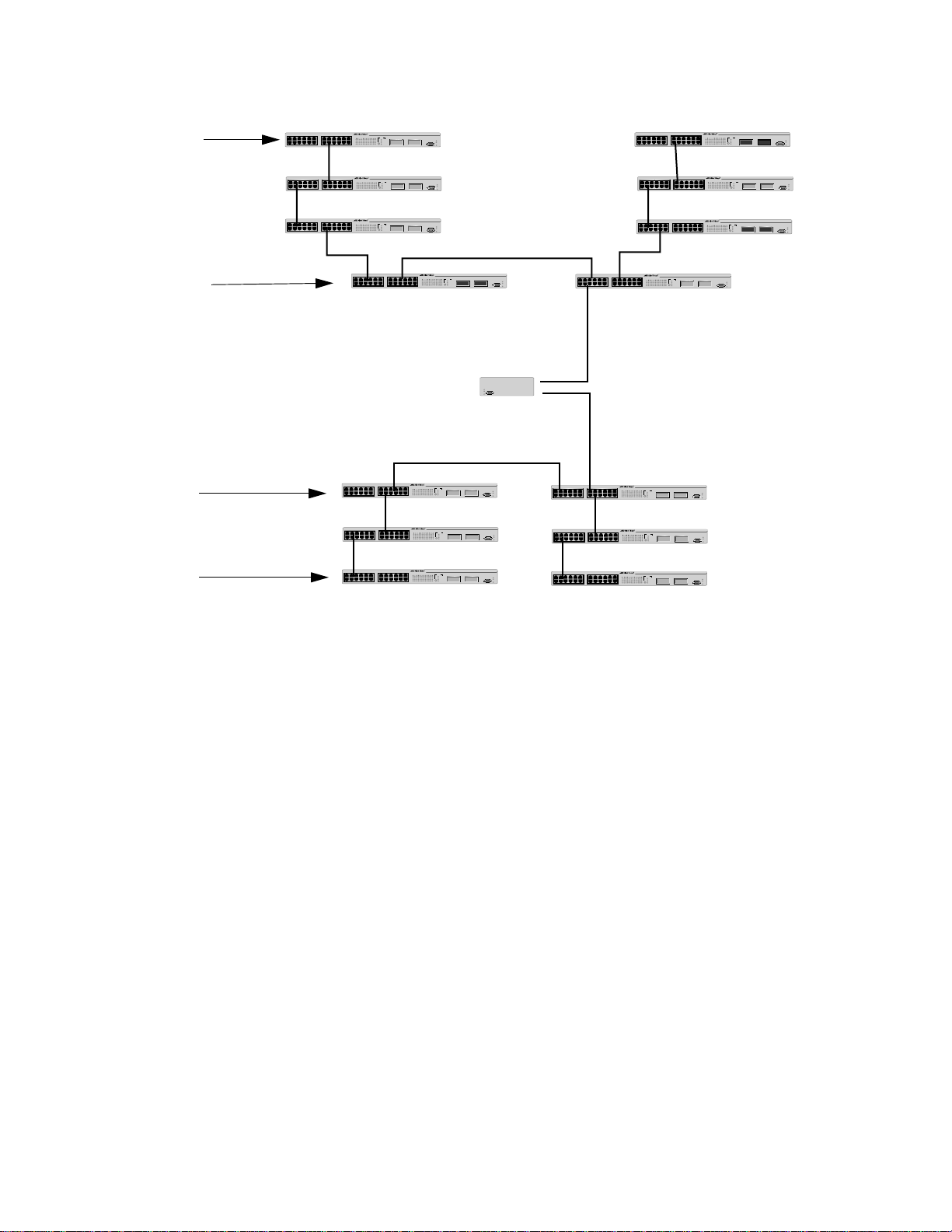
Section II: Local and Telne t Management
Master 1
IP Address
149.32.11.22
Master 2
IP Address
149.32.11.16
Master 1
IP Address
149.32.09.18
Figure 9 is an example of the enhanced stacking feature.
Subnet A
RS-232 TERMINAL PORT
FAULT
Router
MASTER
PWR
Subnet B
Master 2
IP Address
149.32.09.24
Figure 9 Enhanced Stacking Example
The example consists of a network of two subnets interconnected with a
router. Two switches in each subnet have been selected as the master
switches of their respective subnets, and each has been assigned a
unique IP address.
To manage the switches of a subnet, you could start a local management
session or a remote Telnet management session with one of the master
switches in the subnet. You would then have management access to all
the AT-8000 Series switches in the same subnet.
60
Page 61

Setting a Switch’s Enhanced Stacking Status
The enhanced stacking status of the switch can be master switch, slave
switch, or unavailable. Each status is described below:
❑ Master switch - A master switch of a stack can be used to manage
all the other AT-8000 Series switches in a subnet. Once you
establish a local or remote management session with the Master
switch, you can access and manage all the switches in the subnet.
A master switch must have a unique IP address. You can
manually assign a master switch an IP address or activate the
BOOTP and DHCP services on the switch.
❑ Slave switch - A slave switch can be remotely managed through a
master switch. It does not need an IP address or subnet mask.
❑ Unavailable - A switch with an unavailable stacking status cannot
be remotely managed through a master switch. A switch with this
designation can be managed locally. To be managed remotely, a
switch with an unavailable stacking status must be assigned a
unique IP address.
AT-S39 User’s Guide
Note
The default setting for a switch is Slave.
To adjust a switch’s enhanced stacking status, perform the following
procedure:
1. From the Main Menu, type 9 to select Enhanced Stacking.
The Enhanced Stacking menu in Figure 10 is displayed.
Allied Telesyn Ethernet Switch AT-8024
Login Privilege: Manager
Enhanced Stacking
1 - Switch State-(M)aster/(S)lave/(U)navailable.... Master
2 - Stacking Services
S - Save Configuration Changes
R - Return to Previous Menu
Enter your selection?
Figure 10 Enhanced Stacking Menu
61
Page 62

Section II: Local and Telne t Management
The menu displays the current status of the switch at the end of
selection “1 - Switch State.” For example, the switch’s current
status in the figure above is Master.
Note
The “2 - Stacking Services” selection in th e menu is avai lable only on
master switches.
2. To change a switch’s stacking status, type 1 to select Switch State.
The following prompt is displayed.
Enter new setup (M/S/U) ->
3. Type M to change the switch to a master switch, S to make it a slave
switch, or U to make the switch unavailable. Press Return.
4. Type S to select Save Configuration Changes.
A change to the status is immediately activated on the switch.
62
Page 63

Selecting a Switch in an Enhanced Stack
The first thing that you should do before performing any procedure on a
switch in an enhanced stack is check to be sure that you are performing
it on the correct switch. If you assigned system names to your switches,
this should be easy. The name of the switch being managed is always
displayed at the top of every management menu.
When you start a management session on the Master switch of a subnet,
you are by default addressing that particular switch. The management
tasks that you perform effect only the master switch.
To manage a slave switch or another Master switch in the subnet, you
need to select it from the management software.
To select a switch to manage in an enhanced stack, perform the
following procedure:
1. From the Main Menu, type 9 to select Enhanced Stacking.
AT-S39 User’s Guide
2. From the Enhanced Stacking menu, type 2 to select Stacking Services.
The menu in Figure 11 is displayed.
Allied Telesyn Ethernet Switch AT-8024GB
Sales Switch
Login Privilege: Manager
Stacking Services
Switch Software Switch
Num MAC Address Name Mode Version Model
-------------------------------------------------------------
G - Get/Refresh List of Switches
S - Sort Switches in New Order
A - Access Switch
I - Image Download to Remote Switches
C - Config Download to Remote Switches
B - Boot Loader Download to Remote Switches
R - Return to Previous Menu
Enter your selection?
Figure 11 Stacking Services M enu
63
Page 64

Section II: Local and Telne t Management
3. Type G to select Get/Refresh List of Switches.
The Master switch polls the network for all slave and Master
switches in the subnet and displays a list of the switches in the
Stacking Services menu.
Note
The Master switch on which you started the management session is
not included in the list, nor are any switches with an enhanced
stacking status of Unavailable.
Note
The selections I, C, and B for downloading image and bootloader
files are explained in Chapter 20, File Downloads and Uploads on
page 213.
By default, the switches are sorted in the menu by MAC address.
You can sort the switches by name as well. This is accomplished
with the selection S - Sort Switches in New Order.
Returning to
the Master
Switch
4. To manage a different switch in an enhanced stack, type A to select
Access Switch.
A prompt similar to the following is displayed:
Enter the switch number -> [1 to 24}
5. Type the number of the switch in the list you want to manage.
A prompt is displayed if the switch has been assigned a password.
6. Enter the switch’s password and press Return.
The default password for manager access is “friend”. The default
password for operator access i s “operator”. Logins and passwords
are case-sensitive.
The Main Menu of the selected switch is displayed. You now can
manage the switch. Any management tasks you perform effect
only the selected switch.
When you have finished managing a slave switch and want to manage
another switch in the subnet, return to the Main Menu of the slave
switch and type Q for Quit. This returns you to the Stacking Services
menu. Once you see that menu, you are again addressing the Master
switch from which you started the management session.
You can either select another switch in the list to manage or, if you want
to manage the Master switch, return to the master switch’s Main Menu
by typing R twice.
64
Page 65

Chapter 5
Port Parameters
The chapter contains procedures for viewing and changing the
parameter settings for the individual ports on a switch.
This chapter contains the following procedures:
❑ Displaying Port Status on page 66
❑ Configuring Port Parameters on page 69
❑ Displaying Uplink Information on page 73
65
Page 66

Section II: Local and Telne t Management
Displaying Port Status
To display the status of the ports on the switch, perform the following
procedure:
1. From the Main Menu, type 1 to select Port Menu.
The Port Menu in Figure 12 is displayed.
Login Privilege: Manager
1 - Port Configuration
2 - Port Mirroring
3 - Port Trunking
4 - Port Status
5 - Port Security
6 - Port Access Control
S - Save Configuration Changes
R - Return to Previous Menu
Allied Telesyn Ethernet Switch AT-8024
Port Menu
Enter your selection?
Figure 12 Port Menu
2. From the Port Menu, type 4 to select Port Status.
66
Page 67

AT-S39 User’s Guide
The Port Status window is displayed (see Figure 13).
Allied Telesyn Ethernet Switch AT-8024
Login Privilege: Manager
Port Status
Prt Link Neg MDIO Spd Dplx PVID VlanID Flow State
--------------------------------------------------------------------001 Up Auto MDI 10 Half 00001 00001 Disabled Forwarding
002 Up Auto MDI 100 Full 00001 00001 Disabled Forwarding
003 Up Auto MDI 100 Full 00001 00001 Disabled Forwarding
004 Up Auto MDI 100 Full 00001 00001 Disabled Forwarding
005 Up Auto MDI 10 Half 00001 00001 Disabled Forwarding
006 Up Auto MDI 100 Full 00001 00001 Disabled Forwarding
007 Up Auto MDI 100 Full 00001 00001 Disabled Forwarding
008 Up Auto MDI 10 Half 00001 00001 Disabled Forwarding
N - Next Page
U - Update Display
R - Return to Previous Menu
Enter your selection?
Figure 13 Port Status Window
The information in this window is for viewing purposes only. The
columns in the window are described below:
Prt
The port number.
Link
The status of the link between the port and the end node
connected to the port. Possible values are:
Up - indicates that a valid link exists between the port and the end
node.
Down - indicates that the port and the end node have not
established a valid link.
Neg
The status of Auto-Negotiation on the port. Possible values are:
Auto - Indicates that the port is using Auto-Negotiation to set
operating speed and duplex mode.
Manual - Indicates that the operating speed and duplex mode
have been set manually.
67
Page 68

Section II: Local and Telne t Management
MDIO
The operating configuration of the port. Possible values are Auto,
MDI, MDI-X. The status Auto indicates that the port is
automatically determining the appropriate MDI or MDI-X setting.
Spd
The operating speed of the port. Possible values are:
10 - 10 Mbps
100 - 100 Mbps
1000 - 1000 Mbps (AT-8024GB switch only)
Dplx
The duplex mode of the port. Possible values are half-duplex and
full-duplex.
PVID
The port VLAN identifier currently assigned to the port.
VlanID
The VLAN identifier of the VLAN in which the port is an untagged
member. This column will not include the VIDs of the VLANs
where the port is a tagged member.
Flow
The flow control setting for the port. Possible values are:
None - No flow control on the port.
Transmit - Flow control only as packets are being transmitted out
the port.
Receive - Flow control only on as packets are being received on
the port.
Both - Flow control for both packets entering and leaving the port.
State
The current operating status of the port. Possible values are:
Forwarding - The port is sending and receiving Ethernet frames.
Disabled - The port has been manually disabled.
68
Page 69

Configuring Port Parameters
To configure the parameter settings for a port on the switch, perform the
following procedure:
1. From the Main Menu, type 1 to select Port Menu.
2. From the Port Menu, type 1 to select Port Configuration.
The following prompt is displayed:
Enter Ports List ->
3. Enter the number of the port you want to configure and press Return.
To configure a range of ports, enter the first port of the range.
The following prompt is displayed:
Ending Port to Configure [1 to 24] ->
4. To configure only one port, enter the same port number as you
entered in Step 3 and press Return. To configure a range of ports,
enter the last port number in the range. The Port Configuration menu
in Figure 14 is displayed.
AT-S39 User’s Guide
Allied Telesyn Ethernet Switch AT-8024
Login Privilege: Manager
Port Configuration
Configuring Ports 4
0 - Status ............ Forwarding
1 - Negotiation ....... Auto
4 - Flow Control ...... None
5 - Advertise 10FDX ... Yes
6 - Advertise 10HDX ... Yes
7 - Advertise 100FDX .. Yes
8 - Advertise 100HDX .. Yes
M - MDI/MDIX Mode ..... Auto
B - Broadcast Control . No Broadcast Control
S - Save Configuration changes
F - Force Renegotiation
X - Reset Port
R - Return to Previous Menu
Enter your selection?
Figure 14 Port Configuration Menu
69
Page 70

Section II: Local and Telne t Management
Note
The example Port Configuration menu in the figure above is for a
10/100 Mbps twisted pair port. The menu for a fiber optic port, a
GBIC module, or a stacking module will contain a subset of the
parameters.
5. Adjust the port parameters as desired. You adjust a parameter by
typing its number. This toggles the parameter through its possible
settings. The parameters are described below.
0 - Status
You use this selection to enable or disable a port. When disabled,
a port will not receive or transmit frames.
You might want to disable a port and prevent packets from being
forwarded if a problem occurs with the node or cable connected
to the port. Once the problem has been fixed, you can enable the
port again to resume normal operation. You can also disable an
unused port to secure it from unauthorized connections.
Possible settings are:
Forwarding - The port will receive and forward packets. This is the
default setting.
Disabled - The port will not receive or forward packets.
1 - Negotiation
You use this selection to configure a port for Auto-Negotiation or
to manually set a port’s speed and duplex mode.
If you select Auto for Auto-Negotiation, which is the default, the
switch will set both speed and duplex mode for the port
automatically.
If you select Manual, two additional selections are displayed in the
menu:
2 - Speed .............. 0100
3 - Duplex ..............Full-Duplex
You use these two selections to set the port’s speed and duplex
mode. The possible settings for the 2 - Speed selection are:
0010 - 10 Mbps
0100 - 100 Mbps
1000 - 1000 Mbps (AT-8024GB switch only)
The possible settings for 3 - Duplex are Full-duplex and Half-
duplex.
70
Page 71

AT-S39 User’s Guide
Flow Control
Flow control applies only to ports operating in full-duplex mode.
The switch uses a special pause packet to stop the end node from
sending frames. The pause packet notifies the end node to stop
transmitting for a specified period of time.
Possible settings are:
None - No flow control on the port.
Transmit - Flow control only as packets are being transmitted out
the port.
Receive - Flow control only on as packets are being received on
the port.
Both - Flow control for both packets entering and leaving the port.
5 - Advertise 10FDX
6 - Advertise 10HDX
7 - Advertise 100FDX
8 - Advertise 100HDX
These selections are used for ports configured for AutoNegotiation. During Auto-Negotiation, a switch port determines
the appropriate speed and duplex mode by advertising its
capabilities to the end node connected to it.
By default, a switch port will advertise its full capabilities, which in
the case of a port on an AT-8000 Series switch are 10 or 100 Mbps
speed and half- or full-duplex mode.
You can use these four selections to limit the capabilities a switch
port will advertise during Auto-Negotiation. For example, if you
set the selection 8 - Advertise 100HDX to No, the switch port will
not advertise that it is capable of 100 Mbps, half-duplex operation.
Note
In most network environments you should leave all AutoNegotiation advertisements activated, which is the default setting.
M - MDI/MDIX Mode
Use this selection to set the wiring configuration of the port. If you
set this to Auto, which is the default setting, the port will configure
itself automatically according to the end node connected to it.
If desired, you can set the wiring configuration manually by
selecting either MDI or MDIX.
Note
The Auto setting is not available if you set a port’s speed and duplex
mode manually.
71
Page 72

Section II: Local and Telne t Management
B - Broadcast Control
For background information on this selection and instructions on
how to set the option, refer to Broadcast Storm Control
Overview on page 186 and Configuring the Maximum
Broadcast Frame Count on page 190 .
6. Once you have set the port parameters, type S to select Save
Configuration Changes.
Configuration changes are immediately activated on a port.
The Port configuration menu features a Reset Port selection. You can use
this option to reset the selected port. This can prove useful in situations
where a port is experiencing a problem establishing a valid connection
to the end node.
The menu also has a Force Renegotiation selection, which, when
selected, prompts the port to Auto-Negotiate with the end node. This
can be helpful if you believe that a port and end node are not operating
at the same speed and duplex mode.
72
Page 73

Displaying Uplink Information
The AT-S39 management software can display basic manufacturer
information about a GBIC module in an AT-8024GB switch or the fiber
optic ports in an AT-8026FC switch.
To display uplink information, perform the following procedur e:
1. From the Main Menu, type 8 to select Diagnostics.
2. From the Diagnostics menu, type 7 to select Uplink Information.
The GBIC Information menu in Figure 15 is displayed.
Allied Telesyn Ethernet Switch AT-8024
Login Privilege: Manager
1 - Uplink Information
R - Return to Previous Menu
AT-S39 User’s Guide
Uplink Information Menu
Enter your selection?
Figure 15 Uplink Information Menu
3. Type 1 to select Uplink Information.
The following prompt is displayed:
Enter Uplink Port number -> [25 to 26]
4. Type either 25 or 26; these are the port numbers for GBIC modules in
an AT-8024GB switch. Press Return.
73
Page 74

Section II: Local and Telne t Management
Allied Telesyn AT-8024GB Ethernet Switch
Login Privilege: Manager
Port Number ................... 25
Type of Serial Tranceiver ..... Unknown
Extended Serial Tranceiver .... Module Not Defined
Connector Type ................ Unknown
Elect/Opt Tranceiver ..........
Serial Encoding ............... Unspecified
Nominal bit rate(100Mbits/s) .. 0
Length 9/125 mm Fib. (k) ...... 0
The management software displays a menu containing basic
information about the GBIC module. Figure 16 is an example of
the menu.
Uplink Information Menu
Length 9/125 um Fib. (100m) ... 0
Length 50/125 um Fib. (10m) ... 0
Length 62.5/125 um Fib. (10m) . 0
N - Next Page
R - Return to Previous Menu
Enter your selection?
Figure 16 GBIC Information Menu
The information in the menu cannot be changed and is for
viewing purposes only.
74
Page 75

Chapter 6
Port Security
This chapter contains the procedures for setting port security. The
sections in this chapter include:
❑ Port Security Overview on page 76
❑ Configuring Port Security on page 78
❑ Configuring the Limited Security Mode on page 80
Note
Port security does not apply to ports on GBIC modules in an
AT-8024GB switch.
Note
Port security can only be set through a local management session,
You cannot set port security from a Telnet, Web, or SNMP
management session.
75
Page 76

Section II: Local and Telne t Management
Port Security Overview
The port security feature can enhance the security of your network. You
can use the feature to control the number of MAC addresses learned on
the ports, and so control the number of network devices that can
forward frames through the switch.
There are four levels of port security. Only one security level can be
active on a switch at a time.
Automatic
This operating mode disables port security. The switch learns and adds
addresses to its dynamic MAC address table as it receives frames on the
ports. The switch continues to learn MAC addresses so long as there is
space in the MAC address table and deletes inactive MAC addresses.
Note
The Automatic security mode is the default security level for the
switch.
Limited
You can use this security level to manually specify a maximum number
of dynamic MAC addresses each port on the switch can learn. Once a
port has learned its maximum limit, it discards frames that ingress the
port with source MAC addresses not already stored in the MAC address
table.
Once this mode is activated, the switch deletes all MAC addresses in the
dynamic MAC address table and immediately begins learning new
addresses, adding them to the dynamic MAC address table for each port
until it reaches the port’s maximum limit.
The MAC aging time is disabled under this security level. Once a dynamic
MAC address has been learned on a port and added to the MAC address
table, it remains in the table and is never purged, even when the end
node is inactive.
Note
Static MAC addresses are retained by the switch and are not
included in the count of maximum addresses that can be learned by
a port. You can continue to add static MAC addresses to a port even
if the port has already learned its maximum number of dynamic
MAC addresses.
76
Page 77

AT-S39 User’s Guide
Secure
This security level instructs the switch to forward frames based solely on
static MAC addresses. When this security level is activated, the switch
deletes all dynamic MAC addresses and disables the MAC address table
so that no new addresses can be learned.
The switch also deletes any addresses in the static MAC address table.
Once you have activated this security level, you must enter the static
MAC addresses of the nodes whose frames the switch should forward.
The switch will forward frames only from those nodes whose MAC
addresses you enter in the static MAC address table. Any node whose
MAC address is not in the static MAC address table will not be able to
send frames through the switch.
Lock All Ports
This security level causes the switch to immediately stop learning new
dynamic MAC addresses. The switch forwards frames based on the
dynamic MAC addresses that it has already learned and any static MAC
addresses that the network administrator has entered.
The MAC aging time is disabled in this security level; no dynamic MAC
addresses are deleted from the MAC address table, even those
belonging to inactive end nodes.
Note
For background information on MAC addresses and aging time ,
refer to MAC Address Over view on page 162.
77
Page 78

Section II: Local and Telne t Management
Configuring Port Security
Note
Port security can only be set through a local management session.
You cannot set port security from a Telnet management session or
from a web browser management session.
To set a switch’s port security level, perform the following procedure:
1. From the Main Menu, type 1 to select Port Menu.
2. From the Port Menu, type 5 to select Port Security.
The Port Security menu in Figure 17 is displayed.
Allied Telesyn Ethernet Switch AT-8024
Login Privilege: Manager
Port Security
1 - Configure Port Security Mode ....... AUTOMATIC
2 - Configure Limited Mode Parameters
S - Save Configuration changes
R - Return to Previous Menu
Enter your selection?
Figure 17 Port Security Menu
3. Type 1 to select Configure Port Security Mode.
The following prompt is displayed:
Enter new mode (A-Automatic, L-Limited, S-Secured, KlocKed) :
4. Select the desired security level by typing the corresponding letter:
❑ To disable port security on the switch, type A to select A u to mat i c
mode. A switch operating in Automatic mode does not restrict the
number of MAC addresses learned by the ports. The switch
continues to learn addresses so long as there is available space in
the MAC address table. This is the default setting.
❑ To specify a maximum number of MAC addresses each port can
learn, type L to select Limited mode. To specify the limits, perform
the procedure in Configuring the Limited Security Mode on
78
Page 79

AT-S39 User’s Guide
page 80.
❑ To forward frames based solely on static MAC addresses, type S to
select the Secured mode. After activating this security mode, you
must enter the static MAC addresses of the nodes with frames the
switch is to forward. For instructions on how to add static MAC
addresses, refer to Adding Static and Mu lticast MAC Addre sses
on page 171.
❑ To stop the switc h from learning new dynamic MAC addresses
and have it forward frames based only on static MAC addresses
and on those dynamic addresses that it has already learned, type
K to select Lock all the ports now.
Note
Only one security level can be active on a switch at a time.
A change to the security level is immediately activated on the
switch.
79
Page 80

Section II: Local and Telne t Management
Configuring the Limited Security Mode
The Limited security mode lets you set a maximum number of dynamic
MAC addresses each port on a switch can learn. When you activate this
security level, the switch deletes all MAC addresses in the dynamic MAC
address table and immediately begins to learn new addresses as frames
are received on the ports. Once the maximum number of MAC addresses
have been learned by a port, frames with new source MAC addresses are
discarded and are not forwarded.
You can assign the same limit to all ports or different limits to different
ports.
Static MAC addresses are not deleted from the static MAC address table.
Static MAC addresses are not included in the count of the maximum
MAC addresses a port can learn. You can continue to add static MAC
addresses even after a port has learned its maximum number of dynamic
MAC addresses.
To configure Limited security mode, perform the following procedure:
1. From the Main Menu, type 1 to select Port Menu.
2. From the Port Menu, type 5 to select Port Security.
The Port Security menu in Figure 17 on page 78 is displayed.
3. From the Port Security menu, type 2 to select Configure Limited
Mode Parameters.
The Limited Security Mode menu in Figure 18 is displayed.
Allied Telesyn Ethernet Switch AT-8024
Login Privilege: Manager
Port Security Limited-Mode Menu
1 - Display MAC Limits
2 - Configure Limited Mode Parameters
R - Return to Previous Menu
Enter your selection?
Figure 18 Limited Security Mode Menu
80
Page 81

AT-S39 User’s Guide
4. Type 2 to select Configure Limited Mode Parameters.
The following prompt is displayed:
Enter ports list:
5. Enter the port(s) where you want to specify a new MAC address limit.
You can specify the ports individually (e.g., 1,4), as a range (e.g., 4-7),
or both (e.g., 2-7,11,15).
The following prompt is displayed:
Enter new MAC limit -> [1 to 150] ->
6. Enter the maximum number of dynamic MAC addresses you want the
port to be able to learn and press Return. The range is 1 to 150
addresses. The default is 100.
7. Repeat this procedure starting with Step 4 to specify MAC address
limits on other ports.
8. Type S to select Save Configuration Changes.
9. Type 1 to select Display MAC Limits.
The current MAC address limits for all ports are displayed.
10. Examine the MAC limits. Check to be sure that they are correct. If you
assigned different values to different ports, be sure that the different
values apply to the correct ports. If necessary, repeat this procedure
to change any MAC address limits.
81
Page 82

Chapter 7
Port Trunking
This chapter contains the procedures for creating and deleting port
trunks. Sections in the chapter include:
❑ Port Trunking Overview on page 83
❑ Creating a Port Trunk on page 89
❑ Deleting a Port Trunk on page 91
82
Page 83

Port Trunking Overview
Port trunking is an economical way for you to increase the bandwidth
between two Ethernet switches. A port trunk is 2, 3, or 4 ports that have
been grouped together to function as one logical path. A port trunk
increases the bandwidth between switches and is useful in situations
where a single physical data link between switches is insufficient to
handle the traffic load.
A port trunk always sends packets from a particular source to a particular
destination over the same link within the trunk. A single link is
designated for flooding broadcasts and packets of unknown des tination.
The example in Figure 19 consists of a port trunk of four data links
between two AT-8024 switches.
AT-S39 User’s Guide
AT-8024
10Base-T/100Base-TX Fast Ethernet Switch
Link
Mode
Link
Mode
MODE
COL
100
FULL
ACT
AT-8024
10Base-T/100Base-TX Fast Ethernet Switch
Link
Mode
Link
Mode
MODE
COL
100
FULL
ACT
RS-232 TERMINAL PORT
FAULT
MASTER
PWR
Figure 19 Port Trunk Example
Observe the following guidelines when creating a port trunk:
❑ An AT-8000 Series switch can support only one port trunk at a
time.
❑ A port trunk can consist of 2, 3, or 4 ports.
❑ The ports of a port trunk must be of the same medium type. For
example, they can be all twisted pair ports or all fiber optic ports.
RS-232 TERMINAL PORT
FAULT
MASTER
PWR
❑ The speed, duplex mode, and flow control settings must be the
same for all the ports in a trunk.
❑ The ports of a port trunk must be members of the same VLAN. A
port trunk cannot consist of ports from different VLANs.
83
Page 84

❑ When cabling a trunk, the order of the connections should be
maintained on both nodes. The lowest numbered port in a trunk
on the switch should be connected to the lowest numbered port
of the trunk on the other device, the next lowest numbered port
on the switch should be connected to the next lowest numbered
port on the other device, and so on.
For example, assume that you are connecting a trunk between
two AT-8024 switches. On the first AT-8024 switch you had
chosen ports 12, 13, 14, 15 for the trunk. On the second AT8024 switch you had chosen ports 21, 22, 23, and 24. To
maintain the order of the port connections, you would
connect port 12 on the first AT-8024 switch to port 21 on the
second AT-8024, port 13 to port 22, and so on.
❑ You can create a port trunk of optional GBIC modules installed in
Port 25 and Port 26 of an AT-8024GB switch.
❑ You can create a port trunk of the fiber optic ports in an
AT-8026FC switch.
❑ You can create a port trunk of the ports in two expansion modules
in an AT-8016F switch, providing that the ports are of the same
medium type and have the same operating specifications.
Load
Distribution
Methods
There are two steps to creating a port trunk. The first is to identify the
ports on the switch that are to function as the port trunk. The second is
to select a load distribution method. This second step is important
because unless you select the correct distribution method for your
configuration, the switch might not evenly distribute the load across all
the links of a trunk. Naturally, this could greatly diminish the value and
purpose of the port trunk.
The AT-S39 management software offers two load distribution methods.
They are:
❑ Source Address (SA) Trunking
❑ Source Address / Destination Address (SA/DA) Trunking
Let’s first take a look at the SA method. When a switch receives a packet
from a network node, it examines the destination address to determine
on which switch port, if any, the packet should be transmitted. If the
packet is destined for a port trunk, the switch then examines the source
address of the packet. If this is the first packet from the source node to
be transmitted over a port trunk, the switch assigns the source address
to one of the trunk links. All subsequent packets from the source node
are sent out the assigned data link of the trunk.
84
Page 85
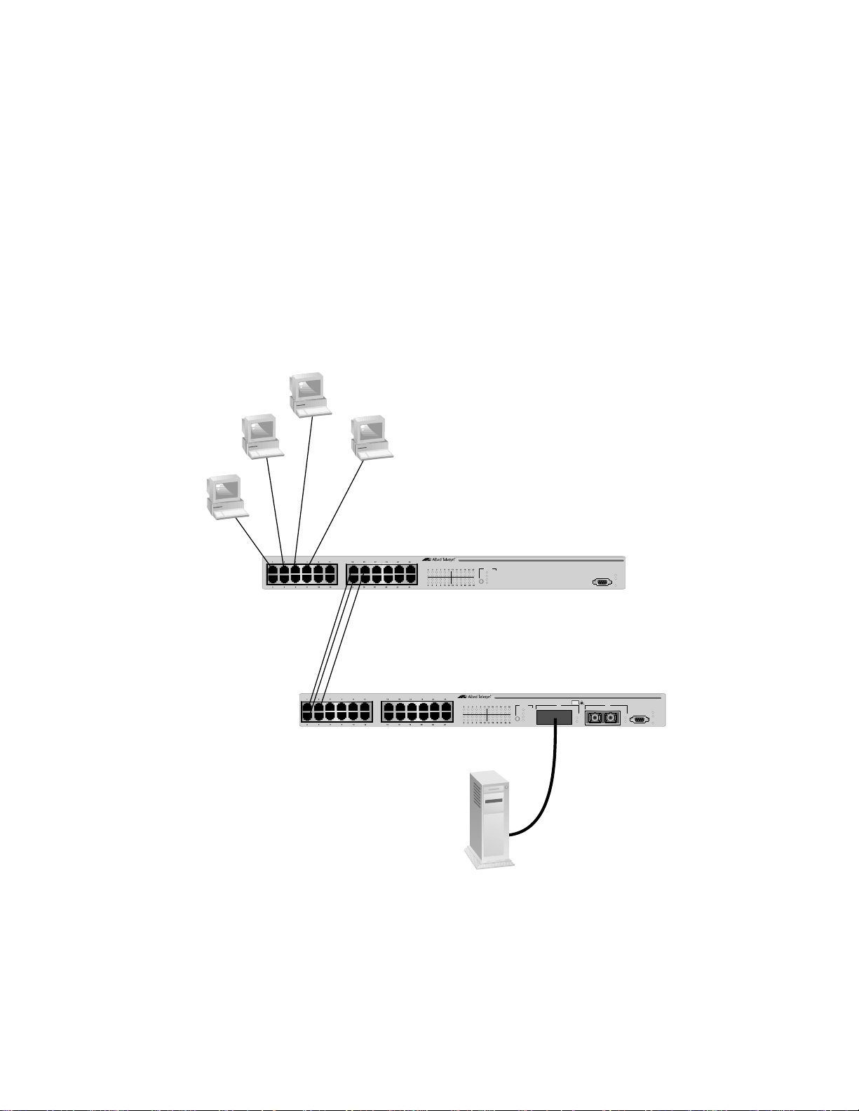
AT-S39 User’s Guide
The switch assigns source addresses so as to evenly distribute the
addresses, or at least as much as possible, across all the ports of the
trunk. The intent is to try and ensure that all links in the trunk are utilized.
Here is an example. Figure 20 shows two AT-8000 Series Switches, an AT8024 (Switch #1) and an AT-8024GB (Switch #2) interconnected with a
port trunk of three data links. The trunk on Switch #1 consists of Ports 13
to 15 and on Switch #2 of Ports 1 to 3. The 10Base and 100Base
workstations are directing traffic to a server connected to Switch #2. The
server is connected to Switch #2 with a fiber optic Gigabit Ethernet data
link provided by a 1000Base fiber optic GBIC module in the AT-8024GB
switch.
Workstation
C
Workstation
Workstation
A
Workstation
B
D
AT-8024
10Base-T/100Base-TX Fast Ethernet Switch
Link
Mode
Link
Mode
AT-8026FC
10Base-T/100Base-TX Fast Ethernet Switch
Link
Mode
Link
Mode
MODE
COL
100
FULL
ACT
MODE
COL
100
FULL
ACT
TX TXRX RX
RS-232 TERMINAL PORT
CLASS 1
LASER PRODUCT
DO NOT STARE
INTO BEAM
25
26
LINK
MODE
FAULT
MASTER
PWR
RS-232 TERMINAL PORT
LINK
MODE
Switch #1
FAULT
MASTER
PWR
Switch #2
Figure 20 Load Distribution Method
85
Page 86

Now assume that you configured the port trunk on Switch #1 for SA load
distribution. The switch might distribute the load as follow:
Table 1 Switch #1 Load Distribution
Source Workstation
Source MAC
Address
Trunk Port
A 00A0EE 2313A3 13
B 00A134 1A9032 14
C 00A301 9083B2 15
D 001B21 87C6D6 14
For example, when Workstation B sends a packet to the server, Switch #1
will use Port 14 of the trunk to transmit it to Switch #2.
An assignment of a source MAC address to a port trunk remains active as
long as the source node remains active. If the MAC address times out,
the assignment is dropped. Should the source node become active
again and need to transmit a packet over the trunk, a new assignment is
made, either to the same port or to a different port in the trunk.
It should be noted that packets sent back from the destination node to
the original source node may travel the same or a different data link in
the trunk.
As a general rule, the SA load distribution method is useful in situations
where the number of source nodes equals or is greater than the number
of data links in the trunk.
So when would the SA method be inappropriate? Let’s look back again
at the example in Figure 20. Let’s assume that you configured Switch #2
also for SA load distribution. The result would be that the switch would
use only one data link in the trunk to send packets back to Switch #1,
because there is only one source, a Gigabit Ethernet server, connected to
Switch #2. Since there is only one source, only one data link is used. So
obviously the SA method is not appropriate when there are fewer source
nodes than data links.
86
Page 87

AT-S39 User’s Guide
So now let’s look at the SA/DA method. A switch using the SA/DA
method creates a matrix of the source and destination MAC addresses
and then uses the matrix to determine which port in the trunk a frame is
to be transmitted. With this method, packets from a particular source
node might be sent over different data links in a trunk when sent to
different destination address e s.
So let’s take a look at how this might look in practice. Assume that you
configured Switch #2 in our example for SA/DA. The result might be
something similar to that shown in Table 2.
Table 2 Trunk Port Assignments in an SA/DA Matrix
Destinations MAC Addresses
Source MAC Address
Server
00B012 DA0231
Workstation
A
00A0EE 2313A3
Workstation
B
00A134 1A9032
Workstation
C
00A301 9083B2
Workstation
D
001B21 87C6D6
2131
Even though there is only one source, all the data links in the trunk are
used. For instance, if the server needed to send a packet to Workstation
C, by referring to the matrix Switch #2 would use Port 3 of the trunk to
transmit the packet from that particular source MAC address to Switch
#1.
As you can see, the SA/DA method is useful when a port trunk needs to
send packets from one source node to many destination nodes,
something that the SA method is not suited for. Additionally, the SA/DA
method is also valid when sending from many source nodes to one
destination node, or from many sources to many destinations.
The table below shows a possible matrix for a port trunk of three data
links using the SA/DA method, handling traffic from four sources to four
destinations.
87
Page 88

Table 3 Trunk Port Assignments in an SA/DA Matrix
Destinations Addresses
Source Addresses 00A0EE 2313A3 00A134 1A9032 00A301 9083B2 001B21 87C6D6
00B012 DA0231 1 2 3 1
001230 DA2943 2 3 1 2
0042AA D45A21 3 1 2 3
00456A C23521 1 2 3 1
The bottom line is that the SA/DA method is more flexible than the SA
method. A general rule to follow is if you are not sure which load
distribution to choose, you should probably go with SA/DA.
88
Page 89

Creating a Port Trunk
This section contains the procedure for creating a port trunk on the
switch. Be sure to review the guidelines in Port Trunking Overview on
page 83 before performing the procedure.
Caution
Do not connect the cables to the trunk ports on the switches until
after you have configured the trunk with the management
software. Connecting the cables before configuring the software
will create a loop in your network topology. Data loops c an result in
broadcast storms and poor network performance.
Note
Before creating a port trunk, examine the parameter settings of the
ports that will make up the trunk. Check to be sure that the settings,
such as speed and duplex mode, are the same for all the ports of the
trunk. You should also check to be sure that the ports are members
of the same VLAN.
AT-S39 User’s Guide
To create a port trunk, perform the following procedure:
1. From the Main Menu, type 1 to select Port Menu.
2. From the Port Menu, type 3 to select Port Trunking.
The Port Trunking menu in Figure 21 is displayed.
Allied Telesyn Ethernet Switch AT-8024
Login Privilege: Manager
Port Trunking
1 - Trunk Ports ..... None
S - Save Configuration Changes
R - Return to Previous Menu
Enter your selection?
Figure 21 Port Trunking Menu
89
Page 90

3. Type 1 to select Trunk Ports.
The following prompt is displayed.
Enter Trunk Port(s) ->
4. Enter the ports that will constitute the port trunk and press Return.
You can specify the ports individually (e.g., 1,2,3,4) or as a range
(e.g., 7-10).
Once you have specified the ports of the trunk, the following
menu selection appears:
2 - Trunk Method ....... SA/DA trunking
You can use this selection to specify the load distribution method.
The default is SA/DA.
5. To change the load distribution method, type 2 to toggle the
selection through its possible settings of SA/DA and SA only trunking.
The change in Port Trunking configuration is immediately activated
on the switch.
6. Type S to select Save Configuration Changes.
7. Configure the ports on the remote switch for port trunking.
8. Connect the cables to the ports of the trunk on the switch.
The port trunk is ready for network operation.
90
Page 91

Deleting a Port Trunk
Caution
Disconnect the cables from the port trunk on the switch before
performing the following procedure. Deleting a port trunk without
first disconnecting the cables can create loops in your network
topology. Data loops can result in broadcast storms and poor
network performance.
To delete a port trunk from the switch, perform the following procedure:
1. From the Main Menu, type 1 to select Port Menu.
2. From the Port Menu, type 3 to select Port Trunking.
The Port Trunking menu in Figure 21 on page 89 is displayed.
3. Type D to select Delete trunk.
A confirmation prompt is displayed.
AT-S39 User’s Guide
4. Type Y for yes to delete the port trunk or N for no to cancel this
procedure.
The deletion of the port trunk is immediately activated on the switch.
5. Type S to select Save Configuration Changes.
91
Page 92

Chapter 8
Port Mirroring
This chapter contains the procedures for creating and deleting a port
mirror. Sections in the chapter include:
❑ Port Mirroring Overview on page 93
❑ Creating a Port Mirror on page 94
❑ Deleting a Port Mirror on page 95
92
Page 93

Port Mirroring Overview
The port mirroring feature allows you to unobtrusively monitor the
traffic being received and transmitted on one or more ports on a switch
by having the traffic copied to another switch port. You can connect a
network analyzer to the port where the traffic is being copied and
monitor the traffic on the other ports without impacting network
performance or speed.
Observe the following guidelines when creating a port mirror:
❑ You can mirror from one to 23 ports on a switch at a time.
However, the more ports you mirror, the less likely the mirroring
port will be able to handle all the traffic. For example, if you mirror
the traffic of six heavily active ports, the mirror port is likely to
drop packets, meaning that it will not provide an accurate mirror
of the traffic of the other six ports.
❑ The ports to be mirrored and the mirroring port must be located
on the same switch.
AT-S39 User’s Guide
❑ The ports to be mirrored and the mirroring port must be
operating at the same speed. For example, you cannot use a
10/100 Mbps port to mirror traffic on a 1000 Mbps GBIC port.
93
Page 94

Creating a Port Mirror
To create a port mirror, perform the following procedure:
1. From the Main Menu, type 1 to select Port Menu.
2. From the Port Menu, type 2 to select Port Mirroring.
The Port Mirroring menu in Figure 22 is displayed.
Login Privilege: Manager
1 - Mirror (Destination) Port ....... None
2 - Mirroring (Source) Port(s) ...... None
S - Save Configuration Changes
R - Return to Previous Menu
Enter your selection?
Allied Telesyn Ethernet Switch AT-8024
Port Mirroring
Figure 22 Port Trunking Menu
3. Type 1 to select Mirror (Destination) Port.
The following prompt is displayed.
Enter Mirror port (0=None) [0 to 24] ->
4. Enter the number of the port to function as the mirror port (that is, the
port to where the traffic will be copied). Press Return.
You can specify only one mirror port.
5. Type 2 to select Mirroring (Source) Port.
The following prompt is displayed.
Enter Mirroring Ports (0=None):
6. Enter the number of the port whose traffic is to be mirrored. To mirror
the traffic of more than one port, enter the ports individually (e.g.,
1,4,6) or as a range (e.g., 11-14). Press Return.
7. Type S to select Save Configuration Changes.
The port mirror is now functional.
94
Page 95

Deleting a Port Mirror
To delete a port mirror, perform the following procedure:
1. From the Main Menu, type 1 to select Port Menu.
2. From the Port Menu, type 2 to select Port Mirroring.
The Port Mirroring menu in Figure 22 on page 94 is displayed.
3. Type 1 to select Mirror (Destination) Port.
The following prompt is displayed.
Enter mirror port (0=None) [0 to 24] ->
4. Enter 0 and press Return.
5. Type S to select Save Configuration Changes.
The port mirror on the switch is deleted. The port that was
functioning as the port mirror is now available for normal network
operations.
AT-S39 User’s Guide
95
Page 96

Chapter 9
STP and RSTP
This chapter provides background information on the Spanning Tree
Protocol (STP) and Rapid Spanning Tree Protocol (RSTP). The chapter
also contains procedures on how to adjust the STP and RSTP bridge and
port parameters. The sections in this chapter include:
❑ STP and RSTP Overview on page 97
❑ Enabling or Disabling STP or RSTP on page 105
❑ Configuring STP on page 106
❑ Configuring RSTP on page 110
Note
For detailed information on the Spanning Tree Protocol, refer to IEEE
Std 802.1d. For detailed information on the Rapid Spanning Tree
Protocol, refer to IEEE Std 802.1w.
96
Page 97

STP and RSTP Overview
A significant danger to Ethernet network performance is the existence of
a data loop in a network topology. A data loop exists when two or more
nodes on a network can transmit data to each other over more than one
data link. The problem that data loops pose is that data packets can
become caught in repeating cycles, referred to as broadcast storms, that
needlessly consume network bandwidth and significantly reduce
network performance.
STP and RSTP prevent data loops from forming by ensuring that only
one path exists between the end nodes in your network. Where multiple
paths exist, these protocols place the extra paths in a standby or
blocking mode, leaving only one main active path.
STP and RSTP can also activate a redundant path if the main path goes
down. So not only do these protocols guard against multiple links
between segments and the risk of broadcast storms, but they can also
maintain network connectivity by activating a backup redundant path in
case a main link fails.
AT-S39 User’s Guide
Where the two protocols differ is in the time each takes to complete the
process commonly referred to as convergence. When a change is made
to the network topology, such as the addition of a new bridge, a
spanning tree protocol must determine whether there are redundant
paths that must be blocked to prevent data loops, or activated to
maintain intercommunications between the various network segments.
This process is referred to as convergence.
With STP, convergence can take minutes to complete in a large network.
This can result in lost data packets and the loss of intercommunication
between various parts of the network during the convergence process.
RSTP is much faster. Rather than taking minutes, RSTP can complete a
convergence in seconds, and so greatly diminish the possible impact the
process can have on your network.
Note
RSTP is activated by default on the switch.
The STP implementation on the AT-8000 Series Switch complies with the
IEEE 802.1d standard. The RSTP implementation complies with the IEEE
802.1w standard. The following subsections provide a basic overview on
how STP and RSTP operate and define the different parameters that you
can adjust.
97
Page 98

Section II: Local and Telne t Management
Bridge Priority
and the Root
Bridge
The first task that bridges perform when a spanning tree protocol is
activated on a network is the selection of a root bridge. A root bridge
distributes network topology information to the other network bridges
and is used by the other bridges to determine if there are redundant
paths in the network.
A root bridge is selected by a combination of a bridge priority number,
also referred to as the bridge identifier, and sometimes the bridge’s MAC
address. The bridge with the lowest bridge priority number in the
network is selected as the root bridge. If two or more bridges have the
same bridge priority number, of those bridges the one with the lowest
MAC address is designated as the root bridge.
The bridge priority number can be changed on an AT-8000 Series switch.
You can designate which switch on your network you want as the root
bridge by giving it the lowest bridge priority number. You might also
consider which bridge should function as the backup root bridge in the
event you need to take the primary root bridge off-line, and assign that
bridge the second lowest bridge identifier number.
With STP, the bridge priority has a range of from 0 to 65535. You can
select any value within that range.
With RSTP, the range is slightly less, from 0 to 61440. Furthermore, you
can only select a value that is a multiple of 4096. To make this easier for
you, the management software divides the range into increments. You
specify the increment that represents the desired bridge priority value.
The range is divided into sixteen increments, as shown in the following
table.
Table 4 RSTP Bridge Priority Value Increments
Increment
Bridge
Priority
Increment
Bridge
Priority
0 0 8 32768
1 4096 9 36864
2 8192 10 40960
3 12288 11 45056
4 16384 12 49152
5 20480 13 53248
6 24576 14 57344
7 28672 15 61440
98
Page 99

AT-S39 User’s Guide
Path Costs and Port Costs
Once the Root Bridge has been selected, the bridges must determine if
the network contains redundant paths and, if one is found, they must
select a preferred path while placing the redundant paths in a backup or
blocking state.
Where there is only one path between a bridge and the root bridge, the
bridge is referred to as the designated bridge and the port through which
the bridge is communicating with the root bridge is referred to as the
root port.
If redundant paths exist, the bridges that are a part of the paths must
determine which path will be the primary, active path, and which path(s)
will be placed in the standby, blocking mode. This is accomplished by an
determination of path costs. T he path offering the lowest cost to the ro ot
bridge becomes the primary path and all other redundant paths are
placed into blocking state.
Path cost is determined through an evaluation of port costs. Every port
on a bridge participating in STP has a cost associated with it. The cost of
a port on a bridge is typically based on port speed. The faster the port,
the lower the port cost. The exception to this is the ports on the root
bridge, where all ports have a port cost of 0.
Path cost is simply the cumulation of the port costs between a bridge
and the root bridge.
The port costs of the ports on an AT-8000 Series switch are adjustable
through the management software, but the range is different
depending on whether you are using STP or RSTP.
For STP, the range is 1 to 65535. You can assign a port a port cost of any
value within the range. Below are the default values.
Table 5 STP Default Port Costs
Port Speed Port Cost
10 Mbps 10
100 Mbps 10
1000 Mbps 4
In RSTP, the range is much greater: 0 to 20 000 000. This greater range
allows you to have more control over path costs.
99
Page 100

Section II: Local and Telne t Management
RSTP port cost also features an Auto-Detect feature. This features allows
RSTP to automatically set the port cost according to the speed of the
port, assigning a lower value for higher speeds. Auto-Detect is the
default setting on the ports when the switch is operating in RSTP. Table
6 lists the ports cost with Auto-Detect.
Table 6 RSTP Auto-Detect Port Costs
Port Speed Port Cost
10 Mbps 2 000 000
100 Mbps 200 000
1000 Mbps 20 000
You can override Auto-Detect and set the port cost manually.
Port Priority
If two paths have the same port cost, the bridges must select a preferred
path. In some instances this can involve the use of the port priority
parameter. This parameter can be used as a tie-breaker when two paths
have the same cost.
In STP, the range for port priority is 0 to 255.
In RSTP, the range is 0 to 240. As with RSTP Bridge Priority, this range is
broken into increments, in this case multiples of 16. When you specify a
port priority for a port, you enter the increment of the desired value.
Table 7 RSTP Port Priority Value Increments
Increment
Bridge
Priority
Increment
Bridge
Priority
008128
1 16 9 144
2 3210160
3 4811176
4 6412192
5 8013208
6 9614224
7 112 15 240
100
 Loading...