

Page 1

◆
User’s Guide
Management
®
Software
AT-S21
For use with AT-8118, AT-8118XL, AT-8124XL and
AT-8126XL products
PN 613-10727-00 Rev. C
Page 2

Copyright 1998-1999 Allied Telesyn International, Corp.
960 Stewart Drive Suite B, Sunnyvale, CA 94086 USA
All rights reserved. No part of this publication may be reproduced w ithout prior written permission from Allied Telesyn International,
Corp.
CentreCom is a registered trademark of Allied Telesyn International, Corp.
Netscape Navigator is a registered trademark of Netscape Communications Corporation. All other product names, company names,
logos or other designations mentioned herein are trademarks or registered trademarks of their respective owners.
Allied Telesyn International, Corp. reserves the right to make changes in specifications and other information contained in this
document without prior written notice. The information provided herein is subject to change without notice. In no event shall Allied
Telesyn International, Corp. be liable for any incidental, special, indirect, or consequential damages whatsoever, including but not
limited to lost profits, arising out of or related to th is manual or the information contained herein, even if Allied Telesyn International,
Corp. has been advised of, known, or should have known, the poss ibility of such damages.
Page 3

7DEOH#RI#&RQWHQWV
Preface
Purpose of This Guide .....................................................................................................................................................................................................................v
How This Guide is Organized ....................................................................................................................................................................................................... v
Document Conventions .............................................. ........................ ........................ .................................................................................................................vi
Where to Find Related Guides ......................................................................................................................................................................................................x
..............................................................................................................................................................................................................................................v
Web Browser Interface........................................................................................................................................................................................................ vi
DEC VT100 Terminal Configuration............................................................................................................................................................................... vii
Generic (Dumb) Terminal Configuration.................................................................................................................................................................... viii
Enabling an Omega Option............................................................................................................................................................................................. viii
Menus........................................................................................................................................................................................................................................ ix
User-Supplied Variables...................................................................................................................................................................................................... ix
Chapter 1
Introduction
Software Features ................................................................................ ........................ ................................................................................................................1-2
Local Management .................................................................................... ........................ ..........................................................................................................1-3
Remote Management in Non-TCP/IP Networks ............................................................................................................................................................... 1-3
Remote Management In TCP/IP Networks .........................................................................................................................................................................1-4
TCP/IP With BootP or DHCP............................................................................................................................................................................................ 1-4
Management Through a Web Browser ........................................................ ........................ ................................................................................................1-5
Where to Go Next .........................................................................................................................................................................................................................1-5
...............................................................................................................................................................................................................................1-1
Chapter 2
Getting Started
Connecting a Terminal and Starting a Local Session ......................................................................................................................................................2-2
Switch Default Settings ................................ ........................ ........................ ..............................................................................................................................2-3
Setting Switch Defaults.................................................................................................................................................................................................... 2-3
Menu Navigation Using the Terminal Interface ................................................................................................................................................................2-5
Displaying Submenus....................................................................................................................................................................................................... 2-5
Enabling or Disabling an Option................................................................................................................................................................................... 2-5
Entering or Modifying Information.............................................................................................................................................................................. 2-6
Quitting the Terminal Interface..................................................................................................................................................................................... 2-6
Configuring IP Parameters ........................................................................................................................................................................................................2-7
Menu Navigation Using A Web Browser ..............................................................................................................................................................................2-8
Displaying Submenus..................................................................................................................................................................................................... 2-11
Selecting an Option............................................................................ ........................ ..................................................................................................... 2-11
Entering or Modifying Information............................................................................................................................................................................ 2-11
Quitting Omeg a ........................................................... ........................ ........................ ..................................................................................................... 2-11
Resetting the Switch .................................................................................................................................................................................................................2-12
About Optiona l Configurations ............................................................................................................................................................................................2-13
Menu Tree .....................................................................................................................................................................................................................................2-14
Where to Go Next .......................................................................................................................................................................................................................2-15
.........................................................................................................................................................................................................................2-1
iii
Page 4

7DEOH#RI#&RQWHQWV
Chapter 3
Configuration
IP Parameters ................................................................................................................................................................................................................................. 3-2
Port Configuration ....................................................................................................................................................................................................................... 3-4
Description of Options..................................................................................................................................................................................................... 3-5
Port Naming......................................................................................................................................................................................................................... 3-6
Fixed Port Names ............. ........................ ............ ........................ ........................ .............................................................................................................. 3-6
Spanning Tree Con figuration .................... .. .. .. .. .. .................. .. .. .. .. .. .. .. .. .. .. .. .................. .. .. .. .. .. .... .. .. ... .. .. .. ................ .. .. .. .. .. .. .. .. .. .. .. .................. .. .. .. .. .. .. .. .. .. .. .. .3-7
Configuring Spanning Tree Parameters..................................................................................................................................................................... 3-8
Configuring the Root Port............................................................................................................................................................................................... 3-9
System Configuration ............................................................ ........................ ...........................................................................................................................3-10
Naming the Switch.......................................................................................................................................................................................................... 3-11
Changing the Aging Time............................................................................................................................................................................................. 3-11
Configuring Omega......................................................................................................................................................................................................... 3-12
Configuring a Password................................................................................................................................................................................................. 3-13
Configuring a Timeout Value......................................................... ........................ ...................................................................................................... 3-13
Backpressure...................................................................................................................................................................................................................... 3-14
Terminal Configuration ............................................................................................................................................................................................................3-15
VT100 Compatible or ANSI.... ........................ ............ ........................ ........................ .................................................................................................... 3-15
Generic (Dumb) Terminal.............................................................................................................................................................................................. 3-15
Terminal Settings ............................................................................................................................................................................................................. 3-16
Virtual LAN Configuration .......................................................................................................................................................................................................3-17
Defining the VLANs ......................................................................................................................................................................................................... 3-19
Adding Ports to the VLAN............................................................................................................................................................................................. 3-21
Where to Go Next .......................................................................................................................................................................................................................3-22
............................................................................................................................................................................................................................3-1
Chapter 4
Monitoring and Administration
Activity Monitor ............................................................................................................................................................................................................................4-2
Connection to a Re mote Switch ............................................................................................................................................................................................. 4-3
Connectivity Verification (Ping) ..............................................................................................................................................................................................4-4
Ethernet Statistics ........................................................................................................................................................................................................................4-5
Navigating the Statistics Graphs Menus.................................................................................................................................................................... 4-5
Received Statistics........................ ............ ........................ ........................ .......................................................................................................................... 4-6
Transmit Fram es.................................. .. .. .. .. .. .. .. .. .. .. .. .................. .. .. .. .. .. .. .. .. .. .. .. ................................................................................................................. 4-8
Interpreting the Graphs................................................................................................................................................................................................. 4-10
MAC Address Table ...................................................................................................................................................................................................................4-11
Multicast Address............................................................................................................................................................................................................. 4-13
Static MAC Addr esses..................................................................................................................................................................................................... 4-15
Switch’s MAC A ddress Location.................................................................................................................................................................................. 4-16
Software Downloads ................................................................................................................................................................................................................4-17
Conditions for Network Downloads.......................................................................................................................................................................... 4-17
Using TFTP.......................................................................................................................................................................................................................... 4-17
Downloading Software to One Switch..................................................................................................................................................................... 4-18
Downloading Software to All Switches.................................................................................................................................................................... 4-19
Using XModem to Download Software................................................................................................................................................................... 4-20
....................................................................................................................................................................................... 4-1
Chapter 5
Diagnostics
Running Diagnostics ............................................................ ........................ ...............................................................................................................................5-2
Resetting Statistics Counters ...................................................................................... .............................................................................................................5-3
Resetting the Switch ...................................................................................................................................................................................................................5-4
Getting Help ...................................................................................................................................................................................................................................5-5
.................................................................................................................................................................................................................................5-1
Appendix A
Spanning Tree Concepts
Spanning Tree Protocol Features .......................... ........................ ........................ .................................................................................................................A-2
Spanning Tree Protocol Parameters ................................ ............ ........................ ........................ .........................................................................................A-3
Spanning Tree Oper a tio n .......... .. .. .. .. .. .................. .. .. .. .. .. .. .. .. .. .. .................. .. .. .. .. .. .. .. .. .. .. .. ..................... .. .. .. .. . . .. .. .................. .. .. .. .. .. .. .. .. .. .. .. .................. .. .. .. .. .. .A-4
Index
........... .. .. .. .. .. .. ... .. .................. .. .. .. .. .. .. .. .. .. .. .................. .. .. .. .. .. .. .. .. .. .. .. .................. .. ...... .. .. .. .. ................... .. .. .. .. .. .. .. .. .. .. .. .................. .. .. .. .. .. .. .. .. .. .. .. .........Index-1
iv
......................................................................................................................................................................................................A-1
Page 5

3UHIDFH
This guide documents the procedures to use Omega, the
management software (model AT-S21) that is pre-installed in
AT-8118, AT-8118XL, AT-8124XL, and AT-8126XL Fast Ethernet
switches from Allied Telesyn.
3XUSRVH#RI#7KLV#*XLGH
This guide is written for network admin istrators who are responsible
for configuring the management software and managing the
switches. Network administrators should be familiar with Ethernet
switches, Ethernet and Fast Ethernet technology, bridging, and the
spanning tree protocol.
+RZ#7KLV#*XLGH#LV#2UJDQL]HG
This guide is composed of the following sections:
Chapter 1,
AT-S21 software.
Chapter 2,
the Omega menus and entering initial configurations.
Chapter 3,
switch settings to suit your network environment.
Chapter 4,
procedures for viewing status information and performing
administrative tasks on the switch.
Introduction
Getting Started
Configuration
Monitoring and Administration
, describes the features and functions of the
, describes the procedures for navigating
, describes the procedures for modifying
, describes the
v
Page 6

'RFXPHQW#&RQYHQWLRQV
Chapter 5,
implement in case the switch malfunctions.
Appendix A,
Spanning Tree Protocol (STP) as implemented by Allied Telesyn on
the switches.
Index
'RFXPHQW#&RQYHQWLRQV
The Omega menus are available from the following user interfaces:
:HE#%URZVHU
,QWHUIDFH
This guide is written entirely based on the switch’s web browser
interface. The web browser interface works in TCP/IP networks and
requires a web browser such as Netscape’s Navigator®. The switch
also requires a valid IP address. For details, refer to Chapter 2,
Getting Started
Diagnostics
Spanning Tree Concepts
, describes the testing procedures to
, briefly describes the
, at the end of this guide, is according to subject matter.
Graphical user interface via a web browser
❑
Text-based interface via a DEC VT100 terminal configuration
❑
Text-based interface via a generic terminal configuration
❑
.
vi
Page 7

$70654#8VHU·V#*XLGH
'(𗲙
7HU PLQ DO
&RQILJXUDWLRQ
If you are using the DEC VT100 or ANSI (the default) terminal
configuration:
When directed to You must
Select an option Highlight the option by pressing the Up (↑)
or Down (↓) arrow key; then press
<Return>
or
Type the
first character
of the option you
want at the prompt and then press
<Return>
.
If two or more options hav e mat ching initial
characters, type the initial character enough
times until the option you want is
Enter information, for
example,
IP address
highlighted; then press
<Return>
Type the correct IP address and press
<Return>
.
Return to the previous
screen
Select the option
or
Press
<Esc>
vii
Page 8

'RFXPHQW#&RQYHQWLRQV
*HQHULF#+'XPE,
7HU PLQ DO
&RQILJXUDWLRQ
If you are using the generic (dumb) terminal configuration:
When directed You must
To select an option Type the
want and then press
first character
of the option you
<Return>
If two or more options have matching initial
characters, type enough characters for
Omega to distinguish your choice from the
other options; then press
<Return>
guide you, the characters you must type are
in uppercase.
For example:
Mirroring configuration
MAC Address Table
If options on a list are preceded by numbers
(1:, 2:, 3:, etc.), type the number
corresponding to your choice at the
prompt; then press
<Return>
.
. To
.
(QDEOLQJ#DQ
2PHJD#2SWLRQ
To enter information,
for example,
IP
Type the correct IP address at the prompt
and press
<Return>
.
address
To return to the
Press
<Return>
after making an entry.
previous screen
In text-based interfaces, Omega denotes an enabled option by
preceding it with a >.
For example, the following screen shows a port that is enabled:
> Enable this port
Disable (partition) this port
If your terminal configuration is DEC VT100, enabled configurations
also appears darker.
viii
Page 9

$70654#8VHU·V#*XLGH
Warning
Caution
Enable this port
> Disable (partition) this port
If you enable another option, Omega moves the > to the new option.
For example:
0HQXV
8VHU06XSSOLHG
9DU L DEO H V
Menus and submenus are represented in courier type. In this guide,
menu hierarchies are separated by a >.
Menu: System configuration
Menu: System configuration>IP parameters
Variables are information you must supply, such as IP addresses, MAC
addresses, or port numbers. Variables are in Italics and enclosed in
angle brackets (<>).
For example, to configure a specific port:
Select Port status and configuration>
<
PortNumber
where <
PortNumber
>
> can be 1, 2, and so on.
Note icons
Note
Notes provide additional information.
Warning icons
Warnings inform you that performing or omitting a specific action
may result in bodily injury.
Caution icons
Cautions inform you that performing or omitting a specific action
may result in equipment damage or loss of data.
ix
Page 10

:KHUH#WR#)LQG#5HODWHG#*XLGHV
:KHUH#WR#)LQG#5HODWHG#*XLGHV
Allied Telesyn wants our customers to be well informed b y pr ov iding
the most up-to-date and most easily accessible way to find our
guides and other technical information.
Visit our website at:
www.alliedtelesyn.com
and download the
following guide:
AT-S21 Software Management User’s Guide
, 613-10727-00
AT-8118 AT-8118XL, AT-8124XL, and AT-8126XL
Installation Guide
, 613-10726-00
The following guides are shipped with their respective products:
AT-8118, AT-8118XL, AT-8124XL, and AT-8126XL Quick
613-10729-00
Install Guide
,
AT-8118, AT-8118XL, AT-8124XL, and AT-8 126XL
Translated Safety Information Booklet
AT-A10 and AT-A11 Quick Install Guide
, 613-10728-00
,
613-10742-00
x
Page 11

&KDSWHU#4
,QWURGXFWLRQ
This chapter describes:
The features of AT-S21 Management Software for the
❑
AT-8118, AT-8118XL, AT-8124XL, and AT-8126XL Fast Ethernet
switches
An overview of the networking environments for you to
❑
optimize AT-S21’s management features
Make sure the switch is installed in the network and operating
normally. Follow the procedures in the
AT-8124XL, and AT-8126XL Switches Quick Install Guide
shipped with the switch; or in the
and AT-8126XL Fast Ethernet Switches Installation Guide
you can download from Allied Telesyn’s website at
www .alliedtelesyn.com
.
AT-8118, AT-8118XL,
that is
AT-8118, AT-8118XL, AT-8124XL,
that
1-1
Page 12

6RIWZDUH#)HDWXUHV
6RIWZDUH#)HDWXUHV
The AT-S21 software provides the following management features:
Factory-installed and ready to use
❑
Support for management through a web browser
❑
User configuration for per-port packet switching: store-and-
❑
forward or, for 100 Mbps only, fragment-free cut-through
Auto-negotiation for full- or half-duplex and 10 Mbps or 100
❑
Mbps speed
Bridging support, including Spanning Tree Protocol (STP)
❑
System configuration, management, and diagnostics using
❑
Allied Telesyn’s interface,
Omega
, accessible locally via an
RS232 asynchronous terminal, remotely via Telnet, or a web
browser
Software upgrades using Xmodem via the RS232 port or TFTP
❑
to download software to other AT-8118, AT-8118XL,
AT-8124XL, and AT-8126XL switches on the network
Password override
❑
SNMP agent that allows switch management from the
❑
administrator’s network management station
Support for TCP/IP’s BootP parameters and Dynamic Host
❑
Configuration Protocol (DHCP)
Support for port-based Virtual LANs (VLANs)
❑
Support for DEC VT100/ANSI (the default), or generic (dumb)
❑
terminal configuration
Internet Control Message Protocol (ICMP) Echo (PING) support
❑
Domain name service support (DNS).
❑
1-2
Page 13
/RFDO#0DQDJHPHQW
$70654#8VHU·V#*XLGH
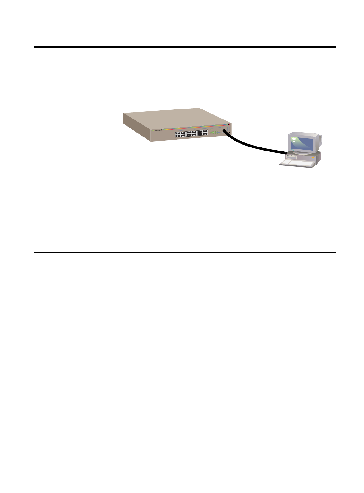
The switch’s software is factory-installed and ready to use. Y ou can
access the management menus (Omega Local) by directly
connecting a terminal or a PC to the switch’s RS232 port on the front
panel (Figure1-1) and using your terminal emulator program.
STATUS
RS-232
TERMINAL PORT
10BASE-T / 100BASE-TX
FAST ETHERNET SWITCH
10BASE-T / 100BASE-TX
PORT ACTIVITY
Figure 1-1
Switch With Terminal or PC
Setting up the terminal emulator program is described later in
Chapter 2, the section on
Local Session
on page 2-2.
Connecting a Terminal and Starting a
5HPRWH#0DQDJHPHQW#LQ#1RQ07&32,3#1HWZRUNV
In non-TCP/IP environments, you communicate with the switch from
a remote location (Omega Remote) by entering its pre-configured
MAC address, located below the RS232 port on the front panel
(Figure1-1).
At a later time, you can assign an easy-to-remember switch name
through the System Administration menus (described later in
Chapter 3 in the section,
System Configuration
on page 3-10).
1-3
Page 14

5HPRWH#0DQDJHPHQW#,Q#7&32,3#1HWZRUNV
5HPRWH#0DQDJHPHQW#,Q#7&32,3#1HWZRUNV
In a TCP/IP network, the switch requires a set of IP parameters, such
as a unique IP address and subnet mask, for communication. The
switch obtains its IP parameters in one of the following ways:
You assign the IP parameters through Omega’s System
❑
configuration>IP Parameters menu (described later
in Chapter 2, the section on
Terminal Interface
The switch obtains IP parameters from a BootP or DHCP server.
❑
At a later time, you can assign a switch name that’s easy to
❑
remember, using the System Administration menus
(described later in Chapter 3 in the section,
Configuration
on page 2-5).
on page3-10).
Menu Navigation Using the
System
7&32,3#:LWK
%RRW3#RU#'+&3
If you have BootP or DHCP, the switch can obtain its IP parameters
from the BootP or DHCP server during startups. In this case, you
simply connect the switch to the network.
The function of the BootP or DHCP utility within an IP server is to
provide IP parameters, including an IP address, to the switch.
Whenever you reset or power on and off the switch, the switch
transmits a request packet to the server every three seconds to
obtain the required IP parameters. The switch makes three request
attempts.
If the requesting switch does not receive a BootP or DHCP response
after the third request, it will operate with a computed pseudo IP
address based on the switch’s MAC address.
If the switch receives a response from the BootP or DHCP server, the
switch extracts the IP address, Subnet Mask, or Gateway/Router
address and uses these parameters to configure itself until the next
power-on or reset. Additionally, if the BootP response packet
specifies a filename and a TFTP host address, then the switch sends a
TFTP
request to the specified host using the specified filename.
get
This initiates a TFTP download of operating software and allows you
to maintain the downloaded software on your server.
1-4
Page 15

0DQDJHPHQW#7KURXJK#D#:HE#%URZVHU
Those familiar with web browsers such as Netscape Navigator® can
access Omega menus by entering the switch’s IP address (or a unique
name) in the URL field. With a web browser, you enjoy the following
advantages:
Use of your favorite browser’s point-and-click graphical
❑
interface and navigational tools to totally bypass Omega’s
hierarchical terminal interface
Bookmarking capabilities so you store switches’ IP addresses;
❑
or go directly to most frequently-used Omega menus instead
of navigating through a hierarchy of menus
Browser-based security to prevent unauthorized access
❑
$70654#8VHU·V#*XLGH
:KHUH#WR#*R#1H[W
Details are described in Chapter 2, the section on
Using A Web Browser
Proceed to Chapter 2,
Connecting a terminal for local management
❑
Entering IP parameters to manage the switch in a TCP/IP
❑
on page2-8.
Getting Started
, for information on:
network
Using a web browser to manage the switch
❑
Using the standard Omega terminal interface to manage the
❑
switch
Menu Navigation
1-5
Page 16

Page 17

&KDSWHU#5
*HWWLQJ#6WDUWHG
This chapter describes ways to start Omega after you have installed
the switch on the network.
This chapter includes the following information:
❑
Connecting a Terminal and Starting a Local Session
page2-2
❑
Switch Default Settings
❑
Menu Navigation Using the Term inal Interface
❑
Configuring IP Parameters
❑
Menu Navigation Using A Web Browser
❑
Resetting the Switch
❑
About Optional Configurations
❑
Menu Tree
on page2-14
on page2-3
on page2-7
on page2-8
on page 2-12
on page2-13
on
on page 2-5
2-1
Page 18

&RQQHFWLQJ#D#7HUPLQDO#DQG#6WDUWLQJ#D#/RFDO#6HVVLRQ
&RQQHFWLQJ#D#7HUPLQDO#DQG#6WDUWLQJ#D#/RFDO#6HVVLRQ
This procedure applies if:
You are managing the switch locally.
❑
You are managing the switch in a TCP/IP environment and you
❑
are configuring IP parameters for the first time.
1. Connect a terminal or PC directly to the switch’s RS232 port and
configure the terminal or emulation program as follows:
VT100 emulation
8 data bits
1 stop bit
No parity
9600 bps
2. Press
<Return>
.
The main Omega menu displays.
Allied Telesyn AT-8124XL Ethernet Switch: 1.0
Port status and configuration
Ethernet statistics
Administration
System configuration
Virtual LANs
Bridging
MAC Address Table
Quit
Main Menu
2-2
Figure 2-1
Main Menu
As a default, the software does not require a password for access. Y ou
may later configure a password (described in Chapter 3 in the
section,
System Configuration
on page 3-10). The switch is now
operational at the default settings listed in Table2-1.
Page 19

6ZLWFK#'HIDXOW#6HWWLQJV
Warning
$70654#8VHU·V#*XLGH
6HWWLQJ#6ZLWFK
'HIDXOWV
To set your switch to the factory defaults, do the following:
This operation deletes existing switch configurations.
1. Attach a terminal to the RS232 port located on the front panel of
the switch and begin the terminal emulation program.
2. Press
<Reset>
located on the right side of the switch’s front panel.
3. Immediately press any key when you see Hit any key to run
diagnostics or to reload system software
A menu
.
then displays.
4. Select D from the menu. The following warning message displays:
WARNING: This will erase all current
configuration data!
Continue? Y/N
5. Select Y. The system displays: All configuration data has
been reset to factory default values.
Press
to boot the switch software
<B>
2-3
Page 20

6ZLWFK#'HIDXOW#6HWWLQJV
Table 2-1
Default Settings
Settings Default
IP Address 0.0.0.0
Subnet Mask 0.0.0.0
Gateway Address 0.0.0.0
Get community string Public
Set community string Private
Trap community string Public
Forwarding Method Store-and-forward
Spanning T ree Protocol Disabled
Telnet Access Enabled
System Name None
Passwor d (Omega) No password assigned
Timeout value 5 minutes
Download Password ATS21
Transmission mode (per port) Auto-negotiating
MAC Address T able ’s Active Aging Time 300 seconds
High Port Speed Auto-negotiating
Domain Name None
VLAN name Default VLAN
2-4
Page 21

0HQX#1DYLJDWLRQ#8VLQJ#WKH#7HUPLQDO#,QWHUIDFH
As a default, Omega’s terminal interface is configured to use a DEC
VT100 or ANSI terminal, or an equivalent terminal emulator program.
$70654#8VHU·V#*XLGH
'LVSOD\LQJ
6XEPHQXV
(QDEOLQJ#RU
'LVDEOLQJ#DQ
2SWLRQ
At startup, Omega highlights the first item on the main menu
(Figure2-1 on page 2-2).
To select a menu option:
1. Press the up (↑), down (↓), left (←), or right (→) arrow key to
highlight an option.
2. Press
<Return>
.
Omega displays the enabled option in bold and precedes it with a
symbol. For example, to view information about a port:
1. Select Port status and configuration from the main menu to display a list of ports.
2. Select a port number, for example, Port 11, by pressing the up
arrow key to highlight it; and then press
<Return>
to display its
configuration information:
Port Configuration Menu
Port 11
Link State:Offline
Port State:Enabled
>
Enabled options
Please select an option:
> Enable this port
Disable (partition) this port
> Auto negotiate
Full duplex
Half duplex
> Store-and-forward
Cut-through (for 100MBPS operation)
Port name
Return to Port Status Menu ...
Figure 2-2
Sample Port Configuration Menu, Terminal Interface
2-5
Page 22

0HQX#1DYLJDWLRQ#8VLQJ#WKH#7HUPLQDO#,QWHUIDFH
(QWHULQJ#RU
0RGLI\LQJ
,QIRUPDWLRQ
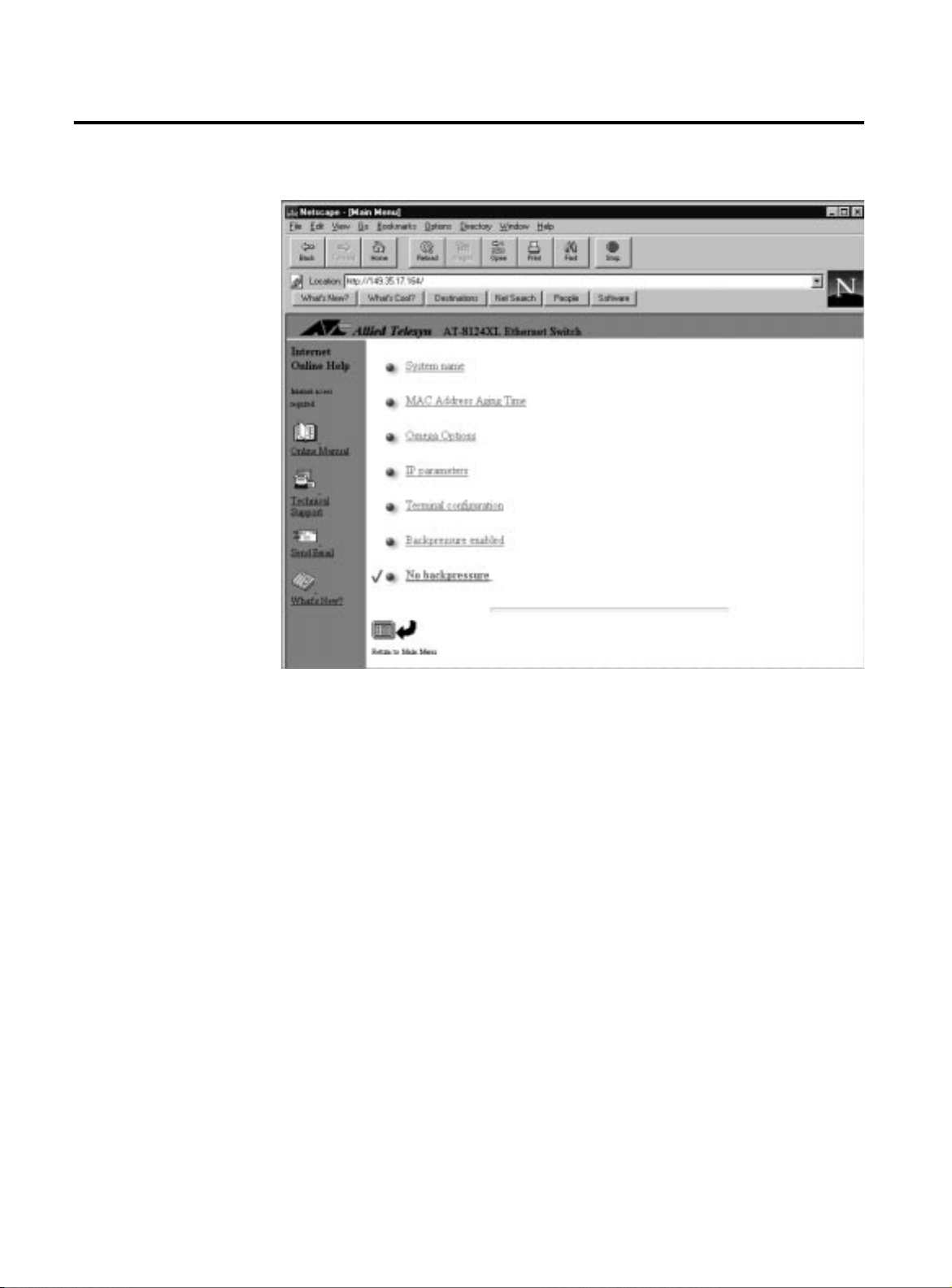
System name ->
MAC Address Aging Time 300
Omega Options
IP parameters
Terminal Configuration
Backpressure enabled
> No backpressure
Return to Main Menu ...
Omega precedes type-in fields with the -> symbol.
To configure the switch’s name:
1. Select System configuration>System name to display the System Configuration Menu.
The first option, System name, is highlighted.
2. Configure the switch name at the prompt as follows:
❑
Press
<Return>
at the highlighted area to insert a type-in field
and enter a text string.
Type-i n field
System Configuration Menu
4XLWWLQJ#WKH
7HU PLQ DO
,QWHUIDFH
To delete the existing information, enter one or more space
❑
characters and press <
If you press <
❑
Return>
Return>
before entering any characters, the
.
previous configuration value remains unchanged.
The new or changed switch name displays at the top of the
screen; a deleted name no longer appears.
To quit Omega, select
from the main menu.
Quit
If you do not quit Omega from a local session, future Telnet sessions
to the switch will be blocked.
If you are currently in a Telnet session, you must additionally
disconnect Telnet after quitting Omega. Otherwise, future Telnet
sessions to the switch will be blocked.
You may configure a timeout value so that the switch automatically
disconnects Telnet sessions after a period of inactivity. See Chapter 3,
section on
Configuring a Timeout Value
on page3-13, for the
procedures.
2-6
Page 23

&RQILJXULQJ#,3#3DUDPHWHUV
Skip this section if you have a non-TCP/IP network or if you have
TCP/IP but use a BootP or DHCP server to provide IP parameters.
$70654#8VHU·V#*XLGH
This procedure provides the
minimum
IP configurations you need to
enter so that the switch can be part of your TCP/IP network.
Assigning a unique IP address to the switch provides an advantage:
the switch uses the same IP parameters despite resets and power
cycles.
1. Select System configuration>IP Parameters from the
main menu.
2. Select IP address, press
<Return>
to insert a type-in field, and
enter a unique IP address for the switch.
3. Select Subnet mask and enter the switch’s subnet mask.
4. Select Gateway address and enter the address if you are
sending packets to another IP network.
The gateway address is the router that can forward packets to
the other IP networks.
Once the switch has an IP address, you may initiate Omega sessions
to it via Telnet or a web browser. Note that you can only have one
Telnet session operating at any one time. The session can be either
inbound or outbound. If y ou ha v e an inboun d session to Omega, yo u
do not have the option of starting a new session (outbound
connection). Therefore, if you are already using Telnet, the Omega
option Connect to a remote system will not be available
(described in detail in Chapter 4,
Monitoring and Administration
).
In addition, a local RS232 connection blocks a T elnet session and vice
versa.
For more on IP parameter configuration, go to Chapter 3 and refer to
the section,
IP Parameters
on page3-2.
Note
For non-IP environments, you can use MAC addresses to connect to
remote Allied Telesyn switches as long as there are no routers
between the two switches. If you have assigned unique names, you
may use these in place of MAC or IP addresses.
2-7
Page 24

0HQX#1DYLJDWLRQ#8VLQJ#$#:HE#%URZVHU
0HQX#1DYLJDWLRQ#8VLQJ#$#:HE#%URZVHU
This guide is primarily based on the web browser interface.
To use the web browser interface, make sure your switch has been
assigned a unique IP address or a switch name (see previous section).
This section shows you how to:
Configure your web browser to access the switch’s Omega
❑
menus.
Use the browser’s navigational tools in combination with
❑
Omega’s commands to configure the switch.
The examples are based on Netscape’s Navigator®; you can use other
popular browsers.
When directed by this guide to select something, that means you click on it.
Note
1.
If your PC with the browser is on the same side of a firewall as
the switch
, configure your browser’s network options not to use
any proxies; otherwise, skip to Step 2.
Consult your web browser’s docume ntation on how to
configure the switch’s IP address not to use proxies.
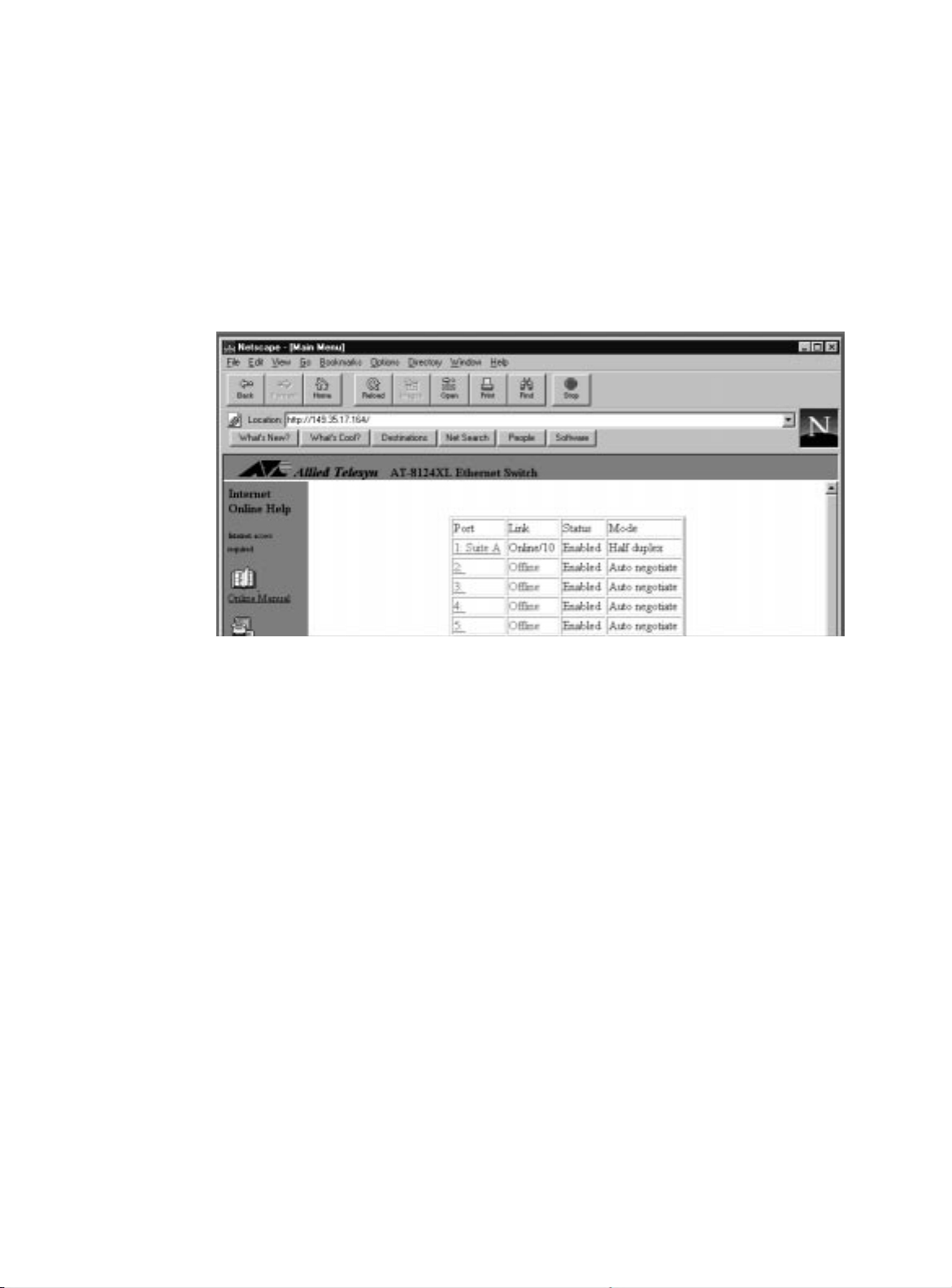
2. Enter the switch’s IP address (or name) in the locator field:
Switch’s IP address
Figure 2-3
Entering the Switch’s IP Address
2-8
Page 25

The switch view appears as shown in Figure 2-4:
$70654#8VHU·V#*XLGH
Links to Allied Telesyn’s web page (to the Internet)
Port area
Netscape Navigator’s toolbar
Main menu
Figure 2-4
The Switch View
3. Select, that is, click on, menu items as follows:
Select the front panel of the switch to select an option or
display information. Depending on the area you click, you
either start from a list of all ports or you select a specific port.
Select
on your browser’s toolbar to return to the
Back
previous display.
Select
Return to Main Menu
(not available at each display) at
the bottom of the Omega display to return to the main menu.
Use the browser’s
bookmark
feature on frequently-used
views to bypass any Omega menu hierarchies.
4. Link to other Allied Telesyn sites as follows:
Select
Online Manual
to go to Allied Telesyn’s technical
communications web page and download the switch’s related
guides in PDF.
Select
Technical Support
to go to Allied Telesyn’s Technical
Support web page and learn about other support services.
2-9
Page 26

0HQX#1DYLJDWLRQ#8VLQJ#$#:HE#%URZVHU
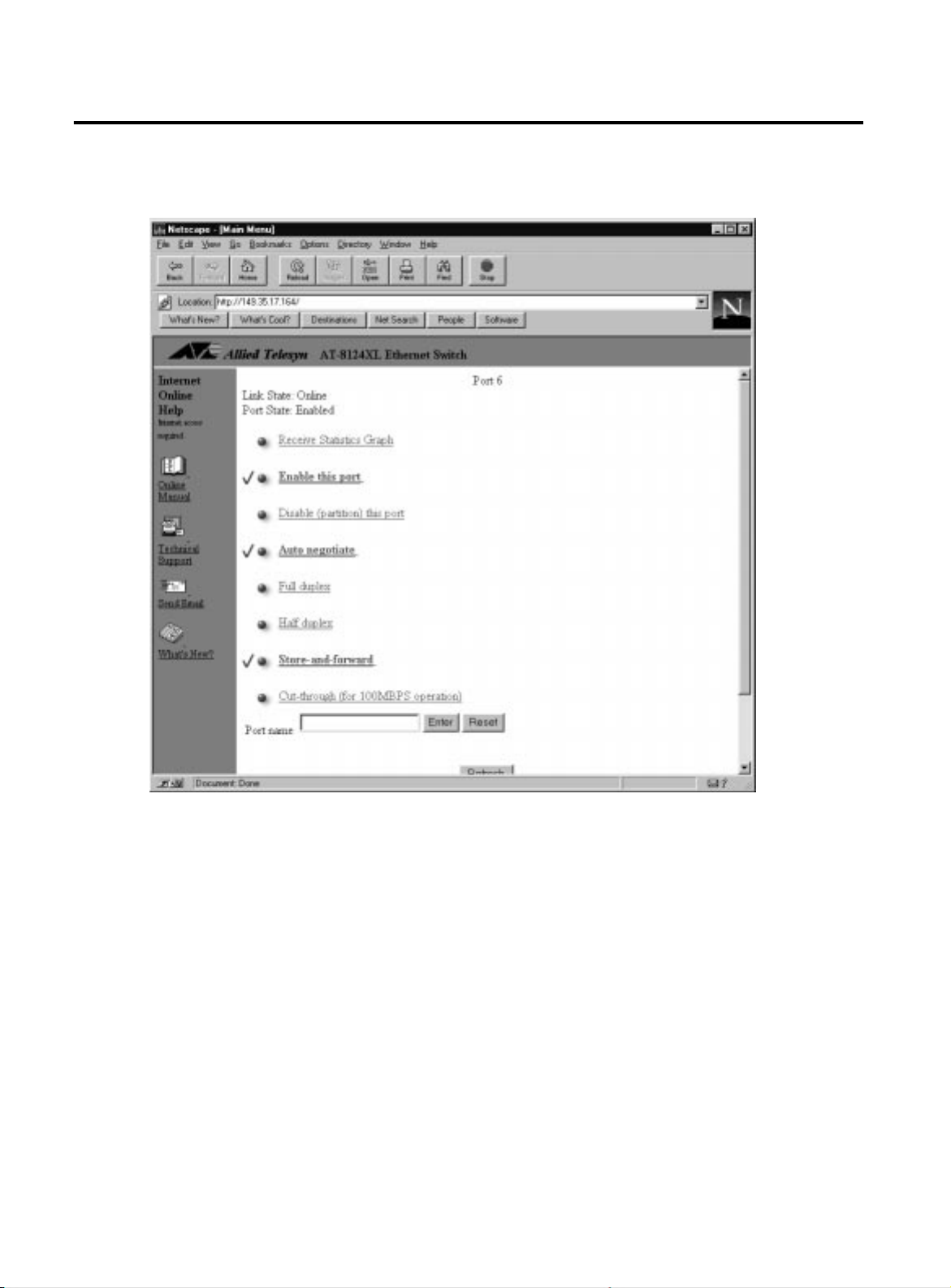
Click on Port 6 from the list of ports...
Select
Send Email
to submit feedback, questions, or any other
information to Allied Telesyn.
Select
What’s New?
to find out about Allied Telesyn’s latest
product offerings.
Figure2-5 shows additional examples on how the Omega menus
work.
... to display Port 6’s Configuration Menu
2-10
Figure 2-5
Sample Omega Menus
Page 27

$70654#8VHU·V#*XLGH
'LVSOD\LQJ
6XEPHQXV
6HOHFWLQJ#DQ
2SWLRQ
(QWHULQJ#RU
0RGLI\LQJ
,QIRUPDWLRQ
Underlined text on the display indicates it is a selectable item that,
when selected, displays another menu or execute a command. For
example, in Figure2-5, clicking on a specific port number (Port 6)
from the port list displays a menu specific to Port 6.
Menu hierarchies are represented as follows:
System configuration>System name
When directed to select the above command, first you select
System configuration from the main menu to display a
submenu; then select System name on the submenu.
Enabled options are underlined and darker than the other options.
For example, on Figure 2-5, Port 6 is set to
Auto-negotiate
change its transmission mode by clicking on either
Half-duplex
.
Full-duplex or
. You can
You enter a text string in a type-in field similar to Figure2-6.
4XLWWLQJ#2PHJD
Figure 2-6
To enter information, type the text string in the field and select
❑
.
Enter
To change existing information, select the displayed text
❑
string, type the new information to modify, and select
To delete information, select the displayed text string, press
❑
<Backspace>
To retain current configuration without accepting changes,
❑
select
To update the screen with recently-entered configurations,
❑
select
Reset
Refresh
, and then select
instead of
. (Not all screens have
Type-In Field
Enter
.
Enter
.
Refresh
Enter
.)
To disconnect from the switch through the browser, you must quit
your browser.
While you are in the browser and you link to other sites, you are still
logged in to Omega. You may return to the Omega web pages
anytime as long as you do not quit the browser.
.
2-11
Page 28

5HVHWWLQJ#WKH#6ZLWFK
5HVHWWLQJ#WKH#6ZLWFK
You may occasionally need to reset the switch. There are three ways
to do so:
Use the switch’s
❑
RESET
button on the front panel to perform a
hardware reset on the switch. Press this button with a pointed
object, such as a ballpoint pen.
Use Omega’s
❑
Reset and restart
option. This option enables
you to perform a software reset from a local terminal or from a
remote location via Telnet or the web browser.
Unplug the switch’s power cord from the power source, and
❑
plug it back in to recycle power and reset the switch.
2-12
Page 29

$ERXW#2SWLRQDO#&RQILJXUDWLRQV#
Other than assigning the switch’s IP address for a TCP/IP network,
you do not need to change the default settings in the management
software. On the other hand, network administrators may prefer to
use the configurable options for their individualized switch
performance. For example:
Name the switch and its ports
❑
An IP or MAC address is enough to communicate with the
switch on the network, however, names are descriptive and
easy to remember. You can configure a name to the switch or
its ports.
Port names can be associated with the user assigned to the
port or an office location. The need to use symbolic names
becomes more apparent as you add more switches and
therefore multiply the number of ports you must manage.
$70654#8VHU·V#*XLGH
Enable security features
❑
Although passwords are not required to access the
management menus, with the Omega Options menu, you can
prevent (disable) either Omega Local or Omega Remote,
create password protection, and enable timeout.
A timeout value automatically terminates a management
session after a given period when someone leaves a current
session unattended.
2-13
Page 30
0HQX#7UHH
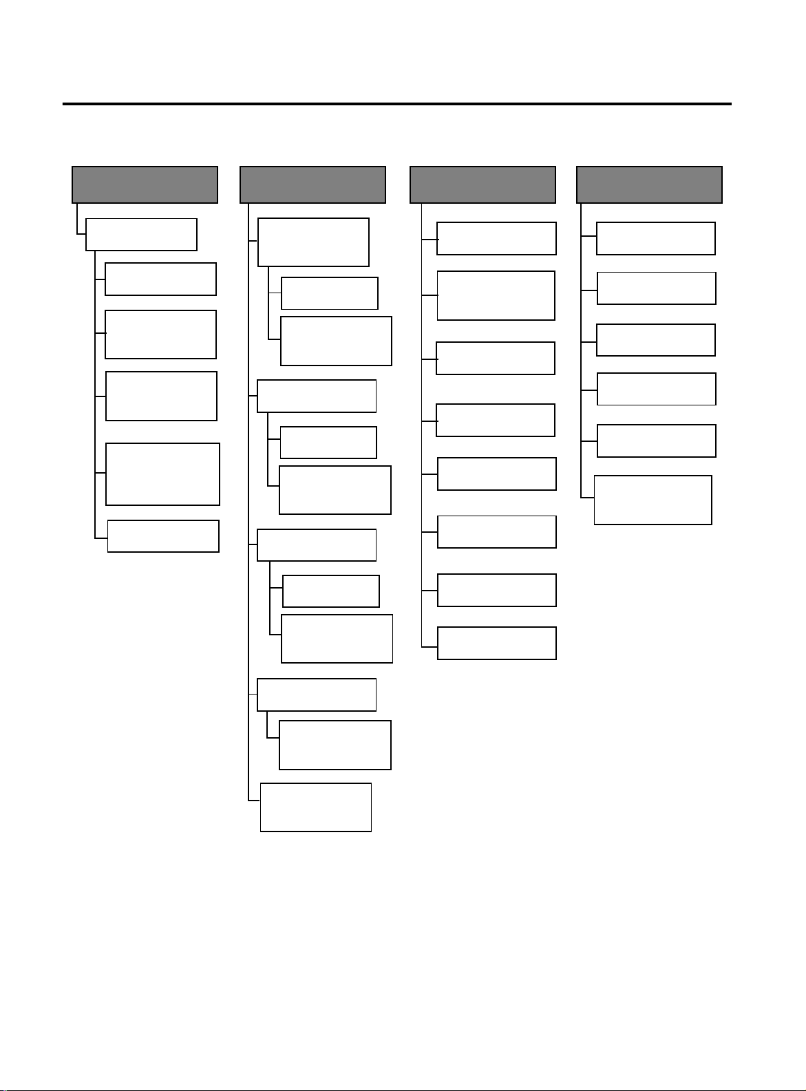
0HQX#7UHH
The following Omega menu tree is provided for your easy reference.
Port status and
configuration
Port number
Receive Statistics
Graph
Enable this port
Disable (partition)
this port
Auto negotiate
Full duplex
Half duplex
Store-and-forward
Cut-through
(100 Mbps
operations)
Port name
Ethernet Statistics
Receive Sta tistics
Graph
(all ports)
Individual port
overview . . .
Zero all st atistics
counters on the
entire system
Transmitted frames
statistics
Individual port
overview
Zero all statistics
counters on the
entire system
Individual Port
Overview . . .
Administration
Update Software in
another system
Broadcast updated
Software to
all systems
XModem
software update
Remote system
connection
Ping a remote
system
Activity monitor
System
Configuration
System name
MAC address
Aging T ime
Omega Options
IP parameters
Terminal
configuration
Backpressure
enabled
>
No backpressure
More . . .
Zero all statistics
counters on the
entire system
RMON Statistics . . .
Zero all statistics
counters on
entire system
Zero all statistics
counters on
entire system
Figure 2-7
Diagnostics
Reset and restart
the System
Omega Menu Tree, 1 of 2
2-14
Page 31
$70654#8VHU·V#*XLGH
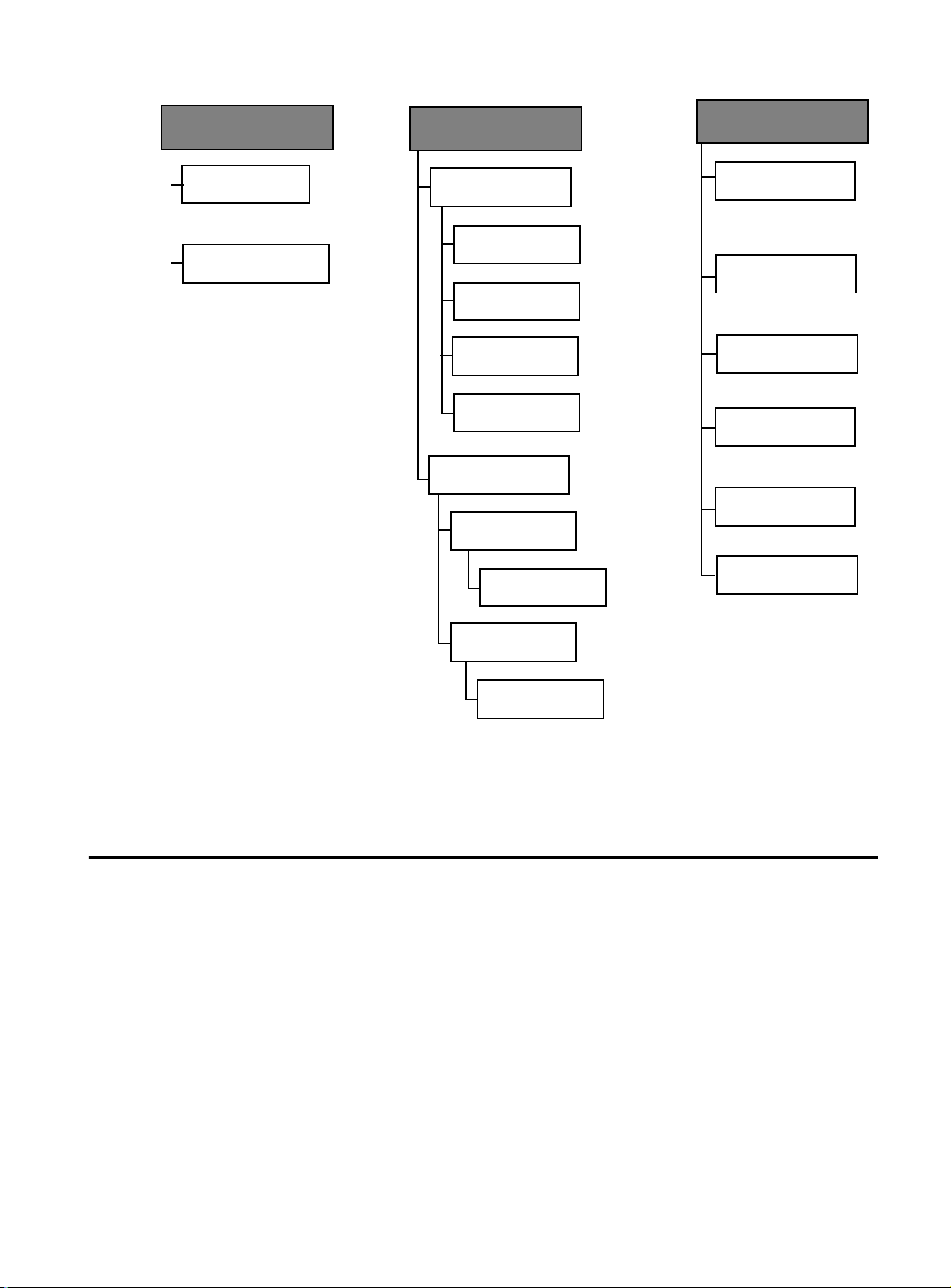
Virtual LANs
Virtual LAN
definitions
Port to VLAN
configuration
Bridging
Spanning tree
parameters
Bridge
Priority
Max Age
Time
Hello
Time
Forwarding
Delay
Port spanning
tree configuration
Enable spanning
tree for all ports
Enable spanning
tree by port
MAC Address
Table
Show all MAC
addresses
By port MAC
addresses
All static MAC
addresses
Per port static
MAC addresses
Multicast
addresses
Clear static MAC
table
:KHUH#WR#*R#1H[W
Disable spanning
tree for all ports
Disable spanning
tree by port
)LJXUH##50:#
2PHJD#0HQX#7UHH/#5#RI#5
Proceed to Chapter 3 to configure the switch; and to Chapter 4 to
monitor and administer the switch.
2-15
Page 32

Page 33

&KDSWHU#6
&RQILJXUDWLRQ
This chapter describes the following procedures to optimize your
switch configurations:
❑
IP Parameters
❑
Port Configuration
❑
Spanning Tree Configuration
❑
System Configuration
❑
Terminal Configu r at io n
❑
Virtual LAN Configuration
The procedures in this chapter are the same for Omega’s terminal
interface and the web browser interface.
on page 3-2
on page3-4
on page3-7
on page3-10
on page 3-15
on page 3-17
3-1
Page 34

,3#3DUDPHWHUV
,3#3DUDPHWHUV
Menu:
System configuration>IP parameters
This option applies to TCP/IP networks only.
As described in Chapter 2, the section on
Parameters
on page 2-7, the switch requires a minimum set of IP
Configuring IP
parameters in order to be part of a TCP/IP network. Other IP
parameters have default values or do not require entries.
If you have a BootP or DHCP server, those servers provide IP
configurations to the switch as long as you configure the servers with
the switch’s MAC address. Additional configurations on the switch
are not necessary.
An IP address:
Subnet mask:
Gateway address:
This address is required.
This address is required.
This is the router’s IP address. This address is
required if you need to send packets from one IP network to
another via this router.
Domain Name Server:
This is the DNS’ IP address. This address is
required if you are using this type of service.
Default Domain Name:
This is the domain name to which the
switch belongs. This is recommended if you are using this type
of service.
Manager address:
You may enter IP addresses of up to four
network management servers that will receive SNMP traps.
This parameter is optional.
Download password:
The default password is
ATS21
, displayed
as a series of asterisks. Software downloads require this
password to send software from one sw itch to other switc hes
in the network, provided they belong to the same product
series and the download password is the same throughout the
switches. You may keep the default or change it. A switch can
only accept software downloads from other switches of the
same product series if their download passwords are the
same.
3-2
Page 35

$70654#8VHU·V#*XLGH
The software automatically searches for this password during
downloads without requiring you to enter it. This password is
different from the optional system password you configure to
protect the switch from unauthorized use.
See the related procedure,
Software Downloads
, in Chapter
4.
SNMP Community strings:
The following default community
strings are provided:
Get -
public
Set -
private
Trap -
public
You have the option to keep or change them.
Location:
location of the switch. For example, enter
You may enter a text string to indicate the physical
First Floor, Lab
.
This parameter is optional and is used for SNMP management.
Contact:
You may enter a text string to indicate the name, phone
number, and other useful information to help identify the
person responsible for the switch. This parameter is optional
and is used for SNMP management.
Note
For more details about SNMP management, refer to your SNMP management documentation.
Return to Main Menu.
3-3
Page 36
3RUW#&RQILJXUDWLRQ
3RUW#&RQILJXUDWLRQ
Menu:
Port status and configuration>
number>
<port
3-4
Figure 3-1
Port Configuration Menu
The switch’s port configurations are set to the following defaults:
❑
Status
❑
Link
❑
Transmit Mode
- Ports enabled
- Offline until there is a valid physical link to a device
- Auto-negotiating for speed and duplex
transmission
❑
Switching Mode
❑
Port Name
- Store-and-forward
- No name assigned
Page 37

$70654#8VHU·V#*XLGH
'HVFULSWLRQ#RI
2SWLRQV
Enable or disable the port
Ports are enabled as a default. In case of a network problem, you may
want to disable a port to prevent problem packets from being
forwarded. Once the problem is fixed, you may enable the port again
to resume normal operation. You can also disable an unused port to
secure it from unauthorized connections.
Transmission mode
The 10Base-T/100Base-TX ports auto-negotiate as a default, while FX
ports are fixed at 100 Mbps. Depending upon what the connected
device supports, you may configure each switch port as follows:
Auto-negotiating:
configuration, 10 Mbps or 100 Mbps speed, full- or halfduplex, and adapts automatically. This setting provides flexibility so that you need not reconfigure the switch if you change the type of device you are connecting to the port. If you disable Auto-negotiate by selecting Full-duplex or Half-duplex, you can also select 10 Mbps or 100 Mbps.
The port determines the connected device’s
Full-duplex:
supports full-duplex; that is, transmit and receive
communications happen simultaneously.
Half-duplex:
supports half-duplex; that is, transmit and receive
communications do not happen simultaneously.
You may use this setting if the connected device
You may use this setting if the connected device
Switching mode
Ports are set to store-and-forward as a default. With the available
switching options, you can optimize performance and enable error
checking.
Store-and-forward:
entire packet before forwarding the packet to its destination;
the port forwards only those packets without errors. The port
automatically goes to the store-and-forward mode
automatically when data is exchanged between 10Base-T and
100Base-TX ports.
Cut-through (for 10 0 Mbps operation):
100 Mbps transmission speed. The port starts to forward the
packet once the packet has exceeded the smallest size (64
bytes), therefore filtering fragment frames or runts. This
method provides low latency for forwarding frames and also
provides some network error protection.
With this setting, the port waits to receive an
This is available only at
3-5
Page 38
3RUW#&RQILJXUDWLRQ
3RUW#1DPLQJ
To name a port
1. Select Port Status and configuration to display a list of ports.
2. Select a port number from the list to display the Port Status
Menu.
3. Enter a name of up to 20 characters in the Port name field.
4. Return to the Port Status Menu to see the new name displayed on the port list.
)L[HG#3RUW#1DPHV
Figure 3-2
Port List Sample
Omega reserves port numbers for the management port and any
optional uplinks. These ports are numerically incremented from the
highest port number. For example , on a 24-port switch, Port 25 is the
management port, and it assumes the user-configured switch name,
if any.
A 16-port switch with two uplinks has the following ports:
Ports 1 through 16 = station ports
❑
Port 17 = management port
❑
Port 18 = uplink port A
❑
Port 19 = uplink port B
❑
Return to Main Menu.
3-6
Page 39

6SDQQLQJ#7UHH#&RQILJXUDWLRQ
Caution
$70654#8VHU·V#*XLGH
Menu:
Bridging
The default Spanning Tree Protocol (STP) parameters are adequate
for most networks. Changing them without prior experience and
understanding of how STP works might have a negative effect on
your network.
The spanning tree algorithm prevents data loops when end stations
in extended networks send and receive packets through bridges.
The switch operates as a bridge to Ethernet ports. As a bridge, the
switch:
Learns source MAC addresses of incoming packets by storing
❑
the information in a forwarding table (see also
in Chapter 4, page4-11).
Table
Forwards the packet to the destination’s network segment if
❑
MAC Address
the source is from a different network segment; or discards the
packet if the source and destination addresses are on the
same segment because all stations on the segment have
already received the packet.
Ages out the addresses (deletes the information from the
❑
table) if the address is undetected by any port within a userdefined or a default elapsed time (300 seconds).
Updates the MAC address table automatically as you add,
❑
remove, or r elocate devices on the network.
Determines the quickest single route to a destination
❑
according to switch ports or VLANs when you enable
Spanning Tree.
Updates other bridges with topology information b y
❑
periodically sending bridge protocol data units (BPDUs).
Most users generally keep the default spanning tree parameters to
allow bridges to automatically reconfigure themselves if the
topology changes or if bridges become disabled.
If you want a brief overview of the Spanning Tree Protocol (STP)
before proceeding, go to Appendix A,
Spanning Tree Concepts
.
3-7
Page 40

6SDQQLQJ#7UHH#&RQILJXUDWLRQ
&RQILJXULQJ
6SDQQLQJ#7UHH
3DUDPHWHUV
Menu:
Bridging>spanning tree parameters
This option allows you to change the following spanning tree
parameters. The default values are:
Bridge Priority: 32768
Max Age Time: 20
Hello Time: 2
Forwarding delay: 15
Bridge Priority:
The number can be from 0 to
65,535
, with 0
being the highest priority. The number consists of a 2-byte
bridge priority number and a 6-byte MAC address. Bridges use
this number to determine the root bridge for a loop-free
implementation. If bridges happen to have equal priority
values, the bridge with the numerically lowest MAC address
becomes the
root bridge
. When the root bridge
malfunctions, the bridge with the next priority number (the
next lowest MAC address) automatically takes over as root
bridge.
Max Age Time:
seconds as a default. All bridges in a bridged LAN use this
20
The aging time can be from
seconds, with
6-40
aging time to test the age of stored configuration messages
called bridge protocol data units (BPDUs).
For example, if you use the default 20, all bridges delete
current configuration messages after 20 seconds.
Note
Aging time for BPDUs is different from aging time in the MAC address table.
Hello Time:
Hello time can be from
seconds, with 2 seconds
1-10
as the default. Bridges use this parameter to determine the
time interval between generating and sending configuration
messages.
Forwarding Delay:
The default is 15 seconds. The time indicates
the waiting period before a bridge changes to a new st ate, for
example, becomes the new root bridge after the topology
changes. If the bridge transitions too soon, not all links may
have yet adapted to the change; therefore, loops may result.
Return to Main Menu.
3-8
Page 41

$70654#8VHU·V#*XLGH
&RQILJXULQJ#WKH
5RRW#3RUW
Menu:
Bridging>Port spanning tree configuration
>Enable spanning tree for all ports
>Disable spanning tree for all ports
To enable a specific ports spanning tree, select >Enable
spanning tree for all ports, then choose the port.
The root port is chosen by a bridge as that bridge’s preferred path to
the root bridge. To prevent data loops, there must only be one root
port per bridge.
Root Priority:
range is
All of the ports are default root priority 128; the
0-255
. When the designated root port is disabled or
the cable connection breaks, the STP algorithm reconfigures
an alternate path to the LAN by identifying the port with the
next lowest priority number.
Port Cost:
The default value is 100, and the range is
1-65535
. The
spanning tree algorithm uses the cost parameter in
combination with the priority to decide which bridges provide
the lowest cost path to the root bridge for that LAN.
Higher port costs are associated with ports of lower
bandwidth, and vice versa. For example, 100 is the cost for a 10
Mbps port, 10 for a 100 Mbps port, and 1 for a 1 Gbps port.
Once the required parameters are configured, bridges can make a
determination on the best single path to a destination within a given
VLAN.
A formula determines the amount of time it takes for the topology to
reconfigure, depending upon the spanning tree values you use. Refer
to the IEEE specification for details.
Return to Main Menu.
3-9
Page 42
6\VWHP#&RQILJXUDWLRQ
6\VWHP#&RQILJXUDWLRQ
Menu:
System configuration
Figure 3-3
System Configuration Menu
The System configuration options are set to the following
defaults:
No name is assigned to the system (switch).
❑
MAC address aging time is 300 seconds.
❑
Access to Omega via a local console, through a remote system,
❑
and through the Word Wide Web is enabled.
No password is configured.
❑
The timeout value is five minutes.
❑
No IP parameters are configured.
❑
Terminal configuration is VT100-compatible or ANSI.
❑
Backpressure is disabled.
❑
3-10
Page 43

$70654#8VHU·V#*XLGH
1DPLQJ#WKH
6ZLWFK
To name the switch
1. Select System configuration>System name.
2. Enter a unique name of up to 20 characters in the type-in field. The switch’s name must be unique within the subnet. The name you entered appears at the top of the screen, and
will display on every Omega screen from now on. In
subsequent Omega sessions, you may use the switch name
instead of its MAC or IP address to connect to the switch from
a remote location.
To delete or change the switch’s name
1. Select System configuration>System Name.
2. Do one of the following:
To delete the name, enter a space character.
❑
To change the name, enter a unique name of up to 20
❑
characters.
&KDQJLQJ#WKH
$JLQJ#7LPH
The default aging time is 300 seconds. If the switch detects a packet
with a new source MAC address, the switch stores the MAC address
in its address table. This means the switch has learned about the
device that sent packets to the switch. The MAC address table
continues to be updated as new MAC addresses are detected.
If a certain MAC address no longer appears on any port after 300
seconds, the switch deletes that address from the table.
To change the aging time
1. Select System configuration>MAC Address Aging Time to highlight the current value.
2. Enter a new value in the type-in field.
3-11
Page 44
6\VWHP#&RQILJXUDWLRQ
&RQILJXULQJ
2PHJD
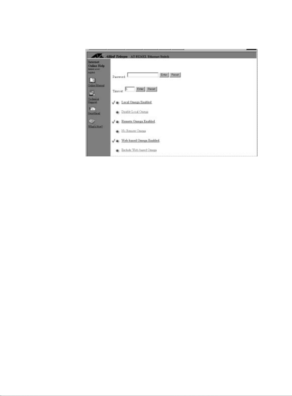
Menu:
System configuration>Omega Options
Figure 3-4
Omega Configuration Screen
Omega default options consist of the following:
Password:
Timeout :
No password is initially required to access Omega.
The default is
5 minutes
. A timeout value is one way to
protect the switch from unauthorized use in case you forget to
exit Omega and then leave the switch unattended. If you
configure a timeout value, Omega clocks the elapsed time
between the last time any key was pressed during an Omega
session. If the elapsed time exceeds the timeout value, Omega
automatically quits.
Local Omega:
The default is
enabled
. Local Omega means you
can access the management menus by connecting a terminal
or PC to the RS232 management port.
Remote Omega :
The default i s
enabled
. Remote Omeg a me an s
you can access the management menus from a remote
location by entering the switch’s MAC address, its configured
IP address, or user-assigned unique name.
Web-based Omega :
The default is enabled. Web-based Omega
means you can access the management menus by connecting
to your switch through a web browser. This feature requires a
TCP/IP network. Refer to Chapter 2,
A Web Browser
, for details on how to access the switch via the
Menu Navigation Using
World Wide Web.
3-12
Page 45

$70654#8VHU·V#*XLGH
&RQILJXULQJ#D
3DVVZRUG
&RQILJXULQJ#D
7LPHRXW#9DO XH
To configure a password
1. Select System configuration>Omega Options.
2. Enter a string of up to 20 characters in the Password field. The text string displays as a series of asterisks. The next time
you restart Omega, you must enter this password before you
can start a session. A user name is not required.
This password is not related to the download password for
downloading software to the switch (described in the section,
IP Parameters
in this chapter).
To delete a password
1. Select System configuration>Omega Options.
2. Enter a space in the Password field.
To configure a timeout value
1. Select System configuration>Omega Options.
2. Enter a value from 0 to
65,535
(in minutes) in the Timeout field.
If you enter 0, then you must always quit after a management
session. Otherwise, subsequent Telnet sessions and software
downloads to the switch will be blocked.
To delete or change a timeout value
1. Select System configuration>Omega Options> Timeout
2. Do one of the following:
To delete the current value, enter 0.
❑
To change the value, enter another value from
❑
If you enter 0, you must always quit after a management
session in order not to block subsequent remote sessions and
software downloads to the switch.
Return to Main Menu.
0 to 65,535
.
3-13
Page 46

6\VWHP#&RQILJXUDWLRQ
%DFNSUHVVXUH
Menu:
System configuration>No backpressure
Backpressure is disabled as a default.
Note
Although listed in the software, this option is not available and should remain disabled.
In half-duplex mode, the switch implements the backpressure
methodology when its input buffer is running out of resourc e s; for
example, outbound packets are traversing a single uplink port. When
backpressure is enabled, the switch simulates a collision when its
input buffers are filled up so that sending devices will defer
transmissions. These sending devices will retry transmissions
according to the Ethernet back-off algorithm. Once switch resources
are available again, it stops sending the collision signals and devices
may freely transmit again.
3-14
Page 47

7HUPLQDO#&RQILJXUDWLRQ
$70654#8VHU·V#*XLGH
97433
&RPSDWLEOH#RU
$16,
Menu:
Configuration
Omega supports two types of terminal configuration options:
For this type of terminal, the enabled options are preceded by a >
and also appear brighter.
System configuration>Terminal
VT100-compatible or ANSI (the default)
❑
Generic (dumb) terminal
❑
To use the menus in a VT100-compatible type of terminal configuration
Press
<Return>
highlighted.
Press the up (↑), down (↓), left (←), or right (→) arrow keys to
highlight the option you want, and then press
Enter the first character of the option you want. In some cases
where options have the same initial letters, enter enough
letters until the software can differentiate your choice from
the other options.
to enable the option that is already
<Return>
.
*HQHULF#+'XPE,
7HU PLQ DO
Press
<Esc>
For this type of terminal, the enabled options are preceded by a >.
to go to the previous menu.
To use the menus in a generic type of terminal configuration
Enter the initial character of the option you want, then press
<Return>
character, enter enough characters until the software can
differentiate your choice from the other options. To guide you,
the menus display the required characters in uppercase.
Press
or entering anything.
. In some cases where options have the same initial
<Return>
to go to the previous menu without selecting
3-15
Page 48

7HUPLQDO#&RQILJXUDWLRQ
Enter the letter corresponding to your choice if choices are
preceded by
A: IP address:Null (not configured)
B: Subnet mask:Null (not configured)
C: Gateway address:Null (not configured)
D: Domain Name Server:Null (not configured)
E: Default Domain Name:Null (not configured)
letters
. For example, if your choices are:
Enter A for IP address or B for subnet mask.
Enter the letter corresponding to your choice if choices are
preceded by
1: Port 1 - Room 1147
2: Port 2 - Room 1148
3:
numbers
. For example, if your choices are:
Enter 1 for Port 1 - Room 1147, 2 for Port 2 -
Room 1148, or 3 for Port 3.
7HU PLQ DO#6HWWLQJV
Data bits, stop bits, and parity:
and
No parity
are provided.
Defaults of 8 data bits, 1 stop bit,
Transmission mode: Full-duplex (echo)
travels in both directions.
Half-duplex (no echo)
in only one direction at a time.
Data rate (baud rates):
detectio n
❑
❑
❑
❑
❑
❑
❑
❑
. You can also select from the following fixed baud rates:
19200 bps
9600 bps (recommended setting for fixed baud rate)
4800 bps
2400 bps
1200 bps
600 bps
300 bps
150 bps
The default is
automatic baud rate
, the default, means data
means data travels
3-16
75 bps
❑
Automatic baud rate detection
❑
Return to Main Menu.
Page 49
9LUWXDO#/$1#&RQILJXUDWLRQ
$70654#8VHU·V#*XLGH
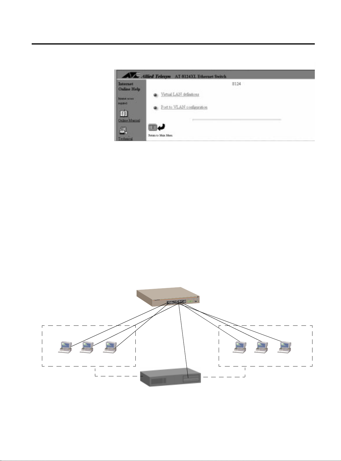
Menus:
Virtual LANs
Figure 3-5
Virtual LANs M enu
This switch su pports port based VLANs only.
By default, the switch has one VLAN (all ports’ VLAN assignment
showing as
Default VLAN
) and one spanning tree. In most
situations, users find the defaults acceptable and do not require
further configuration; however, your network may require assigning
end stations into logical groupings, regardless of their physical
location. You can group your end stations logically through VLANs.
Information exchange is confined within the members of a given
VLAN. A VLAN constitutes one broadcast domain; therefore,
broadcast packets from an end station only go to other stations
within the same VLAN.
VLAN 1
VLANs cannot communicate with each other through the switch;
they require a router to do this (Figure3-6).
S
U
T
A
T
S
-232
S
R
T
R
O
P
L
A
IN
M
Y
R
IT
E
T
IV
T
C
A
T
R
O
P
X
-T
E
S
A
/ 100B
-T
E
S
A
10BASE-T / 100BASE-TX
FAST ETHERNET SWITCH
10B
Router
Figure 3-6
AT-8124XL
VLAN 2
VLAN Example
3-17
Page 50
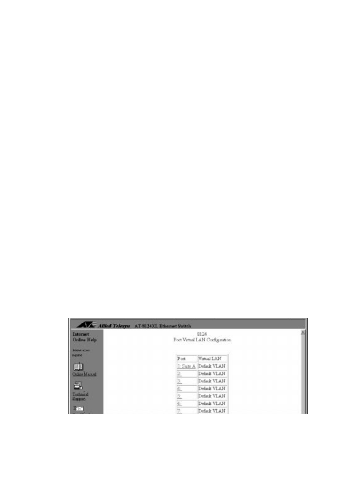
9LUWXDO#/$1#&RQILJXUDWLRQ
The number of configurable VLANs depends on the switch’s port
count, including the RS232 management port and any optional
uplink ports. The AT-8118 and AT-8118XL each have 16 base ports,
with none, one, or two optional uplink ports, for a total count of 16,
17, or 18 ports. The AT-8124XL has 24 ports. The AT-8126XL has 24
base ports wih none, one, or two optional uplink ports, for a total
count of 24, 25, or 26 ports.
Advantages of Using VLANs
You have the flexibility of grouping workstations logically or
❑
functionally, regardless of their physical location on the
network.
You can change VLAN memberships anytime by software
❑
configuration without moving the workstations physically, or
change group memberships by simply moving a cable from
one port to another.
The examples used in the procedures that follow will illustrate a
simple yet practical way of “splitting” a 24-port switch into two
virtual switches by configuring two VLANs.
In these procedures, you will:
Configure a 24-port switch into two VLANs,
❑
Assign ports 1-12 to
❑
and ports 13-25 to
East
East
West
and
West.
. The RS232
management port is Port 25.
To view the ports’ default VLAN configuration, select Virtual
LANs>Port to VLAN configuration. The screen shows all
ports belonging to
Default VLAN
. See Figure3-7 for an example of
the list (partially shown).
3-18
Figure 3-7
Switch Ports’ Default VLAN Configuration
Page 51
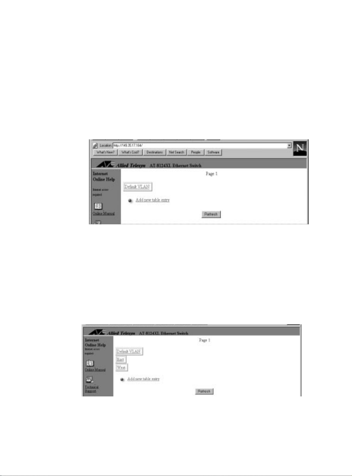
$70654#8VHU·V#*XLGH
'HILQLQJ#WKH
9/$1V
Menu:
Virtual LANs
To define VLANs
In this procedure, you will configure two VLANs:
1. Select Virtual LANs from the main menu to display the Virtual LAN Menu.
2. Select Virtual LAN definitions to display the VLAN Definition Menu.
As this screen shows, there is one VLAN on the list:
.
VLAN
East
and
West
Default
.
Figure 3-8
VLAN Definition Menu
3. Select Add new table entry to display the next screen.
4. Enter the name
in the type-in field.
East
5. Repeat the procedure from the beginning to define another
VLAN,
West
.
6. Go to the VLAN Definitions Menu to display the VLANs you
just defined. Your VLAN list may now look like the following
screen:
The screen displays up to four VLANs and expands to another
page as the VLAN list grows. VLANs
East
and
West
don’t have
ports assigned at this time.
3-19
Page 52

9LUWXDO#/$1#&RQILJXUDWLRQ
To delete or rename VLANs
1. Select Virtual LANs>Virtual LAN definitions to
display the list of VLANs similar to the following screen (four
VLANs are defined for illustration purposes):
2. Select the VLAN name you want, for example,
To delete the name from the list, enter a single asterisk (*).
❑
To rename the VLAN, enter the new name.
❑
You cannot delete
Default VLAN
but you can rename it. If you
Upper Deck
delete a VLAN that has ports assigned to it, the ports’ VLAN
assignments revert to switch’s
Default VLAN
.
Return to Main Menu.
; then:
3-20
Page 53
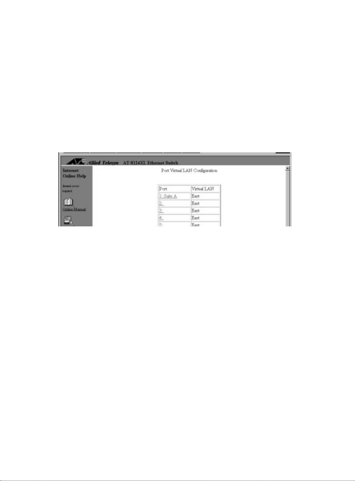
$70654#8VHU·V#*XLGH
$GGLQJ#3RUWV#WR
WKH#9/$1
Menu:
In this procedure, y ou will assign Ports 1-12 to
Virtual LANS>Port to VLAN configuration
.
East
1. Select Port to VLAN configuration from the Virtual
LANs menu to get the list of ports and their VLANs, similar to the
screens in Figure3-7, on page 3-18.
2. Select the port number, for example, 1, to get the port’s VLAN
configuration screen that displays a list of defined VLANs.
3. Select
East
.
4. Return to the Virtual LAN Menu and repeat the procedure to
assign Ports 2 through 12 to
East
.
The ports’ VLAN definition is now as follows:
Figure 3-9
5. Repeat the procedure to assign Ports 13 through 25 to
Ports to VLAN
East
West
When adding ports to VLANs, consider the following:
If you are managing the switch from a remote station, make
❑
sure that station and the manageme nt port (Port 25 in thi s
example) belong to the same VLAN.
Note the port you are using for your network connection, and
❑
make sure this port belongs to the same VLAN as your
management port. For example, if Port 13 is your connection
to the backbone, Port 13 and Port 25 must belong to the same
VLAN.
.
3-21
Page 54

:KHUH#WR#*R#1H[W
To delete a port from a VLAN or change a port’s VLAN assignment
1. Select Port VLAN configuration from the Virtual
LANs menu to display the port list with VLAN assignments
(similar to Figure3-7).
2. Select the port number you want to delete or change. The screen displays the port’s VLAN configuration and a list of
available VLANs (similar to Figure 3-9).
3. Do one of the following:
To reassign the port to another VLAN, select the new VLAN
❑
name from the list.
:KHUH#WR#*R#1H[W
To delete the port from a VLAN, select
❑
Default VLAN
from the
list.
The screen displays the list of ports with the updated VLAN
assignment.
Return to Main Menu.
Proceed to Chapter 4 to operate and monitor and operate the switch.
3-22
Page 55

&KDSWHU#7
0RQLWRULQJ#DQG#$GPLQLVWUDWLRQ
This chapter describes the procedures to monitor and operate y our
switch.
Monitoring topics are as follows:
❑
Activity Monitor
❑
Connection to a Remote Switch
❑
Connectivity Verification (Ping)
❑
Ethernet Statistics
Administration topics are as follows:
❑
MAC Address Table
❑
Software Downloads
on page4-2
on page 4-5
on page4-11
on page4-17
on page 4-3
on page4-4
4-1
Page 56
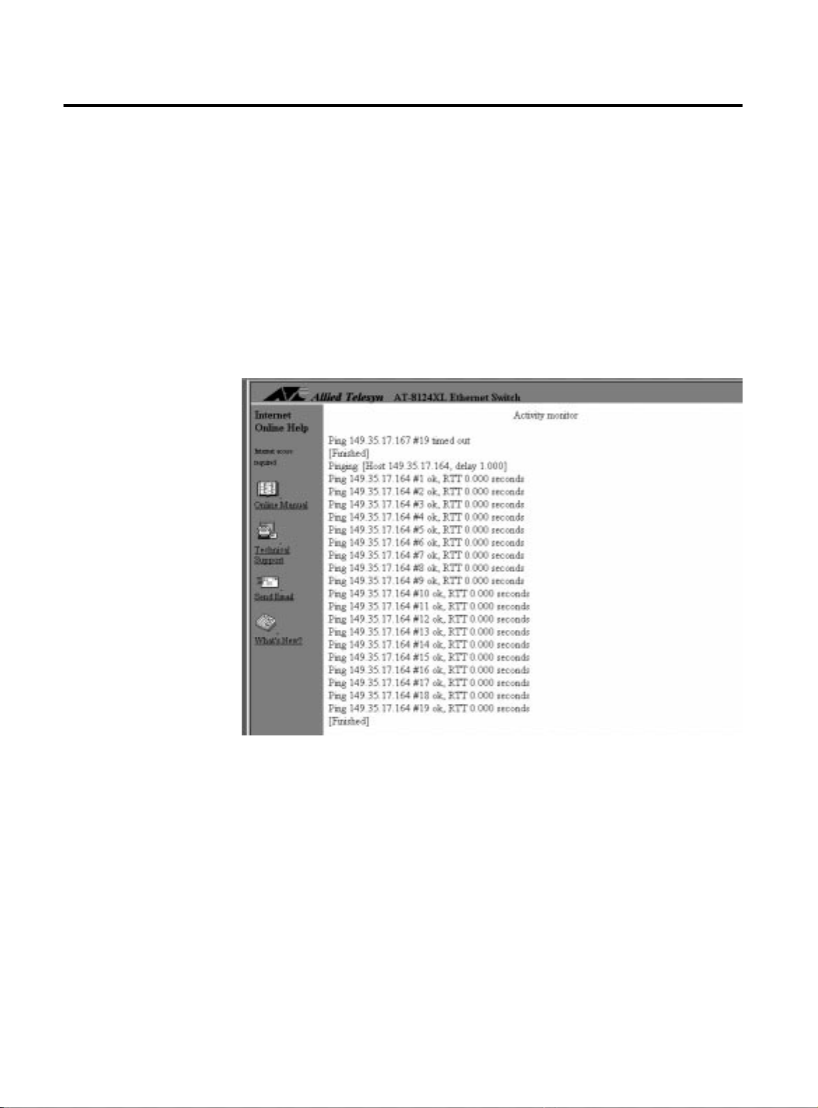
$FWLYLW\#0RQLWRU
$FWLYLW\#0RQLWRU
Menu:
Administration>Activity Monitor
The Activity Monitor option is useful in troubleshooting or in
monitoring switch activity, if any.
The activity monitor automatically activates when you download
software to switches on the network (System
administration>Broadcast updated software to
all systems).
Figure4-1 shows another switch activity displayed by the monitor,
that is, the results of
commands issued from the switch.
ping
4-2
Figure 4-1
Activity Monitor
Page 57

&RQQHFWLRQ#WR#D#5HPRWH#6ZLWFK#
$70654#8VHU·V#*XLGH
Menu:
Administration>Connect to a remote system
This option allows you to use a switch to connect to and manage
another switch from Omega. This feature is only available if you are
connected to the switch for a local software management session
using the RS232 port.
1. Select Administration>Connect to a remote system.
2. Specify the switch by one of the following methods: By its user-assigned name enclosed in single quotes, in the
❑
format
By its IP address, in the format
❑
By its Ethernet (or MAC) address, in the format
❑
‘name’
x.x.x.x
xxxxxx xxxxxx
The switch’s MAC address is printed above the switch’s RS232
management port on the front panel.
Once the information is validated and the connection to the
remote switch is opened, you immediately get that remote
switch’s Omega main menu. You may then use Omega to
configure the remote switch and run diagnostics.
The only option not available on the remote switch is
Connect to a remote system from the
Administration menu. The same is true if you used
Telnet.
3. Select Quit from the main menu when you are done.
Note
It is important that you select Quit after the Omega session.
Otherwise, you may block other sessions or software downloads via
the network to the remote switch. Refer also to Chapter 3,
Configuring Omega
, for information on using a timeout value.
4-3
Page 58
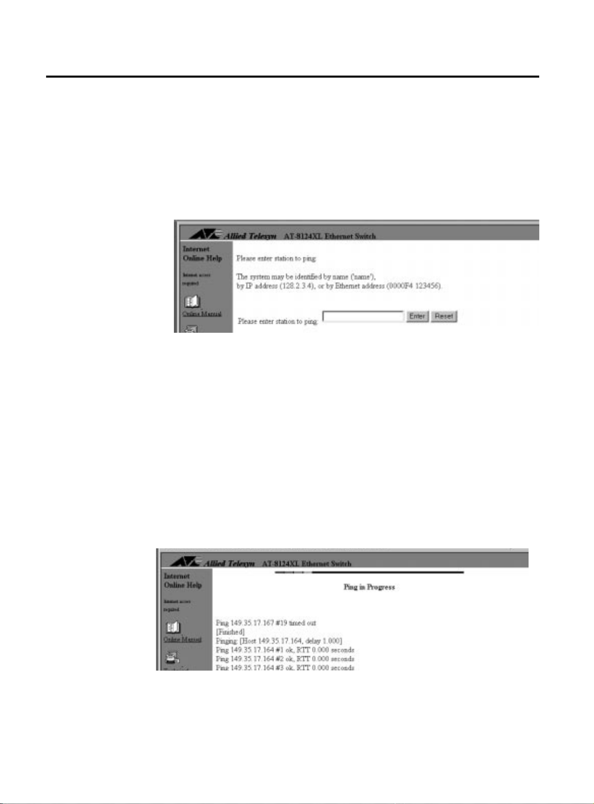
&RQQHFWLYLW\#9HULILFDWLRQ#+3LQJ,
&RQQHFWLYLW\#9HULILFDWLRQ#+3LQJ,
Menu:
The
Administration>Ping a remote system
command enables you to test if an end system can be
ping
reached by sending it an Internet control message protocol (ICMP)
echo request. If the system is connected to the network, it sends a
reply to the requesting system.
1. Select Administration>Ping a remote system to see the following display:
Figure 4-2
Ping Menu
2. Specify the system with one of the following methods:
By its user-assigned name, enclosed in single quotes, in the
❑
format
By its IP address, in the format
❑
By its Ethernet (or MAC) address, in the format
❑
‘name’
x.x.x.x
xxxxxx xxxxxx
The switch’s MAC address is printed above the switch’s RS232
management port on the front panel. The activity monitor
reports the results of the
command, shown in Figure 4-3
ping
as an example.
Figure 4-3
Ping Results
4-4
Return to main menu.
Page 59

(WKHUQHW#6WDWLVWLFV
$70654#8VHU·V#*XLGH
1DYLJDWLQJ#WKH
6WDWLVWLFV#*UDSKV
0HQXV
Menu:
Ethernet Statistics
You can view statistics on received and transmitted frames in two
ways:
At the switch level, where you see the total of each frame type
❑
on all ports taken together; or
At the port level, further broken down into:
❑
—Per port, all frame types
—Per frame type, all ports taken together
Statistics are a tool for diagnosing a problem and isolating it to a
specific port. You can view graphs that show information on the
switch as a whole. From this total picture, you have the option to
view statistics on a per-frame type or a per-port basis.
Displaying various statistics graphs does not require you to go
through a hierarchy of menus. Within a particular graph, you can
select to view statistics on a frame type, a port, or the entire system.
To illustrate, refer to Figure4-4; it is the first graph Omega displays
when you select Ethernet Statistics from the main menu.
Figure 4-4
Graph of Received Frames, Switch Level
4-5
Page 60

(WKHUQHW#6WDWLVWLFV
5HFHLYHG
To view received statistics at the switch level
6WDWLVWLFV
Select Ethernet Statistics from the main menu to
display the Receive Statistics Graph similar to
Figure 4-2.
The graph shows the types of frames the switch has received
over a period since the switch’s last reset or since someone has
last set the counters to zero.
See Table 4-1 for a definition of received frames.
Table 4-1
Frame Type Description
Received Good Frames Total number of frames received by the switch since the last reset
Filtered Fr ames Frames received by the switch but not forwarded because the
destination is within the same LAN segment, therefore, the frame
was already seen by all nodes on the segment
Broadcasts Frames received by the switch destined for
network, excluding multicast frames
Received Ethernet Frames
nodes on the
ALL
Multicasts Frames received by the switch destined for multiple but specific
addresses, excluding broadcast frames
CRC Errors Frames with a cyclic redundancy check (CRC) error but with the
proper length (64-1518 bytes)
Alignment Errors Frames with a non-integral number of bytes, that is, frame length in
bits are not evenly divisible by 8, but with the proper length (641518 bytes)
Undersized Frames Frames less than the minimum specified by IEEE 802.3 (64 bytes
including the CRC); also called runts
Fragments Total undersized frames, frames with alignment errors, and frames
with FCS errors (CRC errors)
Long Frames Frames exceeding the maximum specified by IEEE 802.3 (1518 bytes
including the CRC)
4-6
Page 61
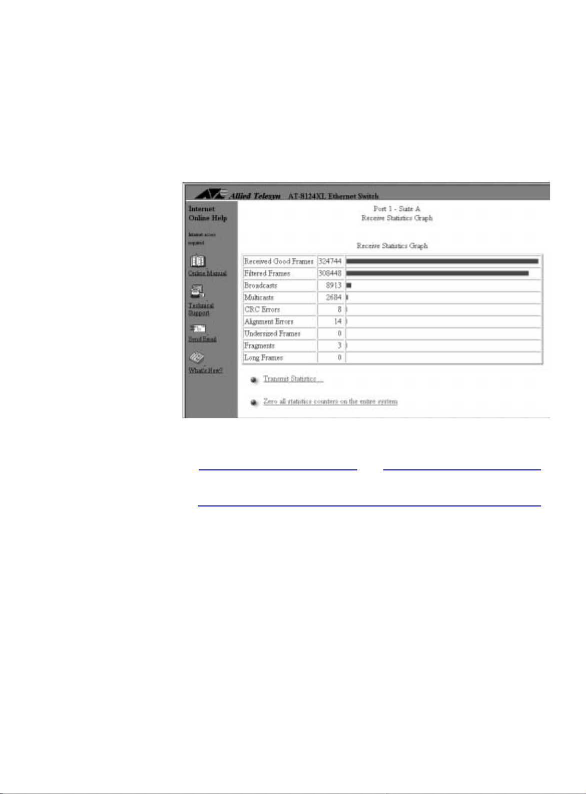
$70654#8VHU·V#*XLGH
To view received statistics per port
1. Select Individual Port Overview from the Receive
Statistics Graph screen to display a list of ports.
2. Select a port number, for example, Port 1. The screen displays a graph at the port level, similar to
Figure 4-5.
Figure 4-5
Graph of a Port’s Received Frames
Note
You may also view an individual port’s receive statistics through the
Port status and configuration>
<port number>
menu.
To view received statistics per frame type
Select a frame type (e.g., Filtered Frames, Forwarded
Frames, and so on) from the switch-level graph (Figure 4-4
on page 4-5) that lists all frames.
Omega displays that frame’s statistics according to ports,
similar to Figure4-6.
Return to main menu.
4-7
Page 62
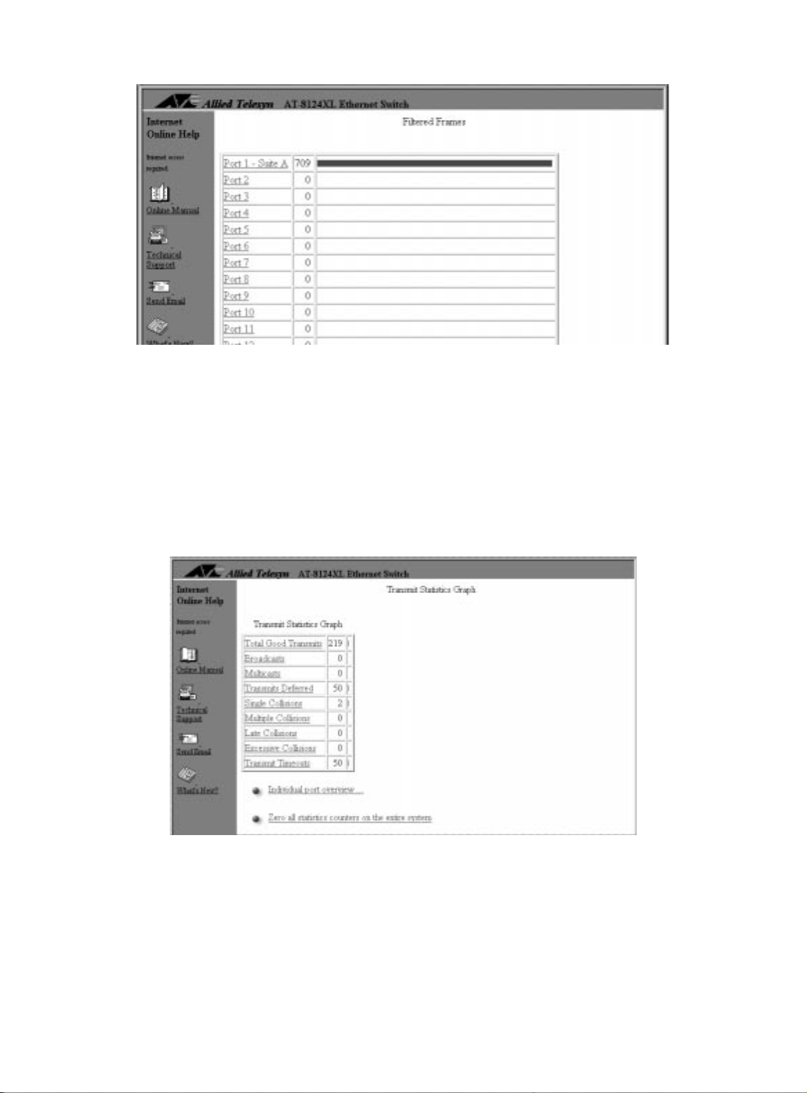
(WKHUQHW#6WDWLVWLFV
7UDQVPLW#)UDPHV
Figure 4-6
Menu:
Ethernet Statistics>Transmit Statistics
Sample Graph of a Single Frame Type on All Ports
To view transmit statistics
Select Transmit statistics to display the Transmit
Statistics Graph similar to Figure 4-7.
4-8
Figure 4-7
Sample Graph of Transmitted Frames
The graph shows the types of frames the switch has
transmitted over a period since the switch’s last reset or since
someone has set the counters to zero.
Page 63

$70654#8VHU·V#*XLGH
Expect transmit errors to be very small. The switch may receive
a number of bad frames, but the switch drops those and sends
only good frames.
See Table 4-2 for a definition of transmit frames.
Table 4-2
Transmit Ethernet Frames
Frame Type Description
Total good transmits Total frames transmitted by the switch without errors since the last
reset
Broadcasts Frames forwarded by the switch destined for
nodes on the
ALL
network, excluding multicast frames
Multicasts Frames forwarded by the switch destined for multiple but specific
addresses, excluding broadcast frames
Transmits deferred Frames whose transmission has been deferred by the switch due to
lack of resources; they are not stored in the buffer and eventually
dropped
Single collision Frames from two ports that collided because they were sent at the
same time; considered normal
Multiple collisions The same frames collide more than once; they are expected to be
far less than single collisions and may indicate a problem with the
sending devices
Late collisions Collisions that occur after 64-byte times of the frame had elapsed
Excessive collisions A frequency of frame collisions detected by the port that causes the
interface to fail to transmit frames
Transmit timeouts Number of times the switch has stopped trying to transmit due to
collisions
To view transmitted statistics per port
1. Select Individual Port Overview from the Transmit
Statistics Graph screen to display a list of ports.
2. Select a port number to view a graph of that port’s transmit statistics.
4-9
Page 64

(WKHUQHW#6WDWLVWLFV
,QWHUSUHWLQJ#WKH
*UDSKV
The statistics graphs show the types of received and transmitted
frames since the last time the counters or the switch were reset. The
counters and the graph dynamically increment as the switch
processes frames over a period of time.
When the individual counters reach a maximum of 232 (over 4
billion), they reset to zero. Because each counter resets
independently; your graph may become inaccurately skewed over
time; therefore, you need to reset the counters to get a new baseline
on frame statistics.
The graphs help you visually monitor the pr oportion of good and
bad frames the switch has detected. Good frames consist of filtered
and forwarded broadcasts and multicasts. Bad frames are runts and
long frames, or those with CRC or alignment errors. It is normal to
have a number of error packets now and then. If the network seems
to be “slow,” this graph is one of the areas you can check to help
isolate the problem.
To use the graphs as monitoring and diagnostics tools
1. Display any of the Ethernet statistics graphs by selecting
Ethernet statistics from the main menu.
2. Observe the counters and the graph.
3. Identify and then fix the problem. Note that the problem may be external to the switch, and the
statistics may just indicate an error condition somewhere on
the network you need to fix. You may also need additional
monitoring devices specifically designed for that purpose,
such as a network analyzer, to identify the problem.
4. Select Zero all statistics counters on the entire
system from any of the Statistics screens after fixing the
problem.
You need to reset counters to get a new baseline. That is
because the counters and graphs still depict the information
during the error condition and will continue to increment
from there until you reset the counters.
Return to main menu.
4-10
Page 65

0$&#$GGUHVV#7DEOH
$70654#8VHU·V#*XLGH
Menu:
MAC Address Table
Figure 4-8
MAC Address Menu
The MAC address table (also referred to as the forwarding table) is a
snapshot of
source
MAC addresses that the switch has learned and
stored in its volatile memory . The switch can store up to 16K
addresses. The information on the table dynamically changes as
packets bearing source addresses appear on any port.
The table flows into a second page as more addresses are detected
by all ports.
The table ages out MAC addresses after 300 seconds (5 minutes) as a
default. This means if a MAC address listed on the table does not
reappear on any port within the aging time, that address is deleted. If
you reset the switch or remove power, the table clears but
immediately gets updated as soon as the switch is operational and
the ports start to detect MAC addresses in incoming packets.
Static MAC addresses are not affected by aging time, loss of power, or
switch resets. This topic is described later in this section.
4-11
Page 66

0$&#$GGUHVV#7DEOH
To display the MAC address table
1. Select MAC Address Table from the main menu.
2. Select Show all MAC addresses to get a screen similar to
Figure 4-9.
Figure 4-9
Sample MAC Address Table
To display the MAC address table sorted by port
1. Select MAC Address Table>By port MAC addresses to display a list of ports.
2. Select a port number from the list to display a table similar to
Figure 4-10:
4-12
Figure 4-10
MAC Address Table Sorted by Port
The table flows into a second page as the port detects more MAC
addresses.
Page 67
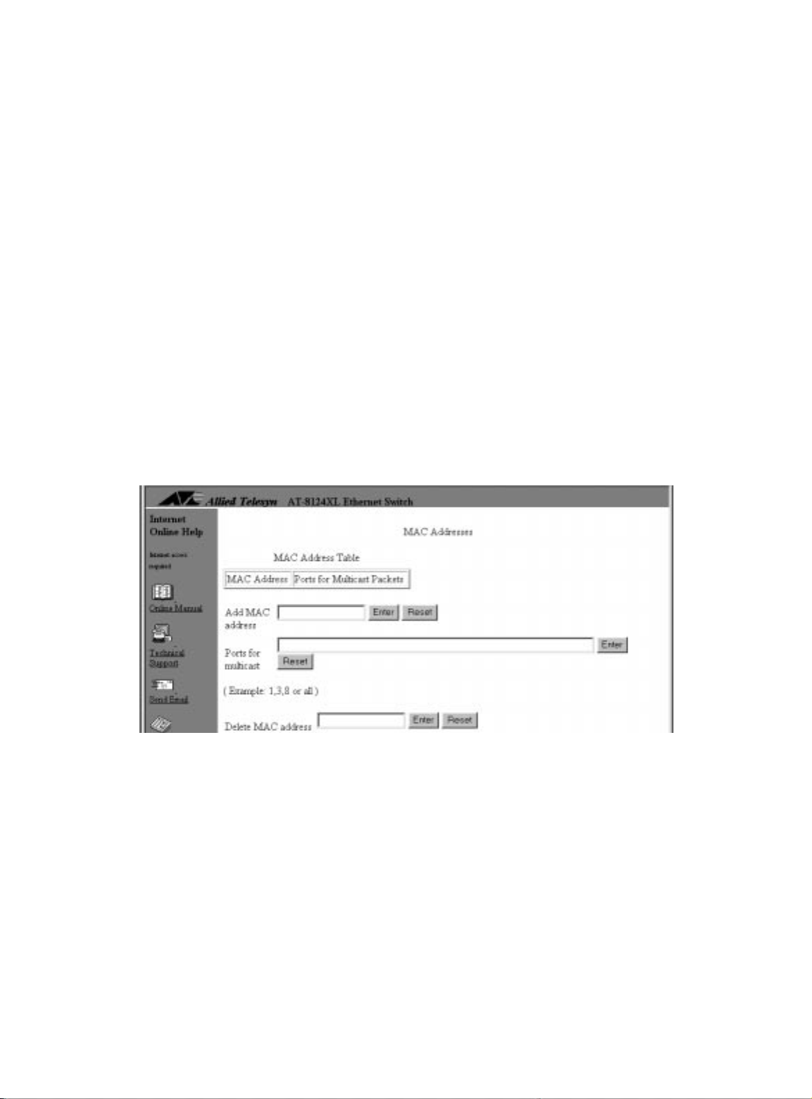
$70654#8VHU·V#*XLGH
0XOWLFDVW#$GGUHVV
Menu:
MAC Address Table>Multicast addresses
A broadcast is a transmission that sends copies of a packet to all end
stations on the network. A multicast is a special form of broadcast
where copies of a packet are delivered to a specific group of end
stations.
A multicast address is a destination address. You can configure 10
(ten) multicast addresses per switch. Configuring a multicast address
in Omega enables you to restrict certain packets to only go to a
group of ports. For example, you may have a server running some
special applications and you do not want all end stations in the
network to receive packets from this server.
To configure a multicast address
1. Obtain your server’s MAC address; this might be the server with restricted applications.
2. Select MAC Address Table>Multicast addresses to display the following:
Figure 4-11
Multicast Address Menu
3. Enter the server’s Mac address from Step 1 as the multicast
address.
4. Enter one or more port numbers that are to receive multicast
packets from this server. Use one of the following formats:
to enter a single port
1
3, 8, 22
all
to enter multiple ports
to enter all ports
4-13
Page 68

0$&#$GGUHVV#7DEOH
Any port may have more than one multicast address
associated with it. The number of multicast addresses you can
configure is limited to ten (10) per switch.
Omega confirms a successful add with the following message:
To change ports for multicasts
To change the ports for a multicast address, for example, if you want
to increase the number of ports from 5 to 6, start all over by following
the procedure to configure a multicast address and add all six ports.
To delete a multicast address
1. Select MAC Address Table>Multicast addresses to
display the menu in Figure 4-11 on page 4-13.
2. Enter the MAC address you want to delete in the Delete MAC address field.
After you delete a multicast address, wait and the display
updates with the changed information.
4-14
Page 69
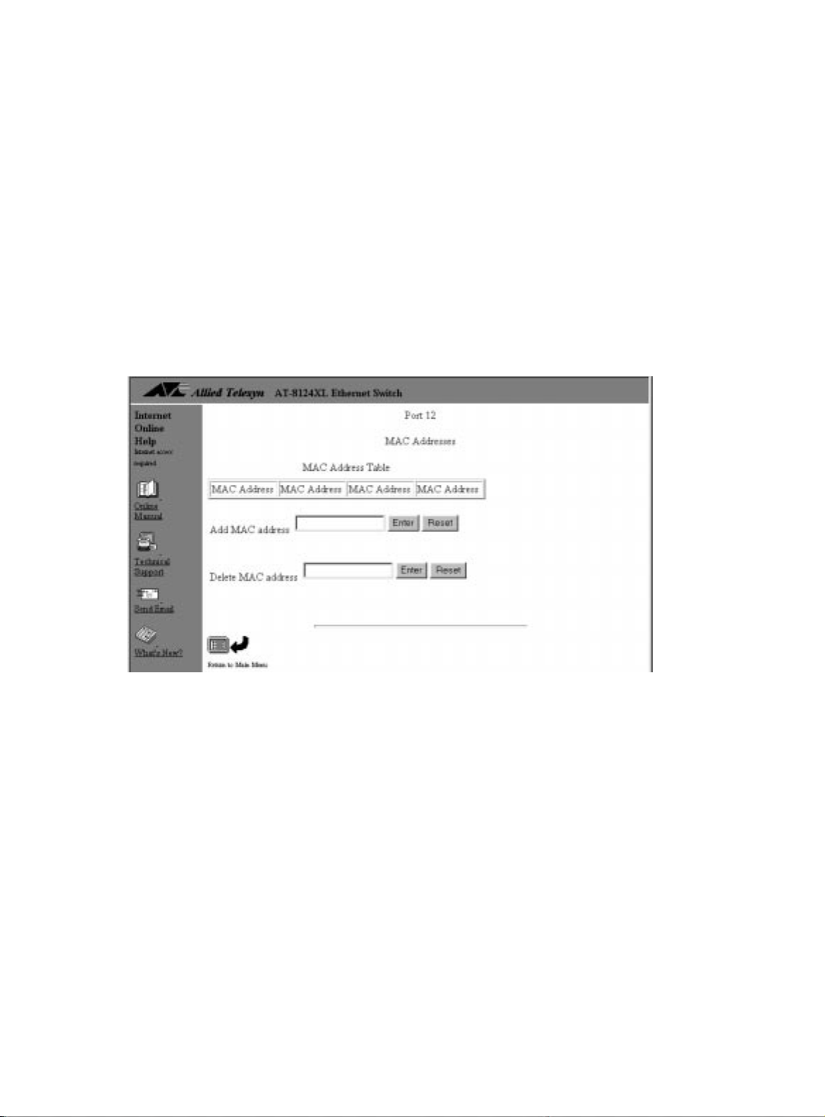
$70654#8VHU·V#*XLGH
6WDWLF#0$&
$GGUHVVHV
Menu:
MAC Address Table
The static MAC table also includes any configured multicast
addresses. Entering static MAC addresses ensures certain devices
access to the switch’s ports, because aging time, pow e r failures, or
switch resets do not affect the static MAC table.
To enter a static address per port
1. Prepare a list of your devices’ MAC addresses and their port assignments.
2. Select MAC Address Table>Per port static MAC
addresses to display a similar screen (no MAC addresses have
been configured):
Figure 4-12
Adding Static MAC Addresses to the Ports
3. Enter a MAC address in the Add MAC address field. Use following format:
XXXXXX XXXXXX
After adding a static MAC address, wait and the display updates with the changed information; if necessary, return to the main menu and select MAC Address Table>All static MAC addresses to display the updated table.
The static MAC address appears on the Static MAC table. You
can configure only one static MAC address per port.
4-15
Page 70

0$&#$GGUHVV#7DEOH
To view the static MAC address table
Select MAC Address Table>All static MAC
addresses.
The display is for viewing purposes only.
To clear the static MAC address table
1. Select MAC Address Table>Clear static MAC table.
2. Select Yes to confirm or No to cancel. After clearing a static MAC address, wait and the display
updates with the changed information; if necessary, return to
the main menu and select MAC Address Table>All MAC
addresses to display the updated table.
6ZLWFK·V#0$&
$GGUHVV#/RFDWLRQ
If you want to know your Allied Telesyn switch’s MAC address:
Locate the MAC address label directly above the RS232
❑
management port on the switch’s front panel, or
Select Administration>Diagnostics to read the MAC
❑
address from the screen
Return to Main Menu.
4-16
Page 71

6RIWZDUH#'RZQORDGV
$70654#8VHU·V#*XLGH
You can download software upgrades from one switch to one or
more switches on the network using Omega; or download software
via the trivial file transfer protocol (TFTP) from a TFTP server.
The switches described in this guide initially use a factory-configured
default password,
not need to manually enter this password to download software
successfully . Software downloads do not require y ou to be ph ysically
at the destination switches.
ATS21
, to authorize software downloads. You do
&RQGLWLRQV#IRU
1HWZRUN
'RZQORDGV
8VLQJ#7)73
Omega uses the trivial file transfer protocol (TFTP) of the TCP/IP
protocol suite to download software to other switches, whether or
not your network uses TCP/IP.
The switch can download software to other switches of the sam e
product family within the following conditions:
The switches must be directly connected to the same network
❑
cable or joined by switches, bridges, or routers. If joined by
routers, the gateway addresses in both source and destination
switches must be properly configured.
All switches receiving the same software must use the same
❑
download password as the source (default,
Chapter 3,
If you have TFTP, you can use TFTP commands to download an image
file from the switch that has the upgraded software.
TFTP platforms vary. Some have graphical user interfaces while
others require you to enter commands. Consult your TFTP
documentation for the commands. When using the TFTP
are on the destination switch) or
command, use the following variables:
IP Parameters
, on page3-2.
(if you are on the source switch)
put
ATS21
). See
(if you
get
Image file name:
www .alliedtelesyn.com
IP address:
destination of the image file.
Download password:
uppercase.
File type:
The file type is
Get the latest from Allied Telesyn’s website at
.
This is the IP address of the switch that is the source or
The default download password is
octet
ATS21
.
in
4-17
Page 72

6RIWZDUH#'RZQORDGV
'RZQORDGLQJ
6RIWZDUH#WR#2QH
6ZLWFK
Menu:
Administration>Update software in another
system
Follow this procedure in order to:
Download software to another switch on the network without
❑
physically being at the destination switch
Ensure that all the switches on the network you intend to
❑
upgrade will be upgraded, since you will be manually
downloading software one switch at a time
1. Select Administration>Update software in another
system.
2. Specify the system with one of the following methods:
By its user-assigned name, enclosed in single quotes, in the
❑
format
By its IP address, in the format
❑
By its Ethernet (or MAC) address, in the format
❑
‘name’
x.x.x.x
xxxxxx xxxxxx
The switch’s MAC address is printed above the switch’s RS232
management port on the front panel.
The screen immediately turns on the Activity Monitor
screen and displays the information as the destination switch
requests and then receives the software.
Repeat this procedure to download software to another switch on
the network.
4-18
Page 73

$70654#8VHU·V#*XLGH
'RZQORDGLQJ
6RIWZDUH#WR#$OO
6ZLWFKHV
Menu:
Administration>Broadcast updated software
to all systems
Plan a software broadcast update during times when your network is
not busy.
1. Select System administration>Broadcast updated software to all systems.
The switch announces the availability of the software to all
switches belonging to the same series; in turn, the switches
that need the upgrade respond by sending back a “request”
message.
The screen immediately turns on the Activity Monitor
screen and displays the information as switches on the
network request and then receive the software.
Note
You cannot undo this command once executed.
You may go to menus without interrupting the software
download.
If you have many switches requesting the download, not all of them
may receive it especially if the network is busy. Repeat the procedure
to ensure all switches receive the software upgrade.
Note
Switches with different download passwords will not receive the software download.
4-19
Page 74
6RIWZDUH#'RZQORDGV
8VLQJ#;0RGHP
WR#'RZQORDG
6RIWZDUH
Menu:
Administration>XModem software update to
this system
Omega supports software downloads to the switch using XModem.
It is assumed that you have the required setup to support this type of
file transfer. This menu is not available through the web browser,
because the Xmodem transfer occurs through the switch’s RS232
management port.
Use the following procedure to set up your switch for an XModem
transfer.
1. Launch Omega’s terminal interface.
2. Select Administration>XModem software update to
this system to display the following:
Ready to receive software upgrade via XModem.
Warning: During software update Management activity is
disabled.
Do Xmodem update now? (Yes or No):
3. Enter
and wait for the following message:
Yes
The system host is now ready for download.
Please start your XModem transfer.
4. Initiate the download from your XModem host. The Xmodem host displays the download in progress, similar
to the following message:
Stop
Sending: ATS21 Retries: 0
4-20
Page 75

&KDSWHU#8
'LDJQRVWLFV
This chapter describes the following topics:
❑
Running Diagnostics
❑
Resetting Statistics Counters
❑
Resetting the Switch
❑
Getting Help
Also see the
Ethernet Switches Installation Guide
different ways to diagnose error conditions by interpreting the LEDs
on the switch ’s front and back panels.
AT-8118, AT-8118XL, AT-8124XL, and AT-8126XL F ast
on page5-5
on page5-2
on page5-3
on page 5-4
that explains in detail the
5-1
Page 76

5XQQLQJ#'LDJQRVWLFV
5XQQLQJ#'LDJQRVWLFV
Menu:
Administration>Diagnostics
Select Diagnostics from the Administration menu to display
the Diagnostics screen. Figure5-1 shows a sample
Diagnostics screen.
Figure 5-1
The Diagnostics Screen
The Diagnostics menu allows you to run a limited set of
diagnostic tests on the switch. There are only two results: Good or
Failed.
You also see the following information:
The switch model and version number
❑
The switch’s MAC address
❑
The software model and version number
❑
The type of MDA (denoted by the screen as appliqué), if
❑
installed
The time the switch has been up and running since the last
❑
reset
5-2
Page 77

5HVHWWLQJ#6WDWLVWLFV#&RXQWHUV
$70654#8VHU·V#*XLGH
Menu:
Ethernet statistics>Zero all statistics on
the entire system
You reset statistics counters because:
The counters no longer reflect the current information.
❑
For example, disabling a port to fix a problem does not
reset its counters. After the error clears and you manually
re-enable the port, you may want its statistics to
accumulate from a fresh start. Otherwise, the counters and
the graph not only still reflect information associated with
the error condition; the counters continue to increment
from the wrong baseline.
As each frame type reaches the maximum of 2
❑
billion), the statistics for that frame type resets to zero. Once
this happens, the counters and graph become inaccurately
skewed.
To reset switch (system) counters
32
(over 4
1. Select Ethernet Statistics from the main menu to display the Receive Statistics graph.
2. Select Zero all statistics on the entire system.
Both Receive and Transmit counters and graphs are reset to zero.
5-3
Page 78

5HVHWWLQJ#WKH#6ZLWFK
5HVHWWLQJ#WKH#6ZLWFK
Menu:
Administration>Reset and restart the
system
You reset the switch:
As a first attempt to fix an error condition; for example, the
❑
FAULT LED is on
To download software through a modem
❑
To reset all statistics counters to zero
❑
To reset the switch
Reset the switch in
Select Administration>Reset and restart the
system;
Press
<RESET>
Disconnect the power cord, then reconnect it.
of three ways:
one
on the switch’s front panel; or
The switch first undergoes a Power-on Self Test (POST) process that
takes only a few moments; then the switch becomes operational
again.
5-4
Page 79

*HWWLQJ#+HOS
$70654#8VHU·V#*XLGH
Contact Allied Telesyn’s technical support at the company’ s website
at
www .alliedtelesyn.com
. Be prepared to provide the following
information:
Switch model number
❑
Serial number
❑
Software version
❑
A description of the problem
❑
Contact telephone number
❑
Contact name
❑
5-5
Page 80

Page 81

$SSHQGL[#$
6SDQQLQJ#7UHH#&RQFHSWV
This appendix provides a brief explanation of the Spanning Tree
Algorithm as implemented by Allied Telesyn on the switches.
For detailed information on the operation of the Spanning T ree
Algorithm, consult Section 4 of IEEE Std 802.1D, ISO/IEC 10038: 1993.
The AT-8118, AT-8118XL, AT-8124XL, and AT-8126XL switches, which
run the AT-S21 software, implement the IEEE 802.1D Spanning Tree
Protocol (STP). The STP prov ides a network with robustness and
allows network administrators to easily change their network
topology. Its implementation reduces complex network topologies
(networks with multiple paths between source and destination
nodes) to a single active topology. This tech nique guarantees that
loops do not occur between source and destination nodes of the
network. Loops are eliminated by placin g some of the r edundant
ports in a “blocking” state, in which they do not forward packets but
continue to execute the protocol. If the network topology changes,
for example by the failure, removal, or addition of an active network
node, a “blocked” port may be included in the new active topology
and begin forwarding frames.
A-1
Page 82

6SDQQLQJ#7UHH#3URWRFRO#)HDWXUHV
6SDQQLQJ#7UHH#3URWRFRO#)HDWXUHV
The switches implement the following STP features:
Compensate automatically for the failure, removal, or addition
❑
of any bridge in an active data path.
Achieve port changes in short time intervals, which
❑
establishes a stable active topology quickly with a minimum
of network disturbance.
Use a minimum amount of communications bandwidth to
❑
accomplish the operation of the STP.
Reconfigure the active topology in a manner which is
❑
transparent to stations transmitting and receiving data
packets.
Manage the topology in a consistent and reproducible
❑
manner through the use of STP parameters.
A-2
Page 83

6SDQQLQJ#7UHH#3URWRFRO#3DUDPHWHUV
Several configuration parameters control the operation of the
Spanning Tree Protocol. TableA-1 describes the parameters and lists
each parameter’s default settings for the switch. The port numbers
include the twenty-four 10Base-T or 100Base-TX ports.
$70654#8VHU·V#*XLGH
Table A-1
Spanning Tree Protocol Parameters
Parameter and Description Default
Bridge Group Address
N/A
Unique MAC group address, recognized by all
bridges in the network
Bridge Identifier
Identifier for each bridge, consisting of two
32768
(bridge priority)
parts: a 16-bit bridge priority and a 48-bit
network adapter address. Ports are numbered
in absolute numbers; from 1-n for a multi-port
switch including optional expansion ports, if
any. The network adapter address is the same
address as the first port of the bridge.
Port P ri or ity 128
Port Cost
The spanning tree algorithm calculates and
100 for 10 Mbps ports
10 for 100 Mbps ports
ensures that an active topology generates
minimal path costs.
A-3
Page 84

6SDQQLQJ#7UHH#2SHUDWLRQ
6SDQQLQJ#7UHH#2SHUDWLRQ
When spanning tree is enabled for the first time; or when the
network topology changes due to a failure, the addition, or remo val
of a component, the spanning tree algorithm automatically sets up
the active topology of the current network.
Communication between bridges -
Periodically, all devices running
STP on a network transmit packets to each other through the Bridge
Group Address which all bridges share. When a bridge receives a
packet sent to the Bridge Group Address, the bridge’s STP processes
the packet. The packet is ignored by application software and other
LAN segments. Bridges communicate between each other in order to
determine the
root bridge
Selecting a root bridge and des ig nated bridges -
.
During
communication between bridges, one bridge is determined to have
the lowest bridge identifier. This bridge becomes the root bridge.
After the root bridge has been selected, each LAN segment looks for
the bridge that has the lowest cost relative to the root bridge. These
bridges become designated bridges.
Selecting designated ports designated port
. This port is responsible for forwarding packets to
Each designated bridge selects a
the root bridge.
Handling duplicate path s -
When the active topology of the
network is determined, all packets between any two nodes in the
network use only one path. Where a duplicate path exists, the nondesignated port is put into a blocking state.
A-4
Remapping network topology -
If there is a change in the network
topology due to a failure, removal, or addition of any active
components, the active topology also changes. This ma y trigger a
change in the state of some blocked ports.
The blocked ports do not forward packets immediately. They first
pass through two states, listening and learning, to verify that they
may begin forwarding. A port remains in each of these two states for
the time defined by the Forwarding Delay parameter. This algorithm
ensures that no temporary loops exist in the active network topology
and is a safeguard against packet forwarding during a network
topology change period.
Page 85

,QGH[
Numerics
100 Mbps operation
A
access, 1-3
activity monitor, 4-2
adding
VLAN ports, 3-21
address
gateway, 3-2
manager, 3-2
multicast, 4-13
see also
aging
change time, 3-11
default, 3-10
MAC address table, 3-7, 3-11
spanning tree parameter, 3-8
ANSI terminal,
emulation
audience, this guide, v
auto-negotiating port 3-5
B
backpressure, 3-14
baud rates, terminal emulation, 3-16
bookmarking, use of, 2-9
BootP, 1-4, 3-2
bridge
learning, 3-7
bridge priority, 3-8
bridge protocol data unit (BPDU), 3-7, 3-8
bridging 3-7
spanning tree parameters, 3-8
MAC address 2-7
DEC VT100 terminal
see
cut-through
see
C
capacity
MAC address, 4-11
change
switch name, 3-11
change the aging time, 3-11
commands
Omega, 4-18
community strings
SNMP, 3-3
configuration
IP parameters, 2-7
Omega, 3-12
port number, 3-4
System, IP parameters, 3-2
terminal settings, 3-16
terminal, viii
web browser proxies, 2-8
configure
timeout value, 3-13
connection, 2-2
console connection,
connection,
conventions, used in this guide, vi–ix
cost, port 3-9
counters
resetting statistics, 5-3
cut-through (for 100 Mbps operation), 3-5
D
DEC VT100 terminal emulation, vii
default
aging time, 3-11
terminal
see
Index-1
Page 86

,QGH[
auto-negotiate port, 3-5
backpressure, 3-14
port configuration, 3-4
port enabled, 3-5
settings, switch software, 2-3
store-and-forward, 3-5
STP values, 3-8
switch software settings, 2-3
VLAN, 3-17, 3-20
Default Domain Name, 3-2
define
VLANs 3-19
delay, forwarding, 3-8
delete
a password, 3-13
VLAN port, 3-22
VLAN, 3-20
DHCP
server, 3-2
diagnostics
running, 5-2
disable
port, 3-5
documentation set, list, x
domain name
default, 3-2
Domain Name Server, 3-2
download password, 3-2, 4-17, 4-19
downloading, software, 4-17–4-20
downloading, software, XModem transfer,
4-20
duplex
full- or half-, 3-5
dynamic host configuration protocol
(DHCP), 1-2, 1-4
E
emulation, terminal, vii, 2-2
enable or disable the port, 3-5
entering, variables, ix
ethernet statistics, 4-5, 5-3
F
features, software, 1-2
fixed port names, 3-6
forwarding delay, 3-8
forwarding table,
fragment free
see
see also
cut-through
MAC address
Full-duplex, 3-5
G
gateway address, 3-2
generic terminal, viii , 3-15–3-16
getting help 5-5
H
half-duplex mode
backpressure, 3-14
hello time, 3-8
I
in non-TCP/IP networks 1-3
IP
address, 3-2
parameters, configuration, 2-7
parameters, system, 3-2
L
label location, MAC address, 4-16
learning, bridge, 3-7
local management, 1-3
local Omega, 3-12
location, physical switch, 3-3
M
MAC address
aging, default, 2-4
forwarding table, 4-11
label, location, 4-16
multicast address, 4-13–4-14
remote connection for non-IP, 2-7
static, 4-15–4-16
stored in memory, capacity, 4-11
switch’s, 3-2
table, aging, 3-7, 3-11
table, displaying addresses in, 4-12
management 1-3
in TCP/IP networks, 1-4
local, 1-3, 2-2
port, 3-6
remote, 1-3
web browse r , 1-5
manager address, 3-2
memory capacity, 4-11
menu
option selection, 2-5
port configuration, 3-4
menu navigation
terminal interface, 2-5
web browse r , 2-8
menu tree, Omega, 2-14–2-15
Index-2
Page 87

$70654#8VHU·V#*XLGH
mode
cut-through (for 100 Mbps operation),
3-5
store-and-forward, 3-5
switching, 3 -5
transmission, 3-5
monitor
activity, 4-2
multicast address, 4-13–4-14
N
name a port, 3-6
name the switch, 3-11
naming, switch, 3-11
non-IP
remote connection, 2-7
non-TCP/IP, 1-3
O
Omega 1-3
commands, 4-18
fixed port names, 3-6
local, 2-2, 3-12
menu tree, 2-14
options, 3-12
password to access, 3-12, 3-13
quitting, 2-6
quitting, web browser, 2-11
remote, 3-12
web-based, 3-12
Omega, configuring, 3-12–3-14
optional uplink port, 3-6
options
Omega, 3-12
terminal, 3-15
organization, this guide, v
P
parameters
bridging, 3-8
IP, 2-7
IP, system configuration, 3-2
STP, A-3
password
delete, 3-13
to access Omega, 3-12, 3-13
to download software, 4-17, 4-19
password, 3-2
port
auto-negotiating, 3-5
default switch configuration, 3-4
enable or disable, 3-5
fixed port names, 3-6
management port, 3-6
naming, 3-6
number, 3-4
root, 3-9
status, 3-4
uplink, 3-6
Port Configuration Menu, 3-4
port cost, 3-9
port status and configuration
port number, 3-4
Port Status Menu 3-6
ports
adding VLAN, 3-21
deleting VLAN, 3-22
POST, 5-4
power-on self test, 5-4
priority
bridge, 3-8
root, 3-9
protocol
BPDU, 3-7
DHCP, 1-2, 1-4
STP, 1-2, 3-7
TFTP, 4-17
proxies, for web browser configuration, 2-8
purpose, this guide, v
Q
quitting Omega
terminal interface, 2-6
web browse r , 2-11
R
remote manageme nt, 1-3
remote Omega, 3-12
rename
VLAN, 3-20
RESET button, 5-4
reset the switch, ways to, 2-12
resetting statistics counters, 5-3
resetting switch (system) counters, 5-3
resetting the switch 5-4
root port, 3-9
root priority, 3-9
router
for VLAN communication, 3-17
Index-3
Page 88

,QGH[
running diagnostics, 5-2
S
settings
terminal configuration, 3-16
setup, 2-2
SNMP
physical switch location, 3-3
SNMP Community strings, 3-3
software
default settings, 2-3
downloading, 4-17
features, 1-2
software downloads
Omega commands, 4-18–4-19
password, 4-17
TFTP, 4-17
XModem, 4-20
spanning tree protocol
aging, 3-8
spanning tree protocol (STP)
concepts A-1–A-3
configuration, 3-7–3-9
Spanning Tree Protocol (STP), 1-2
static MAC address, 4-15–4-16
statistics
ethernet, 4-5
resetting counters, 5-3
store-and-forward
default, 3-5
STP
concepts, A-1
operation, A-4
subnet mask, 3-2
switch
location, physical, 3-3
name, 3-11
naming, 3-11
port default, 3-4
resetting, 2-12
software default settings, 2-3
software, default settings, 2-3
switch name
change, 3-11
Switching mode , 3-5
System configuration
IP parameters 3-2
system configuration
options, 3-10
system name, 3-11
T
table
forwarding, 4-11
TCP/IP
with BootP or DHCP, 1-4
TCP/IP network, management in, 1-4
technical support, 5-5
terminal 2-2
configurat ion options, 3-15
emulation, vii, 3-16
generic configuration, viii
generic, 3-15
VT100, 3-15
terminal configuration settings, 3-16
terminal interface
menu navigation, 2-5–2-6
quitting, 2-6
TFTP, 1-2
time
hello, 3-8
timeout value, 3-13
timeout, 3-12, 3-13
transmission mode, 3-5
trivial file transfer protocol (TFTP), to
download software, 4-17
U
uplink
optional port, 3-6
V
variables, entering, ix
virtual local area networks (VLANs)
about,
local area network
virtual, 3-17
adding ports, 3-21
advantages, 3-18
default, 3-17, 3-20
defining, 3-19
deleting or renaming, 3-20
deleting ports from, 3-22
VLAN
communication, 3-17
VT100-compatible terminal, 3-15
Index-4
Page 89

W
web browser
configuration, proxies, 2-8
interface, menu navigation, 2-8–2-11
management, 1-5
quitting Omega, 2-11
quitting, 2-6
web-based Omega, 3-12
website, technical support, 5-5
X
XModem transfer, to download software, 4-
20
$70654#8VHU·V#*XLGH
Index-5
Page 90

 Loading...