

Page 1

Management
Software
AT-S101
User’s Guide
For use with the AT-GS950/8POE
Gigabit Ethernet WebSmart Switch
Version 1.0.0
613-000985 Rev. A
Page 2

Copyright 2008 Allied Telesis, Inc.
All rights reserved. No part of this publication may be reproduced without prior written permission from Allied Telesis, Inc.
Allied Telesis and the Allied Telesis logo are trademarks of Allied Telesis, Incorporated. All other product names, company names, logos or
other designations mentioned herein are trademarks or registered trademarks of their respective owners.
Allied Telesis, Inc. reserves the right to make changes in specifications and other information contained in this document without prior
written notice. The information provided herein is subject to change without notice. In no event shall Allied Telesis, Inc.be liable for any
incidental, special, indirect, or consequential damages whatsoever, including but not limited to lost profits, arising out of or related to this
manual or the information contained herein, even if Allied Telesis, Inc. has been advised of, known, or should have known, the possibility of
such damages.
Page 3

Contents
Preface ..................................................................................................................................................................................9
Document Conventions ........................................................................................................................................................10
Where to Find Web-based Guides .......................................................................................................................................11
Contacting Allied Telesis ......................................................................................................................................................12
Online Support ..............................................................................................................................................................12
Email and Telephone Support .......................................................................................................................................12
Warranty........................................................................................................................................................................12
Returning Products........................................................................................................................................................12
Sales or Corporate Information .....................................................................................................................................12
Management Software Updates ....................................................................................................................................12
Chapter 1: Starting a Web Browser Management Session ............................................................................................13
Establishing a Remote Connection to the Web Browser Interface .......................................................................................14
Web Browser Tools ..............................................................................................................................................................18
Quitting a Web Browser Management Session ....................................................................................................................19
Chapter 2: Basic Switch Parameters ...............................................................................................................................21
Configuring an IP Address, Subnet Mask and Gateway Address ........................................................................................22
Setting Up the IP Access List ...............................................................................................................................................24
Creating an IP Access List ............................................................................................................................................24
Deleting an IP Address..................................................................................................................................................26
Enabling and Disabling the DHCP Client..............................................................................................................................27
Configuring System Management Information .....................................................................................................................29
Configuring System Administration Information....................................................................................................................31
Adding System Administration Information....................................................................................................................31
Modifying Administration Information ............................................................................................................................32
Deleting Administration Information...............................................................................................................................33
Setting the User Interface Configuration.......................................................................................
Viewing System Information .................................................................................................................................................36
Rebooting a Switch...............................................................................................................................................................39
Pinging a Remote System ....................................................................................................................................................41
Returning the AT-S101 Management Software to the Factory Default Values ....................................................................44
........................................34
Chapter 3: Virtual LANs ....................................................................................................................................................45
VLAN Overview ....................................................................................................................................................................46
Port-based VLAN Overview ..........................................................................................................................................47
Tagged VLAN Overview ................................................................................................................................................48
Displaying Ports and Assigning Ports to a VLAN .................................................................................................................50
Creating a Tagged VLAN .....................................................................................................................................................51
Modifying a Tagged VLAN....................................................................................................................................................53
Deleting a Tagged VLAN......................................................................................................................................................55
Creating a Port-Based VLAN................................................................................................................................................56
Modifying a Port-Based VLAN..............................................................................................................................................57
Deleting a Port-Based VLAN ................................................................................................................................................59
Chapter 4: Quality of Service (QoS) .................................................................................................................................61
Overview...............................................................................................................................................................................62
Mapping CoS Priorities to Egress Queues ...........................................................................................................................65
Configuring CoS ...................................................................................................................................................................67
3
Page 4

Contents
Chapter 5: Port Configuration ..........................................................................................................................................71
Overview...............................................................................................................................................................................72
Displaying and Configuring Ports Using the Port Configuration Page ..................................................................................73
Chapter 6: Port Trunking ...................................................................................................................................................77
Port Trunking Overview ........................................................................................................................................................78
Static Port Trunk Overview............................................................................................................................................78
Creating a Port Trunk............................................................................................................................................................80
Modifying a Port Trunk..........................................................................................................................................................82
Disabling a Port Trunk ..........................................................................................................................................................84
Chapter 7: LACP Port Trunks ...........................................................................................................................................85
LACP Overview.....................................................................................................................................................................86
LACP System Priority ...........................................................................................................................................................90
Key Parameter......................................................................................................................................................................90
LACP Port Priority Value.......................................................................................................................................................90
Guidelines.............................................................................................................................................................................92
Displaying LACP Group Status.............................................................................................................................................94
Selecting Port Priority ...........................................................................................................................................................96
Chapter 8: Simple Network Management Protocol (SNMP) ...........................................................................................99
SNMP Overview..................................................................................................................................................................100
Traps ...........................................................................................................................................................................100
Community String Attributes ...............................................................................................................................................101
Community String Name..............................................................................................................................................101
Access Mode ...............................................................................................................................................................101
Operating Status..........................................................................................................................................................101
Open or Closed Access Status....................................................................................................................................101
Trap Receivers ............................................................................................................................................................101
Default SNMP Community Strings......................................................................................................................................103
Creating an SNMP Community...........................................................................................................................................104
Modifying an SNMP Community.........................................................................................................................................105
Deleting an SNMP Community ...........................................................................................................................................106
Creating a Host Table.........................................................................................................................................................107
Modifying a Host Table Entry..............................................................................................................................................108
Deleting a Host Table Entry................................................................................................................................................109
Enabling or Disabling Traps................................................................................................................................................110
Modifying Traps ..................................................................................................................................................................111
Deleting Traps ....................................................................................................................................................................112
Chapter 9: IGMP Snooping .............................................................................................................................................113
Overview.............................................................................................................................................................................114
Configuring IGMP Snooping ...............................................................................................................................................116
Chapter 10: Bandwidth Control ......................................................................................................................................119
Overview.............................................................................................................................................................................120
Setting Bandwidth Control ..................................................................................................................................................121
Chapter 11: Port Mirroring ..............................................................................................................................................123
Overview.............................................................................................................................................................................124
Configuring Port Mirroring...................................................................................................................................................125
Disabling Port Mirroring ......................................................................................................................................................126
Chapter 12: Static Multicast MAC Address ...................................................................................................................127
Overview.............................................................................................................................................................................128
Setting a Static Multicast Address ......................................................................................................................................129
Modifying a Static Multicast Address ..................................................................................................................................131
Deleting a Static Multicast Address ....................................................................................................................................132
Chapter 13: Spanning Tree and Rapid Spanning Tree Protocols ...............................................................................133
Overview.............................................................................................................................................................................134
Bridge Priority and the Root Bridge ....................................................................................................................................135
Path Costs and Port Costs ..........................................................................................................................................136
4
Page 5

AT-S101 Management Software User’s Guide
Port Priority..................................................................................................................................................................136
Forwarding Delay and Topology Changes .........................................................................................................................138
Hello Time and Bridge Protocol Data Units (BPDU)....................................................................................................138
Point-to-Point and Edge Ports.....................................................................................................................................139
Mixed STP and RSTP Networks.........................................................................................................................................142
Spanning Tree and VLANs.................................................................................................................................................143
Basic STP and RSTP Configuration...................................................................................................................................145
Configuring RSTP Port Settings .........................................................................................................................................148
Configuring the Basic RSTP Port Settings ..................................................................................................................148
Configuring the Advanced RSTP Port Settings...........................................................................................................150
Viewing the Spanning Tree Topology.................................................................................................................................154
Chapter 14: 802.1x Port-based Network Access Control .............................................................................................157
Overview.............................................................................................................................................................................158
Authentication Process................................................................................................................................................159
Authenticator Ports......................................................................................................................................................159
General Steps .............................................................................................................................................................161
Port-based Network Access Control Guidelines..........................................................................................................161
Guest VLANs......................................................................................................................................................................164
Configuring 802.1x Port-based Network Access Control....................................................................................................165
Chapter 15: RADIUS Authentication Protocol ..............................................................................................................169
Overview.............................................................................................................................................................................170
RADIUS Implementation Guidelines ...........................................................................................................................170
Configuring the RADIUS Client...........................................................................................................................................171
Chapter 16: Destination MAC Filter ...............................................................................................................................173
Overview.............................................................................................................................................................................174
Configuring a Destination MAC Filter .................................................................................................................................175
Deleting a Destination MAC Filter.......................................................................................................................................177
Chapter 17: Power over Ethernet (PoE) .........................................................................................................................179
Overview.............................................................................................................................................................................180
Power Budgeting .........................................................................................................................................................181
Setting Power over Ethernet...............................................................................................................................................182
Chapter 18: Classifiers ....................................................................................................................................................185
Overview.............................................................................................................................................................................186
Classifier Criteria ................................................................................................................................................................187
Guidelines...........................................................................................................................................................................191
Creating Classifiers.............................................................................................................................................................192
Chapter 19: Access Control Policies .............................................................................................................................195
Overview.............................................................................................................................................................................196
ACP Components...............................................................................................................................................................197
Guidelines...........................................................................................................................................................................198
Creating Profile Action........................................................................................................................................................199
Creating an In-profile Action ...............................................................................................................................................201
Creating an Out-Profile Action............................................................................................................................................203
Creating an Access Control Port List..................................................................................................................................205
Creating a Policy ................................................................................................................................................................206
Displaying a Policy Sequence ............................................................................................................................................208
Chapter 20: Management Software Updates .................................................................................................................209
Overview.............................................................................................................................................................................210
Upgrading a Firmware Image Using HTTP.........................................................................................................................211
Upgrading a Firmware Image Using TFTP .........................................................................................................................213
Downloading or Uploading a Configuration File via HTTP .................................................................................................215
Downloading or Uploading a Configuration File via TFTP..................................................................................................217
Chapter 21: Statistics ......................................................................................................................................................219
Overview.............................................................................................................................................................................220
Displaying Traffic Comparison Statistics ............................................................................................................................221
5
Page 6

Contents
Displaying Error Group Statistics........................................................................................................................................225
Displaying Historical Status Charts.....................................................................................................................................227
Appendix A: AT-S101 Management Software Default Settings ...................................................................................231
Index ................................................................................................................................................................................. 235
6
Page 7

Figures
Figure 1: Entering a Switch’s IP Address in the URL Field...................................................................................................14
Figure 2: AT-S101 Login Dialog Box ....................................................................................................................................15
Figure 3: Switch Information Page........................................................................................................................................16
Figure 4: Front Panel Page ..................................................................................................................................................17
Figure 5: IP Setup Page .......................................................................................................................................................22
Figure 6: IP Access List Page ..............................................................................................................................................24
Figure 7: Management Page ................................................................................................................................................29
Figure 8: Administration Page ..............................................................................................................................................31
Figure 9: Modify Administration Page...................................................................................................................................33
Figure 10: User Interface Page ............................................................................................................................................34
Figure 11: Switch Information Page......................................................................................................................................36
Figure 12: Reboot Page .......................................................................................................................................................39
Figure 13: Ping Test Configuration Page..............................................................................................................................41
Figure 14: Ping Test Results Page.......................................................................................................................................42
Figure 15: VLAN Mode Page................................................................................................................................................50
Figure 16: Tagged VLAN Page ............................................................................................................................................51
Figure 17: Example of Tagged VLAN Page..........................................................................................................................52
Figure 18: Modify VLAN Page ..............................................................................................................................................53
Figure 19: Port-Based VLAN Page.......................................................................................................................................56
Figure 20: Modify Port-based VLAN.....................................................................................................................................57
Figure 21: CoS Page ............................................................................................................................................................65
Figure 22: Default Port VLAN & CoS Page ..........................................................................................................................67
Figure 23: Physical Interface Page.......................................................................................................................................73
Figure 24: Static Port Trunk Example...................................................................................................................................78
Figure 25: Trunking Page .....................................................................................................................................................80
Figure 26: Example of Multiple Aggregators for Multiple Aggregate Trunks ........................................................................87
Figure 27: Example of an Aggregator with Multiple Trunks..................................................................................................88
Figure 28: LACP Group Status Page ...................................................................................................................................94
Figure 29: LACP Group Status Page with Key 1..................................................................................................................95
Figure 30: Port Priority Page ................................................................................................................................................96
Figure 31: Community Table Page.....................................................................................................................................104
Figure 32: Host Table Page................................................................................................................................................107
Figure 33: Trap Setting Page .............................................................................................................................................110
Figure 34: IGMP Snooping Page..................................................................................................
Figure 35: IGMP Snooping Page with MAC Address .........................................................................................................117
Figure 36: IGMP Snooping —Group Members Page .........................................................................................................117
Figure 37: Bandwidth Control Page....................................................................................................................................121
Figure 38: Mirroring Page...................................................................................................................................................125
Figure 39: Static Multicast Address Table Page.................................................................................................................129
Figure 40: Modify Static Multicast Address Page ...............................................................................................................131
Figure 41: Point-to-Point Ports ...........................................................................................................................................139
Figure 42: Edge Port ..........................................................................................................................................................140
Figure 43: Point-to-Point and Edge Port.............................................................................................................................141
Figure 44: VLAN Fragmentation.........................................................................................................................................143
Figure 45: Rapid Spanning Tree Configuration Page.........................................................................................................145
Figure 46: RSTP Basic Port Configuration Page................................................................................................................148
Figure 47: RSTP Advanced Port Configuration Page.........................................................................................................151
Figure 48: Designated Topology Information Page ............................................................................................................154
Figure 49: Example of the Authenticator Role....................................................................................................................160
Figure 50: Port-based Authentication Across Multiple Switches ........................................................................................163
......................................116
7
Page 8

Figures
Figure 51: 802.1x Access Control Configuration Page.......................................................................................................165
Figure 52: RADIUS Page....................................................................................................................................................171
Figure 53: Destination MAC Filter Page .............................................................................................................................175
Figure 54: Updated Destination MAC Filter Page...............................................................................................................175
Figure 55: Power Over Ethernet Configuration Page .........................................................................................................182
Figure 56: User Priority and VLAN Fields within an Ethernet Frame..................................................................................188
Figure 57: DSCP value in an IP Header .............................................................................................................................189
Figure 58: Create Classifier Page.......................................................................................................................................192
Figure 59: Create Profile Action Page ................................................................................................................................199
Figure 60: Create In-Profile Action Page ............................................................................................................................201
Figure 61: Create Out-Profile Action Page .........................................................................................................................203
Figure 62: Create Port List Page ........................................................................................................................................205
Figure 63: Policy Page........................................................................................................................................................206
Figure 64: Policy Sequence Page.......................................................................................................................................208
Figure 65: Firmware Upgrade via HTTP Page....................................................................................................................212
Figure 66: Firmware Upgrade via TFTP Page....................................................................................................................214
Figure 67: Configuration Upload/Download via HTTP Page...............................................................................................215
Figure 68: File Download with HTTP ..................................................................................................................................216
Figure 69: Configuration Upload/Download via TFTP Page ...............................................................................................217
Figure 70: Traffic Comparison Page...................................................................................................................................221
Figure 71: Error Group Chart Page.....................................................................................................................................225
Figure 72: Historical Status Chart Page..............................................................................................................................227
8
Page 9

Preface
The AT-S101 Management Software is the operating system for the
AT-GS950/8POE Gigabit Ethernet WebSmart Switch. This guide explains
how to use the management software to control and monitor the operating
parameters of the AT-GS950/8POE switch.
This Preface contains the following sections:
“Document Conventions” on page 10
“Where to Find Web-based Guides” on page 11
“Contacting Allied Telesis” on page 12
9
Page 10

Preface
Document Conventions
This document uses the following conventions:
Note
Notes provide additional information.
Caution
Cautions inform you that performing or omitting a specific action
may result in equipment damage or loss of data.
Warning
Warnings inform you that performing or omitting a specific action
may result in bodily injury.
10
Page 11

Where to Find Web-based Guides
The installation and user guides for all Allied Telesis products are available
in portable document format (PDF) on our web site at
www.alliedtelesis.com. You can view the documents online or download
them onto a local workstation or server.
For details about the features and functions of the AT-GS950/8POE
switch, see the following installation guides on our web site:
AT-GS950/8POE Gigabit Ethernet WebSmart Installation Guide (part
number 613-000989)
AT-101 Management Software User’s Guide
11
Page 12

Preface
Contacting Allied Telesis
This section provides Allied Telesis contact information for technical
support as well as sales and corporate information.
Online Support You can request technical support online by accessing the Allied Telesis
Knowledge Base: www.alliedtelesis.com/support/kb.aspx. You can use
the Knowledge Base to submit questions to our technical support staff and
review answers to previously asked questions.
Email and
Telephone
Support
Warranty The AT-GS950/8POE Gigabit Ethernet WebSmart Switch is covered
Returning
Products
Sales or
Corporate
Information
Management
Software Updates
For Technical Support via email or telephone, refer to the Support section
of the Allied Telesis web site: www.alliedtelesis.com.
under a Lifetime Warranty (Two Years Fan & Power Supply). For warranty
information, go to the Allied Telesis web site at www.alliedtelesis.com.
Products for return or repair must first be assigned a return materials
authorization (RMA) number. A product sent to Allied Telesis without an
RMA number will be returned to the sender at the sender’s expense. For
instructions on how to obtain an RMA number, go to the Support section
on our web site at www.alliedtelesis.com/support.rma.aspx.
You can contact Allied Telesis for sales or corporate information through
our web site at www.alliedtelesis.com.
New releases of the management software for our managed products are
available from the following Internet sites:
12
Allied Telesis web site: www.alliedtelesis.com
Allied Telesis FTP server: ftp://ftp.alliedtelesis.com
If the FTP server prompts you to log on, enter “anonymous” as the user
name and your email address as the password.
Page 13

Chapter 1
Starting a Web Browser Management Session
This chapter contains the procedures for starting, using, and quitting a web
browser management session on the AT-GS950/8POE switch. This
chapter includes the following sections:
“Establishing a Remote Connection to the Web Browser Interface” on
page 14
“Web Browser Tools” on page 18
“Quitting a Web Browser Management Session” on page 19
13
Page 14

Chapter 1: Starting a Web Browser Management Session
Establishing a Remote Connection to the Web Browser Interface
The AT-GS950/8POE switch is shipped with a pre-assigned IP address of
192.168.1.1. You must set your local PC on the same subnet as the preassigned IP address for your initial logon.
After your initial login, you may want to assign a new IP address to your
switch. To manually assign an IP address to the switch, refer to
“Configuring an IP Address, Subnet Mask and Gateway Address” on
page 22. To configure the switch to obtain its IP configuration from a
DHCP server, refer to “Enabling and Disabling the DHCP Client” on
page 27.
You must set your local PC to the same subnet as the preassigned IP
address.
Note
Enhanced stacking, a feature of other Allied Telesis Layer 2 and
Layer 2+ managed switches, is not supported by the AT-GS950/
8POE switch.
Switch’s IP Address
To start a web browser management session, perform the following
procedure:
1. Start your web browser.
2. In the URL field of the browser, enter 192.168.1.1 which is the default
IP address of the switch. See Figure 1.
Figure 1. Entering a Switch’s IP Address in the URL Field
14
Page 15
AT-S101 Management Software User’s Guide
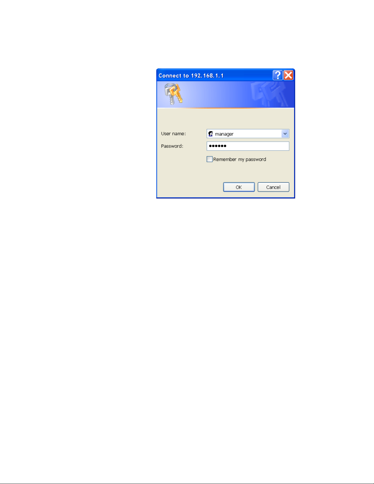
The AT-S101 Management Software displays the login dialog box,
shown in Figure 2.
Figure 2. AT-S101 Login Dialog Box
3. Enter the AT-S101 management login user name and password. The
default user name is “manager” and the default password is “friend.”
Then press OK. The login name and password are case-sensitive.
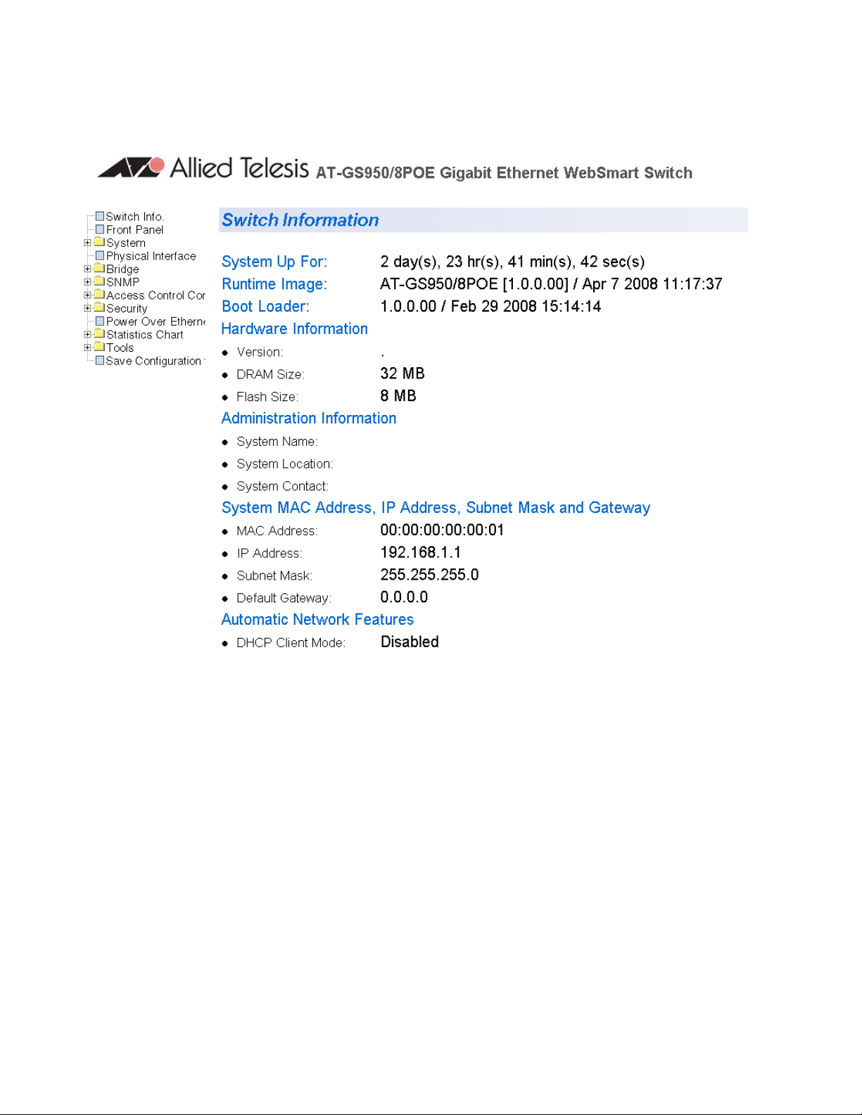
The Switch Information Page is displayed. See Figure 3 on page 16.
15
Page 16
Chapter 1: Starting a Web Browser Management Session
To change the user name and password, refer to “Configuring System
Management Information” on page 29.
16
Figure 3. Switch Information Page
The main menu is on the left side of the home page. It consists of the
following folders and web pages:
Switch Info.
Front Panel
System
Physical Interface
Bridge
SNMP
Access Control Config.
Security
Power Over Ethernet
Statistics Chart
Page 17
AT-S101 Management Software User’s Guide
Tools
Save Configuration
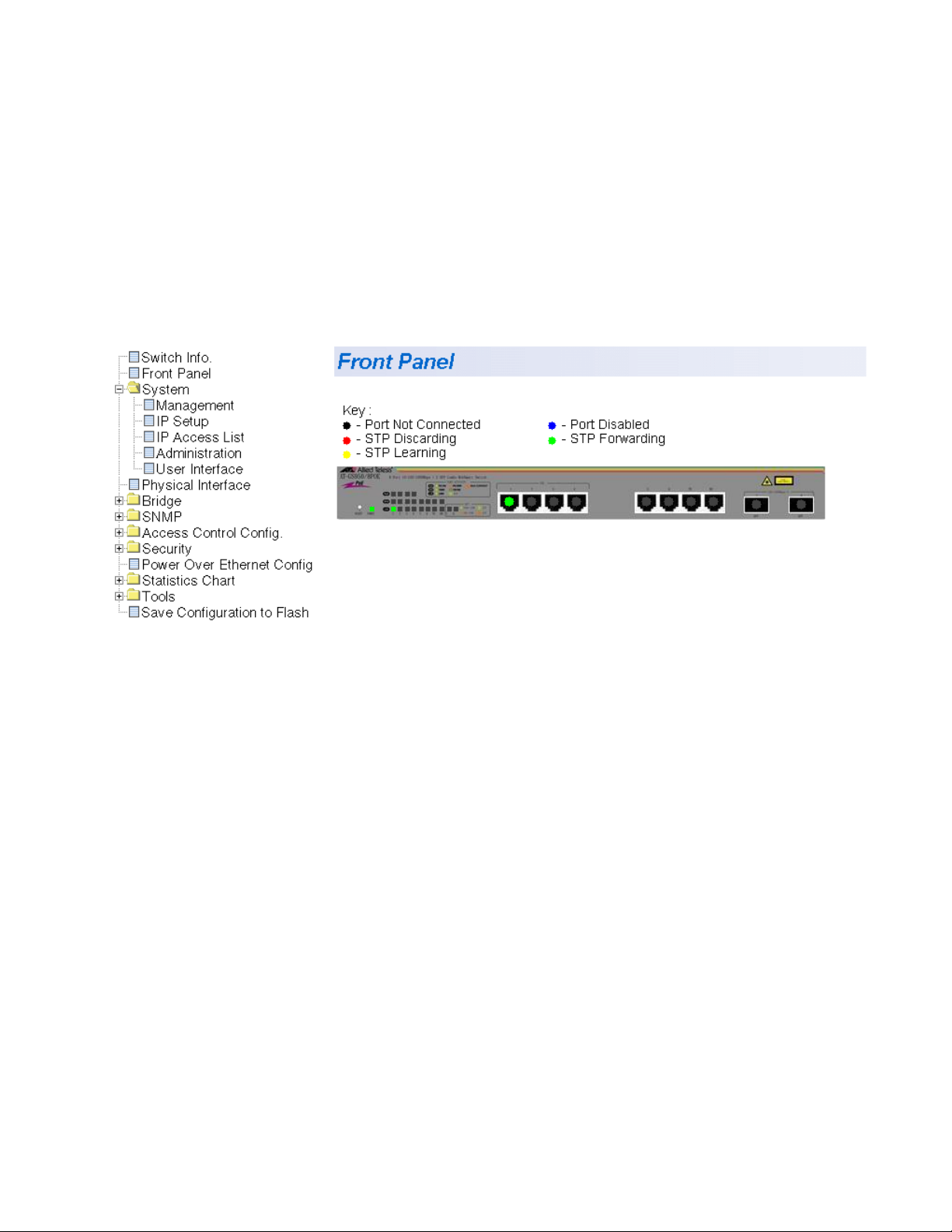
4. To see the front panel of the switch, select Front Panel from the menu
on the left side of the page.
The AT-S101 Management Software displays the front of the switch.
The window contains an image of the front of the switch. Ports that
have a link to an end node are green. Ports without a link are grey. An
example of a front panel is shown in Figure 4.
Figure 4. Front Panel Page
A web browser management session remains active even if you link to
other sites. You can return to the management web pages anytime as long
as you do not quit the browser.
17
Page 18

Chapter 1: Starting a Web Browser Management Session
Web Browser Tools
You can use the web browser tools to move around the management
pages. Selecting Back on your browser’s toolbar returns you to the
previous display. You can also use the browser’s bookmark feature to
save the link to the switch.
18
Page 19

Quitting a Web Browser Management Session
To exit a web browser management session, close the web browser.
AT-S101 Management Software User’s Guide
19
Page 20

Chapter 1: Starting a Web Browser Management Session
20
Page 21

Chapter 2
Basic Switch Parameters
This chapter provides procedures to perform basic switch activities such
as reassigning the IP address, enabling the DHCP Client, configuring new
usernames and passwords, and rebooting the system.
This chapter contains the following sections:
“Configuring an IP Address, Subnet Mask and Gateway Address” on
page 22
“Setting Up the IP Access List” on page 24
“Enabling and Disabling the DHCP Client” on page 27
“Configuring System Management Information” on page 29
“Configuring System Administration Information” on page 31
“Setting the User Interface Configuration” on page 34
“Viewing System Information” on page 36
“Rebooting a Switch” on page 39
“Pinging a Remote System” on page 41
“Returning the AT-S101 Management Software to the Factory Default
Values” on page 44
Note
To save your changes, select Save Configuration to Flash from
the menu on the left side of the page.
21
Page 22
Chapter 2: Basic Switch Parameters
Configuring an IP Address, Subnet Mask and Gateway Address
This procedure explains how to change the IP address, subnet mask, and
gateway address to the switch. Before performing the procedure, note the
following:
A gateway address is only required if you want to remotely manage
the device from a management station that is separated from the
switch by a router.
To configure the switch to automatically obtain its IP configuration from
a DHCP server on your network, go to “Enabling and Disabling the
DHCP Client” on page 27.
To change the switch’s IP configuration, perform the following procedure:
1. From the menu on the left side of the page, click the System folder.
The System folder expands.
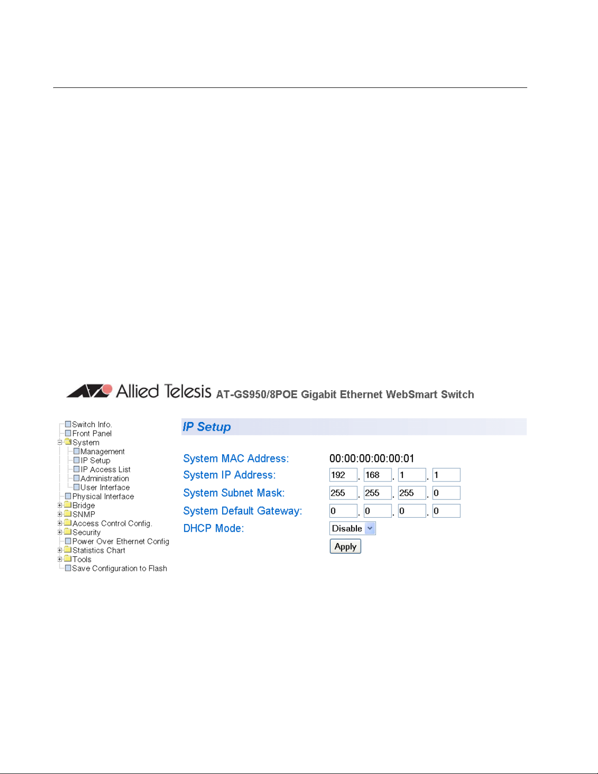
2. From the System folder, select IP Setup.
The IP Setup Page is shown in Figure 5.
22
Figure 5. IP Setup Page
Page 23

AT-S101 Management Software User’s Guide
3. Change the IP configuration parameters by entering new information in
the following fields:
System MAC Address
This parameter displays the MAC address of the switch. You cannot
change this parameter.
System IP Address
Displays the current IP address of the switch. To change the IP
address, enter a new IP address.
System Subnet Mask
Displays the current subnet mask of the switch. To change the subnet
mask, enter a new subnet mask.
System Default Gateway
Displays the default gateway of the switch. To change the default
gateway, enter a new gateway.
DHCP Mode
For information about setting this parameter, refer to “Enabling and
Disabling the DHCP Client” on page 27.
4. Click Apply.
Note
Changing the IP address ends your management session. To
resume managing the device, enter the new IP address of the switch
in the web browser’s URL field, as shown in Figure 1 on page 14.
5. After you log on to the switch with the new IP address, select Save
Configuration to Flash to save the new IP address to memory.
Caution
If you do not select Save Configuration to Flash, the IP address
may revert to its default setting when you power cycle the switch.
23
Page 24
Chapter 2: Basic Switch Parameters
Setting Up the IP Access List
The IP Access List feature, when enabled, restricts remote access to
management software by means of a user-configured list of IP addresses.
It does not restrict the management ping response activity, only web
access to the management software.
Note
By default, the IP Access List feature is disabled.
The procedures in this section describe how to enable or disable the IP
Access List feature and how to add or remove IP addresses from the list.
See the following sections:
“Creating an IP Access List” on page 24
“Deleting an IP Address” on page 26
Creating an IP
Access List
Note
You cannot modify an existing IP address.
To create a list of restricted IP addresses, perform the following
procedure:
1. From the menu on the left side of the page, click the System folder.
The System folder expands.
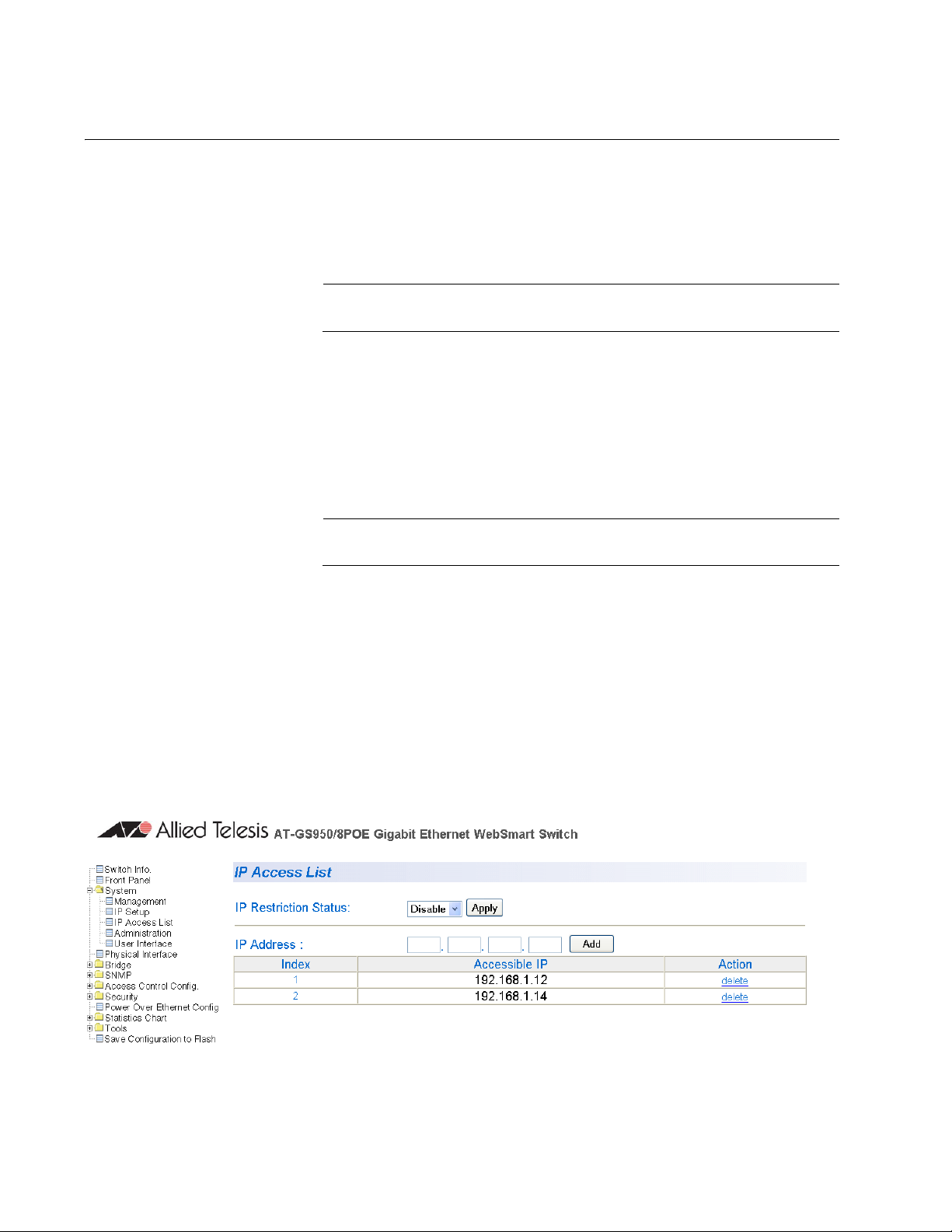
2. From the System folder, select IP Access List.
The IP Access List Page is shown in Figure 6.
24
Figure 6. IP Access List Page
Page 25

AT-S101 Management Software User’s Guide
3. To set the IP restriction status, select Disable or Enable in the pulldown menu next to the IP Restriction Status field. Then click Apply.
By default, the IP Restriction Status field is set to Disable.
4. Enter an IP address that you want to prevent from accessing the
switch in the xxx.xxx.xxx.xxxx format next to the IP Address field.
Then click Add.
The IP address is added to the IP Access List Table.
5. From the menu on the left side of the page, select Save Configuration
to Flash to save your changes.
25
Page 26

Chapter 2: Basic Switch Parameters
Deleting an IP
Address
To delete an IP address from the IP Access List, perform the following
procedure:
1. From the menu on the left side of the page, click the System folder.
The System folder expands.
2. From the System folder, select IP Access List.
The IP Access List Page is displayed. See Figure 6 on page 24.
3. Select delete
The IP address is removed from the IP Access List Table.
4. From the menu on the left side of the page, select Save
Configuration to Flash to save your changes.
next to the IP address that you want to remove.
26
Page 27

Enabling and Disabling the DHCP Client
Since the AT-GS950/8POE switch is a web-only switch and does not have
a local console connection, you must be careful when you change the
IP address of the switch by enabling the DHCP client. To look up the IP
address on a DHCP server, you must have the MAC address of the ATGS950/8POE switch. Once the switch obtains a new IP address from the
DHCP server, the switch becomes inaccessible and the MAC address can
no longer be viewed in the AT-S101 software.
Before you enable the DHCP client, record the switch’s MAC address. You
can view the MAC address on the System Information Page when you first
log onto the switch. See “Viewing System Information” on page 36. Or, you
can see the MAC address on the label affixed to the switch.
If the switch power cycles before you save the new configuration, the
software reverts to the default IP address value. Or, if you press the Reset
button before you save the DHCP client on the switch, the software reverts
the default IP address value. In either case, the IP address value is
192.168.1.1.
AT-S101 Management Software User’s Guide
This procedure explains how to activate and deactivate the DHCP client
on the switch. When the client is activated, the switch obtains its IP
configuration, its IP address and subnet mask, from a DHCP server on
your network. Before performing the procedure, note the following:
By default, the DHCP client is disabled on the switch.
The DHCP client does not support BOOTP.
After you enable DHCP, you will end the current management session.
Log on with the new IP address (provided by your system
administrator) using the procedure described in “Establishing a
Remote Connection to the Web Browser Interface” on page 14.
Caution
Record the MAC address of your switch before you begin this
procedure.
To activate or deactivate the DHCP client on the switch, perform the
following procedure:
1. From the menu on the left side of the page, click the System folder.
The System folder expands.
2. From the System folder, select IP Setup.
The IP Setup Page is shown in Figure 5 on page 22.
27
Page 28

Chapter 2: Basic Switch Parameters
3. From the pull-down menu next to the DHCP Mode field, select Enable
or Disable.
By default, this field is set to Disable.
4. Click Apply.
If you enable the DHCP client, the web server connection to the switch
is lost.
If you disable the DHCP client, note the new System IP Address
value that you assigned to the switch. Record this value for future use.
Caution
Enabling or disabling DHCP ends your management session.
Caution
If you do not select Save Configuration to Flash, the DHCP mode
reverts to its default setting of 192.168.1.1 when you power cycle
the switch.
5. Log on to the switch with the new IP address and immediately save
your configuration by selecting Save Configuration to Flash from the
menu on the left side of the page.
If you enable DHCP and then save your configuration, you save the IP
address on the DHCP server.
If you disable DHCP, enter a new IP address, and then save your
configuration, you have saved the DHCP setting and the new IP
address on the switch.
28
Page 29
Configuring System Management Information
This section explains how to assign a name to the switch, as well as the
location of the switch and the name of the switch’s administrator. Entering
this information is optional.
To set a switch’s administration information, perform the following
procedure:
1. From the menu on the left side of the page, click the System folder.
The System folder expands.
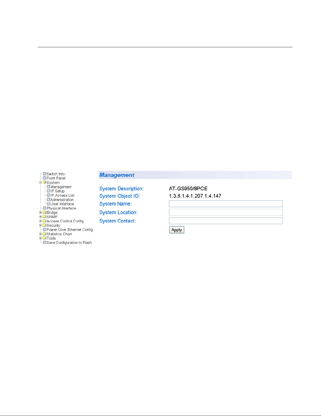
2. From the System folder, select Management.
The Management Page is shown in Figure 7.
AT-S101 Management Software User’s Guide
Figure 7. Management Page
3. Configure the following parameters as necessary:
System Description
Specifies the model number of the switch. You cannot change this
parameter.
System Object ID
Indicates the unique SNMP MIB object that identifies the AT-GS950/
8POE switch model. You cannot change this parameter.
System Name
Specifies a name for the switch, for example, Sales. The name is
optional and may contain up to 50 characters.
29
Page 30

Chapter 2: Basic Switch Parameters
Note
Allied Telesis recommends that you assign a name to the switch. A
name can help you identify the switch when you manage it and can
also help you avoid performing a configuration procedure on the
wrong switch.
System Location
Specifies the location of the switch. The location is optional and may
contain up to 50 characters.
System Contact
Specifies the name of the network administrator responsible for
managing the switch. This contact name is optional and may contain
up to 50 characters.
4. Click Apply.
5. From the menu on the left side of the page, select Save
Configuration to Flash to save your changes.
30
Page 31

Configuring System Administration Information
This section explains how to enable password protection and create users
in the web interface. See the following sections:
“Adding System Administration Information” on page 31
“Modifying Administration Information” on page 32
“Deleting Administration Information” on page 33
AT-S101 Management Software User’s Guide
Adding System
Administration
Information
To set a switch’s administration information, perform the following
procedure:
1. From the menu on the left side of the page, click the System folder.
The System folder expands.
2. From the System folder, select Administration.
The Administration Page is shown in Figure 8.
Figure 8. Administration Page
3. To enable or disable password protection, select Enable or Disable
from the pull-down menu next to the Password Protection field. Then
click Apply.
You can control login authentication by enabling password protection
which requires a user to supply a password when logging onto the
switch. If you disable password protection, a user can login without
inputting a password. By default, this field is set to Enable.
31
Page 32

Chapter 2: Basic Switch Parameters
4. To create an entry number, type 1 through 8 in the box next to the
Entry number field.
This value appears as the Index value in the Administration table at the
bottom of the page.
5. To create a user name, enter a user name in the box next to the User
Name field.
You can enter a value of up to 12 alphanumeric characters.
6. To add a password for the above user name, enter a password of up
to 12 alphanumeric characters in the box next to the Password field.
7. To confirm the above password, retype the password in the box next
to the Confirm Password field.
8. Click Add to activate your changes on the switch.
9. From the menu on the left side of the page, select Save
Configuration to Flash to save your changes.
Modifying
Administration
Information
To modify the a user name password, perform the following procedure.
1. From the menu on the left side of the page, click the System folder.
The System folder expands.
2. From the System folder, select Administration.
The Administration Page is shown in Figure 8 on page 31.
3. Select the user name that you want to change and click modify
.
32
Page 33

AT-S101 Management Software User’s Guide
The Modify Administration Page is displayed. See Figure 9.
Deleting
Administration
Information
Figure 9. Modify Administration Page
4. To change a password, enter a password of up to 12 alphanumeric
characters in the box next to the Password field.
5. To confirm the above password, retype the password in the box next to
the Confirm Password field.
6. Click Apply to activate your changes on the switch.
7. From the menu on the left side of the page, select Save Configuration
to Flash to save your changes.
To delete a user name, perform the following procedure.
1. From the menu on the left side of the page, click the System folder.
The System folder expands.
2. From the System folder, select Administration.
The Administration Page is shown in Figure 8 on page 31.
3. Select the user name that you want to delete and click delete
.
The user name is removed from the Administration Table.
4. Click Add to activate your changes on the switch.
33
Page 34

Chapter 2: Basic Switch Parameters
Setting the User Interface Configuration
This procedure explains how to adjust the user interface and security
features on the switch. With this procedure you can:
Enable an SNMP Agent. To configure the SNMP feature, see Chapter
8, “Simple Network Management Protocol (SNMP)” on page 99.
Enable and disable the web server.
To set the switch’s user interface configuration, perform the following
procedure:
1. From the menu on the left side of the page, click the System folder.
The System folder expands.
2. From the System folder, select User Interface.
The User Interface Page is shown in Figure 10.
34
Figure 10. User Interface Page
3. To enable or disable an SNMP agent, do the following:
a. Click the SNMP Agent parameter and choose Enable or Disable
from the list. The default is Enable. When you enable this
parameter, the SNMP agent is enabled.
b. Click Apply.
Page 35

AT-S101 Management Software User’s Guide
4. To enable or disable the web server, do the following:
a. Click the Web Server parameter and choose Enable or Disable
from the pull-down menu. The default is Enable. When you enable
this parameter, you can use a web browser to manage the switch
remotely.
Note
Disabling the web browser automatically ends your remote
management session. If this occurs, press the Reset button to
recycle the power to the switch. Then logon to the switch.
b. Click Apply.
5. From the menu on the left side of the page, select Save Configuration
to Flash to save your changes.
35
Page 36

Chapter 2: Basic Switch Parameters
Viewing System Information
To view general information about the switch, perform the following
procedure:
1. From the menu on the left side of the page, click the System folder.
The System folder expands.
2. Select Switch Info.
The Switch Information Page is shown in Figure 11.
36
Figure 11. Switch Information Page
Page 37

AT-S101 Management Software User’s Guide
The Switch Information Page displays the following information:
System Up For
The number of days, hours, and minutes that the switch has been
running since it was last rebooted.
Runtime Image
The version number and build date of the runtime firmware.
Boot Loader
The version number and build date of the bootloader firmware.
Hardware Information Section:
Version
The hardware version number.
DRAM Size
The size of the DRAM, in megabytes.
Flash Size
The size of the flash memory, in megabytes.
Administration Information Section:
Switch Name
The name assigned to the switch. To give the switch a name, refer to
“Configuring System Management Information” on page 29.
Switch Location
The location of the switch. To specify the location, refer to “Configuring
System Management Information” on page 29.
Switch Contact
The contact person responsible for managing the switch. To specify
the name of a contact, refer to “Configuring System Management
Information” on page 29.
System MAC Address, IP Address, Subnet Mask, and Gateway
Section:
MAC Address
The MAC address of the switch. You cannot change this value.
IP Address
The IP address of the switch. Refer to “Configuring an IP Address,
Subnet Mask and Gateway Address” on page 22 to manually assign
an IP address or “Enabling and Disabling the DHCP Client” on page 27
to activate the DHCP client.
Subnet Mask
The subnet mask for the switch. Refer to “Configuring an IP Address,
Subnet Mask and Gateway Address” on page 22 to manually assign a
37
Page 38

Chapter 2: Basic Switch Parameters
subnet mask or “Enabling and Disabling the DHCP Client” on page 27
to activate the DHCP client.
Default Gateway
Default gateway’s IP address. Refer to “Configuring an IP Address,
Subnet Mask and Gateway Address” on page 22 to manually assign a
gateway address or “Enabling and Disabling the DHCP Client” on
page 27 to activate the DHCP client.
Automatic Network Features Section:
DHCP Mode
The status of the DHCP client on the switch. For information about
setting this parameter, refer to “Enabling and Disabling the DHCP
Client” on page 27.
38
Page 39

Rebooting a Switch
AT-S101 Management Software User’s Guide
This procedure reboots the switch and reloads the AT-S101 Management
Software from flash memory. You may want to reboot the device if you
believe it is experiencing a problem.
Caution
The switch does not forward network traffic during the reboot
process. Some network traffic may be lost.
To reboot a switch, perform the following procedure:
1. From the menu on the left side of the page, select the Tools folder.
The Tools folder expands.
2. From the Tools folder, select Reboot.
The Reboot Page is shown in Figure 12.
Figure 12. Reboot Page
3. For the Reboot Type, select Normal from the pull-down menu. This is
the default setting.
39
Page 40

Chapter 2: Basic Switch Parameters
Note
Two additional Reboot Type options, Factory Default and Reset to
Factory Default Except IP Address, are described in “Returning
the AT-S101 Management Software to the Factory Default Values”
on page 44.
4. For the Reboot Status, use the pull-down menu to select Start to
begin the reboot.
5. Click Apply.
The switch immediately begins to reload the AT-S101 Management
Software. This process takes approximately one minute to complete.
You can not manage the device during the reboot. After the reboot is
finished, you can log in again if you want to continue to manage the
device.
40
Page 41

Pinging a Remote System
This procedure instructs the switch to ping a node on your network. This
procedure is useful in determining whether an active link exists between
the switch and another network device. Note the following before
performing the procedure:
The device you are pinging must be a member of the Default VLAN. In
other words, the port on the switch through which the node is
communicating with the switch must be an untagged or tagged
member of the Default VLAN.
To ping a network device, perform the following procedure:
1. From the menu on the left side of the page, select the Tools folder.
The Tools folder expands.
2. From the Tools folder, select Ping.
AT-S101 Management Software User’s Guide
The Ping Test Configuration Page is displayed. See Figure 13 on page
41.
Figure 13. Ping Test Configuration Page
3. Configure the following parameters:
Destination IP Address
The IP address of the node you want to ping.
41
Page 42

Chapter 2: Basic Switch Parameters
Timeout Value
Specifies the length of time, in seconds, the switch waits for a
response before assuming that a ping has failed. The default is 3
seconds.
Number of Ping Requests
Specifies the number of ping requests you want the switch to perform.
The default is 10.
4. Click Start.
5. To view the ping results, click Show Ping Results.
A sample Ping Test Results Page is displayed. See Figure 14.
42
Figure 14. Ping Test Results Page
The following information is provided:
Destination IP Address
Indicates the IP address of the unit that receives the ping.
Pass
Indicates the percentage of times the ping passed.
Page 43

AT-S101 Management Software User’s Guide
Average Time
Indicates the time, in milliseconds, the ping was received.
6. Click Back to Ping Test to return to the Ping Test Configuration Page.
7. From the menu on the left side of the page, select Save Configuration
to Flash to save your changes.
43
Page 44

Chapter 2: Basic Switch Parameters
Returning the AT-S101 Management Software to the Factory Default Values
This procedure returns all AT-S101 Management Software parameters to
their default values and deletes all tagged and port-based VLANs on the
switch. The AT-S101 Management Software default values are listed in
Appendix A, “AT-S101 Management Software Default Settings” on page
231.
Caution
This procedure causes the switch to reboot. The switch does not
forward network traffic during the reboot process. Some network
traffic may be lost.
To return the AT-S101 software to the default settings, perform the
following procedure:
1. From the Tools folder, select Reboot.
The Reboot Page is shown in Figure 12 on page 39.
2. For the Reboot Type field, use the pull-down menu to select one of
the following:
Factory Default
Resets all switch parameters to the factory default settings, including
the IP address, subnet mask, and gateway address.
Factory Default Except IP Address
Resets all switch parameters to the factory default settings, but retains
the IP address, subnet mask, and gateway settings. If the DHCP client
is enabled, it remains enabled after this reset.
3. For the Reboot Status field, use the pull-down menu to select Start to
begin the reboot.
4. Click Apply.
The switch is rebooted. You must wait for the switch to complete the
reboot process before reestablishing your management session.
44
Page 45

Chapter 3
Virtual LANs
This chapter contains a description of Virtual Local Area Networks
(VLANs) and procedures for creating, modifying, and deleting port-based
and tagged VLANs from a web browser management session. This
chapter contains the following sections:
“VLAN Overview” on page 46
“Displaying Ports and Assigning Ports to a VLAN” on page 50
“Creating a Tagged VLAN” on page 51
“Modifying a Tagged VLAN” on page 53
“Deleting a Tagged VLAN” on page 55
“Creating a Port-Based VLAN” on page 56
“Modifying a Port-Based VLAN” on page 57
“Deleting a Port-Based VLAN” on page 59
Note
To save your changes, select Save Configuration to Flash from
the menu on the left side of the page.
45
Page 46

Chapter 3: Virtual LANs
VLAN Overview
A VLAN is a group of ports on an Ethernet switch that form a logical
Ethernet segment. The ports of a VLAN form an independent traffic
domain where the traffic generated by the nodes of a VLAN remains within
the VLAN.
With VLANs, you can segment your network through the switch’s AT-S101
Management Software and group nodes with related functions into their
own separate, logical LAN segments. These VLAN groupings can be
based on similar data needs or security requirements. For example, you
can create separate VLANs for each department in your company, such
as one for Sales and another for Accounting.
VLANs offer several important benefits:
Improved network performance
Network performance often suffers as networks grow in size and as
data traffic increases. The more nodes on each LAN segment vying for
bandwidth, the greater the likelihood overall network performance
decreases.
VLANs improve network perform because traffic stays within the
separate, logical LAN segment of the VLAN. The nodes of a VLAN
receive traffic only from nodes of the same VLAN. This reduces the
need for nodes to handle traffic that is not destined for them. It also
frees up bandwidth within all the logical workgroups.
In addition, because each VLAN constitutes a separate broadcast
domain, broadcast traffic remains within the VLAN. This too can
improve overall network performance.
Increased security
Because data traffic generated by a node in a VLAN is restricted only
to the other nodes of the same VLAN, you can use VLANs to control
the flow of packets in your network and prevent packets from flowing to
unauthorized end nodes.
Simplified network management
In addition, VLANs can simplify network management. Before the
advent of VLANs, physical changes to the network often had to been
made at the switches in the wiring closets. For example, if an
employee changed departments, changing the employee’s LAN
segment assignment might require a change to the cabling of the
switches.
46
With VLANS, you can change the LAN segment assignment of an end
node connected to the switch through the AT-S101 software. Also, you
Page 47

AT-S101 Management Software User’s Guide
can change the VLAN memberships through the management
software without moving the workstations physically or change group
memberships without moving cables from one port to another.
In addition, a virtual LAN can span more than one switch. This means
that the end nodes of a VLAN do not need to be connected to the
same switch and so are not restricted to being in the same physical
location.
The AT-GS950/8POE switch supports the following types of VLANs:
Port-based VLANs
Tagged VLANs
Both types of VLANs are described in the following sections.
Port-based
VLAN Overview
As explained in the “VLAN Overview” on page 46, a VLAN consists of a
group of ports on an Ethernet switch that form an independent traffic
domain. Traffic generated by the end nodes of a VLAN remains within the
VLAN and does not cross over to the end nodes of other VLANs unless
there is an interconnection device, such as a router or Layer 3 switch.
A port-based VLAN is a group of ports on an AT-GS950/8POE switch that
form a logical Ethernet segment. A port-based VLAN can have as many or
as few ports as needed. The VLAN can consist of all the ports on an
Ethernet switch, or just a few ports.
The parts of a port-based VLAN in the AT-S101 Management Software
are:
VLAN name
Group ID
VLAN Name
To create a port-based VLAN, you must give it a name that reflects the
function of the network devices that are VLAN members, such as Sales,
Production, and Engineering.
Group ID
Each VLAN in a network must have a unique number assigned to it. This
number is called the Group ID. This number uniquely identifies a VLAN in
the switch.
47
Page 48

Chapter 3: Virtual LANs
Each port of a port-based VLAN can belong to as many VLANs as
needed. Therefore, traffic can be forwarded to the members of the groups
which the port is assigned to. For example, port 1 and port 2 are members
of group 1 and ports 1 and 3 are members of group 2. In this case, traffic
from port 1 is forwarded to ports 2 and 3, traffic from port 2 is forwarded
only to port 1, and traffic from port 3 is forwarded only to port 1.
General Rules for Creating a Port-based VLAN
Below is a summary of the general rules to observe when creating a portbased VLAN.
Assign a name to each port-based VLAN.
Assign each port-based VLAN a Group ID.
The AT-GS950/8POE switch can support up to 52 port-based VLANs.
Tagged VLAN
Overview
The second type of VLAN supported by the AT-S101 Management
Software is the tagged VLAN. In this type of VLAN, membership is
determined by information within the frames that are received on a port
and the VLAN configuration of each port.
The VLAN information within an Ethernet frame is referred to as a tag or
tagged header. A tag, which follows the source and destination addresses
in a frame, contains the Group ID of the VLAN to which the frame belongs
(IEEE 802.3ac standard). This number uniquely identifies each VLAN in a
network.
When a switch receives a frame with a VLAN tag, referred to as a tagged
frame, the switch forwards the frame only to those ports whose Group ID
equals the VLAN tag.
A port that receives or transmits tagged frames is referred to as a tagged
port. Any network device connected to a tagged port must be IEEE
802.1Q-compliant. This is the standard that outlines the requirements and
standards for tagging. The device must be able to process the tagged
information on received frames and add tagged information to transmitted
frames.
A tagged VLAN consists of the following:
48
VLAN Name
Group ID
Tagged and Untagged Ports
Port VLAN identifier (PVID)
Page 49

AT-S101 Management Software User’s Guide
Tagged and Untagged Ports
When you specify that a port is a member of a tagged VLAN, you need to
specify that it is tagged or untagged. You can have a combination of
tagged and untagged ports in the same VLAN.
Packet transmission from a tagged port differs from packet transmission
from an untagged port. When a packet is transmitted from a tagged port,
the tagged information within the packet is maintained when it is
transmitted to the next network device. If the packet is transmitted from an
untagged port, the VLAN tag information is removed from the packet
before it is transmitted to the next network device.
The IEEE 802.1Q standard describes how tagging information within a
packet is used to forward or discard traffic throughout the switch. If the
incoming packet has a VLAN tag that matches one of the Group IDs of
which the port is a member, the packet is accepted and forwarded to the
appropriate port(s) within that VLAN. If the incoming packet’s VLAN tag
does not match one of the Group IDs assigned to the port, the packet is
discarded.
Port VLAN Identifier
When an untagged packet is received on a port in a tagged VLAN, it is
assigned to one of the VLANs of which that port is a member. The
deciding factor in this process is the Port VLAN Identifier (PVID). Both
tagged and untagged ports in a tagged VLAN must have a PVID assigned
to them. The default value of the PVID for each port is 1. The switch
associates a received untagged packet to the Group ID that matches the
PVID assigned to the port. As a result, the packet is only forwarded to
those ports that are members of that VLAN.
General Rules for Creating a Tagged VLAN
Below is a summary of the rules to observe when you create a tagged
VLAN.
Each tagged VLAN must be assigned a unique VID. If a particular
VLAN spans multiple switches, each part of the VLAN on the different
switches must be assigned the same VID.
A tagged port can be a member of multiple VLANs.
The AT-GS950/8POE switch can support up to 200 tagged VLANS.
49
Page 50

Chapter 3: Virtual LANs
Displaying Ports and Assigning Ports to a VLAN
By default, all of the ports on the switch are assigned to the Tagged VLAN.
The procedure described in this section allows you to display the current
VLAN assignment of ports. In addition, it permits you to assign ports to
tagged or a port-based VLAN. However, you can assign ports to a portbased VLAN only after you have created a port-based VLAN with the
procedure described in “Creating a Port-Based VLAN” on page 56.
To assign ports to a tagged or port-based VLAN, perform the following
procedure:
1. From the menu on the left side of the page, select Bridge.
The Bridge folder expands.
2. From the Bridge folder, select VLAN.
The VLAN folder expands.
3. From the VLAN folder, select VLAN Mode.
The VLAN Mode Page is shown in Figure 15.
Figure 15. VLAN Mode Page
4. To add ports to a Tagged or Port-Based VLAN, select the ports and
then click Apply.
50
Page 51

Creating a Tagged VLAN
To create a tagged VLAN, perform the following procedure:
1. From the menu on the left side of the page, select Bridge.
The Bridge folder expands.
2. From the Bridge folder, select VLAN.
The VLAN folder expands.
3. From the VLAN folder, select Tagged VLAN.
The Tagged VLAN Page is shown in Figure 16
AT-S101 Management Software User’s Guide
Figure 16. Tagged VLAN Page
4. To assign a VLAN ID, type in a VLAN ID in the VLAN ID field.
Choose a value between 2 and 4,000. You can configure up to 200
tagged VLANs.
5. To assign a name to the VLAN, type in a name in the VLAN Name
field.
Enter a value of up to 32 characters.
6. To assign ports to the VLAN, click on the port numbers labeled either
Static Tagged or Static Untagged. Then click Apply.
By default, all the ports are assigned to the Not Member category.
51
Page 52

Chapter 3: Virtual LANs
For an example of Tagged VLANs, see Figure 17.
Figure 17. Example of Tagged VLAN Page
7. From the menu on the left side of the page, select Save
Configuration to Flash to save your changes.
52
Page 53

Modifying a Tagged VLAN
To modify the name or port assignments of a tagged VLAN, perform the
following procedure:
1. From the menu on the left side of the page, select Bridge.
The Bridge folder expands.
2. From the Bridge folder, select VLAN.
The VLAN folder expands.
3. From the VLAN folder, select Tagged VLAN.
An Example of a Tagged VLAN page is shown in Figure 17 on page
52.
AT-S101 Management Software User’s Guide
4. In the VLAN Action column, click modify
want to change.
The Modify VLAN Page is displayed, see Figure 18
Figure 18. Modify VLAN Page
next to the VLAN that you
5. To change the VLAN ID, type in a VLAN ID in the VLAN ID field.
You can choose a value between 2 and 4,000. You can configure up to
52 VLANs.
53
Page 54

Chapter 3: Virtual LANs
6. To change the name of the VLAN, type in a name in the VLAN Name
field.
7. To assign ports to the VLAN, click on the port numbers labeled either
Static Tagged or Static Untagged. Then click Apply.
8. From the menu on the left side of the page, select Save
Configuration to Flash to save your changes.
54
Page 55

Deleting a Tagged VLAN
To delete a tagged VLAN, perform the following procedure:
1. From the menu on the left side of the page, select Bridge.
The Bridge folder expands.
2. From the Bridge folder, select VLAN.
The VLAN folder expands.
3. From the VLAN folder, select Tagged VLAN.
An example of the Tagged VLAN Page is shown in Figure 17 on page
52.
AT-S101 Management Software User’s Guide
4. In the VLAN Action column, click delete
want to delete.
A confirmation prompt is displayed.
5. Click OK to delete the VLAN or Cancel to cancel the deletion.
Note
You cannot delete the Default VLAN which has a VID of 1.
6. From the menu on the left side of the page, select Save Configuration
to Flash to save your changes.
next to the VLAN that you
55
Page 56

Chapter 3: Virtual LANs
Creating a Port-Based VLAN
To create a port-based VLAN, perform the following procedure:
1. From the menu on the left side of the page, select Bridge.
The Bridge folder expands.
2. From the Bridge folder, select VLAN.
The VLAN folder expands.
3. From the VLAN folder, select Port-Based VLAN.
The Port-Based VLAN Page is shown in Figure 19.
56
Figure 19. Port-Based VLAN Page
4. To assign a VLAN ID, type a VLAN ID in the VLAN ID field.
Choose a value between 1 and 52.
5. To assign a name to a VLAN, type in a name in the VLAN Name field.
Enter a value of up to 32 characters.
6. To assign ports to the VLAN, click on the port numbers labeled Group
Member. Then click Apply.
7. From the menu on the left side of the page, select Save
Configuration to Flash to save your changes.
Page 57

Modifying a Port-Based VLAN
To modify the name or port assignments of a port-based VLAN, perform
the following procedure:
1. From the menu on the left side of the page, select Bridge.
The Bridge folder expands.
2. From the Bridge folder, select VLAN.
The VLAN folder expands.
3. From the VLAN folder, select Port-Based VLAN.
The Port-Based VLAN Page is shown in Figure 19 on page 56.
AT-S101 Management Software User’s Guide
4. In the VLAN Action column, click modify
want to change.
The Modify Port-based VLAN Page is shown in Figure 20.
Figure 20. Modify Port-based VLAN
next to the VLAN that you
5. To change the name of the VLAN, type in a name in the VLAN Name
field.
Enter a value of up to 32 characters.
6. To assign ports to the VLAN, click on the port numbers labeled either
Group Member or Not Member. Then click Apply.
57
Page 58

Chapter 3: Virtual LANs
7. From the menu on the left side of the page, select Save
Configuration to Flash to save your changes.
58
Page 59

Deleting a Port-Based VLAN
To delete a port-based VLAN, perform the following procedure:
1. From the menu on the left side of the page, select Bridge.
The Bridge folder expands.
2. From the Bridge folder, select VLAN.
The VLAN folder expands.
3. From the VLAN folder, select Port-Based VLAN.
The Port-Based VLAN Page is shown in Figure 19 on page 56.
AT-S101 Management Software User’s Guide
4. In the VLAN Action column, click delete
want to delete.
A confirmation prompt is displayed.
5. Click OK to delete the VLAN or Cancel to cancel the deletion.
Note
You cannot delete the Default VLAN which has a VID of 1.
6. From the menu on the left side of the page, select Save Configuration
to Flash to save your changes.
next to the VLAN that you
59
Page 60

Chapter 3: Virtual LANs
60
Page 61

Chapter 4
Quality of Service (QoS)
This chapter contains a description of the QoS feature and the procedures
for configuring Quality of Service (QoS). This chapter includes the
following sections:
“Overview” on page 62
“Mapping CoS Priorities to Egress Queues” on page 65
“Configuring CoS” on page 67
Note
To save your changes, select Save Configuration to Flash from
the menu on the left side of the page.
61
Page 62

Chapter 4: Quality of Service (QoS)
Overview
When a port on an Ethernet switch becomes oversubscribed—its egress
queues contain more packets than the port can handle in a timely
manner—the port may be forced to delay the transmission of some
packets, which delays packets from reaching their destinations. A port
may be forced to delay transmission of packets while it handles other
traffic, and, in some situations, some packets destined to be forwarded to
an oversubscribed port from other switch ports may be discarded.
Minor delays are often inconsequential to a switch or its performance. But
there are applications, referred to as delay or time sensitive applications,
that can be impacted by packet delays. Voice transmission and video
conferencing are two examples. If packets carrying data for either of these
are delayed from reaching their destination, the audio or video quality may
suffer.
This is where the QoS feature can be of value. It allows you to manage the
flow of traffic through a switch by having the switch ports give higher
priority to some packets, such as delay sensitive traffic, over other
packets. This is referred to as prioritizing traffic.
The QoS feature actually consists of several different elements. The
element supported by the AT-GS950/8POE switch is called Class of
Service (CoS) and which applies primarily to tagged packets and DSCP
which priorities IP packets. As explained in “Tagged VLAN Overview” on
page 105, a tagged packet contains information that specifies the VLAN to
which the packet belongs.
A tagged packet can also contain a priority level. This priority level is used
by switches and other networking devices to determine how important
(delay sensitive) a packet is in comparison to other packets. Packets of a
high priority are typically handled before packets of a low priority.
CoS, as defined in the IEEE 802.1p standard, has eight levels of traffic
classes. In the AT-S101 software, the priorities are 0 to 7, with 0 the
lowest priority and 7 the highest priority.
When a tagged packet is received by a port, it is examined by the
AT-S101 software for its priority. The switch software uses the priority to
determine which egress priority queue the packet should be stored in on
the egress port.
Each port on the AT-GS950/8POE switch has four priority queues, 0 (low)
to 3 (high). When a tagged packet enters a switch port, the switch
responds by placing the packet into one of the queues according to the
assignments shown in Table 1 on page 63. A packet in a high priority
egress queue is typically transmitted from a port sooner than a packet in a
low priority queue.
62
Page 63

AT-S101 Management Software User’s Guide
Table 1. Default Mappings of IEEE 802.1p Priority Levels
to Egress Port Priority Queues
AT-GS950/8POE
IEEE 802.1p Traffic Class
Egress Port Priority
Queue
00
10
20
31
42
52
63
73
For example, a tagged packet with a priority tag of 6 is placed in the
egress port’s highest priority queue of 3, while a packet with a priority tag
of 1 is placed in the lowest priority queue.
Note
QoS is disabled by default on the switch.
You can customize these priority-to-queue assignments using the
AT-S101 Management Software. The procedure for changing the default
mappings is found in “Mapping CoS Priorities to Egress Queues” on
page 65. Note that because all ports must use the same priority-to-egress
queue mappings, these mappings are applied at the switch level. They
cannot be set on a per-port basis.
You can configure a port to ignore the priority levels in its tagged packets
and use a temporary priority level assigned to the port instead. For
instance, perhaps you decide that all tagged packets received by port 4
should be assigned a priority level of 5, regardless of the priority level in
the packets themselves. The procedure for overriding priority levels is
explained in “Configuring CoS” on page 67.
CoS relates primarily to tagged packets rather than untagged packets
because untagged packets do not contain a priority level. By default, all
untagged packets are placed in a port’s Q0 egress queue, the queue with
the lowest priority. But you can override this and instruct a port’s untagged
frames to be stored in a higher priority queue. The procedure for this is
also explained in “Configuring CoS” on page 67.
63
Page 64

Chapter 4: Quality of Service (QoS)
One last thing to note is that the CoS feature does not change the priority
level in a tagged packet. The packet leaves the switch with the same
priority it had when it entered. This is true even if you change the default
priority-to-egress queue mappings.
The default setting for the Quality of Service feature is disabled. When the
feature is disabled, all tagged packets are stored in the lowest priority
queue of a port.
64
Page 65

Mapping CoS Priorities to Egress Queues
This procedure explains how to change the default mappings of CoS
priorities to egress priority queues, as shown in Table 1 on page 63. This
is set at the switch level. You cannot set these mappings on a per-port
level. You can also use this procedure to enable and disable QoS on the
switch.
To change the default mappings of CoS priorities to egress priority queues
or to enable or disable the QoS feature, perform the following procedure:
1. From the menu on the left side of the page, select Bridge.
The Bridge folder expands to show the VLAN folder.
2. From the VLAN folder, select CoS.
The CoS Page is shown in Figure 21.
AT-S101 Management Software User’s Guide
Figure 21. CoS Page
3. To enable or disable QoS, select Enable or Disable from the QoS
Status pull-down menu. The default is Disable.
4. To change the egress priority queue assignment of an 802.1p priority
class, click the dialog circle of the queue for the corresponding priority.
65
Page 66

Chapter 4: Quality of Service (QoS)
For example, to direct all tagged traffic with a traffic class of 4 to
egress queue 3 on the ports, click the dialog circle for queue 3 in the
traffic class 4 row.
5. Click Apply.
Note
The switch does not alter the original priority level in tagged frames.
Frames leave the switch with the same priority level they had when
they entered the switch.
6. From the menu on the left side of the page, select Save
Configuration to Flash to save your changes.
66
Page 67

Configuring CoS
AT-S101 Management Software User’s Guide
As explained in “Overview” on page 62, a packet received by a port is
placed it into one of four priority queues on the egress port according to
the switch’s mapping of 802.1p priority levels to egress priority queues.
The default mappings are shown in Table 1 on page 63.
You can override the mappings at the port level by assigning a new default
egress queue to a port. Note that this assignment is made on the ingress
port before the frame is forwarded to the egress port. Consequently, you
need to configure this feature on the ingress port. For example, you can
configure a port so that all ingress frames are stored in egress queue 3 of
the egress port, regardless of the priority levels that might be in the frames
themselves, as found in tagged frames.
Note
The switch does not alter the original priority level of tagged frames.
Frames leave the switch with the same priority level they had when
they entered the switch.
To configure CoS for a port, perform the following procedure:
1. From the menu on the left side of the page, select Bridge.
The Bridge folder expands to show the VLAN folder.
2. From the VLAN folder, select Default Port VLAN.
The Default Port VLAN & CoS Page is shown in Figure 22.
Figure 22. Default Port VLAN & CoS Page
67
Page 68

Chapter 4: Quality of Service (QoS)
The columns in the menu display the following information:
Port Index
Displays the port number. The All value refers to ports 1 through 8 on
the switch.
Trunk
Displays the trunk number if the port is a member of a trunk.
PVID
Displays the Port VLAN identifier (PVID) of the port. For more
information about this field, see “Port VLAN Identifier” on page 49.
Queue
Displays the number of the queue where untagged packets received
on the port are stored on the egress queue. In this field, 0 is the lowest
value and 3 is the highest value.
Override
Displays whether the priority level in ingress tagged frames is being
used or not. If the parameter is set to Disable, the override is
deactivated and the port uses the priority levels contained within the
frames to determine the egress queue. If the parameter is set to
Enable, the override is activated and the tagged packets are stored in
the egress queue specified in the Queue column.
3. To change the egress queue where ingress untagged frames received
on a port will be stored on the egress port, use the pull-down menu in
the Queue column and select the desired queue. The range is 0
(lowest) to 3 (highest). The default is 0. For example, if you select 3 for
queue 3 for a port, all ingress untagged packets received on the port
are stored in egress queue 3 on the egress port. (If you perform Step 3
and override the priority level in ingress tagged packets, this also
applies to tagged packets as well.)
If the selected port is part of a port trunk, all ports in the trunk are
automatically assigned the same egress queue.
4. To configure a tagged port so that the switch ignores the priority tag in
ingress tagged frames, select Enable from the Override column for the
corresponding port.
The default for this parameter is Disable, meaning that the priority
level of tagged frames is determined by the priority level specified in
the frame itself.
5. Click Apply.
68
Page 69

AT-S101 Management Software User’s Guide
Note
The tagged information in a frame is not changed as the frame
traverses the switch. A tagged frame leaves a switch with the same
priority level that it had when it entered.
6. From the menu on the left side of the page, select Save Configuration
to Flash to save your changes.
69
Page 70

Chapter 4: Quality of Service (QoS)
70
Page 71

Chapter 5
Port Configuration
This chapter provides a description of the physical characteristics of the
ports and a procedure that explains how to view and change the port
settings. This chapter includes the following sections:
“Overview” on page 72
“Displaying and Configuring Ports Using the Port Configuration Page”
on page 73
Note
To save your changes, select Save Configuration to Flash from
the menu on the left side of the page.
71
Page 72

Chapter 5: Port Configuration
Overview
This chapter describes how to display and modify the physical
characteristics of an AT-GS950/8POE switch. You can display and modify
the settings of all the ports on one web page. The port characteristics of
displayed are:
Port status
Port type
Flow control setting
Duplex mode setting
72
Page 73

AT-S101 Management Software User’s Guide
Displaying and Configuring Ports Using the Port Configuration Page
This procedure explains how to configure the ports on the switch using the
Port Configuration Page. This page allows you to view and configure the
parameter settings of all the switch ports at one time.
To configure the ports, perform the following procedure:
1. From the menu on the left side of the page, select Physical Interface
which is located underneath the System folder.
The Physical Interface Page is shown in Figure 23. The page lists all
the ports on the switch and their current settings.
Figure 23. Physical Interface Page
2. Adjust the port settings as needed. Not all parameters are adjustable.
The parameters are defined here:
Port Index
Specifies the port number. The All value indicates ports 1 through 8.
You cannot change this parameter.
Note
You can use the All value to set the Admin. Status, Mode, Jumbo,
and Flow Ctrl fields to the same values on all eight ports.
Trunk
Indicates the trunk group number. A number in this column indicates
73
Page 74

Chapter 5: Port Configuration
that the port has been added to a trunk. For information about
configuring a trunk, refer to Chapter 6, “Port Trunking” on page 77.
Type
Indicates the port type. The port type is 1000TX for 10/100/1000BaseT twisted-pair ports and 1000X for the optional SFP fiber ports.
Link Status
Indicates the status of the link between the port and the end node
connected to the port. The possible values are:
Up - Indicates a valid link exists between the port and the end node.
Down - Indicates the port and the end node have not established a
valid link.
Admin. Status
Indicates the operating status of the port.
You can use this parameter to enable or disable a port. You may want
to disable a port and prevent packets from being forwarded if a
problem occurs with the node or cable connected to the port. You can
enable the port to resume normal operation after the problem has
been fixed. You can also disable an unused port to secure it from
unauthorized connections. The possible values are:
Ignore—Indicates the All setting does not apply to the Admin. Status
field. In other words, each port is set individually.
Enabled—The port is able to send and receive Ethernet frames. This
is the default setting for a port.
Disabled—The port is disabled.
Mode
Indicates the speed and duplex mode settings for the port.
You can use this parameter to set the speed and duplex mode of a
port. Possible settings are:
Ignore—Indicates the All setting does not apply to the Mode field. In
other words, each port is set individually.
Auto - The port is using Auto-Negotiation to set the operating speed
and duplex mode. This is the default setting for all ports. The actual
operating speed and duplex mode of the port are displayed in
parentheses (for example, “1000F” for 1000 Mbps full duplex mode)
after a port establishes a link with an end node.
Auto (100F) - 1000 Mbps in half-duplex mode
74
1000/Full - 1000 Mbps in full-duplex mode
100/Full - 100 Mbps in full-duplex mode
Page 75

AT-S101 Management Software User’s Guide
10/Full - 10 Mbps in full-duplex mode
100/Half - 100 Mbps in half-duplex mode
10/Half - 10 Mbps in half-duplex mode
When selecting a setting, note the following:
When a twisted-pair port is set to Auto-Negotiation, the default
setting, the end node should also be set to Auto-Negotiation to
prevent a duplex mode mismatch. A switch port using AutoNegotiation defaults to half-duplex if it detects that the end node is
not using Auto-Negotiation. This can result in a mismatch if the end
node is operating at a fixed duplex mode of full-duplex. To avoid
this problem when connecting an end node with a fixed duplex
mode of full-duplex to a switch port, disable Auto-Negotiation on
the port and set the port’s speed and duplex mode manually.
Allied Telesis does not recommend manually setting a 10/100/
1000Base-T twisted-pair port to either 1000 Mbps full duplex or
1000 Mbps half duplex. For 1000 Mbps operation, Allied Telesis
recommends setting the port to Auto-Negotiation.
The only valid setting for an optional SFP port is Auto-Negotiation.
Jumbo
Indicates whether or not jumbo frames can be accepted by the switch.
You may want to activate jumbo frames when your switch will transmit
video and audio files. The possible values are:
Ignore—Indicates the All setting does not apply to the Jumbo field. In
other words, each port is set individually.
Enabled —The port is permitted to accept jumbo frames.
Disabled—The port is not permitted to accept jumbo frames. This is
the default setting for all ports on the switch.
Flow Control
The current flow control setting on the port. The switch uses a special
pause packet to notify the end node to stop transmitting for a specified
period of time. The possible values are:
Ignore—Indicates the All setting does not apply to the Flow Control
field. In other words, each port is set individually.
Enabled—The port is permitted to use flow control. This is the default
setting for all ports on the switch.
Disabled—The port is not permitted to use flow control.
3. Click Apply to save the configuration.
4. From the menu on the left side of the page, select Save Configuration
to Flash to save your changes.
75
Page 76

Chapter 5: Port Configuration
76
Page 77

Chapter 6
Port Trunking
This chapter contains the following procedures for working with port
trunking:
“Port Trunking Overview” on page 78
“Creating a Port Trunk” on page 80
“Modifying a Port Trunk” on page 82
“Disabling a Port Trunk” on page 84
Note
For information about Link Aggregation Control Protocol (LACP) port
trunking, see Chapter 7, “LACP Port Trunks” on page 85.
Note
To save your changes, select Save Configuration to Flash from
the menu on the left side of the page.
77
Page 78

Chapter 6: Port Trunking
Port Trunking Overview
A port trunk is an economical way for you to increase the bandwidth
between the Ethernet switch and another networking device, such as a
network server, router, workstation, or another Ethernet switch. A port
trunk is a group of ports that have been grouped together to function as
one logical path. A port trunk increases the bandwidth between the switch
and another network device and is useful in situations where a single
physical link between the devices is insufficient to handle the traffic load.
Static Port Trunk
Overview
AT-G S950/24 24-Port 10/100/1000Mbps + 2 SFP Combo WebSmart Switch
1357911131517192123
POWER
2 4 6 8 10 12 14 16 18 20 22 24 23 24
SPEED
LINK/ACT
SPEED
LINK/ACT
A static port trunk consists of two to eight ports on the switch that function
as a single virtual link between the switch and another device. A static port
trunk improves performance by distributing the traffic across multiple ports
between the devices and enhances reliability by reducing the reliance on a
single physical link.
A static trunk is easy to configure. You designate the ports on the switch
that are in the trunk and the management software on the switch
automatically groups them together.
The example in Figure 24 illustrates a static port trunk of four links
between two AT-GS950/8POE Gigabit Ethernet WebSmart Switches.
LINK/ACT
AT-G S950/24 24-Port 10/100/1000Mbps + 2 SFP Combo WebSmart Switch
1357911131517192123
POWER
2 4 6 8 10 12 14 16 18 20 22 24 23 24
78
SPEED
LINK/ACT
SPEED
LINK/ACT
LINK/ACT
1306
Figure 24. Static Port Trunk Example
Network equipment vendors tend to employ different techniques to
implement static trunks. Consequently, a static trunk on one device may
be incompatible with the same feature on a device from a different
Page 79

AT-S101 Management Software User’s Guide
manufacturer. For this reason static trunks are typically employed only
between devices from the same vendor. That is not to say that an Allied
Telesis Layer 2 managed switch cannot form a static trunk with a device
from another manufacturer; however, there is the possibility that the
implementations of static trunking on the two devices may be
incompatible.
Also, note that a static trunk does not provide for redundancy or link
backup. If a port in a static trunk loses its link, the trunk’s total bandwidth is
diminished. Although the traffic carried by the lost link is shifted to one of
the remaining ports in the trunk, the bandwidth remains reduced until the
lost link is reestablished or you reconfigure the trunk by adding another
port to it.
Static Port Trunk Guidelines
Following are the guidelines for creating a static trunk:
Allied Telesis recommends setting static port trunks between Allied
Telesis networking devices to ensure compatibility. While an
Allied Telesis device may be able to form a static trunk with a device
from another equipment vendor, it is possible that the implementation
of this feature on the two devices may be incompatible, resulting in
undesired switch behavior.
A static trunk can contain up to eight ports.
The ports of a static trunk must be of the same medium type. They can
be all twisted-pair ports or all fiber optic ports.
The ports of a trunk can be either consecutive (for example, Ports 2
through 4) or nonconsecutive (for example, ports 3, 5, and 7).
Before creating a port trunk, examine the speed, duplex mode, flow
control, and back pressure settings of all of the ports included in the
trunk. Verify that the settings are the same for all ports in the trunk. If
these settings are not the same, then the switch does not allow you to
create the trunk.
After you have created a port trunk, a change to the speed, duplex
mode, flow control, or back pressure of any port in the trunk
automatically implements the same change on all the other member
ports.
A port can belong to only one static trunk at a time.
The ports of a static trunk can be untagged or untagged members of
the same VLAN.
The switch selects a port in the trunk to handle broadcast packets and
packets of unknown destination. The switch makes this choice based on a
hash algorithm, depending upon the source and destination MAC
addresses.
79
Page 80

Chapter 6: Port Trunking
Creating a Port Trunk
This procedure explains how to create a port trunk.
To create a port trunk, perform the following procedure:
1. Select the Bridge folder.
The Bridge folder expands.
Caution
Do not connect the cables of a port trunk to the ports on the switch
until you have configured the ports on both the switch and the end
node. Connecting the cables prior to configuring the ports can create
loops in your network topology. Loops can result in broadcast
storms which can adversely affect the operation of your network.
2. From the Bridge folder, select the Trunk Config. folder.
The Trunk Config. folder expands.
3. From the Trunk Config. folder, select Trunking.
The Trunking Page is displayed. See Figure 25.
80
Figure 25. Trunking Page
If the switch does not contain a port trunk, all of the ports on the switch
are unchecked. If there is a port trunk, the ports in the trunk are
checked.
Page 81

AT-S101 Management Software User’s Guide
4. Click the dialog boxes of the ports that will make up the port trunk.
A check in a box indicates the port is a member of the trunk. No check
means the port is not a member. A port trunk can contain up to eight
ports.
5. Change the status of the trunk from Disable to one of the following:
Active
The aggregator will broadcast and respond to LACPDU (LACP Data
Unit) packets.
Passive
The aggregator will not broadcast LACPDU packets, but it will respond
to them.
Manual
Enables static port trunking and disables LACP.
6. Click Apply.
The trunk is now operational on the switch.
7. Configure the port trunk on the other switch and connect the cables.
8. From the menu on the left side of the page, select Save Configuration
to Flash to save your changes.
81
Page 82

Chapter 6: Port Trunking
Modifying a Port Trunk
This procedure explains how to change the status of a port trunk and add
or remove ports from a port trunk.
Caution
Before you modify a port trunk, disconnect the cables from the ports
of the trunk. Adding or removing ports from a trunk without first
disconnecting the cables can create loops in your network topology,
which can cause broadcast storms and poor network performance.
To add or remove ports from a trunk, perform the following procedure:
1. Select the Bridge folder.
The Bridge folder expands.
2. From the Bridge folder, select the Trunk Config. folder.
The Trunk Config. folder expands.
3. From the Trunk Config. folder, select Trunking.
The Trunking Page is shown in Figure 25 on page 80.
4. Click the status of the port trunk you want to modify and change the
status to one of the following options:
Disable
Disable the port trunk.
Active
The aggregator will broadcast and respond to LACPDU packets.
Passive
The aggregator will not broadcast LACPDU packets, but it will respond
to them.
Manual
Enables static port trunking and disables LACP.
5. Click Apply.
82
6. To add or remove a port from a trunk, click the dialog box for the port
in the corresponding trunk row.
A check in a box indicates the port is a member of the trunk. No check
means the port is not a member. A port trunk can contain up to eight
ports.
Page 83

AT-S101 Management Software User’s Guide
7. Click Apply.
8. Modify the port trunk on the other switch and reconnect the cables.
9. From the menu on the left side of the page, select Save Configuration
to Flash to save your changes.
83
Page 84

Chapter 6: Port Trunking
Disabling a Port Trunk
This procedure explains how to disable a port trunk.
To enable or disable a port trunk, perform the following procedure:
1. Select the Bridge folder.
The Bridge folder expands.
Note
Before you disable a port trunk, disconnect all of the cables from the
ports of the trunk. Leaving the cables connected can create loops in
your network topology because the ports of a disabled port trunk
function as normal network ports, forwarding individual network
traffic.
2. From the Bridge folder, select the Trunk Config. folder.
The Trunk Config. folder expands.
3. From the Trunk Config. folder, select Trunking.
The Trunking Page is shown in Figure 25 on page 80.
4. To disable a port trunk, select Disable from the pull-down menu next
to the trunk that you want to disable.
5. Then click Apply.
6. Modify the port trunk on the other switch and disconnect the cables.
7. From the menu on the left side of the page, select Save
Configuration to Flash to save your changes.
84
Page 85

Chapter 7
LACP Port Trunks
This chapter contains overview information about LACP port trunks and
the procedures for setting this feature. This chapter contains the following
sections:
“LACP Overview” on page 86
“LACP System Priority” on page 90
“Key Parameter” on page 90
“LACP Port Priority Value” on page 90
“Guidelines” on page 92
“Displaying LACP Group Status” on page 94
“Selecting Port Priority” on page 96
Note
For information about port trunking, see Chapter 6, “Port Trunking”
on page 77.
Note
To save your changes, select Save Configuration to Flash from
the menu on the left side of the page.
85
Page 86

Chapter 7: LACP Port Trunks
LACP Overview
LACP (Link Aggregation Control Protocol) port trunks perform the same
function as static trunks. They increase the bandwidth between network
devices by distributing the traffic load over multiple physical links. The
advantage of an LACP trunk over a static port trunk is its flexibility. While
implementations of static trunking tend to be vendor specific, the AT-S101
software implementation of LACP is compliant with the IEEE 802.3ad
standard, making it interoperable with equipment from other vendors that
also comply with the standard. Therefore, you can create an LACP trunk
between an Allied Telesis device and network devices from other
manufacturers.
Another advantage is that ports in an LACP trunk can function in a
standby mode. This adds redundancy and resiliency to the trunk. If a link
in a static trunk goes down, the overall bandwidth of the trunk is reduced
until the link is reestablished or another port is added to the trunk. In
contrast, an LACP trunk can automatically activate ports in a standby
mode when an active link fails so that the maximum possible bandwidth of
the trunk is maintained.
For example, assume you create an LACP trunk of ports 11 to 20 on a
switch and the switch is using ports 11 to 18 as the active ports and ports
19 and 20 as reserve. If an active port loses its link, the switch
automatically activates one of the reserve ports to maintain maximum
bandwidth of the trunk.
The main component of an LACP trunk is an aggregator which is a group
of ports on the switch. The ports in an aggregator are further grouped into
one or more trunks, referred to as aggregate trunks.
An aggregate trunk can consist of any number of ports on a switch, but
only a maximum of eight ports can be active at a time. If an aggregate
trunk contains more ports than can be active at once, the extra ports are
placed in a standby mode. Ports in the standby mode do not pass network
traffic, but they do transmit and accept LACP data unit (LACPDU) packets,
which the switch uses to search for LACP-compliant devices.
Only ports on a switch that are part of an aggregator transmit LACPDU
packets. If a switch port that is part of an aggregator does not receive
LACPDU packets from its corresponding port on the other device, it
assumes that the other port is not part of an LACP trunk. Instead, it
functions as a normal Ethernet port by forwarding network traffic.
However, it does continue to send LACPDU packets. If it begins to receive
LACPDU packets, it automatically transitions to an active or standby mode
as part of an aggregate trunk.
86
Page 87

AT-S101 Management Software User’s Guide
If there will be more than one aggregate trunk on a switch, each trunk may
require a separate aggregator or it may be possible to combine them into a
common aggregator. The determining factor is whether the trunks are
going to the same device or different devices. If the trunks are going to the
same device, each must have its own aggregator. If they are going to
different devices, the trunks can be members of a common aggregator. In
the latter situation, the switch differentiates the individual aggregate
trunks.
Here are two examples. Figure 26 illustrates the AT-GS950/8POE switch
with two LACP trunks, each containing three links. Because both
aggregate trunks go to the same 802.3ad-compliant device, in this case
another Gigabit Ethernet switch, each trunk requires a separate
aggregator.
AT-GS950/8POE
8 Port 10/100/1000Mbps + 2 SFP Combo WebSmart Switch
123 4567R 788R
POWERRESET
PORT ACTIVITY
ACT
1000 LINK
100 LINK
SFP
Aggregate Trunks
in Different Aggregators
Ports 1 - 3
in Aggregator 1
POE
123 4567R8R
ACT
ACT
1 3 57 911
2625
2
4
8
6
10 12
Ports 6-8
in Aggregator 2
13 15 17
14
16
19 21 23
18 20 22 24
CLASS 1
LASER PRODUCT
100/1000Base-X
7 8
SFP SFP
1 3 5791113 15 17 19 21 23
LINK
MODE
LINK
MODE
2468 10 12 14 16 18 20 22 24
1384
AT-GS950/8POE
Switch
Fast Ethernet Switch
AT-8524M
MODE
COL
100
FULL
ACT
STATUS
FAULT
MASTER
RPS
PWR
802.3ad-compliant
Ethernet Switch
Figure 26. Example of Multiple Aggregators for Multiple Aggregate Trunks
87
Page 88

Chapter 7: LACP Port Trunks
Here is how the example looks in a table format.
Aggregator Description Aggregator Ports Aggregate Trunk Ports
Aggregator 1 1-3 1-3
Aggregator 2 6-8 6-8
Caution
The example cited here illustrates a loop in a network. Avoid
network loops to prevent broadcast storms.
If the aggregate trunks go to different devices, you can create one
aggregator and the AT-GS950/8POE switch forms the trunks
automatically. This is illustrated in Figure 27 where the ports of two
aggregate trunks on the AT-GS950/8POE switch are members of the
same aggregator. It is the switch that determines that there are two
separate aggregate trunks.
AT-GS950/8POE
Switch
Aggregate Trunks
in Common Aggregators
AT-GS950/8POE
8 Port 10/100/1000Mbps + 2 SFP Combo WebSmart Switch
123 4567R 788R
POWERRESET
1 3 57911
2625
2
4
8
6
Ports 1 - 3 and 6-8
in Aggregator 1
PORT ACTIVITY
ACT
10 12
123 4567R8R
SFP
1000 LINK
ACT
100 LINK
ACT
13 15 17
14
16
POE
19 21 23
18 20 22 24
1 3 5791113 15 17 19 21 23
LINK
MODE
LINK
MODE
2468 10 12 14 16 18 20 22 24
SFP SFP
AT-8524M
MODE
COL
100
FULL
ACT
CLASS 1
LASER PRODUCT
100/1000Base-X
7 8
1385
802.3ad-compliant
Server
Fast Ethernet Switch
STATUS
FAULT
MASTER
RPS
PWR
802.3ad-compliant
Ethernet Switch
88
Figure 27. Example of an Aggregator with Multiple Trunks
Page 89

AT-S101 Management Software User’s Guide
Here is how this example looks in table format.
Aggregator Description Aggregator Ports Aggregate Trunk Ports
Aggregator 1 1-3, 6-8 1-3
6-8
You could, if you wanted, create separate aggregators for the different
aggregate trunks in the example above. But letting the switch make the
determination for you whenever possible saves time later if you physically
reassign ports to a different trunk connected to another device.
89
Page 90

Chapter 7: LACP Port Trunks
LACP System Priority
It is possible for two devices interconnected by an aggregate trunk to
encounter a conflict when they form the trunk. For example, the two
devices might not support the same number of active ports in an
aggregate trunk or might not agree on which ports are active and which
are in standby mode.
If a conflict does occur, the two devices need a mechanism for resolving
the problem and deciding whose LACP settings take precedence. This is
the function of the system LACP priority value. A hexadecimal value of
from 1 to FFFF, this value is used whenever the devices encounter a
conflict creating a trunk—the lower the number, the higher the priority. As
a result, the settings on the device with the higher priority take precedence
over the settings on the other device. If both devices have the same
system LACP priority value, the settings on the switch with the lowest
MAC address take precedence. In the AT-S101 software, the MAC
address is called the System ID.
Key Parameter
The key parameter is a hexadecimal value from 1 to FFFF that identifies
an aggregator. Each aggregator on a switch must have a unique key
parameter value. The key is restricted to a switch. Two aggregators on
different switches can have the same key without generating a conflict.
LACP Port Priority Value
The switch uses a port’s LACP priority to determine which ports are active
and which in the standby mode in situations where the number of ports in
the aggregate trunk exceeds the highest allowed number of active ports.
This parameter is a hexadecimal value in a range of 1 to FFFF, based on
the port number. For instance, the priority values for ports 2 and 11 are
0002 and 000B, respectively. The lower the number, the higher the
priority. Ports with the highest priorities are designated as the active ports
in an aggregate trunk.
For example, if both 802.3ad-compliant devices support up to eight active
ports and there are a total of ten ports in the trunk, the eight ports with the
highest priorities (lowest priority values) are designated as the active
ports, and the others are placed in the standby mode. If an active link goes
down on a active port, the standby port with the next highest priority is
automatically activated to take its place.
90
Page 91

AT-S101 Management Software User’s Guide
The selection of the active links in an aggregate trunk is dynamic and
changes as links are added, removed, lost, or reestablished. For example,
if an active port loses its link and is replaced by another port in the standby
mode, the reestablishment of the link on the originally active port causes
the port to return to the active state by virtue of having a higher priority
value than the replacement port, which returns to the standby mode.
Two conditions must be met for a port in an aggregate trunk to function in
the standby mode. First, the number of ports in the trunk must exceed the
highest allowed number of active ports and, second, the port must be
receiving LACPDU packets from the other device. A port functioning in the
standby mode does not forward network traffic. However, it continues to
send LACPDU packets. If a port that is part of an aggregator does not
receive LACPDU packets, it functions as a normal Ethernet port and
forwards network packets along with LACPDU packets.
Note
You can adjust the value of a port’s priority.
91
Page 92

Chapter 7: LACP Port Trunks
Guidelines
The following guidelines apply to creating aggregators:
LACP must be activated on both the switch and the other device.
The other device must be 802.3ad-compliant.
An aggregator can consist of any number of ports.
The AT-S101 Management Software supports up to four active ports in
an aggregate trunk at a time.
The AT-GS950/8POE switch can support up to six static and LACP
aggregate trunks at a time (for example, four static trunks and two
LACP trunks). An LACP trunk is countered against the maximum
number of trunks only when it is active.
The ports of an aggregate trunk must be the same medium type: all
twisted pair ports or all fiber optic ports.
The ports of a trunk can be consecutive (for example ports 1-5) or
nonconsecutive (for example, ports 2, 4, 6, 8).
A port can belong to only one aggregator at a time.
A port cannot be a member of an aggregator and a static trunk at the
same time.
The ports of an aggregate trunk must be untagged members of the
same VLAN.
10/100/1000Base-TX twisted pair ports must be set to Auto-
Negotiation or 100 Mbps, full-duplex mode. LACP trunking is not
supported in half-duplex mode.
100Base-FX fiber optic ports must be set to full-duplex mode.
You can create an aggregate trunk of transceivers with 1000Base-X
fiber optic ports.
Only those ports that are members of an aggregator transmit LACPDU
packets.
A member port of an aggregator functions as part of an aggregate
trunk only if it receives LACPDU packets from the remote device. If it
does not receive LACPDU packets, it functions as a regular Ethernet
port, forwarding network traffic while also continuing to transmit
LACPDU packets.
The port with the highest priority in an aggregate trunk carries
broadcast packets and packets with an unknown destination.
92
Prior to creating an aggregate trunk between an Allied Telesis device
and another vendor’s device, refer to the vendor’s documentation to
determine the maximum number of active ports the device can support
in a trunk. If the number is less than four, the maximum number for the
AT-GS950/8POE switch, you should assign the other vendor’s device
Page 93

AT-S101 Management Software User’s Guide
a higher system LACP priority than the AT-GS950/8POE switch. This
can help avoid a conflict between the devices if some ports are placed
in the standby mode when the devices create the trunk. For
background information, refer to “LACP System Priority” on page 90.
LACPDU packets are transmitted as untagged packets.
93
Page 94

Chapter 7: LACP Port Trunks
Displaying LACP Group Status
To display the LACP Group Status, perform the following procedure:
1. Select the Bridge folder.
The Bridge folder expands.
2. From the Bridge folder, select the Trunk Config. folder.
The Trunk Config. folder expands.
3. From the Trunk Config. folder, select LACP Group Status.
The LACP Group Status Page is displayed. See Figure 28 for an
example of the default display.
94
Figure 28. LACP Group Status Page
Note
You cannot change the parameters on this page:
The System Priority is a preassigned value that you cannot alter. This
value applies to the switch. See “LACP System Priority” on page 90.
Page 95

AT-S101 Management Software User’s Guide
The System ID is a MAC address value assigned to the switch. You
cannot change this value.
Key 1 - Key 4
Indicates the ID number of the trunk (aggregation group). See “Key
Parameter” on page 90 for more information.
4. If you use the Trunking Page to configure port trunk ID 1, the LACP
Group Status Page is updated. An example of these updates is shown
in Figure 29.
Figure 29. LACP Group Status Page with Key 1
95
Page 96

Chapter 7: LACP Port Trunks
Selecting Port Priority
To select port priority, perform the following procedure:
1. Select the Bridge folder.
The Bridge folder expands.
2. From the Bridge folder, select the Trunk Config. folder.
The Trunk Config. folder expands.
3. From the Trunk Config. folder, select Port Priority.
The Port Priority Page is displayed. See Figure 30.
96
Figure 30. Port Priority Page
The System Priority is a preassigned value that you cannot alter. This
value applies to the switch. See “LACP System Priority” on page 90.
The System ID is a MAC address value assigned to the switch. You
cannot change this value.
Page 97

AT-S101 Management Software User’s Guide
4. To set the port priority, select a value from 0 to 255 in the Priority
column for the port you want to alter.
For more information, see “LACP Port Priority Value” on page 90
5. Select Apply.
6. From the menu on the left side of the page, select Save Configuration
to Flash to save your changes.
97
Page 98

Chapter 7: LACP Port Trunks
98
Page 99

Chapter 8
Simple Network Management Protocol (SNMP)
This chapter contains a description of SNMP and procedures for working
with this protocol. This chapter contains the following sections:
“SNMP Overview” on page 100
“Community String Attributes” on page 101
“Default SNMP Community Strings” on page 103
“Creating an SNMP Community” on page 104
“Modifying an SNMP Community” on page 105
“Deleting an SNMP Community” on page 106
“Creating a Host Table” on page 107
“Modifying a Host Table Entry” on page 108
“Deleting a Host Table Entry” on page 109
“Enabling or Disabling Traps” on page 110
“Modifying Traps” on page 111
“Deleting Traps” on page 112
Note
To save your changes, select Save Configuration to Flash from
the menu on the left side of the page.
99
Page 100

Chapter 8: Simple Network Management Protocol (SNMP)
SNMP Overview
You can manage a switch by viewing and changing the management
information base (MIB) objects on the device with the Simple Network
Management Program (SNMP). The AT-S101 Management Software
supports SNMPv1 and SNMPv2c.
To manage a switch using an SNMP application program, you must do the
following:
Activate SNMP management on the switch. The default setting for
SNMP management is disabled.
Load the Allied Telesis MIBs for the switch onto your management
workstation containing the SNMP application program. The MIBs are
available from the Allied Telesis web site at www.alliedtelesis.com.
To manage a switch using SNMP, you need the IP address of the switch
and at least one of the switch’s community strings.
Traps A trap is a message sent by the switch to a management workstation or
server to signal an operating event, such as when the device is reset.
An authentication failure trap is similar to other the traps. It too signals an
operating event on the switch. But this trap is somewhat special because it
relates to SNMP management. A switch that sends this trap could be
indicating an attempt by someone to gain unauthorized management
access using an SNMP application program to the switch. There are two
events that can cause a switch to send this trap:
An SNMP management station attempts to access the switch using an
incorrect or invalid community name.
An SNMP management station tried to access a closed access
community string, to which its IP address is not assigned.
Given the importance of this trap to the protection of your switch, the
management software allows you to disable and enable it separately from
the other traps. If you enable it, the switch sends this trap if either of the
above events occur. If you disable it, the switch does not send this trap.
The default is disabled.
If you enable this trap, be sure to add one or more IP addresses of trap
receivers to the community strings so that the switch will know where to
send the trap if it needs to.
100
 Loading...