

Page 1
AT-DC2552XS/L3
ENTERPRISE CORE SWITCH
Installation Guide
613-002097 Rev. B
Page 2

Copyright 2015 Allied Telesis, Inc.
All rights reserved. No part of this publication may be reproduced without prior written permission from Allied Telesis, Inc.
Allied Telesis and the Allied Telesis logo are trademarks of Allied Telesis, Incorporated. All other product names, company names,
logos or other designations mentioned herein are trademarks or registered trademarks of their respective owners.
Allied Telesis, Inc. reserves the right to make changes in specifications and other information contained in this document without prior
written notice. The information provided herein is subject to change without notice. In no event shall Allied Telesis, Inc. be liable for
any incidental, special, indirect, or consequential damages whatsoever, including but not limited to lost profits, arising out of or related
to this manual or the information contained herein, even if Allied Telesis, Inc. has been advised of, known, or should have known, the
possibility of such damages.
Page 3

Electrical Safety and Emissions
Note
Note
Standards
This section contains the following:
“US Federal Communications Commission”
“Industry Canada”
“Emissions, Immunity and Electrical Safety Standards” on page 4
“Translated Safety Statements” on page 4
US Federal Communications Commission
Radiated Energy
This equipment has been tested and found to comply with the limits for a Class A digital device
pursuant to Part 15 of FCC Rules. These limits are designed to provide reasonable protection
against harmful interference when the equipment is operated in a commercial environment.
This equipment generates, uses, and can radiate radio frequency energy and, if not installed
and used in accordance with this instruction manual, may cause harmful interference to radio
communications. Operation of this equipment in a residential area is likely to cause harmful
interference in which case the user will be required to correct the interference at his own
expense.
Modifications or changes not expressly approved of by the manufacturer or the FCC, can void
your right to operate this equipment.
Industry Canada
Radiated Energy
This Class A digital apparatus complies with Canadian ICES-003.
Cet appareil numérique de la classe A est conforme à la norme NMB-003 du Canada.
3
Page 4
Emissions, Immunity and Electrical Safety Standards
Warning
Warning
RFI Emissions FCC Class A, EN55022 Class A, CISPR 22 Class A, VCCI Class A, C-TICK
In a domestic environment this product may cause radio interference in which case the user
may be required to take adequate measures. E84
EMC (Immunity) EN55024, EN61000-3-2, EN61000-3-3
Electrical Safety EN60950-1 (TUV), UL 60950-1 (
Laser Safety: EN60825-1 L7
CULUS
)
Translated Safety Statements
Important: The indicates that a translation of the safety statement is available in a PDF
document titled Translated Safety Statements on the Allied Telesis website at
www.alliedtelesis.com/support.
4
Page 5

Contents
Document Conventions ................................................................................................................................................12
Contacting Allied Telesis ..............................................................................................................................................13
Chapter 1: Overview ........................................................................................................................................................ 15
AT-DC2552XS / L3 Features .......................................................................................................................................16
AT-DC2552XS/L3 Functions.................................................................................................................................16
System Capacity ...................................................................................................................................................16
AT-DC2552XS/L3 Physical Description ................................................................................................................19
LEDs.............................................................................................................................................................................24
SFP+ Slot LED ......................................................................................................................................................24
QSFP+ Slot LEDs .................................................................................................................................................25
Power/Fault LED ...................................................................................................................................................26
NET MGMT LED ...................................................................................................................................................27
FAN Status LEDs ..................................................................................................................................................28
AC Power LED ......................................................................................................................................................29
Console Port.................................................................................................................................................................30
AT-PWR06 Power Supply Module ...............................................................................................................................31
AT-FAN06 Fan Module ................................................................................................................................................33
Chapter 2: VCStack Overview ........................................................................................................................................ 35
VCStack Introduction....................................................................................................................................................36
Features of Virtual Chassis Stacking ....................................................................................................................36
VCStack Capable Switches ..................................................................................................................................36
The Physical Stack................................................................................................................................................37
Resilient Stacked Topology...................................................................................................................................38
Stack Formation ...........................................................................................................................................................42
The Role of the Stack Master................................................................................................................................42
Chapter 3: Beginning the Installation ............................................................................................................................ 45
Installation Overview ....................................................................................................................................................46
Reviewing Safety Precautions......................................................................................................................................47
Planning the Installation ...............................................................................................................................................52
Unpacking the Switch...................................................................................................................................................53
AT-DC2552XS/L3 Switch......................................................................................................................................53
AT-PWR06 Power Supply.....................................................................................................................................54
AT-FAN06 Fan Module .........................................................................................................................................55
Chapter 4: Installing the Switch and Modules .............................................................................................................. 57
Installing the Switch on a Desktop ...............................................................................................................................58
Installing the Switch in an Equipment Rack.....................................................................................
Installing and Replacing AT-PWR06 Power Supply Module ........................................................................................62
Installing Power Supply Module ............................................................................................................................62
Replacing Power Supply Module ..........................................................................................................................64
Installing Power Supply Blank Cover ....................................................................................................................65
Installing and Replacing AT-FAN06 Fan Module .........................................................................................................66
Installing Fan Module ............................................................................................................................................66
Replacing Fan Module ..........................................................................................................................................68
.............................59
Chapter 5: Installing the SFP+ and QSFP+ Transceivers and Cables ........................................................................ 69
Installing SFP+ Transceivers and Cables ....................................................................................................................70
General Guidelines ...............................................................................................................................................70
Installing SFP+ Transceiver ..................................................................................................................................71
5
Page 6

Contents
Installing an SFP+ Direct Attach Cable ................................................................................................................ 73
Installing QSFP+ Transceivers and Cables ................................................................................................................. 75
Installing a QSFP+ Transceiver............................................................................................................................ 75
Installing a QSFP+ MTHTP Cable........................................................................................................................ 77
Chapter 6: Powering the Switch ..................................................................................................................................... 79
Powering On the Switch .............................................................................................................................................. 80
Turning Off the Switch ................................................................................................................................................. 82
Chapter 7: Managing the Switch .................................................................................................................................... 83
Local Management ...................................................................................................................................................... 84
Connecting the Console Port ............................................................................................................................... 84
Remote Network Management .................................................................................................................................... 86
NET MGMT Cable Installation.............................................................................................................................. 86
Chapter 8: Troubleshooting ............................................................................................................................................ 89
Appendix A: Technical Specifications ........................................................................................................................... 93
Physical Specifications ................................................................................................................................................ 93
Environmental Specifications....................................................................................................................................... 94
Power Specifications ................................................................................................................................................... 94
Certifications................................................................................................................................................................ 94
Console Port Pinouts................................................................................................................................................... 95
RJ-45 Twisted Pair Port Pinouts.................................................................................................................................. 96
6
Page 7

Figures
Figure 1: AT-DC2552XS / L3 Front Panel ............................................................................................................................19
Figure 2: AT-DC2552XS / L3 Rear Panel View....................................................................................................................22
Figure 3: SFP+ Slot LEDs ....................................................................................................................................................24
Figure 4: QSFP+ LEDs.........................................................................................................................................................25
Figure 5: Power/Fault LED ...................................................................................................................................................26
Figure 6: NET MGMT LEDs..................................................................................................................................................27
Figure 7: FAN Status LEDs ..................................................................................................................................................28
Figure 8: AC Power LED ......................................................................................................................................................29
Figure 9: AT-PWR06 Power Supply Module ........................................................................................................................31
Figure 10: AT-FAN06 Fan Module........................................................................................................................................33
Figure 11: Stacking Ports .....................................................................................................................................................37
Figure 12: AT-DC2552XS / L3 Stacking Configuration Example..........................................................................................38
Figure 13: VCStack Resilient Stacked Topology Example ...................................................................................................39
Figure 14: Resiliency Link Connecting to Switch Ports Over the Resiliency Link VLAN......................................................40
Figure 15: Resiliency Link Connecting to Switch Ports Over the Resiliency Link VLAN Using a Network Hub ...................41
Figure 16: Stacking Ports .....................................................................................................................................................42
Figure 17: Contents of the AT-DC2552XS / L3 Shipping Box ..............................................................................................53
Figure 18: Contents of the AT-PWR06 Power Supply Module Shipping Box.......................................................................54
Figure 19: Contents of the AT-FAN06 Fan Module Shipping Box ........................................................................................55
Figure 20: Attaching the Rubber Feet ..................................................................................................................................58
Figure 21: Possible Bracket Locations .................................................................................................................................59
Figure 22: Attaching the Brackets to Switch.........................................................................................................................60
Figure 23: Mounting the Switch in an Equipment Rack ........................................................................................................61
Figure 24: Loosen Power Supply Captive Screws................................................................................................................62
Figure 25: Insert AT-PWR06 Module Into Chassis...............................................................................................................63
Figure 26: Tighten AT-PWR06 Captive Screws ...................................................................................................................64
Figure 27: Loosen Screws on Fan Blank Cover ...................................................................................................................66
Figure 28: Insert AT-FAN06 Module Into Chassis ................................................................................................................66
Figure 29: Tighten AT-FAN06 Captive Screws.....................................................................................................................67
Figure 30: Removing the Dust Plug from an SFP+ Slot .......................................................................................................71
Figure 31: Handle on SFP Transceiver ................................................................................................................................72
Figure 32: Installing an SFP+ Transceiver ......................................................................................
Figure 33: Removing SFP+ Dust Cover ...............................................................................................................................72
Figure 34: Attaching a Fiber Optic Cable to an SFP+ Transceiver.......................................................................................73
Figure 35: Removing the Dust Plug from an SFP+ Slot .......................................................................................................73
Figure 36: Installing an SFP+ Direct Attach Cable ...............................................................................................................74
Figure 37: Removing QSFP+ Slot Dust Cover .....................................................................................................................76
Figure 38: Installing a QSFP+ Transceiver...........................................................................................................................76
Figure 39: Removing QSFP+ Dust Cover ............................................................................................................................77
Figure 40: Attaching a Fiber Optic Cable to a QSFP+ Transceiver ......................................................................................77
Figure 41: Removing QSFP+ Slot Dust Cover .....................................................................................................................78
Figure 42: Installing a QSFP+ MTHTP Cable.......................................................................................................................78
Figure 43: Connecting the Management Cable to the Console Port ....................................................................................84
Figure 44: Connecting the Twisted Pair Cable into the NET MGMT port .............................................................................87
Figure 45: USB Console Connector and Port Pin Layout.....................................................................................................95
Figure 46: RJ-45 Connector and Port Pin Layout.................................................................................................................96
.....................................72
7
Page 8

Figures
8
Page 9

Table s
Table 1: Twisted Pair Cable Specifications for the NET MGMT Port ..................................................................................21
Table 2: SFP+ Slot LED ......................................................................................................................................................24
Table 3: QSFP+ LED ...........................................................................................................................................................25
Table 4: Power/Fault LED Description .................................................................................................................................26
Table 5: NET MGMT LED Descriptions ...............................................................................................................................27
Table 6: FAN Status LED Descriptions ................................................................................................................................28
Table 7: AC Power LED Description ....................................................................................................................................29
Table 8: Installation Procedures ..........................................................................................................................................46
Table 9: SFP+ Cables .........................................................................................................................................................71
Table 10: QSFP+ Cables .....................................................................................................................................................75
Table 11: Product Dimensions .............................................................................................................................................93
Table 12: Product Weights ..................................................................................................................................................93
Table 13: Environmental Specifications ...............................................................................................................................94
Table 14: AT-PWR06 Input Specifications ..........................................................................................................................94
Table 15: Product Certifications ...........................................................................................................................................94
Table 16: Console Pinouts ..................................................................................................................................................95
Table 17: Pin Signals for 10 and 100 Mbps .........................................................................................................................96
Table 18: Pin Signals - 1000 Mbps ......................................................................................................................................97
9
Page 10

Tables
10
Page 11

Preface
This guide contains instructions on how to install the AT-DC2552XS / L3
Enterprise Core Switch and the associated power supply and fan modules
on a desktop or in a 19 inch equipment rack.
This preface contains the following sections:
“Document Conventions” on page 12
“Contacting Allied Telesis” on page 13
11
Page 12
Preface
Note
Caution
Warning
Document Conventions
This document uses the following conventions:
Notes provide additional information.
Cautions inform you that performing or omitting a specific action
may result in equipment damage or loss of data.
Warnings inform you that performing or omitting a specific action
may result in bodily injury.
12
Page 13

Contacting Allied Telesis
If you need assistance with this product, you may contact Allied Telesis
technical support by going to the Support & Services section of the Allied
Telesis web site at www.alliedtelesis.com/support. You can find links for
the following services on this page:
24/7 Online Support — Enter our interactive support center to
search for answers to your product questions in our knowledge
database, to check support tickets, to learn about RMAs, and to
contact Allied Telesis technical experts.
USA and EMEA phone support — Select the phone number that
best fits your location and customer type.
Hardware warranty information — Learn about Allied Telesis
warranties and register your product online.
Replacement Services — Submit a Return Merchandise
Authorization (RMA) request via our interactive support center.
AT-DC2552XS / L3 Enterprise Core Switch Installation Guide
Documentation — View the most recent installation and user
guides, software release notes, white papers, and data sheets for
your products.
Software Downloads — Download the latest software releases for
your managed products.
For sales or corporate information, go to www.alliedtelesis.com/
purchase and select your region.
13
Page 14

Preface
14
Page 15

Chapter 1
Overview
This chapter contains the following sections:
“AT-DC2552XS / L3 Features” on page 16
“LEDs” on page 24
“Console Port” on page 30
“AT-PWR06 Power Supply Module” on page 31
“AT-FAN06 Fan Module” on page 33
15
Page 16

Chapter 1: Overview
Note
AT-DC2552XS / L3 Features
The AT-DC2552XS / L3 Enterprise Core Switch has a high-density
switching fabric (1280 Gbps) in a compact 1 RU chassis. The switch’s
functions and physical description are described in the following sections:
AT-DC2552XS/
A list of the AT-DC2552XS / L3 switch’s functions is as follows:
L3 Functions
Ports
You will find the following network and management ports on the
AT-DC2552XS / L3:
48 SPF+ slots
4 QSFP+ slots
1 Console port (USB)
1 NET MGMT port (RJ-45)
Refer to Table 16 on page 95 for the Console connector pinout
functions.
System Capacity Here are the basic features of the AT-DC2552XS / L3 Enterprise Core
Switch:
System Capacity
16
2GB RAM size
128MB flash memory
9MB packet buffer
128K MAC addresses
4094 VLAN IDs (802.1Q)
1K MAC-based VLAN
512 ACL profiles with 256 ACL rules/profile
8 QoS queues per port
255 Layer 2 multicast groups
Maximum jumbo frames 12k bytes
32 Link Aggregation group (member 8)
Port Mirroring
Page 17

AT-DC2552XS / L3 Enterprise Core Switch Installation Guide
Note
Note
Note
Installation Options
The AT-DC2552XS / L3 Enterprise Core Switch is designed to be installed
in one of two ways:
On a desktop.
In a 19-inch equipment rack.
Power Supply/Fan Modules
The AT-DC2552XS / L3 must have two fan modules and at least one
power supply module installed. You may elect to install a second power
supply module for redundancy. The power supply and fan modules are:
AT-PWR06 power supply module
AT-FAN06 fan module
The AT-DC2552XS / L3 must have two fan modules and at least one
power supply module installed before you power the unit on. You
may elect to install a second power supply module for redundancy.
The AT-PWR06 power supply module and AT-FAN06 fan module
are sold separately from the AT-DC2552XS / L3 Enterprise Core
Switch. Contact your local Allied Telesis representative for more
information.
Optional SFP+ Transceivers
The following SFP+ transceivers and direct attach cable assemblies have
been approved by Allied Telesis and may be installed in the
AT-DC2552XS / L3 chassis:
The SFP+ transceivers and direct attach cable assemblies are sold
separately from the AT-DC2552XS / L3 Enterprise Core Switch.
Contact your local Allied Telesis representative for more information.
AT-SP10SR (10GBASE-SR LC Ren (2))
AT-SP10LR (10GBASE-LR LC Ren (2))
AT-SP10TW1 (SFP + Direct Attach Cable (1m))
AT-SP10TW3 (SFP + Direct Attach Cable (3m))
AT-SP10TW7 (SFP + Direct Attach Cable (7m))
17
Page 18

Chapter 1: Overview
Note
Note
Optional QSFP+ Transceivers
The following QSFP+ transceivers direct attach cable assemblies have
been approved by Allied Telesis and may be installed in the
AT-DC2552XS / L3 chassis:
The QSFP+ transceivers and direct attach cable assemblies are
sold separately from the AT-DC2552XS / L3 Enterprise Core Switch.
Contact your local Allied Telesis representative for more information.
AT-QSFPSR (40GBASE-SR4 (MPO))
QSFP+ Direct Attach Cables
- AT-QSFP1CU (QSFP + Direct Attach Cable (1m))
- AT-QSFP3CU (QSFP + Direct Attach Cable (3m))
Fiber-Optic Cable for AT-QSFPSR
- ET3-MPO12-1 (1m)
- ET3-MPO12-5 (5m)
Management Software and Interfaces
Here are the management software and the management interfaces:
AlliedWare Plus Management Software
Command line interface
SNMP V1, V2 and V3
Refer to the AT-DC2552XS / L3 Management Software Command
Line Interface User’s Guide for information concerning specific
commands.
Management Methods
Here are the methods for managing the switches:
Local management through the Console port
Telnet client on a network or NET MGMT port
Secure Shell with telnet client on a network (SSH) port
SNMPv1, v2c, and v3 on a network or NET MGMT port
18
Page 19
AT-DC2552XS / L3 Enterprise Core Switch Installation Guide
Warning
NET MGMT Port LEDs
NET MGMT Port
4 QSFP+ Slots
QSFP+ Slot LEDs
Console Port
Power/Fault LED
48 SFP+ Slots
SFP+ Slot LEDs
Exhaust Air Vents
[Top of Chassis]
(Ports 1 - 48)
(Ports 49 - 64)
(ETH0)
AT-DC2552XS/
L3 Physical
Description
The AT-DC2552XS / L3 Enterprise Core Switch physical description is as
follows:
AT-DC2552XS / L3 Front Panel
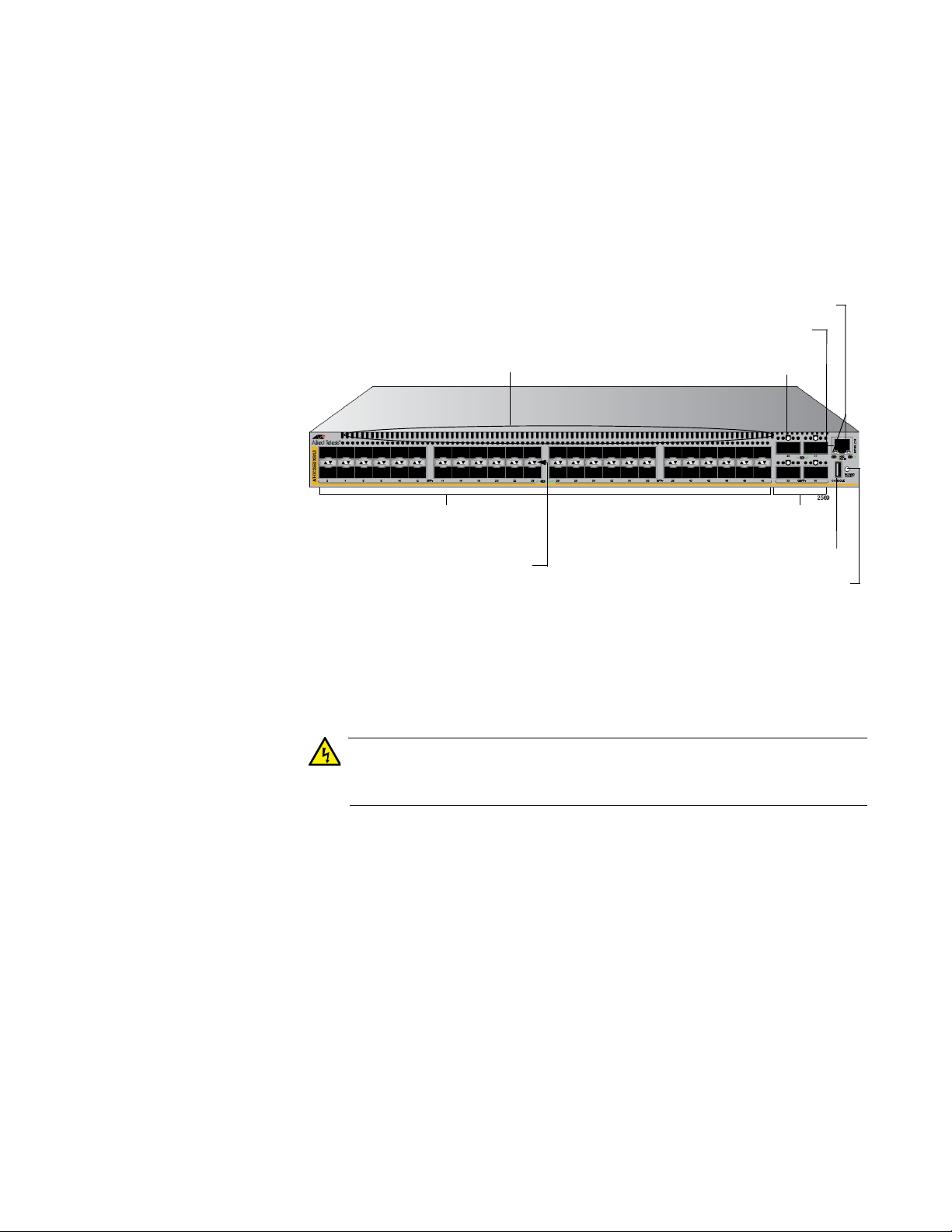
The front panel of the AT-DC2552XS / L3 is shown in Figure 1.
Figure 1. AT-DC2552XS / L3 Front Panel
Exhaust Air Vents - Air is forced through the chassis by the fan
modules and power supply modules and exits through the exhaust
air vents on the top of the front panel.
Air vents must not be blocked and must have free access to the
room ambient air for cooling. E6
SFP+ Slots - There are 48 SPF+ slots (ports 1 - 48) on the front
panel. Each port supports communication speeds up to 10Gbps.
The switch supports a variety of 10G SFP+ transceivers and direct
attach cables.
The AT-DC2552XS / L3 Enterprise Core Switch only supports
SFP+ transceivers in this product. Refer to “Installing SFP+
Transceivers and Cables” on page 70 for installation instructions of
the SFP+ transceivers.
19
Page 20

Chapter 1: Overview
Note
Note
Note
Note
Each SFP+ slot has a dust cover installed at the factory which
should be left in place until an SFP+ transceiver is installed.
SFP+ Slot LEDs - Each SFP+ slot has a corresponding LED which
displays the link and activity status of the port. See Figure 3 on
page 24 for the location of these LEDs and Table 2 on page 24 for
their functional description.
QSFP+ Slots - There are four QSFP+ slots which support
communication speeds up to 40 GB. These slots are numbered 49,
53, 57 and 61. Each slot may be configured as one 40 GB port or 4
X 10GB ports in the management software. See Figure 4 on page
25 for the location of these LEDs and Table 3 on page 25 for their
functional description. Refer to “Installing QSFP+ Transceivers and
Cables” on page 75 for installation instructions.
Each QSFP+ slot has a dust cover installed at the factory which
should be left in place until a QSFP+ transceiver is installed.
QSFP+ transceivers must be purchased separately. For more
information about the list of supported QSFP+ transceivers, refer to
“Optional SFP+ Transceivers” on page 17.
QSFP+ Slot LEDs - Each QSFP+ slot has a corresponding QSFP+
LED which displays the link and activity status of the QSFP + slots.
Refer to “QSFP+ Slot LEDs” on page 25 for the functional
description.
Power/Fault LED - The Status LED displays the overall status of
the chassis, power supply modules and fan modules. Refer to
“Power/Fault LED” on page 26 for the functional description.
Console Port - The console port is a standard RS-232 interface
using an USB interface. This port provides the capability to
manage the configuration and firmware of the switch locally
independent from the Ethernet network. Refer to “Connecting the
Console Port” on page 84 for more information.
An RS-232 cable (female USB / D-Sub 9 pin) cable is included with
the AT-DC2552XS / L3 shipping container.
20
Page 21

AT-DC2552XS / L3 Enterprise Core Switch Installation Guide
NET MGMT Port - This 10/100/1000BASE-T RJ-45 Ethernet port
provides the capability to manage the configuration and firmware of
the switch. You can obtain or forward information via the command
line interface (CLI) or SNMP interface. The port features auto MDI/
MDI-X and auto negotiation.
The cable requirements of the NET MGMT port are given in
Table 1.
Table 1. Twisted Pair Cable Specifications for the NET MGMT Port
Cable Type 10Mbps 100Mbps 1000Mbps
Standard TIA/EIA 568-B-
Yes Yes No
compliant Category 3 shielded
or unshielded cabling with 100
ohm impedance and a
frequency of 16 MHz.
Standard TIA/EIA 568-A-
Yes Yes Yes
compliant Category 5 or TIA/
EIA 568-B-compliant Enhanced
Category 5 (Cat 5e) shielded or
unshielded cabling with 100
ohm impedance and a
frequency of 100 MHz.
Standard TIA/EIA 568-B-
Yes Yes Yes
compliant Category 6 or 6a
shielded cabling.
NET MGMT Port LEDs - These two LEDs display the speed, link
and activity status of the NET MGMT Port. Refer to “NET MGMT
LED” on page 27 for more information.
21
Page 22
Chapter 1: Overview
Warning
Note
PS 1 FAN 1 FAN 2 PS 2
Blank
Covers
Slot Slot Slot Slot
Fan 1
LED
Fan 2
LED
[Top of Chassis]
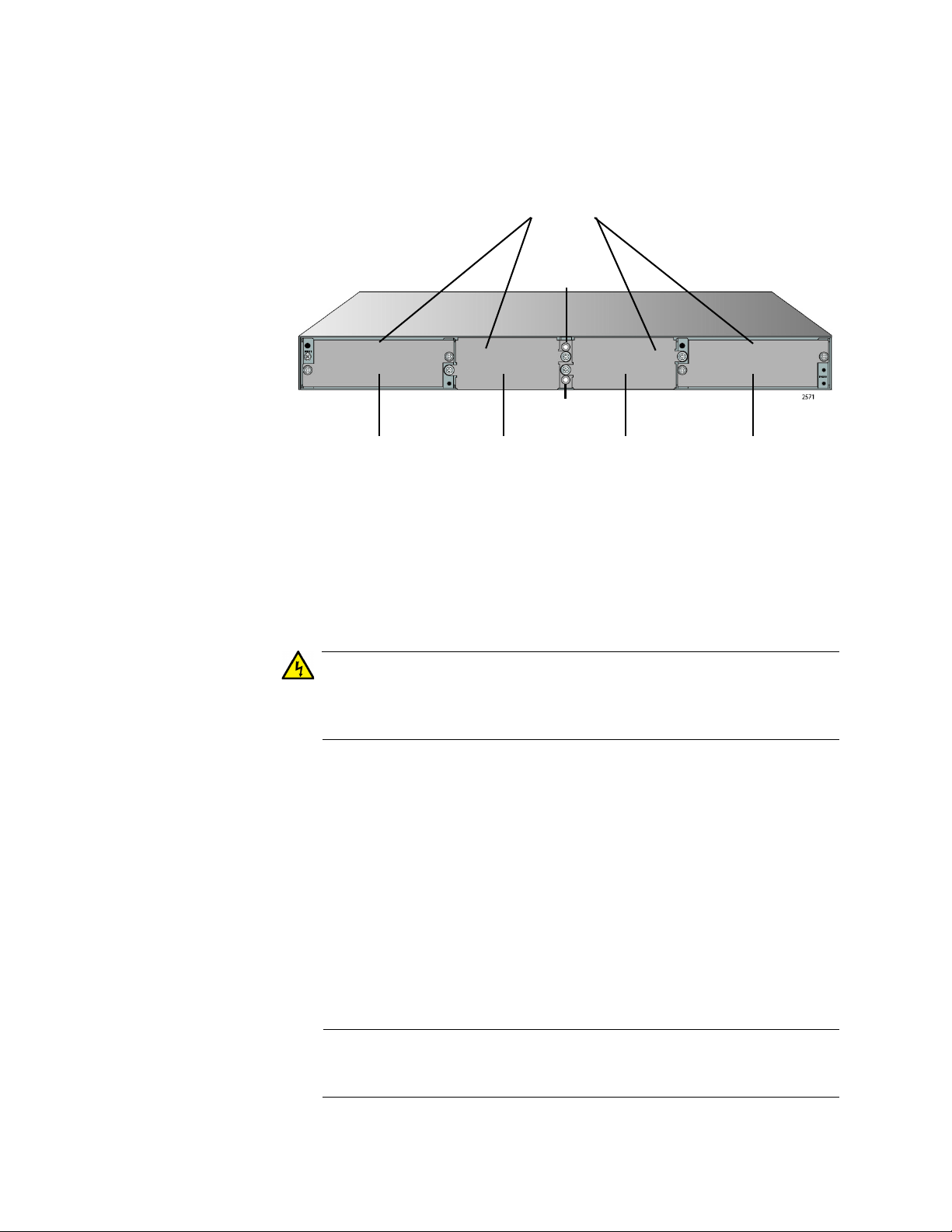
AT-DC2552XS / L3 Rear Panel
The rear panel of the AT-DC2552XS / L3 is shown in Figure 2.
Figure 2. AT-DC2552XS / L3 Rear Panel View
Blank Covers - When the switch is shipped from the factory, four
blank covers are installed.
- Two blank covers for the power supply slots (PS 1/PS 2)
- Two blank covers for the two fan module slots (FAN 1/FAN 2)
To insure proper cooling and air flow within the chassis, the blank
covers should not be removed unless the modules are installed in
their place. E76
The power unit slots (PS 1/PS 2) are for the installation of the AT-
PWR06 power supply module. These slots are located on the far
right and far left sides of the chassis.
A second AT-PWR06 power supply module may be installed for
redundancy, but is not required for normal operation of the switch.
With a redundant power supply configuration, you can replace one
of the two power supply modules without turning off the primary
power supply. Each AT-PWR06 power supply module that is
installed in the chassis is hot-swappable. Refer to “Installing and
Replacing AT-PWR06 Power Supply Module” on page 62 for the
installation procedure.
The AT-PWR06 power supply module is sold and packaged
separately from the AT-DC2552XS / L3 Enterprise Core Switch.
22
Page 23

AT-DC2552XS / L3 Enterprise Core Switch Installation Guide
Note
The fan module slots (FAN 1/FAN 2) are for the installation of the
AT-FAN06 fan module. These slots are located on the center right
and center left of the chassis.
Two AT-FAN06 fan modules are required in the chassis for normal
operation of the switch. Refer to “Installing and Replacing ATFAN06 Fan Module” on page 66 for the installation procedure.
The AT-FAN06 fan module is sold and packaged separately from
the AT-DC2552XS / L3 Enterprise Core Switch.
Fan LEDs - The fan LEDs FAN 1 (upper LED) / FAN 2 (lower LED)
display the status of the fan modules. They are located in the
center of the chassis between the fan module slots. Refer to
Table 6 on page 28 for the functional description of these LEDs.
23
Page 24
Chapter 1: Overview
LED Upper
L/A LED
Lower SFP+
Slot
Upper SFP+
Slot
LEDs
Here are the descriptions of the switch’s LEDs.
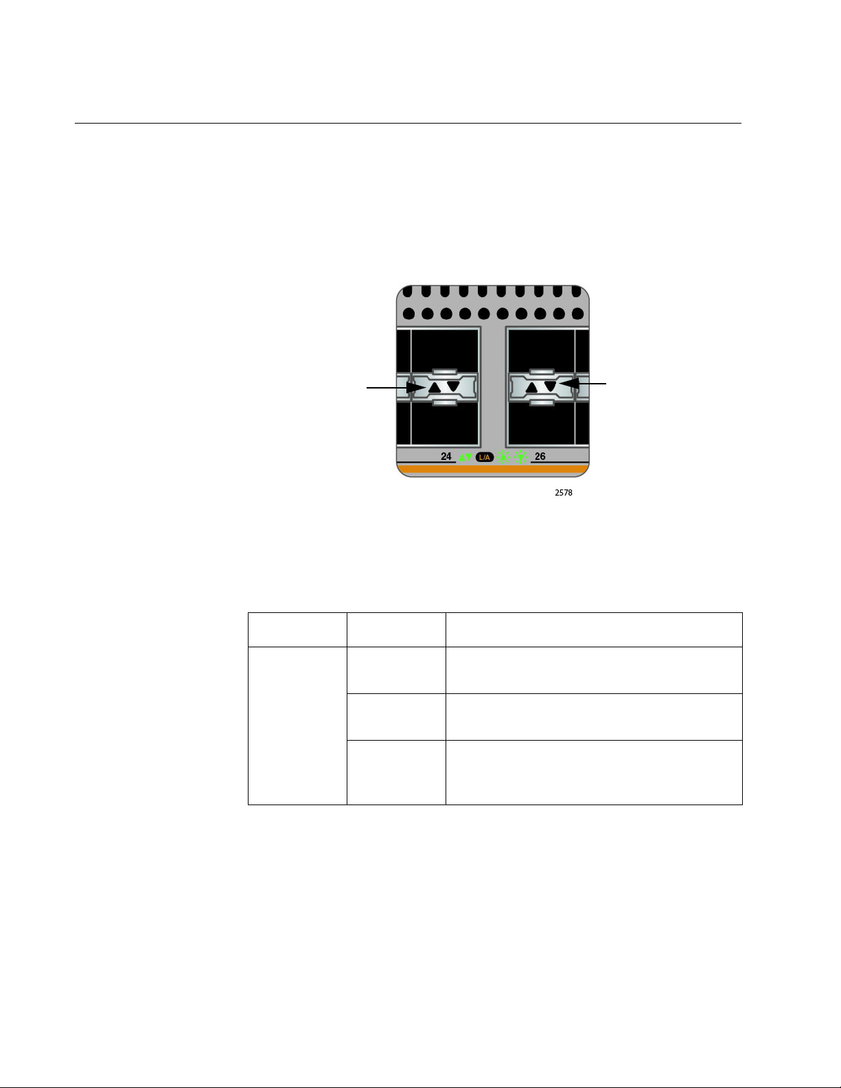
SFP+ Slot LED Each SFP+ slot has one Link/Activity LED. The LED is triangular in shape.
The triangle LED pointing up shows the status of the upper SFP+ slot
while the triangle LED pointing down shows the status of the lower SFP+
slot. These SFP+ slot LEDs are shown in Figure 3.
Figure 3. SFP+ Slot LEDs
The SFP+ slot LEDs are described in Table 2.
Table 2. SFP+ Slot LED
LED State Description
Solid green The SFP+ transceiver has established a
link to a network device.
Link/Activity
Flashing
green
Off
The SFP+ transceiver is receiving or
transmitting packets to a network device.
The SFP+ slot is empty or the SFP+
transceiver has not established a link to a
network device.
24
Page 25
AT-DC2552XS / L3 Enterprise Core Switch Installation Guide
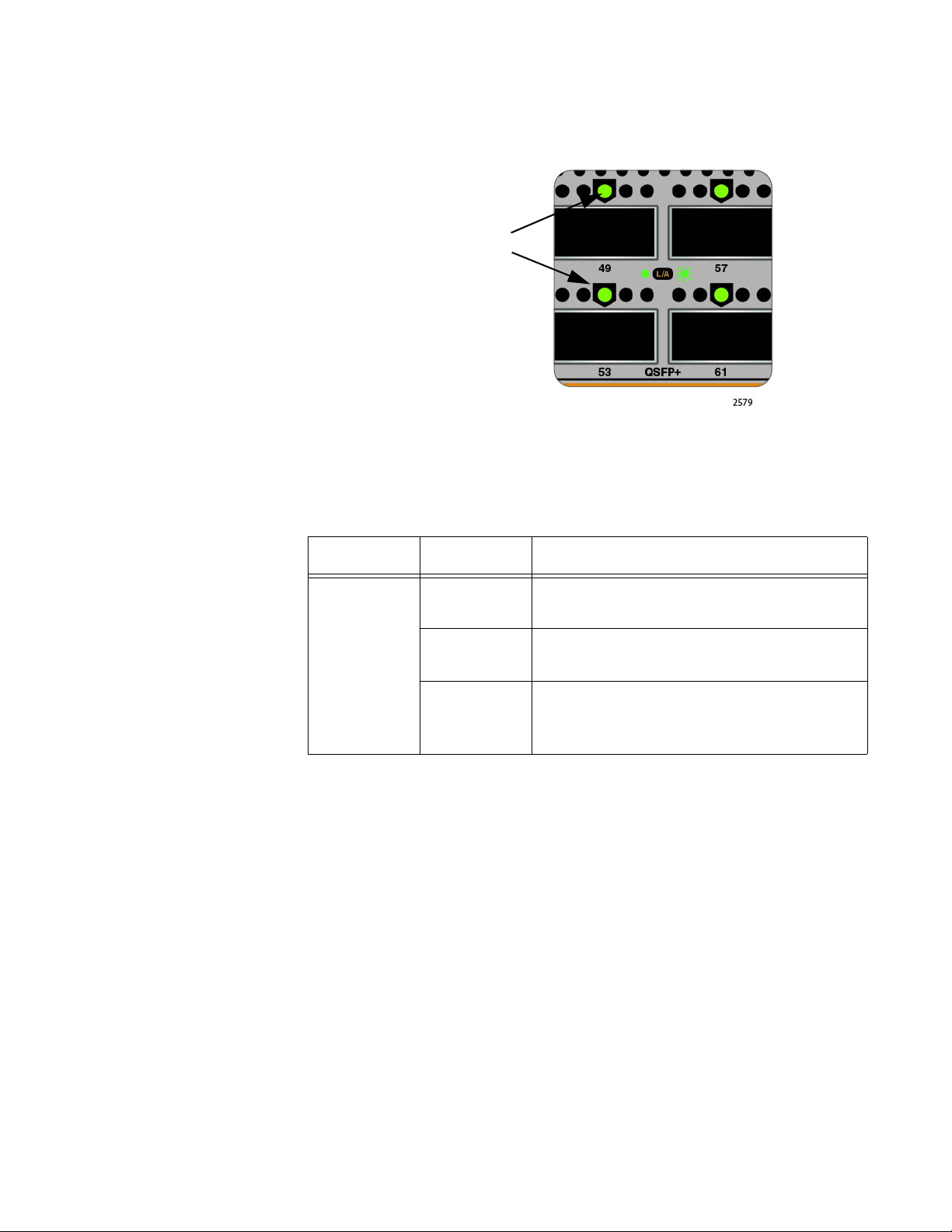
QSFP+ LEDs
QSFP+ Slot LEDs Each QSFP+ port has one link/activity LED labeled LINK/ACT. These
LEDs are shown in Figure 4.
Figure 4. QSFP+ LEDs
The QSFP+ LED is described in Table 3.
Table 3. QSFP+ LED
LED State Description
Solid green The QSFP+ transceiver has established a
link to a network device.
Link/Activity
Flashing
green
The QSFP+ transceiver is receiving or
transmitting packets to a network device.
The QSFP+ slot is empty or the QSFP+
Off
transceiver has not established a link to a
network device.
25
Page 26
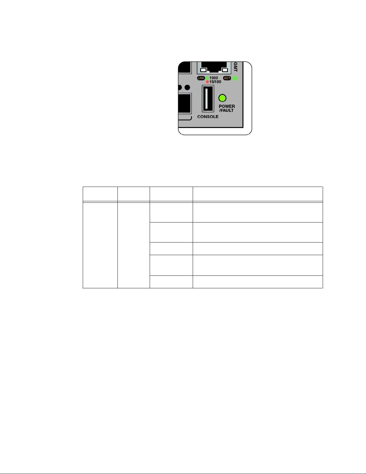
Chapter 1: Overview
Power/Fault LED The Power/Fault LED is shown in Figure 5.
Figure 5. Power/Fault LED
The Power/Fault LED is described in Table 4.
Table 4. Power/Fault LED Description
Location LED State Description
Front
Panel
POWER
/FAULT
Solid green Power is being supplied and the chassis is
operating normally.
Flashing
System is booting up.
green
Solid yellow Failure of one or more power supply fans.
Flashing
Only one PSU is powered up.
yellow
Off No power.
26
Page 27
AT-DC2552XS / L3 Enterprise Core Switch Installation Guide
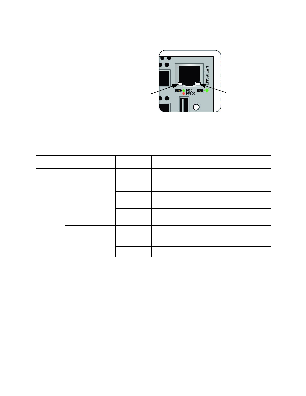
LINK
LED
ACT
LED
NET MGMT
The NET MGMT LEDs are shown in Figure 6.
LED
Figure 6. NET MGMT LEDs
The NET MGMT LEDs are described in Table 5.
Table 5. NET MGMT LED Descriptions
Location LED State Description
The NET MGMT port has established a link to
Front
Panel
ACT
(Right LED)
Solid green
Flashing
green
Off The NET MGMT port established a link to a
a network device, but no packets are being
transmitted or received.
The NET MGMT port is receiving or
transmitting packets to a network device.
network device.
LINK
(Left LED)
Solid green A valid 1G link is established on the port.
Solid yellow A valid 10/100M link is established on the port.
Off No link is established on the port.
27
Page 28
Chapter 1: Overview
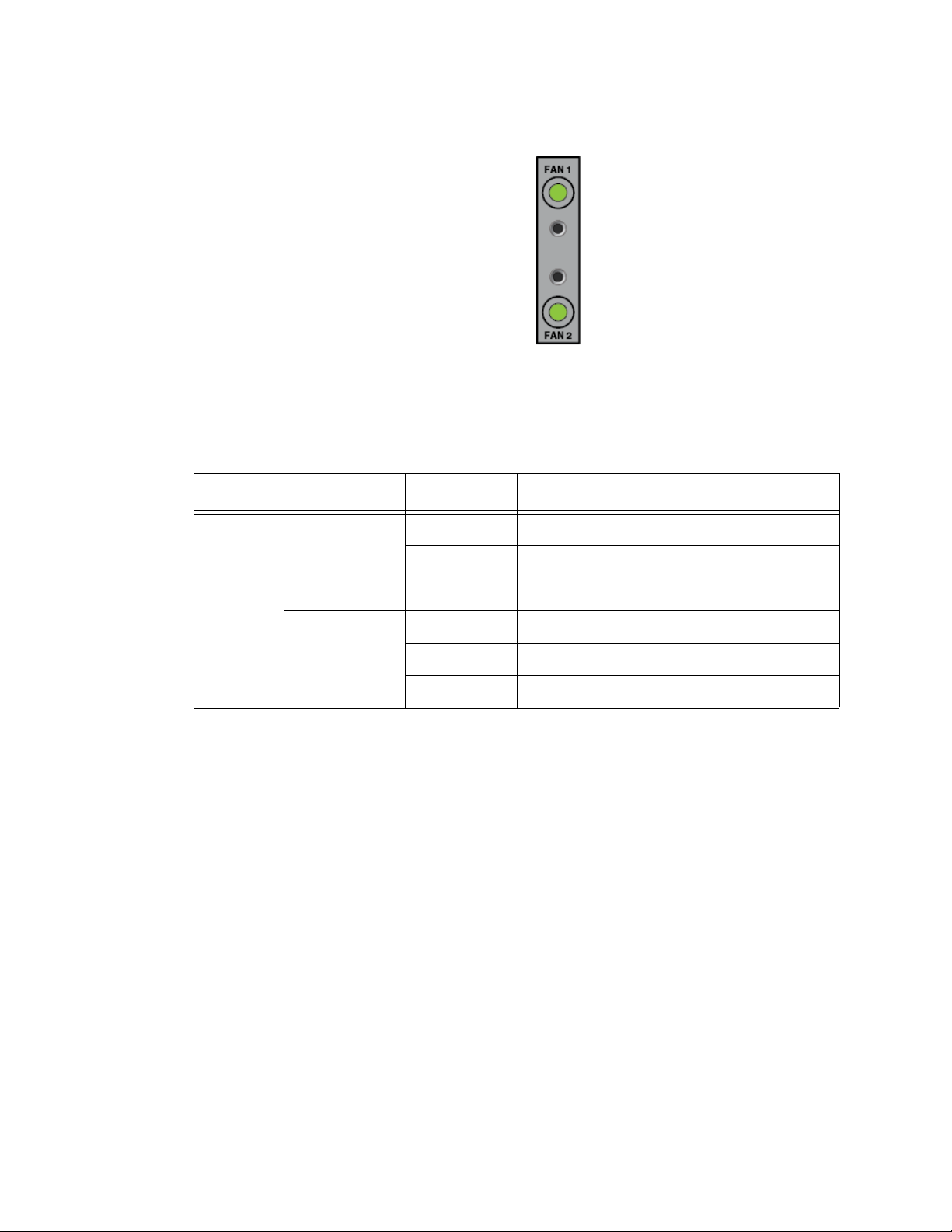
FAN Status LEDs The fan status LEDs are shown in Figure 7.
Figure 7. FAN Status LEDs
The fan status LEDs are described in Table 6.
Table 6. FAN Status LED Descriptions
Location LED State Description
Rear
Panel
FAN1
(top LED)
FAN2
(bottom LED)
Solid Green Fan operating normally.
Solid Red Fan is in failure mode.
Off No power is supplied to the fan module.
Solid Green Fan operating normally.
Solid Red Fan is in failure mode.
Off No power is supplied to the fan module.
28
Page 29
AT-DC2552XS / L3 Enterprise Core Switch Installation Guide
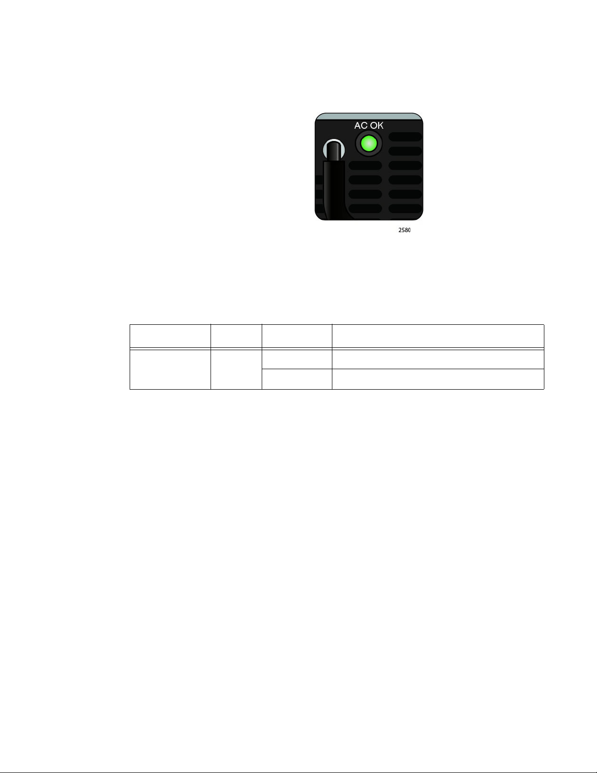
AC Power LED Each AT-PWR06 power supply module has an AC power (AC OK) LED.
This LED is shown in Figure 8.
Figure 8. AC Power LED
The AC Power LED is described in Table 7.
Table 7. AC Power LED Description
Location LED State Description
Power Supply
Module Panel AC OK
Solid Green AC power is supplied to power supply.
Off No AC power is supplied to power supply.
29
Page 30

Chapter 1: Overview
Note
Note
Console Port
The Console port is a USB connector located on the front panel. See
Figure 1 on page 19 for its location. It is used to locally configure the
features and parameter settings of the switch. This type of management
uses the RS-232 serial communications protocol. It is commonly referred
to as local or out-of-band management because it is not connected over
an Ethernet network. To perform local management, you must be at the
location of the switch and must use the management cable included with
the switch.
Refer to “Console Port Pinouts” on page 95 for USB pin orientation
and the signal functions assigned to each pin.
To establish a local management session with the switch, connect a
terminal or a personal computer with a terminal emulation program to the
Console port using the management cable provided with the switch. This
cable has a USB connector on one end and a DB-9 (D-sub 9-pin)
connector on the other.
The Console port is configured at the factory to the following
specifications:
Default baud rate: 9600 bps (Range is 9600 to 115200 bps)
Data bits: 8
Parity: None
Stop bits: 1
Flow control: None
These settings are for a DEC VT100 or ANSI terminal, or an
equivalent terminal emulation program.
30
Page 31

AT-PWR06 Power Supply Module
Warning
Warning
Captive Intake
Handle
Power
Connector
AC Power
LED
Screws
Air Vents
The AT-DC2552XS / L3 Enterprise Core Switch is powered by one ATPWR06 power supply module. A second AT-PWR06 power supply module
may be installed for redundancy. The power supply module has an AC
connector on the power supply module panel and is installed by the user in
slot PS1 or slot PS2. The location of these slots is shown in Figure 2 on
page 22.
When two power supplies are installed and operating, only one power
supply is active at a time. The second power supply operates in a
redundant state and is automatically activated by the switch if the active
power supply loses power or fails. The change-over is instantaneous and
has no effect on the Ethernet data being passed through the chassis.
Power cord is used as a disconnection device. To de-energize
equipment, disconnect the power cord. E3
AT-DC2552XS / L3 Enterprise Core Switch Installation Guide
This unit might have more than one power cord. To reduce the risk of
electric shock, disconnect all power cords before servicing the unit.
E30
Refer to “Power Specifications” on page 94 for the input power
specifications.
A view of the AT-PWR06 power supply module is shown in Figure 9.
Figure 9. AT-PWR06 Power Supply Module
31
Page 32

Chapter 1: Overview
Warning
The components of the AT-PWR06 power supply module (see Figure 9 on
page 31) are as follows:
Power connector - The AC power cable plugs into this connector.
Regional AC power cables are provided in the AT-PWR06 power
supply module shipping box. Refer to “Powering On the Switch” on
page 80 and “Turning Off the Switch” on page 82.
AC Power LED - This LED displays the status of the power supply
module. Refer to “AC Power LED” on page 29 for a functional
description of this LED.
Intake Air Vents - The AT-PWR06 power supply module has two
fans which pull air into the power supply module through the intake
air vents to cool the power supply and the chassis components.
The air is discharged through the exhaust air vents on the top of
the chassis front panel. See Figure 1 on page 19 for the location of
the exhaust vents.
Air vents must not be blocked and must have free access to the
room ambient air for cooling. E6
Captive screws - These two screws secure the power supply
module to the chassis frame. Refer to “Installing and Replacing
AT-PWR06 Power Supply Module” on page 62 for the power
supply installation procedure.
Handle - The handle is used to physically push or pull the AT-
PWR06 power supply module when it is inserted or removed.
Refer to “Installing and Replacing AT-PWR06 Power Supply
Module” on page 62 for the power supply installation procedure.
32
Page 33

AT-FAN06 Fan Module
Warning
Captive Screws
Intake Air VentsHandles
Installation of two AT-FAN06 fan modules are required in the
AT-DC2552XS / L3. Refer to “Installing and Replacing AT-FAN06 Fan
Module” on page 66 for the fan installation procedure.
Each AT-FAN06 fan module is equipped with two forced-air cooling fans
The fans push air through the chassis from the rear to the front. The ATFAN06 fan module is ordered and shipped separately from the
AT-DC2552XS / L3 Enterprise Core Switch.
A view of the AT-FAN06 fan module is shown in Figure 10.
AT-DC2552XS / L3 Enterprise Core Switch Installation Guide
Figure 10. AT-FAN06 Fan Module
The components of the AT-FAN06 fan module are as follows:
Captive screws - The two captive screws secure the fan module to
the chassis frame.
Handles - The two handles are used to physically push or pull the
AT-FAN06 fan module into and out of the chassis.
Intake Air Vents - The AT-FAN06 fan module has two fans which
pull air through the intake air vents to cool the chassis components.
The air is discharged through the front panel exhaust air vents. See
Figure 1 on page 19 for the location of the exhaust vents.
Air vents must not be blocked and must have free access to the
room ambient air for cooling. E6
33
Page 34

Chapter 1: Overview
34
Page 35

Chapter 2
VCStack Overview
The chapter contains the following sections:
“VCStack Introduction” on page 36
“Stack Formation” on page 42
35
Page 36

Chapter 2: VCStack Overview
Caution
VCStack Introduction
This chapter describes Virtual Chassis Stacking (VCStack), its features,
and basic connection examples.
VCStack is a group of physically separate switches that are configured to
operate as a single logical switch. In order to function as a VCStack, its
component switches are connected using high-speed stacking links.
Features of
Virtual Chassis
Stacking
Creating a VCStack greatly eases network management, because you
can configure all the stacked devices via a single IP address. Creating a
VCStack will often eliminate your need to configure protocols such as
VRRP and Spanning Tree. VCStack also enables you to create highly
resilient networks. This resiliency can be applied in several ways.
Within the stack itself, switch interconnection is via two links. The second
link is able to provide an alternative data path, thus the stack will continue
to function if a single switch fails. Degraded performance might occur
however, due to the reduced VCStack bandwidth.
User ports can also be made extremely resilient by utilizing link
aggregation. Aggregated links can span ports, modules, and even
switches within the stack. Creating aggregated links that span multiple
switches within a stack creates an extremely resilient configuration.
Communication will still exist even if a switch and its aggregated ports fail.
See Figure 13 on page 39.
Stack operation is only supported if STACK VIRTUAL-MAC is
enabled.
E72
For more information, refer to the STACK VIRTUAL-MAC command
in the AT-DC2552XS / L3 Management Software Command Line
Interface User’s Guide.
VCStack Capable
36
Switches
VCStack is supported on the following Allied Telesis switch types:
SwitchBlade® x8100 Series (VCStack Plus)
x900-24XT, x900-24XS, x900-24XT-N
x900-12XT/s
SwitchBlade® x908
AT-DC2552XS / L3
x610 Series
x510 Series
IX5-28GPX
Page 37

AT-DC2552XS / L3 Enterprise Core Switch Installation Guide
Note
x310 Series
You can only create VCStacks using switches from within the same
product group, for example, all AT-DC2552XS / L3 switches, or all
x610 Series switches.
Stacking connectivity and functionality varies slightly between switch
types. Your AT-DC2552XS / L3 switch can support a maximum of two
devices per stack. Consult the appropriate software reference for stacking
functionality of other Allied Telesis switches.
The Physical
Stack
A VCStack can consist of a maximum of two individual AT-DC2552XS / L3
switches, interconnected via high-speed stacking links (QSFP+ ports 49,
53, 57, or 61). A stack always has a primary stack member called the
stack master (displayed in the show commands as the active master). The
remaining switch then becomes an ordinary member of the stack, and is
referred to as the backup member.
VCStack Cables and Connections
Stack members are interconnected via the QSFP+ ports 49, 53, 57, or 61.
These ports are shown in Figure 11.
Figure 11. Stacking Ports
The stacking cables must connect ports that have the same port number.
A stack will form regardless of which port numbers are used for linking, as
long as the same numbers are linked together. This means that you can
connect your stack using any two of the following pairs of ports:
port 49 connected to port 49
port 53 connected to port 53
port 57 connected to port 57
port 61 connected to port 61
37
Page 38

Chapter 2: VCStack Overview
Figure 12 shows an example configuration. In this example, the QSFP+
stacking ports labeled 49 and 61 on one member are connected to the
QSFP+ stacking ports labeled 49 and 61 on the other stack member,
respectively.
Figure 12. AT-DC2552XS / L3 Stacking Configuration Example
Resilient Stacked
Topology
Where network connectivity uptime is a major criteria, you can use virtual
chassis stacking to create highly reliable network configurations. The
network shown in Figure 13 on page 39 employs redundant links and
switches to create a stacked network that offers extremely reliable user
connectivity.
Employing link aggregation, rather than spanning tree, to manage the
parallel paths enables the bandwidth of both data links to be utilized under
normal conditions while enabling a single data link to operate should its
partner link fail.
38
Page 39

AT-DC2552XS / L3 Enterprise Core Switch Installation Guide
Note
Figure 13. VCStack Resilient Stacked Topology Example
The network depicted in Figure 13 employs two SwitchBlade® x908
switches to form an expandable network core. These switches are stacked
and so appear as a single logical switch
Smaller switches, such as the AT-DC2552XS / L3, can be also be
used to form the stacked core or stacked distribution.
This network topology supplies multiple dual connections to a number of
downstream distribution switches that can in turn connect to user devices.
Similarly, the dual network paths provide very reliable connectivity to the
servers portion of the network.
39
Page 40

Chapter 2: VCStack Overview
DC2552XS/L3
DC2552XS/L3
DC2552XS/L3
DC2552XS/L3
Resiliency Link
The resiliency link carries no network data. Its function is to provide
additional stack status information to enable the stack members to more
accurately decide whether it is appropriate for one of them to take over the
role of stack master if the existing master fails.
A resiliency link can be created using a single physical connection
between two eth0 (NET MGMT) ports, or it can use a VLAN (resiliency link
VLAN) to which the switch ports can be attached.
To create a resiliency link using eth0 (NET MGMT) ports, connect a
standard twisted pair LAN cable (either straight through, or crossover—
MDI-MDIX negotiation is supported on these ports) between the two eth0
(NET MGMT) ports on both devices. Once you have connected the cable,
you can run the STACK RESILIENCYLINK command to create the
resiliency link.
Resiliency Link Configurations via Switch Ports
Two resiliency-link configurations that use switch ports are shown below.
Figure 14 shows the resiliency link connecting in a ring topology, while
Figure 15 on page 41 shows the resiliency link connecting to the switch
ports via a network hub. In both configurations, the resiliency link
connections are made using a designated VLAN running over switch-port
connections between each stack member. For more information on using
the resiliency link commands, refer to the STACK RESILIENCYLINK and
SWITCHPORT RESILIENCYLINK commands in the AT-DC2552XS / L3
Management Software Command Line Interface User’s Guide.
40
Figure 14. Resiliency Link Connecting to Switch Ports Over the Resiliency
Link VLAN
Page 41

AT-DC2552XS / L3 Enterprise Core Switch Installation Guide
DC2552XS/L3
Switches
DC2552XS/L3
Switches
Figure 15. Resiliency Link Connecting to Switch Ports Over the Resiliency
Link VLAN Using a Network Hub
41
Page 42

Chapter 2: VCStack Overview
Stack Formation
As previously mentioned, a VCStack always contains a stack (active)
master and a stack member (backup). To be part of a stack, a switch must
connect to the other potential stack member via dedicated stacking ports.
See Figure 16.
Figure 16. Stacking Ports
The Role of the
Stack Master
Once the switches have been physically connected, powering the
members on sets off a number of automatic processes that enable the
stack members to detect the presence of one another and form
themselves into a VCStack.
Long-Distance Stacking
You can extend the distance between stacked units up to the maximum
distance supported by the particular QSFP+ port you are using. This
capability enables you to create a stack of 2 geographically separated
switches as a single stack.
In addition to being a member of its VCStack, the stack master manages
functions such as software version control and distribution, routing
processing, and network management.
Selecting the Stack Master
The stack members are able to automatically select which switch will
become the stack master. This selection is based on two components:
1. The stack member’s priority setting.
42
2. The stack member’s MAC address.
For both components, the lower the number, the higher the priority will be.
To set the stack priority, run the STACK PRIORITY command. Note that
changes to these settings will not take effect until the next master reelection. To display these components run the SHOW STACK command.
Page 43

AT-DC2552XS / L3 Enterprise Core Switch Installation Guide
Note
Note
Note
The master is the switch with the lowest priority setting, or if the priority
settings are equal, the switch with the lowest MAC address will become
the stack master. When a stack member is initially booted, its priority value
defaults to 128. Therefore, if both switches retain their defaults, then the
stack master will be determined by MAC address comparison.
The stack also assigns a stack ID number to each member. This number
provides a unique reference number for switches within the stack; it plays
no part in selecting the stack master. The stack ID is used as the first digit
of the three component port identifier numbers. For example, port number
2.0.14 has the stack ID of 2.
The stack ID number assignment is important to remember when
using configuration scripts. You should ensure that you modify your
configuration scripts to match any changes you have made to the
stack ID assignments.
The ability to independently set both a stack member’s priority and
its ID means that the stack master does not need to have an ID of 1;
although configuration is simplified by arranging for ID 1 to be the
device with the lowest priority value - and thereby forcing it to be the
stack master. If you create a stack using new switches, the following
(simplified) process should ensure that the master member has an
ID of 1.
New switches are shipped with a Stack Member ID of 1 and a
priority of 128. If two such switches are created as a stack, the
switch with the lowest MAC address will be selected to be the stack
master (because all priority settings are 128). The remaining stack
member device will then reboot. The stack master does not reboot
and retains its Stack Member ID of 1.
You can change the stack ID by using the command stack renumber.
Common Stack Configuration
Once the switches have configured themselves into a VCStack, they all
share the same configuration information and startup scripts.
43
Page 44

Chapter 2: VCStack Overview
44
Page 45

Chapter 3
Beginning the Installation
The chapter contains the following sections:
“Installation Overview” on page 46
“Reviewing Safety Precautions” on page 47
“Planning the Installation” on page 52
“Unpacking the Switch” on page 53
45
Page 46

Chapter 3: Beginning the Installation
Installation Overview
Table 8 lists the installation procedures for the AT-DC2552XS / L3
Enterprise Core Switch. The procedures should be performed in the order
presented in the table.
1 “Reviewing Safety Precautions” on page 47
2 “Planning the Installation” on page 52
3 “Unpacking the Switch” on page 53
4 “Installing the Switch on a Desktop” on page 58 OR
5 “Installing Power Supply Module” on page 62
Table 8. Installation Procedures
Step Procedure
“Installing the Switch in an Equipment Rack” on page 59
6 “Installing Fan Module” on page 66
7 “Installing SFP+ Transceivers and Cables” on page 70
8 “Installing QSFP+ Transceivers and Cables” on page 75
9 “Powering On the Switch” on page 80
10 “Managing the Switch” on page 83
46
Page 47

Reviewing Safety Precautions
Note
Warning
Warning
Warning
Warning
Warning
Please review the following safety precautions before you begin to install
the switch.
The indicates that a translation of the safety statement is
available in a PDF document titled Translated Safety Statements on
the Allied Telesis website at www.alliedtelesis.com/support.
Class 1 Laser product. L1
AT-DC2552XS / L3 Enterprise Core Switch Installation Guide
Do not stare into the laser beam. L2
Do not look directly at the fiber optic cable ends or inspect the cable
ends with an optical lens. L6
Laser Safety: EN60825-1 L7
To prevent electric shock, do not remove the cover. No userserviceable parts inside. This unit contains hazardous voltages and
should only be opened by a trained and qualified technician. To
avoid the possibility of electric shock, disconnect electric power to
the product before connecting or disconnecting the LAN cables.
E1
47
Page 48

Chapter 3: Beginning the Installation
Warning
Warning
Warning
Note
Caution
Warning
Note
Do not work on equipment or cables during periods of lightning
activity. E2
Power cord is used as a disconnection device. To de-energize
equipment, disconnect the power cord. E3
Class I Equipment. This equipment must be earthed. The power
plug must be connected to a properly wired earth ground socket
outlet. An improperly wired socket outlet could place hazardous
voltages on accessible metal parts. E4
Pluggable Equipment. The socket outlet shall be installed near the
equipment and shall be easily accessible. E5
Air vents must not be blocked and must have free access to the
room ambient air for cooling. E6
Operating Temperature. This product is designed for a maximum
ambient temperature of 40° degrees C. E7
All Countries: Install product in accordance with local and National
Electrical Codes. E8
48
Page 49

AT-DC2552XS / L3 Enterprise Core Switch Installation Guide
Warning
Note
Caution
Warning
Note
Caution
Only trained and qualified personnel are allowed to install or replace
this equipment. E14
Circuit Overloading: Consideration should be given to the
connection of the equipment to the supply circuit and the effect that
overloading of circuits might have on overcurrent protection and
supply wiring. Appropriate consideration of equipment nameplate
ratings should be used when addressing this concern. E21
Risk of explosion if battery is replaced by an incorrect type. Replace
only with the same or equivalent type recommended by the
manufacturer. Dispose of used batteries according to the
manufacturer’s instructions.
Attention: Le remplacement de la batterie par une batterie de type
incorrect peut provoquer un danger d’explosion. La remplacer
uniquement par une batterie du même type ou de type équivalent
recommandée par le constructeur. Les batteries doivent être
éliminées conformément aux instructions du constructeur. E22
Mounting of the equipment in the rack should be such that a
hazardous condition is not created due to uneven mechanical
loading. E25
Use dedicated power circuits or power conditioners to supply reliable
electrical power to the device. E27
The chassis may be heavy and awkward to lift. Allied Telesis
recommends that you get assistance when mounting the chassis in
an equipment rack. E28
49
Page 50

Chapter 3: Beginning the Installation
Warning
Note
Caution
Warning
Caution
Warning
This unit might have more than one power cord. To reduce the risk
of electric shock, disconnect all power cords before servicing the
unit. E30
If installed in a closed or multi-unit rack assembly, the operating
ambient temperature of the rack environment may be greater than
the room ambient temperature. Therefore, consideration should be
given to installing the equipment in an environment compatible with
the manufacturer’s maximum rated ambient temperature (Tmra).
E35
Installation of the equipment in a rack should be such that the
amount of air flow required for safe operation of the equipment is not
compromised. E36
Reliable earthing of rack-mounted equipment should be maintained.
Particular attention should be given to supply connections other than
direct connections to the branch circuits (e.g., use of power strips).
E37
The unit does not contain serviceable components. Please return
damaged units for servicing. E42
When you remove an SFP module from this product, the case
temperature of the SFP may exceed 40° C (158° F). Exercise
caution when handling with unprotected hands. E43
50
Page 51

AT-DC2552XS / L3 Enterprise Core Switch Installation Guide
Caution
Caution
Warning
Warning
Warning
Warning
To insure proper cooling and airflow within the chassis, a blank
cover should be installed if a module is not present in the chassis
E70
Stack operation is only supported if STACK VIRTUAL-MAC is
enabled. E72
To operate this product, two fan modules must be installed.
Operation with one fan module will cause the chassis to overheat.
E73
To insure proper cooling and air flow within the chassis, the blank
covers should not be removed unless the modules are installed in
their place. E76
In a domestic environment this product may cause radio interference
in which case the user may be required to take adequate measures.
E84
A transceiver can be damaged by static electricity. Be sure to
observe all standard electrostatic discharge (ESD) precautions,
such as wearing an antistatic wrist strap, to avoid damaging the
device. E92
51
Page 52

Chapter 3: Beginning the Installation
Planning the Installation
The AT-DC2552XS / L3 Enterprise Core Switch can be installed on a
desktop or in a 19 inch equipment rack. Observe these general
requirements when planning the installation of the switch.
Check that the power outlets for the switches are located near the
Verify that the site provides easy access to the ports on the front of
Check that the site allows for adequate air flow around the units
Do not place objects on top of the switch.
Do not expose the switch to moisture or water.
devices and are easily accessible.
the switch. This will make it easy for you to connect and disconnect
cables, as well as view the port LEDs.
and through the cooling vents on the front and rear panels. (The
airflow direction is from fan modules on the rear panel through the
unit to the port side on the front panel.)
Make sure the site is a dust-free environment.
Use dedicated power circuits or power conditioners to supply
reliable electrical power to the network devices.
Do not install the switch in a wiring or utility box because it will
overheat and fail from inadequate airflow.
If the unit is to be installed in an equipment rack, check that the
rack is safely secured and will not tip over. Devices in a rack
should be installed starting at the bottom, with the heavier devices
near the bottom of the rack.
52
Page 53

Unpacking the Switch
Note
Note
One AT-DC2552XS / L3 switch
Two rack mounting brackets with
eight bracket screws
Desktop mounting feet
One 2 m (6.6 ft) local management cable with
USB and DB-9 (D-sub 9-pin) connectors.
Refer to the following figures in this section to verify the contents of the
shipping containers:
”AT-DC2552XS/L3 Switch”
“AT-PWR06 Power Supply” on page 54
“AT-FAN06 Fan Module” on page 55
AT-DC2552XS / L3 Enterprise Core Switch Installation Guide
If any item in a shipping container is missing or damaged, contact
your Allied Telesis sales representative for assistance.
AT-DC2552XS/
L3 Switch
The contents of the AT-DC2552XS / L3 shipping box are listed in Figure
17.
Figure 17. Contents of the AT-DC2552XS / L3 Shipping Box
You should retain the original packaging material in the event you
need to return the unit to Allied Telesis.
53
Page 54

Chapter 3: Beginning the Installation
Note
Note
Note
One AT-PWR06 Power Supply Module
One regional AC power cord
AT-PWR06
Power Supply
The contents of the AT-PWR06 power supply module shipping box are
listed in Figure 18.
Figure 18. Contents of the AT-PWR06 Power Supply Module Shipping
Box
The AT-DC2552XS / L3 switch can operate with one power supply
module installed. You may elect to install a second power supply
module for redundancy.
The AT-PWR06 power supply module is sold and packaged
separately from the AT-DC2552XS / L3 Enterprise Core Switch.
Contact your local Allied Telesis representative for more information.
You should retain the original packaging material in the event you
need to return the unit to Allied Telesis.
54
Page 55

AT-DC2552XS / L3 Enterprise Core Switch Installation Guide
Note
Note
Note
One AT-FAN06 FAN Module
AT-FAN06 Fan
Module
The contents of the AT-FAN06 fan module shipping box is shown in Figure
19.
Figure 19. Contents of the AT-FAN06 Fan Module Shipping Box
The AT-DC2552XS / L3 switch must have two fan modules installed
for proper operation.
The AT-FAN06 fan module is sold and packaged separately from
the AT-DC2552XS / L3 Enterprise Core Switch. Contact your local
Allied Telesis representative for more information.
You should retain the original packaging material in the event you
need to return the unit to Allied Telesis.
55
Page 56

Chapter 3: Beginning the Installation
56
Page 57

Chapter 4
Installing the Switch and Modules
You may install the AT-DC2552XS / L3 Switch on a desktop or in a
standard 19 inch equipment rack. In addition, you must install at least one
AT-PWR06 power supply module and two AT-FAN06 fan modules in the
switch chassis.
Here are the installation procedures in this chapter:
“Installing the Switch on a Desktop” on page 58
“Installing the Switch in an Equipment Rack” on page 59
“Installing and Replacing AT-PWR06 Power Supply Module” on
page 62
“Installing and Replacing AT-FAN06 Fan Module” on page 66
57
Page 58

Chapter 4: Installing the Switch and Modules
Note
[Bottom of Switch]
Installing the Switch on a Desktop
To install the switch on a desktop, perform the following procedure:
To install the switch in a rack, refer to “Installing the Switch in an
Equipment Rack” on page 59.
1. Remove all equipment from the package and store the packaging
material in a safe place.
2. Turn the switch over and place it on a table.
3. Remove the adhesive backing from the rubber feet.
4. Four rubber feet are provided in the switch shipping container, see
Figure 17 on page 53. Attach the feet to the bottom of the switch in the
corners as shown in Figure 20.
58
Figure 20. Attaching the Rubber Feet
5. Turn the switch over again and place it on a flat, secure surface (such
as a desk or table) leaving ample space around the unit for ventilation.
6. The next step in the installation process is installing the power supply
module(s). Go to “Installing Power Supply Module” on page 62 for the
installation procedure.
Page 59

AT-DC2552XS / L3 Enterprise Core Switch Installation Guide
Note
Installing the Switch in an Equipment Rack
To install the switch on a desktop, refer to “Installing the Switch on a
Desktop” on page 58.
When installing the AT-DC2552XS / L3 switch in a 19 inch rack, it must
always be mounted horizontally with the top side up; see Figure 1 on page
19 and Figure 2 on page 22. The switch can be oriented and positioned in
the rack in four different ways. This is determined by where you install the
two rack mount brackets that are provided. The four possible positions for
the brackets are:
Flush with the rear of chassis so the rear of the chassis is even
with the vertical rack rails.
Offset by 17.5 cm from the rear of the chassis so that the rear of
the chassis protrudes beyond the vertical rack rails by 17.5 cm.
Flush with the front of chassis so the front of the chassis is even
with the vertical rack rails.
Offset by 17.5 cm from the front of the chassis so that the front of
the chassis protrudes beyond the vertical rack rails by 17.5 cm.
These four possible bracket locations are illustrated in Figure 21.
Figure 21. Possible Bracket Locations
59
Page 60

Chapter 4: Installing the Switch and Modules
Note
Caution
This procedure requires the following items:
Perform this procedure to install the switch in a 19-inch equipment rack:
1. Secure the two rack mount brackets to the sides of the switch using
Eight bracket screws (included with the switch)
Two equipment rack brackets (included with the switch)
Cross-head screwdriver (not provided)
Four standard equipment rack screws (not provided)
If you have installed the rubber feet, remove the rubber feet by
prying them off the bottom of the chassis with a flat-bladed tool.
the eight bracket screws provided. Figure 22 shows an example of
mounting the rack mount bracket on the rear of the chassis and with
the bracket flush to the rear panel. See Figure 21 on page 59 for other
possible bracket mounting positions on the chassis.
60
Figure 22. Attaching the Brackets to Switch
The chassis may be heavy and awkward to lift. Allied Telesis
recommends that you get assistance when mounting the chassis in
an equipment rack. E28
Page 61

AT-DC2552XS / L3 Enterprise Core Switch Installation Guide
2. Have another person hold the switch in the equipment rack while you
secure it using standard rack mount screws (not provided).
Figure 23. Mounting the Switch in an Equipment Rack
61
Page 62

Chapter 4: Installing the Switch and Modules
Installing and Replacing AT-PWR06 Power Supply Module
The AT-PWR06 power supply module may be installed in one of the two
power supply slots - PSU1 or PSU2. See Figure 2 on page 22 for the
location of these slots.
The AT-DC2552XS / L3 Enterprise Core Switch can operate under full
load with one power supply module installed. However, if you want power
supply redundancy, a second power supply may be installed.
There is no functional difference between the two available power supply
slots. Operation of the AT-DC2552XS / L3 is the same when installed in
either slot. If you want to use only one power supply, Allied Telesis
recommends that you install it in the PSU1 slot.
The following procedures are included in this section:
“Installing Power Supply Module”
“Replacing Power Supply Module” on page 64
Installing Power
Supply Module
“Installing Power Supply Blank Cover” on page 65
Install the AT-PWR06 power supply module by performing the following
procedure:
1. Identify the power supply slot where you are installing the AT-PWR06
power supply module.
2. Loosen the captive screw on the blank cover panel of the power
supply slot blank cover and remove the cover. See Figure 24.
62
Figure 24. Loosen Power Supply Captive Screws
3. Store the blank cover in a safe place for future use.
Page 63

AT-DC2552XS / L3 Enterprise Core Switch Installation Guide
Warning
To insure proper cooling and air flow within the chassis, the blank
covers should not be removed unless the modules are installed in
their place. E76
4. Slowly insert the AT-PWR06 power supply module into the PSU slot
until it is flush with the rear of the chassis. See Figure 25.
Figure 25. Insert AT-PWR06 Module Into Chassis
63
Page 64

Chapter 4: Installing the Switch and Modules
Caution
5. Tighten the captive screws to fasten the power supply module to the
chassis. See Figure 26.
Figure 26. Tighten AT-PWR06 Captive Screws
Replacing Power
Supply Module
6. The next step in the installation process is installing the fan modules.
Go to “Installing Fan Module” on page 66 for the installation
procedure.
The AT-PWR06 power supply module is hot swappable within the chassis
assuming a second AT-PWR06 power supply module is already installed
and operating.
Perform the following procedure to replace a AT-PWR06 power supply
module:
To insure proper cooling and airflow within the chassis, a blank
cover should be installed if a module is not present in the chassis.
E70
Refer to “Installing Power Supply Blank Cover” on page 65.
1. Turn off the power to the AT-PWR06 power supply module by
disconnecting the AC power cord. Refer to “Turning Off the Switch” on
page 82.
64
2. Loosen the captive screws on the AT-PWR06 power supply module.
3. Gently pull the handle of the AT-PWR06 power supply module to
remove the module from the chassis.
Page 65

AT-DC2552XS / L3 Enterprise Core Switch Installation Guide
Note
Caution
If a new AT-PWR06 power supply module is not available to replace
the module you are removing, perform the procedure outlined in
“Installing Power Supply Blank Cover” on page 65.
4. Slowly insert the new AT-PWR06 power supply module into the PSU
slot until it is flush with the rear of the chassis.
5. Tighten the captive screws to fasten the power supply module to the
chassis.
6. Turn the power on to the newly installed AT-PWR06 power supply
module by connecting the AC power cord.
Installing Power
Supply Blank
Cover
If you have removed an AT-PWR06 power supply module from the
chassis, and a replacement power supply module is not available, the
blank power supply cover should be installed to insure proper airflow in the
chassis.
To insure proper cooling and airflow within the chassis, a blank
cover should be installed if a module is not present in the chassis
E70
Perform the following procedure to install the blank power supply cover:
1. Locate the blank power supply cover that was originally shipped with
the chassis.
2. Remove the AT-PWR06 power supply module by following Step 1 Step 3 in “Replacing Power Supply Module” on page 64.
3. Once the AT-PWR06 power supply module has been removed, place
the blank power supply cover over the vacant power supply slot.
4. Tighten the captive screws on the power supply blank cover.
65
Page 66

Chapter 4: Installing the Switch and Modules
Installing and Replacing AT-FAN06 Fan Module
The following procedures are included in this section:
“Installing Fan Module”
“Replacing Fan Module” on page 68
The AT-FAN06 fan module is hot swappable within the chassis.
Installing Fan
Module
Perform the following procedure to install an AT-FAN06 fan module:
1. Loosen the captive screws on the fan blank cover panel on Fan 1 (left)
slot. See Figure 27.
Figure 27. Loosen Screws on Fan Blank Cover
2. Remove the blank cover and store in a safe place.
66
3. Gently push the fan module into the slot with the handles on the fan
module until the module front panel is flush with the chassis rear
panel. See Figure 28.
Figure 28. Insert AT-FAN06 Module Into Chassis
Page 67

AT-DC2552XS / L3 Enterprise Core Switch Installation Guide
Warning
4. Tighten the captive screws to fasten the fan module to the chassis.
See Figure 29.
Figure 29. Tighten AT-FAN06 Captive Screws
5. Repeat Step 1 through Step 4 to install the second fan module into
Fan 2 (right) slot.
To operate this product, two fan modules must be installed.
Operation with one fan module will cause the chassis to overheat.
E73
6. The next step in the installation process is installing the SFP+
transceivers. Go to “Installing SFP+ Transceiver” on page 71 for the
installation procedure.
67
Page 68

Chapter 4: Installing the Switch and Modules
Warning
Replacing Fan
Module
The AT-FAN06 fan module is hot swappable within the chassis. The
power to the chassis can remain ON while one of the fan modules is
replaced. The following procedure assumes a second AT-FAN06 fan
module is already installed and operating.
Perform the following procedure to replace an AT-FAN06 fan module:
The chassis cooling is designed to operate with two fan modules
operating together. To avoid overheating of the chassis, please
complete the following procedure within one minute. E74
1. Loosen the captive screws on the AT-FAN06 fan module.
2. Gently pull the handle of the AT-FAN06 fan module to remove it from
the chassis.
3. Slowly insert the new AT-FAN06 fan module into the vacant fan slot
until it is flush with the rear of the chassis.
The new AT-FAN06 fan module immediately powers up assuming the
chassis power supplies are turned on.
4. Tighten the captive screws to fasten the fan module to the chassis.
See Figure 29 on page 67.
68
Page 69

Chapter 5
Installing the SFP+ and QSFP+ Transceivers and Cables
The list of approved SFP+ and QSFP+ transceivers and direct connect
cables that may be installed in the AT-DC2552XS / L3 chassis are given in
“Optional SFP+ Transceivers” on page 17 and “Optional QSFP+
Transceivers” on page 18.
This chapter contains the following procedures:
“Installing SFP+ Transceivers and Cables” on page 70
“Installing QSFP+ Transceivers and Cables” on page 75
69
Page 70

Chapter 5: Installing the SFP+ and QSFP+ Transceivers and Cables
Warning
Installing SFP+ Transceivers and Cables
General
Guidelines
Review the following guidelines before installing optional SFP+
transceivers or SFP+ direct attach cables in the switch:
SFP+ transceivers and SFP+ direct attach cables can be hot-
swapped while the switch is powered on. For an SFP+ transceiver,
you should always disconnect the fiber optic cable before
removing a module.
When you are installing an SFP+ transceiver, you should install the
module before connecting the fiber optic cable.
Fiber optic modules are dust sensitive. Always keep the plug in the
optical bores when a fiber optic cable is not installed or when you
store the module. When you do remove the plug, keep it for future
use.
Unnecessary removal and insertion of a module can lead to
premature failure.
A transceiver can be damaged by static electricity. Be sure to
observe all standard electrostatic discharge (ESD) precautions,
such as wearing an antistatic wrist strap, to avoid damaging the
device. E92
Go to “Optional SFP+ Transceivers” on page 17 for a list of
approved SFP+ transceivers for the AT-DC2552XS / L3.
Allied Telesis recommends using the following SFP+ cables listed
in Table 9 on page 71:
70
Page 71

AT-DC2552XS / L3 Enterprise Core Switch Installation Guide
Table 9. SFP+ Cables
SFP+
Transceiver
10GBASE-SR
AT-SP10SR
10GBASE-LR
AT-SP10LR
Installing SFP+
Transceiver
Cable Used Max Transmission Distance
66m (At 400MHz - km transmission band)
GI 50/125 multimode fiber
(In accordance with ITU-T
G.651)
GI 62.5/125 multimode fiber
Monomode fiber
(In accordance with ITU-T
G.652)
Perform the following procedure to install an SFP+ transceiver:
1. Remove the dust plug from an SFP+ slot on the switch. See Figure 30.
82m (At 500MHz - km transmission band)
300m (At 2000MHz - km transmission
band)
26m (At 160MHz - km transmission band)
33m (At 200MHz - km transmission band)
10km
Figure 30. Removing the Dust Plug from an SFP+ Slot
2. Remove the module from its shipping container and store the
packaging material in a safe location.
3. If you are installing the module in the top SFP+ slot, position the
module with the handle facing up as shown in Figure 31 on page 72. If
you are installing the module in the bottom slot, position the module
with the handle facing down.
71
Page 72

Chapter 5: Installing the SFP+ and QSFP+ Transceivers and Cables
Note
Handle
Figure 31. Handle on SFP Transceiver
4. Verify that the SFP module handle is closed against the body of the
module.
5. Slide the module into the slot until it snaps into place as shown in
Figure 32.
Figure 32. Installing an SFP+ Transceiver
If you are ready to attach the fiber optic cable to the transceiver,
continue with the next step. Otherwise, repeat Step 1 to Step 5 to
install the remaining SFP+ transceivers in the chassis. Do not
remove the dust cover from the installed SFP+ transceiver(s) until
you are ready to install the fiber optic cable.
6. Remove the dust cover from the module. See Figure 33.
Figure 33. Removing SFP+ Dust Cover
72
Page 73

AT-DC2552XS / L3 Enterprise Core Switch Installation Guide
7. Refer to Table 9 on page 71 for the recommended fiber optic cable.
Insert the cable to the port on the transceiver, as shown in Figure 34,
until it snaps in place.
Figure 34. Attaching a Fiber Optic Cable to an SFP+ Transceiver
8. Repeat Step 6 and Step 7 for the cable installation into the remaining
SFP+ transceivers that are installed.
Installing an
SFP+ Direct
Attach Cable
The AT-SP10TW1, AT-SP10TW3 and AT-SP10TW7 10G direct attach
cables come in 1m, 3m, and 7m cable lengths respectively. These SFP+
cable modules are ordered and supplied separately from the
AT-DC2552XS / L3.
Perform the following procedure to install an SFP+ direct attach cable:
1. Remove the dust plug from an SFP+ slot on the switch. See Figure 35.
Figure 35. Removing the Dust Plug from an SFP+ Slot
2. Remove the SFP+ direct attach cable from its shipping container and
store the packaging material in a safe location.
3. If you are installing the direct attach cable in a top SFP+ slot, position it
with the Allied Telesis label and tab facing up. If you are installing the
direct attach cable in a bottom slot, position the it so that the label and
tab are facing down.
73
Page 74

Chapter 5: Installing the SFP+ and QSFP+ Transceivers and Cables
4. Slide the direct attach cable into the slot until it snaps in place. See
Figure 36.
Figure 36. Installing an SFP+ Direct Attach Cable
5. Repeat Step 1 through Step 4 of this procedure if you have other
SFP+ direct attach cables to install.
6. If you have QSFP+ transceivers or QSFP+ MTHTP cables, go to
“Installing QSFP+ Transceivers and Cables” on page 75.
74
Page 75

Installing QSFP+ Transceivers and Cables
Review the following guidelines before installing optional QSFP+
transceivers in the switch:
QSFP+ transceivers can be hot-swapped while the switch is
powered on. However, you should always disconnect the fiber
optic cables first before removing a module.
You should install the module before connecting the fiber optic
cable.
Unnecessary removal and insertion of a module can lead to
premature failure.
Go to “Optional QSFP+ Transceivers” on page 18 for a list of
approved QSFP+ transceivers for the AT-DC2552XS / L3.
Allied Telesis recommends using the following SFP+ cables listed
in Table 10:
AT-DC2552XS / L3 Enterprise Core Switch Installation Guide
Table 10. QSFP+ Cables
Port Cable Used Max Transmission Distance
26m (At 400MHz - km transmission band)
40GBASE-SR4
AT-QSFPSR
ET3-MTP 12-1 MTHTP cable for AT-QSFPSR
ET3-MTP 12-5 5m
Installing a
QSFP+
Transceiver
GI 50/125 multimode fiber
(In accordance with ITU-T
G.651)
GI 50/125 multimode fiber
(In accordance with ITU-T
G.651)
Perform the following procedure to install a QSFP+ transceiver:
1. Remove the module from its shipping container and store the
packaging material in a safe location.
2. Remove the dust cover from the chassis QSFP+ slot. See Figure 37
on page 76.
30m (At 500MHz - km transmission band)
100m (At 2000MHz - km transmission band)
150m (At 4700MHz - km transmission band)
1m
75
Page 76

Chapter 5: Installing the SFP+ and QSFP+ Transceivers and Cables
Note
Figure 37. Removing QSFP+ Slot Dust Cover
3. If you are installing the transceiver in the top QSFP+ slot, position the
transceiver with the Allied Telesis handle facing up. If you are installing
the transceiver in the bottom slot, position the transceiver with the
handle facing down.
4. Slide the module into the slot until it clicks into place. See Figure 38.
Figure 38. Installing a QSFP+ Transceiver
5. Repeat Step 1 - Step 4 if you have other QSFP+ transceivers to install.
If you are ready to attach the fiber optic cable to the transceiver,
continue with the next step. Otherwise, repeat Step 1 - Step 4 to
install the remaining QSFP+ transceiver(s) in the line cards. Do not
remove the dust cover from the installed QSFP+ transceiver until
you are ready to install the fiber optic cable.
6. Remove the dust cover from the transceiver. See Figure 39 on page
77.
76
Page 77

AT-DC2552XS / L3 Enterprise Core Switch Installation Guide
Figure 39. Removing QSFP+ Dust Cover
7. Insert the fiber optic cable to the port on the transceiver, as shown in
Figure 40, until it clicks in place.
Installing a
QSFP+ MTHTP
Cable
Figure 40. Attaching a Fiber Optic Cable to a QSFP+ Transceiver
8. Repeat this procedure if you have other QSFP+ transceivers to install.
Perform the following procedure to install a QSFP+ MTHTP cable:
1. Remove the QSFP+ MTHTP cable from its shipping container and
store the packaging material in a safe location.
2. Remove the dust cover from the chassis QSFP+ slot. See Figure 41
on page 78.
77
Page 78

Chapter 5: Installing the SFP+ and QSFP+ Transceivers and Cables
Figure 41. Removing QSFP+ Slot Dust Cover
3. If you are installing the QSFP+ MTHTP cable in the top QSFP+ slot,
position the cable with the tab facing up. If you are installing the
module in the bottom slot, position the cable with the tab facing down.
4. Slide the module into the slot until it clicks into place.
78
Figure 42. Installing a QSFP+ MTHTP Cable
5. Repeat this procedure if you have other QSFP+ MTHTP cables to
install.
6. The next step in the installation process is applying AC power to the
switch. Go to Chapter 6, “Powering the Switch” on page 79.
Page 79

Chapter 6
Powering the Switch
The procedures in this chapter are listed here:
“Powering On the Switch” on page 80
“Turning Off the Switch” on page 82
79
Page 80

Chapter 6: Powering the Switch
Warning
Note
Note
Powering On the Switch
The power turns on automatically when you connect the power cable to
one or both of the AT-PWR06 power supply modules. To power on the
switch, perform the following procedure:
Power cord is used as a disconnection device. To de-energize
equipment, disconnect the power cord. E3
Pluggable Equipment. The socket outlet shall be installed near the
equipment and shall be easily accessible. E5
If one of the power supply slots is empty with the power supply unit
not installed, install the cover panel before powering the switch on.
Refer to “Installing and Replacing AT-PWR06 Power Supply
Module” on page 62.
1. Inspect the rear of the AT-DC2552XS / L3 chassis to insure that at
least one AT-PWR06 power supply module and two AT-FAN06 fan
modules are installed. If one of these modules needs to be installed,
perform the steps described in “Installing Power Supply Module” on
page 62 or “Installing Fan Module” on page 66.
2. Connect the AC power cable to the AC power connector on the ATPWR06 power supply module.
3. Connect the AC power plug to an AC power outlet.
4. With the AC power cable connected to the power supply module and
an AC power source, the AC power is turned on to the switch.
You can observe that the AT-PWR06 power (AC OK) LED is solid
green. If only one power supply module is powered on, the POWER /
FAULT LED on the front of the chassis is blinking yellow.
80
If two AT-PWR06 power supply modules are powered on, both power
supply module AC OK LEDs are solid green, and the POWER / FAULT
LED is also solid green.
5. If you have installed a second redundant power supply module and
have not powered it on, repeat Step 1 - Step 3.
Page 81

AT-DC2552XS / L3 Enterprise Core Switch Installation Guide
6. The next step in the installation process is to access the
AT-DC2552XS / L3 management interface. Go to Chapter 7,
“Connecting the Console Port” on page 84 for instructions on
connecting to the Console port.
81
Page 82

Chapter 6: Powering the Switch
Warning
Turning Off the Switch
To turn off the AC power to the switch, disconnect the power plug from the
power outlet. If you have two AT-PWR06 power supply modules installed,
be sure to disconnect the AC power plugs to both power supply modules.
Power cord is used as a disconnection device. To de-energize
equipment, disconnect the power cord. E3
82
Page 83

Chapter 7
Managing the Switch
You may manage an AT-DC2552XS / L3 Enterprise Core Switch with
these methods and tools:
Local management via Telnet client
Remote management via Telnet client
Remote management via SNMPv1, v2C, v3
This chapter contains the following procedures to manage the switch:
“Local Management” on page 84
“Remote Network Management” on page 86
83
Page 84

Chapter 7: Managing the Switch
Local Management
You can manage the AT-DC2552XS / L3 switch locally through the
Console port (USB connector) on the front panel of the switch. This is
called local management or out-of-band management because the
management sessions are not connected over your Ethernet network. The
requirements for local management are listed here:
A terminal or computer with a VT100 or equivalent terminal
emulator program
The management cable included with the switch
This management method uses the command line interface, which gives
you access to all of the features and parameters of the switch. Refer to the
AT-DC2552XS / L3 Management Software Command Line Interface
User’s Guide for information at alliedtelesis.com/support/
documentation.
Connecting the
Console Port
This procedure requires a terminal or a terminal emulator program and the
management cable that comes with the switch. To start a local
management session on the switch, perform the following procedure:
1. Connect the USB connector on the management cable to the Console
(USB) port on the front panel of the switch. See Figure 43.
Figure 43. Connecting the Management Cable to the Console Port
2. Connect the other end of the cable to an RS-232 port on a terminal or
PC with a terminal emulator program.
84
Page 85

AT-DC2552XS / L3 Enterprise Core Switch Installation Guide
Note
3. Configure the terminal or terminal emulator program as follows:
Baud rate: 9600 bps (The baud rate of the Console Port is
adjustable from 1200 to 115200 bps. The default is 9600 bps.)
Data bits: 8
Parity: None
Stop bits: 1
Flow control: None
The port settings are for a DEC VT100 or ANSI terminal, or an
equivalent terminal emulator program.
4. Press Enter.
You are prompted for a user name and password.
5. When prompted, enter a user name and password to log on the switch.
If this is the initial management session of the switch, enter “manager”
as the user name “friend” as the password. The user name and
password are case sensitive.
You are now logged into the switch’s management software. Refer to the
AT-DC2552XS / L3 Management Software Command Line Interface
User’s Guide for more information about the switch’s command line
interface (CLI) commands.
85
Page 86

Chapter 7: Managing the Switch
Remote Network Management
You can manage the AT-DC2552XS / L3 switch remotely through any of
the Ethernet ports (1 through 64) or through or the NET MGMT (ETH0)
Ethernet port on the front panel of the switch. See Figure 1 on page 19 for
the location of these ports.
A management session may be established through these ports over an
Ethernet network. The requirements for remote management of the switch
are listed here:
A terminal or computer with a VT100 or equivalent terminal
emulator program with a connection to your Ethernet network.
A connection from the AT-DC2552XS / L3 Enterprise Core Switch
to your Ethernet network.
You can also manage the switch using the NET MGMT (ETH0)
port which is an Ethernet port, but is out of band from normal
Ethernet traffic. Refer to the “NET MGMT Cable Installation,” next
on this page to connect to this port.
NET MGMT
Cable Installation
With remote management, you can choose to use the CLI or SNMP. The
CLI gives you access to all of the features and parameters of the switch.
If you want to use SNMP, you must initially start with the CLI SNMP
configuration commands where you can customize the SNMP interface.
Refer to the AT-DC2552XS / L3 Management Software Command Line
Interface User’s Guide for more information at alliedtelesis.com/support/
documentation.
The NET MGMT port is a 10/100/1000BASE-T, RJ-45 port located on the
front panel of the switch. See Figure 1 on page 19 for this port’s location.
Perform the following procedure to install the cable in the NET MGMT
port.
1. Select a twisted pair cable from Table 1 on page 21 to connect to the
NET MGMT port.
2. Place the locking tab on the bottom and insert the twisted-pair cable
into the NET MGMT port. See Figure 44 on page 87. The connector
should click into place when it is fully seated.
86
Page 87

AT-DC2552XS / L3 Enterprise Core Switch Installation Guide
Figure 44. Connecting the Twisted Pair Cable into the NET MGMT port
3. With the AT-DC2552XS / L3 and link partner network device powered
on, verify that the NET MGMT port LINK/ACT LED is either amber or
green. Refer to “NET MGMT LED” on page 27 for the functional
description of this LED. Refer to Chapter 8, “Troubleshooting” on page
89 if this LED does not illuminate.
87
Page 88

Chapter 7: Managing the Switch
88
Page 89

Chapter 8
Note
Troubleshooting
This chapter contains suggestions on how to troubleshoot the switch if a
problem occurs.
For further assistance, please contact Allied Telesis Technical
Support. Refer to “Contacting Allied Telesis” on page 13.
Problem: The NET MGMT twisted pair port on the switch is connected to
a network device but the port’s LINK/ACT LED is off.
Solutions: The port is unable to establish a link to a network device. Try
the following:
Verify that the network device connected to the twisted pair port is
powered on and is operating properly.
Verify that the port is connected to the correct twisted pair cable.
This is to eliminate the possibility that the port is connected to the
wrong network device.
Try connecting another network device to the twisted pair port with
a different cable. If the twisted pair port is able to establish a link,
then the problem is with the cable or the other network device.
Verify that the twisted pair cable does not exceed 100 meters (328
feet).
Verify that you are using the appropriate category of twisted pair
cable. The cable types are listed in Table 1 on page 21.
Problem: The LINK/ACT LED for an SFP+ transceiver is off.
Solutions: The fiber optic port on the module is unable to establish a link
to a network device. Try the following:
Verify that the network device connected to the fiber optic port is
operating properly.
Verify that the fiber optic cable is securely connected to the port on
the SFP+ transceiver and to the port on the remote network device.
Check that the SFP module is fully inserted in the slot.
Verify that the operating specifications of the fiber optic ports on the
SFP+ transceiver and the remote network device are compatible.
89
Page 90

Chapter 8: Troubleshooting
Verify that the correct type of fiber optic cabling is being used.
Verify that the port is connected to the correct fiber optic cable.
This is to eliminate the possibility that the port is connected to the
wrong remote network device.
Try connecting another network device to the fiber optic port using
a different cable. If the port is able to establish a link, then the
problem is with either the cable or the other network device.
Use the switch’s management software to verify that the port is
enabled. Refer to AT-DC2552XS / L3 Management Software
Command Line Interface User’s Guide for information concerning
specific commands.
If the remote network device is a managed device, use its
management firmware to determine whether its port is enabled.
Test the attenuation on the fiber optic cable with a fiber optic tester
to determine whether the input optical signal is too weak
(sensitivity) or too strong (maximum input power).
Problem: The LINK/ACT LED for a QSFP+ transceiver is off.
Solutions: The fiber optic port on the module is unable to establish a link
to a network device. Try the following:
Verify that the network device connected to the fiber optic port is
operating properly.
Verify that the fiber optic cable is securely connected to the port on
the QSFP+ transceiver and to the port on the remote network
device.
Check that the QSFP module is fully inserted in the slot.
Verify that the operating specifications of the fiber optic ports on
the QSFP+ transceiver and the remote network device are
compatible.
Verify that the correct type of fiber optic cabling is being used.
Verify that the port is connected to the correct fiber optic cable.
This is to eliminate the possibility that the port is connected to the
wrong remote network device.
Try connecting another network device to the fiber optic port using
a different cable. If the port is able to establish a link, then the
problem is with either the cable or the other network device.
Use the switch’s management software to verify that the port is
enabled. Refer to AT-DC2552XS / L3 Management Software
Command Line Interface User’s Guide for information concerning
specific commands.
90
If the remote network device is a managed device, use its
management firmware to determine whether its port is enabled.
Page 91

AT-DC2552XS / L3 Enterprise Core Switch Installation Guide
Test the attenuation on the fiber optic cable with a fiber optic tester
to determine whether the input optical signal is too weak
(sensitivity) or too strong (maximum input power).
91
Page 92

Chapter 8: Troubleshooting
92
Page 93

Appendix A
Technical Specifications
This appendix contains the following sections:
“Physical Specifications”
“Environmental Specifications” on page 94
“Power Specifications” on page 94
“Certifications” on page 94
“Console Port Pinouts” on page 95
“RJ-45 Twisted Pair Port Pinouts” on page 96
Physical Specifications
Dimensions (H x W x D)
Table 11. Product Dimensions
Model Specification
AT-DC2552XS / L3 44.0 x 46.0 x 4.4 cm (17.3 x 18.1 x 1.7 inch)
Weights
Table 12. Product Weights
Model Specifications
AT-DC2552XS / L3 7.2 kg (15.9 lb.)
AT-PWR06 1.3 kg (2.9 lb.)
AT-FAN06 0.2 kg (0.4 lb.)
93
Page 94

Appendix A: Technical Specifications
Environmental Specifications
Operating Temperature 0° C to 40° C (32° F to 104° F)
Storage Temperature -20° C to 60° C (-4° F to 140° F)
Operating Humidity 0% to 80% noncondensing
Storage Humidity 0% to 90% noncondensing
Power Specifications
Table 13. Environmental Specifications
Model Specifications
Certifications
AT-PWR06 Input Specifications
Table 14. AT-PWR06 Input Specifications
Parameter Specifications
Voltage Voltage: 100-240V AC (10% auto-
ranging)
Frequency 50/60 Hz per input
Maximum Current 16A @ 100V
Table 15. Product Certifications
Parameter Specifications
94
EMI (Emissions) FCC Class A, EN55022 Class A, VCCI,
CISPR 22 Class A, C-TICK
EMC (Immunity) EN55024, EN61000-3-2, EN61000-3-3
Electrical and Laser Safety EN60950-1 (TUV), UL 60950-1 (
CULUS
)
Page 95

Console Port Pinouts
Figure 45 illustrates the pin locations of the USB Console connector.
Table 16 lists the pinout functions for the Console port connector.
AT-DC2552XS / L3 Enterprise Core Switch Installation Guide
Figure 45. USB Console Connector and Port Pin Layout
Table 16. Console Pinouts
Pinout Signal
1RTS (RS)
2RXD (RD
3TXD (SD)
4CTS (CS)
5NOT USED
6NOT USED
7NOT USED
1RTS (RS)
95
Page 96

Appendix A: Technical Specifications
RJ-45 Twisted Pair Port Pinouts
Figure 46 illustrates the pin layout of an RJ-45 connector and port.
Figure 46. RJ-45 Connector and Port Pin Layout
Table 17 lists the pin signals for 10 and 100 Mbps.
Table 17. Pin Signals for 10 and 100 Mbps
Pin MDI Signal MDI-X Signal
1TX+ RX+
2TX- RX-
3RX+ TX+
4 Not used Not used
5 Not used Not used
6RX- TX-
7 Not used Not used
8 Not used Not used
96
Page 97

AT-DC2552XS / L3 Enterprise Core Switch Installation Guide
Table 18 lists the pin signals when a port operating at 1000 Mbps.
Table 18. Pin Signals - 1000 Mbps
Pinout Pair
1 Pair 1 +
2 Pair 1 -
3 Pair 2 +
4 Pair 3 +
5 Pair 3 -
6 Pair 2 -
7 Pair 4 +
8 Pair 4 -
97
Page 98

Appendix A: Technical Specifications
98
 Loading...