

Page 1
Switches
product information
AT- DC2552XS
HIGH PERFORMANCE, LOW LATENCY
TOP-OF-RACK DATA CENTER SWITCH
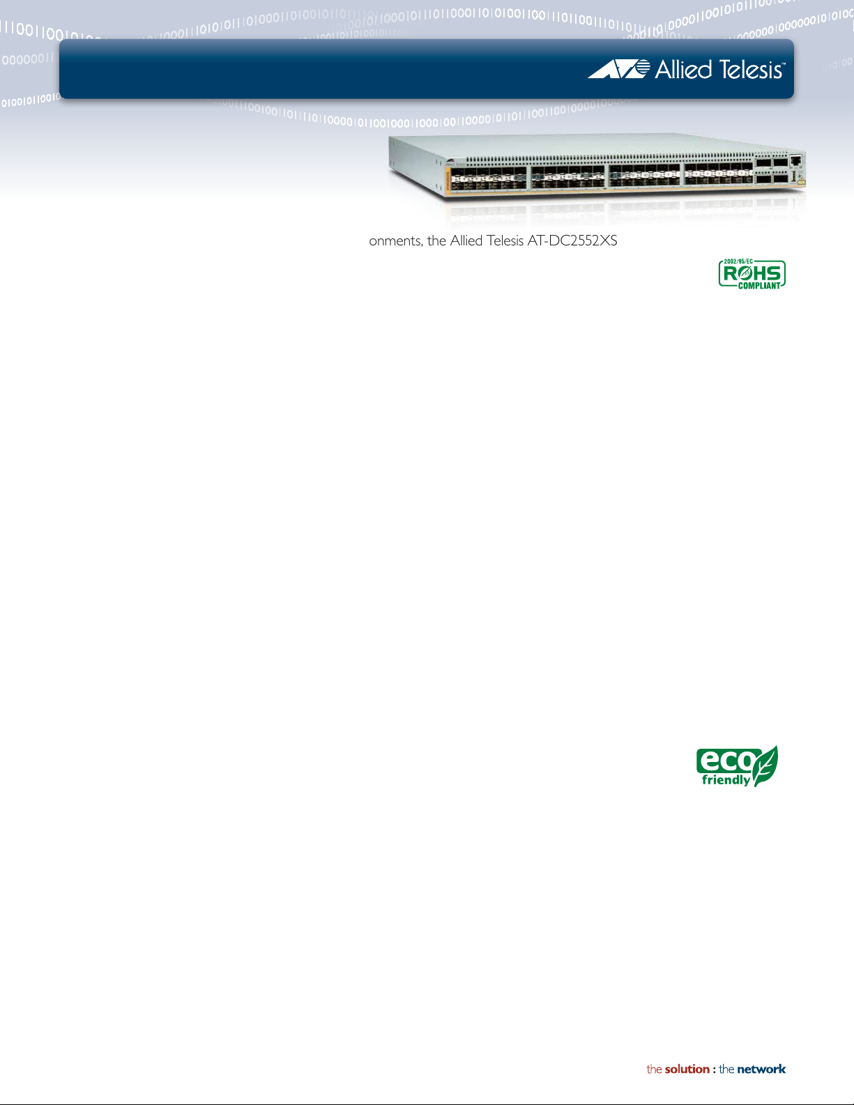
Designed for virtualized data center and cloud environments, the Allied Telesis AT-DC2552XS
switch provides high density 10GbE and 40GbE connectivity, making it ideal for today’s mini and
small data centers, which use up to hundreds of server ports.
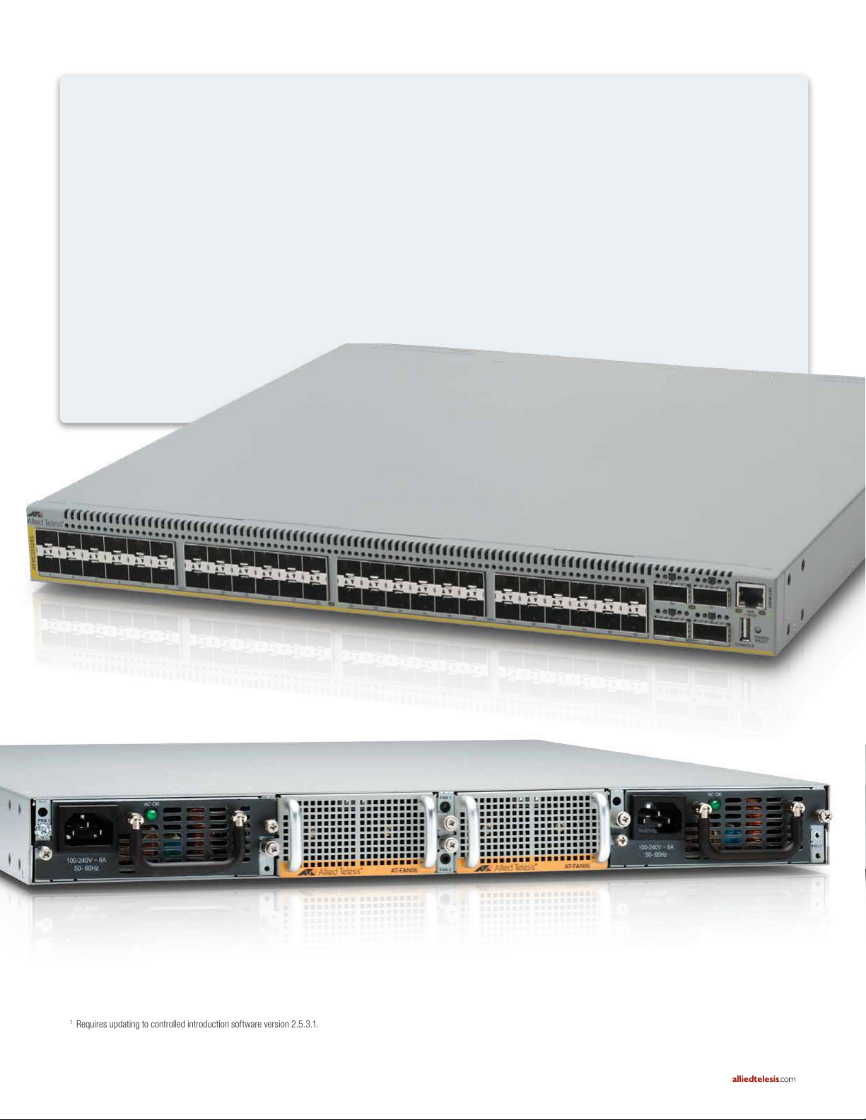
The Allied Telesis AT-DC2552XS is a 48
x 10GbE (SFP+) port high-bandwidth
and high-density switch designed for
data center applications. It also provides
four QSFP+ 40GbE slots for “fat-pipe”
high bandwidth uplinks. This switch
delivers 1280Gbps of switching fabric
with ultra low sub-μsec latency. Airow
has been optimized for front-to-back
cooling for data center environments.
The unit can also accommodate a 1+1
resilient power supply, along with these
specications, in a very compact 1RU
unit chassis.
A smarter data center can be achieved
by connecting servers and storage
facilities with a high-speed and low
latency network fabric that is faster,
greener, open, and easy to manage.
Advanced Energy Efciency
Energy efcient architecture and
front-to-back air-ow cooling of the
AT-DC2552XS are critical factors in
optimizing data center economics—as
companies must balance performance
with power consumption to meet
energy budgets.
High-bandwidth
As bandwidth-intensive applications—
such as Web 2.0, virtualization, HighPerformance Computing (HPC) and
Network Attached Storage (NAS)—
continue to proliferate within enterprise
data centers, 10 Gigabit Ethernet
(10GbE) provides a cost-effective way
to increase throughput and seamlessly
deliver customer Service Level
Agreements.
Future Proong
10GbE empowers companies to
expand application capabilities, reduce
time to solve complex nancial and
scientic applications, and quickly
respond to changing customer needs
and market conditions.
In combination with the AT-VNC10S
Network Interface Cards for servers, it
helps clients to reduce the use of I/O
adapters, reducing costs and complexity.
High Availability
The AT-DC2552XS has two slots for
hot-swappable PSUs (Power Supply
Unit) and fans. In addition, SFP+ and
QSFP modules can be easily removed
and replaced with no interruption to the
network. These hot-swappable modules
guarantee the continued delivery of
essential services.
Cut-through
Cut-through switching sends packets
to their destination as soon as the
rst part is ready. The delay is minimal
and the packet reaches its destination
in the shor test possible time. With
cut-through mode, the AT-DC2552XS
forwards packets with a latency of
505 nanoseconds with 40Gb / 800
nanoseconds with 10Gb and is ideal for
inter-server communication.
Air Flow
Cooling air ow has become a major
design concern in modern data centers.
The AT-DC2552XS utilizes front (PSU
and fan side) to back (ports side) airow,
which is suitable for rack mounting in
data centers.
Eco-friendly
In keeping with our commitment to
environmentally
friendly products, this
switch is designed
to reduce power consumption and
minimize hazardous waste.
alliedtelesis.com
Page 2
AT- DC2552 XS | High Performance, Low Latency Top-of-Rack Data Center Switch
Resilient Ethernet Fabric
Resilient Ethernet Fabric (REF)1 increases availability
using a dedicated bypass link. If one of the links or units
fails, the bypass link restores connectivity. By setting
up the same L ACP trunk group over two AT-DC2552XS
units, REF uses link aggregation to increase throughput
beyond what a single connection could sustain, while
providing link path redundancy.
» Master-less
» Layer 2 mesh on spine-leaf model
» Active-active, multi-path
» Easy setup
Master-less
» There is no “synchronize” process which the hardware
stacking feature usually requires. Instead of setting up
“masters” and “members,” REF recognizes the other
device just as a partner and eliminates the downtime
of master fail-over.
Layer 2 M esh on Spine-Leaf
» One pair of AT-DC2552XS switches with aggregation
mode suppor ts up to five pair of AT-DC2552XS with
ToR mode, which would connect a maximum of 40
servers per rack.
Active-Active, Multi-Path
» While Spanning Tree Protocol requires active-standby
configuration and switchover time for failure, REF
supports active-active configuration, preventing any
perceptible disruption in the case of a link failure.
Even if one of the devices fails, an alternative path
is secured and ensures absolute minimal network
downtime.
Easy Setup
» REF is configured with QSFP modules between two
AT-DC2552XS units, and breakout cables between
the ToR and the aggregation switch.
1
Requires updating to controlled introduction software version 2.5.3.1.
Contact your local Allied Telesis suppor t staf f for details.
2 | AT-DC2552XS
Page 3

AT- DC2552 XS | High Performance, Low Latency Top-of-Rack Data Center Switch
Server
Rack 1
Server
Rack 5
10 Gigabit link
40 Gigabit link
Breakout Cable
40G
10G
10G
10G
10G
52
50
49
51
Ports for Bypass
Ports for Server
52
50
49
51
Ports for ToR
Ports for Bypass
Ports for Core Switch
1 - 40
49, 53 (40G), 57- 64 (10G)
1 - 40
57- 64 (10G)
Ports for Aggregation
49 - 56 (10G)
41 - 43
ToR switch A/B
Up to 10 breakout cables
per aggregation switch
Aggregation switch A/B
REF Port Usage
This network conguration enables server and storage
to communicate within two layers, securing the
low-latency and high-speed connection. The bypass
supports up to 160Gbps for aggregation mode or
80Gbps for ToR mode.
Between Server Racks
■ Two sets of AT-DC2552XS with aggregation mode
can be connected with QSFP direct attach cables.
■ The breakout cable can be connected between
the four 10Gbs ports on the AT-DC2552XS with
aggregation mode, and the QSFP port with ToR
mode.
In the Server Rack
■ Two sets of AT-DC2552XS with ToR mode can be
bypass connected with QSFP direct attach cables.
■ Two ports of 10Gbp on servers/storage can
be connected with the 10Gbps port on ATDC2552XS (TOR-A) and AT-DC2552XS (TOR-B).
AT-DC2552XS | 3
Page 4

AT- DC2552 XS | High Performance, Low Latency Top-of-Rack Data Center Switch
Servers-Storage
DC2552XS
SERVER RACK
DC2552XS
DC2552XS
AoE communication
SBx8100
LAYER 3 FEATURES
x900-24
x900-24
DC2552XS
DC2552XS
DC2552XS
STORAGE RACK
DC2552XS
Specifications
Port
» Switch port
SFP+ slot x 48 ports
QSFP+ slot x 4
» Console port
RS-232 (USB connector) x 1
» Management port
10/100/1000T (RJ-45 connector) x 1
Auto negotiation, MDI-MDI-X
System
» Forwarding rate 952.38Mpps
» Switching capacity 1280Gbps
» 128K MAC addresses
» Cut-through mode
Latency 40GB:505 ns (64 byte)
10GB:800 ns (64 byte)
» 2GB RAM
» 128MB flash memory
» 1.3G hz C PU
» 9MB packet buffer
» Maximum jumbo frames 12Kbytes
» 32 link aggregation group / eight members per group
Wirespeed Switching on all Ethernet ports
» 14,880,000pps for 10Gbps Ethernet
» 59,523,800pps for 40Gbps Ethernet
Environmental Specifications
» Operating temperature 0ºC to 40ºC
» Storage temperature -20ºC to 60ºC
» Operating humidity 10% to 80%
(non-condensing)
» Storage humidity 5% to 90%
(non-condensing)
Port Configuration
» Auto-negotiation, duplex, MDI/MDI-X,
IEEE 802.3x flow control
» Packet storm protection
» Port mirroring
» Broadcast storm control
» Ethernet statistics
» Egress-rate-limit
» LinkTrap
10 Gigabit link
40 Gigabit link
Ethernet Specifications
» IEEE 802.3 10T*
» IEEE 802.3u 100TX*
» IEEE 802.3ab 1000T*
» IEEE 802.3ae 10G-SR, 10G-LR
» IEEE 802.3ba 10G-SR4/XLPPI,40G-CR4
» IEEE 802.1Q Virtual L ANs
» IEEE 802.3ad (L ACP) Link aggregation
» IEEE 802.3z Gigabit Ethernet
2
* Only for management port use
Qual ity of Ser vic e (QoS)
» Head-of-line blocking prevention
» Eight egress queues per port
» IEEE 802.1p Class of Service with strict and weighted
round robin scheduling/strict priority scheduling
» Access Control Lists (ACLs)
» Policy-based QoS
Spanning Tree Protocol
2
» IEEE 802.1D Spanning Tree Protocol
» IEEE 802.1w Rapid Spanning Tree
» IEEE 802.1s Multiple Spanning Tree
4 | AT-DC2552XS
2
Requires updating to controlled introduction software version 2.5.4.1.
3
Requires updating to controlled introduction software version 2.5.3.1.
Contact your local Allied Telesis suppor t staf f for details.
Page 5

AT- DC2552 XS | High Performance, Low Latency Top-of-Rack Data Center Switch
Management
» Enviromental monitoring
» DHCP client
» RFC 1350 TFTP client
» NTP
» Zmodem
» HTTP
» TFTP
» RFC 1157 SNMPv1
» RFC 1901 SNMPv2c
» RFC 2571-5 SNMPv3
» RFC 1757 RMON group 1, 3, 9
» Syslog client support
» Event log
» Telnet
» SSHv2
MIB Support
» RFC 1643 Ethernet-like MIB
» Allied Telesis private MIB
» RFC 1757 RMON MIB
» RFC 1493 Bridge MIB
» RFC 1573/2863 Interfaces group MIB
» RFC 1213 MIB-II
» RFC 1215 TRAP MIB
» RFC 3635 Ethernet MIB
VLAN
» 4094 VLANs
» MAC based VL ANs – 1K
» Port-based VL ANs
» IEEE 802.1Q tag-based VLANs
» Double tag VL AN (Q-in-Q)
4
Security
» Hardware packet filtering
» Layer 2 /3/4 Access Control Lists (ACLs)
» 512 ACL profiles
» 256 rules per ACL profile
» ACLs based on:
- ICMP
- IP
- MAC address
- IP protocol
- TCP
- UDP
» DoS attack protection
- Smurf
- SYN flood
- Teardrop
- Land
- IP option
- Ping attack
Compliance Standards
» IEEE 802.3ae, 10G SFP+ - SFP+ fiber, SFP+ direct
attach
» IEEE 802.3ba - QSFP+
Safety and Electromagnetic Emissions
Certifications
» EMI: FCC class A, CISPR class A, EN55022 class A
» C-TICK, VCCI Class A, CE
» Immunity: EN50024, EN601000-3-3,
EN601000-3-2
» Safety: UL 60950-1 (cUlus), EN60950-1 (TUV)
Physical Specifications
Dimensions 44.1 cm x 46 cm x 4.4 cm
(W x D x H) 17.4 in x 18.1 in x 1.7 in
Weight 8.3 kg /18.3 lb (chassis only)
11.3 kg/24.9 lb (chassis with
two fans and two PSUs)
Power Characteristics
» Voltage: 100-240V AC (10% auto-ranging)
» Frequency: 50/60 Hz
» Maximum current: 14A @ 100V
» Heat dissipation: 900 BTU/hr
Power Consumption
» 250W (max 280W )
Link Aggregation
» Static trunking
» IEEE 802.3ad LACP
» IP option
» Dynamic LACP
» Port trunking
IP Multicasting
» RFC 1112 IGMPv1 snooping
» RFC 2236 IGMPv2 snooping
» RFC 3376 IGMPv3 snooping
» Multicast groups - 255
4
Requires updating to controlled introduction software version 2.5.3.1.
Contact your local Allied Telesis suppor t staf f for details.
Physical Specifications
Compliant with European RoHS standards
Package Specifications
» AT-DC2552XX switch with two PSU bay covers and
two FAN unit bay covers
» Management cable (RS-232 to USB)
» Rubber feet and 19 in rack-mountable hardware kit
accessories
» Install guide and CLI users guide available at
alliedtelesis.com/support
AT-DC2552XS | 5
Page 6

AT- DC2552 XS | High Performance, Low Latency Top-of-Rack Data Center Switch
Ordering Information
AT-DC2552XS
48-port SFP+ slot
4-port QSFP slot
1-port console port
1-port management port
2 slots for PSUs
2 slots for fans
SFP+ Modules
AT-S P10S R
10G-S R
AT-SP10LR
10G-LR
AT-PWR06-xx
Hot-swappable AC power supply
AT- FA N 06
Hot-swappable fan
(Two fans are needed to operate. Reverse cooling
airflow — port side to PSU/fan side —
is not supported)
Where xx =
10 for US power cord
30 for U K power cord
40 for A ustralian power cord
50 for European power cord
QSFP+ and Cable
AT- Q S F P1CU
QSFP+copper cable 1 m
AT- Q S F P3CU
QSFP+ copper cable 3 m
AT-QSFPSR
QSFP+ module
Optical Cables
AT-MTP12-1
MTP cable for AT-QSFP SR, 1 m
AT-S P10T W1
10G SFP+ direct attach cable (1 m)
AT-S P10T W3
10G SFP+ direct attach cable (3 m)
AT-SP10TW7
10G SFP+ direct attach cable (7 m)
SFP Modules
6
AT-S P L X10
1000LX
AT-S P S X
1000SX
AT-MTP12-5
MTP cable for AT-QSFP SR, 5 m
Breakout Cables
5
AT-QSFP-4SFP10G-3CU
QSFP to 4 x SFP+ breakout direct at tach cable (3 m)
AT-QSFP-4SFP10G-5CU
QSFP to 4 x SFP+ breakout direct at tach cable (5 m)
5
Requires updating to controlled introduction software version 2.5.3.1.
Contact your local Allied Telesis suppor t staf f for details.
6
Requires updating to controlled introduction software version 2.5.4.1.
Contact your local Allied Telesis suppor t staf f for details.
North America Headquarters | 19800 Nor th Creek Parkway | Suite 100 | Bothell | WA 98011 | USA | T: +1 800 424 4284 | F: +1 425 481 3895
Asia-Pacic Headquarters | 11 Tai Seng Link | Singapore | 534182 | T: +65 6383 3832 | F: +65 6383 3830
EMEA & CSA Operations | Incheonweg 7 | 1437 EK Rozenburg | The Netherlands | T: +31 20 7950020 | F: +31 20 7950021
alliedtelesis.com
© 2013 Allied Telesi s, Inc. All ri ghts reser ved. Infor mation in thi s document is su bject to chan ge without no tice. All comp any names, log os, and produ ct designs t hat are trad emarks or r egistere d trademar ks are the pr operty o f their respe ctive owner s.
617-00453 Re v. E
 Loading...