

Page 1

Cable/DSL
Router
AT-AR221E
Installation Guide
PN D617-90000 Rev 1
Page 2

Copyright. 2003 Allied Telesyn,Inc.
960 Stewart Drive Suite B, Sunnyvale, CA 94085 USA
All rights reserved. No part of this publication may be reproduced without prior written permission from Allied Telesyn,
Inc.All product names, company names,logos or other designations mentioned herein are trademarks or registered trademarks of their respective owners.Allied Telesyn, Inc. reserves the right to make changes in specifications and other information contained in this document without prior written notice
.
The inf
ormation pr
o
vided her
ein is subject to change
without notice. In no event shall Allied Telesyn, Inc. be liable for any incidental,special, indirect, or consequential damages
whatsoever, including but not limited to lost profits, arising out of or related to this manual or the information contained
herein, even if Allied Telesyn, Inc. has been advised of,known, or should have known, the possibility of such damages.
Page 3

Electrical Safety and Emission Statement
Standards:This product meets the following standards.
U
.S. Federal Communications Commission
This de
vice complies with Part 15 of the FCC Rules. Operation is subject to the following two conditions:
This de
vice may not cause harmful interference.
This device must accept any interference received, including interference that may cause undesired operation.
Note:
This equipment has been tested and found to comply with the limits for a Class B digital device, pursuant to part
15 of the FCC Rules.These limits are designed to provide reasonable protection against harmful interference in a residential installation.This equipment generates, uses,and can radiate radio frequency energy and, if not installed and used in
accordance with the instructions, may cause harmful interference to radio communications. However, there is no guarantee that interference will not occur in a particular installation. If this equipment does cause harmful interference to radio
or television reception, which can be determined by turning the equipment off and on, the user is encouraged to try to
correct the interference by one or more of the following measures:
- Reorient or relocate the receiving antenna.
- Increase the separation between the equipment and receiver.
- Connect the equipment into an outlet on a circuit different from that to which the receiver is connected.
- Consult the dealer or an experienced radio/TV technician for help.
Canadian Department of Communications
This Class B digital apparatus meets all requirements of the Canadian Interference-Causing Equipment Regulations.
Cet appareil numérique de la classe B respecte toutes les exigences du Règlement sur le matériel brouilleur du Canada.
CE Marking Warning:This is a Class B product. In a domestic environment this product may cause radio interference
in which case the user may be required to take adequate measures.
Important:Appendix A contains translated safety statements for installing this equipment.When you see the
go to Appendix A for the translated safety statement in your language.
Wichtig:Anhang A enthält übersetzte Sicherheitshinweise für die Installation dieses Geräts.Wenn Sie
sehen, schlagen Sie in Anhang A den übersetzten Sicherheitshinweis in Ihrer Sprache nach.
Vigtigt:Tillæg A indeholder oversatte sikkerhedsadvarsler, der vedrører installation af dette udstyr. Når De ser symbolet
, skal De slå op i tillæg A og finde de oversatte sikkerhedsadvarsler i Deres eget sprog.
Belangrijk:Appendix A bevat vertaalde veiligheidsopmerkingen voor het installeren van deze apparatuur.Wanneer u de
ziet, raadpleeg Appendix A voor vertaalde veiligheidsinstructies in uw taal.
Important : L'annexe A contient les instructions de sécurité relatives à l'installation de cet équipement. Lorsque vous
voyez le symbole ,reportez-vous à l'annexe A pour consulter la traduction de ces instructions dans votre langue.
Tärkeää: Liite A sisältää tämän laitteen asentamiseen liittyvät käännetyt turvaohjeet. Kun näet -symbolin, katso
käännettyä turvaohjetta liitteestä A.
Importante: l’Appendice A contiene avvisi di sicurezza tradotti per l’installazione di questa apparecchiatura. Il simbolo
,indica di consultare l’Appendice A per l’avviso di sicurezza nella propria lingua.
Viktig:Tillegg A inneholder oversatt sikkerhetsinformasjon for installering av dette utstyret. Når du ser , åpner du
til Tillegg A for å finne den oversatte sikkerhetsinformasjonen på ønsket språk.
Importante: O Anexo A contém advertências de segurança traduzidas para instalar este equipamento.Quando vir o símbolo , leia a advertência de segurança traduzida no seu idioma no Anexo A.
Importante: El Apéndice A contiene mensajes de seguridad traducidos para la instalación de este equipo.Cuando vea el
símbolo , vaya al Apéndice A para ver el mensaje de seguridad traducido a su idioma.
Obs! Bilaga A innehåller översatta säkerhetsmeddelanden avseende installationen av denna utrustning. När du ser ,
skall du gå till Bilaga A för att läsa det översatta säkerhetsmeddelandet på ditt språk.
Page 4

Table of Contents
Electrical Saf
ety and Emission Statement ..................................................................................................................... 1
Preface ............................................................................................................................................................................... 4
Purpose of This Guide ...................................................................................................................................................... 4
Ho
w This Guide is Organized.......................................................................................................................................... 4
Document Conventions.................................................................................................................................................... 5
Where to Find Related Guides ...................................................................................................................................... 6
Contacting Allied Telesyn Technical Support ............................................................................................................... 6
Returning Products ........................................................................................................................................................... 8
FTP Ser
ver ........................................................................................................................................................................... 8
F
or Sales or Corporate Information ............................................................................................................................. 8
Tell Us What You Think .................................................................................................................................................... 14
Chapter 1
Introduction
..................................................................................................................................................................... 15
Router Features ................................................................................................................................................................. 15
Package Contents .............................................................................................................................................................. 17
Chapter 2
Installation
........................................................................................................................................................................ 18
Installing the Hardware .................................................................................................................................................... 18
Reviewing Safety Precautions ......................................................................................................................................... 18
Powering the Device ........................................................................................................................................................ 19
POST (Power-On-Self-Test) ............................................................................................................................................ 19
Connecting the Router to Computers and Network............................................................................................... 19
Modem Connection .......................................................................................................................................................... 19
Setting Up a Client Computer ....................................................................................................................................... 21
Setting Up the Router........................................................................................................................................................ 21
Chapter 3
Configuration Wizard
................................................................................................................................................. 22
Web Interface ..................................................................................................................................................................... 22
PPPoE..................................................................................................................................................................................... 23
Dynamic IP............................................................................................................................................................................ 24
Dynamic IP (Road Runner) ............................................................................................................................................. 25
Static (Fixed) IP.................................................................................................................................................................... 26
PPTP........................................................................................................................................................................................ 27
Chapter 4
Basic Settings
................................................................................................................................................................... 28
PPPoE..................................................................................................................................................................................... 29
Dynamic IP............................................................................................................................................................................ 30
Dynamic IP (Road Runner) ............................................................................................................................................. 31
Static (Fixed) IP.................................................................................................................................................................... 32
PPTP........................................................................................................................................................................................ 33
DHCP Server....................................................................................................................................................................... 34
Change Password................................................................................................................................................................ 35
2
Page 5

Cha
pter 5
Advanced Configuration
.......................................................................................................................................... 36
Vir
tual Server...................................................................................................................................................................... 36
Special Applications............................................................................................................................................................ 37
DMZ and FTP (Miscellaneous Items)..........................................................................................................................., 38
Pack
et Filters....................................................................................................................................................................... 39
Domain Filters....................................................................................................................................................................
40
URL Blocking....................................................................................................................................................................... 41
MA
C Control...................................................................................................................................................................... 42
Remote
Administrator (Miscellaneous) ....................................................................................................................... 43
System
Time........................................................................................................................................................................ 44
System Log ......................................................................................................................................................................... 45
Dynamic DNS .................................................................................................................................................................... 46
SNMP ....................................................... ........................................................................................................................... 47
Routing ................................................................................................................................................................................ 48
Schedule Rule .................................................................................................................................................................... 49
View Log ............................................................................................................................................................................. 50
Firmware Upgrade ............................................................................................................................................................ 51
Backup Settings ................................................................................................................................................................. 52
Reset to Defaults .............................................................................................................................................................. 52
Reboot ................................................................................................................................................................................. 52
Wake-on-LAN (Miscellaneous)....................................................................................................................................... 53
Chaper 6
System Status and Help
............................................................................................................................................. 54
System Status...................................................................................................................................................................... 54
Help....................................................................................................................................................................................... 54
Chapter 7
Setting Up Client Computers for Internet Access
..................................................................................... 55
Client Computer Requirements ................................................................................................................................... 55
Setting up Windows 95/98 PC Clients ........................................................................................................................ 55
Configuring a Client Computer Using the DHCP Server ...................................................................................... 56
Configuring a Client Computer Manually ................................................................................................................... 56
Setting Up Windows NT 4.0 Clients ........................................................................................................................... 56
Configuring a Client Computer Using the DHCP Server ...................................................................................... 56
Configuring a Client Computer Manually ................................................................................................................... 58
Chapter 8
Troubleshooting
............................................................................................................................................................ 60
Power LED OFF ................................................................................................................................................................ 60
Status LED Never Blinks or LED Stays ON .............................................................................................................. 60
Testing the LAN Path to Your Router ......................................................................................................................... 60
Testing the LAN Path from your PC to a Remote Device .................................................................................... 60
Appendix A
Specifications
................................................................................................................................................................. 62
Appendix B
Translated Electrical Safety and Emission Information
........................................................................... 67
3
Page 6

Preface
Purpose of This Guide
This guide is intended f
or network administrators who are responsible for installing and maintaining the AT-AR221E
Cable/DSL Router
.
How This Guide is Organized
This guide contains the following chapters and appendices:
Chapter 1,
Introduction, describes the features, functions,LEDs, and ports on the router.
Chapter 2, Installation, describes how to install the router.
Chapter 3,
Configuration Wizard, describes the procedures for accessing the router through its Web interface and for
quickly configuring the router.
Chapter 4,
Basic Settings, describes the procedures for manually configuring the basic parameters.
Chapter 5,Advanced Configuration, describes the procedures for entering configurations on advanced router features.
Chapter 6,
System Status and Help describes the procedures for getting on-line help with the router.
Chapter 7, Setting Up Client Computers for Internet Access, describes the procedures for configuring a Windows
client.
Chapter 8,
Troubleshooting,describes procedures for resolving error conditions on the router.
Appendix A, Specifications, provides router specifications.
Appendix B,
Translated Electrical Safety and Emission Information, contains multi-language translations of the
cautions and warnings in this manual.
4
Page 7

Document Conventions
This guide uses se
veral conventions that you should become familiar with before you begin to install the product:
Note
A note provides additional information.
Warning
A warning indicates that performing or omitting a specific action may result in bodily injury.
Caution
A caution indicates that performing or omitting a specific action may result in equipment damage
or loss of data.
5
Page 8

Where to Find Related Guides
The
Allied Telesyn web site at
www
.alliedtelesyn.com
under the suppor
t section contains the most recent documen-
tation f
or all of our products. All web-based documents relating to this product and other Allied Telesyn products can be
downloaded from the web site.
Contacting Allied Telesyn Technical Support
You can contact Allied Telesyn technical support through the company’s web site www.alliedtelesyn.com under the
support section or by telephone or fax.
Telephone and Fax Support
EUROPEAN SUPPORT NUMBERS
Telephone support is available Monday through Friday between 0900 and 1730 local time (excluding national holidays).
Austria, Belgium, Finland,France,Germany,Ireland, Italy,Luxembourg,The Netherlands, Norway,Sweden,
Switzerland and the United Kingdom
Free phone 00 800 287 877 678 or +31 20 711 4333
europe_support@alliedtelesyn.com
Spain:
Free phone 00 800 287 877 67 or +31 20 711 4333
europe_support@alliedtelesyn.com
Finland:
Free phone: 990 800 287 877 67 or +31 20 711 4333
europe_support@alliedtelesyn.com
Croatia and Slovenia:
Support Telephone number: +385 1 382 1341
Support Fax Number: + 385 1 382 1340
Support Email Address:ATIhelpdesk_Croatia@alliedtelesyn.com
Czech Republic:
Support Telephone number: +420 296 538 888
Support Fax Number: +420 296 538 889
Support Email Address: Czech_suppor
t@alliedtelesyn.com
6
Page 9

Hungar
y:
Suppor
t Telephone number: +36 1 382 6385
Suppor
t Fax number: +36 1 382 6398
Support Email Address: Hungary_Helpdesk@alliedtelesyn.com
Poland:
Suppor
t Telephone number: +48 22 535 9670
Suppor
t Fax number: +48 22 535 9671
Suppor
t Email Address: Polska_pomoc@alliedtelesyn.com
Serbia, Montenegro, Macedonia,Bosnia and Herzegovina and Bulgaria:
Support Telephone number: +381 11 32 35 639
Support Fax Number: +381 11 3235 992
Support Email Address:Yug.Servis@alliedtelesyn.com
Russia and former Soviet Union Countries:
Support Telephone number: +7-095-935 8585
Support Fax Number: +7-095-935 8586
Support Email Address : support_CIS@alliedtelesyn.ru
Ukraine:
Support Telephone number: +7-095-935 8585
Support Fax Number: +7-095-935 8586
Support Email Address : Ukraine support@alliedtelesyn.com
All other countries not listed above should refer their technical support request to:
Support Telephone number: +31 20 711 4333
Support Email Address: europe_support@alliedtelesyn.com
Americas:
Technical Support by Phone or Fax (8-5 PST M-F)
Toll-free: 1 800 428 4835
Fax: 1 425 481 3790
*Support for Puerto Rico and the US Virgin Islands is provided through our Technical Support Center in Latin America.
México
Email soporte_mexico@alliedtelesyn.com
Teléfono +52 55 5559 0611
7
Page 10

Returning Products
Pr
oducts for return or repair must first be assigned a Return Materials Authorization (RMA) number. RMA policy varies
fr
om country to country. Please check the applicable RMA policy at www.alliedtelesyn.com For Europe,you can also con-
tact our European Customer Service centre by email at
rma_europe@alliedtelesyn.com.
FTP Server
If you need management software for an Allied Telesyn managed device, you can download the software by connecting
dir
ectly to our FTP server at
ftp
.alliedtelesyn.com.
At login,
enter “anonymous” as the user name and your e-mail
address as the password.
For Sales or Corporate Information
European & Latin America Headquarters
Allied Telesis International SA
Via Motta 24
6830 Chiasso
Switzerland
Tel: +41 91 6976900
Fax: +41 91 6976911
Allied Telesis International Services
Piazza Tirana n.24/4 B
20147 Milano
Italy
Tel: +39 02 4141121
Fax: +39 02 41411261
REGIONAL LOCATIONS
Austria & Eastern Europe
Allied Telesyn Vertriebsgesellschaft m.b.H.
Lainzer Strasse 16/5-6
1130,Vienna
Tel: +43-1-876 24 41
Fax: +43-1-876 25 72
8
Page 11

P
oland
Allied
Telesyn Vertriebsgesellschaft m.b.H.
Sp
. z o.o. Oddzial w Polsce
ul. Elektoralna 13
00-137
Warszawa
Tel: +48 22 620 82 96
Fax:
+48 22 654 48 56
Romania
Allied Telesyn Vertriebsgesellschaft m.b.H.
str.Thomas Masaryk 23
Sector 2, Bucharest 0209
Tel: +40-21-211-1817/8245
Fax: +40-21-210-5610
Russia
Allied Telesyn International
Ul. Korovij Vall
Dom 7 Str. 1 Office 190
119049 Moscow
Tel: +7095 9358585
Fax: +7095 9358586
Serbia & Montenegro
Allied Telesyn Vertriebsgesellschaft m.b.H.
Krunska 6
11000 Belgrade
Tel & Fax: +381 11 3033 208
+381 11 3033 209
+381 11 3235 639
France
Allied Telesyn International SAS
12, avenue de Scandinavie
Parc Victoria, Immeuble “Le Toronto”
91953 Courtaboeuf Cédex - Les Ulis
Tel: +33 1 60 92 15 25
Fax: +33 1 69 28 37 49
9
Page 12

Gr
eece
Allied
Telesyn International S.r.l
Kiriazi 14-16
145 62 Kifisia
T
el: +30 210 6234 200
Fax: +30 210 6234 209
Ital
y – North
Allied
Telesyn International S.r.l.
Via Anna Kuliscioff, 37
20152 Milano
Tel: +39 02 41304.1
Fax: +39 02 41304.200
Italy – East
Tel: +39 348 1522583
Tel & Fax: +39 049 8868175
Italy – South
Allied Telesyn International S.r.l.
Via Troilo il Grande 3
00131 Roma
Tel: +39 06 41294507
Fax: +39 06 41404801
Turkey
Allied Telesyn International
6. Cadde 61/2 Öveçler
06460 Ankara
Tel: +90 312 472 1054/55
Fax: +90 312 472 1056
Germany – North
Allied Telesyn International GmbH
Kapweg 4
13405 Berlin
Tel: +49-30-435 900-0
Fax: +49-30-435 900-300
Toll Free (Sales): 00 800 255 43310
Toll Free (Technical Support): 00 800 287 877678
10
Page 13

German
y – South
Allied
Telesyn International GmbH
Zeppelinstr
.1
85399 Hallbergmoos
T
el: +49-811-999 37-0
Fax: +49-811-999 37-22
Belgium & Lux
embourg
Allied
Telesyn International
Research Park
Kranenberg 6, 1731 Zellik, Belgium
Tel: +32 2 481 60 68
Fax: +32 2 481 60 75
Denmark
Allied Telesyn International
Jyllinge ErhvervsCenter
Møllehaven 8
DK-4040 Jyllinge
Tel: +45 46734835
Fax: +45 46734837
Finland
Allied Telesyn International Ltd.
Metsänneidonkuja 10
02130 ESPOO
Tel: +358 9 7255 5290
Fax: +358 9 7255 5299
Iceland +47 22 70 04 70
Ireland (Freephone) 1 800 409 127
The Netherlands
Allied Telesyn International BV
Hoeksteen 26
2132 MS Hoofddorp
Tel: +31 20 6540 246
Fax: +31 20 6540 249
11
Page 14

Norwa
y
Allied
Telesyn International
Ole De
viksvei 4
0666 Oslo
T
el: +47 22 70 04 70
Fax: +47 22 70 04 01
Sw
eden
Allied
Telesyn International
Byängsgränd 14
120 40 Årsta
Tel: +46 8 13 14 14
Fax: +46 8 681 04 45
United Kingdom
Allied Telesyn International Ltd.
100 Longwater Avenue
GreenPark
Reading, RG2 6GP
Tel: +44 118 920 9800
Fax: +44 118 975 2456
Latin America - Support Office
Allied Telesyn International
19800 North Creek Parkway, Suite 200
Bothell,WA 98011 USA
Tel: +1 425 481 3852
Fax: +1 425 489 9191
Toll Free (Mexico & Puerto Rico): (95-800) 424 5012 ext. 3852
Latin America – Mexico
Allied Telesyn International
AV. Insurgentes Sur # 800,Piso 8
Col. Del Valle
México, DF,03100
Tel: +52 55 5448 4989
Fax: +52 55 5448 4910
12
Page 15

P
ortugal
Allied
Telesyn International
Centr
o de Escritórios das Laranjeiras
Praça Nuno Rodrigues dos Santos, Nº 7 Sala 211
1600-171 Lisbon
Tel: +351 21 721 74 00
Fax:
+351 21 727 91 26
Spain
Allied Telesyn International S.L.U
Plaza de España
18-4ª Ofic. 3,28008 Madrid
Tel: +34 91 559 1055
Fax: +34 91 559 2644
Allied Telesyn International, Corp.
19800 North Creek Parkway, Suite 200
Bothell,WA 98011
Tel: 1 (425) 487-8880
Fax: 1 (425) 489-9191
Allied Telesyn International, Corp.
960 Stewart Drive, Suite B
Sunnyvale, CA 94085
Tel: 1 (800) 424-4284 (USA and Canada)
Fax: 1 (408) 736-0100
For current information, please visit our web site :
www.alliedtelesyn.com
13
Page 16

Tell Us What You Think
If y
ou have any comments or suggestions on how we might improve this or other Allied Telesyn documents, please
contact us at
www
.alliedtelesyn.com.
14
Page 17

Chapter 1
Introduction
Thank you for purchasing the AT-AR221E Cable/DSL Router with an integral 4- port switch.This easy-to-use router offers
small offices and home offices an economical wa
y to connect their entire LAN to the Internet using an external DSL/Cable
modem.
Router Features
l High speed Internet access - Includes a WAN port for connection to an external DSL/Cable modem for high speed
Internet access (20~200 times faster than your legacy 56K modem)
l Built-in four-port 10/100 Mbps Ethernet Switch - Provides complete and fast connectivity for small offices.
l Shared single ISP account - Provides an affordable Internet access for all the computers in your office using a single ISP
account, via Network Address Translation (NAT). NAT is always enabled.
l DHCP (Dynamic Host Configuration Protocol) - Simplifies setup and management of all you network resources.
l PPPoE & PPTP - Allows for flexible use and configuration of ADSL.
l Stateful Inspection Firewall – To protect your computer data against un-authorised access via the Internet.
l Web-based management - Includes an intuitive web-based configuration and administration interface to simplify router
management.
l SNMP based management – Allows the router to be managed as part of a large corporate network.
l DNS Server - Supports two DNS servers that relay DNS entries to speed up the Internet connection.
l Virtual Server - Allows for a Virtual Server configuration (for example, an FTP Server) to allow remote access by out-
side users.
l Access control (packet filtering) - Monitors and blocks specific packets or applications.
15
Page 18

This illustration figur
e 1,shows the front and rear panels of the router.
Figure 1. Router front and rear panels.
LED Colour Function/Description
Power Green Steady on when power is on.
Status Orange Flashing in normal operation
WAN (WAN port)
Link/Act Green Steady on when ADSL/Cable modem is properly connected
Flashing when WAN port has data traffic
100M Green Steady on when WAN port connected at 100Mbps
Off – when WAN port connected at 10Mbps
LAN (1-4 LAN ports)
Link/Act Green Steady on when LAN port is properly connected
Flashing when LAN port has data traffic
100M Green Steady on when LAN port connected at 100Mbps
Off – when LAN port connected at 10Mbps
Init. Press and hold the Initialize button.The Status LED will stop flashing, and then flash 6 times. Then
release the button.
WAN. This port is for connecting to the Wide Area Network using an ADSL or Cable Modem.
LAN 1- 4. These ports are used to connect computers and peripherals to the router.
Power. This sock
et is used to connect the external po
w
er suppl
y to the r
outer
.
WAN
1
POWER
SPEED
LINK
STA
TUS
4
3
2
1
2
34 WA N
Init
Power
16
Page 19

Package Contents
Check y
our router package for the following items.If an item is missing or damaged, contact your Allied Telesyn sales rep-
r
esentative for assistance.
Figure 2. Package contents.
l 1 x Broadband Router
l 1 x AC/DC power adapter
l 1 x Ethernet Cable
l 1 x This installation guide
17
Page 20

Chapter 2
Installation
Installing the Hardware
Perform the following procedures to install the router.
Reviewing Safety Precautions
Please review the following safety precautions before you begin to install the device in your network. Refer to Appendix
B f
or translated safety statements in your language.
Warning
Lightning Danger: Do not work on this equipment or cables during periods of lightning activity.
1
Warning
Power cord is used as a disconnection device:To de-energize equipment, disconnect the
power cord. 2
Warning
Electrical-Type Class 1 Equipment: This equipment must be earthed.The power plug must be
connected to a properly wired earth ground socket outlet.An improperly wired socket outlet could
place hazardous voltages on accessible metal parts. 3
Caution
Pluggable Equipment:The socket outlet should be installed near the equipment and should be
easily accessible. 4
Caution
Air vents:The air vents must not be blocked on the unit and must have free access to the room
ambient air for cooling. 5
Caution
Operating Temperature:This product is designed for a maximum ambient temperature of 40°C.
6
Caution
All Countries:
Install this product in accordance with local and National Electric Codes. 7
18
Page 21
Powering the Device
1.
Plug the power adapter to an AC power outlet.
2. Connect the output of the power supply to the power connector on the rear of the device.
The Power LED turns on immediately. The device then immediately runs a series of hardware diagnostics to ensure that
the unit can operate pr
operly.
POST (Power-On-Self-Test)
This series of hardware diagnostics is called Power-On-Self-Test (POST).
While the POST is running, watch the front panel of the router. 100M and Link/Act LEDs flash in sequence. If the POST
succeeds without encountering any problems, the 100M and Link/Act LEDs turn OFF.
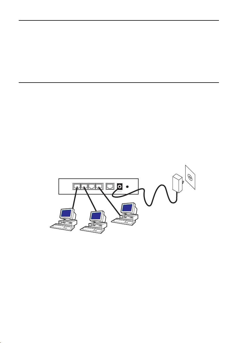
Connecting the Router to Computers and a Network
The device features a built-in 4-port 10M/100M Ethernet switch. Any of the Ethernet ports can be connected to a
computer that has an Ethernet card or NIC (Network Interface Card).
Figure 3. Connecting computers to the router
Modem Connection
The device has one WAN port that connects to an external DSL/Cable modem for Internet access.The following hardware items are needed for the modem connection:
l An external DSL/Cable modem with and Ethernet RJ-45 connector.
l An RJ-45 to RJ-45 cable for connecting the modem to the router.
19
1
2
34 WAN
Init
Power
Page 22

Figur
e 4
illustrates a typical netw
ork topology using the router.
Figure 4. Network Topology Example
1
2
34 WAN
Init
Power
Power
1
2
Link/Act
1000M
100M
3
4
56789101112
1314 1516 17 18 1920
212223
24
DSL/Cable Modem
20
Page 23

Setting Up a Client Computer
T
o access the router’s Web-based management interface, you need a computer that supports the TCP/IP protocol and has
a
Web browser.
This workstation must be in the same subnet as the router.
The default IP ad
dress of the router is
192.168.123.254.
The default network mask is 255.255.255.0.
The router features a standalone DHCP server feature that can configure a client workstation’s TCP/IP setting automatically. Alternatively,you can manually configure the client workstation’s TCP/IP settings as follows:
IP address of
192.168.123.1
Network mask of 255.255.255.0
The router’s IP address as the client workstation’s DNS (Domain Name System) device.
The router’s IP address as the client workstation’s default gateway.
For detailed information on the DHCP server feature, refer to Chapter 4.
Setting Up the Router
To establish an Internet connection to your ISP (Internet Service Provider) via a DSL/Cable modem, set up the modem
and the ISP information on the router. Use a Web browser from a management station to open the Quick Setup interface.This procedure is described in Chapters 3 & 4.
21
Page 24

Chapter 3
Configuration Wizard
The router features a Web-based management wizard.This allows the router to be quickly and easily programmed.
Web Interface
Note
The Web browser software (Netscape Communicator and Microsoft Internet Explorer) are included in the CD shipped
with the router. The browsers can also be downloaded from Netscape Communications’ web site at
<http://www.netscape.com> and Microsoft’s web site at <http://www.microsoft.com>.
The router is pre-configured from the factory with the default IP address
192.168.123.254.
1. Start your web browser on a workstation that has the TCP/IP protocol. (The workstation and the router must
be on the same IP subnet.)
2. Type the router’s IP address in the URL field. For example:http://192.168.123.254 and press Enter.
The router’s default IP address
192.168.123.254. If the IP address of the router has been changed, then enter the cur-
rent one.
The Login window shown in Figure 5 is displayed.
Figure 5. Login Window
3. Do not type anything into the Password field and click OK.
Note
The router is factory-configured with the default password left blank.The Introduction page is displayed. You can start
configuring the router.
4. Click the Wizard item in the left-side window to start the utility.
22
Page 25

PPPoE
This is a
‘dial-up type’ connection type provided by some ISPs. Note that if you select the PPPoE option, then please
remove any existing PPPoE application on all PCs attached to the LAN.
Figure 6. PPPoE Wizard
LAN IP Address: Enter the IP address of the Router (default = 192.168.123.254)
Account: Enter your User Name provided by your ISP. Leave this blank if you have not been given a User Name by your
ISP.
Password: Enter your Password provided by your ISP.
Specify DNS Server Address: Your ISP will provide you with at least one DNS IP Address. Multiple DNS IP settings
are common.The first available DNS entry is used in most cases.
23
Page 26

Dynamic IP (DHCP obtain IP automatically
This is the default option f
or the Router. If your ISP automatically assigned the IP addresses and other values to the Router,
leave it there without making any change.
Figure 7. Dynamic IP Wizard
LAN IP Address: Enter the IP address of the Router (default = 192.168.123.254)
Host Name: This entry is required by certain ISPs. Leave this blank if you have not been given this parameter by your
ISP.
WAN’s MAC Address: This is the MAC address of the Router. Clicking on Clone MAC will program the WAN port of
the router with the MAC address of your PC.
24
Page 27

Dynamic IP Address (Road Runner)
Figure 8. Dynamic IP (Road Runner) Wizard
LAN IP Address: Enter the IP address of the Router (default = 192.168.123.254)
Account: Enter your User Name provided by your ISP. Leave this blank if you have not been given a User Name by your
ISP.
Password: Enter your Password provided by your ISP.
Login Server: Enter the Server Address provided by your ISP.
25
Page 28

Fixed (Static) IP
The Public IP
Address and Subnet Mask of the Router are used by external users of the Internet (including your ISP). If
you have been assigned a Fixed IP address by your ISP, select this item and enter the IP Address and Subnet Mask
pr
ovided.
Figure 9. Fixed (Static) IP Wizard
Specify WAN IP Address: Enter the IP address provided by your ISP.
Subnet Mask: Enter the Subnet Mask values provided by your ISP.
Default Gateway IP Address: Your ISP will provide you with the Default Gateway IP Address.This is sometimes called
the ‘Next-hop’.
Domain Name Server (DNS): Your ISP will provide you with at least one DNS IP Address. Multiple DNS IP settings
are common.The first available DNS entry is used in most cases.
26
Page 29

PPTP
This is a
‘dial-up type’ connection type provided by some ISPs.
Figure 10. PPTPWizard
LAN IP Address: Enter the IP address of the Router (default = 192.168.123.254)
My IP Address: The IP address of the PPTP Client you want to negotiate with the PPTP server
My Subnet Mask: The subnet mask of the PPTP Client
Server IP Address: The address of the PPTP Server
PPTP Account: The login name on the PPTP Server
PPTP Password: The password of the user account
27
Page 30

Chapter 4
Basic Settings
This chapter explains how to use the Basic Setting utility to configure the Internet access settings of the router.
To use the Basic Setting utility:
1. Launch your browser and enter the router’s IP address in the URL field using the following format:
http://192.168.123.254
The IP address shown is the default IP address of your router.
Note
The router is pre-configured at the factory with a default IP address of 192.168.123.254.If this IP address is already being
used by another device on your network,you must turn off the other network device until you have assigned the router
a new IP address.
The first Web page you see is the Login screen, as shown in Figure 11.
Figure 11. Login Screen.
2. Enter the administrator’
s pass
w
or
d (the default has no password set.).
3. Click the
Basic Settings item in the left-side windo
w to start the utility.
28
Page 31

PPPoE
Select Primar
y Settingsfrom under the
Basic Settings, and select PPPoEas the
WAN type.
Figure 12. PPPoE Setup
LAN IP Address: Enter the IP address of the Router (default = 192.168.123.254)
PPPoE Account: Enter your User Name provided by your ISP. Leave this blank if you have not been given a User Name
by your ISP.
Password: Enter your Password provided by your ISP.
Specify DNS Server Address: Your ISP will provide you with at least one DNS IP Address. Multiple DNS IP settings
are common.The first available DNS entry is used in most cases.
Maximum Idle Time: If Dial-on-demand is enabled, this parameter is the number of minutes that the WAN connection
is kept active after the last data was sent.When this time period is exceeded, this WAN link will be dropped.This feature
ensures that when frequent data traffic is sent or received by the WAN link,that the Dial-on-demand startup delay does
not impede the throughput for the user. Set to 0 will disable this feature.
Auto-reconnect: If this box is left blank,then the connection will always be active. If the box is checked, then the router
will start a WAN connection whenever there is data to be transferred.This allows the router to be used with ISP accounts
when the ISP bills per second of useage.
Note: Do NOT set Auto-reconect to enable, and Maximum Idle Time = 0.
29
Page 32

Dynamic IP
Select Primar
y Settingsfrom under the
Basic Settings,
and select
Dynamic IP as the
WAN type.
Figure 13. Dynamic IP Setup
LAN IP Address: Enter the IP address of the Router (default = 192.168.123.254)
Host Name: This entry is required by certain ISPs. Leave this blank if you have not been given this parameter by your
ISP.
WAN’s MAC Address: This is the MAC address of the Router. Clicking on Clone MAC will program the WAN port of
the router with the MAC address of your PC.
Renew IP Forever: When enabled,the router will automatically renew it’s IP address when the address lease time has
expired.
30
Page 33

Dynamic IP (Road Runner)
Select Primar
y Settingsfrom under the
Basic Settings,
and select
Dynamic IP (Road Runner) as the
WAN type.
Figure 14. Dynamic IP(Road Runner) Setup
LAN IP Address: Enter the IP address of the Router (default = 192.168.123.254)
Account: Enter your User Name provided by your ISP. Leave this blank if you have not been given a User Name by your
ISP.
Password: Enter your Password provided by your ISP.
Renew IP Forever: When enabled,the router will automatically renew it’s IP address when the address lease time has
expired.
31
Page 34

Static IP
Select Primar
y Settingsfrom under the
Basic Settings,
and select
Static IP as the
WAN type.
Figure 15. Static (Fixed) IP Setup
LAN IP Address: Enter the IP address of the Router (default = 192.168.123.254)
Specify WAN IP Address: Enter the IP address provided by your ISP.
WAN Subnet Mask: Enter the Subnet Mask values provided by your ISP.
WAN Default Gateway IP Address: Your ISP will provide you with the Default Gateway IP Address.This is sometimes
called the ‘Next-hop’.
Domain Name Server (DNS): Your ISP will provide you with at least one DNS IP Address. Multiple DNS IP settings
are common.The first available DNS entry is used in most cases.
32
Page 35

PPTP
Select Primar
y Settingsfrom under the
Basic Settings,
and select
PPTP as the
WAN type.
Figure 16. PPTPSetup
LAN IP Address: Enter the IP address of the Router (default = 192.168.123.254)
My IP Address: The IP address of the PPTP Client you want to negotiate with the PPTP server.
My Subnet Mask: The subnet mask of the PPTP Client
Server IP Address: The address of the PPTP Server
PPTP Account: The login name on the PPTP Server
PPTP Password: The password of the user account
Connection ID: Optional information needed by some ISPs
Maximum Idle Time: If Dial-on-demand is enabled, this parameter is the number of minutes that the WAN connection
is kept active after the last data was sent.When this time period is exceeded, this WAN link will be dropped.This feature
ensures that when frequent data traffic is sent or received by the WAN link,that the Dial-on-demand startup delay does
not impede the throughput f
or the user
. Set to 0 will disable this feature.
Auto-reconnect: If this bo
x is left blank, then the connection will always be active. If the box is checked, then the router
will start a WAN connection whenever there is data to be transferred.This allows the router to be used with ISP accounts
when the ISP bills per second of usage.
33
Page 36

DHCP Server
DHCP allo
ws you to configure the TCP/IP settings of the computers automatically on the LAN, such as the IP addresses
and the subnet mask. The router has DHCP incorporated in it.You can use the DHCP server to simplify the setup of
TCP/IP netw
orks.The server can provide the following settings to the client computers:
l IP ad
dresses
l Subnet masks
l Default gate
way (which is the IP address of the router)
l DNS (Domain Name System) server
Select
DHCP Server from under the Basic Settings.
Figure 17. DHCPSetup
Enable DHCP Server: Select “Enable” to use the DHCP server option of the router. If you already have a DHCP
server in your network, set the router's DHCP option to “Disable”.
IP Pool Address Range: Enter range of numbers, from 0 to 253, for the DHCP server to use when assigning IP
Addresses to the attached LAN devices.
Lease Time: Enter the time that the IP addresses remain valid, before being timed-out buy the router.A recommended
value for this setting is 2 hours.
Domain Name: This is an optional entry for a Domain name server, which will be passed to clients on the local LAN.
34
Page 37

Change Password
Select Chang
e Passwordfrom under the
Basic Settings.
This allows the network administrator to change the login
password for the router.
Figure 18. Change Password
Old Password: If you need to change the password, then you must enter the present password in this box.
Password: If the administrator needs to change the password,type in the new password here.
Re-type Password: If the administrator needs to change the password, this box must match the contents of the
Password.
35
Page 38

Chapter 5
Advanced Settings
Virtual Server
In some situations y
ou might want users on the Internet to be able to access servers on your LAN, such as an email server or a Web server.Access is accomplished by creating “virtual servers.” Each virtual server has its own IP address and
shar
es a single public IP address. Each server is defined by the service type (TCP or UDP) and a TCP/UDP port number.
To view the existing virtual servers or to create a new virtual server, click the Virtual Server item in the left-side window.
Select
Virtual Server from under the Forwarding Rules, in the left hand window.
Figure 19.Virtual Server Setup
Example:
ID Service Port Server IP Enable Comment
1 80 192.168.123.1 Yes Web Server
2 21 192.168.123.2 Yes FTP Server
3 23 192.168.123.3 Yes Telnet Server
In the example above, ID=1 allows data sent to WAN IP address on port 80 to be re-directed to the Web Server at
192.168.123.1 on the local LAN.
36
Page 39

Special Applications
Some a
pplications require multiple connections, such as Internet gaming, video conferencing, Internet telephony and others.These applications cannot work when Network Address Translation (NAT) is enabled. If you need to run applications
that r
equire multiple connections,-specify the port normally associated with an application in the "Trigger Port" field, then
enter the public ports associated with the trigger port to open them for inbound traffic.
Select
Special Applications from under the Forwarding Rules, in the left hand window.
Figure 20. Special Applications
Example:
ID Trigger Port Public Port Comment
1 28800 2300-2400,47624 MSN Game Zone
2 28800 2300-2400,47624 MSN Game Zone
3 6112 6112 Battle.net
37
Page 40

Miscellaneous Items (DMZ, and FTP)
Select Miscellaneous Items fr
om under the Forwarding Rules,in the left hand window.
Figure 21. DMZ and FTPPort
IP Address of DMZ Host.
Note: To use this application,you should obtain a Fixed (Static) Public IP Address from your ISP.
The Host application allows unrestricted 2-way communication between a single LAN PC and other Internet users or
servers. This application is useful for supporting special-purpose services such as video-conferencing and gaming, that
require proprietary client software and/or 2-way user communication.
Note: In order to provide unrestricted access,the Firewall provided by the Broadband Access Router to protect this port
is disabled,thus creating a potentially serious security risk.It is recommended that this application should be disabled when
it is not in use by entering not checking the “Enable DMZ” field.
Non-standard FTP port You have to configure this item if you want to access an FTP server whose port number is
not 21.This setting will be lost after rebooting.
38
Page 41

Packet Filters
Pack
et filtering allows you to block users from accessing specific services (or applications) on the Internet. For example,
the administrator can deny the users access to SMTP/POP3 email services on the Internet, while allowing them access to
the
Web/HTTP services. By default, packet filtering is disabled.
Select
P
acket Filtersfrom under
Security Settings in the left hand windo
w.
Figure 22. Packet Filters
To block a particular IP address, enter the IP address, and the time and days that you would like the protocols to be
blocked. (Note, the Simple Network Time Protocol should be enabled for this to function).
39
Page 42

Domain Filters
Select Domain Filters fr
om under
Security Settings in the left hand windo
w
Figure 23. Domain Filters
Domain Filters: Allows you to prevent users under this device from accessing specific URL’s
40
Page 43

URL Blocking
URL Blocking will block computers on the LAN por
ts from connecting to pre-defined Wedsites.
Select URL Blocking from under Security Settings in the left hand window
Figure 24. URLBlocking
URL Blocking: Check “Enable” or “Disable” to make this function active or inactive.
URL: If any part of the Website's URL matches the pre-defined word, the connection will be blocked. For example, you
can use pre-defined word "sex" to block all websites if their URLs contain pre-defined word "sex".
Enable: Checked to enable each rule.
41
Page 44

MAC Control
The Router pr
ovides two MAC Address Control features for up to 32 MAC addresses:
l Fix
ed IP Mapping– This will assigned a fixed IP address to a specified client (by MAC address)
l Connection Control – This allows or denies clients to connect to this device and the Internet.
Select MA
C Controlfrom under
Security Settings in the left hand windo
w
Figure 25. MAC Address Control.
MAC Address Control: ‘Enable’ if you want the Router to perform MAC Address Control.
Connection Control: ‘Enable’ if you want the Router to ‘allow’ or ‘block’ Clients from connecting to the Internet.
Choose "allow" or "deny" to allow or deny clients whose MAC addresses are not listed in the "Control table".
MAC Address: Indicates a specific client's MAC address.
IP Address: Expected IP address of the corresponding client. Leave it blank if you don't want to assign a specified IP
address to the corresponding client.
C: When "Connection control" is enabled, checking "C" will allow the corresponding client to "Connect" to this device.
42
Page 45

Remote Administrator (Miscellaneous)
Select Miscellaneous fr
om under
Security Settings in the left hand windo
w.
Figure 26. Remote Administration security settings.
Remote Administrator Host: Setting this to ‘Enable’ will allow users on the WAN port to manage the router. If the
address is set as 0.0.0.0, then any device on the WAN port can become the administrator. If a unique IP address is
specified, then only a device with the same IP address can access the router via the WAN port. Setting the subnet bits
“/nn” will allow a group of administrators to have access.
Note: When Remote Administration is enabled, the web server port will be shifted to 88.
Administrator Time-out: If there is no admin activity via the WAN port for X seconds,then the administrator is logged
out. Setting this value to zero disables this function.
Discard PING from WAN side: When this feature is enabled, any host on the WAN cannot ping this product.
43
Page 46

System Time
This allo
ws the Router to synchronise it’s system clock to an external clock source on the Internet.This is useful if the
administrator is required to log the routers actions in real time.
Select
System Time from under Advanced Settings in the left hand window.
Figure 27. System Time.
Enable NTP: Checking this box will force the router to synchronise it’s internal system clock against an external Simple
Network Time Protocol server.
Time Server: Enter the IP address of the SNTP server.
Alternatively, the time can be set by the PC or manually.
44
Page 47

System Log
The r
outer supports two methods of system logging, syslog (UDP) and SMTP (TCP).
Select System Log from under Advanced Settings in the left hand window.
Figure 28. System Log.
IP Address for Syslogd: Host IP of destination where syslogs file will be sent.
Check Enable to enable this function.
IP Address of Outgoing Mail Server: Input the IP Address of Outgoing Mail Server.
For example, "192.168.1.100".
Log or Alert Recipient: The recipients who will receive these logs.Check Enable to enable Email alert (send syslog via
email).
45
Page 48

Dynamic DNS
Select Dynamic DNS fr
om under
Advanced Settings in the left hand windo
w.
Figure 29. Dynamic DNS
DDNS: Disable / Enable - Select Enable to enable DDNS.
Provider: Enter the name of you Dynamic DNS provider.
Host Name: You can register a domain name to the DDNS provider.
Username / E-mail: This field is required by DDNS provider to authenticate its users.Input username or E-mail accord-
ing to the DDNS provider.
Password / Key: This field is required by the DDNS provider. Input the password or key according to the DDNS provider.
46
Page 49

SNMP
Select SNMP fr
om under
Advanced Settings in the left hand windo
w.
Figure 30. SNMPSetup
Enable SNMP: You must check either Local or Remote or both to enable SNMP function. If Local is checked,this device
will respond to requests from the LAN.If Remote is checked, this device will respond to requests from the WAN.
47
Page 50

Routing
Onl
y users with an excellent understanding of router protocols should attempt to change settings in this area.This may
be required if your have more than one router on your LAN.
Select
Routing from under Advanced Settings in the left hand window.
Figure 31. RoutingSetup
Enter the information on the static routes in the following fields.
Destination IP Address: Enter the Destination network address here.
Subnet Mask: Enter the Destination network Subnet Mask here.
Gateway: Enter the Gateway (Next Hop) for the static route.
48
Page 51

Schedule Rule
The Schedule Rule allo
ws the time of day of tasks to be programmed.These Rules are used in allowing access to the
Website out of office hours.
Select
Schedule Rule from under Advanced Settings in the left hand window.
Figure 32. Schedule Rule.
Schedule Enable: Selected if you want to Enable the Scheduler.
Edit: To edit the schedule rule.
Delete: To delete the schedule rule.
Add New Rule - Click "Add New Rule" to enter "Schedule Rule Setting".
49
Page 52

Vie
w Log
This allo
ws the users to see all the log events and actions performed by the Router.
Select
View Log from under Toolbox in the left hand window.
Figure 33. Log file.
50
Page 53

Firmware Upgrade
This allo
ws the firmware of the router to be upgraded.
Select Firmware Upgrade from under Toolbox in the left hand window.
Figure 34. Firmware Upgrade.
1. Use the “Browse” button to select the image upgrade file on the local computer.
2. Select the “
Update” button.
3. Wait at least 1 minute for the Router to upload the new image firmware, and re-boot itself.
51
Page 54

Backup Settings
This allo
ws the configuration of the router to be saved on a local computer.
Select Backup Settings from under Toolbox in the left hand window.
Reset to Default
Checking this bo
x and then selecting “
Apply” will r
estore the router back to the factory default settings.
Reboot
This allows the router to be reset, without changing any of the parameters programmed by the user.
Select
Reboot from under Toolbox in the left hand window.
52
Page 55

Wake-on-LAN (Miscellaneous)
Select Miscellaneous fr
om under Toolbox
in the left hand windo
w.
Figure 35.Wake-on-LAN
MAC Address for Wake-on-LAN: Wake-on-LAN is a technology that enables you to power up a networked device
on the LAN ports remotely.Enter the MAC address of the device that should be woken,when the router receives a WOL
packet.
53
Page 56

Chapter 6
System Status and Help
System Status
The System Status selection in the selection windo
w on the left hand side displays basic information about the router.
Select Status from the left hand window displays the information shown below.
l WAN Port IP Address
l WAN Port Statistics
Help Feature
The router’s management interface provides an easy-to-use help function.Click the Help button in each configuration page
for procedures to configure every parameter and to display definitions of the parameters.You can also click the Help item
on the selection window to view overall help information.
54
Page 57

Chapter 7
Setting Up Client Computers for Internet Access
Client Computer Requirements
A client PC with Windows 95/98/2000/NT or Windows XP must have the following:
l Ethernet (10/100BaseTX or 10BaseT) network interface card
l TCP/IP netw
ork protocol
Setting up Windows 95/98 PC Clients
Configuring a Client Computer Using the DHCP Server
If you choose to use the server’s built-in DHCP server to configure a client PC, the server automatically provides the following TCP/IP configuration information to the PC:
l The PC’s IP address
l The PC’s subnet mask
l The IP address of the default gateway,which is the IP address of the server itself
l The DNS (Domain Name System)
The configuration procedures are described below:
1. From Windows’ Control Panel, double-click on the Network icon to bring up the Network Control Panel.
2. Double-click on TCP/IP in the network component list.
3. Click on the IP Address tab.
4. Select Obtain an IP address automatically.
5. Click on the DNS tab.
6. Select Enable DNS and add the server’s IP address to DNS Server Search Order list.
7. Save the changes and then restart the computer.
Your PC is ready to access the Internet through the server.
Configuring a Client Computer Man
uall
y
55
Page 58

If y
ou do not want to use the DHCP server to configure the client computer, you must configure the computer manual-
l
y.The following describes how to configure the IP parameters for a client computer using Windows 95/98.
1.
From Windows’ Control Panel, double-click on the Network icon to bring up the Network Control Panel.
2. Double-click on TCP/IP in the network component list.
3.
Click on the IP Address tab.
4. Select Specifying an IP address.
5. Enter the IP address for this PC.
6.
Enter the subnet mask. If you kept the default subnet mask setting on the server,enter 255.255.255.0.
7. Click on the Gateway tab.
8. Enter the server’s IP address and click Add to insert the entry as the first item in the Installed Gateway list.
9. Click on the DNS tab.
10. Select Enable DNS.
11. Add the server’s IP address to DNS Server Search Order list.
12. Save the changes and then restart the computer.
Your PC is ready to access the Internet through the server.
Setting Up Windows NT 4.0 Clients
Before proceeding with the setup below, make sure that the TCP/IP protocol is already installed on the client computer.
Please refer to the Windows NT’s manuals for the installation procedures.
Configuring a Client Computer Using the DHCP Server
It is recommended that you use the router’s built-in DHCP server to configure the TCP/IP settings for Windows NT client
computers.The server will provide the following TCP/IP configuration information to your PCs:
l The PC’s IP address
l The PC’s subnet mask
l The IP address of the default gateway, which is the IP address of the server itself
l The DNS (Domain Name System) server
The configuration procedure is described below:
1. From the Windows Control Panel, double click on the Network icon to bring up the Network Control Panel.
2. Click on the Protocols tab.
3. Double-click on TCP/IP Pr
otocol in the Network Protocols list, shown in Figure 36.
56
Page 59

Figure 36. Network Menu
4. In the TCP/IP Properties window, click on the IP Address tab.
5. Select Obtain an IP address from a DHCP server as shown in Figure 37.
Figure 37. Microsoft TCP/IP Properties Menu
6. Save the changes and then restart the computer.
Your PC is ready to access the Internet through the server.
Configuring a Client Computer Manually
57
Page 60

If y
ou do not want to use the DHCP server to configure the client computer, you must configure the computer
man
ually. The following procedure describes how to configure the IP parameters for a client computer using Windows
NT.
1. From the Windows Control Panel, double-click on the Network icon to bring up the Network Control Panel.
2.
Double-click on TCP/IP in the network component list.
3. Click on the IP Address tab.
4. Select the Specifying an IP address as shown in Figure 38.
Figure 38. Microsoft TCP/IP Properties Menu
5. Enter the IP address for this PC.
6. Enter the subnet mask. If you kept the default subnet mask setting on the server, then enter 255.255.255.0.
7. Enter the server’s IP address into the Default Gateway field.
8. Click on the DNS tab.
9. Add the server’s IP address to the DNS Service Search Order list, as shown in Figure 39.
SS
Figure 39. Microsoft TCP/IP Properties (DNS) Menu
58
Page 61

10.
Enter this PC’s name to the Host Name field.(You usually do not need to fill in the Domain field.)
11.
Save the changes and then restart the computer.
Y
our PC is ready to access the Internet through the server.
59
Page 62

Chapter 8
Troubleshooting
This chapter provides troubleshooting information.
Power LED OFF
If the po
wer and other LEDs are OFF, do the following:
l Make sure the power adapter is properly connected to the router.
l Make sure you are using the 5Vdc power adapter supplied for this product.If the problem persists, there
might be a hardware problem. Contact technical support.
Status LED Never Blinks or LED Stays ON
If the router is powered ON,the Status LED should constantly blink after the power up sequence.If the Status LED does
not blink, first try resetting the router back to factory defaults by pressing and holding the Init button. If the error
persists, you might have a hardware problem. Contact technical support.
Testing the LAN Path to Your Router
To test the LAN connection to the router, do the following:
l Check the Ethernet wiring connection between your computer and the server.
l Use TCP/IP’s PING command to determine if the TCP/IP settings on both your computer and your server are
correct. For example,if your computer is a PC with Windows, then open an MS-DOS command window and
enter the following commands:
ping 192.168.123.254
This command assumes that the IP address of the router 192.168.123.254.If the router does not respond to the ping command, contact technical support.
Testing the LAN Path from your PC to a Remote Device
To test the LAN connection to a remote device, type in the PING -n 10 command followed by the IP address of a remote
device, such as your ISP’s DNS server. If the path is functioning properly, the remote device will send replies in response
to the PING command. If no replies are received, do the following:
l Make sure your PC has the IP address of your router as the default gateway. If the IP configuration of your
PC is assigned by DHCP, this information will not be visible in the control panel network utility. Start the Run
window and run winipcfg to see if the IP address of the router appears as the Default Gateway.
l Make sure the network address of your PC (the portion of the IP address specified by the netmask) is
different from the network address of the remote device.
l Check the System Inf
ormation table with the
W
eb configuration tool to verify the WAN status. If the WAN
status is down, make sure your Cable/DSL modem is connected and operating.
60
Page 63

l If y
our ISP assigned a host name to your PC, enter the host name as the router name in the WAN
Configuration.
Upgrading Firmwar
e
You can use the web-based interface to upgrade the router’s firmware and to restore the configuration values. Upgrading
the firmwar
e is explained in Chapter 5.
61
Page 64

Appendix A
Specifications
Model AT-AR221E Cable/DSL Router with 4-port Switch
Standar
ds
IEEE 802.3,
IEEE 802.3U
Network Protocols
TCP/IP
,
DHCP,
DNS,
NAT,
TFTP,
HTTP,
SNMP
WAN Port
1 x RJ-45 connector
LAN Ports
4 x RJ-45 UTP connectors
LED Indicators
1 x Power
1 x Self Test/Status
10 x LAN Port Status
2 x WAN Port Status
External Power Adapter
5V DC, 2A
Operating Temperature
0 – 40oC
Storage Temperature
-20 – 70oC
Dimensions W x D x H
153mm x 112.4mm x 31mm
Weight
230g
62
Page 65

Appendix B
Translated Electrical Safety and Emission Information
Important: This appendix contains multiple-language translations for the safety statements in this guide.
Wichtig: Dieser Anhang enthält Übersetzungen der in diesem Handbuch enthaltenen Sicherheitshinweise in mehreren
Sprachen.
Vigtigt:
Dette tillæg indeholder oversættelser i flere sprog af sikkerhedsadvarslerne i denne håndbog.
Belangrijk: Deze appendix bevat vertalingen in meerdere talen van de veiligheidsopmerkingen in deze gids.
Important: Cette annexe contient la traduction en plusieurs langues des instructions de sécurité figurant dans ce guide.
Tärkeää:Tämä liite sisältää tässä oppaassa esiintyvät turvaohjeet usealla kielellä.
Importante: questa appendice contiene traduzioni in più lingue degli avvisi di sicurezza di questa guida.
Viktig: Dette tillegget inneholder oversettelser til flere språk av sikkerhetsinformasjonen i denne veiledningen.
Importante: Este anexo contém traduções em vários idiomas das advertências de segurança neste guia.
Importante: Este apéndice contiene traducciones en múltiples idiomas de los mensajes de seguridad incluidos en esta
guía.
Obs! Denna bilaga innehåller flerspråkiga översättningar av säkerhetsmeddelandena i denna handledning.
Standards: This product meets the following safety standards.
1 LIGHTNING DANGER
DANGER
: DO NOT WORK on equipment or CABLES during periods of LIGHTNING
ACTIVITY.
2 CAUTION: POWER CORD IS USED AS A DISCONNECTION DEVICE.TO DE-ENERGIZE
EQUIPMENT, disconnect the power cord.
3 ELECTRICAL - TYPE CLASS 1 EQUIPMENT
THIS EQUIPMENT MUST BE EARTHED
.Power plug must be connected to a properly wired
earth ground socket outlet.An improperly wired socket outlet could place hazardous voltages on
accessible metal parts.
4 PLUGGABLE EQUIPMENT, the socket outlet shall be installed near the equipment and shall
be easily accessible.
5 CAUTION:
Air v
ents must not be blocked and must have free access to the room ambient air
for cooling.
6 OPERATING TEMPERATURE:This product is designed for a maximum ambient temperature
of 40° degrees C.
7 ALL COUNTRIES:
Install pr
oduct in accor
dance with local and National Electrical Codes.
63
Page 66

U
.S. Federal Communications Commission
This de
vice complies with Part 15 of the FCC Rules. Operation is subject to the following two conditions:
This de
vice may not cause harmful interference.
This device must accept any interference received, including interference that may cause undesired operation.
Note:
This equipment has been tested and found to comply with the limits for a Class B digital device, pursuant to part
15 of the FCC Rules.
These limits are designed to provide reasonable protection against harmful interference in a residential installation.This equipment generates, uses,and can radiate radio frequency energy and, if not installed and used in
accor
dance with the instructions, may cause harmful interference to radio communications. However, there is no guarantee that interference will not occur in a particular installation. If this equipment does cause harmful interference to radio
or television reception, which can be determined by turning the equipment off and on, the user is encouraged to try to
correct the interference by one or more of the following measures:
- Reorient or relocate the receiving antenna.
- Increase the separation between the equipment and receiver.
- Connect the equipment into an outlet on a circuit different from that to which the receiver is connected.
- Consult the dealer or an experienced radio/TV technician for help.
Canadian Department of Communications
This Class B digital apparatus meets all requirements of the Canadian
Interference-Causing Equipment Regulations.
Cet appareil numérique de la classe B respecte toutes les exigences du Règlement sur le matériel brouilleur du Canada.
Normen: Dieses Produkt erfüllt die Anforderungen der nachfolgenden Normen.
1 GEFAHR DURCH BLITZSCHLAG
GEFAHR
: Keine Arbeiten am Gerät oder an den Kabeln während eines Gewitters ausführen.
2 VORSICHT: DAS NETZKABEL DIENT ZUM TRENNEN DER STROMVERSORGUNG. ZUR
TRENNUNG VOM NETZ, KABEL AUS DER STECKDOSE ZIEHEN.
3 GERÄTE DER KLASSE 1
DIESE GERÄTE MÜSSEN GEERDET SEIN. Der Netzstecker darf nur mit einer
vorschriftsmäßig geerdeten Steckdose verbunden werden.Ein unvorschriftsmäßiger Anschluß kann
die Metallteile des Gehauses unter gefährliche elektrische Spannungen setzen.
4 STECKBARES GERÄT: Die Anschlußbuchse sollte in der Nähe der Einrichtung angebracht
werden und leicht zugänglich sein."
5 VORSICHT
Die Entlüftungsöffnungen dürfen nicht versperrt sein und müssen zum Kühlen freien Zugang zur
Raumluft haben.
6 BETRIEBSTEMPERATUR: Dieses Produkt wurde für den Betrieb in einer
Umgebungstemperatur von nicht mehr als 40° C entworfen.
7 ALLE LÄNDER: Installation muß örtlichen und nationalen elektrischen Vorschriften entsprechen.
64
Page 67

Standarder:
Dette produkt tilfredsstiller de følgende standarder.
1
F
ARE UNDER UVEJR
F
ARE
:
UNDLAD at arbejde på udstyr eller KABLER i perioder med LYNAKTIVITET.
2 ADVARSEL:DEN STRØMFØRENDE LEDNING BRUGES TIL AT AFBRYDE STRØMMEN.
SKAL STRØMMEN
TIL APPARATET AFBRYDES, tages ledningen ud af stikket.
3 ELEKTRISK - KLASSE 1-UDSTYR
DETTE UDSTYR KRÆVER JORDFORBINDELSE.
Stikket skal være forbundet med en
korrekt installeret jordforbunden stikkontakt. En ukorrekt installeret stikkontakt kan sætte livsfarlig
spænding til tilgængelige metaldele.
4
UDSTYR TIL STIKKONTAKT,stikkontakten bør installeres nær ved udstyret og skal være let
tilgængelig.
5 ADVARSEL:Ventilationsåbninger må ikke blokeres og skal have fri adgang til den omgivende luft i
rummet for afkøling.
6 BETJENINGSTEMPERATUR: Dette apparat er konstrueret til en omgivende temperatur på
maksimum 40 grader C.
7 ALLE LANDE: Installation af produktet skal ske i overensstemmelse med lokal og national lov
givning for elektriske installationer.
Eisen: Dit product voldoet aan de volgende eisen.
1 GEVAAR VOOR BLIKSEMINSLAG GEVAAR: NIET aan toestellen of KABELS WERKEN bij
BLIKSEM.
2 WAARSCHUWING: HET TOESTEL WORDT UITGESCHAKELD DOOR DE STROOMKABEL
TE ONTKOPPELEN. OM HET TOESTEL STROOMLOOS TE MAKEN: de stroomkabel
ontkoppelen.
3 ELEKTRISCHE TOESTELLEN VAN KLASSE 1
DIT TOESTEL MOET GEAARD WORDEN. De stekker moet aangesloten zijn op een juist geaarde
contactdoos. Een onjuist geaarde contactdoos kan de metalen onderdelen waarmee de gebruiker
eventueel in aanraking komt onder gevaarlijke spanning stellen.
4
AAN TE SLUITEN APPARATUUR, de contactdoos wordt in de nabijheid van de apparatuur
geïnstalleerd en is gemakkelijk te bereiken."
5 OPGELET: De ventilatiegaten mogen niet worden gesperd en moeten de omgevingslucht onge
hinderd toelaten voor afkoeling.
6 BEDRIJFSTEMPERATUUR: De omgevingstemperatuur voor dit produkt mag niet meer bedra
gen dan 40 graden Celsius.
7 ALLE LANDEN: het toestel installeren overeenkomstig de lokale en nationale elektrische
voorschriften.
Normes: ce produit est conforme aux normes de suivantes:
1 DANGER DE FOUDRE
DANGER: NE PAS MANIER le matériel ou les CÂBLES lors d’activité orageuse.
2 ATTENTION: LE CORDON D’ALIMENTATION SERT DE MISE HORS CIRCUIT. POUR
COUPER L
’ALIMENTATION DU MATÉRIEL, débrancher le cordon.
3 ÉQUIPEMENT DE CLASSE 1 ÉLECTRIQUE CE MA
TÉRIEL DOIT ÊTRE MIS
A LA
TERRE
.
La prise de courant doit être branchée dans une prise femelle correctement mise à la terre
car des tensions dangereuses risqueraient d’atteindre les pièces métalliques accessibles à
l’utilisateur
.
65
Page 68

4
EQUIPEMENT POUR BRANCHEMENT ELECTRIQUE,la prise de sortie doit être placée
près de l’équipement et facilement accessible".
5 ATTENTION: Ne pas bloquer les fentes d’aération, ceci empêcherait l’air ambiant de circuler
libr
ement pour le refroidissement.
6 TEMPÉRATURE DE FONCTIONNEMENT: Ce matériel est capable de tolérer une tem
pératur
e ambiante maximum de ou 40 degrés Celsius.
7
POUR TOUS PAYS: Installer le matériel conformément aux normes électriques nationales et
locales.
Standardit: Tämä tuote on seuraa
vien standardien mukainen.
1
SALAMANISKUVAARA
HENGENVAARA:ÄLÄ TYÖSKENTELE laitteiden tai KAAPELEIDEN KANSSA SALAMOINNIN
AIKANA.
2 HUOMAUTUS:VIRTAJOHTOA KÄYTETÄÄN VIRRANKATKAISULAITTEENA. VIRTA
KATKAISTAAN irrottamalla virtajohto.
3 SÄHKÖ - TYYPPILUOKAN 1 LAITTEET TÄMÄ LAITE TÄYTYY MAADOITTAA.
Pistoke täytyy liittää kunnollisesti maadoitettuun pistorasiaan. Virheellisesti johdotettu pistorasia voi
altistaa met alliosat vaarallisille jännitteille.
4 PISTORASIAAN KYTKETTÄVÄ LAITE;pistorasia on asennettava laitteen lähelle ja siihen on
oltava esteetön pääsy."
5 HUOMAUTUS: Ilmavaihtoreikiä ei pidä tukkia ja niillä täytyy olla vapaa yhteys ympäröivään
huoneilmaan, jotta ilmanvaihto tapahtuisi.
6 KÄYTTÖLÄMPÖTILA:Tämä tuote on suunniteltu ympäröivän ilman maksimilämpötilalle 40°C.
7 KAIKKI MAAT:Asenna tuote paikallisten ja kansallisten sähköturvallisuusmääräysten mukaisesti.
Standard: Questo prodotto è conforme ai seguenti standard.
1 PERICOLO DI FULMINI
PERICOLO
: NON LAVORARE sul dispositivo o sui CAVI durante PRECIPITAZIONI
TEMPORALESCHE.
2 ATTENZIONE: IL CAVO DI ALIMENTAZIONE È USATO COME DISPOSITIVO DI
DISATTIVAZIONE.PER TOGLIERE LA CORRENTE AL DISPOSITIVO staccare il cavo di
alimentazione.
3 ELETTRICITÀ - DISPOSITIVI DI CLASSE 1
QUESTO DISPOSITIVO DEVE AVERE LA MESSA A TERRA
. La spina deve essere
inserita in una presa di corrente specificamente dotata di messa a terra. Una presa non cablata in
maniera corretta rischia di scaricare una tensione pericolosa su parti metalliche accessibili.
4 APPARECCHIATURA COLLEGABILE, la presa va installata vicino all’apparecchio per
risultare facilmente accessibile".
5 ATTENZIONE: le prese d’aria non vanno ostruite e devono consentire il libero ricircolo dell’aria
ambiente per il raffreddamento.
6 TEMPERATURA DI FUNZIONAMENTO: Questo prodotto è concepito per una
temperatura ambientale massima di 40 gradi centigradi.
7 TUTTI I PAESI: installare il prodotto in conformità delle vigenti normative elettriche nazionali.
66
Page 69

Sikkerhetsnormer: Dette pr
oduktet tilfredsstiller følgende sikkerhetsnormer.
1
FARE FOR LYNNEDSLAG
F
ARE:
ARBEID IKKE på utstyr eller KABLER i
TORDENVÆR.
2 FORSIKTIG: STRØMLEDNINGEN BRUKES TIL Å FRAKOBLE UTSTYRET. FOR Å
DEAKTIVISERE UTSTYRET, må strømforsyningen kobles fra.
3
ELEKTRISK - TYPE 1- KLASSE UTSTYR DETTE UTSTYRET MÅ JORDES
.
Strømkontakten må være tilkoplet en korrekt jordet kontakt.En kontakt som ikke er korrekt jordet
kan før
e til farlig spenninger i lett t ilgjengelige metalldeler.
4 UTSTYR FOR STIKKONTAKT. Stikkontakten skal monteres i nærheten av utstyret og skal
vær
e lett tilgjengelig."
5
FORSIKTIG:Lufteventilene må ikke blokkeres, og må ha fri tilgang til luft med romtemperatur for
avkjøling.
6 DRIFTSTEMPERATUR: Dette produktet er konstruert for bruk i maksimum romtemperatur på
40 grader celsius.
7 ALLE LAND: Produktet må installeres i samsvar med de lokale og nasjonale elektriske koder.
Padrões: Este produto atende aos seguintes padrões.
1 PERIGO DE CHOQUE CAUSADO POR RAIO PERIGO: NÃO TRABALHE no
equipamento ou nos CABOS durante períodos suscetíveis a QUEDAS DE RAIO.
2 CUIDADO: O CABO DE ALIMENTAÇÃO É UTILIZADO COMO UM DISPOSITIVO DE
DESCONEXÃO. PARA DESELETRIFICAR O EQUIPAMENTO, desconecte o cabo de
ALIMENTAÇÃO.
3 ELÉTRICO - EQUIPAMENTOS DO TIPO CLASSE 1
DEVE SER FEITA LIGAÇÃO DE FIO TERRA PARA ESTE EQUIPAMENTO. O plugue de alimen
tação deve ser conectado a uma tomada com adequada ligação de fio terra.Tomadas sem adequa
da ligação de fio terra podem transmitir voltagens perigosas a peças metálicas expostas.
4 EQUIPAMENTO DE LIGAÇÃO, a tomada eléctrica deve estar instalada perto do
equipamento e ser de fácil acesso."
5 CUIDADO:As aberturas de ventilação não devem ser bloqueadas e devem ter acesso livre ao ar
ambiente para arrefecimento adequado do aparelho.
6 TEMPERATURA DE FUNCIONAMENTO: Este produto foi projetado para uma
temperatura ambiente máxima de 40 graus centígrados.
7 TODOS OS PAÍSES: Instale o produto de acordo com as normas nacionais e locais para
instalações elétricas.
Estándares: Este producto cumple con los siguientes estándares.
1 PELIGRO DE RAYOS
PELIGRO: NO REALICE NINGUN TIPO DE TRABAJO O CONEXION en los equipos o en LOS
CABLES durante TORMENTAS ELECTRICAS.
2 ATENCION: EL CABLE DE ALIMENTACION SE USA COMO UN DISPOSITIVO DE
DESCONEXION. PARA DESACTIVAR EL EQUIPO, desconecte el cable de alimentación.
3 ELECTRICO - EQUIPO DEL TIPO CLASE 1
ESTE EQUIPO
TIENE QUE
TENER CONEXION
A
TIERRA. El cable tiene que conectarse a un
enchuf
e a tierra debidamente instalado. Un enchufe que no está correctamente instalado podría
ocasionar tensiones peligrosas en las partes metálicas que están expuestas.
4 EQUIPO CONECTABLE, el tomacorriente se debe instalar cerca del equipo, en un lugar con
acceso fácil".
67
Page 70

5
ATENCION:Las aberturas para ventilación no deberán bloquearse y deberán tener acceso libre
al air
e ambiental de la sala para su enfriamiento.
6 TEMPERATURA REQUERIDA PARA LA OPERACIÓN: Este producto está diseñado para
una temperatura ambiental máxima de 40 grados C
.
7 PARA TODOS LOS PAÍSES: Monte el producto de acuerdo con los Códigos
Eléctricos locales y nacionales.
Standarder: Denna produkt uppfyller följande standarder.
1 FARA FÖR BLIXTNEDSLAG
F
ARA
:
ARBETA EJ på utrustningen eller kablarna vid ÅSKVÄDER.
2 VARNING: NÄTKABELN ANVÄNDS SOM STRÖMBRYTARE FÖR ATT KOPPLA FRÅN
STRÖMMEN, dra ur nätkabeln.
3 ELEKTRISKT - TYP KLASS 1 UTRUSTNING
DENNA UTRUSTNING MÅSTE VARA JORDAD. Nätkabeln måste vara ansluten till ett ordentligt
jordat uttag. Ett felaktigt uttag kan göra att närliggande metalldelar utsätts för högspänning.
Apparaten skall anslutas till jordat uttag, när den ansluts till ett nätverk.
4 UTRUSTNING MED PLUGG. Uttaget skall installeras i utrustningens närhet och vara
lättåtkomligt".
5 VARNING:Luftventilerna får ej blockeras och måste ha fri tillgång till omgivande rumsluft för
avsvalning.
6 DRIFTSTEMPERATUR: Denna produkt är konstruerad för rumstemperatur ej överstigande
40 grader Celsius.
7 ALLA LÄNDER: Installera produkten i enlighet med lokala och statliga bestämmelser för elektrisk
utrustning.
68
 Loading...