

Page 1
Network Service Module
Hardware Reference
AT-AR040
AT-AR041
AT-AR042
AT-AR048
Page 2

Network Service Module
Hardware Reference
AT-AR040
AT-AR041
AT-AR042
AT-AR048
Download the complete document set from
www.alliedtelesis.com/support/software
Page 3

Network Service Module Hardware Reference
Document Number C613-03022-00 REV K.
© 2007 Allied Telesis, Inc. All rights reserved. No part of this publication may
be reproduced without prior written permission from Allied Telesis, Inc.
Allied Telesis, Inc. reserves the right to change specifications and other
information in this document without prior written notice. The information
provided herein is subject to change without notice. In no event shall Allied
Telesis, Inc. be liable for any incidental, special, indirect, or consequential
damages whatsoever, including but not limited to lost profits, arising out of or
related to this manual or the information contained herein, even if Allied
Telesis, Inc. has been advised of, known, or should have known, the possibility
of such damages.
Allied Telesis and AlliedWare are trademarks or registered trademarks in the
United States and elsewhere of Allied Telesis, Inc. Adobe, Acrobat, and Reader
are either registered trademarks or trademarks of Adobe Systems Incorporated
in the United States and/or other countries. Microsoft and Visio are either
registered trademarks or trademarks of Microsoft Corporation in the United
States and/or other countries. Apple and Macintosh are trademarks of Apple
Inc., registered in the U.S. and other countries. Additional brands, names and
products mentioned herein may be trademarks of their respective companies.
Page 4

Contents
Devices Covered By This Document ................................................................... 4
Compatible Switches and Routers ..................................................................... 4
AT-AR048 Support ..................................................................................... 4
Hardware Overview .......................................................................................... 6
Common Features ...................................................................................... 6
AT-AR040 NSM .......................................................................................... 7
AT-AR041 and AT-AR042 NSMs .................................................................. 9
AT-AR048 NSM ........................................................................................ 14
LEDs and What They Mean ............................................................................. 17
Hot Swapping ................................................................................................. 20
Hot Swapping the AT-AR040 NSM with PICs ............................................ 20
Behaviour of Hot Swapped Interfaces ....................................................... 20
Troubleshooting .............................................................................................. 22
Obtaining Documentation and Resources ........................................................ 23
Page 5

4 Network Service Module
Devices Covered By This Document
This Hardware Reference includes information on the following Network
Service Modules (NSMs):
■ AT-AR040, four Port Interface Card (PIC) expansion bays
■ AT-AR041, eight ISDN Basic Rate S/T interfaces
■ AT-AR042, four ISDN Basic Rate S/T interfaces
■ AT-AR048, one unchannelised DS3 interface
You can download the complete document set for NSMs, and for your switch
or router, from www.alliedtelesis.com/support/software. For more
information about the document set and other resources, see “Obtaining
Documentation and Resources” on page 23.
Compatible Switches and Routers
The following table shows which NSMs are appropriate for different models of
switch and router.
Table 1: Compatible switches and routers for Network Service Modules (NSMs)
Model(s) AR040 AR041 AR042 AR048
Rapier 8/8 (MT & SC) switch !!!
Rapier 16F-FX (MT-RJ & SC) switch !!!
Rapier 16Fi-FX (MT-RJ & SC) switch !!!
Rapier 24 switch !!!
Rapier 24i switch !!!!
Rapier 48w switch !!
AR816F-FX (MT-RJ & SC)
modular switching router
AR824 modular switching router !!!
AR740 router !!!
AR745 router !!!
!!!
AT-AR048 Support
Maximum DS3 packet forwarding rates are achieved only when the AT-AR048
is installed in a Rapier 48w switch, or a Rapier 24i switch whose serial number
ends with the letter N or higher. If maximum DS3 performance is not required,
you can install the AT-AR048 in any Rapier 24i whose serial number ends in J
or later. You can find the serial number on the underside of the switch (Figure 1
on page 5).
C613-03022-00 REV K
Page 6
Hardware Reference 5
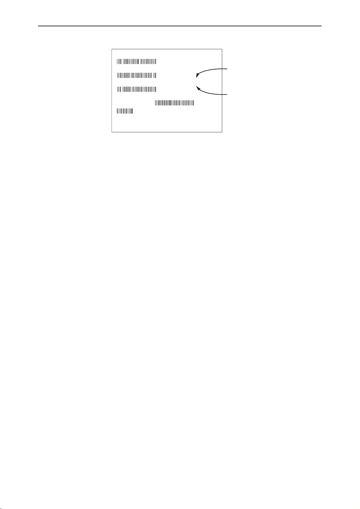
Figure 1: Serial number label on the underside of a Rapier 24i
Model : AT-RP241-10
Part Number: 990-11934-10
Product Serial Number: S03K225N
Quantity With Unit of
Measure:
1 EA 7 67035 14875
5
Made in Singapore
N or higher for maximum DS3
performance
J, K, L, or M for less demanding
DS3 applications
C613-03022-00 REV K
Page 7

6 Network Service Module
Hardware Overview
This section provides an overview of the hardware features of NSMs. NSMs are
expansion options for switch and router models with an NSM bay. NSMs slot
into a base-unit switch or router and either directly provide additional WAN
interfaces, or provide expansion slots for Port Interface Cards (PICs).
Hardware descriptions for your switch or router, Uplink Modules, and PICs
can be found in their respective Hardware References. These documents can be
downloaded from www.alliedtelesis.com/support/software.
Safety and conformance information can be found in the Installation and Safety
Guide or Safety and Statutory Information booklet for your switch or router,
which can be downloaded from www.alliedtelesis.com/support/software.
Common Features
The following hardware features are common to all NSM models.
Environmental
conditions
Regulatory
Standards
■ Operating temperature range: 0 ºC to 40 ºC (32 ºF to 104 ºF)
■ Storage temperature range: -25 ºC to 70 ºC (-13 ºF to 158 ºF)
■ Relative humidity range: 5 to 95% non-condensing
AT-AR0 40
■ Listing: UL, cUL, TUV
■ Safety: UL 60950-1, CAN/CSA-C22.2 No. 60950-1-03, EN60950-1,
AS/NZS60950.1
■ EMC: Radiated: EN55022 class A, FCC class A, VCCI class A,
AS/NZS CISPR22 class A
■ Immunity: EN55024
AT-AR041 and AT-AR042
■ Listing: TUV
■ Safety: EN60950-1, AS/NZS60950.1
■ EMC: Radiated: EN55022 class A, AS/NZS CISPR22 class A
■ Immunity: EN55024
■ Network interface: TBR3, ACA TS031, iDA ISDN 1
AT-AR0 48
■ Listing UL, cUL
■ Safety: UL60950-1, CAN/CSA-C22.2 No. 60950-1-03
■ EMC: Radiated: FCC Part 15 class A, IC-03 class A
■ Network interface: ANSI T1.102, ANSI T1.404, ANSI T1.107, ANSI T1.231
C613-03022-00 REV K
Page 8
Hardware Reference 7
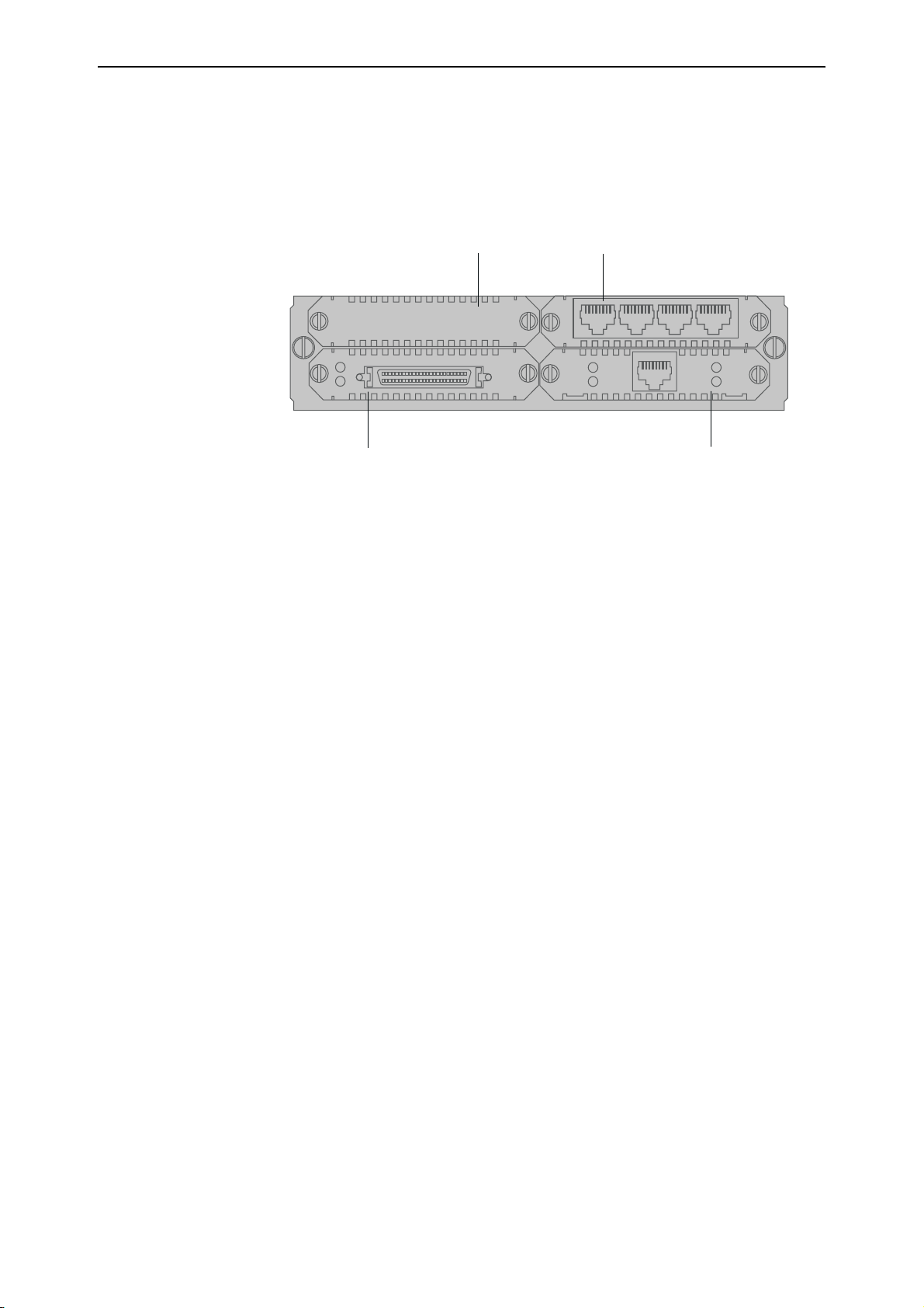
AT-AR040 NSM
The AT-AR040 provides four Port Interface Card (PIC) expansion bays for
installing PICs. The front panel of the AT-AR040 NSM is shown in Figure 2.
The AT-AR040 NSM does not have LEDs.
Figure 2: AT-AR040 NSM with three PICs installed
Tx
Rx
AT- AR 023 SYN PIC
Blank face-plate
SYN
024 ASYN4 PIC
AT- AR
30
ASYN
D Data
B Data
PRI E1/T1
AT- AR 020 PRI E1/T1 PIC
Active
N
T
nsm4pic3
Supported Port Interface Cards (PICs)
The following PICs can be installed in an AT-AR040 NSM:
■ AT-AR020 PRI E1/T1, a single ISDN Primary Rate E1/T1 interface
■ AT-AR021(S) BRI-S/T, a single ISDN Basic Rate S/T interface
■ AT-AR021(U) BRI-U, a single ISDN Basic Rate U interface
■ AT-AR023 SYN, a single 2Mbps synchronous interface supporting RS-232,
X.21, and V.35 in DTE and DCE modes
■ AT-AR024 ASYN4, four asynchronous ports
■ AT-AR027 VoIP-FXS, two Foreign Exchange Voice over IP ports
For more information about installing PICs, see the Port Interface Card
Installation and Safety Guide, which is included with every PIC or can be
downloaded from www.alliedtelesis.com/support/software.
For more information about the hardware features of PICs, constructing data
cables, and verifying installation, see the Port Interface Card Hardware Reference,
which can be downloaded from www.alliedtelesis.com/support/software.
Guidelines and limits for installing PICs
Observe the following guidelines and limits when installing PICs:
■ Use the PIC bays on the switch or router first, before installing PICs into an
AT-AR040 NSM.
■ Fill any PIC bays in the base router starting at bay 0.
■ Fill the PIC bays in the AT-AR040 NSM starting at bay 0.
■ You can install a maximum of two AT-AR020 PRI E1/T1 PICs into an
AT-AR040 NSM, and maximum of four total in a switch or router.
■ If two AT-AR020 PICs are installed in an AT-AR040 NSM, PIC one must be
installed in the lower row (bay 0 or 1) and the other PIC must be installed
in the upper row (bay 2 or 3).
C613-03022-00 REV K
Page 9

8 Network Service Module
■ If an AT-AR020 PIC is installed in an AT-AR040 NSM, and operating in E1
mode, you can not install an AT-AR021(S) or AT-AR021(U) PIC in the same
row of the NSM.
■ You can install a maximum of four AT-AR027 PICs in an AR745 router
fitted with an AT-AR040 NSM.
■ Avoid installing an AT-AR022 or AT-AR026 PIC in an AT-AR040 NSM.
Performance of these interfaces may be reduced and packet loss may occur.
Interface numbering
For each interface type (e.g. BRI, PRI, SYN, ETH, PORT), interfaces are
numbered starting at 0, in the following sequence:
1. interfaces on the base switch or router
2. interfaces on PICs installed in PIC bays on the base switch or router, starting
with PIC bay 0
3. interfaces on PICs installed in PIC bays on the AT-AR040 NSM, starting
with NSM PIC bay 0, and ending with NSM PIC bay 3.
C613-03022-00 REV K
Page 10

Hardware Reference 9
AT-AR041 and AT-AR042 NSMs
The AT-AR041 NSM provides eight ISDN Basic Rate S/T interfaces. The front
panel of the AT-AR041 is shown in Figure 3.
Figure 3: AT-AR041 NSM
6754 2310
Active
Data
The AT-AR042 NSM provides four ISDN Basic Rate S/T interfaces. The front
panel of the AT-AR042 is shown in Figure 4.
Figure 4: AT-AR042 NSM
2310
Active
Data
The BRI ports use RJ-45 connectors and provide TE interfaces. There are two
status LEDs per port. The functions of the LEDs are listed in Tab le 2 .
Table 2: AT-AR041 and AT-AR042 LEDs
LED State Function
Active Green Lit when the BRI has successfully completed the exchange
of INFO 1 and INFO 2 signals, and INFO 3 and INFO 4
signals are present on the link. This means the ISDN
interface is correctly connected to a working NT device.
Off There is no connection to the ISDN, or the ISDN has
deactivated the connection.
Data Amber For on-demand ISDN, lit when there is a call up over the
respective B channel.
For permanent circuits, lit when HDLC packets are being
exchanged between the switch or router and another TE
end system device (normally another switch or router)
over the respective B (data) channel.
Flashing Amber For on-demand ISDN, flashing when data is being
exchanged.
Off For on-demand ISDN, Off when there is no active
connection or when continuous data exchange is
occurring.
For permanent ISDN circuits, Off when no data exchange
is occurring.
C613-03022-00 REV K
The AT-AR041 and AT-AR042 support point-to-point links. Point to multipoint links are not supported.
Page 11

10 Network Service Module
Basic Rate ISDN Interfaces
Each Basic Rate S/T interface supports two 64kbit/s B channels and one
16kbit/s D channel, and operates in TE mode only. The switch or router should
be configured as a TE for normal operation.
User-configurable jumpers provide 100Ω line termination. By default, the
jumpers are factory set to terminate Rx and Tx, bridging terminals 2 and 3
(Figure 5 on page 10). To remove the line termination, move the jumpers so that
they bridge terminals 1 and 2.
Figure 5: Location of jumpers on BRI NSMs
RJ45 and LED blocks
Jumper set to Not Terminated
3 2 1
There are two jumpers per port. The AT-AR041 NSM,
therefore, has sixteen jumpers, while the AT-AR042 NSM has
eight jumpers. Each pair of jumpers set the Termination for the
port that they are closest to.
3 2 1
Jumper set to Terminated
(Factory default)
You should install the termination jumpers (terminate Rx and Tx) if:
■ termination is not provided by the building wiring, and
■ the device is the only TE device on a Point-to-Point link between the NT
and the TE, or the device is the last device on an S/T bus
You should remove the termination jumpers (not terminate Rx and Tx) if:
■ termination is provided by the building wiring, or
■ the device is one of a number of devices on an S/T bus, and is not the last
device on an S/T bus
C613-03022-00 REV K
Page 12

Hardware Reference 11
If you are unsure of whether to terminate the line or not, contact your ISDN
service provider or your authorised Allied Telesis distributor or reseller.
War ni ng
Do not attempt to change any jumpers on the NSM while the switch or
router is connected to a power supply or a live network. Disconnect the mains
power supply, any redundant power supply, and any cable attached to the ISDN
ports of the NSM. Dangerous voltages may be present on some parts of the NSM
board, even if the switch or router is powered off.
The BRI interfaces use RJ-45 connectors. Tab le 3 shows the pinout of the BRI
interfaces.
Table 3: Pinout of the Basic Rate ISDN S/T interfaces
Pin S/T Interface Functions
1-
2-
3TX+
4RX+
5RX-
6TX-
7-
8-
ISDN S/T Interface Cables
Figure 6 on page 11 shows how to wire a cable to connect a Basic Rate Interface
(BRI) to the ISDN network terminating equipment (NT).
Figure 6: Pin wiring diagram for an ISDN Basic Rate straight-through Interface cable
RJ45
(to switch or router)
Not connected
Not connected
→
→
←
←
TX+
TXRXRX+
Not connected
Not connected
Notes:
(1) → Output from switch or router; ← Input to switch or router.
(2) Use twisted pair cable, with pairs 3 and 6, and 4 and 5.
(3) Each wire is connected to the same pins at each end.
(4) Cable version 1.0.
1
2
3
6
5
4
7
8
1
2
3
6
5
4
7
8
RJ45
(to NT)
Not connected
Not connected
RX+
RXTXTX+
→
→
←
←
Not connected
Not connected
BRI1NT
C613-03022-00 REV K
Page 13

12 Network Service Module
Testing an AT-AR041 or AT-AR042 NSM
The Test Facility is built into the AlliedWare operating system, and is the best
method to verify the correct operation of the BRI interfaces on the AT-AR041
and AT-AR042 NSMs. Testing can be performed while the switch or router is
operational, but any interfaces being tested are dedicated to the Test Facility.
For more information about the Test Facility, see the Test Facility chapter of the
AlliedWare
When testing BRI interfaces using the Test Facility, a loopback plug must be
inserted into each interface being tested. The loopback plug connects the
output pins on the interface to the input pins so that any data transmitted over
the interface is looped back (hence loopback plug) and received at the same
interface. Figure 7 on page 12 shows how to construct loopback plug to test the
BRI interfaces.
Figure 7: BRI S/T loopback plug
®
Operating System Software Reference.
BRI Loopback Plug (RJ45 connector)
1
Not connected
2
Not connected
TX+
RX+
RXTX-
3
4
5
6
7
Not connected
8
Not connected
12345678
Switch end view
of plug
BRILOOPsw
To test a specific AT-AR041 or AT-AR042 interface, insert a BRI S/T loopback
plug into the interface and enter the command:
enable test interface=brin
where n is the interface number.
To test all AT-AR041 or AT-AR042 interfaces at once, insert BRI S/T loopback
plugs into all NSM BRI interfaces and enter the command:
enable test interface=expansion
Tests run for 4 minutes. Test status and results can be viewed at any time, using
the command:
show test
which produces a display like that shown in Figure 8 on page 13.
The status of the tests for each interface will be shown in the right-most column
of the output. For more information on the meanings of the other figures, see
the Tes t F ac i l i ty chapter of the AlliedWare
®
Operating System Software Reference
for your switch or router.
If you are unsure about running the Test Facility, or have difficulty evaluating
the results, contact your authorised Allied Telesis distributor or reseller.
C613-03022-00 REV K
Page 14

Hardware Reference 13
Figure 8: Example output from the show test command
Board ID Bay Board Name Host Id Rev Serial number
------------------------------------------------------------------------------Base 78 AR740 M1-15 46625812
PIC 38 0 AT-AR023-00 PIC Sync M1-1 5918255
NSM 95 AT-AR041-00 NSM 8BRI P1-3 46624968
Duration Details
Interface State Result Type (minutes) Data( %OK ) Control
---------------------------------------------------------------------------- eth0 complete good trans 0 - - TP 1 good(100.0) ENDEC 1 good(100.0) MAC 1 good(100.0) eth1 complete good trans 0 - - TP 2 good(100.0) ENDEC 0 - - MAC 2 good(100.0) syn0 testing wait continuous RS-232dte 355 good(100.0) good
dce 355 good(100.0) good
X.21 dte 354 good(100.0) good .
dce 0 - - V.35 dte 354 good(100.0) good
dce 0 - - asyn0 complete check this screen - 4 - - asyn1 complete good - 4 good(100.0) good
BRI0 complete good - 4 good(100.0) BRI1 complete good - 4 good(100.0) BRI2 complete good - 4 good(100.0) BRI3 complete good - 4 good(100.0) BRI4 complete good - 4 good(100.0) BRI5 complete good - 4 good(100.0) BRI6 complete good - 4 good(100.0) BRI7 complete good - 4 good(100.0) -
-----------------------------------------------------------------------------
For more complete testing, connect the BRI interface to an external ISDN test
device or NT mode device and use the enable bri ctest command and the
disable bri ctest command from the Integrated Services Digital Network (ISDN)
chapter the AlliedWare
®
Operating System Software Reference. This test will
execute conformance loopback tests and generate packets. If a test fails, please
contact your authorised Allied Telesis distributor or reseller.
C613-03022-00 REV K
Page 15

14 Network Service Module
AT-AR048 NSM
The AR048 NSM provides a single unchannelised DS3 interface with two BNC
connectors for transmit and receive. The front panel of the AT-AR048 NSM is
shown in Figure 9 and the functions of the LEDs are described in Tab le 4.
Figure 9: AT-AR048 NSM
RX TX
LOS
Loop
Activity
Table 4: AT-AR048 LEDs
LED State Function
Active Green Lit when the Line Interface Unit (LIU) is receiving a signal.
Loop Green Lit when any loopback is active.
LOS Amber Lit when the received signal is lost. This usually indicates a network
LOF Amber Lit when the DS3 framer cannot extract valid frames from the
AIS Amber Lit when an Alarm Indication Signal is detected.
FERF Amber Lit when a Far End Receive Failure signal is detected. This indicates
LOF
AIS
FERF
disruption, such as a cable being disconnected or a device failure.
received signal.
the far end is receiving an AIS, LOS, or LOF signal.
DS3 Interface
The AT-AR048 NSM provides a single standards-based unchannelised DS3
interface. The interface has the following features:
■ 44.736Mbit/s interface rate, 44.210Mbit/s payload data rate
■ Separate transmit (Tx) and receive (Rx) BNC connectors
■ 75Ω impedance
■ B3ZS line encoding
■ Automatic compensation for lines up to 135m (450feet)
■ Loop or internal timing
■ C-bit framing
■ Support for PPP and Frame Relay encapsulation
The interface meets the following specifications:
■ ANSI T1.103, Digital Hierarchy - Synchronous DS3 Format
■ ANSI T1.107, Digital Hierarchy - Formats
■ ANSI T1.231, Digital Hierarchy - Layer 1 In-Service Digital
■ RFC 2496 (DS3 MIB)
C613-03022-00 REV K
Page 16

Hardware Reference 15
DS3 Interface Cables
Use 75Ω RG59 coaxial cables with BNC connectors. Two cables are required,
one for transmit and one for receive. Neither cable should exceed 135m
(455feet) in length.
Testing an AT-AR048 NSM
The Test Facility is built into the AlliedWare operating system, and is the best
method to verify the correct operation of the DS3 interface on the AT-AR048
NSM. Testing can be performed while the switch or router is operational, but
any interfaces being tested are dedicated to the Test Facility. For more
information about the Test Facility, see the Test Facility chapter of the
AlliedWare
To test an AT-AR048 DS3 interface, connect a 75Ω RG59 cable between the
transmit and receive BNC connectors, and enter the command:
where n is the interface number.
Alternatively, enter the command:
®
Operating System Software Reference.
enable test interface=ds3n
enable test interface=expansion
Tests run for 4 minutes. Test status and results can be viewed at any time, using
the command:
show test
which produces a display like that shown in Figure 10.
Figure 10: Example output from the show test interface command for a DS3 interface
Board ID Bay Board Name Host Id Rev Serial number
------------------------------------------------------------------------------Base 114 AT-RP24i Rapier 24i M2-0 41376726
NSM DS3 187 AT-AR048 NSM DS3 M1-1 49986061
Duration Details
Interface State Result Type (minutes) Data( %OK ) Control
---------------------------------------------------------------------------- DS30 complete good - 4 good(100.0) -
-----------------------------------------------------------------------------
A more detailed output (with frame counts) can be displayed with the
command:
show test interface counter
C613-03022-00 REV K
which produces a display like that shown in Figure 11 on page 16.
For more information on the meanings of the output, see the see the Test Fa cil it y
chapter of the AlliedWare
®
Operating System Software Reference. If you are unsure
about running the Test Facility, have difficulty evaluating the results, or if a test
fails, contact your authorised Allied Telesis distributor or reseller.
Page 17

16 Network Service Module
Figure 11: Example output from the show test interface counter command for a DS3 interface
Board ID Bay Board Name Rev Serial number
---------------------------------------------------------------------------Base 114 AT-RP24i Rapier 24i M2-0 41376726
NSM DS3 187 AT-AR048 NSM DS3 M1-1 49986061
Duration Frame Counters
Interface State Type (minutes) Tx RxTotal RxGood RxBad
------------------------------------------------------------------------------- DS30 complete - 4 001045030 001045030 001045030 000000000
--------------------------------------------------------------------------------
C613-03022-00 REV K
Page 18

Hardware Reference 17
LEDs and What They Mean
The following LEDs report operations and faults on NSMs and related
hardware:
LEDs on the... Are described in ...
Switch and router base unit Ta bl e 5
AT-AR041 NSM Table 2 on page 9
AT-AR042 NSM Table 2 on page 9
AT-AR048 NSM Table 4 on page 14
AT-AR020 PRI E1/T1 PIC Table 6 on page 18
AT-AR021(S) BRI-S/T PIC Table 7 on page 18
AT-AR022 ETH PIC Table 8 on page 18
AT-AR023 SYN PIC Table 9 on page 19
AT-AR026 4ETH PIC Table 10 on page 19
AT-AR027 VoIP-FXS PIC Table 11 on page 19
The AT-AR040 NSM has no independent LEDs. See Ta bl e 5 for information
about related LEDs found on the base switch or router.
Switch and Router LEDs for NSMs
The following LEDs on switches and routers with NSM bays report operations
and faults on installed NSMs.
Table 5: Switch and Router LEDs for NSMs
LED State Function
In use Green An NSM is installed, is receiving power, and is operational.
The NSM and its PICs are not ready for hot swap.
Off No NSM is installed, or the NSM is not installed correctly
(the switch or router has not recognised the NSM).
Swap Green The NSM and its PICs are ready to be hot swapped.
Off The Hot Swap button must be pressed before the NSM or
its PICs can be hot swapped, or the software release does
not support hot swapping. Hot swapping is supported by
software version 2.3.1 or later.
C613-03022-00 REV K
Page 19

18 Network Service Module
PIC LEDs
The following LEDs report operations and faults on PICs, and may be helpful
when diagnosing possible AT-AR040 NSM operational faults. The LEDs are
located on the faceplate of the respective PIC. The AT-AR024 ASYN4 PIC does
not have LEDs.
Table 6: AT-AR020 PRI E1/T1 PIC LEDs
LED Function
D Data [ISDN mode only] Lit when HDLC packets are being exchanged between the
switch or router and the ISDN switch over the D (signalling) channel.
B Data Lit when HDLC packets are being exchanged between the switch or router
and another end system device (normally another switch or router) over any
of the B (data) channels.
Active Lit whenever operational (i.e., no RAI or AIS set) frames are being received
on the respective interface (PRI 0 or PRI 1) from another source.
NT [ISDN mode only] Lit when the PRI1 is operating in NT mode. This LED
should not be lit during normal operation.
Table 7: AT-AR021(S) BRI-S/T PIC LEDs
LED Function
B1, B2 For on-demand ISDN, lit when there is a call up over the respective B
channel and flashing when data is being exchanged.
For permanent circuits, lit when HDLC packets are being exchanged
between the switch or router and another TE end system device (normally
another switch or router) over the respective B (data) channel.
Active Lit when the BRI has successfully completed the exchange of INFO 1 and
INFO 2 signals, and INFO 3 and INFO 4 signals are present on the link. This
means that the ISDN interface is correctly connected to a working NT
device.
D Lit when HDLC packets are being exchanged between the switch or router
and the ISDN switch over the D (signalling) channel.
Table 8: AT-AR021(U) BRI-U PIC LEDs
LED Function
B1, B2 Lit when HDLC packets are being exchanged between the switch or router
and another TE end system device (normally another switch or router) over
the respective B (data) channel.
For ISDN, lit when there is a call up over the respective B channel and
flashing when data is being exchanged.
Active Lit when the U interface is in the Activated state (i.e., it is in a fully
operational at layer 1).
D Lit when HDLC packets are being exchanged between the switch or router
and the ISDN switch over the D (signalling) channel.
C613-03022-00 REV K
Page 20

Hardware Reference 19
Table 9: AT-AR023 SYN PIC LEDs
LED Function
Tx Lit when data is being transmitted over the synchronous interface.
Rx Lit when data is being received on the synchronous interface.
Table 10: AT-AR026 4ETH PIC LEDs
LED Function
Left Lit when the port is operating at 100Mbps and full duplex.
Right Lit when a link has been established. Flashing when data is being
transmitted through the port.
Table 11: AT-AR027 VoIP-FXS PIC LEDs
LED State Function
Off Hook/Ring Off The port is on-hook.
Green The port is off-hook.
Flashing An incoming call is present on the port.
PIC Reg Off The PIC is not registered with a gatekeeper and external
phone calls cannot be made.
Flashing The PIC is registered with a gatekeeper or gatekeeper
has been set to “None”. External calls can only be made
if the PIC is registered with a gatekeeper.
PIC Error
Off The PIC is okay.
Green An internal error has occurred. Reset the PIC using the
reset voip command.
C613-03022-00 REV K
Page 21

20 Network Service Module
Hot Swapping
Hot swapping is the installation or removal of a component such as an NSM
without powering down or restarting the switch or router.
NSMs can be hot swapped in and out of switches and routers that are running
Software Version 2.3.1 or later. To find out which software version your switch
or router is running, use the command:
show system
See the Network Service Module Installation and Safety Guide for instructions on
how to hot swap your NSM.
Hot Swapping the AT-AR040 NSM with PICs
Caution You cannot hot swap PICs. Before installing or removing a PIC from a
PIC bay in a switch or router, you must disconnect all power sources to the
switch or router. To install or remove a PIC from an AT-AR040 NSM, you must
first either physically remove the NSM from the switch or router using the hot
swap method, or disconnect all power sources to the switch or router.
You can hot swap the AT-AR040 NSM with PICs installed in its PIC bays. There
is no need to remove the PICs before hot swapping the NSM.
When an AT-AR040 NSM with PIC cards is hot swapped out, and an identical
combination of AT-AR040 and PICs is hot swapped into the same bay, the
software configurations for the PIC interfaces are preserved across the hot
swap. In this case, software modules configured to the PIC interfaces transfer
to the newly swapped in interfaces.
When an AT-AR040 NSM with PICs is hot swapped out and a different
combination of AT-AR040 and PICs is hot swapped into the same bay, new
interface instances are created for any new PIC types or PIC types that are in
different bays, and the old interface instances are discarded. For any PIC in the
combination that is replaced by a PIC of the same type, interface instances are
preserved.
Behaviour of Hot Swapped Interfaces
When an NSM is hot swapped out, its interface instances become dormant.
They stay dormant until either another interface of the same type is hot
swapped into the bay, in which case they are reactivated, or an interface of a
different type is hot swapped into the bay, in which case they are discarded.
Dormant interfaces are included in the show interface command output
(Figure 12 on page 21 and Figure 13 on page 21) and in the SNMP interfaces
MIB, marked as swapped out. In other switch or router commands, however,
the switch or router behaves as though dormant interfaces do not exist.
Instances of higher-level modules such as LAPD, Q931, ISDN call control, PPP,
and IP do not become dormant when an interface becomes dormant. Instead
they behave as if the interface has stopped communicating, for example, as if
the cable has been unplugged.
C613-03022-00 REV K
Page 22

Hardware Reference 21
The configuration script is not scanned for commands relating to hot-inserted
interfaces until the switch or router is restarted. These interfaces must be
configured manually.
The switch or router does not update the MAC address of any hot-swapped
Ethernet interface until the switch or router is restarted.
All other commands that show or set interface properties behave as if swapped
out interfaces do not exist. Commands that operate on multiple interfaces skip
swapped out interfaces. Commands specified explicitly to a dormant interface
display an error message.
Figure 12: Example output from the show interface command
Interfaces sysUpTime: 00:00:46
DynamicLinkTraps.....Disabled
TrapLimit............20
Number of unencrypted PPP/FR links.....0
ifIndex Interface ifAdminStatus ifOperStatus ifLastChange
----------------------------------------------------------------------------- 1 eth0 Up Up 00:00:03
2 eth1 Up Down 00:00:00
3 bri0 Up Swapped out 00:00:43
4 eth2 Up Swapped out 00:00:42
------------------------------------------------------------------------------
Interface name summary
Interface Full name
-----------------------------------------------------------------------------asyn0 asyn0
asyn1 asyn1
eth0 eth0
eth1 eth1
------------------------------------------------------------------------------
Figure 13: Example output from the show interface command for a specific interface
Interface.................. bri0
ifIndex.................. 3
ifMTU.................... 1712
ifSpeed.................. 144000
ifAdminStatus............ Up
ifOperStatus............. Swapped out
ifLinkUpDownTrapEnable... Disabled
TrapLimit................ 20
Interface Counters
ifInOctets .................. 52190 ifOutOctets ................. 52190
ifInUcastPkts ................ 3070 ifOutUcastPkts ............... 3071
ifInNUcastPkts .................. 0 ifOutNUcastPkts ................. 0
ifInDiscards .................... 0 ifOutDiscards ................... 0
ifInErrors ...................... 0 ifOutErrors ..................... 0
C613-03022-00 REV K
Page 23

22 Network Service Module
Troubleshooting
This section provides information on how to detect and resolve problems with NSMs.
Performing the following tasks will eliminate the most common faults.
1. Check that the NSM is correctly installed. See the Network Service Module
Installation and Safety Guide for a step by step guide to installing NSMs.
2. Make sure the power cord is securely connected to the switch or router and
the power outlet.
3. Check that the power supply voltage to the switch or router is stable.
4. Check that the correct data cables are being used and that their connections
are secure.
5. Make sure that other network devices are working properly.
6. Use the show install command to check that the latest software release is
loaded. The AlliedWare
®
Operating System Software Reference for your switch
or router has more information about obtaining and installing the latest
software release.
7. If the switch or router is malfunctioning, reboot it by pressing the recessed
Reset button or entering the command restart reboot. Alternatively, power
off and on the switch or router by disconnecting and reconnecting the main
power supply and, if connected, the RPS power.
Other sources of troubleshooting information are:
■ The Installation and Safety Guide or Quick Install Guide for your switch or
router, which can be downloaded from
www.alliedtelesis.com/support/software.
■ The Hardware Reference for your switch or router, which can be
downloaded from www.alliedtelesis.com/support/software.
■ www.alliedtelesis.com
C613-03022-00 REV K
Page 24

Hardware Reference 23
Obtaining Documentation and Resources
Document set The complete document set for Network Service Modules includes:
■ this Hardware Reference, which contains detailed information on the
hardware features of Network Service Modules
■ the Network Service Module Installation and Safety Guide, which describes
how to install a Network Service Module
■ the Port Interface Card Installation and Safety Guide, which describes how to
install a Port Interface Card
■ the Port Interface Card Hardware Reference, which contains detailed
information on the hardware features of Port Interface Cards
■ the Installation and Safety Guide, or Quick Install Guide and Safety and
Statutory Information for your switch or router, which describes how to
install the switch or router and includes important safety and statutory
information
■ the Hardware Reference for your switch or router, which contains detailed
information on the hardware features of your switch or router
■ the AlliedWare® Operating System Software Reference for your switch or
router, which contains detailed information on configuring WAN and
routing protocols to use PICs
You can download these documents and updates from
www.alliedtelesis.com/support/software.
You need Adobe® Acrobat® Reader® to view, search, or print these
documents. You can download it from www.adobe.com.
Other resources How-To Notes describe a range of standard Allied Telesis solutions, and
include technical tips and guides to configuring specific hardware and
software features. You can download the latest How-To Notes from
www.alliedtelesis.com/resources/literature/howto.aspx.
MIBs supported by Allied Telesis products can be downloaded from
www.alliedtelesis.com/support/software.
Microsoft® Visio® stencils for Allied Telesis products can be downloaded from
www.alliedtelesis.com/resources/images/visio.aspx.
AT-TFTP Server for Windows is a TFTP (Trivial File Transfer Protocol) server for
transferring software versions, configuration scripts and other files between a
PC and your switch or router. You download AT-TFTP Server from
www.alliedtelesis.com/support/software.
C613-03022-00 REV K
CD-ROM
Some products ship with a Documentation and Tools CD-ROM, which includes:
■ the complete document set
■ Adobe® Acrobat® Reader®
■ AT-TFTP Ser v er
■ Supported MIBs
■ How-To Notes, white papers, Microsoft® Visio® stencils and other
resources
■ Tryouts of networking software
Page 25

24 Network Service Module
Contacting us With locations covering all of the established markets in North America, Latin
America, Europe, Asia, and the Pacific, Allied Telesis provides localized sales
and technical support worldwide. To find the representative nearest you, visit
us on the Web at www.alliedtelesis.com.
C613-03022-00 REV K
 Loading...