

Page 1
2914 Series
Fiber Network Adapters with Wake on LAN (WoL)
AT-2914SX/SC
AT-2914SX/LC
AT-2914SP
AT-2914GP/SP
Installation and User’s Guide
613-002358 Rev. B
Page 2

Copyright 2020 Allied Telesis, Inc.
All rights reserved. No part of this publication may be reproduced without prior written permission from Allied Telesis, Inc.
Microsoft and Internet Explorer are registered trademarks of Microsoft Corporation. Netscape Navigator is a registered
trademark of Netscape Communications Corporation. All other product names, company names, logos or other
designations mentioned herein are trademarks or registered trademarks of their respective owners.
Allied Telesis, Inc. reserves the right to make changes in specifications and other information contained in this document
without prior written notice. The information provided herein is subject to change without notice. In no event shall Allied
Telesis, Inc. be liable for any incidental, special, indirect, or consequential damages whatsoever, including but not limited to
lost profits, arising out of or related to this manual or the information contained herein, even if Allied Telesis, Inc. has been
advised of, known, or should have known, the possibility of such damages.
Page 3

Electrical Safety and Emissions
Standards
This product meets the following standards:
Federal Communications Commission Interference Statement
Declaration of Conformity
Manufacturer Name: Allied Telesis, Inc.
Declares that the product: Fiber Network Adapter with WoL
Model Number: AT-2914SX/SC, AT-2914SX/LC, AT-2914SP, AT-2914GP/SP
This device complies with Part 15 of the FCC Rules. Operation is subject to the following two
conditions: (1) This device may not cause harmful interference, and (2) this device must accept
any interference received, including interference that may cause undesired operation.
This equipment has been tested and found to comply with the limits for a Class B digital device,
pursuant to Part 15 of the FCC Rules. These limits are designed to provide reasonable protection
against harmful interference in a residential installation. This equipment generates, uses and can
radiate radio frequency energy and, if not installed and used in accordance with the instructions,
may cause harmful interference to radio communications. However, there is no guarantee that
interference will not occur in a particular installation. If this equipment does cause harmful
interference to radio or television reception, which can be determined by turning the equipment
off and on, the user is encouraged to try to correct the interference by one of the following
measures:
Reorient or relocate the receiving antenna.
Increase the separation between the equipment and receiver.
Connect the equipment into an outlet on a circuit different from that to which the receiver is
connected.
Consult the dealer or an experienced radio/TV technician for help.
Caution
Any changes or modifications not expressly approved by the party responsible for compliance
could void the user's authority to operate this equipment. E80
Avertissement
Les changements ou modifications non expressément approuvés par la partie responsable de
la conformité pourraient annuler l'autorité de l'utilisateur à utiliser cet équipement. E80
3
Page 4

European Union Restriction of the Use of Certain Hazardous
Substances (RoHS) in Electrical and Electronic Equipment
This Allied Telesis RoHS-compliant product conforms to the European Union Restriction of the
Use of Certain Hazardous Substances (RoHS) in Electrical and Electronic Equipment. Allied
Telesis ensures RoHS conformance by requiring supplier Declarations of Conformity, monitoring
incoming materials, and maintaining manufacturing process controls.
Safety and Electromagnetic Emissions Certificates
Standard Compliance
CE
RoHs compliant
European Union RoHS (Directive 2011/65/EU of the European Parliament and of the Council
of 8 June 2011 on the restriction of the use of certain hazardous substances in electrical and
electronic equipment.)
Electromagnetic Compatibility (EMC)
VCCI Class B (except AT-2914GP)
EN55032
– Class A (AT-2914GP)
– Class B (all other models)
EN55035
FCC Part 15B
– Class A (AT-2914GP)
– Class B (all other models)
Safety
UL60950-1 (except AT-2914GP)
UL62368-1 (AT-2914GP)
CSA22.2 No.60950-1-07 (except AT-2914GP)
TUV EN60950-1 (except AT-2914GP)
TUV EN62368-1 (AT-2914GP)
4
Page 5

Translated Safety Statements
Important: The indicates that a translation of the safety statement is available in a PDF document
titled “Translated Safety Statements” on the Allied Telesis website at www.alliedtelesis.com/
support.
Remarque: Les consignes de sécurité portant le symbole sont traduites dans plusieurs langues
dans le document Translated Safety Statements, disponible à l'adresse alliedtelesis.com.
5
Page 6

6
Page 7

Table of Contents
Preface ............................................................................................................................................................ 11
Safety Symbols Used in this Document..................................................................................................... 12
Contacting Allied Telesis............................................................................................................................ 13
Chapter 1: Introduction ................................................................................................................................. 15
Description ................................................................................................................................................. 16
2914 Series Products .......................................................................................................................... 17
Duplex SC Fiber Optic Connector ....................................................................................................... 17
LC Fiber Optic Adapter........................................................................................................................ 17
SFP Slot .............................................................................................................................................. 18
LED...................................................................................................................................................... 18
Twisted Pair Copper Port .................................................................................................................... 19
The AT-2914GP/SP Network Adapter ....................................................................................................... 20
Power over Ethernet (PoE).................................................................................................................. 20
AT-2914GP-PSU Power Cord ............................................................................................................. 21
Console Port........................................................................................................................................ 21
Bridge to Connect Two Ports to One Network..................................................................................... 21
Model Naming Conventions....................................................................................................................... 23
Supported Operating Systems................................................................................................................... 24
Accessing Documents................................................................................................................................ 25
Contents of Your Shipment........................................................................................................................ 26
Warranty Registration ................................................................................................................................ 27
Chapter 2: Installing the Hardware .............................................................................................................. 29
System Requirements................................................................................................................................ 30
Reviewing Safety Precautions ................................................................................................................... 31
Pre-Installation Checklist............................................................................................................................ 33
Replacing the Bracket................................................................................................................................ 34
Installing a Network Adapter ...................................................................................................................... 36
Connecting the AT-2914GP-PSU Power Cord to the AT-2914GP/SP Network Adapter........................... 40
Connecting the Network Cables................................................................................................................. 41
Connecting a Fiber Optic Network Cable ............................................................................................ 41
Connecting an SFP Transceiver.......................................................................................................... 41
Chapter 3: Installing the Driver Software .................................................................................................... 43
Overview .................................................................................................................................................... 44
Guidelines............................................................................................................................................ 44
Installing the Driver Using Device Manager ........................................................................................ 44
Installing the Driver Using the Silent Installation Method .................................................................... 44
Downloading the Driver Software............................................................................................................... 45
Accessing the Device Manager.................................................................................................................. 48
Installing the Driver Software ..................................................................................................................... 49
Updating the Driver Software..................................................................................................................... 52
Performing the Silent Installation ............................................................................................................... 53
Installing the Driver Silently ................................................................................................................. 53
Viewing Supported DPInst Options ..................................................................................................... 54
7
Page 8

2914 Series Gigabit Ethernet Network Adapters with WoL Installation and User’s Guide
Chapter 4: Configuring the VLAN and Priority ............................................................................................55
Overview.....................................................................................................................................................56
Accessing the CLI on the AT-2914GP/SP Network Adapter ......................................................................57
Guidelines ............................................................................................................................................57
What to Prepare................................................................................................................................... 57
Accessing the CLI on the Adapter for the First Time ...........................................................................57
Installing the Serial Port Driver Manually .............................................................................................58
Accessing the CLI Using a Terminal Emulator Program......................................................................59
Configuring the VLAN and Priority Settings on the Network Adapter.........................................................60
Enabling the VLAN Tagging.................................................................................................................61
Disabling the VLAN Tagging................................................................................................................ 61
Changing the VLAN ID for the PoE Copper Port .................................................................................62
Changing the QoS Priority Level for the PoE Copper Port ..................................................................62
Changing the VLAN ID for the PC Traffic.............................................................................................63
Changing the QoS Priority Level for the PC Traffic..............................................................................63
Chapter 5: Configuring a VoIP Phone System ............................................................................................65
Overview.....................................................................................................................................................66
Configuring VLAN Tagging on Adapter Ports.............................................................................................67
VLAN Tagging Combinations...............................................................................................................67
Using VLAN-Capable VoIP Phones to Set up VLAN ...........................................................................68
Using AT-2914GP/SP to Set up VLAN ................................................................................................68
Non-VLAN Application .........................................................................................................................68
Chapter 6: Modifying Advanced Properties ................................................................................................69
Overview.....................................................................................................................................................70
Guidelines ............................................................................................................................................70
Accessing Advanced Properties.................................................................................................................71
802.3az EEE...............................................................................................................................................72
ARP Offload................................................................................................................................................73
Ethernet@WireSpeed.................................................................................................................................74
Flow Control ...............................................................................................................................................75
Interrupt Moderation ...................................................................................................................................77
Jumbo Mtu..................................................................................................................................................78
Large Send Offload v2 (IPv4) .....................................................................................................................79
Large Send Offload v2 (IPv6) .....................................................................................................................80
Maximum Number of RSS Queues ............................................................................................................81
Network Address ........................................................................................................................................83
NS Offload ..................................................................................................................................................85
Priority & VLAN...........................................................................................................................................86
Receive Side Scaling..................................................................................................................................88
Speed & Duplex..........................................................................................................................................89
TCP/UDP Checksum Offload (IPv4)...........................................................................................................91
TCP/UDP Checksum Offload (IPv6)...........................................................................................................93
VLAN ID......................................................................................................................................................95
Wake on Magic Packet...............................................................................................................................96
Wake on Pattern Match .............................................................................................................................. 97
WOL Speed ................................................................................................................................................98
Chapter 7: Uninstalling the Driver Software ................................................................................................99
Overview...................................................................................................................................................100
Guidelines ..........................................................................................................................................100
Uninstalling the Driver Software Using Device Manager..........................................................................101
Uninstalling the Driver Software Silently...................................................................................................102
Chapter 8: Troubleshooting ........................................................................................................................103
Checking the Port LED on the Adapter ....................................................................................................104
8
Page 9

Contents
LED on AT-2914SX/SC and AT-2914SX/LC..................................................................................... 104
LEDs on AT-2914SGP/SP................................................................................................................. 104
Fiber Optic Ports ...................................................................................................................................... 105
Twisted Pair Ports.................................................................................................................................... 107
Testing Network Connectivity................................................................................................................... 109
Guidelines.......................................................................................................................................... 109
Windows ............................................................................................................................................ 109
Linux .................................................................................................................................................. 110
Appendix A: Specifications ........................................................................................................................ 111
Physical Specifications............................................................................................................................. 111
Environmental Specifications................................................................................................................... 111
Power Specifications................................................................................................................................ 111
Optical Specifications............................................................................................................................... 112
RJ-45 Twisted Pair Port Pinouts .............................................................................................................. 113
9
Page 10

2914 Series Gigabit Ethernet Network Adapters with WoL Installation and User’s Guide
10
Page 11

Preface
This manual is the installation and user’s guide for the 2914 Series of Fiber
Network Adapters with WoL. The network adapters included in this series
are:
AT-2914SX/SC
AT-2914SX/LC
AT-2914SP
AT-2914GP/SP
The Preface contains the following sections:
“Safety Symbols Used in this Document” on page 12
“Contacting Allied Telesis” on page 13
11
Page 12
2914 Series Fiber Network Adapters with WoL Installation and User’s Guide
Safety Symbols Used in this Document
This document uses the following conventions:
Note
Notes provide additional information.
Caution
Cautions inform you that performing or omitting a specific action
may result in equipment damage or loss of data.
Warning
Warnings inform you that performing or omitting a specific action
may result in bodily injury.
Warning
Warnings inform you that an eye and skin hazard exists due to the
presence of a Class 1 laser device.
12
Page 13

Contacting Allied Telesis
If you need assistance with this product, you may contact Allied Telesis
technical support by going to the Support & Services section of the Allied
Telesis web site at www.alliedtelesis.com/support. You can find links for
the following services on this page:
24/7 Online Support - Enter our interactive support
center to search for answers to your questions in our
knowledge database, check support tickets, learn
about Return Merchandise Authorization (RMA), and
contact Allied Telesis technical experts.
USA and EMEA phone support - Select the phone
number that best fits your location and customer type.
Hardware warranty information - Learn about Allied
Telesis warranties and register your product online.
Replacement Services - Submit an RMA request via
our interactive support center.
Preface
Documentation - View the most recent installation
guides, user guides, software release notes, white
papers and data sheets for your product.
Software Updates - Download the latest software
releases for your product.
For sales or corporate contact information, go to
www.alliedtelesis.com/purchase and select your region.
13
Page 14

2914 Series Fiber Network Adapters with WoL Installation and User’s Guide
14
Page 15

Chapter 1
Introduction
This chapter provides an introduction to the 2914 Series of Fiber Optic
Network Adapters with WoL.
This chapter contains the following sections:
“Description” on page 16
“The AT-2914GP/SP Network Adapter” on page 20
“Supported Operating Systems” on page 24
“Accessing Documents” on page 25
“Contents of Your Shipment” on page 26
“Warranty Registration” on page 27
15
Page 16
2914 Series Fiber Network Adapters with WoL Installation and User’s Guide
Description
The 2914 fiber network adapter series is a 100/1000Mb Ethernet PCI
Express (PCIe) card equipped with one fiber optic port or SFP slot. The
AT-2914GP/SP model comes with one copper port with Power over
Ethernet (PoE) capability in addition to the SFP fiber slot.
The 2914 network adapters support the Wake-on-LAN (WoL) feature.
WoL is a protocol for remotely turning on a computer in a low power mode
with a network message. A magic packet is a network message that a
WoL-enabled computer receives and wakes up when the computer’s MAC
address matches one in the magic packet.
The AT-2914SX/SC and AT-2914SX/LC models are Gigabit Ethernet
network adapters operating at 1000Mbps. The AT-2914SP and
AT-2914GP/SP models can operate at 100Mbps or 1000Mbps depending
on the SFP type in use. The copper port on the AT-2914GP/SP model can
operate at 10, 100, or 1000Mbps.
If you installed the network adapter on your Windows platform, you must
install network adapter driver software. For instructions, see Chapter 3,
“Installing the Driver Software” on page 43.
Note
You do not need to install network adapter driver software for Linux
systems because Linux has inbox drivers for the network adapters.
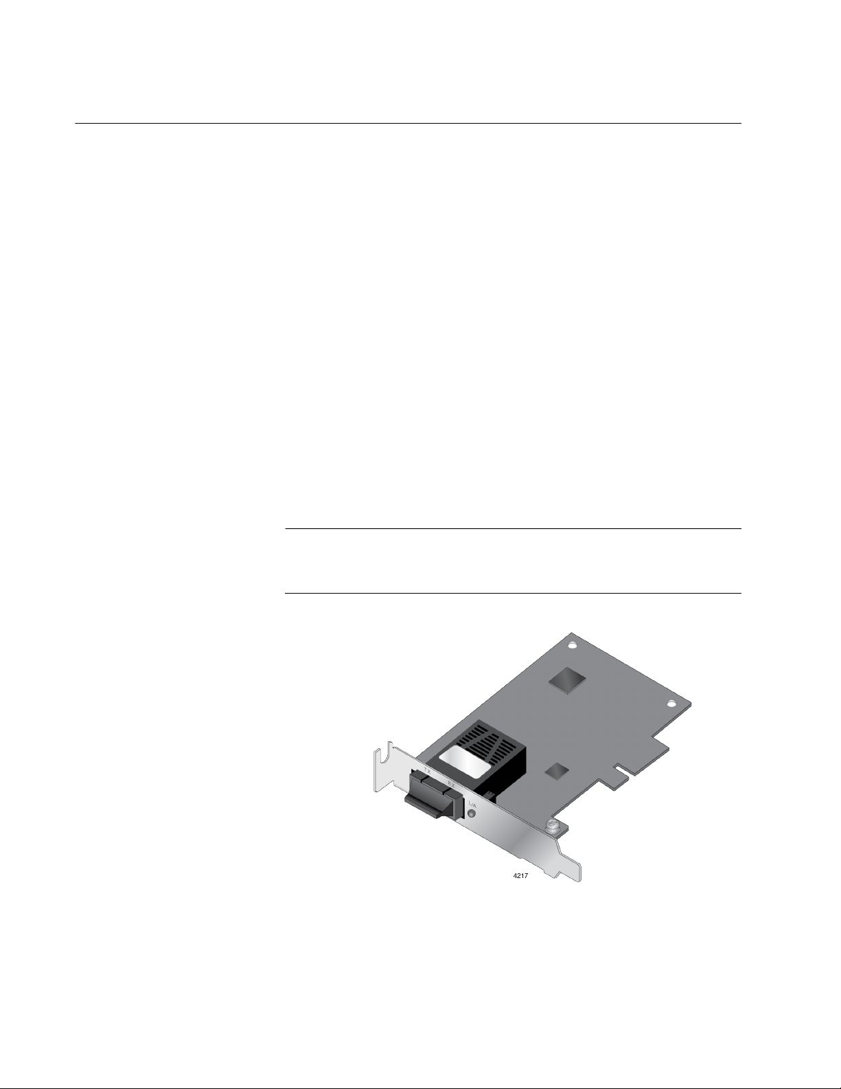
Figure 1 shows the AT-2914SX/SC model.
16
Figure 1. AT-2914SX/SC Network Adapter
Page 17
Chapter 1: Introduction
2914 Series
Products
Duplex SC Fiber
Optic Connector
The AT-2914 series includes the following models:
AT-2914SX/SC network adapter
AT-2914SX/LC network adapter
AT-2914SP network adapter
AT-2914GP/SP network adapter
The AT-2914GP/SP model can use the optional power supply:
AT-2914GP-PSU power supply unit
Note
For more information about the AT-2914GP/SP network adapter and
AT-2914GP-PSU power supply unit, see “The AT-2914GP/SP
Network Adapter” on page 20.
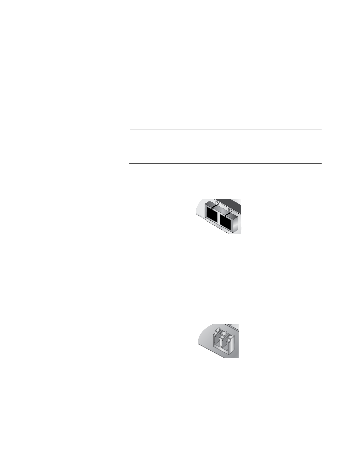
The AT-2914SX/SC network adapter is equipped with a 1000BASE-SX
port with a duplex SC connector. See Figure 2.
LC Fiber Optic
Adapter
Figure 2. SC Fiber Optic Connector
The duplex SC port has the following cable requirements:
50/125 µm (core/cladding) multimode fiber optic cable up to 500m
62.5/125 µm (core/cladding) multimode fiber optic cable up to
220m
The AT-2914SX/LC network adapter is equipped with a 1000BASE-SX
port with the LC connector. See Figure 3.
Figure 3. LC Fiber Optic Connector
17
Page 18
2914 Series Fiber Network Adapters with WoL Installation and User’s Guide
The duplex LC port has the following cable requirements:
50/125 µm (core/cladding) multimode fiber optic cable up to 500m
62.5/125 µm (core/cladding) multimode fiber optic cable up to
220m
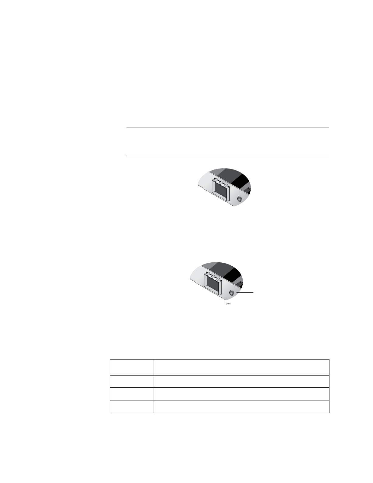
SFP Slot The AT-2914SP and AT-2914GP/SP adapters have SFP slots for
100Mbps or 1000Mbps SFP transceivers. The ports operate in full-duplex
mode only. See Figure 4.
Note
An SFP transceiver must be purchased separately. For a list of
supported transceivers, see the product’s data sheet.
Figure 4. SFP Slot
LED The fiber optic port on the network adapter comes with one LED on the
front panel as shown in Figure 5. The LED indicates the link and activity
status of the port.
LED
Figure 5. LED Except AT-2914GP/SP
Table 1 describes the link states of the LED except for the AT-2914GP/SP
model.
Table 1. LED Status Except AT-2914GP/SP
State Description
On Valid link.
18
Off No link.
Flashing The port is receiving or transmitting network packets.
Page 19
Chapter 1: Introduction
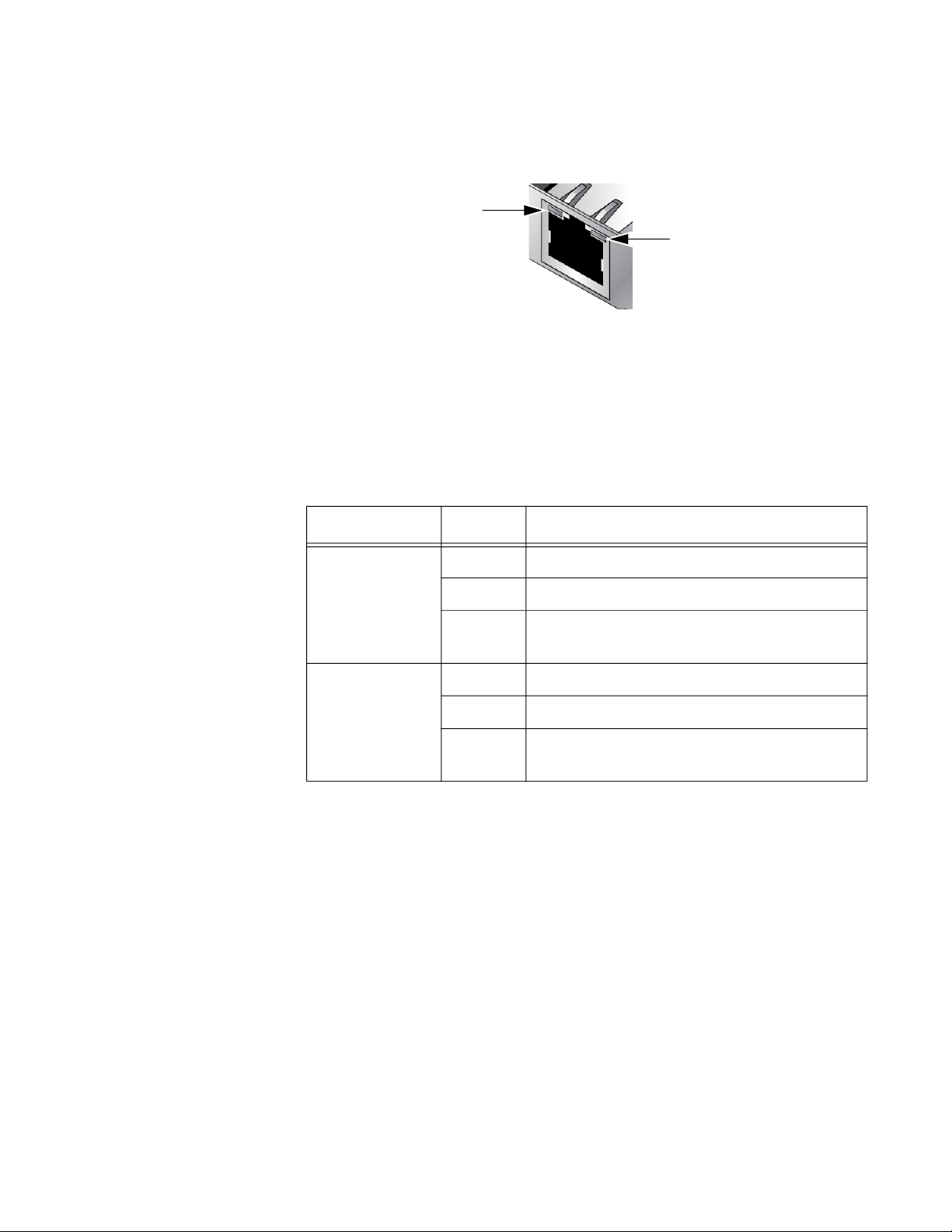
Twisted Pair
Copper Port
The AT-2914GP/SP network adapter is equipped with a PoE+ copper port
for a 10/100/1000BASE-T twisted pair cable. See Figure 6.
LED for Twisted Pair Port
LED for Fiber Optic Port
Figure 6. Twisted Pair Port and LEDs
The minimum cable requirement for the AT-2914GP/SP network adapter
is a TIA/EIA 568-B-compliant Enhanced 5 (Cat 5e) unshielded cable.
The twisted pair port has two LEDs. For link states and descriptions, see
Table 2.
Table 2. LED Status for the Twisted Pair Port on AT-2914GP/SP
LED State Description
On Valid link on the twisted pair port
Top-left LED
(For Twisted
Pair Port)
Off No link on the twisted pair port
Flashing The twisted pair port is receiving or
transmitting network packets.
Top-right LED
(For Fiber Port)
On Valid link on the fiber optic port
Off No link on the fiber optic port
Flashing The fiber optic port is receiving or
transmitting network packets.
19
Page 20
2914 Series Fiber Network Adapters with WoL Installation and User’s Guide
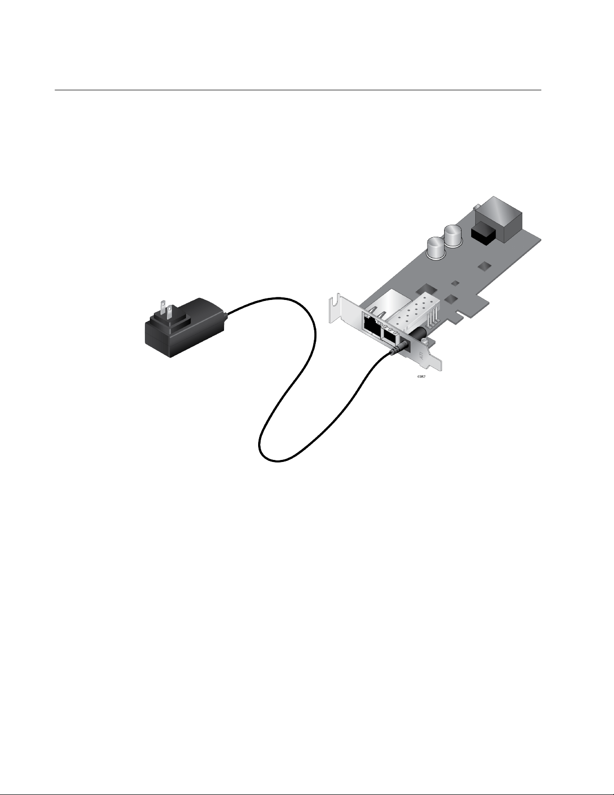
The AT-2914GP/SP Network Adapter
The AT-2914GP/SP network adapter is equipped with an SFP slot and a
twisted pair copper port with Power over Ethernet Plus (PoE+) capability.
The adapter can supply power to the PoE+ copper port from the PCIe slot
or an optional external power supply, the AT-2914GP-PSU unit. See
Figure 7.
Power over
Ethernet (PoE)
20
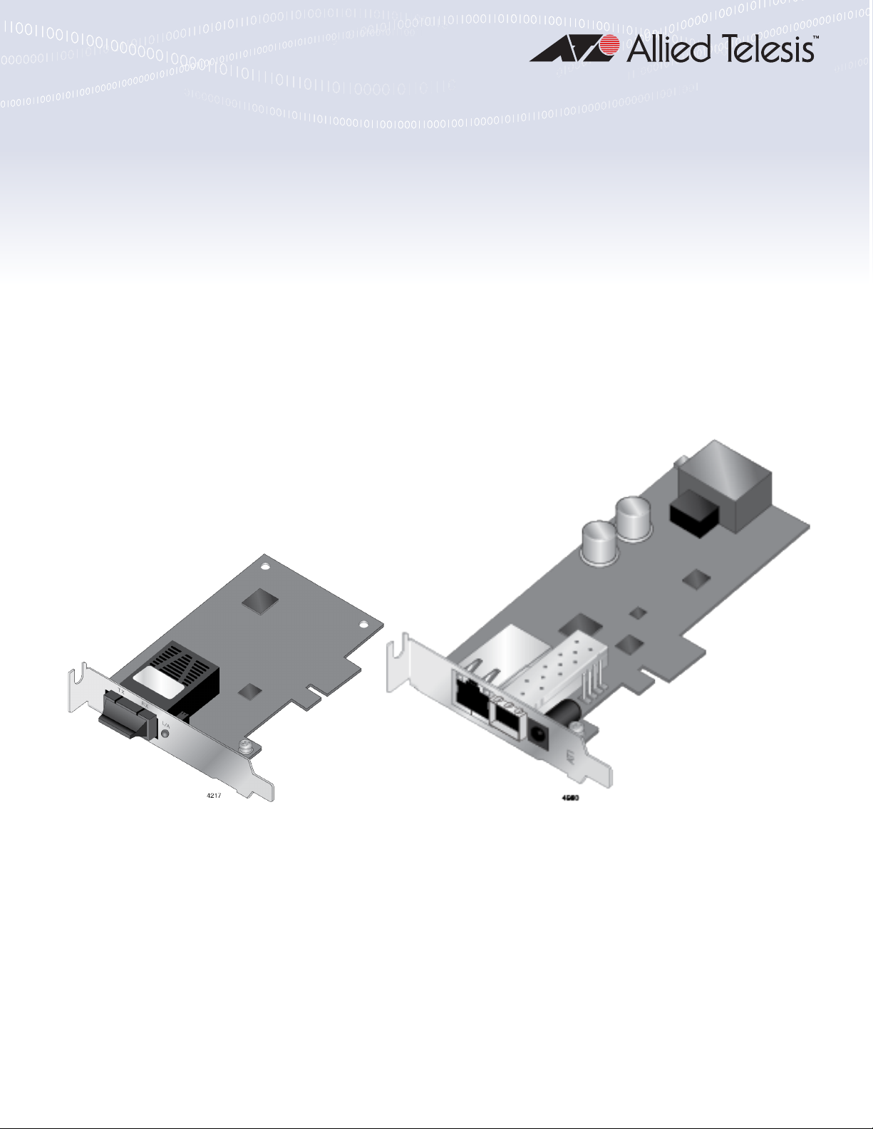
Figure 7. AT-2914GP/SP Adapter and AT-2914GP-PSU Product
The network adapter is used as a bridge that connects two ports on the
adapter to the same network. The adapter appears to the PC as a single
port network adapter, like other 2914 series adapters. The data from the
copper port and the PC is routed directly to the fiber port without any
interaction from the system.
Optional configurable VLAN ID's can be used to tag and segregate the
packets egressing onto the fiber connection. For more information, see
Chapter 4, “Configuring the VLAN and Priority” on page 55.
PoE is a system that supports power along with data using a single
Ethernet cable. Power over Ethernet Plus (PoE+) is a PoE standard for
devices that provide power up to 25.5 watts. The AT-2914GP/SP network
adapter with the AT-2914GP-PSU supports PoE+.
Page 21
Chapter 1: Introduction
AT-2914GP-PSU
Power Cord
When the optional AT-2914GP-PSU power cord is plugged into an AC
power supply and connected to the AT-2914GP/SP adapter, the adapter
can provide a Powered Device (PD) connected to the adapter through the
copper port up to 25.5W of power.
Without the AT-2914GP-PSU power supply unit, the AT-2914GP/SP
adapter provides the PD with limited power, depending on the capability of
the system's PCIe 12V power rail. It is typically 10-15W; however, verify
your system's specifications and derate by 20% for planning purposes.
In addition to providing more power to the PD, with the AT-2914GP-PSU
power supply unit, the adapter allows communications even when the
system where the AT-2914GP/SP adapter is installed is powered off.
When the AT-2914GP-PSU power supply unit is present, the
AT-2914GP/SP adapter uses the power supply unit to provide power to
the PD and does not use 12V power from the PCIe slot.
Console Port The AT-2914GP/SP network adapter is equipped with a USB Micro-B
receptacle that functions as a Console port. By connecting the adapter
and your management PC to the Console port, you can access the
Command Line Interface (CLI) to manage the VLAN and priority of the
adapter.
Bridge to
Connect Two
Ports to One
Network
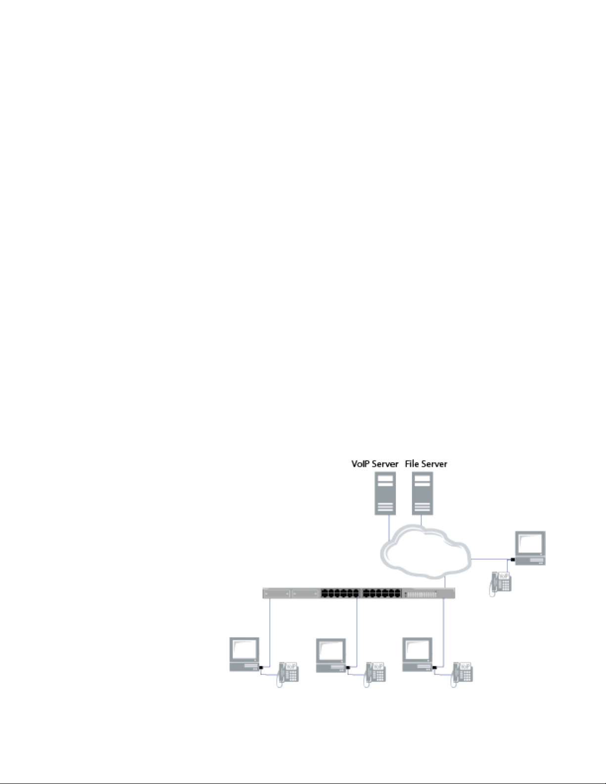
The AT-2914GP/SP adapter is designed to connect a PC and a PoE
powered device to an Ethernet network. A PoE powered device can be a
Voice over IP (VoIP) phone, Wi-Fi access point, or security camera. The
adapter functions as a bridge between the fiber port and copper port, while
also using the fiber port for PC communication. Figure 8 illustrates an
example of a topology with VoIP phones.
Figure 8. VoIP System Configuration as an Example
21
Page 22

2914 Series Fiber Network Adapters with WoL Installation and User’s Guide
The AT-2914GP/SP adapter can be used to add VLAN & QoS Priority tags
to the phone and/or PC data traffic.
To add VLAN & QoS Priority tags, see Chapter 4, “Configuring the VLAN
and Priority” on page 55. To use the AT-2914GP/SP adapter as a bridge
to connect two ports to one network, see Chapter 5, “Configuring a VoIP
Phone System” on page 65 as an example.
22
Page 23
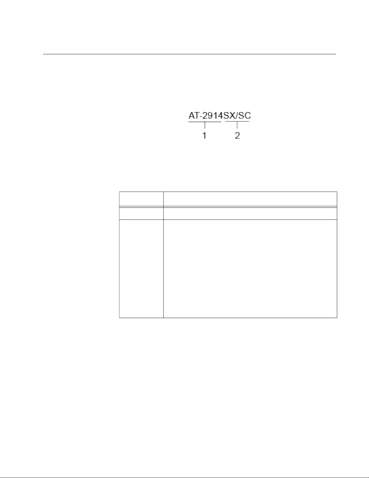
Model Naming Conventions
The hardware features of the 2914 series network adapters are
represented by the letters and numbers in the model names. The
conventions for the 2914 series network adapters are identified in
Figure 9.
The conventions are defined in Table 3.
Chapter 1: Introduction
Figure 9. 2914 Series Model Naming Conventions
.
Table 3. 2914 Series Model Naming Conventions
Convention Definition
1 Indicates the product name
2 Identifies the type of the port. The following is a list of
options:
SX/SC - port of 1000BASE-SX (short haul) fiber
optic cable with a duplex SC connector
SX/LC - port of 1000BASE-SX (short haul) fiber
optic cable with a duplex LC connector
SP - SFP slot
GP/SP - PoE-capable copper port and an SFP slot
PSU - power supply unit for the PoE-capable
copper port
23
Page 24

2914 Series Fiber Network Adapters with WoL Installation and User’s Guide
Supported Operating Systems
The following list shows the supported operating systems:
Windows 10 in 64-bit; Microsoft certified
Linux 2.6/3.x
The 2914 series network adapter that is installed on Linux systems uses
Linux inbox driver software to operate so that you do not need to install
driver software for Linux systems. A driver supplied with an operating
system is called an inbox driver.
For the Windows platforms, you must install driver software for the
network adapters. See Chapter 3, “Installing the Driver Software” on page
43.
24
Page 25

Accessing Documents
Documents for the 2914 series network adapters are available at the Allied
Telesis websites.
To access documents for 2914 series network adapters, do the following:
1. Open a web browser, such as Internet Explorer or FireFox, on your
2. Enter “2914” in the search box and press the enter key.
3. Click “2914 Series” from the search results.
Chapter 1: Introduction
system and enter the following:
http://www.alliedtelesis.com/
The Allied Telesis home page is displayed.
The 2914 series product page is displayed.
4. Click one of the listed documents.
The content of the document is displayed.
25
Page 26

2914 Series Fiber Network Adapters with WoL Installation and User’s Guide
Contents of Your Shipment
The following items are Included with your network adapter:
Antistatic bag
The network adapter is shipped in an antistatic bag. It protects the
network adapter when stored or shipped. Keep the network adapter in
its packaging until ready for installation.
Standard-profile bracket
The standard-profile bracket is longer than the low-profile bracket. The
2914 series network adapters are shipped with a low-profile bracket
attached.
Note
The driver software for Windows platforms is from the Allied Telesis
website. See Chapter 3, “Downloading the Driver Software” on page
45.
Inform your network equipment supplier of any missing or damaged items.
If you need to return the module, you must pack it in the original (or
equivalent) packing material or the warranty will be voided. See
“Contacting Allied Telesis” on page 13.
26
Page 27

Warranty Registration
Allied Telesis hardware products are covered under limited warranties.
All Allied Telesis warranties are subject to and provided only on the terms
and conditions set out in the Allied Telesis. For more information, visit the
Allied Telesis website at:
https://www.alliedtelesis.com/en/support/maintenance-and-warranty.
Chapter 1: Introduction
27
Page 28

2914 Series Fiber Network Adapters with WoL Installation and User’s Guide
28
Page 29

Chapter 2
Installing the Hardware
This chapter contains the following sections:
“System Requirements” on page 30
“Reviewing Safety Precautions” on page 31
“Pre-Installation Checklist” on page 33
“Replacing the Bracket” on page 34
“Installing a Network Adapter” on page 36
“Connecting the AT-2914GP-PSU Power Cord to the AT-2914GP/SP
Network Adapter” on page 40
“Connecting the Network Cables” on page 41
29
Page 30

2914 Series Fiber Network Adapters with WoL Installation and User’s Guide
System Requirements
Before installing the 2914 series network adapter, make sure your system
meets the requirements listed below:
PC with one of the following operating systems:
– Windows 10 in 64-bit; Microsoft certified
– Linux 2.6/3.x
One open PCIe slot
128 MB RAM (minimum)
30
Page 31

Reviewing Safety Precautions
Review the following safety precautions before you begin to install a
network adapter.
Note
The
indicates that a translation of the safety statement is
available in a PDF document titled “Translated Safety Statements”
posted on the Allied Telesis website at www.alliedtelesis.com/
support/software/.
Warning
Do not stare into the laser beam. L2
Warning
The fiber optic ports contain a Class 1 laser device. When the ports
are disconnected, always cover them with the provided plug.
Exposed ports may cause skin or eye damage. L4
Chapter 2: Installing the Hardware
Warning
Do not look directly at the fiber optic cable ends or inspect the cable
ends with an optical lens. L6
Warning
Do not work on this equipment or cables during periods of lightning
activity. E2
Warning
Operating Temperature: This product is designed for a maximum
ambient temperature of 50 degrees C. E7
Note
All Countries: Install this product in accordance with local and
National Electric Codes. E8
31
Page 32

2914 Series Fiber Network Adapters with WoL Installation and User’s Guide
Warning
The module is being installed in a system that operates with
voltages that can be lethal. Before you remove the cover of your
system, you must observe the following precautions to protect
yourself and to prevent damage to the system components.
– Remove any metallic objects or jewelry from your hands and
wrists.
– Make sure to use only insulated or nonconducting tools.
– Verify that the system is powered OFF and unplugged before
accessing internal components.
– Installation or removal of modules must be performed in a static-
free environment. The use of a properly grounded wrist strap or
other personal antistatic devices and an antistatic mat is strongly
recommended. E39
Caution
Do not use excessive force when seating the card, as the force may
damage the system or the adapter card. If the card resists seating,
remove it from the system, realign it, and try again. E47
32
Page 33

Pre-Installation Checklist
Before installing the 2914 series network adapter, check the following list:
1. Check that your computer has an appropriate open PCIe slot.
2. Verify that your system is using the latest BIOS.
3. When you download the driver software from the Allied Telesis
website, record the path to where the driver file resides on your
system.
4. If your system is active, shut it down.
5. When system shutdown is complete, power OFF and unplug your
system.
6. Holding the adapter card by the edges, remove it from its shipping
package and place it on an antistatic surface.
Chapter 2: Installing the Hardware
7. Check the adapter for visible signs of damage, particularly on the
card’s edge connector.
Note
Do not attempt to install a damaged adapter card. If the adapter card
is damaged, report it to Allied Telesis. See “Contacting Allied
Telesis” on page 13.
33
Page 34

2914 Series Fiber Network Adapters with WoL Installation and User’s Guide
Replacing the Bracket
The 2914 series network adapter is shipped with the low-profile bracket
attached to the adapter. Depending on your system, you may need to
replace the bracket with the standard bracket.
The following procedure describes how to remove the low-profile bracket
from the network adapter and replace it with the standard bracket. You
can also use this procedure to remove the standard bracket and replace it
with the low-profile bracket.
To replace the low-profile bracket with the standard bracket, perform the
following procedure:
1. Remove the screws that attach the bracket to the network adapter.
See Figure 10.
34
Figure 10. Removing the Low-Profile Bracket
2. Align the tabs of the standard bracket with the holes on the network
adapter and fasten the screws onto the network adapter. See Figure
11 on page 35.
Page 35

Chapter 2: Installing the Hardware
Figure 11. Installing the Standard Bracket
35
Page 36

2914 Series Fiber Network Adapters with WoL Installation and User’s Guide
Installing a Network Adapter
The following instructions apply to installing a 2914 series network adapter
in most systems. Refer to the manuals that were supplied with your
system for details about performing these tasks on your particular system.
To install the network adapter, perform the following procedure:
1. Review the “Pre-Installation Checklist” on page 33 and “Reviewing
Safety Precautions” on page 31.
Before installing the network adapter, ensure the system power is OFF
and unplugged from the power outlet, and that proper electrical
grounding procedures have been followed.
Warning
The module is being installed in a system that operates with
voltages that can be lethal. Before you remove the cover of your
system, you must observe the following precautions to protect
yourself and to prevent damage to the system components.
– Remove any metallic objects or jewelry from your hands and
wrists.
– Make sure to use only insulated or nonconducting tools.
– Verify that the system is powered OFF and unplugged before
accessing internal components.
– Installation or removal of modules must be performed in a static-
free environment. The use of a properly grounded wrist strap or
other personal antistatic devices and an antistatic mat is strongly
recommended. E39
2. Remove the system cover and select any empty PCIe slot. See Figure
12 on page 37.
If you do not know how to identify a PCIe slot, see your system
documentation.
36
Page 37

Chapter 2: Installing the Hardware
Figure 12. Removing the PC Cover
3. Select an empty, non-shared PCIe slot and remove the faceplate.
Keep the faceplate in a safe place. You may need it for future use. See
Figure 13.
Figure 13. Removing the Faceplate From PCIe Slot
4. Remove the network adapter from the shipping package and store the
packaging material in a safe location.
5. Applying even pressure at both corners of the network adapter, push
the adapter until it is firmly seated in the PCIe slot.
Make sure the adapter is securely seated. See Figure 14 on page 38.
37
Page 38

2914 Series Fiber Network Adapters with WoL Installation and User’s Guide
Figure 14. Inserting the Network Adapter
Caution
Do not use excessive force when seating the adapter, as the force
may damage the system or the adapter. If the adapter resists
seating, remove it from the system, realign it, and try again. E47
6. Secure the network adapter to the chassis with a Phillips-head screw
(not provided) as shown in Figure 15.
Figure 15. Securing the Network Adapter
7. Replace the system’s cover and secure it with the screws removed in
step 2.
38
8. Disconnect any personal antistatic devices.
9. Power the system on.
Page 39

Chapter 2: Installing the Hardware
Next, connect the network cables. See “Connecting the Network Cables”
on page 41.
39
Page 40

2914 Series Fiber Network Adapters with WoL Installation and User’s Guide
Connecting the AT-2914GP-PSU Power Cord to the AT-2914GP/SP
Network Adapter
Using the AT-2914GP-PSU power supply unit, the adapter can provide a
PD connected to the adapter through the copper port up to 25.5W of
power. In addition to providing more power to the PD, the adapter allows
communications even when the system is powered off.
Without the AT-2914GP-PSU power supply unit, the AT-2914GP/SP
adapter provides the PD with limited power, depending on the capability of
the system's PCIe 12V power rail. It is typically 10-15W; however, verify
your system's specifications and derate by 20% for planning purposes.
To connect the AT-2914GP-PSU power supply unit to the AT-2914GP/SP
adapter, perform the following procedures:
1. Make sure that the AT-2914GP/SP network adapter is installed in your
system properly.
To install the AT-2914GP/SP network adapter, see “Installing a
Network Adapter” on page 36.
2. Insert the AT-2914GP-PSU power cord connector to the front panel of
the AT-2914GP/SP network adapter and turn the connector clockwise.
See Figure 16.
Figure 16. Connecting Power Cord to the Network Adapter
40
3. Connect the other side of the power cord to an appropriate AC power
source.
The AT-2914GP/SP adapter starts using the AC power source to
provide power to a connected PD.
Page 41

Connecting the Network Cables
The 2914 series network adapter is equipped with a fiber optic port. To
connect the network adapter to the network, you must have a fiber optic
cable with the appropriate connector.
Chapter 2: Installing the Hardware
Connecting a
Fiber Optic
Network Cable
To connect a fiber optic network cable to the network adapter, perform the
following procedure:
1. Prepare a fiber optic cable with an appropriate connector.
Warning
The fiber optic ports contain a Class 1 laser device. When the ports
are disconnected, always cover them with the provided plug.
Exposed ports may cause skin or eye damage. L4
2. Remove a rubber plug from the network adapter.
3. Connect one end of the cable to the network adapter.
4. Connect the other end of the cable to the appropriate Ethernet network
port.
After the system is connected to the network and power is supplied,
the network adapter attempts to negotiate duplex and flow control via
the auto-negotiation protocol. If the link partner does not support Autonegotiation, the network adapter bypasses the process and attempts to
establish a link at 1000Mbps in full duplex.
Connecting an
SFP Transceiver
Note
After the cable is properly connected at both ends, the adapter card
LED should be functional. See Table 1 on page 18 for a description
of LED operation.
The AT-2914SP and AT-2914GP/SP network adapters require an SFP
transceiver and an appropriate cable to connect to the network.
1. Insert an SFP transceiver into the SFP slot on the network adapter
until the SFP transceiver snaps into place in the slot.
2. Remove the plug from the SFP transceiver.
3. Connect one end of the cable to the SFP transceiver.
4. Connect the other end of the cable to the appropriate Ethernet network
port or an appropriate port.
41
Page 42

2914 Series Fiber Network Adapters with WoL Installation and User’s Guide
After the system is connected to the network and power is supplied, the
network adapter attempts to establish the connection as follow:
With a Gigabit SFP, the network adapter attempts to negotiate
duplex and flow control via the Clause 37 Auto-Negotiation
protocol. If the link partner does not support Auto-negotiation, the
network adapter bypasses the process and attempts to establish a
link at 1000Mbps in full duplex.
With a 100Mbps SFP, the network adapter attempts to establish
the connection at 100Mbps in full-duplex.
42
Page 43

Chapter 3
Installing the Driver Software
This chapter describes how to install driver software for the 2914 series
network adapter onto your Windows platform. It contains the following
topics:
“Overview” on page 44
“Downloading the Driver Software” on page 45
“Accessing the Device Manager” on page 48
“Installing the Driver Software” on page 49
“Updating the Driver Software” on page 52
“Performing the Silent Installation” on page 53
43
Page 44

2914 Series Fiber Network Adapters with WoL Installation and User’s Guide
Overview
When you install the 2914 series network adapter in your computer, your
next step is to install driver software onto your Windows operating system.
You can install driver software using the Device Manager or the silent
installation method.
The Device Manager guides you through the installation process. The
silent installation method suppresses dialog boxes.
Guidelines Here are the guidelines for installing and updating the driver software on
your operating system:
To install or update the driver software, you must have
administrative privileges.
When you install the 2914 series network adapter on your
computer and start the system, it detects a new adapter and
installs a default Broadcom driver. If your system has another
Allied Telesis network adapter previously installed, the system
installs the Allied Telesis driver that resides in your system instead
of the default Broadcom driver.
Installing the
Driver Using
Device Manager
Installing the
Driver Using the
Silent Installation
Method
In either case, you must update the driver software for the 2914
series network adapter. See “Installing the Driver Using Device
Manager”, or “Installing the Driver Using the Silent Installation
Method”.
To install or update the driver software using the Device Manager, follow
the steps below:
“Downloading the Driver Software” on page 45
“Accessing the Device Manager” on page 48
“Installing the Driver Software” on page 49
Or
“Updating the Driver Software” on page 52
To install or update the driver software using the silent installation, follow
the steps below:
“Downloading the Driver Software” on page 45
“Performing the Silent Installation” on page 53
44
Page 45

Downloading the Driver Software
The driver for network adapters are available from the Allied Telesis
website.
To download the driver software, do the following:
1. Open a web browser, such as Internet Explorer or FireFox, on your
system and enter the following:
http://www.alliedtelesis.com/support/software
The Software Downloads page is displayed as shown in Figure 17.
.
Chapter 3: Installing the Driver Software
Figure 17. Software Downloads Page
45
Page 46

2914 Series Fiber Network Adapters with WoL Installation and User’s Guide
2. If you do not have an account for the Download center, fill the fields
and click Request Guest Access.
You will receive a guest login account and password via email.
3. Click Download Center.
The Login page is displayed. See Figure 18.
.
Figure 18. Login Page
4. Enter your account and password to login.
The Download Central Home page is displayed. See Figure 19.
.
46
Figure 19. Download Central Home Page
Page 47

Chapter 3: Installing the Driver Software
5. Select Product Search from the menu on the left bar as shown in
Figure 19 on page 46.
6. Enter “2914” in the search box and click Search.
The link to the driver for the 2914 products is listed.
7. Select the link.
8. Save the zip folder onto your system.
9. Right-click the zip folder and select Extract All.
10. Specify the location of the folder and click Extract.
11. Record the location of the folder.
47
Page 48

2914 Series Fiber Network Adapters with WoL Installation and User’s Guide
Accessing the Device Manager
To install or update the driver software for 2914 series network adapter,
you must first access Device Manager.
To access the Device Manager on your Windows 10 operating system,
perform the following:
1. Right-click the bottom left corner.
The Quick Access Menu appears.
2. Select Device Manager.
The Device Manager window appears as shown in Figure 20.
48
Figure 20. Device Manager on Windows Operating System
Page 49

Installing the Driver Software
To install the driver software, do the following:
Note
To install the driver software, you must have administrative
privileges.
1. Access the Device Manager. see “Accessing the Device Manager” on
page 48.
2. In the Device Manager window, double-click Network Adapters to
expand the field.
3. Right-click Allied Telesis AT-2914 Series Fiber Ethernet.
Note
The Device Manager may list your adapter as a Broadcom device,
or Allied Telesis device, depending on what drivers reside on your
system.
Chapter 3: Installing the Driver Software
The shortcut menu appears. See Figure 21 as an example.
Figure 21. Selecting the 2914 Series Adapter in Device Manager
4. Select Update Driver Software.
The Update Driver Software window pops up. See Figure 22 as an
example.
49
Page 50

2914 Series Fiber Network Adapters with WoL Installation and User’s Guide
Figure 22. Update Driver Software Window
5. Select Browse my computer for driver software.
The Update Driver Software window prompts you to enter the location
of the driver folder. See Figure 23 as an example.
50
Figure 23. Update Driver Software Window
6. Specify the location of the driver software. See “Downloading the
Driver Software” on page 45 for details.
7. Click Next.
Page 51

Chapter 3: Installing the Driver Software
The confirmation message shown in Figure 24 appears when the
driver software is successfully updated.
Figure 24. Update Driver Software Window Confirmation
8. Click Close.
51
Page 52

2914 Series Fiber Network Adapters with WoL Installation and User’s Guide
Updating the Driver Software
If your operating system automatically installs a default driver or
Broadcom driver, you need to update the driver software with the driver
that you downloaded from the Allied Telesis website. To obtain the latest
version of the AT-2914 network adapter driver, see “Downloading the
Driver Software” on page 45.
To update the driver software, you use the same procedure for installing
the driver software for the first time. The only difference between updating
and installing the driver software is the name of your adapter that Device
Manager detects and lists.
Device Manager lists your adapter card entry as Allied Telesis AT-2914
Series Fiber Ethernet once you installed the driver software. Before you
installed the driver software, Device Manager may list your adapter entry
as an Ethernet Controller, Broadcom NetXtreme device, or Allied Telesis
device.
To update the driver software for your AT-2914 network adapter, see
“Installing the Driver Software” on page 49.
52
Page 53

Performing the Silent Installation
To simplify the driver installation process, you may perform a silent
installation. The silent installation is a method of installing software in the
silent mode without constant interactions by suppressing dialog boxes.
Note
You can apply the silent installation method only to Microsoft
certified drivers. The drivers that Allied Telesis provides for the AT2914 network adapters are all Microsoft certified.
Use a command line utility called Driver package Installer (DPInst) for the
silent installation. DPInst is included in the Windows Developer Kit (WDK)
provided by Microsoft. You can obtain the latest DPInst by downloading
and installing the latest WDK from the Microsoft website.
Chapter 3: Installing the Driver Software
Installing the
Driver Silently
To install the driver silently, perform the following instructions:
1. Create a folder in your Windows system.
2. Download driver software for the AT-2914 network adapter.
See “Downloading the Driver Software” on page 45.
3. Place the driver files that you downloaded into the folder that you
created in step 1.
The folder should include the following driver files:
– .sys
– .inf
– .cat
4. Download the latest WDK to obtain the dpinst utility.
Consult the Microsoft websites to download WDK.
5. Place the dpinst.exe and its supporting files in the same folder
where you placed the driver files.
You must place the 64-bit dpinst utility if your operating system is the
64-bit version. Place the 32-bit for dpinst utility for the 32-bit version
operating system.
6. Open a command prompt window with administrator privileges.
7. Change the directory to the folder where the dpinst utility and the
driver files reside.
53
Page 54

2914 Series Fiber Network Adapters with WoL Installation and User’s Guide
8. Install the driver in the silent mode by entering the following command:
> dpinst /S
Note
Adding the /S switch to the dpinst command suppresses the
display of wizard pages, user dialog boxes, and other user
intervention requests.
The driver is installed silently.
Viewing
Supported
DPInst Options
You can display help information about the dpinst command-line
options.
View all supported dpinst options by executing the following command:
1. Open a command prompt window with administrator privileges.
2. Change the directory to the folder where the dpinst utility and the
driver files reside.
> dpinst /?
The command displays the help text.
54
Page 55

Chapter 4
Configuring the VLAN and Priority
This chapter describes how to access the CLI on the AT-2914GP/SP
network adapter and change the VLAN and priority settings.
It contains the following topics:
“Overview” on page 56
“Accessing the CLI on the AT-2914GP/SP Network Adapter” on
page 57
“Configuring the VLAN and Priority Settings on the Network Adapter”
on page 60
Note
This chapter only applies to the AT-2914GP/SP model.
55
Page 56

2914 Series Fiber Network Adapters with WoL Installation and User’s Guide
Overview
The AT-2914GP/SP network adapter has an internal CLI for you to modify
the VLAN and priority settings through the Console port. To access the
CLI, connect the adapter to your management PC and install a virtual
serial port driver. After the driver is installed, you can access the CLI to
modify the VLAN and priority settings using a terminal emulator program,
such as Putty or TeraTerm, on the management PC.
.
Figure 25. Accessing the CLI on the Adapter through the Console Port
Note
A management PC can be the PC that the AT-2914GP/SP adapter
is installed on.
To access the CLI to modify the VLAN and priority settings, perform the
following procedures:
“Accessing the CLI on the AT-2914GP/SP Network Adapter” on
page 57
“Configuring the VLAN and Priority Settings on the Network
Adapter” on page 60
56
Page 57

Chapter 4: Configuring the VLAN and Priority
Accessing the CLI on the AT-2914GP/SP Network Adapter
To modify VLAN and Priority settings on the AT-2914GP/SP adapter, you
must access the CLI on the adapter.
Guidelines Here are the guidelines for modifying the VLAN and priority settings of
AT-2914GP/SP adapter by accessing the CLI:
To install or update serial port driver software, you must have
administrative privileges.
The Console port of the adapter is a USB Micro-B receptacle.
What to Prepare Here is a list of items that you need to provide:
A cable with a USB-A connector and USB Micro-B connector
A management PC with a terminal emulator program, such as
TeraTerm or Putty, installed
Accessing the
CLI on the
Adapter for the
First Time
Note
A management PC can be the PC that the AT-2914GP/SP adapter
is installed on.
To connect the AT-2914GP/SP adapter to a PC, perform the following
procedures:
1. Connect the USB-A connector of the cable to the USB-A receptacle on
a management PC.
2. Connect the other end of the cable, USB Micro-B connector, to the
USB Micro-B receptacle on the AT-2914GP/SP adapter.
If the management PC is connected to the Internet, the serial port
driver is automatically installed onto the laptop or PC.
If the management PC is not connected to the Internet, go to “Installing
the Serial Port Driver Manually” on page 58 to download and install the
driver.
3. Open the Device Manger on the management PC and expand the
“Ports (COM & LTP)” tree.
You see a Silicon Labs CP210x USB to UART Bridge (COMn) in the
COM ports list as shown in Figure 26 on page 58.
4. Note the COM number (COMn).
You need the COM number for the terminal emulator program when
accessing the CLI.
57
Page 58

2914 Series Fiber Network Adapters with WoL Installation and User’s Guide
.
Installing the
Serial Port Driver
Manually
Figure 26. COM Ports In the Device Manager
5. If you do not see a Silicon Lab device in the list, the serial port driver
installation failed. Go to “Installing the Serial Port Driver Manually” on
page 58 to download and install the driver.
To download and install the serial port driver to the management laptop or
PC, perform the following:
1. Go to SILISON LABS’s website:
www.silabs.com/products/development-tools/software/usb-touart-bridge-vcp-drivers
2. Download driver software for your Windows version.
The zip files are downloaded.
3. Unzip the zip files.
4. Find an appropriate executable and click it.
5. Follow the instructions to complete the installation.
58
6. Open the Device Manger on the laptop or PC and expand the “Ports
(COM & LTP)” tree.
You see the Silicon Lab device in the COM ports list.
Page 59

Chapter 4: Configuring the VLAN and Priority
Accessing the
CLI Using a
Terminal
Emulator
Program
To access the CLI on the adapter to modify VLAN and priority settings,
perform the following procedure:
1. Connect the USB-A connector of the cable to the USB-A receptacle on
a management PC.
2. Connect the other end of the cable, USB Micro-B connector, to the
USB Micro-B receptacle on the AT-2914GP/SP adapter.
3. Start the terminal emulator program with the COM number that you
noted from Device Manager.
4. Configure the terminal emulator program as follows:
Baud rate: 115200
Data bit: 8
Stop bit 1:
Parity: None
Flow control: None
5. Press Enter on the terminal emulator program on the management PC.
The VLAN and Priority configuration menu is displayed as shown in
Figure 27.
.
Figure 27. VLAN and Priority Configuration Window
6. To configure the VLAN and Priority settings, go to “Configuring the
VLAN and Priority Settings on the Network Adapter” on page 60.
59
Page 60

2914 Series Fiber Network Adapters with WoL Installation and User’s Guide
Configuring the VLAN and Priority Settings on the Network Adapter
You can specify or modify the VLAN and Priority settings on the
AT-2914GP/SP adapter through the CLI. See Table 4.
Table 4. VLAN and Priority Settings
Item Description
Device name Displays the network adapter name.
FW Displays the current console firmware revision.
VLAN and Priority Settings:
VLAN Tagging Displays the current tagging status. The options
are enabled or disabled. The default is disabled.
PoE VID Displays the VLAN ID for the PoE copper port. The
default is 0. The range is 0 to 4095.
PoE QoS Displays QoS priority level for the PoE copper port.
The default is 0. The range is 0 to 7.
PC VID Displays the VLAN ID for the PC traffic. The default
is 0.
PC QoS Displays the QoS priority level for the PC traffic.
The default is 0.
VLAN and Priority Setting Commands:
1 Enable VLAN tagging.
2 Disable VLAN tagging.
3 Change the VLAN ID for the PoE copper port.
4 Change the QoS priority level for the PoE copper
port.
5 Change the VLAN ID for the PC traffic.
6 Change the QoS priority level for the PC traffic.
7 Saves and Applies the VLAN settings.
60
Page 61

Chapter 4: Configuring the VLAN and Priority
Enabling the
VLAN Tagging
When the VLAN tagging is enabled on the adapter, VLAN and Priority tags
are added to Ethernet frames.
Note
Make sure that the Priority & VLAN setting in the Advanced
Properties is disabled. To see and disable the setting, see “Priority &
VLAN” on page 86.
To enable the VLAN tagging, perform the following procedure:
1. Enter 1 at the Console prompt:
>> 1
A “VLAN Enabled” prompt is displayed.
2. Press Enter to continue.
The “please apply settings” prompt is displayed to indicate changes
have been made but not yet applied.
3. Enter 7 at the Console prompt to apply the change:
Disabling the
VLAN Tagging
>> 7
VLAN Configuration Applied prompt is displayed.
4. Press Enter to continue.
When the VLAN tagging is disabled on the adapter, no VLAN and Priority
tags are added.
To disable the VLAN tagging, perform the following procedure:
1. Enter 2 at the Console prompt:
>> 2
A “VLAN Disabled” prompt is displayed.
2. Press Enter to continue.
The “please apply settings” prompt is displayed to indicate changes
have been made but not yet applied.
3. Enter 7 at the Console prompt to apply the change:
>> 7
A “NIC must be REMOVED to disable VLAN” prompt is displayed.
4. Press Enter to continue.
61
Page 62

2914 Series Fiber Network Adapters with WoL Installation and User’s Guide
5. Close the serial console and power down the system.
6. Remove and re-install the AT-2914GP/SP network adapter.
7. Power on the system.
The VLAN Tagging is now disabled.
Changing the
VLAN ID for the
PoE Copper Port
You can specify the VLAN ID for the PoE copper port. The default setting
is 0.
To specify the PoE VID, perform the following procedure:
1. Enter 3 at the Console prompt:
>> 3
A “New VID (decimal)” prompt is displayed.
2. Enter the new VID and press Enter.
The “please apply settings” prompt is displayed to indicate changes
have been made but not yet applied.
3. Enter 7 at the Console prompt to apply the new setting:
>> 7
VLAN Configuration Applied prompt is displayed.
4. Press Enter to continue.
Changing the
QoS Priority
Level for the PoE
Copper Port
62
You can specify the QoS priority level for the PoE copper port. The default
setting is 0.
To specify the PoE VID, perform the following procedure:
1. Enter 4 at the Console prompt:
>> 4
A “New QoS (decimal)” prompt is displayed.
2. Enter the new QoS priority level and press Enter.
The “please apply settings” prompt is displayed to indicate changes
have been made but not yet applied.
3. Enter 7 at the Console prompt to apply the new setting:
>> 7
VLAN Configuration Applied prompt is displayed.
Page 63

4. Press Enter to continue.
Chapter 4: Configuring the VLAN and Priority
Changing the
VLAN ID for the
PC Traffic
Changing the
QoS Priority
Level for the PC
Traffic
You can specify the VLAN ID for the PC traffic. The default setting is 0.
To specify the VLAN ID for the PC traffic, perform the following procedure:
1. Enter 5 at the Console prompt:
>> 5
A “New VID (decimal)” prompt is displayed.
2. Enter the new VID and press Enter.
The “please apply settings” prompt is displayed to indicate changes
have been made but not yet applied.
3. Enter 7 at the Console prompt to apply the new setting:
>> 7
VLAN Configuration Applied prompt is displayed.
4. Press Enter to continue.
You can specify the QoS priority level for the PC traffic. The default setting
is 0.
To specify the QoS priority level for the PC traffic, perform the following
procedure:
1. Enter 6 at the Console prompt:
>> 6
A “New QoS (decimal)” prompt is displayed.
2. Enter the new QoS priority level and press Enter.
The “please apply settings” prompt is displayed to indicate changes
have been made but not yet applied.
3. Enter 7 at the Console prompt to apply the new setting:
>> 7
VLAN Configuration Applied prompt is displayed.
4. Press Enter to continue.
63
Page 64

2914 Series Fiber Network Adapters with WoL Installation and User’s Guide
64
Page 65

Chapter 5
Configuring a VoIP Phone System
This chapter describes how to configure a VoIP phone system using the
AT-2914GP/SP network adapter. It contains the following topics:
“Overview” on page 66
“Configuring VLAN Tagging on Adapter Ports” on page 67
65
Page 66

2914 Series Fiber Network Adapters with WoL Installation and User’s Guide
Overview
The AT-2914GP/SP network adapter is installed on a PC and connects
the PC to the Ethernet network through the fiber optic port and a Powered
Device (PD) through the PoE+ copper port. A PD is a device powered
through an Ethernet cable by a Power Supply Equipment (PSE). A PC
with the AT-2914GP/SP network adapter is a PSE; a VoIP phone, Wi-Fi
access point, and security camera are PD’s.
Figure 28 illustrates the configuration of the PC’s and VoIP phones as an
example using the AT-2914GP/SP network adapters.
.
Figure 28. VoIP Phone Configuration Example
When you connect VoIP phones to your network through PCs, you should
separate voice traffic from data traffic using VLAN because voice traffic
must have higher priority over other types of traffic.
When VLAN’s are enabled and configured, incoming traffic on the fiber
link are routed to the copper port or the PC, depending on the VLAN ID in
the frames. Tagged frames with unmatched VLAN ID and untagged
frames are discarded. Outbound traffic from the PC and VoIP phone are
sent to the switch on the fiber link.
In the Figure 28, you assign the VLAN ID 150 and QoS 5 to VoIP voice
traffic from the copper port and the VLAN ID 10 and QoS 0 to the PC
traffic. The voice traffic has the higher priority (QoS 5) than the PC traffic
(QoS 0).
When frames from the copper port does not have a VLAN ID assigned,
these frames remain untagged when they arrive at the switch. For more
tagging examples, See “Configuring VLAN Tagging on Adapter Ports” on
page 67.
To assign a VLAN ID and priority for the PC traffic and traffic from the
copper port, see Chapter 4, “Configuring the VLAN and Priority” on page
55.
66
Page 67

Configuring VLAN Tagging on Adapter Ports
To separate voice traffic coming from the VoIP phone from data traffic
from the PC, several combinations of VLAN tagging settings are possible.
Chapter 5: Configuring a VoIP Phone System
VLAN Tagging
Combinations
Figure 29 illustrates possible VLAN tagging combinations. In this example,
voice frames belong to the VLAN 150 and data frames belong to the VLAN
10 except Config. 3.
.
Figure 29. VoIP Phone Tagging Example
Table 5 shows VLAN tagging combinations.
Table 5. VLAN Tagging Combinations
Config. 1 Config. 2 Config. 3
VoIP Phone VLAN tag (VID: 150)
(In Phone Setting)
VoIP Data Traffic
-
Untagged
or
VLAN tag (VID: 10)
PC Data Traffic
(Set VID in the
Advanced Properties.
See “VLAN ID” on
page 95.)
- -
VLAN tag (VID: 150)
(Set using the
adapter’s CLI)
VLAN tag (VID: 10)
(Set using the
adapter’s CLI)
Untagged
Untagged
67
Page 68

2914 Series Fiber Network Adapters with WoL Installation and User’s Guide
Using
VLAN-Capable
VoIP Phones to
Set VLAN
Using
AT-2914GP/SP to
Set VLAN
Non-VLAN
Application
Some VoIP phones are capable of VLAN tagging. In Config 1 using a
VLAN-capable VoIP phone, you may assign the VLAN ID 150 using the
VoIP phone setting. Voice frames get the VLAN tagged at the phone, are
sent to the copper port and transmitted to the switch through the fiber port.
The voice frames and VLAN tags are unchanged by the AT-2914GP/SP
adapter.
You can assign a VLAN ID to the PC traffic using the adapter’s Advanced
Properties; however, when voice frames are tagged at the VoIP phone, do
not enable VLAN via the AT-2914GP/SP adapter’s CLI.
Config 2 is a configuration when a VoIP phone is not capable of VLAN
tagging, or you prefer to set up VLAN's at the network adapter. You can
assign the VLAN ID 150 to the copper port via the adapter’s CLI. Voice
frames from the VoIP phone get tagged when they arrive at the copper
port and are sent to the switch through the fiber optic port. The voice
frames are unchanged by the AT-2914GP/SP adapter. The VLAN ID 10 is
added to PC traffic as they are sent out the fiber link.
You can leave the PC traffic and traffic from the VoIP phone untagged as
with Config 3.
68
Page 69

Chapter 6
Modifying Advanced Properties
This chapter includes the following topics:
“Overview” on page 70
“Accessing Advanced Properties” on page 71
“802.3az EEE” on page 72
“ARP Offload” on page 73
“Ethernet@WireSpeed” on page 74
“Flow Control” on page 75
“Interrupt Moderation” on page 77
“Jumbo Mtu” on page 78
“Large Send Offload v2 (IPv4)” on page 79
“Large Send Offload v2 (IPv6)” on page 80
“Maximum Number of RSS Queues” on page 81
“Network Address” on page 83
“NS Offload” on page 85
“Priority & VLAN” on page 86
“Receive Side Scaling” on page 88
“Speed & Duplex” on page 89
“TCP/UDP Checksum Offload (IPv4)” on page 91
“TCP/UDP Checksum Offload (IPv6)” on page 93
“VLAN ID” on page 95
“Wake on Magic Packet” on page 96
“Wake on Pattern Match” on page 97
“WOL Speed” on page 98
69
Page 70

2914 Series Fiber Network Adapters with WoL Installation and User’s Guide
Overview
The 2914 series network adapters allow you to modify advanced
properties to meet your requirements. To access the advanced properties,
access Device Manager, then go to each advanced property page.
Guidelines Here are the guidelines to modifying the advanced properties:
To change the advanced property settings, you must have
Administrator privileges.
When you upgrade the driver software, the settings of the
advanced properties may change. Verify the settings after
upgrading the driver software.
70
Page 71

Accessing Advanced Properties
To modify advanced properties, first access Device Manager, open the
properties of your adapter, and select a feature you want to change its
setting.
1. Access Device Manager. See “Accessing the Device Manager” on
page 48.
2. In the Device Manager window, double-click Allied Telesis AT-2914
Series Fiber Ethernet.
The properties window pops up.
3. Click the Advanced tab.
The Advanced Properties window opens as shown in Figure 30.
Chapter 6: Modifying Advanced Properties
Figure 30. Advanced Properties Window
71
Page 72

2914 Series Fiber Network Adapters with WoL Installation and User’s Guide
802.3az EEE
The 802.3az EEE (Energy Efficient Ethernet) property allows you to
optimize the energy usage of the interface over Ethernet.
Note
The setting is always disabled on the 2914 series adapter.
To view the 802.3az EEE feature, do the following:
1. Access the Advanced Properties.
See “Accessing Advanced Properties” on page 71.
2. Select 802.3az EEE in the Property box.
The 802.3az EEE page is displayed as shown in Figure 31.
72
Figure 31. 802.3az EEE Page
3. Click OK.
Page 73

ARP Offload
Chapter 6: Modifying Advanced Properties
The ARP Offload feature enables the adapter not to wake up when
responding to an ARP request. ARP is used to verify whether a computer
is still present on the network and resolve an IP address into a MAC
address.
To enable or disable the ARP Offload feature, do the following:
1. Access the Advanced Properties.
See “Accessing Advanced Properties” on page 71.
2. Select ARP Offload in the Property box.
The ARP Offload page is displayed as shown in Figure 32.
Figure 32. ARP Offload Page
3. Select one of the following options:
Disable — This feature is disabled.
Enable — The adapter does not wake up when responding to an
ARP request. This is the default setting.
4. Click OK.
73
Page 74

2914 Series Fiber Network Adapters with WoL Installation and User’s Guide
Ethernet@WireSpeed
The Ethernet@WireSpeed feature connects two devices even when the
devices are connected through an impaired copper cable.
Note
The setting is always disabled on the 2914 series adapter.
To view the Ethernet@WireSpeed setting, do the following:
1. Access the Advanced Properties.
See “Accessing Advanced Properties” on page 71.
2. Select Ethernet@WireSpeed in the Property box.
The Ethernet@WireSpeed page is displayed as shown in Figure 33.
74
Figure 33. Ethernet@WireSpeed Page
3. Click OK.
Page 75

Flow Control
Chapter 6: Modifying Advanced Properties
The Flow Control feature allows you to control the flow between the
AT-2914 adapter port and its link partner. You can enable or disable the
adapter port to process received PAUSE frames and transmit PAUSE
frames.
To enable or disable the Flow Control feature, do the following:
1. Access the Advanced Properties.
See “Accessing Advanced Properties” on page 71.
2. Select Flow Control in the Property box.
The Flow Control page is displayed as shown in Figure 34.
Figure 34. Flow Control Page
3. Select one of the following options if available:
Note
The options and default setting depend on your operating system
and the version of the driver that you installed.
Auto Negotiation — The setting of the Flow Control property is
determined during the auto-negotiation process.
Disabled — The adapter ignores PAUSE frames.
75
Page 76

2914 Series Fiber Network Adapters with WoL Installation and User’s Guide
Tx & Rx Enabled — The adapter processes ingress PAUSE
frames and transmits PAUSE frames.
Rx Enabled — The adapter processes ingress PAUSE frames,
but does not transmit PAUSE frames.
Tx Enabled — The adapter transmits PAUSE frames, but ignores
PAUSE frames when receiving.
4. Click OK.
76
Page 77

Interrupt Moderation
The Interrupt Moderation feature allows you to limit the rate of interrupts to
the CPU during packet transmission and packet reception. When this
feature is enabled, interrupts are handled as a group so that the CPU
utilization decreases; however, the latency may increase.
To enable or disable the Interrupt Moderation feature, do the following:
1. Access the Advanced Properties.
2. Select Interrupt Moderation in the Property box.
Chapter 6: Modifying Advanced Properties
See “Accessing Advanced Properties” on page 71.
The Interrupt Moderation page is displayed as shown in Figure 35.
Figure 35. Interrupt Moderation Page
3. Select one of the following options:
Disable — The Interrupt Moderation feature is disabled
Enable — The Interrupt Moderation feature is enabled. This is the
default setting.
4. Click OK.
77
Page 78

2914 Series Fiber Network Adapters with WoL Installation and User’s Guide
Jumbo Mtu
The Jumbo Mtu (Maximum transmission unit) feature allows you to specify
the maximum size of Ethernet frames that the adapter port supports. The
network performance usually improves when the larger frame size is
specified; however, the network must be capable of supporting the
oversized Ethernet frames.
To change the Jumbo Mtu setting, do the following:
1. Access the Advanced Properties.
See “Accessing Advanced Properties” on page 71.
2. Select Jumbo Mtu in the Property box.
The Jumbo Mtu page is displayed as shown in Figure 36.
78
Figure 36. Jumbo Mtu Page
3. Specify the size of the frame in the Value box.
The range of the value is from 1,500 to 9,000. The default value is
1,500.
4. Click OK.
Page 79

Large Send Offload v2 (IPv4)
The Large Send Offload v2 (IPv4) feature allows you to control the load of
sending out large packets. When this feature is enabled, the adapter port
segments large packets for IPv4 traffic and reduces the CPU load.
This feature, which supports large packets up to 256kb, overrides the
Large Send Offload (IPv4) feature if both features are enabled.
To enable or disable the Large Send Offload v2 (IPv4) feature, do the
following:
1. Access the Advanced Properties.
See “Accessing Advanced Properties” on page 71.
2. Select Large Send Offload v2 (IPv4) in the Property box.
The Large Send Offload v2 (IPv4) page is displayed as shown in
Figure 37.
Chapter 6: Modifying Advanced Properties
Figure 37. Large Send Offload v2 (IPv4) Page
3. Select one of the following options:
Disable — The feature is disabled.
Enable — The adapter port segments large packets up to 256kb
for IPv4 traffic before sending them out. This is the default setting.
4. Click OK.
79
Page 80

2914 Series Fiber Network Adapters with WoL Installation and User’s Guide
Large Send Offload v2 (IPv6)
The Large Send Offload v2 (IPv6) feature allows you to control the load of
sending out large packets. When this feature is enabled, the adapter port
segments large packets for IPv6 traffic and reduces the CPU load.
To enable or disable the Large Send Offload v2 (IPv6) feature, do the
following:
1. Access the Advanced Properties.
See “Accessing Advanced Properties” on page 71.
2. Select Large Send Offload v2 (IPv6) in the Property box.
The Large Send Offload v2 (IPv6) page is displayed as shown in
Figure 38.
80
Figure 38. Large Send Offload (IPv6) Page
3. Select one of the following options:
Disable — The adapter does not segment packets for IPv6 traffic.
Enable — The adapter port segments large packets up to 256kb
for IPv6 traffic before sending them out. This is the default setting.
4. Click OK.
Page 81

Maximum Number of RSS Queues
The RSS Queues feature assigns data to queues associated with physical
CPU cores. You can specify the maximum number of RSS queues that the
network adapter assigns receiving data to.
To specify or change the maximum number of RSS Queues, do the
following:
1. Access the Advanced Properties.
See “Accessing Advanced Properties” on page 71.
2. Select Maximum Number of RSS Queues in the Property box.
The Maximum Number of RSS Queues page is displayed as shown in
Figure 39.
Chapter 6: Modifying Advanced Properties
Figure 39. Maximum Number of RSS Queues Page
3. Select one of the following options:
Note
The supported number of RSS queues and default setting depend
on the network adapter and operation system. You might not see all
options listed below.
81
Page 82

2914 Series Fiber Network Adapters with WoL Installation and User’s Guide
RSS 4 Queues — The system allocates up to four RSS queues.
RSS 1 Queue — The system allocates up to one RSS queue.
RSS 2 Queue — The system allocates up to two RSS queues.
4. Click OK.
82
Page 83

Network Address
Chapter 6: Modifying Advanced Properties
The Network Address property allows you to replace the MAC address
originally assigned to the adapter with a user-defined address. The userdefined address that you assign to the adapter is called a locally
administered address.
Caution
A locally administered address overrides the original MAC address
stored in the hardware. When you change the MAC address, be
sure to assign a unique MAC address. E81
To assign or change the Network Address, do the following:
1. Access the Advanced Properties.
See “Accessing Advanced Properties” on page 71.
2. Select Network Address in the Property box.
The Network Address page is displayed as shown in Figure 40.
Figure 40. Network Address Page
83
Page 84

2914 Series Fiber Network Adapters with WoL Installation and User’s Guide
3. In the Value text box, enter a locally administered address for the
AT-2914 network adapter.
By default, no locally administered address is assigned.
Here are guidelines to assigning a locally administered address:
The address must be unique.
The address consists of a 12-digit hexadecimal number, for
example, “000C46005501.”
The range is from 0000 0000 0001 to FFFF FFFF FFFD excluding
multicast MAC addresses, which cannot be used. The multicast
MAC address has the least significant bit of the most significant
octet as 1.
4. Click OK.
84
Page 85

NS Offload
Chapter 6: Modifying Advanced Properties
The NS (Neighbor Solicitation) Offload feature enables the adapter not to
wake up when responding to an NS request.
To enable or disable the NS Offload feature, do the following:
1. Access the Advanced Properties.
See “Accessing Advanced Properties” on page 71.
2. Select NS Offload in the Property box.
The NS Offload page is displayed as shown in Figure 41.
Figure 41. NS Offload Page
3. Select one of the following options:
Disable — This feature is disabled.
Enable — The adapter does not wake up when responding to an
NS request. This is the default setting.
4. Click OK.
85
Page 86

2914 Series Fiber Network Adapters with WoL Installation and User’s Guide
Priority & VLAN
The Priority & VLAN feature allows you to control sending and receiving
tagged frames of QoS and VLAN.
When the property is set to Priority & VLAN Enabled, the adapter sends
and receives QoS and VLAN tagged frames; with Priority Enabled, the
adapter sends and receives QoS tagged frames; with VLAN Enabled,
the adapter sends and receives VLAN tagged frames. To assign a VLAN
ID to the adapter, see “VLAN ID” on page 95.
Note
The Priority & VLAN should always be disabled when you add VLAN
tags via the AT-2914GP/SP adapter’s CLI.
To enable or disable the Priority & VLAN feature, do the following:
1. Access the Advanced Properties.
See “Accessing Advanced Properties” on page 71.
2. Select Priority & VLAN in the Property box.
The Priority & VLAN page is displayed as shown in Figure 42.
86
Figure 42. Priority & VLAN Page
Page 87

Chapter 6: Modifying Advanced Properties
3. Select one of the following options:
Priority & VLAN Enabled — The adapter sends and receives
QoS and VLAN tagged frames. This is the default setting.
Priority & VLAN Disabled — The adapter does not send and
ignores QoS and VLAN tagged frames.
Note
Select this option when adding VLAN tags via the AT-2914GP/SP
adapter’s CLI.
Priority Enabled — The adapter sends and receives QoS tagged
frames.
VLAN Enabled — The adapter sends and receives VLAN tagged
frames.
4. Click OK.
87
Page 88

2914 Series Fiber Network Adapters with WoL Installation and User’s Guide
Receive Side Scaling
The Receive Side Scaling (RSS) feature allows the adapter to efficiently
distribute receive processing across multiple CPU’s and to prevent from
overloading a single CPU. To make this feature effective, the computer
must have multiple CPU’s in a multiprocessor system.
To enable or disable the Receive Side Scaling feature, do the following:
1. Access the Advanced Properties.
See “Accessing Advanced Properties” on page 71.
2. Select Receive Side Scaling in the Property box.
The Receive Side Scaling page is displayed as shown in Figure 43.
88
Figure 43. Receive Side Scaling Page
3. Select one of the following options:
Enable — Receiving data is processed by multiple CPU’s. This is
the default setting.
Disable — Receiving data is processed by a single CPU.
4. Click OK.
Page 89

Speed & Duplex
Chapter 6: Modifying Advanced Properties
The Speed & Duplex property is set to Auto-negotiation.
Note
The setting is always Auto-negotiation for the 2914 series adapter.
When the system is connected to the network and power is supplied, a
network adapter attempts as follows:
The AT-2914SX/SC and AT-2914SX/LC adapters attempt to
negotiate duplex and flow control. If the link partner does not
support Auto-negotiation, the network adapter bypasses the
process and attempts to establish at 1000Mbps in full duplex.
The AT-2914SP and AT-2914GP/SP adapters with a Gigabit SFP
transceiver attempt to negotiate duplex and flow control.If the link
partner does not support Auto-negotiation, the network adapter
bypasses the process and attempts to establish at 1000Mbps in full
duplex.
The AT-2914SP and AT-2914GP/SP adapters with a 100Mbps
SFP transceiver attempt to establish at 100Mbps in full duplex.
The copper port of the 2914GPSP adapter always auto-negotiates.
It supports 10/100/1000Base-T and negotiates with the link partner
to the highest common denominator.
To view the Speed & Duplex property, do the following:
1. Access the Advanced Properties.
See “Accessing Advanced Properties” on page 71.
2. Select Speed & Duplex in the Property box.
The Speed & Duplex page is displayed as shown in Figure 44 on page
90.
89
Page 90

2914 Series Fiber Network Adapters with WoL Installation and User’s Guide
3. Click OK.
Figure 44. Speed & Duplex Page
90
Page 91

TCP/UDP Checksum Offload (IPv4)
The TCP/UDP Checksum Offload (IPv4) function enables the adapter port
to compute the checksum of transmitting IPv4 packets and verify the
checksum of receiving IPv4 packets, taking load off from the CPU.
To modify the TCP/UDP Checksum Offload (IPv4) setting, do the
following:
1. Access the Device Manager on your operating system.
See “Accessing Advanced Properties” on page 71.
2. Select TCP/UDP Checksum Offload (IPv4) in the Property box.
The TCP/UDP Checksum Offload (IPv4) page is displayed as shown in
Figure 45.
Chapter 6: Modifying Advanced Properties
Figure 45. TCP/UDP Checksum Offload (IPv4) Page
3. Select one of the following options:
Rx & Tx Enabled — Enables the TCP/UDP Checksum Offload
(IPv4) function for both receiving and transmitting IPv4 packets.
This is the default setting.
Disabled — Disables the TCP/UDP Checksum Offload (IPv4)
function for both receiving and transmitting.
91
Page 92

2914 Series Fiber Network Adapters with WoL Installation and User’s Guide
Rx Enabled — Enables the TCP/UDP Checksum Offload (IPv4)
function only for receiving IPv4 packets.
Tx Enabled — Enables the TCP/UDP Checksum Offload (IPv4)
function only for transmitting IPv4 packets.
4. Click OK.
92
Page 93

TCP/UDP Checksum Offload (IPv6)
The TCP/UDP Checksum Offload (IPv6) function enables the adapter port
to compute the checksum of transmitting IPv6 packets and verify the
checksum of receiving IPv6 packets, taking load off from the CPU.
To enable or disable the TCP/UDP Checksum Offload (IPv6) feature, do
the following:
1. Access the Device Manager on your operating system.
See “Accessing Advanced Properties” on page 71.
2. Select TCP/UDP Checksum Offload (IPv6) in the Property box.
The TCP/UDP Checksum Offload (IPv6) page is displayed as shown in
Figure 46.
Chapter 6: Modifying Advanced Properties
Figure 46. TCP/UDP Checksum Offload (IPv6) Page
3. Select one of the following options:
Rx & Tx Enabled — Enables the TCP/UDP Checksum Offload
(IPv6) function for both receiving and transmitting IPv6 packets.
This is the default setting.
Disabled — Disables the TCP/UDP Checksum Offload (IPv6)
function for both receiving and transmitting.
93
Page 94

2914 Series Fiber Network Adapters with WoL Installation and User’s Guide
Rx Enabled — Enables the TCP/UDP Checksum Offload (IPv6)
function only for receiving IPv6 packets.
Tx Enabled — Enables the TCP/UDP Checksum Offload (IPv6)
function only for transmitting IPv6 packets.
4. Click OK.
94
Page 95

VLAN ID
Chapter 6: Modifying Advanced Properties
The VLAN ID property allows you to specify a VLAN ID on your network to
the adapter port. The adapter port adds the value of the VLAN ID to a
frame in the VLAN tag before transmitting the frame.
To change the VLAN ID value, do the following:
1. Access the Advanced Properties.
See “Accessing Advanced Properties” on page 71.
2. Select VLAN ID in the Property box.
The VLAN ID page is displayed as shown in Figure 47.
Figure 47. VLAN ID Page
3. Specify a VLAN ID in the Value box.
The range of the value is from 0 to 4094. The default value is 0.
4. Click OK.
95
Page 96

2914 Series Fiber Network Adapters with WoL Installation and User’s Guide
Wake on Magic Packet
The Wake on Magic Packet feature enables the adapter to wake up from a
low-power mode when the adapter port receives a Magic packet.
To enable or disable the Wake on Magic Packet feature, do the following:
1. Access the Advanced Properties.
See “Accessing Advanced Properties” on page 71.
2. Select Wake on Magic Packet in the Property box.
The Wake on Magic Packet page is displayed as shown in Figure 48.
96
Figure 48. Wake on Magic Packet Page
3. Select one of the following options:
Enable — The adapter wakes up from a low-power mode when
receiving a Magic Packet. This is the default setting.
Disable — The adapter stays in a low-power mode when receiving
a Magic Packet.
4. Click OK.
Page 97

Wake on Pattern Match
The Wake on Pattern Match feature enables the network adapter to wake
up from a low-power mode when the packet matches the wake patterns
specified in the operating system.
To enable of disable the Wake on Pattern Match feature, do the following:
1. Access the Advanced Properties.
See “Accessing Advanced Properties” on page 71.
2. Select Wake on Pattern Match in the Property box.
The Wake on Pattern Match page is displayed as shown in Figure 49.
Chapter 6: Modifying Advanced Properties
Figure 49. Wake on Pattern Match Page
3. Select one of the following options:
Enable — The adapter wakes up from a low-power mode when
receiving a packet that matches one of the patterns specified in the
operating system.
Disable — The adapter stays in a low-power mode.
4. Click OK.
97
Page 98

2914 Series Fiber Network Adapters with WoL Installation and User’s Guide
WOL Speed
The WOL Speed property allows you to specify the speed of Wake-onLAN on your adapter port. This speed does not affect the speed of the
fiber connection to your network.
To view this setting, do the following:
1. Access the Advanced Properties.
See “Accessing Advanced Properties” on page 71.
2. Select WOL Speed in the Property box.
The WOL Speed page is displayed as shown in Figure 50.
98
Figure 50. WOL Speed Page
3. Select one of the following options:
10 Mb - Not applicable.
100 Mb - Not applicable.
Auto - The speed of Wake-on-LAN is auto negotiated.
Lowest Speed Advertised - This is the default setting.
4. Click OK.
Page 99

Chapter 7
Uninstalling the Driver Software
This chapter describes how to uninstall the driver software for the
2914 series network adapter.
This chapter contains the following topics:
“Overview” on page 100
“Uninstalling the Driver Software Using Device Manager” on page 101
“Uninstalling the Driver Software Silently” on page 102
99
Page 100

2914 Series Fiber Network Adapters with WoL Installation and User’s Guide
Overview
When you no longer use the AT-2914 network adapter for your computer,
you can uninstall the driver software from your operating system.
As you can install driver software for the AT-2914 network adapter using
Device Manager or the silent installation method, you can also uninstall
driver software in two ways:
“Uninstalling the Driver Software Using Device Manager” on page 101
“Uninstalling the Driver Software Silently” on page 102
Guidelines Here are the guidelines for uninstalling the driver software from your
system:
You must have Administrator privileges to remove the driver
software.
Before uninstalling the network adapter, capture all of the
Advanced Property settings for later use. The properties are lost
during the uninstall process.
100
 Loading...