

Allied Autovent 2000, Autovent 3000 User manual
OPERATING
AutoVent
ea-
CCR
Time
ventilator
CR
cycied,
for
Version
AE
ZA
人
constant
Emergency
flow,
MANUAL
1.5
本 本 4
gos
powcred
Medical
Service.
:
>
É
AutoVent55S2/3S52
A
TABLE
OF
CONTENTS
Section
INTRODUCTION
GENERAL
USE OF
Design
DESCRIPTION
THE
Explanation
PERFORMANCE
PATIENT
Visual
Pressure
Source
Exhalation
CONTROL
Source
Patient
Breaths
Tidal
Inspiratory
Patient
Non-Rebreathing
OPERATING
of
Warnings/Cautions/Notes
CHARACTERISTICS
VALVE
Indicator
Limit
Alarm
Gas
Inlets
MANUAL
ASSEMBLY
Module
Valve
MODULE
Gas
Inlet
Valve
Outlets
Per
Minute
Volume
Time
Valve
(BPM)
(V+)
(Ti)
Supply
Tubing
Valve
and
and
Corrugated
AND
FEATURES
Oxygen
Line
Hose
Page
Number
1
1
2
3
3
5
UNPACKING
AUTOVENT
OPERATING
Instructions
2000/3000
with
Oxygen
Regulator
Control
Instructions
with a Wall
Instructions
with
an
Ventilator
PATIENT
MAINTENANCE
USE
Cleaning
Cleaning
Cleaning
Cleaning
STORAGE
TROUBLESHOOTING
LSP
AUTOVENT
OF
AND
INSPECTION
INSTRUCTIONS
for
Use
of
Cylinders
Attachment
Module
for
Use
of
Outlet
for
use
of
Air/Oxygen
Check
out
OF
THE
and
Disinfecting
and
Disinfecting
and
Disinfecting
the
Non-Rebreathing
THE
LSP
2000/3000
OF
the
AutoVent
2000/3000
Attachment
the
AutoVent
2000/3000
Employing a Quick
the
AutoVent
2000/3000
Blender
LSP
AUTOVENT
Equipment
the
Control
the
Patient
Valve
AUTOVENT
GUIDE
FOR
2000/3000
THE
THE
Valve
Connection
2000/3000
Module
Assembly
8
8
Adapter
12
14
16
16
WARRANTY
APPENDIX
INFORMATION
A:
Support
B:
Patient
C:
Control
D:
Oxygen
E:
AutoVent
F:
AutoVent
Equipment
Valve
Specifications
Module
Pressure
Specifications
Re
2000/3000
2000/3000
ulator
Specifications
Altitude
Oxygen
Conversion
Cylinder
18
20
Chart
Depletion Chart
AutoVe:
INTRODUCTION
THE
AUTOVENT
2000/3000
Long
an
innovator
emergency
medicine,
Products
primary
oxygen
field
States
1979.
manufacturer
range
rescue
and
Life
Support
has
been
manufacturer
delivery
use
in
the
and
worldwide
LSP
is
also
of a wide
of
trauma,
devices.
trauma
a
of
devices
United
a
burn
in
for
since
and
Specifications
LSP
AutoVent
including
Assembly,
and
Regulators
for
use
included
of
this
manual.
The
Life
AutoVent
represent a major
breakthrough
2000/3000,
the
Patient
Control
with
this
in
the
Appendix
Support
2000/3000
in
intended
device,
Products
pneumatic
for
the
Valve
Module,
are
technology.
intended
assistance
following
near
drowning,
paramedical
other
circumstances
requiring
assistance.
They
for
the
of
cardiac
transport,
ventilatory
are
ventilatory
patients
arrest,
trauma,
and
GENERAL DESCRIPTION
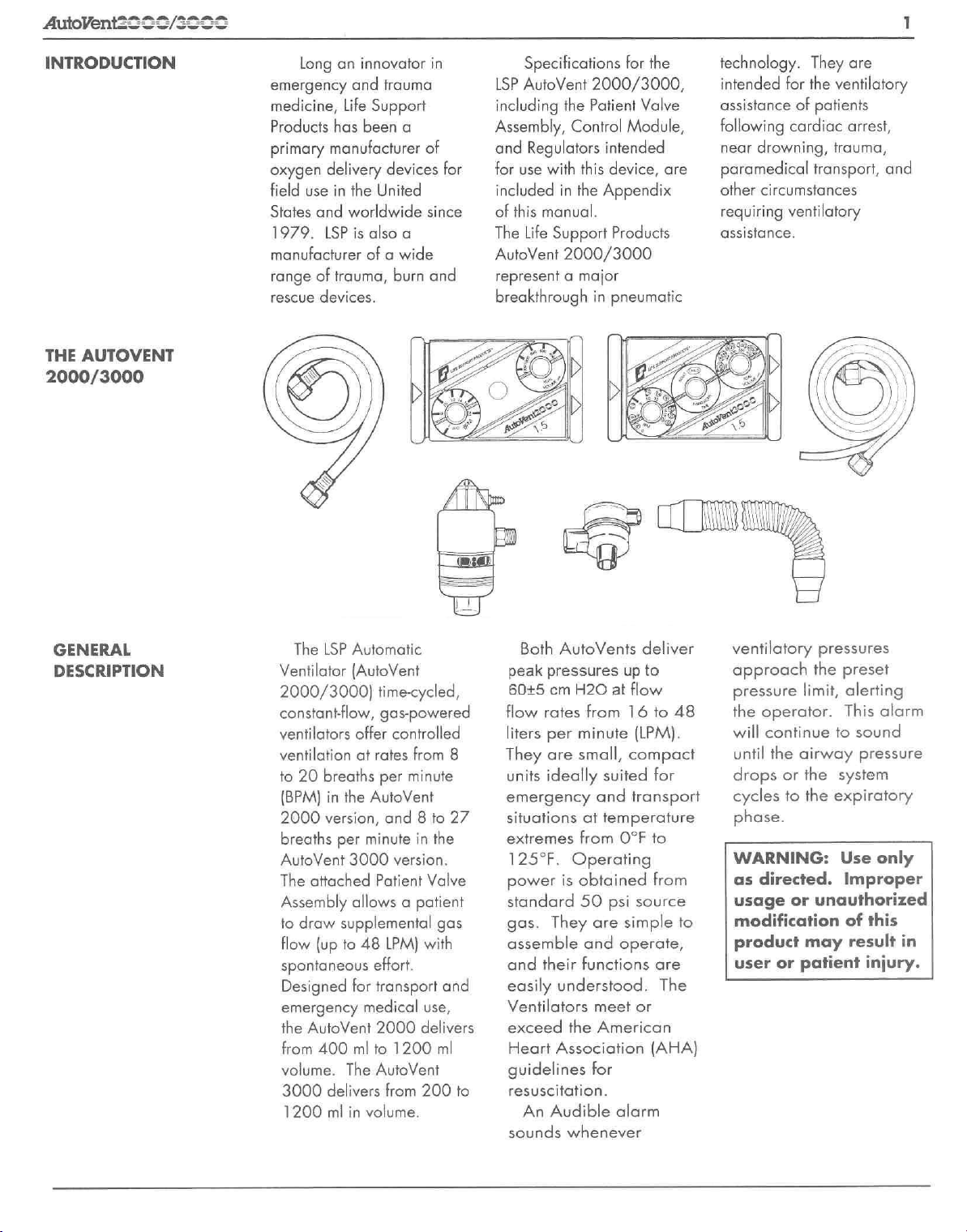
The
LSP
Automatic
Ventilator
2000/3000)
constantflow,
ventilators
ventilation
to
20
(BPM)
2000
breaths
AutoVent
The
Assembly
to
draw
flow
spontaneous
Designed
emergency
the
from
volume.
3000
1200
(AutoVent
time-cycled,
gas-powered
offer
at
rates
breaths
in
version,
attached
the
per
3000
per
AutoVent
and 8 to
minute
Patient
allows a patient
supplemental
(up
to
48
LPM)
effort.
for
transport
medical
AutoVent
400
delivers
ml
2000
ml
to
The
AutoVent
in
volume.
from
controlled
from
8
minute
27
in
the
version.
Valve
gas
with
and
use,
delivers
1200
ml
200
to
peak
60+5
flow
liters
They
units
Both
pressures
em
rates
per
are
ideally
AutoVents
H20
from
minute
small,
emergency
situations
extremes
125°F.
power
standard
gas.
assemble
and
easily
Ventilators
exceed
Heart
guidelines
resuscitation.
An
sounds
at
from
Operating
is
obtained
50
They
are
and
their
functions
understood.
meet
the
Association
for
Audible
whenever
deliver
up
to
at
flow
16
to
(LPM).
compact
suited
and
temperature
for
transport
O°F
to
from
psi
source
simple
operate,
are
The
or
American
(AHA)
alarm
48
to
ventilatory
approach
pressure
the
operator.
will
continue
until
drops
cycles
phase.
WARNING:
as
directed.
usage
modification
product
user
the
limit,
the
airway
or
the
to
the
or
unauthorized
may
or
patient
pressures
preset
alerting
This
alarm
to
sound
pressure
system
expiratory
Use
only
Improper
of
this
result
injury.
in
AutoVent2SSS/200€
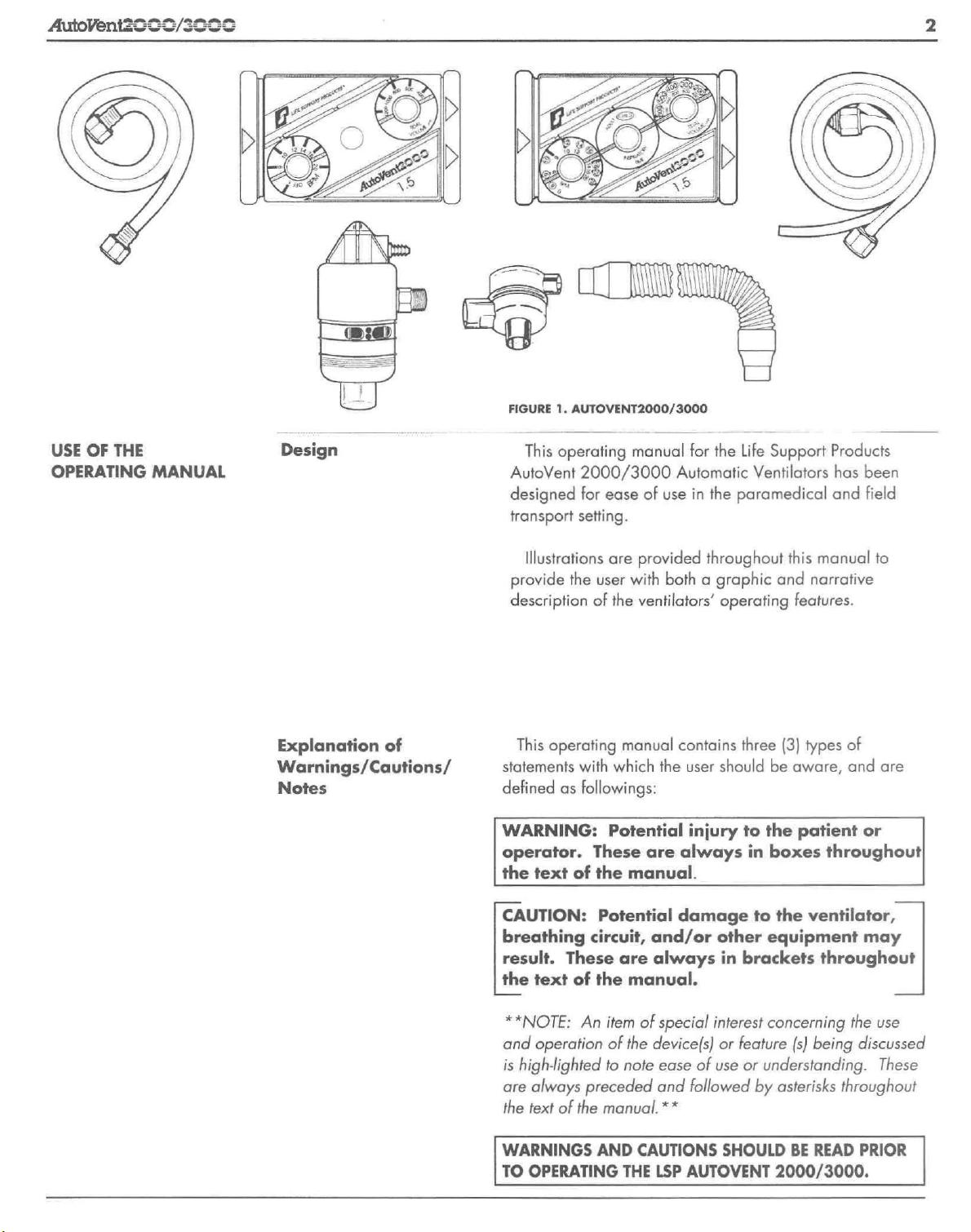
FIGURE
1.
AUTOVENT2000/3000
USE
OF
THE
OPERATING
MANUAL
This
operating
AutoVent
designed
transport
2000/3000
for
setting.
manual
ease
Automatic
of
use
for
in
the
the
Life
Support
Ventilators
paramedical
Products
has
and
been
field
Illustrations
provide
description
This
Explanation
Warnings/Cautions/
Notes
of
operating
statements
defined
WARNING:
operator.
the
CAUTION:
breathing
result.
the
**NOTE:
and
is
are
the
WARNINGS
TO
as
text
text
operation
high-lighted
always
text
of
OPERATING
are
provided
the
user with
of
the
ventilators’
manual
with
which
followings:
Potential
These
of
the
manual.
Potential
circuit,
These
are
of
the
An
item
of
the
to
note
preceded
the
manual.
AND
THE
manual.
of
CAUTIONS
throughout
both a graphic
operating
contains
the
user
should
injury
are
always
damage
and/or
always
special
device(s)
ease
and
**
LSP
other
in
interest
or
of
use
followed
SHOULD
AUTOVENT
this
manual
and
narrative
features.
three
(3)
types
be
aware,
to
the
patient
in
boxes
to
the
equipment
brackets
concerning
feature
or
understanding.
by
asterisks
2000/3000.
throughout!
ventilator,
throughout
(s)
being
BE
READ
to
of
and
are
or
may
the
use
discussed
These
throughout
PRIOR
AutoVentZSS5/SSSS
PERFORMANCE
CHARACTERISTICS
AND
FEATURES
The
AutoVent
flow,
gas
powered
ventilators’
to
20
version,
Should
obtained
patient
automatic
breaths
per
and 8 to
the
patient
on
demand
valve.
2000/3000
ventilators.
rate
to
minute
27
(BPM),
BPM
in
require
additional
by
making
are
time
This
be
set
in
the
AutoVent
an
cycled,
feature
by
the
the
AutoVent
breaths,
inspiratory
constant
allows
operator
3000
these
effort
the
from
8
2000
version.
can
be
on
the
PATIENT
ASSEMBLY
VALVE
The
patient
both
controlled
spontaneous
patient.
demand
indicator,
alarm,
valve.
15mm.
diameter/22mm.
diameter
valve
breaths
It
consists
valve, a visual
pressure
and
exhalation
It
has a standard
inside
adapter,
delivers
and
of
limit
outside
which
WI
to
a
the
is
<
compatible
other
airway
The
patient
spontaneous
upon
demand
makes
an
inspiratory
of
-2
cm.
HO.
control
the
for
____—
may
"O"
position
this
purpose.)
VISUAL
INDICATOR
with
masks
devices.
valve
allows
breathing
if
the
patient
(The
be
turned
if
desired
NI
X
and
effort
BPM
to
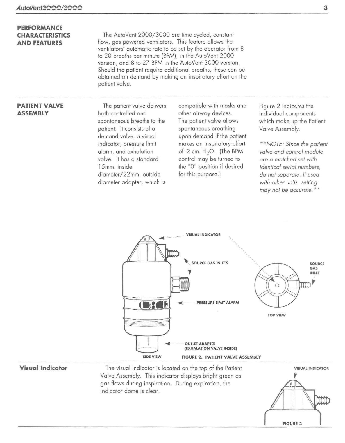
Figure 2 indicates
individual
which
Valve
**NOTE:
valve
are a matched
identical
do
with
may
components
make
Assembly.
Since
and
control
serial
not
separate.
other
units,
not
be
the
up
the
the
module
set
with
numbers,
If
used
setting
accurate.
Patient
patient
**
SOURCE
GAS
INLET
Visual
Indicator
The
visual
Valve
Assembly.
gas
flows
during
indicator
dome
SIDE
VIEW
indicator
is
This
indicator
inspiration.
is
clear.
FIGURE
located
on
displays
During
PRESSURE
OUTLET
ADAPTER
(EXHALATION
2.
PATIENT
the
top
bright
expiration,
VALVE
of
LIMIT
ALARM
INSIDE)
VALVE
the
Patient
green
the
ASSEMBLY
as
hy
TOP
VIEW
VISUAL
INDICATOR
y
il
/
[
FIGURE
п
3
AutoVent5222/5522
Pressure
Module
Limit
Alarm
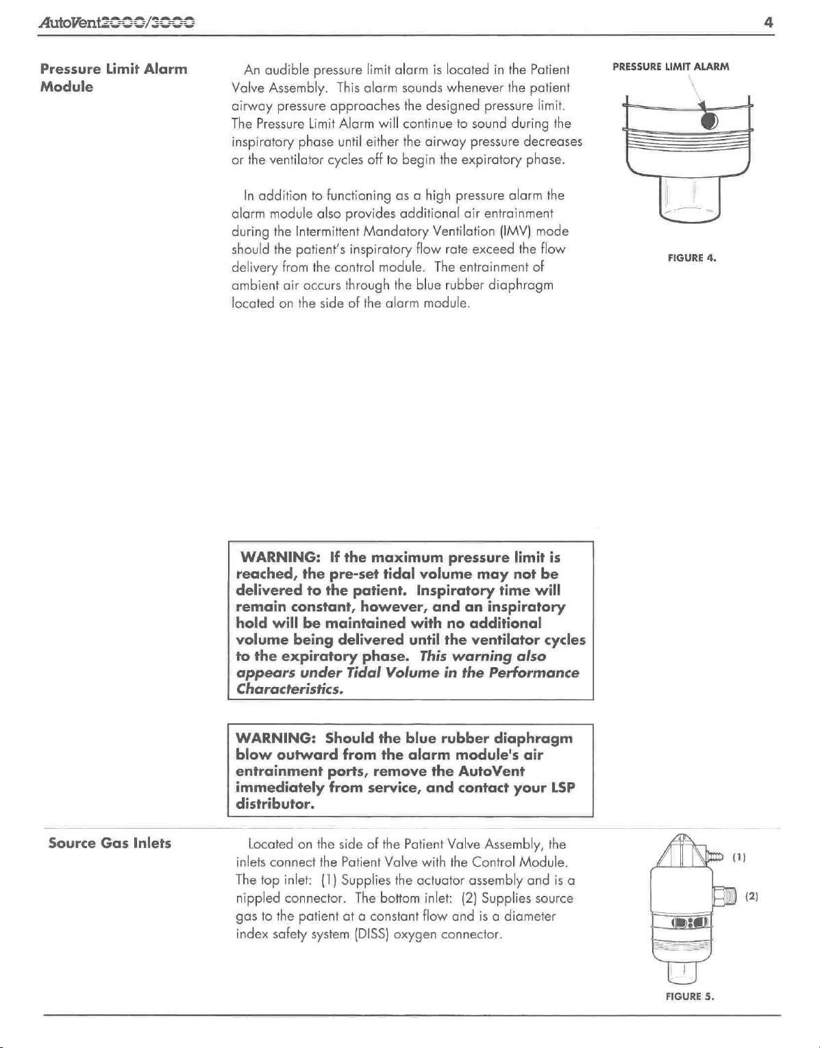
An
audible
Valve
Assembly.
airway
The
inspiratory
or
alarm
during
should
delivery
ambient
located
pressure
Pressure
the
ventilator
In
addition
module
the
the
from
air
on
phase
Intermittent
patient's
occurs
the
pressure
This
limit
alarm
approaches
Limit
Alarm
until
either
cycles
off
to
functioning
also
provides
Mandatory
inspiratory
the
control
through
side
of
the
alarm
sounds
the
designed
will
continue
the
airway
to
begin
as a high
additional
flow
module.
the
blue
alarm
module.
is
located
whenever
in
the
the
pressure
to
sound
during
pressure
the
expiratory
pressure
air
Ventilation
rate
The
entrainment
rubber
alarm
entrainment
(IMV)
exceed
diaphragm
Patient
patient
limit.
the
decreases
phase.
the
mode
the
flow
of
PRESSURE
LIMIT
FIGURE
ALARM
4.
Source
Gas
Inlets
WARNING:
reached,
delivered
remain
hold
will
volume
to
the
expiratory
appears
Characteristics.
WARNING:
blow
outward
entrainment
immediately
distributor.
Located
inlets
connect
The
top
inlet:
nippled
gas
index
connector.
to
the
safety
If
the
pre-set
to
the
constant,
be
maintained
being
under
Should
ports,
from
on
the
the
(1)
patient
system
the
maximum
tidal
patient.
however,
with
delivered
phase.
Tidal
from
service,
side
of
Patient
Supplies
The
at a constant
(DISS)
until
Volume
the
blue
the
alarm
remove
the
Patient
Valve
the
bottom
oxygen
pressure
volume
Inspiratory
and
This
the
and
with
actuator
inlet:
flow
may
an
inspiratory
no
additional
the
ventilator
warning
in
the
Performance
rubber
Valve
the
and
connector.
diaphragm
module's
AutoVent
contact
Assembly,
Control
assembly
(2)
Supplies
is a diameter
limit
not
time
also
air
your
Module.
is
be
will
cycles
LSP
the
and
is
source
a
FIGURE
5.
AutoVent20
Exhalation
Valve
99/3000
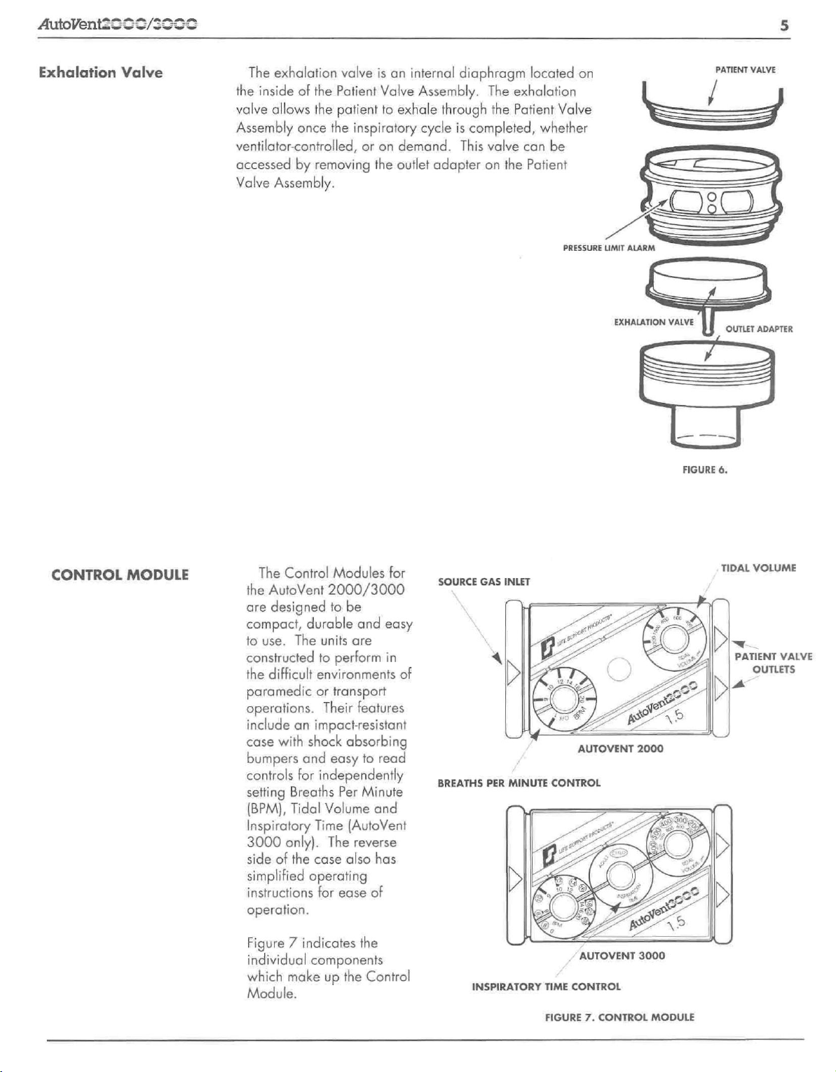
The
exhalation
the
inside
of
valve
allows
Assembly
ventilator-controlled,
accessed
Valve
once
by
Assembly.
valve
the
Patient
the
patient
the
inspiratory
or
removing
is
Valve
to
on
the
an
internal
diaphragm
Assembly.
exhale through
cycle
is
completed,
demand.
outlet
This
adapter
The
exhalation
the
Patient
valve
can
on
the
Patient
located
on
Valve
whether
be
PATIENT
/
VALVE
CONTROL
MODULE
The
Control
the
AutoVent
are
designed
compact,
to
use.
constructed
the
difficult
paramedic
operations.
include
case
with
bumpers
controls
setting
(BPM),
Inspiratory
3000
side
simplified
instructions
operation.
Breaths
Tidal
only).
of
Modules
2000/3000
to
durable
The
units
to
perform
environments
or
transport
Their
an
impactresistant
shock
and
easy
for
independently
Volume
Time
The reverse
the
case
operating
for
for
be
and
easy
are
in
of
features
absorbing
to
read
Per
Minute
and
(AutoVent
also
has
ease
of
SOURCE
BREATHS
GAS
PER
INLET
MINUTE
PRESSURE
AUTOVENT
CONTROL
A
LIMIT
ALARM
EXHALATION
2000
VALVE
—
——
FIGURE
OUTLET
6.
TIDAL
>
PATIENT
M
ADAPTER
VOLUME
VALVE
OUTLETS
Figure 7 indicates
individual
which
components
make
Module.
up
the
the
Control
INSPIRATORY
TIME
FIGURE
AUTOVENT
CONTROL
7.
CONTROL
3000
MODULE
AutoVent2522/552S
Source
Patient
Gas
Valve
Inlet
Outlets
located
marked
diameter
When a high
gas
delivered
the
An
this
a
specified
**NOTE:
prior
desired
located
and
the
top
Assembly
system
Supplies
inch
on
with
index
from a cylinder
to
the
Patient
Valve
Air/Oxygen
system,
between
oxygen
Use
to
patient
oxygen
on
marked
Control
outlet
Module
(1)
at a constant
(DISS)
the
threaded
the
left
side
an
arrow,
safety
pressure
Control
the
system
line
or
bulk
Module
Assembly.
Blender
the
source
concentration.
of
an
Oxygen
use
in
order
concentration
the
right
side
with
arrows,
with
the
Supplies
oxygen
Patient
female
source
flow
connector.
Valve
connecior.
of
the
Control
source
(DISS)
is
attached
oxygen
and
can
also
and
Analyzer
to
accurately
to
be
of
the
Control
the
patient
Patient
gas
and
is a diameter
Actuator
Module
gas
inlet
is a standard
male
oxygen
to a 50
source,
be
the
this
cycled
for
inserted
ventilator,
is
recommended
measure
delivered.
Module
valve
outlets
Valve
Assembly.
to
the
Patient
The
bottom
and
is a unique
and
connector.
psi
source
gas
is
delivery
in
line
with
to
deliver
the
**
body
connect
The
Valve
index
safety
outlet:
(2)
7/16
to
SOURCE
GAS
INLET
FIGURE
FIGURE
8.
9.
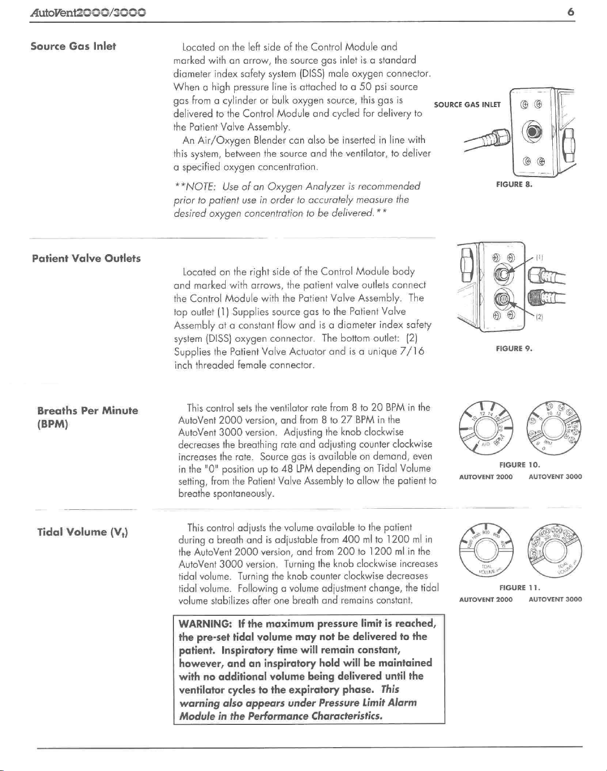
Breaths
(BPM)
Tidal
Volume
Per
Minute
(Vi)
This
control
AutoVent
AutoVent
decreases
increases
in
setting,
breathe
This
2000
3000
the
the
rate.
the
"O"
position
from
the
spontaneously.
control
during a breath
the
AutoVent
AutoVent
tidal
volume.
tidal
volume.
volume
2000
3000
stabilizes
WARNING:
the
pre-set
patient.
however,
with
ventilator
warning
Module
tidal
Inspiratory
and
no
additional
cycles
also
in
the
sets
the
ventilator
version,
and
version.
breathing
Source
up
to
Patient
adjusts
and
version.
Turning
Valve
the
is
adjustable
version,
the
rate
from 8 to
Adjusting
rate
and
adjusting
gas
is
available
48
LPM
depending
Assembly
volume
Turning
and
knob
counter
available
from
the
Following a volume
after
one
breath
If
the
maximum
volume
time
an
inspiratory
volume
to
the
appears
Performance
pressure
may
will
being
expiratory
under
Pressure
Characteristics.
from 8 to
the
27
BPM
knob
clockwise
20
counter
on
demand,
on
to
allow
to
the
from
400
ml
to
200
to
1200
knob clockwise
clockwise
adjustment
and
change,
remains
limit
not be
remain
hold
delivered
constant,
will
be
delivered
phase.
Limit
BPM
in
the
in
the
clockwise
even
Tidal
Volume
the
patient
patient
1200
ml
in
ml
in
the
increases
decreases
the
tidal
constant.
is
reached,
to
the
maintained
until
the
This
Alarm
to
AUTOVENT
AUTOVENT
FIGURE
2000
FIGURE
2000
10.
AUTOVENT
11.
AUTOVENT
3000
3000
AutoVent2552/5555
Tidal
Volume
(Continued)
Inspiratory
Time
(Vi)
(Ti)
**NOTE:
the
AutoVent
with
pressure alarm
This
allows
settings
respectively.
setting
corresponds
Volume
setting
corresponds
control
of
approximately
CAUTION:
center
either
WARNING:
3000
Tidal
It
is
2000/3000
the
patient
control
knob
adjustment
allow
selection
The
is
approximately
fo
control
is
approximately
to
knobs.
control
of
the
be
adjusted
Volume
recommended
circuit
near
limit.**
in
the
center position
of
the
patient's
of
Adult
inspiratory
.75
seconds
the
circled
orange
knobs.
the
The
When
The
1.5
white
settings
AutoVent
1.5
seconds.
you
knob
end
stops.
Should
settings.
the
after
inspiratory
seconds
to
that
you
during
time
2000
select
maintenance
the
outlet
of
inspiratory
and
Child
for
the
circled
and
settings
time
and
on
the
BPM
has a pre-set
either
the
appropriate
inspiratory
initial
setup,
periodically
by
placing a pressure
to
verify
inspiratory
the
AutoVent
time.
The
two
inspiratory
when
on
the
for
when
and
time
orange
selected
the
selected
Adult
time
child
BPM
and
white
Tidal
Volume
inspiratory
or
setting
control
it
will
check
3000
Tidal
Adult
time
Child
and
alter
the
performance
pressures
setting,
knob
the
and
position
on
patient's
characteristics
manometer
the
accuracy
C
^
FIGURE
11A.
rotate
the
the
it
against
AutoVent
BPM
and
in
li
line
of
the
of
Patient
Tubing
Line
Non-Rebreathing
Valve
Hose
Valve
and
and
Corrugated
Supply
Oxygen
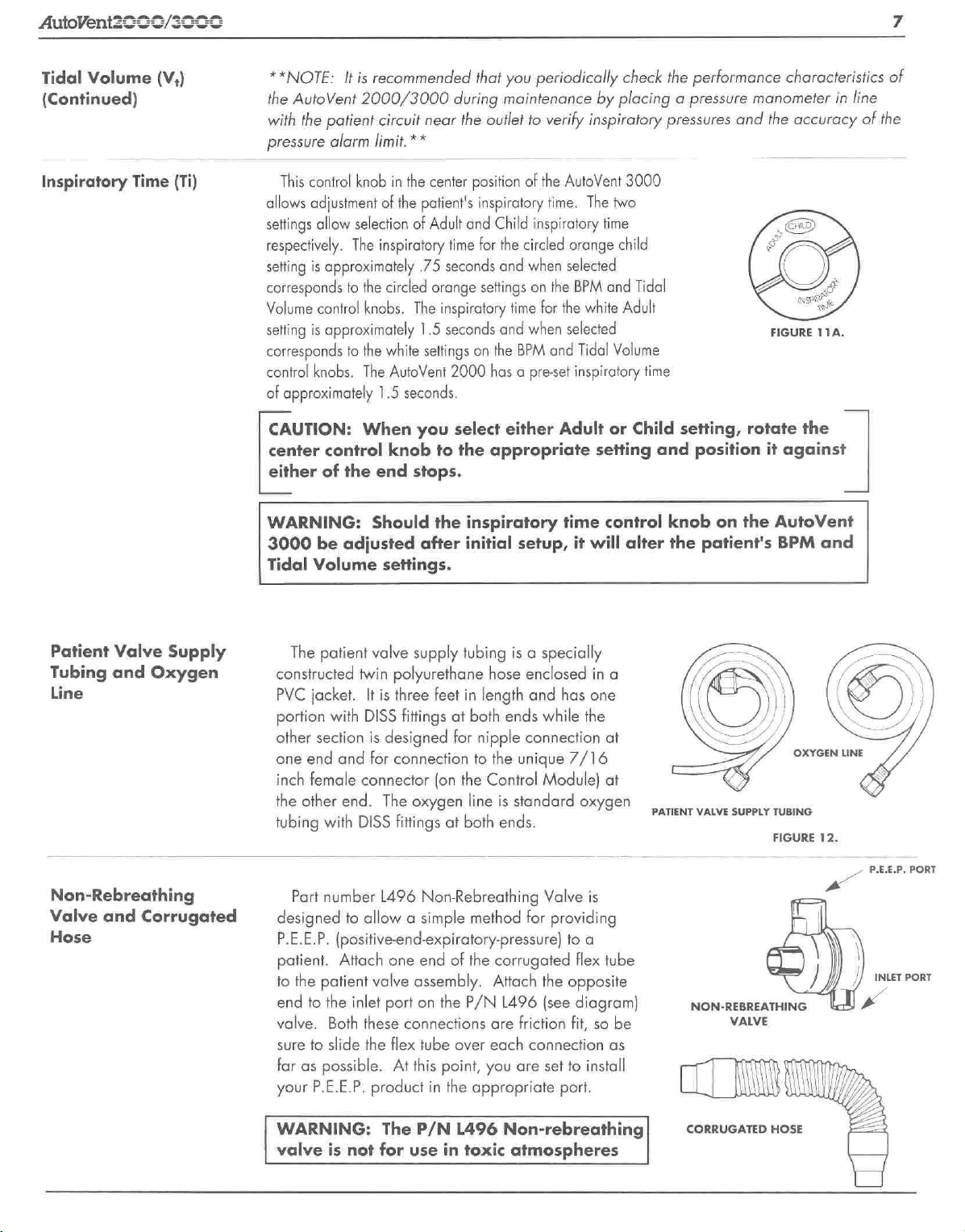
The
patient
constructed
PVC
jacket.
portion
other
one
inch
the
tubing
designed
P.E.E.P.
patient.
to
end
valve.
sure
far
your
WARNING:
valve
with
section
end
and
female
other
end.
with
Part
number
(positive-end-expiratory-pressure]
Attach
the
patient
to
the
Both
to
slide
as
possible.
P.E.E.P.
is
valve
supply
twin
polyurethane
It
is
three
DISS
fittings
is
designed
for
connection
connector
The
oxygen
DISS
fittings
L496
Non-Rebreathing
to
allow a simple
one end
valve
assembly.
inlet
port
on
these
connections
the
flex
tube
At
this
product
not
for
The
in
P/N
use
tubing
hose
feet
in
length
at
both
for
nipple
to
(on the
Control
line
at
both
method
of
the
the
P/N
are
over
each
point,
you
the
appropriate
L496
in
toxic
is a specially
enclosed
and
ends
while
connection
the
unique
Module)
is
standard
ends.
Valve
for
corrugated
Attach
the
L496
(see
friction
connection
are
set
Non-rebreathing
atmospheres
in
a
has
one
the
at
7/16
at
oxygen
is
providing
to
a
flex
tube
opposite
diagram)
fit,
so
as
to
install
port.
be
PATIENT
VALVE
SUPPLY
NON-REBREATHING
VALVE
CORRUGATED
TUBING
FIGURE
12.
P.E.E.P.
PORT
As
HOSE
 Loading...