

Allied 4SCU16LS PRODUCT SPECIFICATIONS
4SCU16LS
PRODUCT SPECIFICATIONS
16 SEER SPLIT SYSTEM
TWO-STAGE AIR CONDITIONER
FORM NO. 4SCU16LS-100 (01/2021)
COMPONENTS
• Communicating capable control board works with Comfort Sync®
thermostat (or conventional thermostat)
• Self diagnostics control board for quick trouble shooting; saves
up to 10 fault codes regardless of power interrupt
• Factory installed high and low pressure switches
• Thread-on type pressure switches with valve core for quick
service
• Service valves mounted for easy brazing and service
• Factory installed crankcase heater
• Factory installed TXV for excellent refrigeration control
• Fan orifice for sound reduction and efficient performance
• Charged for 15 feet of line set
• Can be matched with Comfort Sync® enabled or conventional
indoor unit
COMMUNICATING THERMOSTAT ENABLED
COMPRESSOR
• High-efficiency 2 stage Copeland UltraTech™ scroll compressor
• R410a refrigerant
• Heavy-duty compressor sound blanket for quiet operation
• Internally protected against high temperature motor overload
conditions
CABINET
• Four metal louvered panels easily removable for coil cleaning and
service
• Corner-mounted controls for easy service
• Rounded corner posts for safety and attractive appearance
• Baked polyester paint finished over galvanized steel for maximum
durability
• Removable PVC coated wire fan discharge grill
• External gauge ports for easy service
WARRANTY
10 year limited warranty on compressor
10 year limited warranty on all parts, extended warranty available*
*Warra nty provides for a total of 10 years of limited warrant y coverage (Standard
5-yea r limited p arts warranty plus an add itional 5 -year limited ex tended p arts
warrant y). Warrant y must be registered online within 60 day s of installation to
qualif y for 10 -year coverage. Unregistere d equipment defaults to 5-year cove rage.
See full warranty at www.allied air.com for terms, conditio ns and exclusions .
COILS
• Enhanced tube-and-fin coil design featuring MHT™ Technology
• Raised coil prevents debris from impeding airflow
DESIGN
• Designed to perform in temperatures up to 125 degrees F
* Check that equipment complies with all applicable building codes, laws, and regulations for its intended use prior to installation.
Page 1
ENHANCED SPLIT SYSTEM 4SCU16LS
MODEL NUMBER GUIDE
4 SCU 16 LS 1 36 P - 3 A4 SCU 16 LS 1 36 P - 3 A
REFRIGERANT
4 = R410A
SCU
SPLIT CONDENSING UNIT
16
16 SEER NOMINAL
LS
LOUVERED TWO-STAGE
COMMUNICATING ENABLED
MINOR REVISION CODE
MAJOR REVISION CODE
1-PHASE, 60 HZ
NOMINAL CAPACITY
36 - 36,000 BTUH
REGION RESTRICTIONS
STANDARD MODEL
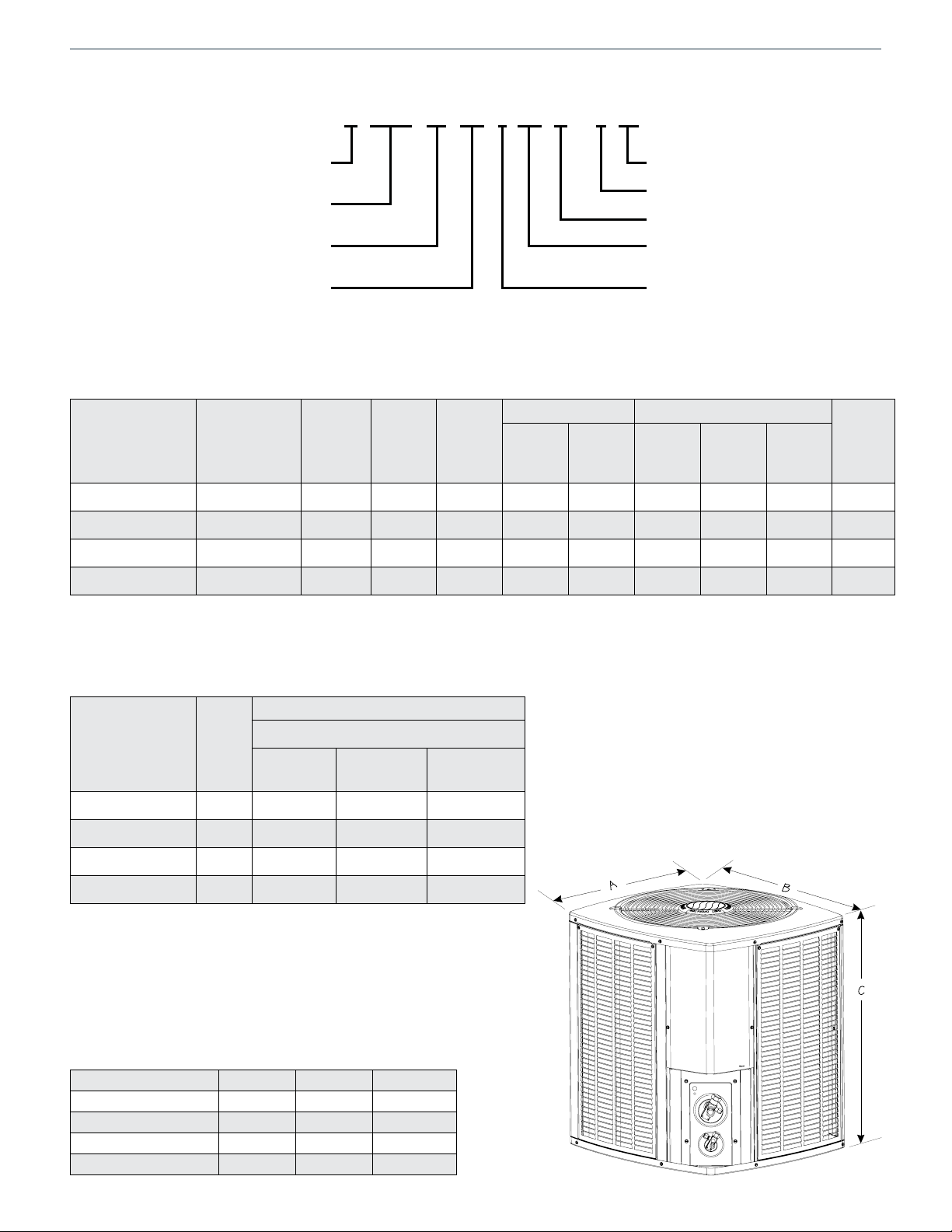
PHYSICAL AND ELECTRICAL
Max.
Model
Voltage/Hz/
Phase
Voltage
Range
Min.
Circuit
Amp.
Over
Current
Device
(amps)
4SCU16LS124P-3 208-230/60/1 197-253 15.7 25 11.7 58 1.0 1/6 825 212
4SCU16LS136P-3 208-230/60/1 197-253 20.2 35 15.3 83 1.1 1/6 825 245
4SCU16LS148P-3 208-230/60/1 197-253 28.2 45 21.2 104 1.1 1/6 825 287
4SCU16LS160P-3 208-230/60/1 197-253 35.6 60 27.1 153 1.7 1/4 825 332
Note: Weig hts listed are unit weights with pa ckaging
Compressor Fan Motor
Rated
Load
(amps)
Locked
Rotor
(amps)
Rated
Load
(amps)
Rated HPNom.
RPM
Weight
(lbs.)
UNIT SOUND RATINGS
Estimated Sound Pressure (dBA)
Model
Sound
Power
1
One Meter
(3.3 feet)
Approximate Distance
Two Meters
(6.6 feet)
3
Three Meters
(9.8 feet)
4SCU16LS124P-3 74 66 60 56
4SCU16LS136P-3 74 66 60 56
4SCU16LS148P-3 76 68 62 58
4SCU16LS160P-3 76 68 62 58
1 Rated in accordance with AHRI standard 270 (2015)
2 Rated in accordance with AHRI standard 275 (2010)
3 Based only on distance factor; other factors may change this value such as:
• Unit location (reflective surfaces adjacent to the unit)
• Barrier shielding sources
• Sound path/elevation
• Outside noise sources
DIMENSIONS (IN.)
Model No. A - Width B - Depth C - Height
4SCU16LS124P-3 29.25 31.25 43.75
4SCU16LS136P-3 29.25 31.25 29.75
4SCU16LS148P-3 29.25 31.25 37. 75
4SCU16LS160P-3 35.75 37.75 43.75
2
Page 2
ENHANCED SPLIT SYSTEM 4SCU16LS
REFRIGERATION DATA
Model
System
Charge
(oz.) *
Indoor TXV
Refrigerant Line Size Outdoor Unit Connection Indoor Unit Connection
Suction Liquid Suction Liquid Suction Liquid
4SCU16LS124P-3 117 A4TXV01/H4TXV01 3/4
4SCU16LS136P-3 137 A4TXV01/H4TXV02 7/8 7/ 8
3/8
4SCU16LS148P-3 180 A4TXV02/H4TXV02 7/ 8 7/8
4SCU16LS160P-3 214 A4TXV02/H4TXV03 1 1/8 7/ 8
* Factory charged for 15 fe et of line set ; adjust 0 .6 oz per foot (see installation instructi ons).
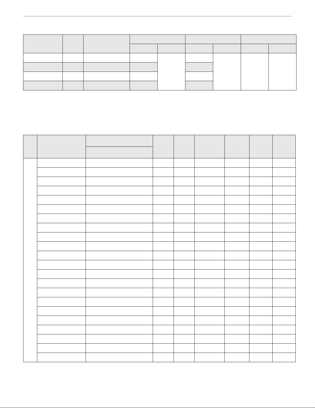
COOLING PERFORMANCE WITH AIR HANDLERS & FURNACES
Indoor Model
SEER EER
Evap. Coil or Air Handler
3
BCE4M24S* 15.10 12.20 24000 17,800 850 650
BCE4M30S* 15.10 12.20 24000 17,800 850 650
Model
Outdoor
Variable Speed
Furnace
BCS2M36V00NA1P+A4TXV01 15.10 12.20 24000 17,800 800 600
3/4
AHRI Rate
Capacity1
BTUH
3/8
Sensible
Rated
Capacity
VARIES
BASED
ON COIL
MATCH
CFM
High
3/8
CFM
Low
EFV08BC E*1P36B+A4TXV01+TDR 15.10 12.20 24000 17,800 850 650
A80US2V070A12 E*1P19A+A4TXV01+TDR 16.00 13.00 24000 17,800 820 650
A80US2V070A12 E*1P23A+A4TXV01+TDR 16.00 13.00 24000 17,800 820 650
A80US2V070A12 E*1P29A+A4TXV01+TDR 16.00 13.00 24000 17,800 780 495
A80US2V070A12 E*1P36A+A4TXV01+TDR 16.00 13.00 24000 17,800 780 495
A80US2V090B12 E*1P23B+A4TXV01+TDR 15.10 13.00 24000 17,800 780 495
A80US2V090B12 E*1P29B+A4TXV01+TDR 16.00 13.00 24000 17,800 780 495
A80US2V090B12 E*1P30B+A4TXV01+TDR 16.00 13.00 24000 17,800 800 500
A80US2V090B12 E*1P36B+A4TXV01+TDR 15.10 12.50 24000 17,800 780 495
A80DS2V070A12 E*1P36A+A4TXV01+TDR 14.50 12.20 22000 16,300 800 575
4SCU16LS124P-3
A96US2V045B12 E*1P23B+A4TXV01+TDR 16.00 13.00 24000 17,800 815 540
A96US2V045B12 E*1P29B+A4TXV01+TDR 16.00 13.00 24000 17,800 815 540
A96US2V045B12 E*1P30B+A4TXV01+TDR 16.00 13.00 24000 17,800 815 540
A96US2V045B12 E*1P36B+A4TXV01+TDR 16.00 13.00 24000 17,800 815 540
A96US2V070B12 E*1P23B+A4TXV01+TDR 16.00 13.00 24000 17,800 800 600
A96US2V070B12 E*1P29B+A4TXV01+TDR 16.00 13.00 24000 17,800 800 600
A96US2V070B12 E*1P30B+A4TXV01+TDR 16.00 13.00 24000 17,800 800 600
A96US2V070B12 E*1P36B+A4TXV01+TDR 16.00 13.00 24000 17,800 800 600
A96US2V090C12 E*1P30C+A4TXV01+TDR 16.00 13.00 24000 17,800 800 600
Note:
1 Certified in ac cordan ce with Unitary Air Conditioner Ce rtific ation Pro gram, which is based on AH RI Stan dard 21 0/240
2 Required to achieve AHR I rating. If NA (Not Applic able) is in the piston column, the n TX V is required
3 A blower tim e delay relay is required to achieve AHRI rating. This featu re is stand ard on all Allied Air Enterprises Furna ce and AH p roducts
Page 3
 Loading...