

Alliance Laundry Systems SCA020VC, SCL060VL, SCT020VY, SCL030VE, SCU080VY Original Instruction
...Page 1
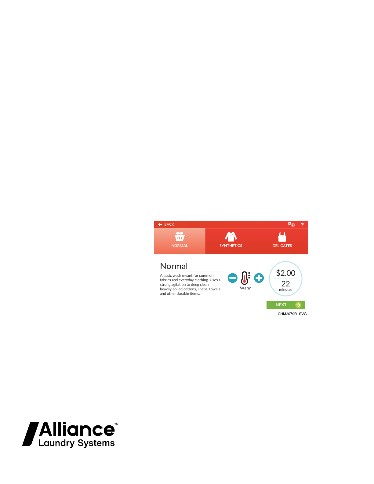
Washer-Extractor
Cabinet Hardmount
Quantum Touch Vend Control
Refer to Page 13 for Model Identification
Programming
Original Instructions
Keep These Instructions for Future Reference.
CAUTION: Read the instructions before using the machine.
(If this machine changes ownership, this manual must accompany machine.)
www.alliancelaundry.com
Part No. F8669401ENR4
September 2019
Page 2

Page 3
WARNING
Machine installations must comply with minimum
specifications and requirements stated in the applicable Installation Manual, any applicable municipal
building codes, water supply requirements, electrical
wiring regulations and any other relevant statutory
regulations. Due to varied requirements and applicable local codes, this machine must be installed, adjusted, and serviced by qualified maintenance personnel familiar with applicable local codes and the
construction and operation of this type of machinery.
They must also be familiar with the potential hazards
involved. Failure to observe this warning may result
in personal injury, property damage, and/or equipment damage, and will void the warranty.
W820
NOTE: The WARNINGS and IMPORTANT SAFETY INSTRUCTIONS appearing in this manual are not meant
to cover all possible conditions and situations that may
occur. Common sense, caution, and care must be exercised when installing, maintaining, or operating the
machine.
Any problems or conditions not understood should be reported to
the dealer, distributor, service agent or the manufacturer.
Regulatory Statements
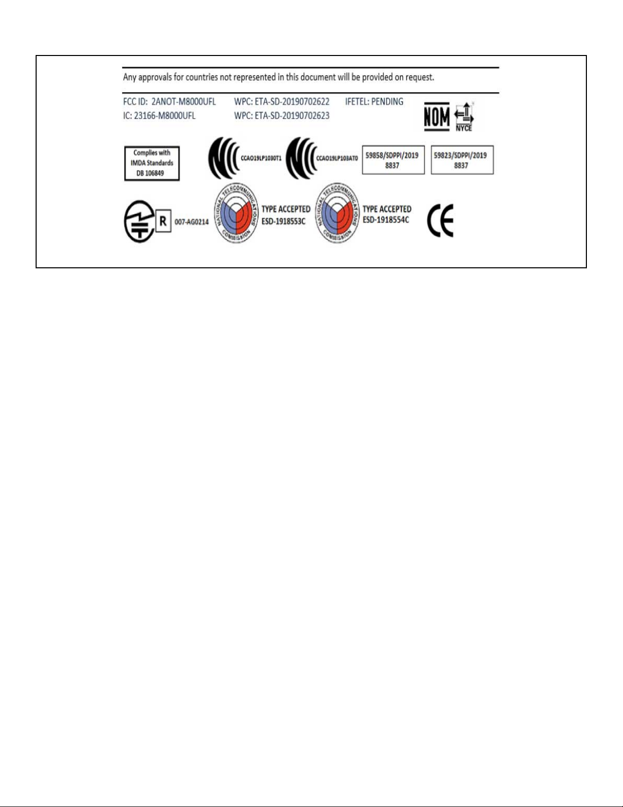
PRODUCT COMPLIANCE
Users of this product are cautioned not to make modifications or
changes that are not approved by Alliance Laundry Systems,
LLC. Doing so may void the compliance of this product with applicable laws and regulatory requirements and may result in the
loss of the user’s authority to operate the equipment.
UNITED STATES
This device complies with Part 15 of the FCC Rules. Operation is
subject to the following two conditions; (1) This device may not
cause harmful interference, and (2) this device must accept any
interference received, including interference that may cause undesired operation.
This equipment has been tested and found to comply with the
limits for a Class B digital device, pursuant to Part 15 of the FCC
Rules. These limits are designed to provide reasonable protection
against harmful interference in a residential installation. This
equipment generates uses and can radiate radio frequency energy
and, if not installed and used in accordance with the instructions,
may cause harmful interference to radio communications. However, there is no guarantee that interference will not occur in a
particular installation. If this equipment does cause harmful inter-
ference to radio or television reception, which can be determined
by turning the equipment off and on, the user is encouraged to try
to correct the interference by one or more of the following measures:
• Reorient or relocate the radio or television receiving antenna.
• Increase the separation between the computer equipment or
receiver.
• Connect the equipment into an outlet on a circuit different
from that to which the radio or television receiver is connected.
• Consult the dealer or experienced radio television technician
for help.
CAUTION
To comply with the limits of the Class B device, pursuant to Part 15 of the FCC Rules, this device is to
comply with Class B limits. All peripherals must be
shielded and grounded. Operation with non-certified
peripherals or non-shielded cables is likely to result
in interference and reception of the device.
W1004
Radiation Exposure Statement: This equipment complies with
FCC radiation exposure limits set forth for an uncontrolled environment. The radio installed in this equipment and is intended to
operate with minimum distance 20cm between the radiator and
your body.
Limited Channels Fixed For Use In USA: IEEE 802.11b or
802.11g or 802.11n(HT20) operation of this product in the U.S. is
firmware-limited to Channel 1 through 11.
CANADA - CAN ICES-3(B)/NMB-3(B)
This device contains license-exempt transmitter(s)/receiver(s)
that comply with Innovation, Science and Economic Development Canada’s license-exempt RSS(s) standards. Operation is
subject to the following two conditions:
• This device may not cause interference.
• This device must accept any interference, including interference that may cause undesired operation of the device.
Radiation Exposure Statement: This equipment complies with
Innovation, Science and Economic Development Canada’s radiation exposure limits set forth for in RSS-102. The radio installed
in this equipment is installed and is intended to operate with minimum distance 20cm between the radiator and your body.
EUROPE
Products bearing the CE mark comply with the following EU directives:
©
Copyright, Alliance Laundry Systems LLC -
DO NOT COPY or TRANSMIT
3 Part No. F8669401ENR4
Page 4

• EMC Directive 2014/30/EU
• Low Voltage Directive 2014/35/EU
• Ecodesign Directive 2009/125/EC
• RoHS Directive 2011/65/EU
If the product has telecommunications functionality, it also complies with the requirements of the following EU directive:
• Radio Equipment Directive 2014/53/EU
Compliance with these Directives implies conformity to harmonized European standards that are noted in the EU Declaration of
Conformity which is available upon request.
Alliance Laundry Systems products comply with the requirement
of Article 10(2) as it can be operated in at least one Member State
as examined and the product is compliant with Article 10(10) as
it has no restrictions on putting into service in all EU member
states.
This device contains a 2.4GHz transceiver, intended for indoor
use only in all EU member states, EFTA states, and Switzerland.
Attention has been given to allowed operational frequencies. For
detailed information concerning installations in France, the user
should contact the national spectrum authority in France (http://
www.arcep.fr/ )
Be aware that outdoor installations require special attention and
will only be handled by trained and qualified installation personnel. No one from the general-public is permitted to install wireless products outdoors when external antennas, power and
grounding must be installed for use.
AUSTRALIA/NEW ZEALAND
The radio in this equipment complies with and is certified to the
Australian and New Zealand regulatory requirements.
BRAZIL ANATEL
This equipment operates in secondary status, that is, it is not entitled to protection against harmful interference, even for type stations, and cannout cause interference to systems operating in primary status.
CHINA SRRC
This product is equipped with a certified wireless device pursuant
to Article 2-1-19 of the Certification Ordinance. No changes are
authorized to the radio or the antenna of the approved device.
MEXICO IFETEL
“The operation of this equipment is subject to the following two
conditions: (1) it is possible that this equipment or device does
not cause harmful interference and (2) this equipment or device
must accept any interference, including that which may cause its
unwanted operation.”
SOUTH KOREA (KC)
The radio device has received certification of conformance in accordance with the Radio Waves Act. Integration of this radio into
a final product does not require additional radio certification provided installation instructions are followed. No changes are authorized to the radio or the antenna of the approved device.
TAIWAN
The information in this section applies to products bearing the
Taiwan National Communications Commission mark:
This telecom equipment has complied with NCC regulations.
According to “Administrative Regulations of Low Power Radio
Waves Radiated Devices:
Article 12 The low-power radio-frequency devices must not be
altered by changing the frequency, enhancing emission power,
adding external antenna, and modification of original design
characteristic as well as function.
Article 14 The operation of the low-power radio-frequency devices is subject to the conditions that no harmful interference is
caused. The user must stop operating the device immediately
should harmful interference is caused and shall not resume until
the condition causing the harmful interference has been corrected.
Moreover, the interference must be accepted that may be caused
by the operation of an authorized communications, or ISM equipment. (1) Precautions (marked in the product manual and on outer packaging)
The radio device has recieved certification of conformance in accordance with the People's Republic of China State Radio Regulation Committee (SRRC) certification scheme. Integrations of
this radio into a final product does not require additional radio
certification provided installation instructions are followed. No
changes are authorized to the radio or the antenna of the approved device.
JAPAN
©
Copyright, Alliance Laundry Systems LLC -
DO NOT COPY or TRANSMIT
THAILAND
The information in this section applies to products approved by
the Thailand National Communications Commission:
These telecommunication and device are compliance with the requirements of National Broadcasting and Telecommunication
Commission.
4 Part No. F8669401ENR4
Page 5
MIX4N_SVG
Figure 1
©
Copyright, Alliance Laundry Systems LLC -
DO NOT COPY or TRANSMIT
5 Part No. F8669401ENR4
Page 6

Table of Contents
Safety Information..................................................................................9
Explanation of Safety Messages....................................................................... 9
Important Safety Instructions........................................................................... 9
Safety Decals................................................................................................10
Operator Safety.............................................................................................10
Introduction..........................................................................................12
Model Identification......................................................................................12
Serial Plate Location..................................................................................... 17
Replacement Parts ........................................................................................18
Customer Service..........................................................................................18
Preliminary Information.......................................................................19
About the Control......................................................................................... 19
IR Communications...................................................................................... 19
IR Communications Menu..........................................................................19
Wi-Fi Communications..................................................................................19
Audit Information......................................................................................... 19
Special Features....................................................................................20
Break-In Alarm.............................................................................................20
Cycle Time Display.......................................................................................20
Cycle Completed Timer.................................................................................20
Passcode Security......................................................................................... 20
Language Selection.......................................................................................20
Lucky Cycle.................................................................................................20
Speed Cycle................................................................................................. 20
Special Vend.................................................................................................20
Increased Water Levels..................................................................................20
Increased Spin Speed.................................................................................... 20
Dispense Soap.............................................................................................. 20
Control Identification........................................................................... 21
Operational Touch Display.............................................................................21
Operation Modes.......................................................................................... 22
Ready Mode............................................................................................. 22
Lockout Mode...........................................................................................22
Drop Off Mode......................................................................................... 22
Auto-Flush Mode...................................................................................... 23
Overflow Mode.........................................................................................23
©
Copyright 2019, Alliance Laundry Systems LLC
All rights reserved. No part of the contents of this book may be reproduced or transmitted in any form or by any means without the expressed
written consent of the publisher.
©
Copyright, Alliance Laundry Systems LLC -
DO NOT COPY or TRANSMIT
6 Part No. F8669401ENR4
Page 7

Machine Error Mode..................................................................................23
Internal Control Failure..............................................................................23
Coast Down Mode.....................................................................................24
Shutdown Mode........................................................................................ 24
Out of Order Mode.................................................................................... 24
Menu Navigation.................................................................................. 26
Opening the Service Door..................................................................... 29
Stacked Washer-Extractor/Tumble Dryer.........................................................29
Machine Cycle Definition and Operation.............................................. 31
Machine Cycle Operation.............................................................................. 31
Approach Screen...........................................................................................31
Cycle Preset ................................................................................................ 32
Speed Cycle................................................................................................. 33
Pre-Clean (If Available).................................................................................33
Help Menu .................................................................................................. 34
Language Selection Panel ............................................................................. 34
Start a Cycle.................................................................................................34
Close Door Menu..........................................................................................35
Run Menu ................................................................................................... 35
Cycle Pause Menu ........................................................................................37
Cycle Complete Menu...................................................................................37
Lucky Cycle Mode........................................................................................37
Manual Programming...........................................................................38
System Menu................................................................................................38
Passcode Menu......................................................................................... 38
Save Changes Menu.................................................................................. 38
Rapid Advance Activation..........................................................................39
Cancel Cycle.............................................................................................39
Clear Active Error .................................................................................... 39
Clear Partial Vend .....................................................................................40
Change Vend Price ................................................................................... 40
Settings Menu.......................................................................................41
Vend Settings ...............................................................................................41
Basic Settings .............................................................................................. 53
Machine Settings ......................................................................................... 57
Cycle Settings...............................................................................................61
Audit Data Menu.................................................................................. 84
Diagnostics Menu..................................................................................85
Machine ID Menu.........................................................................................85
Alarms Menu................................................................................................85
©
Copyright, Alliance Laundry Systems LLC -
DO NOT COPY or TRANSMIT
7 Part No. F8669401ENR4
Page 8

Inputs/Outputs Menu.....................................................................................86
Factory Test Menu........................................................................................ 86
Individual Tests Menu................................................................................... 90
Machine Errors......................................................................................... 92
Service Schedule Menu......................................................................... 99
Reset Menu.........................................................................................100
Default Cycles.....................................................................................101
©
Copyright, Alliance Laundry Systems LLC -
DO NOT COPY or TRANSMIT
8 Part No. F8669401ENR4
Page 9
Safety Information
Safety Information
Explanation of Safety Messages
Precautionary statements (“DANGER,” “WARNING,” and
“CAUTION”), followed by specific instructions, are found in this
manual and on machine decals. These precautions are intended
for the personal safety of the operator, user, servicer, and those
maintaining the machine.
DANGER
Indicates an imminently hazardous situation that, if
not avoided, will cause severe personal injury or
death.
WARNING
Indicates a hazardous situation that, if not avoided,
could cause severe personal injury or death.
CAUTION
Indicates a hazardous situation that, if not avoided,
may cause minor or moderate personal injury or
property damage.
Additional precautionary statements (“IMPORTANT” and
“NOTE”) are followed by specific instructions.
IMPORTANT: The word “IMPORTANT” is used to inform the reader of specific procedures where minor
machine damage will occur if the procedure is not followed.
NOTE: The word “NOTE” is used to communicate installation, operation, maintenance or servicing information that is important but not hazard related.
Important Safety Instructions
WARNING
To reduce the risk of fire, electric shock, serious injury or death to persons when using your washer,
follow these basic precautions:
W023
• Read all instructions before using the washer.
• Install the washer according the INSTALLATION instructions. Refer to the EARTH/GROUND instructions in the IN-
STALLATION manual for the proper earth/ground connection
of the washer. All connections for water, drain, electrical
power and earth/ground must comply with local codes and be
made by licensed personnel when required. It is recommended that the machine be installed by qualified technicians.
• Do not install or store the washer where it will be exposed to
water and/or weather.
• To prevent fire and explosion, keep the area around machine
free from flammable and combustible products. Do not add
the following substances or textiles containing traces of the
following substances to the wash water: gasoline, kerosene,
waxes, cooking oils, vegetable oils, machine oils, dry-cleaning solvents, flammable chemicals, thinners, or other flammable or explosive substances. These substances give off vapors
that could ignite, explode or cause the fabric to catch fire by
itself.
• Under certain conditions, hydrogen gas may be produced in a
hot water system that has not been used for two weeks or
more. HYDROGEN GAS IS EXPLOSIVE. If the hot water
system has not been used for such a period, before using a
washing machine or combination washer-dryer, turn on all hot
water faucets and let the water flow from each for several minutes. This will release any accumulated hydrogen gas. The
gas is flammable, do not smoke or use an open flame during
this time.
• To reduce the risk of an electric shock or fire, DO NOT use an
extension cord or an adapter to connect the washer to the electrical power source.
• Do not allow children to play on or in the washer. Close supervision of children is necessary when the washer is used
near children. This appliance is not intended for use by young
children or infirm persons without supervision. Young children should be supervised to ensure that they do not play with
the appliance. This is a safety rule for all appliances.
• DO NOT reach and/or climb into the tub or onto the washer,
ESPECIALLY if the wash drum is moving. This is an imminently hazardous situation that, if not avoided, will cause severe personal injury or death.
• Never operate the washer with any guards, panels and/or parts
removed or broken. DO NOT bypass any safety devices or
tamper with the controls.
• Use washer only for its intended purpose, washing textiles.
Never wash machine parts or automotive parts in the machine. This could result in serious damage to the basket or
tub.
• Use only low-sudsing, no-foaming types of commercial detergent. Be aware that hazardous chemicals may be present.
Wear hand and eye protection when adding detergents and
chemicals. Always read and follow manufacturer’s instructions on packages of laundry and cleaning aids. Heed all
warnings or precautions. To reduce the risk of poisoning or
©
Copyright, Alliance Laundry Systems LLC -
DO NOT COPY or TRANSMIT
9 Part No. F8669401ENR4
Page 10
Safety Information
chemical burns, keep them out of the reach of children at all
times [preferably in a locked cabinet].
• Do not use fabric softeners or products to eliminate static unless recommended by the manufacturer of the fabric softener
or product.
• Always follow the fabric care instructions supplied by the textile manufacturer.
• Loading door MUST BE CLOSED any time the washer is to
fill, tumble or spin. DO NOT bypass the loading door switch
by permitting the washer to operate with the loading door
open. Do not attempt to open the door until the washer has
drained and all moving parts have stopped.
• Be aware that hot water is used to flush the supply dispenser.
Avoid opening the dispenser lid while the machine is running.
• Do not attach anything to the supply dispenser’s nozzles, if
applicable. The air gap must be maintained.
• Do not operate the machine without the water reuse plug or
water reuse system in place, if applicable.
• Be sure water connections have a shut-off valve and that fill
hose connections are tight. CLOSE the shut-off valves at the
end of each wash day.
• Keep washer in good condition. Bumping or dropping the
washer can damage safety features. If this occurs, have washer checked by a qualified service person.
• DANGER: Before inspecting or servicing machine, power
supply must be turned OFF. The servicer needs to wait for at
least 5 minutes after turning the power OFF and needs to
check for residual voltage with a voltage meter. The inverter
capacitor or EMC filter remains charged with high voltage for
some time after powering OFF. This is an imminently hazardous situation that, if not avoided, will cause severe personal
injury or death.
• Do not repair or replace any part of the washer, or attempt any
servicing unless specifically recommended in the user-maintenance instructions or in published user-repair instructions that
the user understands and has the skills to carry out. ALWAYS
disconnect the washer from electrical, power and water supplies before attempting any service.
• Disconnect the power by turning off the circuit breaker or by
unplugging the machine. Replace worn power cords.
• Before the washer is removed from service or discarded, remove the door to the washing compartment.
• Failure to install, maintain, and/or operate this washer according to the manufacturer’s instructions may result in conditions
which can produce bodily injury and/or property damage.
NOTE: The WARNINGS and IMPORTANT SAFETY INSTRUCTIONS appearing in this manual are not meant
to cover all possible conditions and situations that may
occur. Common sense, caution and care must be exercised when installing, maintaining, or operating the
washer.
WARNING
Machine installations must comply with minimum
specifications and requirements stated in the applicable Installation Manual, any applicable municipal
building codes, water supply requirements, electrical
wiring regulations and any other relevant statutory
regulations. Due to varied requirements and applicable local codes, this machine must be installed, adjusted, and serviced by qualified maintenance personnel familiar with applicable local codes and the
construction and operation of this type of machinery.
They must also be familiar with the potential hazards
involved. Failure to observe this warning may result
in personal injury, property damage, and/or equipment damage, and will void the warranty.
W820
IMPORTANT: Ensure that the machine is installed on a
level floor of sufficient strength. Ensure that the recommended clearances for inspection and maintenance are
provided. Never allow the inspection and maintenance
space to be blocked.
WARNING
Never touch internal or external steam pipes, connections, or components. These surfaces can be extremely hot and will cause severe burns. The steam
must be turned off and the pipe, connections, and
components allowed to cool before the pipe can be
touched.
SW014
NOTE: All appliances are produced according the EMCdirective (Electro-Magnetic-Compatibility). They can be
used in restricted surroundings only (comply minimally
with class A requirements). For safety reasons there
must be kept the necessary precaution distances with
sensitive electrical or electronic device(s). These machines are not intended for domestic use by private
consumers in the home environment.
Safety Decals
Safety decals appear at crucial locations on the machine. Failure
to maintain legible safety decals could result in injury to the operator or service technician.
Use manufacturer-authorized spare parts to avoid safety hazards.
Any problems or conditions not understood should be reported to
the dealer, distributor, service agent or the manufacturer.
©
Copyright, Alliance Laundry Systems LLC -
DO NOT COPY or TRANSMIT
10 Part No. F8669401ENR4
Page 11
Operator Safety
WARNING
NEVER insert hands or objects into basket until it
has completely stopped. Doing so could result in serious injury.
SW012
Machines referred to by model in this manual are intended to be
used by the general public in applications such as:
• staff areas in shops, offices, kitchens and other working environments
• by clients in hotels, motels and other residential type environments
• areas for communal use in blocks of flats or in launderettes
• any other similar applications
Installation of these machines must fully conform to the instructions contained in this manual.
The following maintenance checks must be performed daily:
1. Verify that all warning labels are present and legible, replace
as necessary.
2. Check door interlock before starting operation of the machine:
a. Attempt to start the machine with the door open. The ma-
chine should not start.
b. Close the door without locking it and start the machine.
The machine should not start.
c. Attempt to open the door while a cycle is in progress. The
door should not open.
If the door lock and interlock are not functioning properly, disconnect power and call a service technician.
3. Do not attempt to operate the machine if any of the following
conditions are present:
a. The door does not remain securely locked during the en-
tire cycle.
b. Excessively high water level is evident.
c. Machine is not connected to a properly grounded circuit.
Safety Information
Do not bypass any safety devices in the machine.
WARNING
Operating the machine with severe out-of-balance
loads could result in personal injury and serious
equipment damage.
©
Copyright, Alliance Laundry Systems LLC -
DO NOT COPY or TRANSMIT
W728
11 Part No. F8669401ENR4
Page 12
Introduction
Model Identification
Information in this manual is applicable to these models:
Introduction
20 Models
SCA020VC
SCA020VD
SCA020VE
SCA020VF
SCA020VH
SCA020VL
SCA020VT
SCA020VQ
SCA020VV
SCA020VX
SCA020VY
SCD020VC
SCD020VD
SCD020VE
SCD020VF
SCD020VH
SCD020VL
SCD020VT
SCD020VQ
SCD020VV
SCD020VX
SCD020VY
SCE020VC
SCE020VD
SCE020VE
SCE020VF
SCE020VH
SCE020VL
SCE020VT
SCE020VQ
SCE020VV
SCE020VX
SCE020VY
SCG020VC
SCG020VD
SCG020VE
SCG020VF
SCG020VH
SCG020VL
SCG020VT
SCG020VQ
SCG020VV
SCG020VX
SCG020VY
SCH020VC
SCH020VD
SCH020VE
SCH020VF
SCH020VH
SCH020VL
SCH020VQ
SCH020VT
SCH020VV
SCH020VX
SCH020VY
SCJ020VV
SCK020VC
SCK020VD
SCK020VE
SCK020VF
SCK020VH
SCK020VL
SCK020VQ
SCK020VT
SCK020VV
SCK020VX
SCK020VY
SCL020VC
SCL020VD
SCL020VE
SCL020VF
SCL020VH
SCL020VL
SCL020VQ
SCL020VT
SCL020VV
SCL020VX
SCL020VY
SCT020VC
SCT020VD
SCT020VE
SCT020VF
SCT020VH
SCT020VL
SCT020VT
SCT020VQ
SCT020VV
SCT020VX
SCT020VY
SCU020VC
SCU020VD
SCU020VE
SCU020VF
SCU020VH
SCU020VL
SCU020VT
SCU020VQ
SCU020VV
SCU020VX
SCU020VY
©
Copyright, Alliance Laundry Systems LLC -
DO NOT COPY or TRANSMIT
12 Part No. F8669401ENR4
Page 13
30 Models
Introduction
SCA030VC
SCA030VD
SCA030VE
SCA030VF
SCA030VH
SCA030VL
SCA030VT
SCA030VQ
SCA030VV
SCA030VX
SCA030VY
SCD030VC
SCD030VD
SCD030VE
SCD030VF
SCD030VH
SCD030VL
SCD030VT
SCD030VQ
SCD030VV
SCD030VX
SCD030VY
SCE030VC
SCE030VD
SCE030VE
SCE030VF
SCE030VH
SCE030VL
SCE030VT
SCE030VQ
SCE030VV
SCE030VX
SCE030VY
SCG030VC
SCG030VD
SCG030VE
SCG030VF
SCG030VH
SCG030VL
SCG030VT
SCG030VQ
SCG030VV
SCG030VX
SCG030VY
SCH030VC
SCH030VD
SCH030VE
SCH030VF
SCH030VH
SCH030VL
SCH030VQ
SCH030VT
SCH030VV
SCH030VX
SCH030VY
SCJ030VD
SCJ030VV
SCK030VC
SCK030VD
SCK030VE
SCK030VF
SCK030VH
SCK030VL
SCK030VQ
SCK030VT
SCK030VV
SCK030VX
SCK030VY
SCL030VC
SCL030VD
SCL030VE
SCL030VF
SCL030VH
SCL030VL
SCL030VQ
SCL030VT
SCL030VV
SCL030VX
SCL030VY
SCT030VC
SCT030VD
SCT030VE
SCT030VF
SCT030VH
SCT030VL
SCT030VT
SCT030VQ
SCT030VV
SCT030VX
SCT030VY
SCU030VC
SCU030VD
SCU030VE
SCU030VF
SCU030VH
SCU030VL
SCU030VT
SCU030VQ
SCU030VV
SCU030VX
SCU030VY
©
Copyright, Alliance Laundry Systems LLC -
DO NOT COPY or TRANSMIT
13 Part No. F8669401ENR4
Page 14
Introduction
40 Models
SCA040VC
SCA040VD
SCA040VE
SCA040VF
SCA040VH
SCA040VL
SCA040VT
SCA040VQ
SCA040VV
SCA040VX
SCA040VY
SCE040VC
SCE040VD
SCE040VE
SCE040VF
SCE040VH
SCE040VL
SCE040VT
SCE040VQ
SCE040VV
SCE040VX
SCE040VY
SCG040VC
SCG040VD
SCG040VE
SCG040VF
SCG040VH
SCG040VL
SCG040VT
SCG040VQ
SCG040VV
SCG040VX
SCG040VY
SCH040VC
SCH040VD
SCH040VE
SCH040VF
SCH040VH
SCH040VL
SCH040VQ
SCH040VT
SCH040VV
SCH040VX
SCH040VY
SCJ040VV
SCK040VC
SCK040VD
SCK040VE
SCK040VF
SCK040VH
SCK040VL
SCK040VQ
SCK040VT
SCK040VV
SCK040VX
SCK040VY
SCL040VC
SCL040VD
SCL040VE
SCL040VF
SCL040VH
SCL040VL
SCL040VQ
SCL040VT
SCL040VV
SCL040VX
SCL040VY
SCT040VC
SCT040VD
SCT040VE
SCT040VF
SCT040VH
SCT040VL
SCT040VT
SCT040VQ
SCT040VV
SCT040VX
SCT040VY
SCU040VC
SCU040VD
SCU040VE
SCU040VF
SCU040VH
SCU040VL
SCU040VT
SCU040VQ
SCU040VV
SCU040VX
SCU040VY
©
Copyright, Alliance Laundry Systems LLC -
DO NOT COPY or TRANSMIT
14 Part No. F8669401ENR4
Page 15
60 Models
Introduction
SCA060VC
SCA060VD
SCA060VE
SCA060VF
SCA060VH
SCA060VL
SCA060VT
SCA060VQ
SCA060VV
SCA060VX
SCA060VY
SCE060VC
SCE060VD
SCE060VE
SCE060VF
SCE060VH
SCE060VL
SCE060VT
SCE060VQ
SCE060VV
SCE060VX
SCE060VY
SCG060VC
SCG060VX
SCG060VD
SCG060VE
SCG060VF
SCG060VH
SCG060VL
SCG060VT
SCG060VQ
SCG060VV
SCG060VX
SCG060VY
SCH060VC
SCH060VD
SCH060VE
SCH060VF
SCH060VH
SCH060VL
SCH060VV
SCH060VQ
SCH060VT
SCH060VX
SCH060VY
SCJ060VV
SCK060VC
SCK060VD
SCK060VE
SCK060VF
SCK060VH
SCK060VL
SCK060VQ
SCK060VT
SCK060VV
SCK060VX
SCK060VY
SCL060VC
SCL060VD
SCL060VE
SCL060VF
SCL060VH
SCL060VL
SCL060VQ
SCL060VT
SCL060VV
SCL060VX
SCL060VY
SCT060VC
SCT060VD
SCT060VE
SCT060VF
SCT060VH
SCT060VL
SCT060VT
SCT060VQ
SCT060VV
SCT060VX
SCT060VY
SCU060VC
SCU060VD
SCU060VE
SCU060VF
SCU060VH
SCU060VL
SCU060VT
SCU060VQ
SCU060VV
SCU060VX
SCU060VY
©
Copyright, Alliance Laundry Systems LLC -
DO NOT COPY or TRANSMIT
15 Part No. F8669401ENR4
Page 16
Introduction
80 Models
SCA080VC
SCA080VD
SCA080VE
SCA080VF
SCA080VH
SCA080VL
SCA080VQ
SCA080VT
SCA080VV
SCA080VX
SCA080VY
SCG080VH
SCG080VL
SCG080VT
SCG080VQ
SCG080VC
SCG080VD
SCG080VE
SCG080VF
SCG080VV
SCG080VX
SCG080VY
SCH080VC
SCH080VD
SCH080VE
SCH080VF
SCH080VH
SCH080VL
SCH080VQ
SCH080VT
SCH080VV
SCH080VX
SCH080VY
SCJ080VV
SCK080VC
SCK080VD
SCK080VE
SCK080VF
SCK080VH
SCK080VL
SCK080VQ
SCK080VT
SCK080VV
SCK080VX
SCK080VY
SCT080VC
SCT080VD
SCT080VE
SCT080VF
SCT080VH
SCT080VL
SCT080VT
SCT080VQ
SCT080VV
SCT080VX
SCT080VY
SCU080VC
SCU080VD
SCU080VE
SCU080VF
SCU080VH
SCU080VL
SCU080VT
SCU080VQ
SCU080VV
SCU080VX
SCU080VY
©
Copyright, Alliance Laundry Systems LLC -
DO NOT COPY or TRANSMIT
16 Part No. F8669401ENR4
Page 17
100 Models
TMB1880R_SVG
Introduction
SCA100VC
SCA100VD
SCA100VE
SCA100VF
SCA100VH
SCA100VL
SCA100VT
SCA100VQ
SCA100VV
SCA100VX
SCA100VY
SCG100VC
SCG100VD
SCG100VE
SCG100VF
SCG100VH
SCG100VL
SCG100VT
SCG100VQ
SCG100VV
SCG100VX
SCG100VY
SCH100VC
SCH100VD
SCH100VE
SCH100VF
SCH100VH
SCH100VL
SCH100VQ
SCH100VT
SCH100VV
SCH100VX
SCH100VY
SCJ100VV
SCK100VC
SCK100VD
SCK100VE
SCK100VF
SCK100VH
SCK100VL
S30 (13/13 Kg) Stacked Washer-Extractor/Tumble Dryer
SSG030E SST030E
SSG030L SST030L
SSG030N SST030N
S50 (23/23 Kg) Stacked Washer-Extractor/Tumble Dryer
SSG050L SST050L
SCK100VQ
SCK100VT
SCK100VV
SCK100VX
SCK100VY
SCT100VC
SCT100VD
SCT100VE
SCT100VF
SCT100VH
SCT100VL
SCT100VT
SCT100VQ
SCT100VV
SCT100VX
SCT100VY
SCU100VC
SCU100VD
SCU100VE
SCU100VF
SCU100VH
SCU100VL
SCU100VT
SCU100VQ
SCU100VV
SCU100VX
SCU100VY
SSG050N SST050N
Serial Plate Location
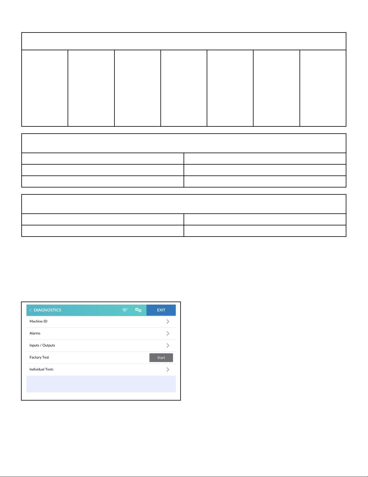
1. From the System Menu, select DIAGNOSTICS to enter the
Diagnostics Menu.
2. From the Diagnostics Menu, select MACHINE ID. The MACHINE ID display includes the machine's model and serial
number.
Figure 2
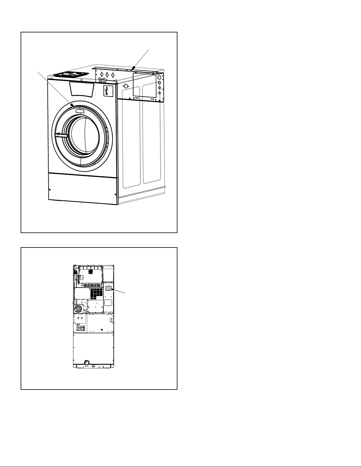
Always provide the machine’s serial number and model number
when ordering parts or when seeking technical assistance. Refer
to Figure 3 or Figure 4 .
©
Copyright, Alliance Laundry Systems LLC -
DO NOT COPY or TRANSMIT
17 Part No. F8669401ENR4
Page 18
2
1
C-CHM11P12
STX5N_SVG
1
Introduction
Model Example of Serial Plate Location
Replacement Parts
If literature or replacement parts are required, contact the source
from which the machine was purchased or contact Alliance Laundry Systems at +1 (920) 748-3950 for the name and address of
the nearest authorized parts distributor.
Customer Service
For technical assistance, contact your local distributor or contact:
Alliance Laundry Systems
Shepard Street
P.O. Box 990
Ripon, WI 54971-0990
U.S.A.
www.alliancelaundry.com
Phone: +1 (920) 748-3121 Ripon, Wisconsin
1. Serial Plate on Panel
2. Serial Plate on Door Frame
Figure 3
Stacked Washer-Extractor/Tumble Dryer Serial Plate
Location
1. Serial Plate
Figure 4
©
Copyright, Alliance Laundry Systems LLC -
DO NOT COPY or TRANSMIT
18 Part No. F8669401ENR4
Page 19
Preliminary Information
CHM2043R_SVG
Preliminary Information
About the Control
The control on the machine is an advanced, graphical, programmable computer that lets the owner control most machine features by interacting with the control.
This control allows the owner to program custom cycles, run diagnostic tests and retrieve audit and error information. Limited
programmable options can be programmed manually via the Set-
tings Menu. Full programmable options can be programmed via
IR Communications and Wi-Fi Communications.
Machines shipped from the factory have default cycles and wash
temperature settings built in. The owner can change the default
cycles or any cycle.
IMPORTANT: It is extremely important that the machine
has a positive ground and that all mechanical and electrical connections are made before applying power to
or operating the machine.
IR Communications
The control has the ability to communicate with a PC with an IrDA device running the control software. Devices such as PCs
that are IrDA capable (able to transmit information to machine)
that have been tested and approved for use with the control software can be used as a tool for managing the machine.
face device. Connection with the ALS Wi-Fi Network allows the
user to program, collect data, and run diagnostics remotely.
Audit Information
The control collects and stores audit information which can be
accessed through the touch display, IR communication or Wi-Fi
communication. Refer to the Audit Data Menu for a list of available audit information.
Using IR communication or Wi-Fi communication, the user can
receive audit and program data from the control and send programming data and diagnostic commands to the control.
IR Communications Menu
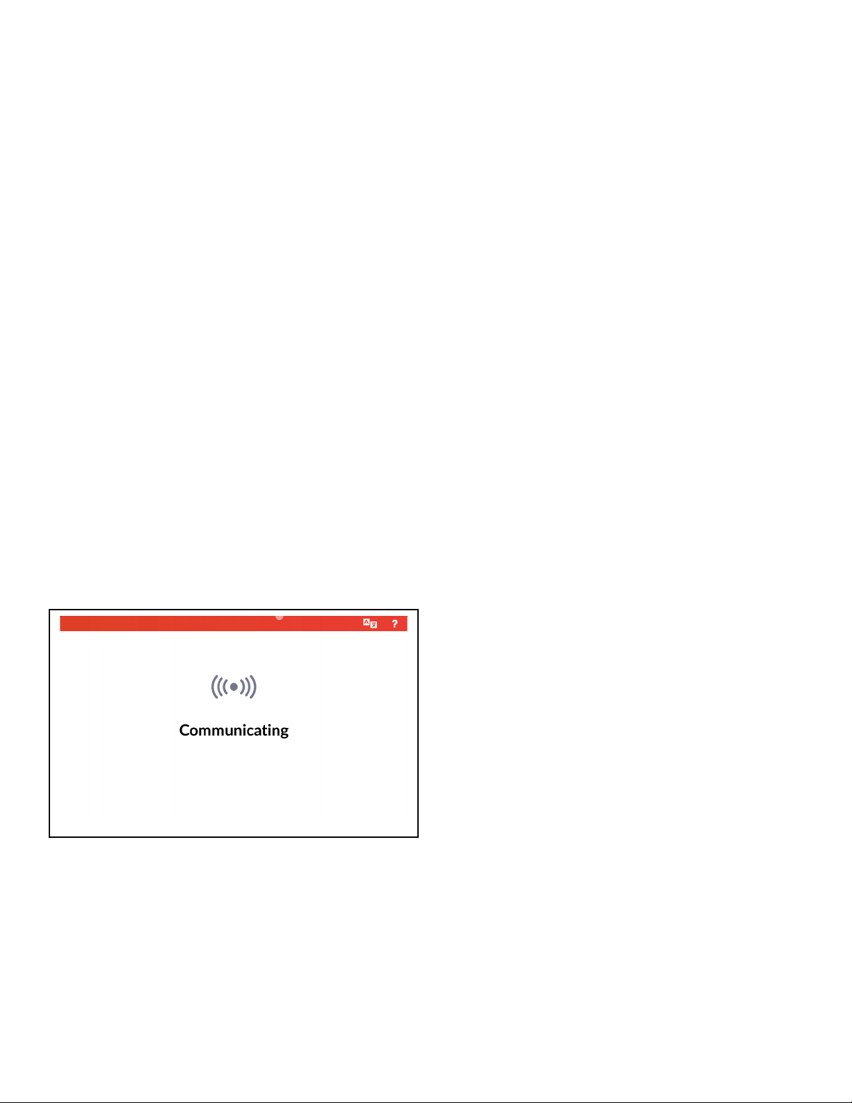
Figure 5
The IR Communications Menu displays while the control is communicating with a PC. The control will return to the previous
page when the communication is complete.
Wi-Fi Communications
The control has the ability to connect with the ALS Wi-Fi Network via an internet connection using the network gateway inter-
©
Copyright, Alliance Laundry Systems LLC -
DO NOT COPY or TRANSMIT
19 Part No. F8669401ENR4
Page 20

Special Features
Special Features
Break-In Alarm
The Break-In Alarm allows the owner to program the machine to
set a Break-In Alarm Error if the Service Door or Coin Vault is
opened without first disabling the alarm.
Cycle Time Display
The Run Menu shows the time remaining in the currently running
cycle for user convenience.
Cycle Completed Timer
If enabled in programming, a timer begins counting up in the Cycle Complete Menu since the cycle ended.
Passcode Security
If enabled in programming, this option allows the owner to require a passcode to gain access to Rapid Advance Activation, Di-
agnostics Menu, Drop Off Mode, Lockout Mode, Settings Menu,
Audit Data Menu, Reset Menu and various sub-menus.
To disable passcode protection to the System Menu, programming
through PC communication is required.
Language Selection
The control contains 34 languages. Once a language is selected,
all menus and displays will be shown in the chosen language.
Special Vend
The Special Vend option allows the owner to set a special vend
price or free vend between specific times of day, days of week,
dates, months and years. The owner can program the control for
up to eight (8) Special Vends periods. The owner can manually
program Special Vend 1 and can only enable or disable Special
Vends 2-8. Full programming of all Special Vends requires the
use of a PC. Refer to the System Menu for manual programming.
Increased Water Levels
Increased water levels is a modifier option that can be enabled/
disabled for the Cycle Modifier 1 and 2 options. Refer to Globals
Menu. If enabled, a cycle containing Prewash, Wash, or Rinse
Fill or Reuse Fill steps would ignore that programmed water level
and instead use the Increased Water Level for Prewash, Wash, or
Rinse steps.
Increased Spin Speed
Increased Spin Speed is a modifier option that can be enabled/
disabled for the Cycle Modifier 1 and 2 options. Refer to System
Menu. If enabled, a cycle containing extract steps with the spin
step label would ignore the cycle programmed spin speed and instead attempt the Increased Spin Speed parameter’s globally programmed value.
Dispense Soap
Lucky Cycle
The Lucky Cycle option allows the owner to program the machine to provide a free or reduced vend cycle to users after a programmed number of machine cycles have occurred or on certain
dates and times. Refer to Lucky Cycle Mode for more information.
Speed Cycle
Speed Cycle allows the owner to program special cycles with a
shorter total wash time to save the user time. The owner can program the Speed Cycle with distinct vend prices and functions.
Refer to Speed Cycle for more information.
This option can be programmed for machines that are equipped
with supply injection.
When the Supply Injection prompt parameter is enabled, refer to
Settings Menu, the user will be prompted to accept and pay for
external supplies with the start of a cycle. A cycle programmed
with external supply signals that would normally trigger during
cycle operation would be restricted from activating if the prompt
is enabled, unless the feature was accepted and paid for during
the prompt at the beginning of the cycle. Cycle execution should
halt during this prompt since it is dependent upon water to flush
the paid-for chemical into the basket.
©
Copyright, Alliance Laundry Systems LLC -
DO NOT COPY or TRANSMIT
20 Part No. F8669401ENR4
Page 21
Control Identification
Control Identification
Operational Touch Display
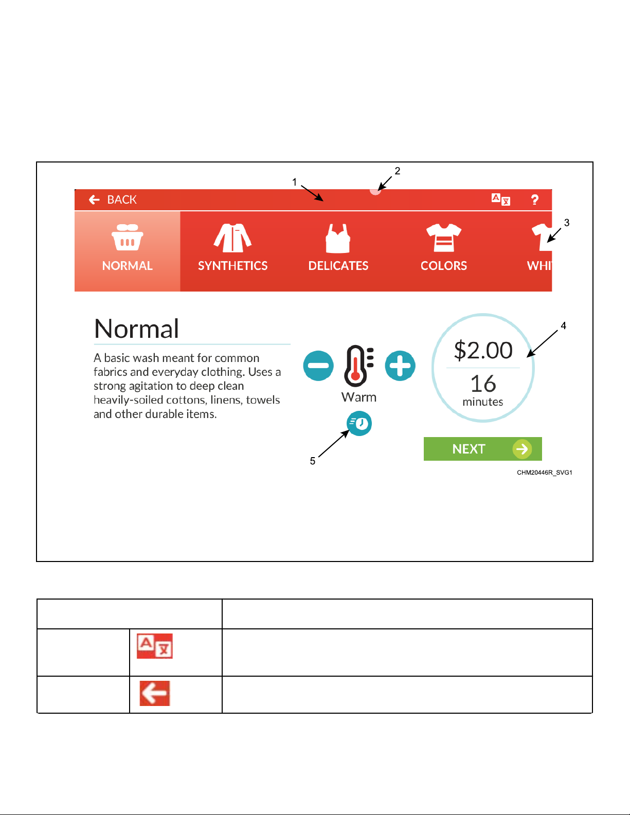
The control includes a capacitive touch display with text and
icons that are available for the operator to control and manage the
machine's operation. The primary icons used for general naviga-
tion that are available on most menus and displays are shown in
Table 1 . Additional icons and descriptions are described throughout this manual as needed. Sections of certain menu displays can
be swiped to scroll through options.
1. System Menu Access (touch and hold for 5 seconds)
2. Non-Fatal Error Indicator
3. Preset Ribbon
4. Cycle Properties/Cycle Status Ring
5. Speed Cycle Indicator
Figure 6
Icon* Description
Translate Touch to open the Language Select Panel showing the list of available languages. The
default language is at the top of the list. Selecting a different language changes all displays to that language.
Back Touch to navigate to the previously-displayed menu.
Table 1 continues...
©
Copyright, Alliance Laundry Systems LLC -
DO NOT COPY or TRANSMIT
21 Part No. F8669401ENR4
Page 22
CHM2045R_SVG
CHM2046R_SVG
Control Identification
Icon* Description
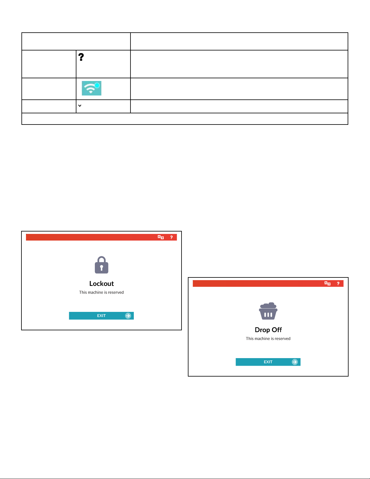
Help Touch to display the Help Menu showing (if programmed in the Settings Menu) staff
contact phone number, machine operating instructions, soap dispenser icon key and
common questions.
Wi-Fi Signal
Strength
Shows the connectivity status and signal strength of the Wi-Fi connection. This icon is
only shown in the System Menu. Touch to access Wi-Fi Settings.
Directional Arrow Indicates there is more information than what is visible on the screen.
*Not all icons are shown on every menu or display.
Table 1
Operation Modes
ters and the machine has either not received any vend or is configured for free vend. If the lockout time occurs during a cycle,
In each mode of operation, the user may touch the screen or communicate with the control to change the displayed menu.
the machine waits until the cycle ends, then enters Lockout Mode
if the time is still within the programmed time period. The control
automatically exits Lockout Mode when the Lockout Duration
Ready Mode
The control is ready for operation in Ready Mode. The control
displays the Approach Page, if enabled. If there is no user input
for 4.25 minutes, the display dims.
Lockout Mode
time has elapsed.
To exit Lockout, send a command via PC connection, program
the Lockout Duration to 0, or enter the Lockout Unlock Passcode.
The control limits access to certain features while in Lockout
Mode. Audit counters (refer to Audit Data Menu), manual programming (refer to Settings Menu) and communication via an external device (IR, network, payment system, etc) are available.
The control will also display errors as usual. The Diagnostics
Menu and Rapid Advance Activation are not available during
Lockout Mode.
Figure 7
This feature prevents the machine from being used except by a
particular user who has reserved the machine in advance. If a user
pays or reserves a machine from a kiosk or central pay system,
the machine enters Lockout Mode and the user is given a passcode to unlock the reserved machine. This guarantees that the
user does not need to wait for an available machine or risk that
the selected machine is taken after vend is added.
To access the reserved machine, touch EXIT and enter the passcode. If the passcode is entered correctly, the control displays the
Cycle Preset Page.
If programmed, the machine enters Lockout Mode when the current time falls within the time period set in the Lockout parame-
Drop Off Mode
Figure 8
This feature allows the owner to limit machine use to an attendant without requiring vend. The attendant accesses the machine
by entering the programmed Drop Off Passcode.
To access the machine in Drop Off Mode, touch EXIT and enter
the passcode. If the passcode is entered correctly, the control displays the Cycle Preset .
©
Copyright, Alliance Laundry Systems LLC -
DO NOT COPY or TRANSMIT
22 Part No. F8669401ENR4
Page 23
Control Identification
The machine enters Drop Off Mode when enabled in programming. To exit, disable Drop Off Mode in programming.
The Diagnostics Menu and Rapid Advance Activation are not
available during Drop Off Mode.
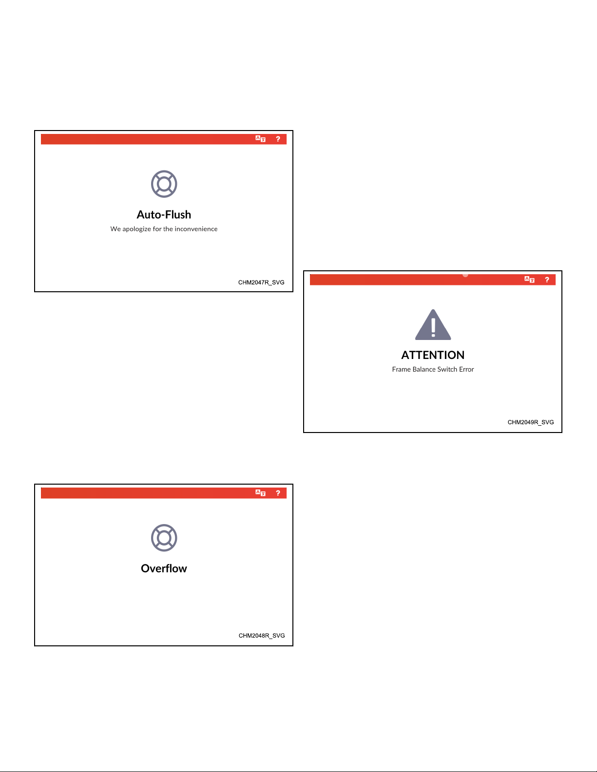
Auto-Flush Mode
Figure 9
This feature is used to periodically clean out the basket and dispenser compartments. This option is programmable through a PC
connection.
"Overflow". If disabled, the control does not display the overflow
condition.
If overflow occurs during a cycle, the cycle time pauses, water
valves and heater outputs turn off and the machine drains until
the water level is below the highest programmable water level. If
the water level drops below the overflow level within five (5) minutes of first detection and the door is locked, the cycle continues
as normal. If the control continues to see an overflow level after
five (5) minutes with the door locked, the control enters Machine
Error Mode with an Overflow Error (Fatal).
If not in a cycle, the machine drains until empty. If the door is
open or is unable to lock and the water level does not drop below
the overflow level after one (1) minute, the control enters Ma-
chine Error Mode with an Overflow Error (Fatal).
All vending inputs are ignored during this mode.
Machine Error Mode
The control enters Auto-Flush Mode on the programmed day and
time after the programmed number of cycles have occurred. The
door must be closed with no cycle running or vend added. During
Auto-Flush Mode, the control locks the door, turns of the pump
or opens the gravity drain, turns on the hot water to flush each
compartment and ignores all user inputs.
When Auto-Flush is complete, the control unlocks the door and
returns to the previous display.
Overflow Mode
Figure 11
The control enters this mode when an error is set. The control
displays the error and error information. The owner can enable
and disable certain errors and error displays as well as access to
clear errors in programming.
A notch appears in the header bar when a non-fatal error is set.
Figure 10
The control enters this mode when the control detects the water
level is too high. If enabled in programming, the display shows
©
Copyright, Alliance Laundry Systems LLC -
DO NOT COPY or TRANSMIT
23 Part No. F8669401ENR4
Page 24
CHM2051R_SVG
CHM2052R_SVG
Control Identification
Internal Control Failure
If the control detects an error in its software or hardware, all outputs are turned off and the control displays the failure. If this condition persists after an attempt to restart, then the control must be
replaced.
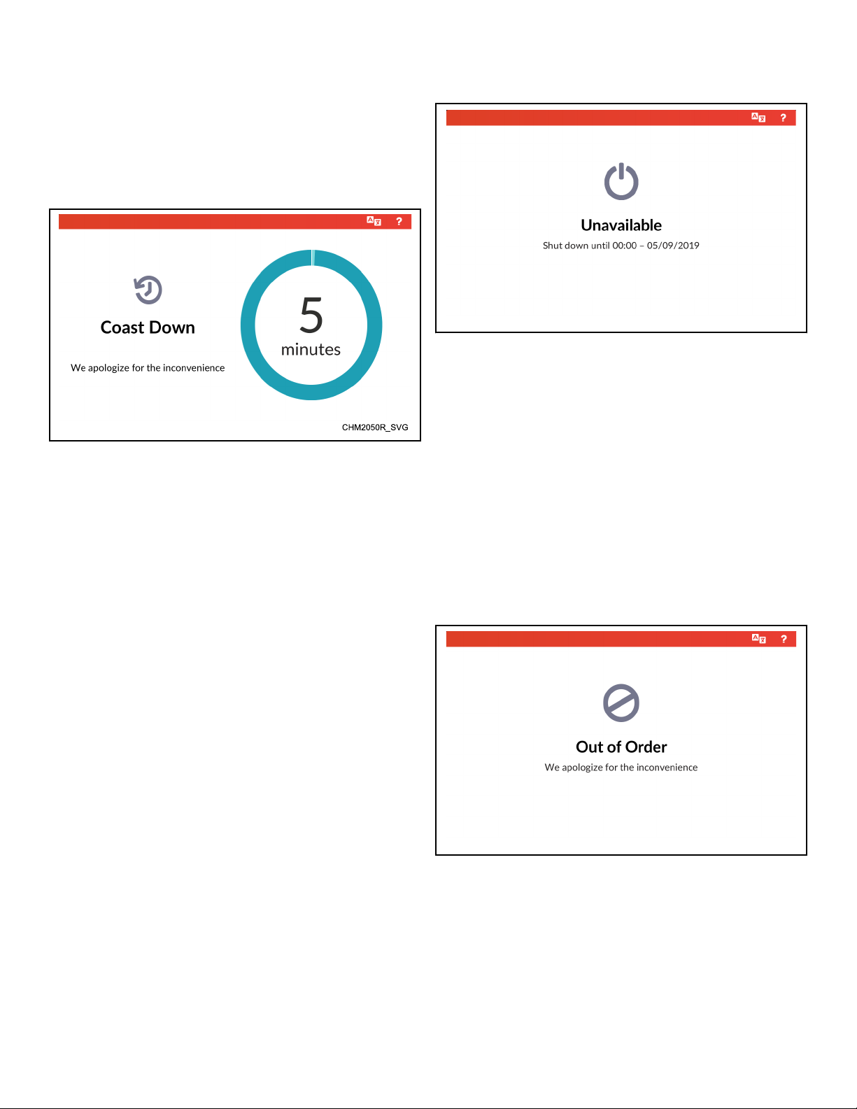
Coast Down Mode
Figure 13
The machine enters Coast Down Mode when an error or power
failure occurs during an extract cycle step. This mode allows for
adequate time to stop any spinning motion of the basket.
Shutdown Mode
Figure 14
The shutdown option allows the owner to program the machine to
enter Shutdown Mode for a certain time and date range. The control displays "Unavailable" and ignores all screen touches and
vend additions. The Language Selection Panel , Settings Menu
and Help Menu are accessible while in Shutdown Mode.
The control enters Shutdown Mode at the start date and time set
in programming and takes priority over other modes of operation.
The control remains in Shutdown Mode until the end date and
time set in programming.
The control shows the Coast Down display with a coast down
timer for five (5) minutes. If the control enters Coast Down Mode
upon power-up, the length of the power fail is subtracted from the
timer. Multiple power cycles will not reset the timer. The control
exits Coast Down Mode before the timer expires once the basket
stops spinning.
While in Coast Down Mode, the Settings Menu, Language Selec-
tion Panel and Help Menu are accessible.
If the control enters Coast Down Mode because of a power failure, the control returns to Approach Screen (if enabled) or the Cy-
cle Preset . If Coast Down Mode occurred from an error, the control enters Out of Order Mode.
The control cannot enter Shutdown Mode if running a cycle, in
Lockout Mode or if vend has been added. The control will enter
Shutdown Mode once those conditions are cleared.
Out of Order Mode
Figure 15
The owner can activate and deactivate Out of Order Mode
through the Settings Menu from the Approach Page and the Cycle
Preset Page.
©
Copyright, Alliance Laundry Systems LLC -
DO NOT COPY or TRANSMIT
The display shows "Out of Order" and "We apologize for the inconvenience" to show the the machine is unavailable. The machine will accept coins, but the vend does not count toward a cycle. The control does not allow cycles to run in this mode.
24 Part No. F8669401ENR4
Page 25

While in Out of Order Mode, the Settings Menu, Language Selection Panel and Help Menu are accessible.
Control Identification
©
Copyright, Alliance Laundry Systems LLC -
DO NOT COPY or TRANSMIT
25 Part No. F8669401ENR4
Page 26

Menu Navigation
Refer to the following charts for maps of the display menus.
Menu Navigation
©
Copyright, Alliance Laundry Systems LLC -
DO NOT COPY or TRANSMIT
26 Part No. F8669401ENR4
Page 27
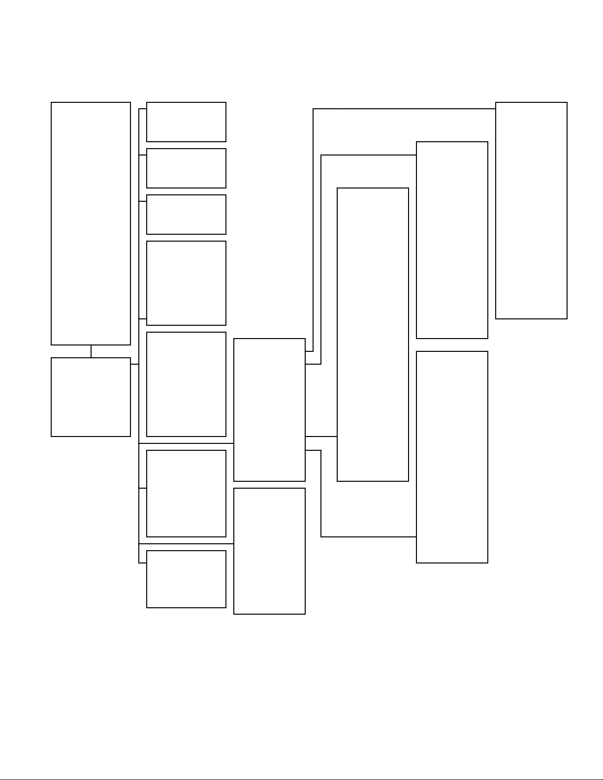
System Menu Navigation
NOTE: Refer to a specific menu section for sub-menus and additional information.
Menu Navigation
SYSTEM MENU
Rapid Advance*
Cancel Cycle
Error Presentation
Partial Vend Presentation
Settings*
Audit Data
Diagnostics*
Service Schedule
Reset*
* PASSCODE
(bypassed if disabled)
RAPID ADVANCE
Activate
CANCEL CYCLE
Cancel
ERROR PRESENT
Clear
PARTIAL VEND
PRESENT
Clear
AUDIT DATA
Machine Totals
Resettable Counters
Other Metrics
Individual Cycle
Counts
SERVICE SCHED-
ULE
Daily
Monthly
Yearly
RESET
Global Settings
Cycle Resets
SETTINGS
Vend Settings
Basic Settings
Machine Settings
Cycle Settings
DIAGNOSTICS
Machine ID
Alarms
Inputs/Outputs
Factory Test
Individual Tests
MACHINE SET-
TINGS
Machine Configuration
Approach Screen
Custom Approach
Message
Errors
Suds Removal Routine
Pocket Indicator
Heating Indicator
Temperature Display
Target Temperature
Valve Limits
Connection Settings
Modes
Output Signals
BASIC SETTINGS
Language Settings
Time and Date
Temperature Units
Speed Units
Display Settings
Audio Signal
Time Display
Cycle Complete
Timer
CYCLE SET-
TINGS
Default Cycle
Cycle Programming
Cycle Options
Global Water Temperatures
Global Water Levels
Hold Step Custom
Messages
Other Settings
Cycle Temperature
Overrides
VEND SETTINGS
Currency
Payment Settings
Vend Price Display
Override
Vend Prices
Vend Price Modifiers
Cycle Modifier Settings
Lucky Cycle
Special Vend
Pre-Clean Cycle Interval
©
Copyright, Alliance Laundry Systems LLC -
DO NOT COPY or TRANSMIT
27 Part No. F8669401ENR4
Page 28
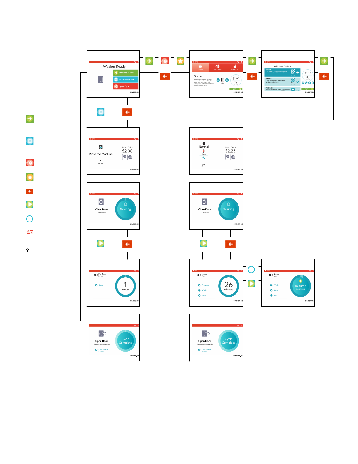
Menu Navigation
Cycle Menus Navigation (Vend Mode)
Approach Screen Cycle Preset Additional Options Menu
Navigation Key
I'm Ready to Wash/
NEXT/PAY
Rinse the Machine (if
availible)
Speed Cycle
Lucky Cycle
BACK
Payment Menu Payment Menu
Close Door Menu Close Door Menu
START/Resume
Pause
Language Selection
Panel
Help Menu
Pre-Clean Run Menu Cycle Pause Menu
Cycle Complete Menu Cycle Complete Menu
©
Copyright, Alliance Laundry Systems LLC -
DO NOT COPY or TRANSMIT
28 Part No. F8669401ENR4
Page 29
Opening the Service Door
CHM1357R_SVG
4
3
2
1
Opening the Service Door
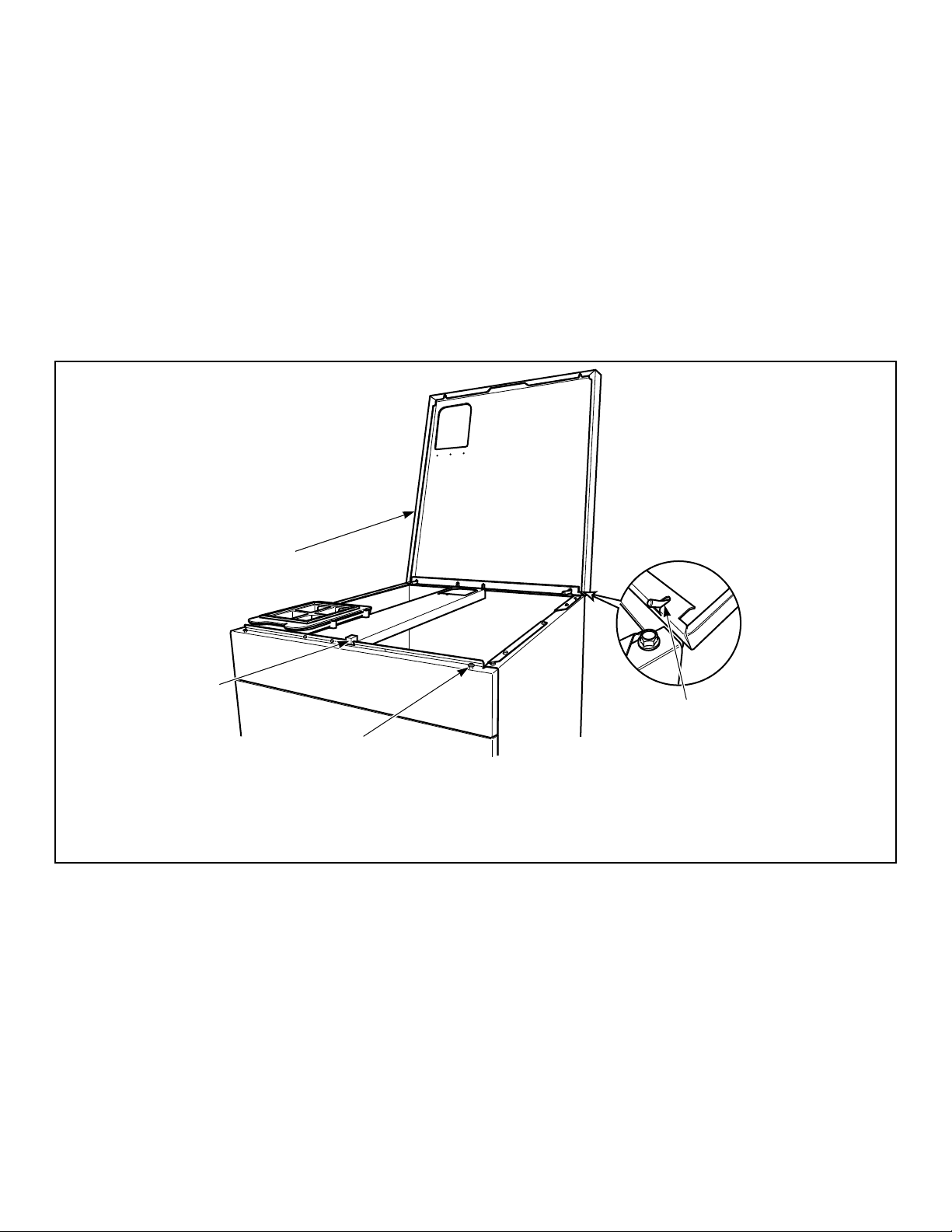
The service door, or top cover, must be opened to manually program the control. Opening the top cover 3 inches and closing it
trips a switch which allows access to various programming options.
NOTE: If the Break-In Alarm is enabled in programming,
it must be disabled before opening the top cover. For
more information on using the Break-In Alarm, refer to
the instructions included with the external device.
The top cover is located on the top of the machine.
1. Unlock the top cover.
2. Slide the top cover forward slightly to move the notches away
from the pegs on the front of the cabinet.
3. Lift the top cover up. Refer to Figure 16 .
After opening and closing the top cover, the operator has 4 minutes and 15 seconds to begin programming. If the correct passcode is not entered in that time, the control will not accept operator programming. Should this happen, open and close the top
cover again to trip the switch and allows access to the programming options.
1. Top Cover Lock
2. Top Cover
3. Top Cover Hinge
4. Peg
Stacked Washer-Extractor/Tumble Dryer
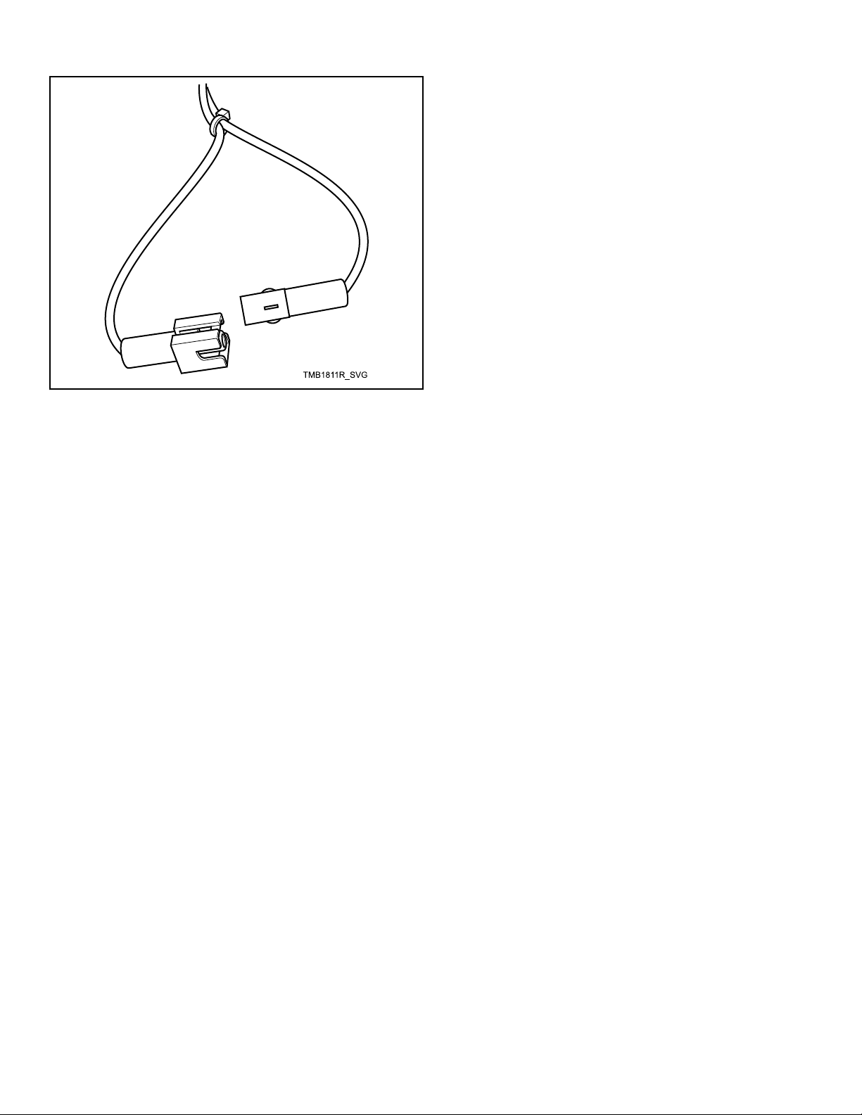
Open service door and disconnect bullet connector located between the "white/black" and "red/blue" wires for one second,
then reconnect.
©
Copyright, Alliance Laundry Systems LLC -
DO NOT COPY or TRANSMIT
Figure 16
29 Part No. F8669401ENR4
Page 30
Opening the Service Door
Figure 17
©
Copyright, Alliance Laundry Systems LLC -
DO NOT COPY or TRANSMIT
30 Part No. F8669401ENR4
Page 31
Machine Cycle Definition and Operation
Machine Cycle Definition and Operation
The control comes programmed with 15 machine cycles. The
owner can modify machine cycles or set them to "Unavailable"
by manually editing them in the Settings Menu, or through PC
connection by downloading a modified machine cycle into the
control. Machine cycles can be deleted or made "Unavailable" so
that they are not visible from the Cycle Preset or Speed Cycle.
New machine cycles can be added and existing cycles can be
copied or edited.
Refer to page 27 for an overview of menus.
Machine Cycle Operation
The control runs a cycle step by step in a sequence. If the step is
programmed to “On”, it is executed and the next step follows until the cycle is complete. Any steps programmed to “Off” are
skipped.
At the start of a cycle, the control displays a Cycle Time Countdown. This is the total time of the cycle and and modifiers. The
Cycle Time Countdown begins when the cycle starts.
Approach Screen
Figure 18
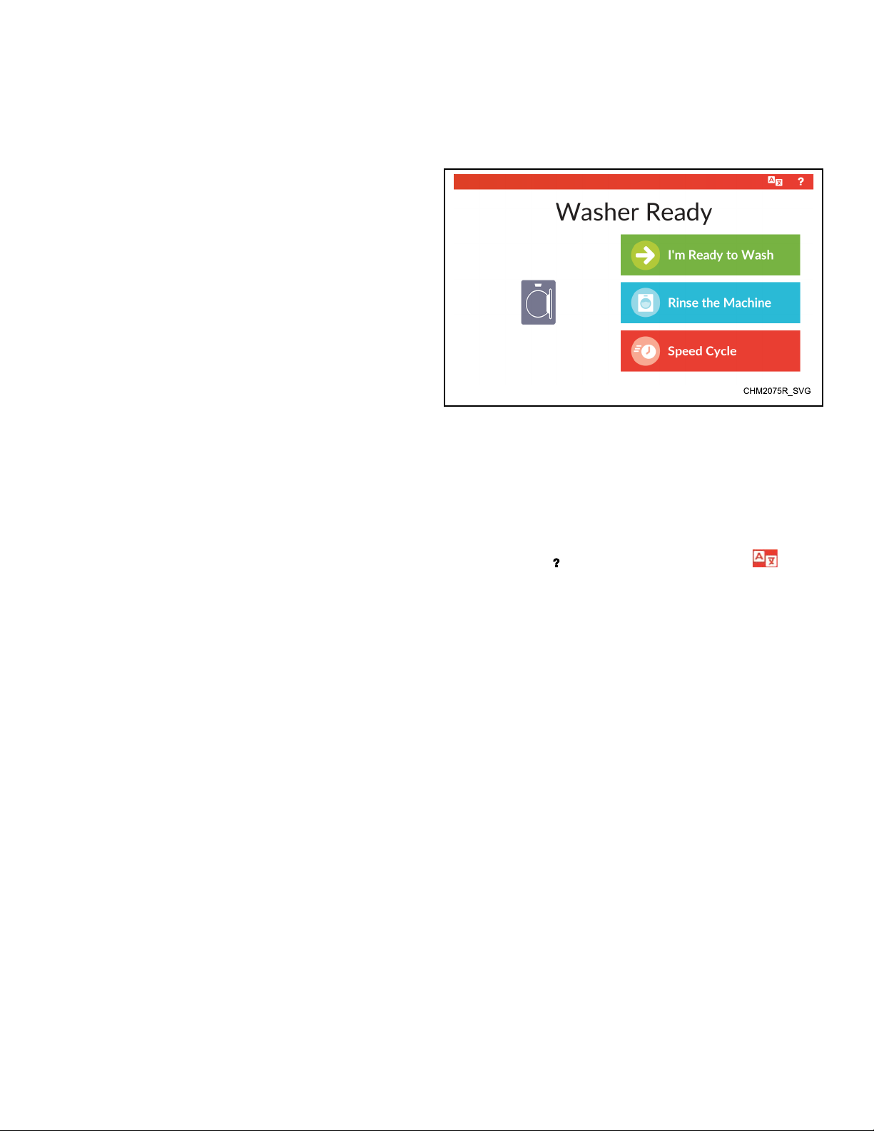
After power-up, the control automatically enters the Approach
Screen (if enabled). If programmed, this menu includes options to
access the Cycle Preset . Selecting "I'm Ready to Wash" accesses
default cycles and default cycle modifiers, selecting "Rinse the
Machine" (if availible) accesses the Pre-Clean (If Available) cy-
cle and selecting "Speed Cycle" accesses the Speed Cycle. Access
to the Help Menu ( ) and Language Selection Panel ( ) are
available on this and all other cycle selection sub-menus.
©
Copyright, Alliance Laundry Systems LLC -
DO NOT COPY or TRANSMIT
31 Part No. F8669401ENR4
Page 32
Machine Cycle Definition and Operation
Cycle Preset
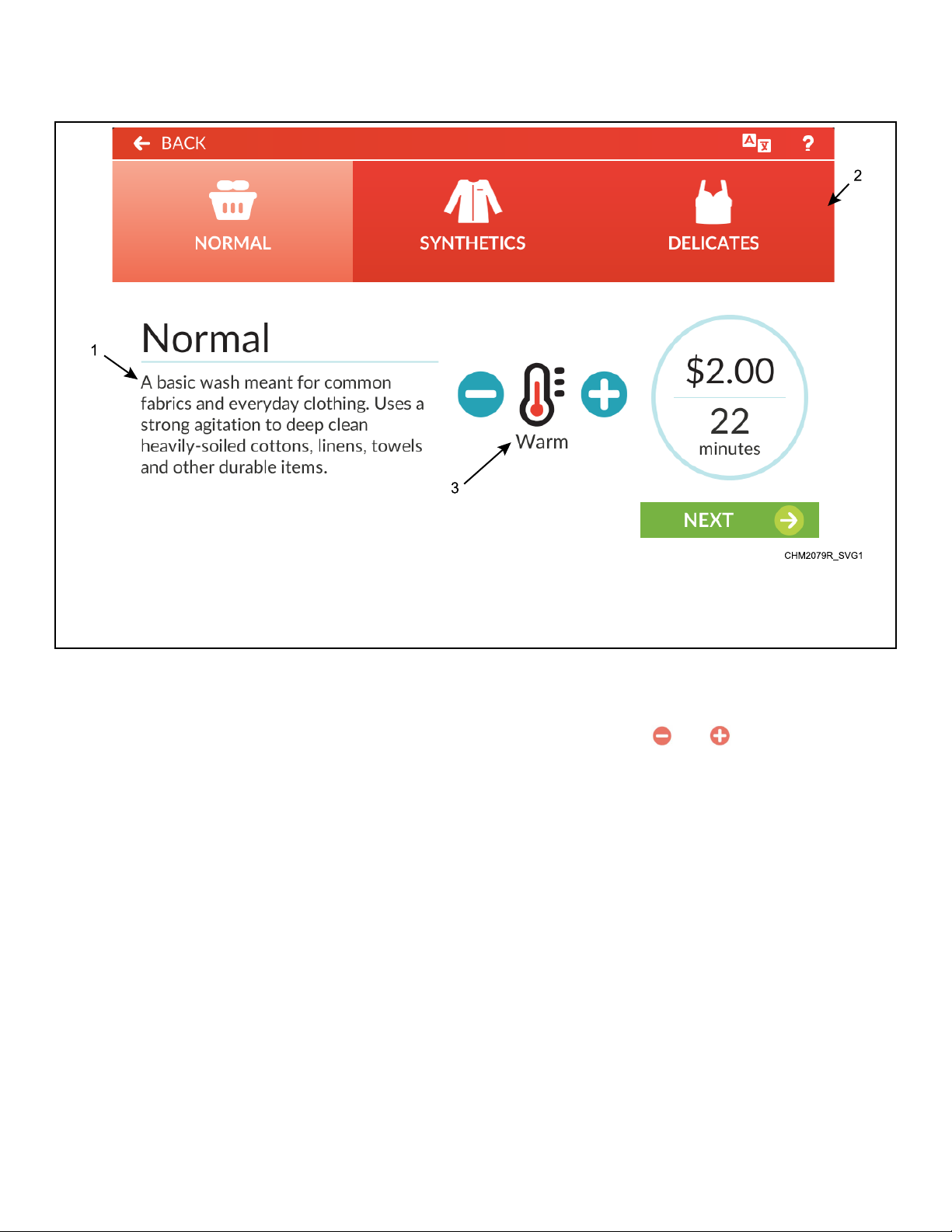
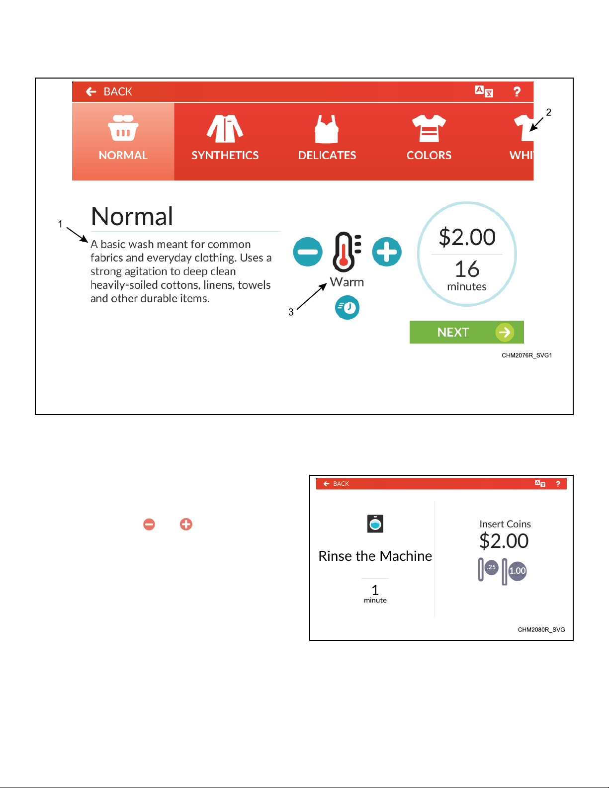
1. Cycle Description
2. Preset Ribbon (swipe to scroll)
3. Temperature Control
Figure 19
The Cycle Preset allows the user to select a preset wash cycle by
touching the icon in the preset ribbon. Machine cycles that are
programmed to "Unavailable" are not displayed in the Preset Ribbon.
The user can change the programmed water temperature setting
for any cycle by touching and on the Temperature Con-
trol.
©
Copyright, Alliance Laundry Systems LLC -
DO NOT COPY or TRANSMIT
32 Part No. F8669401ENR4
Page 33
Speed Cycle
Machine Cycle Definition and Operation
1. Cycle Properties
2. Preset Ribbon (swipe to scroll)
3. Temperature Control
Figure 20
Like the Cycle Preset , the Speed Cycle modifier allows the user
to select a preset wash cycle by touching the icon in the preset
ribbon. Speed Cycles are cycles programmed with a shorter total
wash time.
The user can change the programmed water temperature setting
for any cycle by touching and on the Temperature Con-
trol.
Pre-Clean (If Available)
Figure 21
©
Copyright, Alliance Laundry Systems LLC -
DO NOT COPY or TRANSMIT
Pre-Clean allows the user to select a rinse-only cycle to remove
any residue from the wash basket before adding laundry.
33 Part No. F8669401ENR4
Page 34
Machine Cycle Definition and Operation
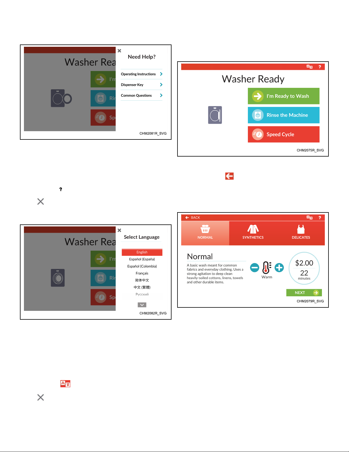
Help Menu
Figure 22
The Help Menu displays over the top of the current menu. If programmed, this menu includes staff contact phone number, machine operating instructions, soap dispenser icon key and common questions.
To access, touch in the menu header of any end-user screen.
Touch or the masked area to close the menu.
Language Selection Panel
Start a Cycle
1. From the Approach Screen, select I'm Ready to Wash, Rinse
the Machine or Speed Cycle (refer to Figure 24 ).
Figure 24
NOTE: Touch to make additional changes on a
previous menu.
2. Select a cycle from the cycle options menu Cycle Preset . Select the desired temperature, then touch NEXT (refer to Fig-
ure 25 ).
Figure 23
The Language Selection Panel displays over the top of the current
menu. This menu allows the user to select a language that will
translate all displays, including displays within the System Menu.
34 languages are available. All languages are available from the
System Menu. Only languages programmed in the Settings Menu
are available when not in System Menu.
To access, touch in the menu header of any menu display.
Touch
©
Copyright, Alliance Laundry Systems LLC -
DO NOT COPY or TRANSMIT
or the masked area to close the menu.
Figure 25
3. If programmed, select desired options from the Additional
Options Menu. The vend price and cycle time changes accordingly. When finished adding options, touch PAY (refer to
Figure 26 ). Additional options are not available on PreClean.
34 Part No. F8669401ENR4
Page 35
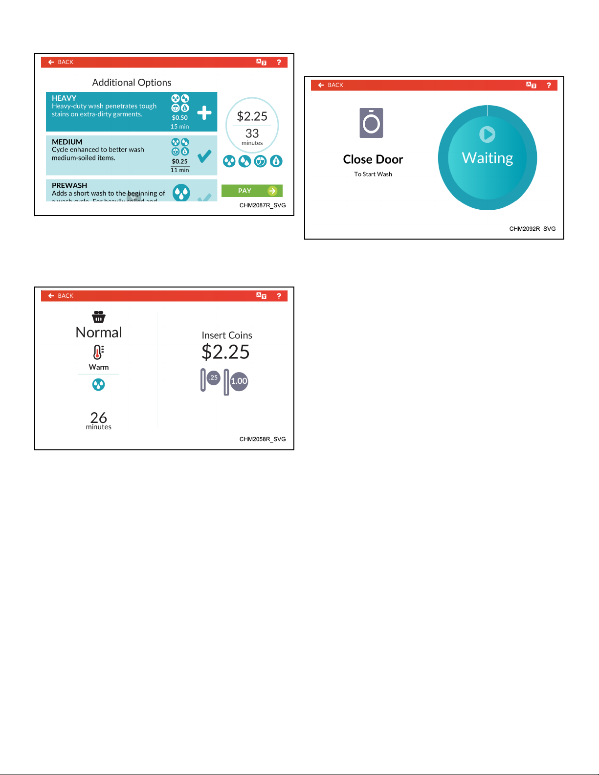
Figure 26
Machine Cycle Definition and Operation
Close Door Menu
4. The Payment Menu shows the cycle selection summary and
vend price total (refer to Figure 27 ). Once the total vend
price is entered, the vend price total changes to show START.
Figure 27
NOTE: If the door is open, the Close Door Menu
shows until the door is closed.
5. Touch START to begin the cycle.
6. The control displays the Run Menu until the cycle is complete.
Figure 28
The control displays the Close Door Menu when the loading door
is open when starting a cycle or while in a hold step. Close the
door to start or resume the cycle.
©
Copyright, Alliance Laundry Systems LLC -
DO NOT COPY or TRANSMIT
35 Part No. F8669401ENR4
Page 36
Machine Cycle Definition and Operation
Run Menu
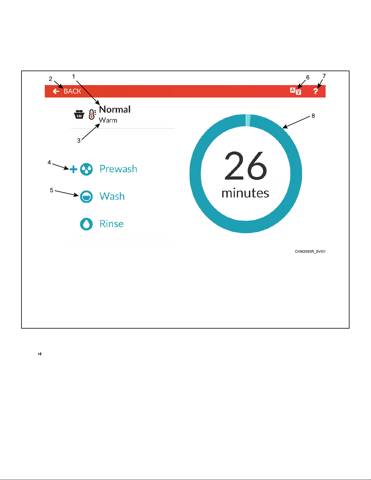
The Run Menu displays the cycle name, status, temperature, cycle step list and remaining cycle time while the cycle is in process. Refer to Figure 29 .
1. Cycle Name
2. Back (returns to the Cycle Preset )
3. Cycle Temperature
4. Added Cycle Options
5. Cycle Step
6. Language Selection Panel
7. Help Menu
8. Status Ring
Figure 29
Touch to Rapid Advance.
Touch and hold the Status Ring to pause a cycle. The display
changes to the Cycle Pause Menu .
The display shows the Cycle Complete Menu when the cycle is
complete.
©
Copyright, Alliance Laundry Systems LLC -
DO NOT COPY or TRANSMIT
36 Part No. F8669401ENR4
Page 37
Machine Cycle Definition and Operation
Cycle Pause Menu
Figure 30
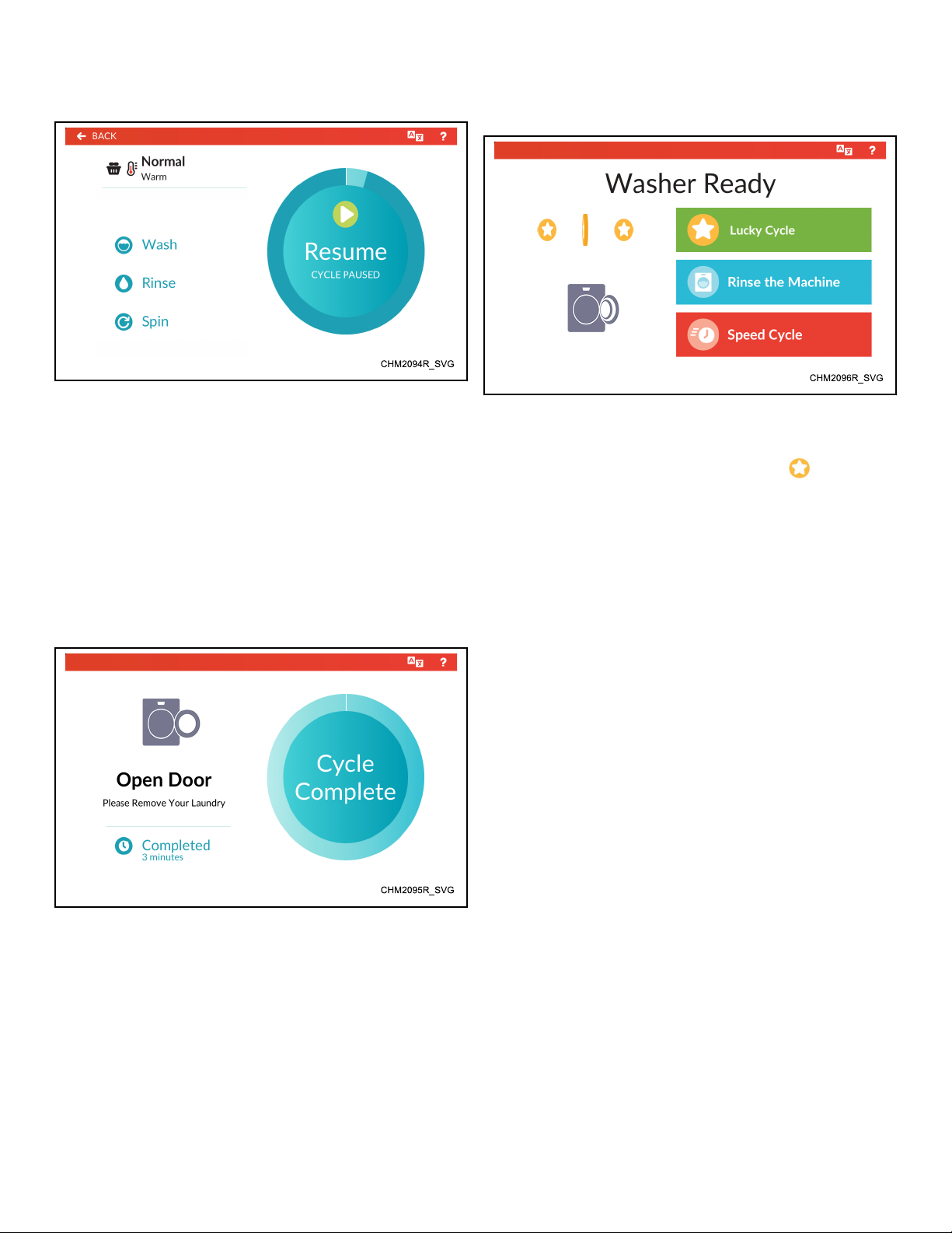
The Cycle Pause Menu displays when a running cycle is paused
in a hold step or by the user. If enabled, the user can pause a cycle by touching the middle of the Cycle Status Ring for five (5)
seconds during the first three (3) minutes of a running cycle before the first Fill Step is complete ( Rapid Advance Activation
must not be active). A cycle can also be paused via PC connection.
Touch "Resume" to resume the current cycle. The display returns
to the Run Menu .
Cycle Complete Menu
Lucky Cycle Mode
Figure 32
When the control rewards a Lucky Cycle, the current Approach
Page menu displays "Lucky Cycle" and/or the
winning user can select a cycle, add options and add vend (if the
cycle is not programmed to free) as usual.
The control triggers a Lucky Cycle and resets the counter once the
control runs the programmed number of cycles on a programmed
date and time. The control will not reward the winning cycle until
either 4.25 minutes have passed since the end of the last cycle or
the control displays the winning cycle on the initial vend attempt,
depending on programming.
icon. The
Figure 31
The Cycle Complete Menu displays when the machine reaches
the end of a cycle .
The Cycle Complete Menu shows "Cycle Complete" when a cycle completes. If enabled in programming, the display also shows
the time since the cycle completion.
The control returns to Approach Page when the user opens the
loading door.
The Lucky Cycle takes priority over Special Vends and Standard
Vend pricing. If the user selects a different cycle within the allotted time for a cycle change, the control runs the newly selected
cycle. If equipped with a serial payment system, it is up to the
payment system to honor or ignore the Lucky Cycle.
©
Copyright, Alliance Laundry Systems LLC -
DO NOT COPY or TRANSMIT
37 Part No. F8669401ENR4
Page 38
Manual Programming
CHM2098R_SVG
Manual Programming
Refer to page 26 for an overview of menus.
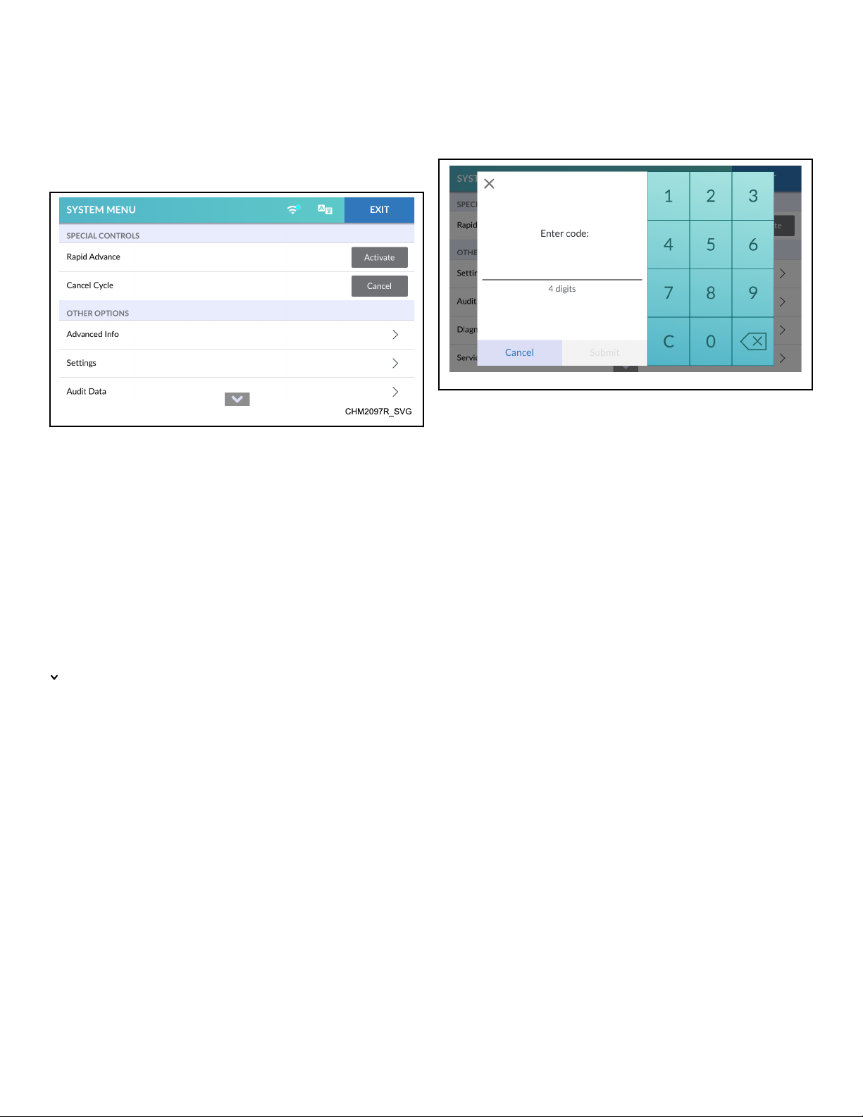
System Menu
Figure 33
The System Menu allows the user to access RAPID ADVANCE
( Rapid Advance Activation), CANCEL CYCLE ( Cancel Cycle),
ERROR PRESENT ( Clear Active Error ), PARTIAL VEND
PRESENT ( Clear Partial Vend ), ADVANCED INFO ( Ad-
vanced Info Menu), SETTINGS ( Settings Menu), AUDIT DATA
( Audit Data Menu), DIAGNOSTICS ( Diagnostics Menu),
SERVICE SCHEDULE ( Service Schedule Menu) and RESET
( Reset Menu).
To access the System Menu, press and hold for 3 seconds on the
center of the menu header from the display with the service door
open and, for coin models, the coin vault closed .
Passcode Menu
Figure 34
The owner can program the control to require users to enter a
passcode to access sections of the System Menu. The control displays the Passcode Menu when entering RAPID ADVANCE
( Rapid Advance Activation), SETTINGS (Settings Menu), DIAGNOSTICS (Diagnostics Menu) or RESET (Reset Menu) submenus from the System Menu.
1. Enter the four (4) digit passcode by touching the numbers on
the display.
2. Touch SUBMIT on the touchscreen to access the selected Sys-
tem Menu sub-menu.
indicates there is more content than fits on the screen. Swipe up
or down to see all content.
Touch EXIT to return to the previous screen.
NOTE: When selecting RAPID ADVANCE, DIAGNOSTICS, RESET or SETTINGS, the Passcode Menu will appear first, if programmed to be passcode protected.
©
Copyright, Alliance Laundry Systems LLC -
DO NOT COPY or TRANSMIT
38 Part No. F8669401ENR4
Page 39
Save Changes Menu
CHM2099R_SVG
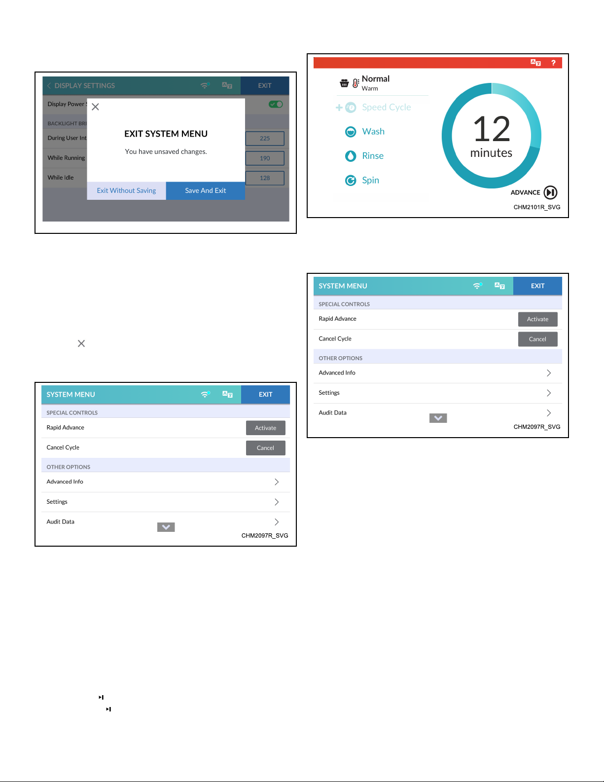
Figure 35
After modifications are complete, touch EXIT to access the Save
Changes Menu.
• Touch SAVE AND EXIT to save changes and exit the current
menu.
• Touch EXIT WITHOUT SAVING to discard changes and exit
the current menu.
•
Touch to return to the current menu and continue making
changes.
Rapid Advance Activation
Manual Programming
Figure 37
Cancel Cycle
Figure 36
1. To access, touch and hold the center of the menu header on
the display with the service door open and, for coin models,
the coin vault closed. The control enters the System Menu.
2. Touch Activate next to RAPID ADVANCE.
3. If the option is passcode protected in programming, enter the
passcode in the Passcode Menu. Activate changes to "Active"
to indicate the Rapid Advance option is active.
4. When finished activating Rapid Advance, touch EXIT to exit
the System Menu.
5. ADVANCE shows in the lower right corner of the Run
Menu . Touch to advance to the next cycle step.
Figure 38
1. To access, touch and hold the center of the menu header on
the display with the service door open and, for coin models,
the coin vault closed. The control enters the System Menu.
2. Touch CANCEL next to CANCEL CYCLE to end the cycle
and hide the option.
3. When finished, touch EXIT to exit the System Menu.
©
Copyright, Alliance Laundry Systems LLC -
DO NOT COPY or TRANSMIT
39 Part No. F8669401ENR4
Page 40
Manual Programming
Clear Active Error
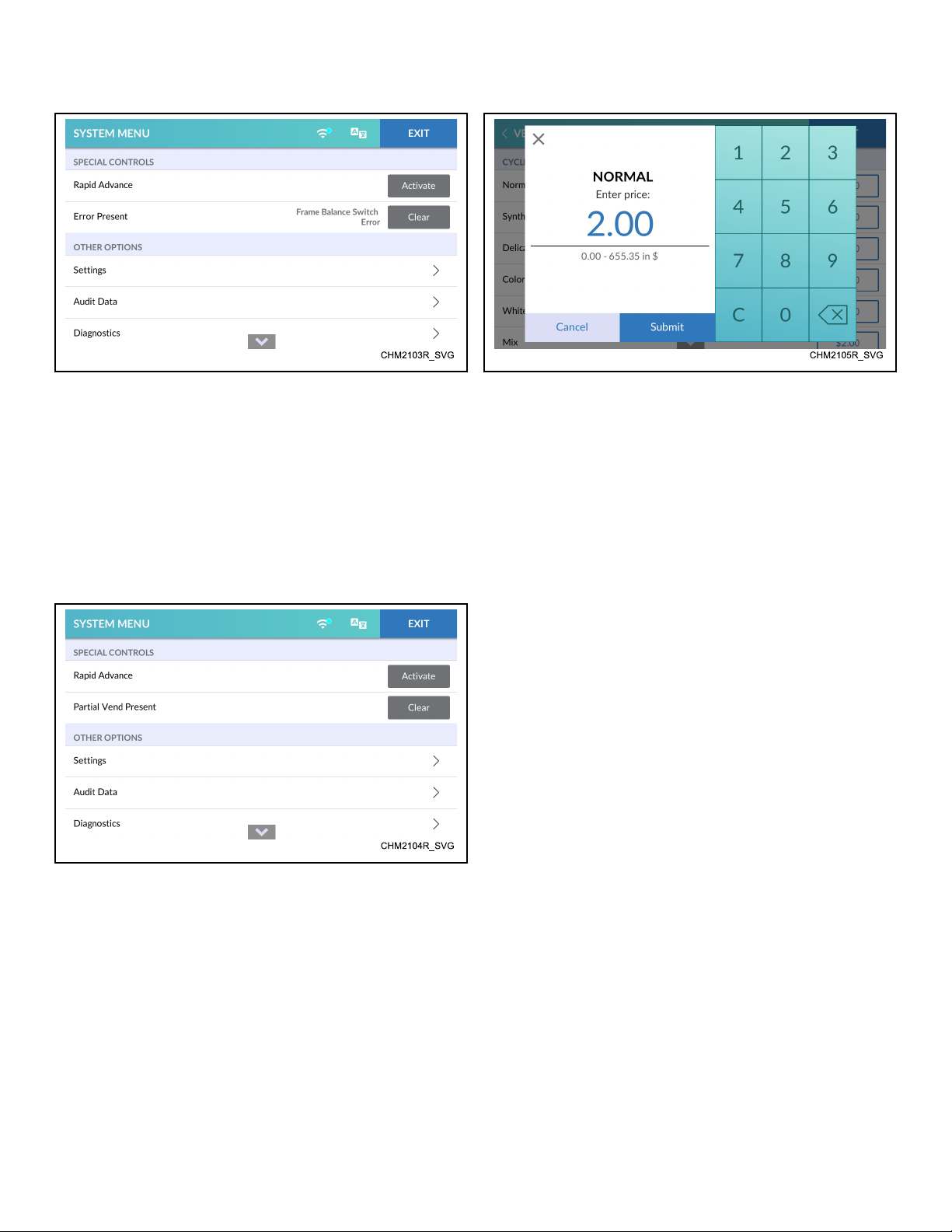
Figure 39
1. To access, touch and hold the center of the menu header on
the display with the service door open and, for coin models,
the coin vault closed. The control enters the System Menu.
2. Touch Clear next to ERROR PRESENT to clear the error.
This option only shows if errors are present.
3. When finished clearing the error, touch EXIT to exit the Sys-
tem Menu.
Clear Partial Vend
Change Vend Price
Figure 41
1. To access, touch and hold the center of the menu header on
the display with the service door open and, for coin models,
the coin vault closed. The control enters the System Menu.
2. Touch SETTINGS, then VEND SETTINGS and navigate to
Vend Prices.
3. Touch the vend price next to the desired cycle to change.
4. Touch "C" to clear the current vend price.
5. Enter the new vend price using the keypad. Touch SUBMIT.
6. When finished changing the cycle price, touch EXIT to exit
the System Menu.
7. Touch SAVE AND EXIT.
Figure 40
1. To access, touch and hold the center of the menu header on
the display with the service door open and, for coin models,
the coin vault closed. The control enters the System Menu.
2. Touch Clear next to PARTIAL VEND PRESENT to clear the
entered vend and hide the option.
NOTE: Any cleared vend will be added to the Audit
Data Menu.
3. When finished clearing the vend, touch EXIT to exit the System Menu.
©
Copyright, Alliance Laundry Systems LLC -
DO NOT COPY or TRANSMIT
40 Part No. F8669401ENR4
Page 41
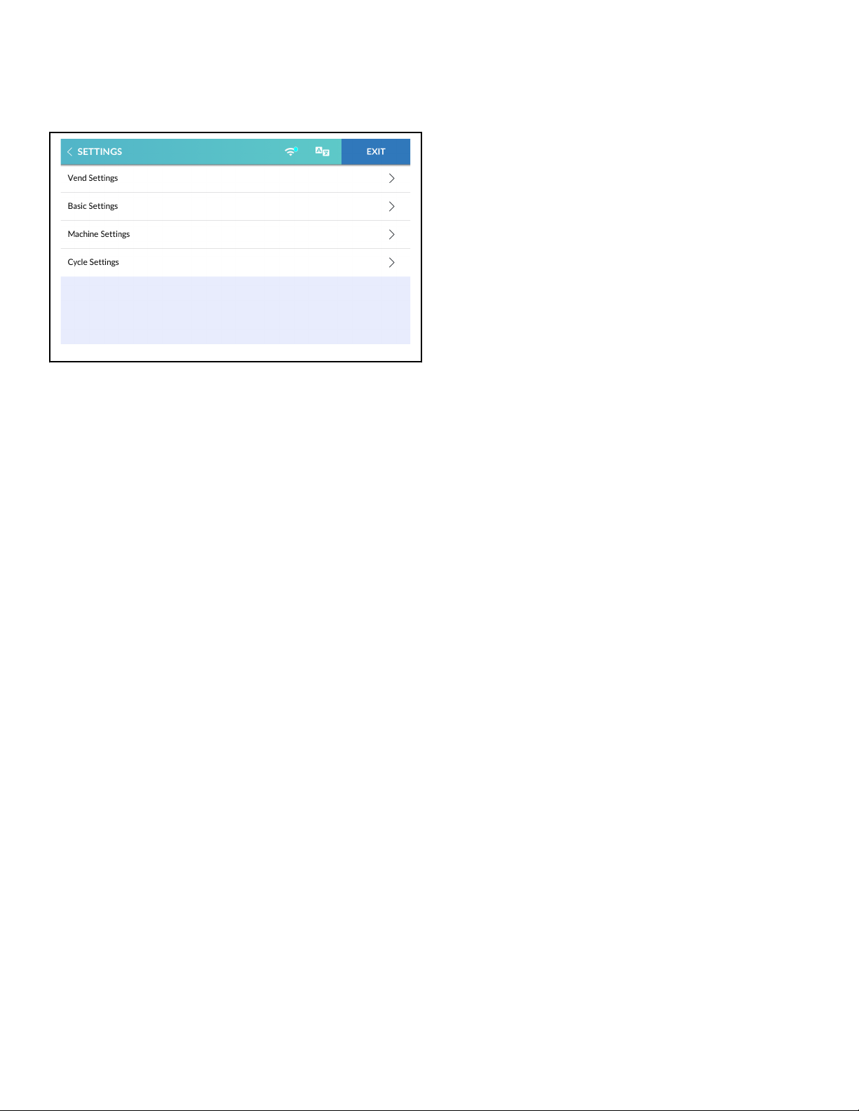
Settings Menu
CHM2107R_SVG
Figure 42
The Settings Menu allows the owner to adjust the global settings
of the control. Refer to Table 2 , Table 3 , Table 4 and Table 5 for
setting options in each sub-menu.
1. To access, touch and hold the center of the menu header on
the display with the service door open and, for coin models,
the coin vault closed. The control enters the System Menu.
2. Touch SETTINGS from the display to enter the Settings
Menu.
3. When finished making changes, touch SETTINGS to return to
the System Menu or EXIT to exit the System Menu.
Settings Menu
©
Copyright, Alliance Laundry Systems LLC -
DO NOT COPY or TRANSMIT
41 Part No. F8669401ENR4
Page 42
Settings Menu
Vend Settings
Default values marked as * are customized at the factory according to the machine's specific market and model.
VEND SETTINGS
Display Description Default
Currency Set the monetary configuration on the display.
Monetary Unit 1
Symbol
Select One No Symbol
$ Dollar
£ Pound
¥ Yen
₩ Won
€ Euro
₹ Rupee
₤ Turkish Lira
Ruble
Ft Forint
Kč Koruna
Kr Krona
Kn Kuna
R Rand
R$ Real
Tk Token
Zł Złoty
*
Symbol Placement Before/After *
Vend Price Separator 00000
Preview Preview the currency configuration. -
©
Copyright, Alliance Laundry Systems LLC -
DO NOT COPY or TRANSMIT
*
0000.0
000.00
00.000
0000,0
000,00
00,000
Table 2 continues...
42 Part No. F8669401ENR4
Page 43
VEND SETTINGS
Display Description Default
Payment Settings Set the payment method.
Enable Types
Coin Enable/Disable *
Coin Options Single/Dual/Electronic *
Coin Values
Coin 1 Value 1 - 65535 *
Coin 2 Value 1 - 65535 *
Electronic Drop(s) Display Configuration
Settings Menu
Displayed Values - Cur-
If set to 1-4, coins show as currency. If set to 5, 1-5 show as tokens.
rency 1
Number of Coins 1-5 *
Coin 1-5 Blank/Token, 1-65535 *
Card Reader Enable/Disable *
Kiosk Enable/Disable, 0-255 *
Mobile Enable/Disable *
Bill Enable/Disable *
Serial / Pulse Interface
Serial Payment System Enable/Disable *
Start Pulse Mode Disabled/Single Pulse/Multiple Pulses *
Start Pulse Value 1-65535 *
Vend Price Display Override Enable/Disable Disable
Vend Prices Set the vend price for each cycle.
Table 2 continues...
©
Copyright, Alliance Laundry Systems LLC -
DO NOT COPY or TRANSMIT
43 Part No. F8669401ENR4
Page 44
Settings Menu
Cycles
Normal 0-65535 200
Synthetics 0-65535 200
Delicates 0-65535 200
Colors 0-65535 200
Whites 0-65535 200
Mix 0-65535 200
Woolens 0-65535 200
Delicates 0-65535 200
Bedding 0-65535 200
Hot Wash 0-65535 200
VEND SETTINGS
Display Description Default
Warm Wash 0-65535 200
Cotton 0-65535 200
High Speed Spin 0-65535 200
Pre-Clean (if availible) 0-65535 200
Custom Cycle 0-65535 200
Vend Price Modifiers Set the vend price for each modifier.
Bundles
Medium Soil
0-65535 50
Deluxe Wash
Custom Bundle 1
Heavy Soil
0-65535 50
Ultra Wash
Custom Bundle 2
Table 2 continues...
©
Copyright, Alliance Laundry Systems LLC -
DO NOT COPY or TRANSMIT
44 Part No. F8669401ENR4
Page 45
VEND SETTINGS
Display Description Default
INDIVIDUALS
Dispense Soap 0-65535 50
Ozone 0-65535 50
Modifier 1 0-65535 50
Modifier 2 0-65535 50
Water Level 0-65535 50
Extra Time 0-65535 50
Warm Rinse 0-65535 50
Spin Speed 0-65535 50
Speed Cycle 0-65535 50
Temperature Adjustments
Settings Menu
Warm * 0-65535 50
Hot ** 0-65535 50
59F [15C] 0-65535 50
86F [30C] 0-65535 50
104F [40C] 0-65535 50
122F [50C] 0-65535 50
140F [60C] 0-65535 50
194F [90C] 0-65535 50
Cycle Modifier Settings Set cycle overrides for each modifier.
Modifier Bundle Names
Select One Medium Soil, Heavy Soil
Deluxe Wash, Ultra Wash
Custom Bundle 1, Custom Bundle 2
Default Included Modifiers
Table 2 continues...
©
Copyright, Alliance Laundry Systems LLC -
DO NOT COPY or TRANSMIT
45 Part No. F8669401ENR4
Page 46
Settings Menu
VEND SETTINGS
Display Description Default
Include Bundle None OR Medium Soil OR Heavy Soil
Individuals
Dispense Soap Enable/Disable Enable
Ozone Enable/Disable Enable
Modifier 1 * Enable/Disable Enable
Modifier 2 ** Enable/Disable Enable
Water Level Enable/Disable Enable
Extra Time Enable/Disable Enable
Warm Rinse Enable/Disable Enable
Spin Speed Enable/Disable Enable
Speed Cycle Enable/Disable Enable
Bundles
Medium Soil Options
-
None OR Deluxe Wash OR Ultra Wash
None OR Custom Bundle 1 OR Custom Bundle
2
Enable/Disable -
Deluxe Wash Options
Custom Bundle 1 Options
Display Name Keypad (20 characters) "Custom 2"
Description Keypad (20 characters) "Custom 2"
Included Modifiers
Modifier 1 * Enable/Disable Disable
Modifier 2 ** Enable/Disable Disable
Water Level Enable/Disable Disable
Extra Time Enable/Disable Disable
Extra Wash Time 0-15 2
Extra Rinse Time 0-15 2
Warm Rinse Enable/Disable Disable
Spin Speed Enable/Disable Disable
Table 2 continues...
©
Copyright, Alliance Laundry Systems LLC -
DO NOT COPY or TRANSMIT
46 Part No. F8669401ENR4
Page 47
Settings Menu
VEND SETTINGS
Display Description Default
Heavy Soil Options
Enable/Disable -
Ultra Wash Options
Custom Bundle 2 Options
Display Name Keypad (20 characters) "Custom 2"
Description Keypad (20 characters) "Custom 2"
Included Modifiers
Modifier 1 * Enable/Disable Disable
Modifier 2 ** Enable/Disable Disable
Water Level Enable/Disable Disable
Extra Time Enable/Disable Disable
Extra Wash Time 0-15 4
Extra Rinse Time 0-15 4
Warm Rinse Enable/Disable Disable
Spin Speed Enable/Disable Disable
Individuals
Dispense Soap Enable/Disable -
Ozone Enable/Disable -
Modifier 1 * Enable/Disable -
Modifier 2 ** Enable/Disable -
Water Level Enable/Disable -
Extra Time Enable/Disable -
Extra Wash Time 0-15 -
Extra Rinse Time 0-15 -
Warm Rinse Enable/Disable -
Spin Speed Enable/Disable -
Speed Cycle Enable/Disable -
Modifier Settings
Water Level
Prewash / Wash 1-30/Low/Medium/High -
Rinse 1-30/Low/Medium/High -
Table 2 continues...
©
Copyright, Alliance Laundry Systems LLC -
DO NOT COPY or TRANSMIT
47 Part No. F8669401ENR4
Page 48
Settings Menu
VEND SETTINGS
Display Description Default
Spin Speed Very Low/Low/Medium/High/Very High/Ultra
High/Custom RPM or g-force
Lucky Cycle Set lucky cycle parameters.
Days Enabled Sunday-Saturday None
Number of Cycles Between 1-255 50
Display Option After Input/After Delay After Input
Active Dates
Start Time 0:00-23:59 0:00
Length 1-24 hours 24
Active Dates
Limited Dates Enable/Disable Disable
Start Month 1-12/Disable Disable
Start Date 1-31/Disable Disable
End Month 1-12/Disable Disable
End Date 1-31/Disable Disable
Limited Annually Enable/Disable Disable
-
Start Year '00-'99/Disable Disable
End Year '00-'99/Disable Disable
Special Vend Set parameters for special vend time slots.
Special Vend 1 Enable/Disable Disable
Table 2 continues...
©
Copyright, Alliance Laundry Systems LLC -
DO NOT COPY or TRANSMIT
48 Part No. F8669401ENR4
Page 49
Settings Menu
VEND SETTINGS
Display Description Default
Days Enabled Sunday-Saturday None
Active Times
Start Time 0:00-23:59 0:00
Length 1-24 hours 1
Active Dates
Limited Dates Enable/Disable Disable
Start Month January-December/Disable Disable
Start Date 0-31 0
End Month January-December/Disable Disable
End Date 0-31 0
Repeat Annually Enable/Disable Disable
Start Year 0-99 0
End Year 0-99 0
Settings
Special Vend 1 Prices
Cycles
Normal 0-65535 0
Synthetics 0-65535 0
Delicates 0-65535 0
Colors 0-65535 0
Whites 0-65535 0
Mix 0-65535 0
Woolens 0-65535 0
Delicates 0-65535 0
Bedding 0-65535 0
Hot Wash 0-65535 0
Warm Wash 0-65535 0
©
Copyright, Alliance Laundry Systems LLC -
DO NOT COPY or TRANSMIT
Cotton 0-65535 0
High Speed Spin 0-65535 0
Pre-Clean (if availible) 0-65535 0
Custom Cycle 0-65535 0
Table 2 continues...
49 Part No. F8669401ENR4
Page 50
Settings Menu
VEND SETTINGS
Display Description Default
Special Vend 1 Price Modifiers
Bundles
Medium Soil
0-65535 0
Deluxe Wash
Custom Bundle 1
Heavy Soil
0-65535 0
Ultra Wash
Custom Bundle 2
Individuals
Dispense Soap 0-65535 0
Ozone 0-65535 0
Modifier 1 * 0-65535 0
Modifier 2 ** 0-65535 0
Water Level 0-65535 0
Extra Time 0-65535 0
Warm Rinse 0-65535 0
Spin Speed 0-65535 0
Speed Cycle 0-65535 0
Temperature Adjustments
Warm 0-65535 0
Hot 0-65535 0
59°F [15°C] 0-65535 0
86°F [30°C] 0-65535 0
104°F [40°C] 0-65535 0
122°F [50°C] 0-65535 0
140°F [60°C] 0-65535 0
194°F [90°C] 0-65535 0
Special Vend 1 Modifier Settings
Special Vend 1 Default Included Modifiers
Table 2 continues...
©
Copyright, Alliance Laundry Systems LLC -
DO NOT COPY or TRANSMIT
50 Part No. F8669401ENR4
Page 51
Settings Menu
VEND SETTINGS
Display Description Default
Include Bundle Medium Soil and Heavy Soil
Individuals
Dispense Soap Enable/Disable -
Ozone Enable/Disable -
Modifier 1 * Enable/Disable -
Modifier 2 ** Enable/Disable -
Water Level Enable/Disable -
Extra Time Enable/Disable -
Warm Rinse Enable/Disable -
Spin Speed Enable/Disable -
Speed Cycle Enable/Disable -
Medium Soil Options
Deluxe Wash Options
Custom Bundle 1 Options
-
Deluxe Wash and Ultra Wash
Custom Bundle 1 and Custom Bundle 2
-
Included Modifiers
Modifier 1 * Enable/Disable -
Modifier 2 ** Enable/Disable -
Water Level Enable/Disable -
Extra Time Enable/Disable -
Warm Rinse Enable/Disable -
Spin Speed Enable/Disable -
Heavy Soil Options
Ultra Wash Options
Custom Bundle 2 Options
Table 2 continues...
-
©
Copyright, Alliance Laundry Systems LLC -
DO NOT COPY or TRANSMIT
51 Part No. F8669401ENR4
Page 52
Settings Menu
VEND SETTINGS
Display Description Default
Included Modifiers
Modifier 1 * Enable/Disable -
Modifier 2 ** Enable/Disable -
Water Level Enable/Disable -
Extra Time Enable/Disable -
Warm Rinse Enable/Disable -
Spin Speed Enable/Disable -
Individuals
Dispense Soap Enable/Disable -
Ozone Enable/Disable -
Modifier 1 * Enable/Disable -
Modifier 2 ** Enable/Disable -
Water Level Enable/Disable -
Extra Time Enable/Disable -
Warm Rinse Enable/Disable -
Spin Speed Enable/Disable -
Speed Cycle Enable/Disable -
Added Wash Time 0-10 minutes
Subtracted Wash Time 0-10 minutes
Extract Speed Limit Very Low/Low/Medium/High/Very High/Ultra
High/Custom RPM or g-force
Special Vend 2 Enable/Disable Disable
Special Vend 3 Enable/Disable Disable
Special Vend 4 Enable/Disable Disable
Special Vend 5 Enable/Disable Disable
Special Vend 6 Enable/Disable Disable
Special Vend 7 Enable/Disable Disable
Special Vend 8 Enable/Disable Disable
Pre-Clean Cycle Interval (if availible) No limit/1-127 2
* Prewash by default.
** Extra Rinse by default.
Table 2
©
Copyright, Alliance Laundry Systems LLC -
DO NOT COPY or TRANSMIT
52 Part No. F8669401ENR4
Page 53
Language Settings
Default Language Set the language that appears on all displays by
Settings Menu
Basic Settings
BASIC SETTINGS
Display Description Default
default.
Table 3 continues...
©
Copyright, Alliance Laundry Systems LLC -
DO NOT COPY or TRANSMIT
53 Part No. F8669401ENR4
Page 54
Settings Menu
BASIC SETTINGS
Display Description Default
Select One English
Español (España)
Español (Colombia)
Français
简体中文
繁體中文
Pусский
Deutsch
日本語
Italiano
Portuguêse (Portugal)
Portuguêse (Brasil)
한국어
Nederlands
Čeština
Suomi
Dansk
English
Svenska
Norsk
Polsk
Slovenščina
Română
Hrvatski
Magyar
Latviešu
Lietuvių kalba
Slovenčina
ελληνικά
български
Türkçe
Bahasa Indonesia
Bahasa Melayu
ภาษาไทย
Tiếng Việt
©
Copyright, Alliance Laundry Systems LLC -
DO NOT COPY or TRANSMIT
Table 3 continues...
54 Part No. F8669401ENR4
Page 55
BASIC SETTINGS
Display Description Default
Available Languages Languages set to "Enable" show in the Language
Selection Panel .
English Enable/Disable Enable
Español (España) Enable/Disable Enable
Español (Colombia) Enable/Disable Enable
Français Enable/Disable Enable
简体中文 Enable/Disable Enable
繁體中文 Enable/Disable Enable
Pусский Enable/Disable Enable
Deutsch Enable/Disable Enable
日本語 Enable/Disable Enable
Italiano Enable/Disable Enable
Settings Menu
Portuguêse (Portugal) Enable/Disable Enable
Portuguêse (Brasil) Enable/Disable Enable
한국어 Enable/Disable Enable
Nederlands Enable/Disable Enable
Čeština Enable/Disable Enable
Suomi Enable/Disable Enable
Dansk Enable/Disable Enable
Svenska Enable/Disable Enable
Norsk Enable/Disable Enable
Polsk Enable/Disable Enable
Slovenščina Enable/Disable Enable
Română Enable/Disable Enable
Hrvatski Enable/Disable Enable
Magyar Enable/Disable Enable
Latviešu Enable/Disable Enable
Lietuvių kalba Enable/Disable Enable
Slovenčina Enable/Disable Enable
ελληνικά Enable/Disable Enable
©
Copyright, Alliance Laundry Systems LLC -
DO NOT COPY or TRANSMIT
Table 3 continues...
55 Part No. F8669401ENR4
Page 56
Settings Menu
BASIC SETTINGS
Display Description Default
български Enable/Disable Enable
Türkçe Enable/Disable Enable
Bahasa Indonesia Enable/Disable Enable
Bahasa Melayu Enable/Disable Enable
ภาษาไทย Enable/Disable Enable
Tiếng Việt Enable/Disable Enable
Time and Date Set the current time, format and daylight saving
options.
Current
Clock Time 00:01-23:59 *
Month Jan-Dec *
Date 1-31 Varies by month
Year 2000-2099 *
Settings
Separator Type ( . ), ( - ), ( / ) /
Date Format MMDDYYYY
MMDDYYYY
DDMMYYYY
YYYYMMDD
Daylight Saving Enabled / Disabled Enable
Start
Start Month Jan-Dec 3
Start Week of Month 1-4 2
Start Day of Week Sunday-Saturday Sunday
Start Hour 0-23 2
End
End Month Jan-Dec 11
End Week of Month 1-4 1
End Day of Week Sunday-Saturday 1
End Hour 0-23 2
Temperature Units ˚C/˚F ˚F
Speed Units G-force/RPM RPM
Table 3 continues...
©
Copyright, Alliance Laundry Systems LLC -
DO NOT COPY or TRANSMIT
56 Part No. F8669401ENR4
Page 57
BASIC SETTINGS
Display Description Default
Display Settings Set display backlight options.
Screen Saver Enable/Disable Disable
Display Power Save Enable/Disable Enable
Backlight Brightness
During User Interaction 0-255 230
While Running 0-255 190
While Idle 0-255 128
Audio Signal Set instances when the machine sounds a tone.
Button Pressed Enable/Disable Enable
Start Mode / Mimic Quantum Enable/Disable Enable
Serial Vend / Network Vend Enable/Disable Enable
Settings Menu
Coin Vend / Card Vend / Start Pulse Vend Enable/Disable Enable
End of Cycle Enable/Disable Disable
Time Display Set whether the display shows the cycle time.
Selected Cycle Time Enable/Disable
Modifier Times Enable/Disable
Running Cycle Remaining Time Enable/Disable
Cycle Complete Timer Enable/Disable Enable
Table 3
©
Copyright, Alliance Laundry Systems LLC -
DO NOT COPY or TRANSMIT
57 Part No. F8669401ENR4
Page 58
Settings Menu
Machine Settings
Default values marked as * are customized at the factory according to the machine's specific market and model.
MACHINE SETTINGS
Display Description Default
Machine Configuration View the configuration parameters of the ma-
chine.
Supply Voltage 120VAC/240VAC *
Electric Heat Enable/Disable *
Steam Heat Enable/Disable *
Extra Fill Inlet Enable/Disable *
Auxiliary Fill Valve Enable/Disable *
Auxiliary Board Enable/Disable *
Approach Screen Enable/Disable Enable
Custom Approach Message "EDIT", Keypad "Washer Ready"
Errors Set errors to appear or be hidden on the display.
Coin Error Enable/Disable Enable
Penalty Enable/Disable Disable
Vend Header Present Error Enable/Disable Enable
Fill Error Enable/Disable Enable
Time 2 - 59 minutes 30
No Water Flow Error Enable/Disable Enable
Time 1 - 59 minutes 5
Too Hot to Drain Error Enable/Disable Enable
Drain Error Enable/Disable Enable
Time 1 - 59 minutes 15
Water Leak Detection Error Enable/Disable Enable
Days Enabled Sunday - Saturday All
Number of Cycles Be-
0-127 10
tween
Slow Drain Detection Error Enable/Disable Disable
©
Copyright, Alliance Laundry Systems LLC -
DO NOT COPY or TRANSMIT
Display Sequence Enable/Disable Enable
Adjustment 0 - 255 minutes 0
Table 4 continues...
58 Part No. F8669401ENR4
Page 59
Open Thermistor Error Display Enable/Disable Enable
Shorted Thermistor Error Display Enable/Disable Enable
Slow to Heat Error Alarm Time Disable, 1 - 255 minutes Disable
Heater Error Enable/Disable Enable
Non-Fatal Unbalance Error Enable/Disable Disable
Suds Lock Error Display Enable/Disable Disable
Overflow Mode Display Enable/Disable Enable
Allow Error Clearing Enable/Disable Enable
Suds Removal Routine
Display Enable/Disable Disable
Settings Menu
MACHINE SETTINGS
Display Description Default
Time 1 - 255 minutes 15
Routines Allowed Per Cycle 0 - 10 1
Extra Time Enable/Disable Enable
Pocket Indicator Disable, Upper, Lower Disable
Heating Indicator Enable/Disable Disable
Temperature Display Enable/Disable Disable
Target Temperature Valve Limits
Cold Valve(s) Only Temperature Maximum 35°F - 194°F [2°C - 90°C] 35°F [2°C]
Hot Valve(s) Only Temperature Minimum 35°F - 194°F [2° C - 90°C] 140°F [60°C]
Connection Settings
IR Access Enable/Disable Enable
Wi-Fi Settings
System Connectivity Status
Hardware
MAC Address XX:XX:XX:XX:XX:XX -
IPv4 Addressing Current source setting.
IP Address Source DHCP/Off/Static DHCP
©
Copyright, Alliance Laundry Systems LLC -
DO NOT COPY or TRANSMIT
IP Address XXX.XXX.XXX.XXX -
Subnet Mask XXX.XXX.XXX.XXX -
Default Gateway XXX.XXX.XXX.XXX -
DNS Server XXX.XXX.XXX.XXX -
Table 4 continues...
59 Part No. F8669401ENR4
Page 60
Settings Menu
IPv6 Addressing Current source setting.
Security/Connection
SSID 1-32 characters NULL
Security Key 8-63 characters NULL
Maintain Connected Network "Disconnect"
Signal Status
MACHINE SETTINGS
Display Description Default
IP Address Source SLAAC/Off/Static SLAAC
IP Address 0000:0000:0000:0000:0000:0000:0000:0000 -
Subnet Prefix Length 0-128 -
Default Gateway 0000:0000:0000:0000:0000:0000:0000:0000 -
DNS Server 0000:0000:0000:0000:0000:0000:0000:0000 -
Signal Level -XXXdBm
Signal Level Ratio XXX/XXX
Signal Noise Level -XXX
RF Channel XXX -
Network Node Number 1-250
Modes
Low Power / Auto Shutdown
Settings
Low Power / Auto Shutdown 1 Enable/Disable
Low Power / Auto Shutdown 2 Enable/Disable
Low Power / Auto Shutdown 3 Enable/Disable
Low Power / Auto Shutdown 4 Enable/Disable
Power Fail Reset Enable/Disable Enable
Outage Duration Before Reset 0 - 120 minutes 0
Drop Off Mode Enable/Disable Disable
Out of Order Enable/Disable Disable
Manual Rapid Advance Enable/Disable Enable
Manual Diagnostics Enable/Disable
Factory Test Cycle Enable/Disable
Output Signals Set when each output is turned on.
Table 4 continues...
©
Copyright, Alliance Laundry Systems LLC -
DO NOT COPY or TRANSMIT
60 Part No. F8669401ENR4
Page 61
Programmable Output 1 - 3
Settings Menu
MACHINE SETTINGS
Display Description Default
Select One Available
Available with Start
Available with End of Cycle
Available with Start and End of Cycle
Vend is not Satisfied
Vend is not Satisfied with End of Cycle
Available with Vend
Available with Vend and End of Cycle
In Use
Cycle is Complete
Lucky Cycle is Triggered
Break-in Alarm is Triggered
End of Cycle is Entered
Motor is On
Table 4
-
©
Copyright, Alliance Laundry Systems LLC -
DO NOT COPY or TRANSMIT
61 Part No. F8669401ENR4
Page 62
Settings Menu
Cycle Settings
CYCLE SETTINGS
Display Description Default
Default Cycle Set the default wash cycle.
Select One Normal
Synthetics
Delicates
Colors
Whites
Mix
Woolens
Delicates
Bedding
Hot Wash
Warm Wash
Cotton
High Speed Spin
Pre-Clean (if availible)
Custom Cycle
Cycle Positions Position 1-15 (select cycles to reposition) -
Normal
Cycle Programming Edit default cycles and create custom cycles by
duplicating and editing existing cycles.
<Selected Cycle> Enable/Disable
Copy
Paste
Name (custom cycle only) Edit, Keypad -
Description (custom cycle only) Edit, Keypad -
Settings
Programmable Cycle Time
Enabled / Disabled Enable/Disable
Time 1-65535 minutes -
User Temperature Override Set selectable options for users to change water
temperatures.
Table 5 continues...
-
©
Copyright, Alliance Laundry Systems LLC -
DO NOT COPY or TRANSMIT
62 Part No. F8669401ENR4
Page 63
Settings Menu
CYCLE SETTINGS
Display Description Default
Default Temperature Select One
Cold
Warm
Hot
No Heat
59F [15C]
86F [30C]
104F [40C]
122F [50C]
140F [60C]
194F [90C]
Available Temperatures Cold
Warm
Hot
No Heat
59F [15C]
-
-
86F [30C]
104F [40C]
122F [50C]
140F [60C]
194F [90C]
Steps Edit existing steps within a cycle and create cus-
tom steps by duplicating and editing existing
steps.
Step Number
Step Name
Step Active State
Step Label
Edit
Copy
Paste
Insert
Delete
Table 5 continues...
-
©
Copyright, Alliance Laundry Systems LLC -
DO NOT COPY or TRANSMIT
63 Part No. F8669401ENR4
Page 64
Settings Menu
CYCLE SETTINGS
Display Description Default
Label SELECT ONE
Prewash 1
Wash 1
Rinse 1
Rinse 2
Rinse 3
Rinse 4
Spin
Type SELECT ONE
Reuse Fill
Fill
Supply
Agitate
Soak
Cool Down
Drain
-
-
Extract Drain
Hold
Audio
State SELECT ONE
Always Enabled
Enabled for Modifier 1
Enabled for Modifier 2
Disabled for Speed Cycle
Enabled for Ozone
Disabled for Ozone
Disabled
Reuse Fill Set parameters for a reuse fill step.
Table 5 continues...
-
©
Copyright, Alliance Laundry Systems LLC -
DO NOT COPY or TRANSMIT
64 Part No. F8669401ENR4
Page 65
Settings Menu
CYCLE SETTINGS
Display Description Default
Settings
Duration 0:01-255:59 1:00
Water Level Global Low, Global Medium, Global High, Over-
Global Low
flow, Custom (1-30)
Valves Allowed Cold/Cold, Hot/Hot Cold
Flush Out Enable/Disable Disable
Basket Rotation Set basket rotation parameters.
Speed No Rotation, Low Agitate, Normal Agitate, Cus-
Normal Agitate
tom
Rotate Time 3-255 seconds 18
Pause Time 3-255 seconds 4
Reversing Enable/Disable Enable
Valve Sets Set which fill valves are used.
Reuse Fill A Enable/Disable
Reuse Fill B Enable/Disable
Fill Valves Enable/Disable Enable
Fill Tub Valves Enable/Disable Enable
Extra Fill Inlet Enable/Disable Disable
Auxiliary Fill Enable/Disable Disable
Fill Set parameters for a fill step.
©
Copyright, Alliance Laundry Systems LLC -
DO NOT COPY or TRANSMIT
Other Outputs Set outputs to turn on external entities (models
with auxiliary board).
Auxiliary Output I Enable/Disable Disable
Auxiliary Output J Enable/Disable Disable
Auxiliary Output K Enable/Disable Disable
Auxiliary Output L Enable/Disable Disable
Auxiliary Output M Enable/Disable Disable
Auxiliary Output N Enable/Disable Disable
Table 5 continues...
65 Part No. F8669401ENR4
Page 66
Settings Menu
CYCLE SETTINGS
Display Description Default
Settings
Duration 0:01-255:59 1:00
Water Level Global Low, Global Medium, Global High, Over-
Global Low
flow, Custom (1-30)
Allow User Temperature
Enable/Disable Disable
Override
Global Cold, Global Warm, Global Hot, Custom
(35°F - 194°F [2°C - 90°C])
Valves Allowed Cold or Cold, Hot or Hot Cold
Flush Out Enable/Disable Disable
Basket Rotation Set basket rotation parameters.
Speed No Rotation, Low Agitate, Normal Agitate, Cus-
Normal Agitate
tom
Rotate Time 3-255 seconds 18
Pause Time 3-255 seconds 4
Reversing Enable/Disable
Valve Sets Set which fill valves are used.
Fill Valves Enable/Disable Enable
Fill Tub Valves Enable/Disable Enable
Extra Fill Inlet Enable/Disable Disable
Auxiliary Fill Enable/Disable Disable
Other Outputs Set outputs to turn on external entities (models
with auxiliary board).
Auxiliary Output I Enable/Disable Disable
Auxiliary Output J Enable/Disable Disable
Auxiliary Output K Enable/Disable Disable
Auxiliary Output L Enable/Disable Disable
Auxiliary Output M Enable/Disable Disable
Auxiliary Output N Enable/Disable Disable
Supply Set parameters for a supply step.
Table 5 continues...
©
Copyright, Alliance Laundry Systems LLC -
DO NOT COPY or TRANSMIT
66 Part No. F8669401ENR4
Page 67
Settings Menu
CYCLE SETTINGS
Display Description Default
Settings
Duration 0:01-255:59 0:30
Valves Allowed Cold or Cold, Hot or Hot Cold
Delayed Time 0-255 seconds 0
External Supply Shutoff Select One
After Time
Level Reached
Load Absorption Algorithm
Valve Sets Set which fill valves are used.
Fill Valves Enable/Disable Enable
Fill Tub Valves Enable/Disable Enable
Extra Fill Inlet Enable/Disable Disable
Auxiliary Fill Enable/Disable Disable
Compartments Set which supply compartments are used.
Compartment 1 Enable/Disable Enable
Compartment 2 Enable/Disable Enable
Compartment 3 Enable/Disable Enable
Compartment 4 (NOT
Enable/Disable Enable
available on Stacked
Washer-Extractor/Tumble
Dryers)
Supplies Set outputs to turn on external supply signals.
Supply 1 Enable/Disable Disable
Supply 2 Enable/Disable Disable
Supply 3 Enable/Disable Disable
Supply 4 Enable/Disable Disable
Supply 5 Enable/Disable Disable
Supply 6 Enable/Disable Disable
©
Copyright, Alliance Laundry Systems LLC -
DO NOT COPY or TRANSMIT
Supply 7 Enable/Disable Disable
Supply 8 Enable/Disable Disable
Table 5 continues...
67 Part No. F8669401ENR4
Page 68
Settings Menu
CYCLE SETTINGS
Display Description Default
Other Outputs Set outputs to turn on external entities (models
with auxiliary board).
Auxiliary Output I Enable/Disable Disable
Auxiliary Output J Enable/Disable Disable
Auxiliary Output K Enable/Disable Disable
Auxiliary Output L Enable/Disable Disable
Auxiliary Output M Enable/Disable Disable
Auxiliary Output N Enable/Disable Disable
Agitate Set parameters for an agitate step.
Table 5 continues...
©
Copyright, Alliance Laundry Systems LLC -
DO NOT COPY or TRANSMIT
68 Part No. F8669401ENR4
Page 69
Settings Menu
CYCLE SETTINGS
Display Description Default
Settings
Duration 0:01-255:59 1:00
Heat Option No, To Target, Maintain No
Heat Rate 0 (No Rate Restriction), 0.5 – 6.0 (˚F/Minutes),
0
(0.3-3.3 ˚C/Minute)
Refill Option Enable/Disable Enable
Basket Rotation Set basket rotation parameters.
Speed No Rotation, Low Agitate, Normal Agitate, Cus-
Normal Agitate
tom
Rotate Time 3-255 seconds 18
Pause Time 3-255 seconds 4
Reversing Enable/Disable Enable
Drain Settings Set standards drains and/or reuse system drains.
Drain 1 Hold or Evacuate Hold
Drain 2 Hold or Evacuate Hold
Reuse Drain A Enable/Disable Disable
Reuse Drain B Enable/Disable Disable
External Drain Enable/Disable Disable
Supplies Set outputs to turn on external supply signals.
Supply 1 Enable/Disable Disable
©
Copyright, Alliance Laundry Systems LLC -
DO NOT COPY or TRANSMIT
Supply 2 Enable/Disable Disable
Supply 3 Enable/Disable Disable
Supply 4 Enable/Disable Disable
Supply 5 Enable/Disable Disable
Supply 6 Enable/Disable Disable
Supply 7 Enable/Disable Disable
Supply 8 Enable/Disable Disable
Table 5 continues...
69 Part No. F8669401ENR4
Page 70
Settings Menu
CYCLE SETTINGS
Display Description Default
Other Outputs Set outputs to turn on external entities (models
with auxiliary board).
Auxiliary Output I Enable/Disable Disable
Auxiliary Output J Enable/Disable Disable
Auxiliary Output K Enable/Disable Disable
Auxiliary Output L Enable/Disable Disable
Auxiliary Output M Enable/Disable Disable
Auxiliary Output N Enable/Disable Disable
Soak Set parameters for a soak step.
Table 5 continues...
©
Copyright, Alliance Laundry Systems LLC -
DO NOT COPY or TRANSMIT
70 Part No. F8669401ENR4
Page 71
Settings Menu
CYCLE SETTINGS
Display Description Default
Settings
Duration 0:01-255:59 0:01
Heat Option No, To Target, Maintain No
Heat Rate 0 (No Rate Restriction), 0.5 – 6.0 (˚F/Minutes),
0
(0.3-3.3 ˚C/Minute)
Refill Option Enable/Disable Enable
Basket Rotation Set basket rotation parameters.
Speed No Rotation, Low Agitate, Normal Agitate, Cus-
Normal Agitate
tom
Rotate Time 3-255 seconds 18
Pause Time 3-255 seconds 4
Reversing Enable/Disable Enable
Drain Settings Set standards drains and/or reuse system drains.
Drain 1 Hold or Evacuate Hold
Drain 2 Hold or Evacuate Hold
Reuse Drain A Enable/Disable Disable
Reuse Drain B Enable/Disable Disable
External Drain Enable/Disable Disable
Supplies Set outputs to turn on external supply signals.
Supply 1 Enable/Disable Disable
©
Copyright, Alliance Laundry Systems LLC -
DO NOT COPY or TRANSMIT
Supply 2 Enable/Disable Disable
Supply 3 Enable/Disable Disable
Supply 4 Enable/Disable Disable
Supply 5 Enable/Disable Disable
Supply 6 Enable/Disable Disable
Supply 7 Enable/Disable Disable
Supply 8 Enable/Disable Disable
Table 5 continues...
71 Part No. F8669401ENR4
Page 72
Settings Menu
CYCLE SETTINGS
Display Description Default
Other Outputs Set outputs to turn on external entities (models
with auxiliary board).
Auxiliary Output I Enable/Disable Disable
Auxiliary Output J Enable/Disable Disable
Auxiliary Output K Enable/Disable Disable
Auxiliary Output L Enable/Disable Disable
Auxiliary Output M Enable/Disable Disable
Auxiliary Output N Enable/Disable Disable
Cool Down Set parameters for a cool down step.
Table 5 continues...
©
Copyright, Alliance Laundry Systems LLC -
DO NOT COPY or TRANSMIT
72 Part No. F8669401ENR4
Page 73
Settings Menu
CYCLE SETTINGS
Display Description Default
Settings
Water Temperature Global Cool Down, Custom, 35°F - 194°F [2°C -
90°C]
Cooling Rate 0 (No Rate Restriction), 0.5 – 12.5 (˚F/Minutes),
Global Cool
Down
0
(0.3-6.9 ˚C/Minute)
Plumbing Code Restric-
Enable/Disable Enable
tion
Valves Allowed Cold or Cold, Hot or Hot
Basket Rotation Set basket rotation parameters.
Speed No Rotation, Low Agitate, Normal Agitate, Cus-
Normal Agitate
tom
Rotate Time 3-255 Seconds 3
Pause Time 3-255 Seconds 27
Reversing Enable/Disable Enable
Valve Sets Set which fill valves are used.
Reuse Fill A Enable/Disable
Reuse Fill B Enable/Disable
Fill Valves Enable/Disable
Fill Tub Valves Enable/Disable
Extra Fill Inlet Enable/Disable
Auxiliary Fill Enable/Disable
Supplies Set outputs to turn on external supply signals.
Supply 1 Enable/Disable Disable
Supply 2 Enable/Disable Disable
Supply 3 Enable/Disable Disable
Supply 4 Enable/Disable Disable
Supply 5 Enable/Disable Disable
Supply 6 Enable/Disable Disable
Supply 7 Enable/Disable Disable
Supply 8 Enable/Disable Disable
Table 5 continues...
©
Copyright, Alliance Laundry Systems LLC -
DO NOT COPY or TRANSMIT
73 Part No. F8669401ENR4
Page 74
Settings Menu
CYCLE SETTINGS
Display Description Default
Other Outputs Set outputs to turn on external entities (models
with auxiliary board).
Auxiliary Output I Enable/Disable Disable
Auxiliary Output J Enable/Disable Disable
Auxiliary Output K Enable/Disable Disable
Auxiliary Output L Enable/Disable Disable
Auxiliary Output M Enable/Disable Disable
Auxiliary Output N Enable/Disable Disable
Drain Set standards drains and/or reuse system drains.
Table 5 continues...
©
Copyright, Alliance Laundry Systems LLC -
DO NOT COPY or TRANSMIT
74 Part No. F8669401ENR4
Page 75
Settings Menu
CYCLE SETTINGS
Display Description Default
Drain Settings
Drain 1 Hold or Evacuate Evacuate
Drain 2 Hold or Evacuate Evacuate
Reuse Drain A Enable/Disable Disable
Reuse Drain B Enable/Disable Disable
External Drain Enable/Disable Disable
Basket Rotation Set basket rotation parameters.
Speed No Rotation, Low Agitate, Normal Agitate, Cus-
Normal Agitate
tom
Rotate Time 3-255 Seconds 18
Pause Time 3-255 Seconds 4
Reversing Enable/Disable Enable
Rotation Delay Enable/Disable
Supplies Set outputs to turn on external supply signals.
Supply 1 Enable/Disable Disable
Supply 2 Enable/Disable Disable
Supply 3 Enable/Disable Disable
Supply 4 Enable/Disable Disable
Supply 5 Enable/Disable Disable
Supply 6 Enable/Disable Disable
Supply 7 Enable/Disable Disable
Supply 8 Enable/Disable Disable
Other Outputs Set outputs to turn on external entities (models
with auxiliary board).
Extract Drain Set parameters for an extract drain step.
©
Copyright, Alliance Laundry Systems LLC -
DO NOT COPY or TRANSMIT
Auxiliary Output I Enable/Disable Disable
Auxiliary Output J Enable/Disable Disable
Auxiliary Output K Enable/Disable Disable
Auxiliary Output L Enable/Disable Disable
Auxiliary Output M Enable/Disable Disable
Auxiliary Output N Enable/Disable Disable
Table 5 continues...
75 Part No. F8669401ENR4
Page 76
Settings Menu
CYCLE SETTINGS
Display Description Default
Settings
Duration 0:01-9:59 0:30
Speed Very Low, Low, Medium, High, Very High, Ultra
Low
High, Custom RPM or g-force
Drain Settings Set standards drains and/or reuse system drains.
Drain 1 Hold or Evacuate Evacuate
Drain 2 Hold or Evacuate Evacuate
Reuse Drain A Enable/Disable Disable
Reuse Drain B Enable/Disable Disable
External Drain Enable/Disable Disable
Supplies Set outputs to turn on external supply signals.
Supply 1 Enable/Disable Disable
Supply 2 Enable/Disable Disable
Supply 3 Enable/Disable Disable
Supply 4 Enable/Disable Disable
Supply 5 Enable/Disable Disable
Supply 6 Enable/Disable Disable
Supply 7 Enable/Disable Disable
Supply 8 Enable/Disable Disable
OTher Inputs Set outputs to turn on external entities (models
with auxiliary board).
Auxiliary Output I Enable/Disable Disable
Auxiliary Output J Enable/Disable Disable
Auxiliary Output K Enable/Disable Disable
Auxiliary Output L Enable/Disable Disable
Auxiliary Output M Enable/Disable Disable
Auxiliary Output N Enable/Disable Disable
Hold Set parameters for a hold step. Disable
Settings
Audio Duration 0:01-2:59 0:10
Table 5 continues...
©
Copyright, Alliance Laundry Systems LLC -
DO NOT COPY or TRANSMIT
76 Part No. F8669401ENR4
Page 77
Settings Menu
CYCLE SETTINGS
Display Description Default
Pattern Select One
No Tone
Solid High
Solid Medium
Solid Low
Beep High
Beep Medium
Beep Low
Double Beep High
Double Beep Medium
Double Beep Low
SOS Beep High
SOS Beep Medium
SOS Beep Low
Gradual Tone
Wave Tone
Melody 1
Solid High
Melody 2
Melody 3
Melody 4
Melody 5
Melody 6
Message Select One
Load
Chemical
Soap
Bleach
Softener
Sour
Starch
Custom 1
Custom 2
Table 5 continues...
Load
©
Copyright, Alliance Laundry Systems LLC -
DO NOT COPY or TRANSMIT
77 Part No. F8669401ENR4
Page 78
Settings Menu
CYCLE SETTINGS
Display Description Default
Door Lock State Lock or Unlock Unlock
Auto Resume Time 0-255 minutes 0
Pulse Valves Enable/Disable
Supplies Set outputs to turn on external supply signals.
Supply 1 Enable/Disable Disable
Supply 2 Enable/Disable Disable
Supply 3 Enable/Disable Disable
Supply 4 Enable/Disable Disable
Supply 5 Enable/Disable Disable
Supply 6 Enable/Disable Disable
Supply 7 Enable/Disable Disable
Supply 8 Enable/Disable Disable
Other Inputs Set outputs to turn on external entities (models
with auxiliary board).
Auxiliary Output I Enable/Disable Disable
Auxiliary Output J Enable/Disable Disable
Auxiliary Output K Enable/Disable Disable
Auxiliary Output L Enable/Disable Disable
Auxiliary Output M Enable/Disable Disable
Auxiliary Output N Enable/Disable Disable
Audio Set an audio signal step.
Settings
Duration 0:01-2:59 0:05
Table 5 continues...
©
Copyright, Alliance Laundry Systems LLC -
DO NOT COPY or TRANSMIT
78 Part No. F8669401ENR4
Page 79

Settings Menu
CYCLE SETTINGS
Display Description Default
Pattern Select One
No Tone
Solid High
Solid Medium
Solid Low
Beep High
Beep Medium
Beep Low
Double Beep High
Double Beep Medium
Double Beep Low
SOS Beep High
SOS Beep Medium
SOS Beep Low
Gradual Tone
Wave Tone
Melody 1
Solid High
Melody 2
Melody 3
Melody 4
Melody 5
Melody 6
Table 5 continues...
©
Copyright, Alliance Laundry Systems LLC -
DO NOT COPY or TRANSMIT
79 Part No. F8669401ENR4
Page 80
Settings Menu
CYCLE SETTINGS
Display Description Default
Supplies Set outputs to turn on external supply signals.
Supply 1 Enable/Disable Disable
Supply 2 Enable/Disable Disable
Supply 3 Enable/Disable Disable
Supply 4 Enable/Disable Disable
Supply 5 Enable/Disable Disable
Supply 6 Enable/Disable Disable
Supply 7 Enable/Disable Disable
Supply 8 Enable/Disable Disable
Other Outputs Set outputs to turn on external entities (models
with auxiliary board).
Auxiliary Output I Enable/Disable Disable
Auxiliary Output J Enable/Disable Disable
Auxiliary Output K Enable/Disable Disable
Auxiliary Output L Enable/Disable Disable
Auxiliary Output M Enable/Disable Disable
Auxiliary Output N Enable/Disable Disable
Cycle Options
Cycle Pause Resume Enable/Disable Disable
Display Programmable Cycle Time Enable/Disable
Global Water Temperatures
Cold 35°F - 194°F [2°C - 90°C] 35°F [2°C]
Warm 35°F - 194°F [2°C - 90°C] 104°F [40°C]
Hot 35°F - 194°F [2°C - 90°C] 140°F [60°C]
Cool Down 35°F - 194°F [2°C - 90°C] 140°F [60°C]
Global Water Levels
Low 1 - 30 15
Medium 1 - 30 20
High 1 - 30 25
Hold Step Custom Messages
Custom 1 Keypad Custom #1
Table 5 continues...
©
Copyright, Alliance Laundry Systems LLC -
DO NOT COPY or TRANSMIT
80 Part No. F8669401ENR4
Page 81
Settings Menu
CYCLE SETTINGS
Display Description Default
Custom 2 Keypad Custom #2
Other Settings
Tub Fill Delay 0 - 60 seconds 0
Refill Top-Off Time Limit 0 - 255 255
Balance Attempt Limit 1 - 7 1
Flush Out Settings
Flush Out Time for Fills 0 - 255 seconds 25
Flush Out Drain Pump(s) for Fill Steps Drain Pump 1, Drain Pump 2, or Both Drain Pump 1
Auxiliary Inputs
Auxiliary Input A-D SELECT ONE
Empty Dispenser Bin
External Dispenser Pause
Disabled
Cycle Temperature Overrides Set water temperature presets. These presets are
selectable options for users to change prewash
and wash water temperatures.
Prewash Overrides
Table 5 continues...
Disable
©
Copyright, Alliance Laundry Systems LLC -
DO NOT COPY or TRANSMIT
81 Part No. F8669401ENR4
Page 82
Settings Menu
User Selected Temperature
CYCLE SETTINGS
Display Description Default
Cold Global Cold, Global Warm, Global Hot, Custom,
35°F - 194°F [2°C - 90°C]
Warm Global Cold, Global Warm, Global Hot, Custom,
35°F - 194°F [2°C - 90°C]
Hot Global Cold, Global Warm, Global Hot, Custom,
35°F - 194°F [2°C - 90°C]
No Heat Global Cold, Global Warm, Global Hot, Custom,
35°F - 194°F [2°C - 90°C]
59°F [15°C] Global Cold, Global Warm, Global Hot, Custom,
35°F - 194°F [2°C - 90°C]
86°F [30°C] Global Cold, Global Warm, Global Hot, Custom,
35°F - 194°F [2°C - 90°C]
104°F [40°C] Global Cold, Global Warm, Global Hot, Custom,
35°F - 194°F [2°C - 90°C]
122°F [50°C] Global Cold, Global Warm, Global Hot, Custom,
35°F - 194°F [2°C - 90°C]
140°F [60°C] Global Cold, Global Warm, Global Hot, Custom,
35°F - 194°F [2°C - 90°C]
194°F [90°C] Global Cold, Global Warm, Global Hot, Custom,
35°F - 194°F [2°C - 90°C]
Global Cold
Global Warm
Global Hot
35°F [2°C]
59°F [15°C]
86°F [30°C]
104°F [40°C]
122°F [50°C]
140°F [60°C]
194°F [90°C]
Wash Overrides
Table 5 continues...
©
Copyright, Alliance Laundry Systems LLC -
DO NOT COPY or TRANSMIT
82 Part No. F8669401ENR4
Page 83
Display Description Default
User Selected Temperature
Settings Menu
CYCLE SETTINGS
Cold Global Cold, Global Warm, Global Hot, Custom,
35°F - 194°F [2°C - 90°C]
Warm Global Cold, Global Warm, Global Hot, Custom,
35°F - 194°F [2°C - 90°C]
Hot Global Cold, Global Warm, Global Hot, Custom,
35°F - 194°F [2°C - 90°C]
No Heat Global Cold, Global Warm, Global Hot, Custom,
35°F - 194°F [2°C - 90°C]
59°F [15°C] Global Cold, Global Warm, Global Hot, Custom,
35°F - 194°F [2°C - 90°C]
86°F [30°C] Global Cold, Global Warm, Global Hot, Custom,
35°F - 194°F [2°C - 90°C]
104°F [40°C] Global Cold, Global Warm, Global Hot, Custom,
35°F - 194°F [2°C - 90°C]
122°F [50°C] Global Cold, Global Warm, Global Hot, Custom,
35°F - 194°F [2°C - 90°C]
140°F [60°C] Global Cold, Global Warm, Global Hot, Custom,
35°F - 194°F [2°C - 90°C]
194°F [90°C] Global Cold, Global Warm, Global Hot, Custom,
35°F - 194°F [2°C - 90°C]
Global Cold
Global Warm
Global Hot
35°F [2°C]
59°F [15°C]
86°F [30°C]
104°F [40°C]
122°F [50°C]
140°F [60°C]
194°F [90°C]
Table 5
©
Copyright, Alliance Laundry Systems LLC -
DO NOT COPY or TRANSMIT
83 Part No. F8669401ENR4
Page 84
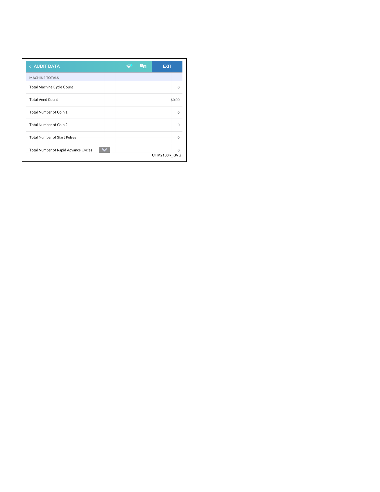
Audit Data Menu
Figure 43
The Audit Menu allows the user to read audit data via the touch
display rather than connecting to a PC.
The display will show the following audit parameters:
Audit Data Menu
• Machine Totals
• Total number of machine cycles
• Total vend count
• Total number of Coins#1
• Total number of Coins#2
• Total number of start pulses
• Total number of rapid advance cycles
• Total number of run hours
• Resettable Counters
• Other Metrics
• Individual Cycle Counts
1. To access, touch and hold the center of the menu header on
the display with the service door open and, for coin models,
the coin vault closed. The control enters the System Menu.
2. Touch AUDIT DATA from the display to enter the Audit
Menu.
3. Swipe to view the information.
4. When finished viewing or running diagnostics, touch AUDIT
DATA to return to the System Menu or EXIT to exit the Sys-
tem Menu.
©
Copyright, Alliance Laundry Systems LLC -
DO NOT COPY or TRANSMIT
84 Part No. F8669401ENR4
Page 85
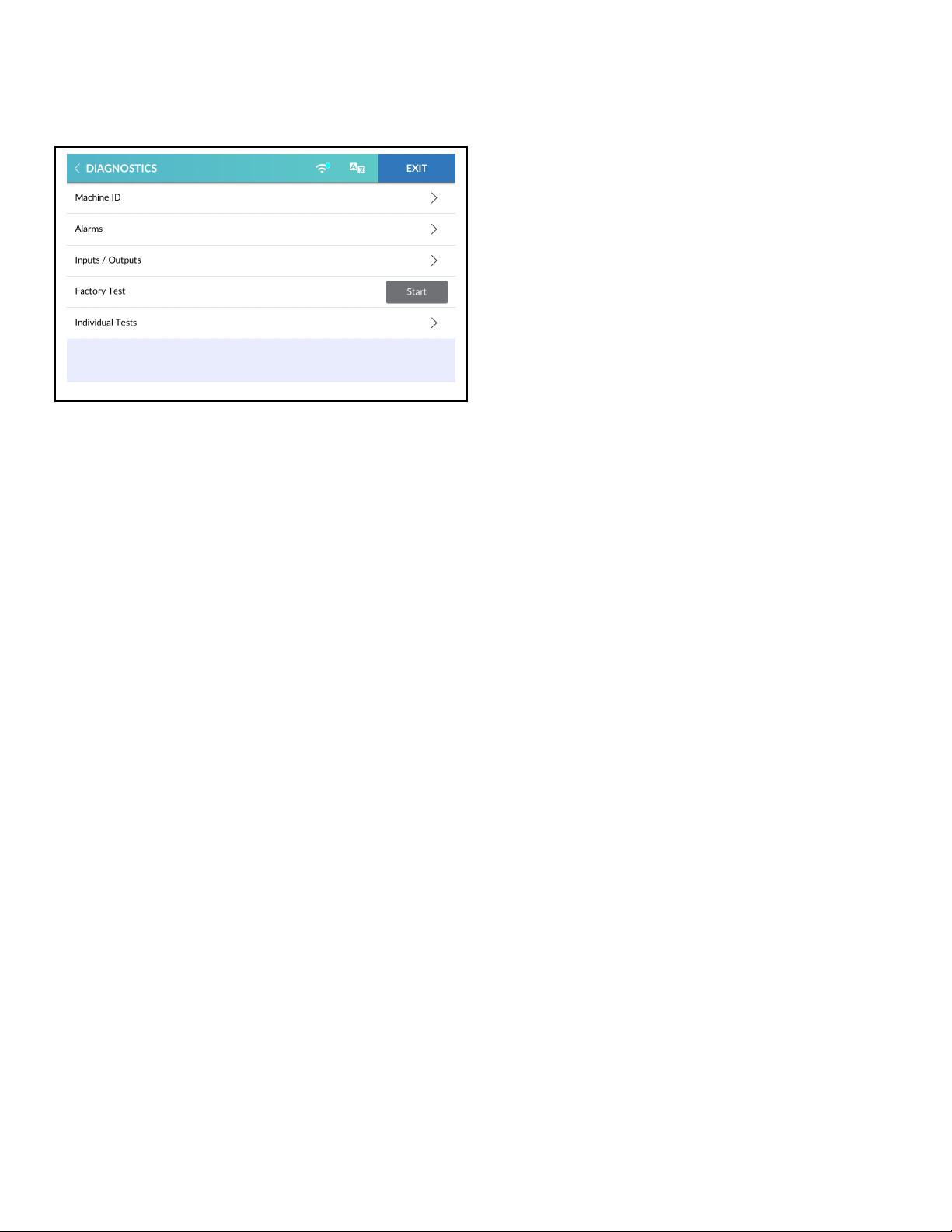
Diagnostics Menu
CHM2109R_SVG
Figure 44
The Diagnostics Menu includes MACHINE ID ( Machine ID Menu), ALARMS ( Alarms Menu), INPUTS/OUTPUTS ( Inputs/ Outputs Menu), FACTORY TEST ( Factory Test Menu) and IN-
DIVIDUAL TESTS ( Individual Tests Menu).
1. To access, touch and hold the center of the menu header on
the display with the service door open and, for coin models,
the coin vault closed. The control enters the System Menu.
2. Touch DIAGNOSTICS from the display to enter the Diagnostics Menu.
3. When finished viewing or running diagnostics, touch DIAGNOSTICS to return to the System Menu or EXIT to exit the
System Menu.
Diagnostics Menu
Machine ID Menu
The Machine ID Menu displays the following information.
• Model
• Serial Number
• Install Date
• Machine Type
• Control Serial Number
• Network Node
• Water Level Parameters
• Front-end Control Software Version
• Display Software Version
• Auxiliary Board Software Version
• I/O Board Software Version
• Drive Board Software Version
• Drive Type
• Drive Parameters
1. To access, touch MACHINE ID from the Diagnostics Menu.
2. Swipe to scroll through the Machine ID Menu.
3. When finished viewing machine information, touch MACHINE ID to return to the Diagnostics Menu or EXIT to exit
the System Menu.
©
Copyright, Alliance Laundry Systems LLC -
DO NOT COPY or TRANSMIT
85 Part No. F8669401ENR4
Page 86
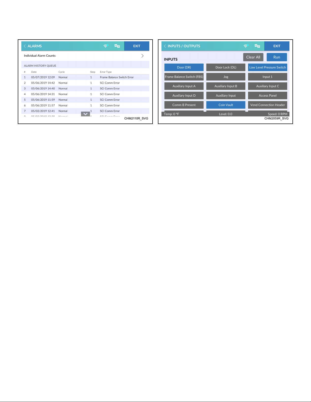
Diagnostics Menu
Alarms Menu
Figure 46
The Alarms Menu allows the owner to view total alarm occurrences, access the Individual Alarm Counts sub-menu, and view
the alarm history queue which includes the cycle, step, error type,
time and date details for the last 25 alarms.
1. To access, touch ALARMS from the Diagnostics Menu.
2. Swipe to scroll through the Alarms Menu.
3. When finished viewing or running diagnostics, touch
ALARMS to return to the Diagnostics Menu or EXIT to exit
the System Menu.
Inputs/Outputs Menu
Figure 47
The Inputs/Outputs Menu gives a user the ability to manipulate
machine outputs for component testing and monitor the current
state of all control inputs.
Selected outputs appear in a white field box. Actived inputs and
outputs appear in a dark blue filled box.
1. To access, touch INPUTS/OUTPUTS from the Diagnostics
Menu.
2. Touch desired outputs to include in the test.
NOTE: Touch CLEAR ALL to deselect all outputs.
3. Touch RUN to begin the outputs test. The test results show in
the footer of the display.
4. Touch CANCEL to end the test.
5. When finished viewing or running diagnostics, touch INPUTS/OUTPUTS to return to the System Menu or EXIT to
exit the System Menu.
©
Copyright, Alliance Laundry Systems LLC -
DO NOT COPY or TRANSMIT
86 Part No. F8669401ENR4
Page 87
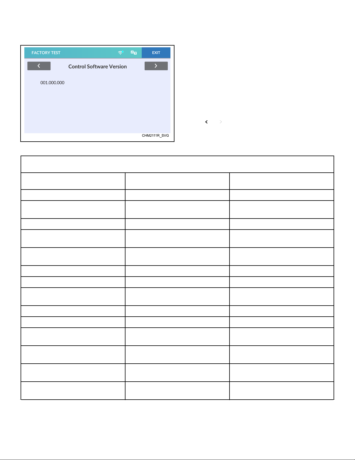
Diagnostics Menu
Factory Test Menu
If enabled in programming, the Factory Test Menu allows the
user to run a diagnostic test cycle.
At the start of the factory test cycle, the control enters Factory
Test Mode. The command message at the bottom of the Factory
Test Menu display will show the remaining step time or prompt
the user for input throughout the test cycle. Refer to Table 6 for
test sequence.
1. To access, touch FACTORY TEST from the Diagnostics
Menu.
2. Touch START to begin the factory test cycle.
3. Touch EXIT to terminate the factory test cycle.
4. Touch and to navigate between factory test steps.
5. The display returns to System Menu once the last test step is
complete.
Figure 48
Factory Tests
Test Name Display Description
Machine Type Washer Extractor Washer-extractor.
Control Software Version XXX.XX.XXX XXX is the control software version num-
ber.
Display Software Version XXX.XX.XXX XXX is the display cargo version number.
I/O Board Software Version XXX XXX is the control software version num-
ber.
Auxiliary Board Software Version Auxiliary Board Software Version: XXX XXX is the auxiliary board software ver-
sion number.
Control Level 1 Speed Queen Quantum Touch
Capacity CXXX XXX is the capacity in pounds.
Drain Configuration "Gravity Drain" or "Pump Drain" Displays which drain configuration is
present.
Door Switch Test "Open" or " Closed" Displays the state of the door switch.
Door Lock Test "Locked" or " Unlocked" The door will lock.
Touch Screen Test Touch START to begin The display instructs the operator to touch
various display locations.
Display Test This test will display a sequence of pat-
terns.
Touch display to advance through display
test patterns.
Frame Balance Switch Test "Open" or " Closed" Displays the state of the frame balance
switch.
Service Door Switch Test "Open" or " Closed" Displays the state of the frame balance
switch.
Table 6 continues...
©
Copyright, Alliance Laundry Systems LLC -
DO NOT COPY or TRANSMIT
87 Part No. F8669401ENR4
Page 88
Diagnostics Menu
Factory Tests
Test Name Display Description
Coin Vault Switch Test "Open" or " Closed" Displays the state of the service door
switch.
Coin Drop Test Coin 1: XXX
Coin 2: YYY
X and Y are the number of pulses received
for drop #1 and drop #2.
Drive Software Version XXX XXX is the drive software version number.
Drive Parameter Version XXX XXX is the drive parameter version num-
ber.
Drive Type "1HP 120V", "2HP 240V", "2HP 480V",
Displays the drive type of the machine.
"3HP 240V", "5HP 240V", "5HP 480V",
"7HP 240V", "7HP 480V", "10HP 280V",
"10HP 480V"
Hot Tub Fill Water Level: XXX Equipped models only. XXX is the level.
The control turns on the valve. The ma-
chine fills to the low water level or over-
flow water level (if the control has already
verified the high water level).
Cold Tub Fill Water Level: XXX Equipped models only. XXX is the level.
The control turns on the valve. The ma-
chine fills to the low water level or over-
flow water level (if the control has already
verified the high water level).
Hot Water Fill Water Level: XXX Equipped models only. XXX is the level.
The control turns on the valve. The ma-
chine fills to the low water level or over-
flow water level (if the control has already
verified the high water level).
Cold Water Fill Water Level: XXX Equipped models only. XXX is the level.
The control turns on the valve. The ma-
chine fills to the low water level or over-
flow water level (if the control has already
verified the high water level).
Compartment 1 Fill Water Level: XXX Equipped models only. Water enters the
machine through the supply dispenser's
compartment 1. The display indicates the
water level, which is represented with an
XXX.
Compartment 2 Fill Water Level: XXX Equipped models only. Water enters the
machine through the supply dispenser's
compartment 2. The display indicates the
water level, which is represented with an
XXX.
Table 6 continues...
©
Copyright, Alliance Laundry Systems LLC -
DO NOT COPY or TRANSMIT
88 Part No. F8669401ENR4
Page 89
Diagnostics Menu
Factory Tests
Test Name Display Description
Compartment 3 Fill Water Level: XXX Equipped models only. Water enters the
machine through the supply dispenser's
compartment 3. The display indicates the
water level, which is represented with an
XXX.
Compartment 4 Fill Water Level: XXX Equipped models only. Water enters the
machine through the supply dispenser's
compartment 4. The display indicates the
water level, which is represented with an
XXX.
Cold Hard Fill Water Level: XXX Equipped models only. XXX is the level.
The control turns on the valve. The ma-
chine fills to the low water level or over-
flow water level (if the control has already
verified the high water level).
Auxiliary Fill Water Level: XXX Equipped models only. XXX is the level.
The control turns on the valve. The ma-
chine fills to the low water level or over-
flow water level (if the control has already
verified the high water level).
Chemical Flush Water Level: XXX Equipped models only. XXX is the level.
The control turns on the valve. The ma-
chine fills to the low water level or over-
flow water level (if the control has already
verified the high water level).
All Fill to High Level Water Level: XXX Equipped models only. Water enters the
machine through all of the supply dispens-
er's compartments until the high water lev-
el is reached. The display indicates the wa-
ter level, which is represented with an
XXX.
Electric/Steam Heater Test "Electric Heat" or "Steam Heat"
Temperature: XXY
Heat models only. XX is the temperature
and Y is the units (Celsius or Fahrenheit).
Low Agitate RPM: XX XX is the current basket speed.
Regular Agitate RPM: XX XX is the current basket speed.
Drain/Pump RPM: XX XX is the current basket speed. The con-
trol turns on the Electric Pump or the
opens the Gravity Drain.
Purge RPM: XXX XXX is the current basket speed. The con-
trol opens all valves so compressed air can
be used to purge the valves of water.
©
Copyright, Alliance Laundry Systems LLC -
DO NOT COPY or TRANSMIT
Table 6 continues...
89 Part No. F8669401ENR4
Page 90
Diagnostics Menu
Factory Tests
Test Name Display Description
Balance RPM: XXX XXX is the current basket speed.
Very Low Spin RPM: XXX XXX is the current basket speed. The con-
trol will advance after 80 seconds.
Low Spin RPM: XXX XXX is the current basket speed. The con-
trol will advance after 80 seconds.
Medium Spin RPM: XXX XXX is the current basket speed. The con-
trol will advance after 80 seconds.
High Spin RPM: XXX XXX is the current basket speed. The con-
trol will advance after 80 seconds.
Very High Spin RPM: XXX XXX is the current basket speed. The con-
trol will advance after 80 seconds.
Ultra High Spin RPM: XXX XXX is the current basket speed. The con-
trol will advance after 80 seconds.
Coast Down "Do not power down the machine " Coast down is in process.
Table 6
©
Copyright, Alliance Laundry Systems LLC -
DO NOT COPY or TRANSMIT
90 Part No. F8669401ENR4
Page 91
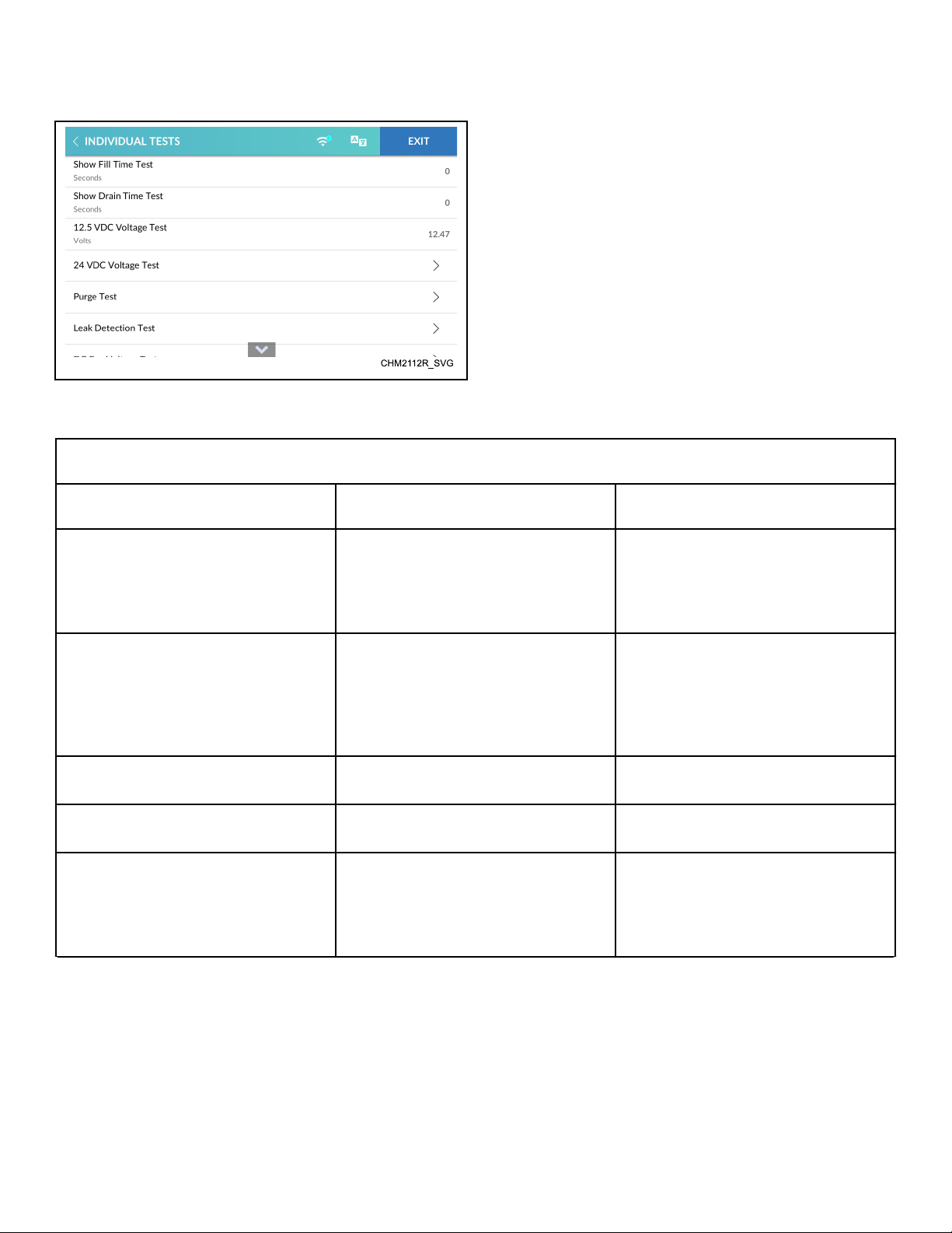
Diagnostics Menu
Individual Tests Menu
The Individual Tests Menu allows the user to preform individual
manual diagnostic tests on machine components. Refer to Table
7 .
1. To access, touch INDIVIDUAL TESTS from the Diagnostics
Menu.
2. Swipe to scroll through the list of individual tests.
3. Touch the desired individual test.
4. Touch START to begin each individual test.
NOTE: The time remaining in the test step displays
while the step is in process. The control indicates
the test results when the test step is complete.
5. Touch STOP to terminate the individual test.
6. Touch another test step name from the list to navigates between test steps.
Figure 49
7. When finished running the individual tests, touch INDIVIDUAL TESTS to return to the System Menu or EXIT to exit the
System Menu.
Individual Diagnostic Tests
Test Name Display Description
Show Fill Time Test XXXXXs XXXXX is the average Wash Fill time in
seconds. “s” is seconds. The average fill
time is calculated by taking the average of
the last ten (10) fill times from start of the
fill until the desired water level is reached.
Show Drain Time Test XXXXXs XXXXX is the average drain time in sec-
onds. “s” is seconds. The average drain
time is calculated by taking the average of
the last ten (10) drain times from start of
the drain until the empty water level is
reached.
12.5VDC Voltage Test XX.XXV XX.XX is the value of the 12.5VDC supply. “V” is volts.
24VDC Voltage Test XX.XXV XX.XX is the value of the 24VDC supply.
“V” is volts.
Purge Test "Ready" or "Running" The door locks and all water valves and
supply outputs turn on. The drain valves
open or the pump engages. If STOP is
touched, the test ends and the door unlocks
after there is no water in the system.
Table 7 continues...
©
Copyright, Alliance Laundry Systems LLC -
DO NOT COPY or TRANSMIT
91 Part No. F8669401ENR4
Page 92
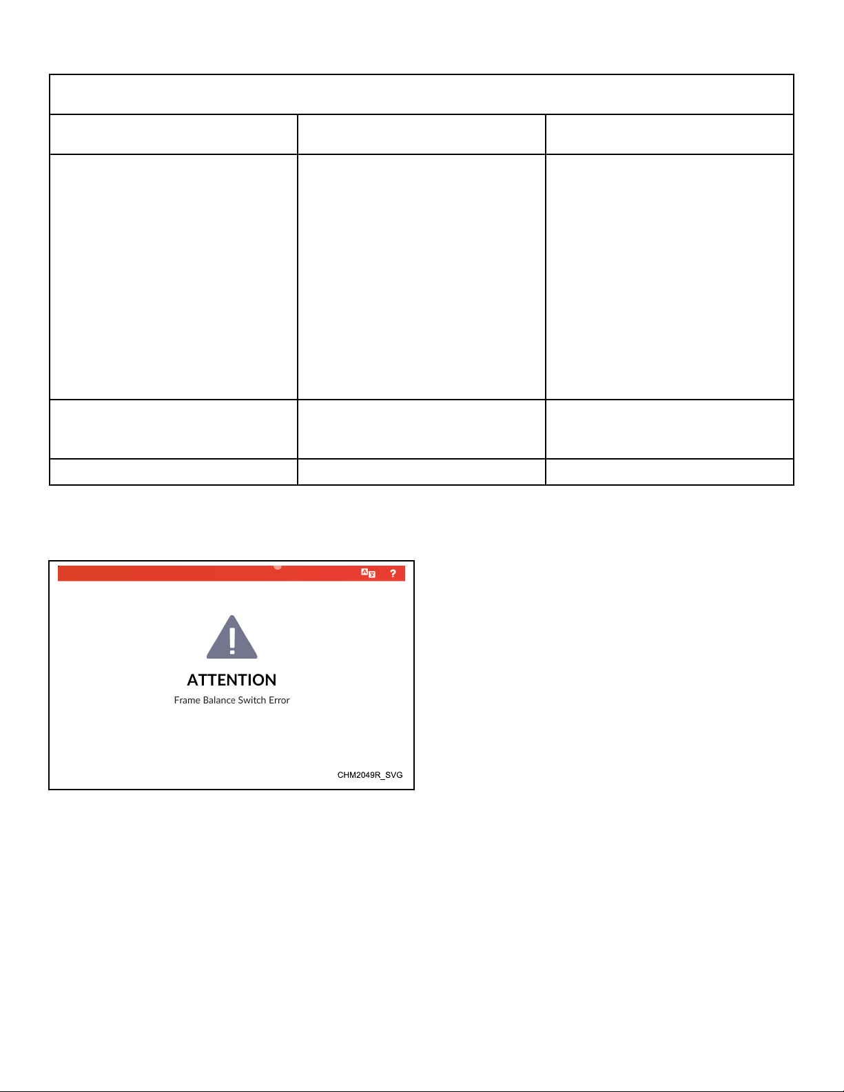
Diagnostics Menu
Individual Diagnostic Tests
Test Name Display Description
Leak Detection Test "Filling", "Checking", then "Pass", "Drain
Leak" , " Valve Leak"
The door locks. The drain valve closes or
the pump remains disengaged.
The Cold Water Valve Compartment 1
Valve and Compartment 2 valve turn on.
The Cold Water Valve turns off once the
fill reaches low water level. After a 10
second delay, the control records the current water level and continues to monitor
the water level for two minutes. The display will show "Pass", " Drain Leak" or
"Valve Leak".
The drain valve opens or the pump engages and the door unlocks.
DC Bus Voltage Test XXX XXX is the current DC Bus Voltage. The
door locks at the start of the test and unlocks an the end of the test.
AC Mains Voltage Test XXX XXX is the current AC Mains Voltage.
Table 7
Machine Errors
Auxilary Communication Error (Fatal)
Figure 50
The control displays and logs errors as they occur. When the control senses the error condition, the audit counter for that error increases by one (1). The control saves the time and date of the last
25 errors which have occurred.
Clear errors manually (if enabled in programming) by touching
CLEAR ERROR (when shown), send the clear fatal error command using a PC or cycle power to the machine.
Certain errors trigger a 15 second Machine Error Tone. Touch the
display to silence the tone.
This error occurs if a loss of communication occurs between the
auxiliary output board and the input/output board.
The control attempts to clear the error a three (3) times. The control attempts to unlock the door, then sets the error and displays
"Auxiliary Comm Error".
Break-In Alarm Error
If enabled in programming, the user has (30) seconds to enter the
bypass passcode after opening the Service Door and/or Coin
Vault. If thirty (30) seconds expire or an incorrect passcode is entered, the control triggers the a Break-In Alarm.
The control signals a network alarm, cause a machine alarm or
shut down the machine. The date and time of the break-in is recorded.
The owner can program an alarm to sound (if the passcode is not
correctly entered) upon Coin Vault Opening, Service Door Opening or both.The error is non-fatal will clear by itself after 15 seconds.
The owner can also program the machine to shut down (if the
passcode is not correctly entered) upon Coin Vault Opening,
Service Door Opening or both. The error is fatal and the control
will shut down the machine at the end of a cycle, if one is in
process.
©
Copyright, Alliance Laundry Systems LLC -
DO NOT COPY or TRANSMIT
92 Part No. F8669401ENR4
Page 93

Diagnostics Menu
The hour, date and error code of the event are saved in audit. The
error display takes priority over any other error that is already set.
To avoid the alarm during coin collections, the alarm must be
turned off or temporarily disabled
Board ID Error (Fatal)
This error occurs when an incorrect board is connected for the
machine type and configuration.
The control checks that the connected drive or output board is the
correct board. The control also checks that the correct drive and
auxiliary output board is connected. The control sets the Board
ID Error if the wrong drive motor or auxiliary board is connected
for the machine configuration. The display shows "Output Board
ID Error", "Drive Board ID Error " or "Auxiliary Board ID Error", according to the error.
Broken Belt Error (Fatal)
This error occurs if the control detects that the drive belt has fallen off or broken. This error is a fatal error and the control turns
off all outputs. The display shows "Broken Belt Error".
Brownout/Voltage Configuration Error
This error occurs if the control senses input voltage that does not
match the machine configuration. The display shows "Voltage
Configuration Error". To clear the error, correct the the input voltage or the voltage configuration parameter (refer to Settings
Menu), then cycle power to the machine power.
Coin Drop Error
If enabled in programming, a Coin Drop Error occurs if a coin input pulse is too short, if the input is too long or if the input is too
close to the previous input. The control displays "Coin Error" and
turn on the Machine Error Tone for five (5) seconds, after which
the error terminates. The coin error #1 or #2 audit counters will
be incremented. Any valid coins are accepted normally and will
terminate the error condition.
If the coin error penalty parameter is enabled and the coin error is
enabled in programming, when a coin error occurs all vend progress is lost and the control returns to the Approach Page.
Door Lock Error (Fatal)
This error occurs if the door unlocks durring a cycle. The control
terminates the cycle, turns off all outputs, sounds the Machine Error Tone and records the error in Audit Data Menu.
Door Lock Error (Non-Fatal)
This error occurs if the door fails to lock after an attempt. The
control displays "Door Lock Error". The output board attempts to
lock the door for an additional one (1) minute. The control continues to display "Door Lock Error" for an additional 10 seconds
after ceasing attempts to lock the door.
Door Open Error (Fatal)
This error occurs if the control senses the door open during a running cycle. The control terminates the cycle and displays "".
Door Unlock Error
This error occurs when the door fails to unlock. The error sets on
the first failed attempt to unlock the door. The control displays .
The output board attempts to unlock the door two (2) more times.
If the door still fails to unlock, the control prompts the user to restart the cycle. If the cycle is restarted, the error clears and the attempts will be restarted.
Drain Error (Fatal)
This error occurs when the machine failed to drain properly.
If enabled in programming, the Drain Error is set when the water
height is not below the empty level after attempting to drain for
the programmed time. The control turns off all outputs and displays .
If disabled, the control continues draining the machine with the
total remaining cycle time paused and no error display.
In the event of a fatal error, the drive will power down, allowing
the door to unlock.
Drive Communication Error (Fatal)
This error occurs when a loss of communication between the
drive board and I/O board is detected. The control unlocks the
door and displays "Drive Comm Error". If the error is set while
the basket is rotating at a dangerous speed, the control will coast
down the basket to a stop before unlocking the door.
©
Copyright, Alliance Laundry Systems LLC -
DO NOT COPY or TRANSMIT
Drive Board Errors
This error occurs if the control receives error code from the Drive
Board. The control turns off all outputs, sounds the Machine Error Tone for 15 seconds, and displays "Drive Error (XXX)"
where "XXX" is the specific error code (refer to Table 8 and Ta-
ble 9 ). When a Drive Error occurs, the specific error is counted
in Audit Data Menu. Fatal Drive Errors are added to the last 25
errors queue. The non-fatal errors are not.
93 Part No. F8669401ENR4
Page 94
Diagnostics Menu
ALS Drive Errors
"XX" Description
21 Over Voltage DC Bus
22 Over Motor Temperature
23 Fatal IPM Over Current Shunt
24 Fatal I2T Hardware Over Cur-
rent
25 IPM Over Temperature
29 Motor Not Connected Error
31 Overload Current Detection
32 Back EMF
33 Fatal Startup
34 Locked Rotor
51 Inrush Pin HW On/Off Fail
63 Fatal IPM Temperature Short
Error
64 Fatal IPM Temperature Open
Error
65 Inverter Hardware Acquisition
Failure
66 Voltage Bus Acquisition Fail-
ure
70 Unbalance Switch Error
Table 8
Powerflex Drive Errors
"XX" Description
2 Auxiliary Input
3 Power Loss
4 Under Voltage
5 Over Voltage
6 Motor Stalled
7 Motor Overload
8 Heatsink Over Temperature
9 Control Module Over Temper-
ature
12 HW Overcurrent (300%)
13 Ground Fault
15 Load Loss
21 Output Phase Loss
29 Analog Input Loss
33 Auto Restart Tries
38 Phase U to Ground Short
39 Phase V to Ground Short
40 Phase W to Ground Short
41 Phase UV Short
42 Phase UW Short
43 Phase VW Short
©
Copyright, Alliance Laundry Systems LLC -
DO NOT COPY or TRANSMIT
48 Parmeters Defaulted
59 Safety Open
63 Software Overcurrent
64 Drive Overload
70 Power Unit Fail
71 DSI Network Loss
72 Option Card Network Loss
73 Embedded Ethernet/IP Adapt-
er Network Loss
80 Auto Tune Fail
81 DSI Communication Loss
Table 9 continues...
94 Part No. F8669401ENR4
Page 95
Diagnostics Menu
Powerflex Drive Errors
"XX" Description
82 Option Card Communication
Loss
83 Embedded Ethernet/IP Adapt-
er Communication Loss
91 Encoder Loss
94 Function Loss
100 Parmeter Checksum Error
101 External Storage
105 Control Module Connect Error
106 Incompatible Control-Power
Module
107 Unrecognizable Control-Pow-
er Module
109 Mismatched Control-Power
Module
110 Keypad Membrane
111 Safety Hardware
114 Microprocessor Failure
122 I/O Board Fail
Fill Error (Fatal)
If enabled in programming, this error occurs if the machine fails
to fill to the desired water level within the programmed time after
starting the fill. In addition to the error being programmable, the
wait time before setting the error can be programmed.
When the error is set, the machine drains for 90 seconds, unlocks
the door, and turns off all outputs. The display shows " Fill Error".
If the error is disabled, the machine continues filling with the total remaining cycle time paused.
Frame Balance Switch Error (Fatal)
This error occurs if the frame balance switch become unsatisfied
while the control is running a cycle. The control stops the cycle,
turns off all outputs and displays "Frame Balance Switch Error".
Heater Error (Heat Models)
If the error is enabled in programming, this error occurs if the desired water temperature is not reached. If the heater is enabled in
programming and the water temperature has not reached the desired temperature within the programmed time, the control sets
the error. The control shuts off heater output and the cycle will
continue. At the end of the cycle, the control displays "Heater Error".
If the error is disabled, the control does not display "Heater Error" at the end of the cycle or log the error, but turns off the heater output and does not attempt to heat for the remainder of the cycle.
125 Flash Update Required
126 Non Recoverable Error
127 DSI Flash Update Required
Table 9
Drive/Output Board Not Ready Error (Fatal)
This error occurs when the Drive Board or Output Board is not
set up. This error indicates the control never received a status
from the Output Board indicating the Output Board is ready.
When the error is set, the control displays "Board Not Ready Error".
Drive/Output Board Shorted Error (Fatal)
This error occurs if the Output Board or drive enable relay fails to
change state. If the control is able to communicate to the Output
Board with the Drive/Output Board relay enable output programmed to 'disabled', this indicates that the Drive or Output Board is
powered when it should not be. If this is detected, the control terminates the cycle, sets the error and displays "Board Shorted Error".
©
Copyright, Alliance Laundry Systems LLC -
DO NOT COPY or TRANSMIT
95 Part No. F8669401ENR4
Page 96
Diagnostics Menu
IR Communications Error
This error occurs if there is a problem with communication between the control and an IR device. The control displays "IR
Comm Error (XXX)" where "XXX" indicates the error code value. Refer to Table 10 .
Error Code Description
01 Error detected when sending
data
02 Time-Out Error
03 Invalid Command Code
05 Invalid or Out of Range Data
09 CRC-16 Error
0A Framing Error
0C Time-Out Exceeding While
Getting Packet
0E Encryption Error
0F IR Disabled in Control Pro-
gramming
Machine ID Chip Error
This error occurs if the control detects either a communication error with the machine ID chip or a control configuration error. The
control displays "Machine ID Chip Error (XXX)". "XXX" indicates an error code value. Refer to Table 11 .
Error Code Description Type
05 Read Error Notification
06 Write Error Notification
31 Product byte 1 mis-
match
32 Product byte 2 mis-
match
33 Product byte 3 mis-
match
39 CRC error with un-
configured control
FF No ID chip con-
nected and no configuration in control
Power Up
Power Up
Power Up
Power Up
Power Up
Table 10
Leak Detection (Drain) Error
This error occurs if the water level lowers more than an acceptable amount. The error sets when a Water Leak Diagnostic Test is
run during a cycle and the water level lowers more than an acceptable amount during a drain cycle step. When the cycle is
complete, the display shows "Leak Detection (Drain) Error" .
Leak Detection (Fill) Error
This error occurs if the water level rises more than an acceptable
amount. The error sets when a Water Leak Diagnostic Test is run
during a cycle and the water level rises more than an acceptable
amount during a fill cycle step. When the cycle is complete, the
display shows " Leak Detection (Fill) Error".
Low Level Pressure Sensor Error (Heat Models) (Fatal)
Factory error detecting incorrect low level pressure sensor switch
status. This error will only trigger during a factory test cycle. The
error sets after the door lock step, before fill steps and when the
Low Level Pressure switch has been satisfied OR when the High
Water Level is verified and the control senses that the Low Level
Pressure Switch is unsatisfied. The control displays "Low Level
Pressure Switch Error".
Table 11
Notification errors occur when communication between the control and ID chip has failed. When the error is set, the hour, date
and error code of the event are saved in Audit Information.
Power Up errors occur when the control is not configured and
cannot get configuration data from the Machine ID chip. The error clears once the control is successfully configured.
Max Temperature Exceeded Error (Heat Models) (Fatal)
This error occurs if the maximum water temperature was exceeded. If the water temperature exceeds the maximum allowed temperature of 194°F [95°C] for 10 seconds, the control displays
"Max Temperature Exceeded Error".
©
Copyright, Alliance Laundry Systems LLC -
DO NOT COPY or TRANSMIT
96 Part No. F8669401ENR4
Page 97
Diagnostics Menu
Network Communications Error
This error occurs if communication fail between the control and
the ALS Wi-Fi board. When the error sets, the control displays
"Network Error". The error code is not shown, but it is recorded
in audit data. Refer to Table 12 .
Error Code Description
02 Time-Out Error
03 Invalid Command Code
05 Invalid or Out of Range Data
06 Invalid Data Code
09 CRC-16 Error
19 No Communication
Table 12
No Water Flow Error (Fatal)
If enabled in programming, this error occurs if the machine fails
to fill to the minimum water level on time. If the control does not
reach a water level of four (4) inches within the first programmed
time of starting the fill , the control displays "No Water Flow Error".
This error may mean the hose to the pressure sensor has a leak or
no water is flowing into the machine.
Open Thermistor Error (Heat Models)
If enabled in programming, this error occurs if the control senses
an unrealisticly low temperature. The error sets if the control detects a temperature less than or equal to 32°F [0°C] while trying
to regulate the fill temperature by cycling water valves or heating. The display shows "Open Thermistor Error" at the end of the
cycle.
If this error occurs while the control is regulating the fill temperature by cycling valves, the control will revert to non-regulated fill
temperature. If this error occurs while the machine is heating, the
control will turn off the heater output and not attempt to heat. The
cycle will complete normally.
Output Board Errors
This error occurs if the control receives error code from the Output Board. The control turns off all outputs, sounds the Machine
Error Tone for 15 seconds, and displays "Output Board Error
(XXX)" where "XXX" is the specific error code (refer to Table
13 ). When an Output Error occurs, the specific error is counted
in Audit Data Menu.
Output Board Errors
"XX" Description
1 Setup Error
2 Voltage Select
3 Under Voltage AC-Main Input
4 Over Voltage AC-Main Input
5 Power Fail Dangerous
6 Power Fail No Danger
7 Under Voltage DC Bus Error
Table 13
Overflow Error (Fatal)
This error occurs if the machine fills beyond the overflow limit.
If the error continues after five (5) minutes with the door locked
or after one (1) minute with the door open or unable to lock, the
error will be set. The control displays "Overflow Error" and will
continuously sound the Machine Error Tone at the highest volume one second on, one second off. The machine continues to
pump or the gravity drain remains open.
Payment System Communications Error
These errors may occur during communication with the Serial
Payment System. The display shows " No Payment System initialization performed", "Loss of communication" or "No initialization and no communication ", according to the error. Once communications are restored, the control returns to the previous state.
The hour, date and error code of the event are saved.
If the machine is in life test, the error is fatal.
©
Copyright, Alliance Laundry Systems LLC -
DO NOT COPY or TRANSMIT
Pressure Sensor Error (Fatal)
This error occurs if the control fails to detect a valid water level.
The error sets if the control does not detect a valid water level for
30 seconds or if the Max (Overflow) Fill Level in the control is
set to zero (0) while running a cycle or a factory test. The control
displays "Pressure Sensor Error", Machine Error Mode the machine drains for 30 seconds, unlocks the door, then turns off all
outputs.
97 Part No. F8669401ENR4
Page 98
Diagnostics Menu
SCI Communication Error (Fatal)
This error occurs if communication fails between the control and
the drive or output board. SCI Communications Errors can also
be caused by drive or output board detecting a System Integrity
Error. The control displays "SCI Comm Error".
Shorted Thermistor Sensor Error (Heat Models)
If enabled in programming, this error occurs if the control senses
an unrealisticly high temperature. The error sets if the control detects a temperature greater than 212°F [100°C] while trying to
regulate the fill temperature by cycling water valves or heating.
The display shows "Shorted Thermistor Error" at the end of the
cycle.
If this error occurs while the control is regulating the fill temperature by cycling valves, the control will revert to non-regulated fill
temperature. If this error occurs while the machine is heating, the
control will turn off the heater output and not attempt to heat. The
cycle will complete normally.
If the machine is in life test, the error is fatal.
Slow Drain Detection Error
If enabled in programming, this error occurs when the control detects poor drain conditions. Poor drain conditions will cause a
longer than normal time for the water level to drop. There may be
several causes:
• a drain valve/pump malfunction
• a foreign object jammed in the drain valve/pump
• a poor drain connection between the machine drain and the
building sewer system.
• An over-suds condition may also affect the drain and lead to a
slow drain condition.
Suds Lock Error
If enabled in programming, this error occurs if the control detects
suds in the machine. The control checks for suds when in a spin
cycle step. If the control detects suds in the machine based on the
conditions noted in the Suds Removal Routine after preforming
the maximum number of programmed Suds Removal Routines,
the error is set.
After setting the error, the control limits the basket spin to a distribution speed for the rest of the cycle. When the cycle is complete, the control displays "Suds Lock Error".
System Integrity Error
This error occurs if a SCI Communication Error (Fatal) happens
on the drive or output board. When the error sets, drive or output
board stops communication with the control. The output board
displays the error by flashing LEDs on and off. The machine
must be powered down to clear the error.
Error Description Number of LED Flashes
CPU Error 1
SFR Error 2
ROM Error 3
RAM Error 4
Stack Error 5
RAM Buffer and Empty Error 6
Software Watchdog Error 7
Slow Monitoring Error 8
During a drain cycle step, the control tracks the time required for
the water to drop from the Global Water Level value (1) to below
the empty level. If the control senses a drain time greater than the
amount specified, the error sets and the display shows "Slow
Drain Error" .
The default slow drain time is 105 seconds for a pump and 18
seconds for a gravity drain. This value can be adjusted by programming the Slow Drain Adjust Value, extending the slow drain
time for less than ideal drain plumbing situations.
Slow to Heat Error (Heat Models)
If enabled, this error occurs if the water temperature has not risen
for a programmed period of time. The time it takes for this error
to set from the start of heating is defined in programming. If the
time is programmed to zero (0) then the error is disabled. The
control displays "Slow To Heat Error" if the water temperature
does not rise by from the start of heating within the programmed
time.
If the machine is in life test, the error is fatal.
©
Copyright, Alliance Laundry Systems LLC -
DO NOT COPY or TRANSMIT
Too Hot to Drain Error
If enabled in programming, this error occurs if the water temperature is too high to safely drain the machine. The error sets when
the drive or output board indicates the water temperature is too
hot to safely drain while the machine is in a drain or extract step.
The display shows "Too Hot To Drain" when the cycle has complete.
This error could indicate a problem with the heater or that the
programmed agitation time is too short to effectively cool down
the water before trying to spin and drain.
Unbalance Limit Error
This error occurs if the extract speed is not reached because the
control detects an unbalanced load. The error sets when the maximum number of balance tries is reached and the balance result
does not allow for extract at the programmed speed. If enabled in
programming, the display shows "Unbalance Limit Error" when
the cycle is complete.
98 Part No. F8669401ENR4
Page 99
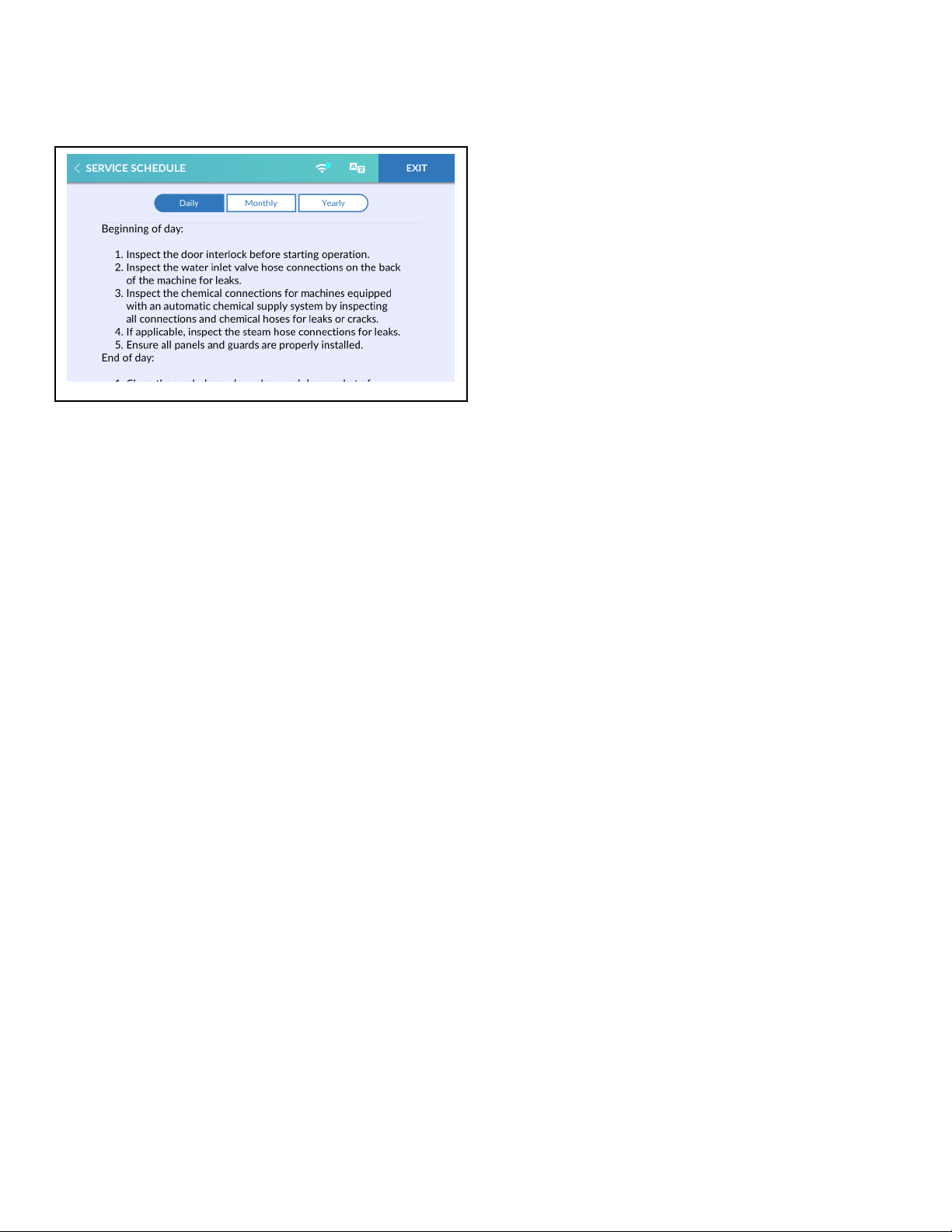
Service Schedule Menu
CHM2113R_SVG
Figure 51
The Service Schedule Menu allows the user to view instructions
for daily, monthly, and yearly machine maintenance.
1. To access, touch and hold the center of the menu header on
the display with the service door open and, for coin models,
the coin vault closed. The control enters the System Menu.
2. Touch SERVICE SCHEDULE from the display to enter the
Service Schedule Menu.
3. Touch Daily, Monthly or Yearly to view maintenance instructions.
4. Swipe to scroll through the service instructions.
5. When finished viewing instructions, touch SERVICE
SCHEDULE to return to the System Menu or EXIT to exit the
System Menu.
Service Schedule Menu
©
Copyright, Alliance Laundry Systems LLC -
DO NOT COPY or TRANSMIT
99 Part No. F8669401ENR4
Page 100
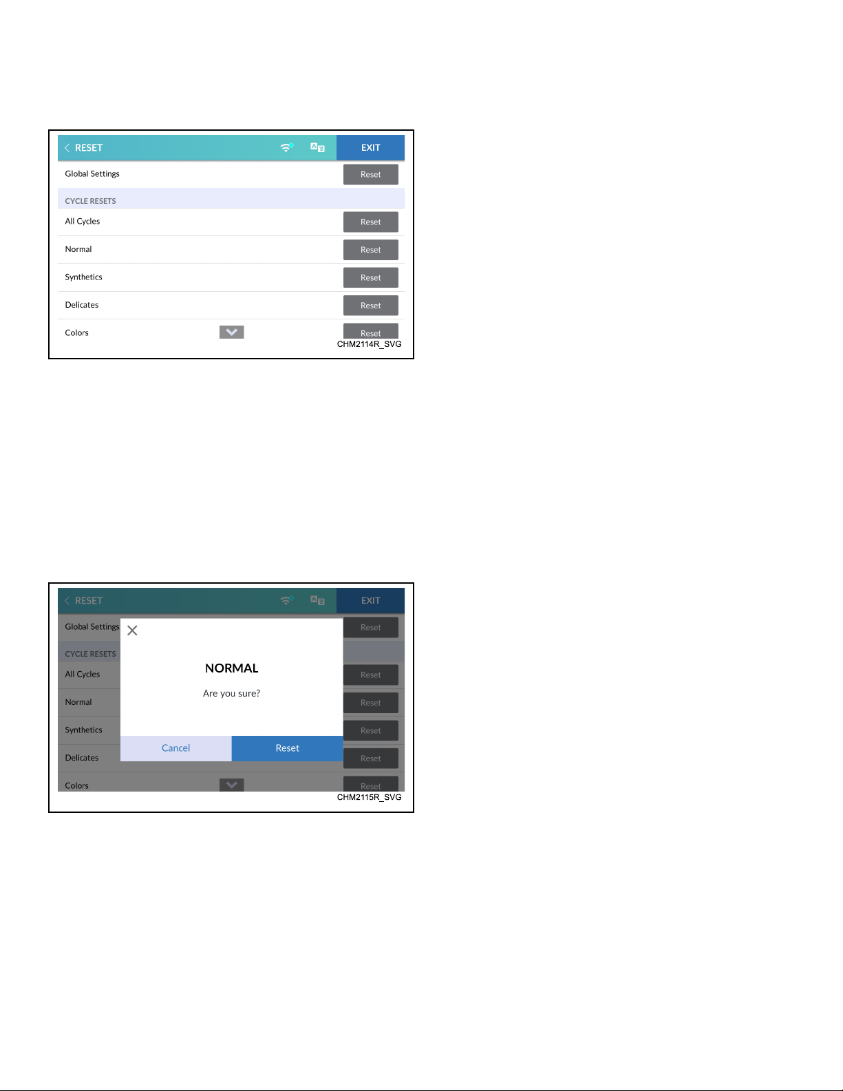
Reset Menu
Figure 52
If enabled (refer to System Menu), the Reset Menu allows the
user to reset the control's global and cycle programming data to
the factory default setting.
1. To access, touch and hold the center of the menu header on
the display with the service door open and, for coin models,
the coin vault closed. The control enters the System Menu.
2. Touch RESET from the display to enter the Reset Menu.
3. Swipe to scroll through the list of reset options.
4. Touch RESET next to the item to be reset. The display shows
the Reset Confirmation Menu. Refer to Figure 53 .
Reset Menu
Figure 53
5. Touch RESET to reset the list item to the factory default setting or touch CANCEL to return to the Reset Menu.
6. When finished making changes, touch EXIT to return to the
System Menu.
©
Copyright, Alliance Laundry Systems LLC -
DO NOT COPY or TRANSMIT
100 Part No. F8669401ENR4
 Loading...