


Washer-Extractors
Pocket Hardmount Variable-Speed
PS40 Control
Refer to Page 9 for Model Identification
Para bajar una copia de estas instrucciones en español, visite www.comlaundry.com
Keep These Instructions for Future Reference.
(If this machine changes ownership, this manual must accompany machine.)
PHM1397C
PHM1397C
|
|
|
www.comlaundry.com |
Part No. F8112101R2 |
|
|
|
||
|
|
|
September 2009 |
Installation
|
Safety Information.............................................................................. |
3 |
Table of |
Explanation of Safety Messages........................................................... |
3 |
Contents |
Safety Decals ........................................................................................ |
5 |
|
Important Safety Instructions ............................................................... |
3 |
|
Operator Safety..................................................................................... |
6 |
|
Safe Operating Environment ................................................................ |
6 |
|
Environmental Conditions ............................................................... |
6 |
|
Machine Location ............................................................................ |
7 |
|
Input and Output Services................................................................ |
7 |
|
DirectDrive ...................................................................................... |
8 |
|
Model Identification ............................................................................. |
9 |
|
Introduction......................................................................................... |
10 |
|
Delivery Inspection............................................................................... |
10 |
|
Nameplate Location.............................................................................. |
10 |
|
Replacement Parts ................................................................................ |
10 |
|
Customer Service.................................................................................. |
10 |
|
Specifications and Dimensions........................................................... |
11 |
|
High Speed Models............................................................................... |
11 |
|
Medium Speed Models ......................................................................... |
13 |
|
Machine Dimensions ............................................................................ |
15 |
|
40 Pound Models ............................................................................ |
16 |
|
60 Pound Models ............................................................................ |
17 |
|
80 Pound Models ............................................................................. |
18 |
|
100 Pound Models ........................................................................... |
19 |
|
125 Pound Models ........................................................................... |
20 |
|
140 Pound Models ........................................................................... |
21 |
|
175 Pound Models ........................................................................... |
22 |
|
Front and Rear Features........................................................................ |
23 |
|
Floor Load Data.................................................................................... |
24 |
|
Installation Instructions ........................................................................ |
26 |
|
Surface ............................................................................................. |
26 |
|
Anchors ............................................................................................ |
26 |
|
Mounting.......................................................................................... |
26 |
|
Mounting Bolt Installation Requirements ............................................ |
26 |
|
Location ........................................................................................... |
26 |
|
Clearances ........................................................................................ |
27 |
|
Installing Anchors............................................................................ |
29 |
|
Grouting and Setting Machine ......................................................... |
29 |
|
Mounting Bolt Hole Locations ............................................................. |
29 |
|
40 Pound Models ............................................................................ |
29 |
|
60, 80 and 100 Pound Models.......................................................... |
32 |
|
125, 140 and 175 Pound Models...................................................... |
34 |
|
Water Connection ................................................................................. |
36 |
|
Drain Connection Requirements........................................................... |
37 |
|
Electrical Installation Requirements..................................................... |
38 |
|
Circuit Breakers ............................................................................... |
39 |
|
Grounding ........................................................................................ |
39 |
|
Wire Size.......................................................................................... |
39 |
© Copyright 2009, Alliance Laundry Systems LLC
All rights reserved. No part of the contents of this book may be reproduced or transmitted in any form or by any means without the expressed written consent of the publisher.
F8112101 |
© Copyright, Alliance Laundry Systems LLC – DO NOT COPY or TRANSMIT |
1 |
Making Connections to Machine ..................................................... |
41 |
Adjusting Control Transformer Taps............................................... |
41 |
Provisions for 50 Hz Installations.................................................... |
41 |
Steam Requirements (Steam Heat Option Only).................................. |
42 |
Chemical Injection Supply System....................................................... |
43 |
Chemical Service Connections ........................................................ |
43 |
Connection of Chemical Supply Hoses ........................................... |
43 |
Connection of Chemical Pump Signals ........................................... |
44 |
First Start-Up...................................................................................... |
45 |
2 |
© Copyright, Alliance Laundry Systems LLC – DO NOT COPY or TRANSMIT |
F8112101 |

Safety Information
Explanation of Safety Messages
Precautionary statements (“DANGER,” “WARNING,” and “CAUTION”), followed by specific instructions, are found in this manual and on machine decals. These precautions are intended for the personal safety of the operator, user, servicer, and those maintaining the machine.
DANGER
DANGER indicates the presence of a hazard that will cause severe personal injury, death, or substantial property damage if the danger is ignored.
WARNING
WARNING indicates the presence of a hazard that can cause severe personal injury, death, or substantial property damage if the warning is ignored.
CAUTION
CAUTION indicates the presence of a hazard that will or can cause minor personal injury or property damage if the caution is ignored.
Additional precautionary statements (“IMPORTANT” and “NOTE”) are followed by specific instructions.
IMPORTANT: The word “IMPORTANT” is used to inform the reader of specific procedures where minor machine damage will occur if the procedure is not followed.
NOTE: The word “NOTE” is used to communicate installation, operation, maintenance or servicing information that is important but not hazard related.
Important Safety Instructions
WARNING
To reduce the risk of fire, electric shock, serious injury or death to persons when using your washer, follow these basic precautions:
W023
1.Read all instructions before using the washer.
2.Refer to the GROUNDING INSTRUCTIONS in the INSTALLATION manual for the proper grounding of the washer.
3.Do not wash textiles that have been previously cleaned in, washed in, soaked in, or spotted with gasoline, kerosene, waxes, cooking oils, drycleaning solvents, or other flammable or explosive substances as they give off vapors that could ignite or explode.
4.Do not add gasoline, dry-cleaning solvents, or other flammable or explosive substances to the wash water. These substances give off vapors that could ignite or explode.
5.Under certain conditions, hydrogen gas may be produced in a hot water system that has not been used for two weeks or more. HYDROGEN GAS IS EXPLOSIVE. If the hot water system has not been used for such a period, before using a washing machine or combination washer-dryer, turn on all hot water faucets and let the water flow from each for several minutes. This will release any accumulated hydrogen gas. The gas is flammable, do not smoke or use an open flame during this time.
6.Do not allow children to play on or in the washer. Close supervision of children is necessary when the washer is used near children. This is a safety rule for all appliances.
7.Before the washer is removed from service or discarded, remove the door to the washing compartment.
8.Do not reach into the washer if the wash drum is moving.
F8112101 |
© Published by permission of the copyright owner – DO NOT COPY or TRANSMIT |
3 |
Safety Information
9.Do not install or store the washer where it will be exposed to water and/or weather.
10.Do not tamper with the controls.
11.Do not repair or replace any part of the washer, or attempt any servicing unless specifically recommended in the user-maintenance instructions or in published user-repair instructions that the user understands and has the skills to carry out.
12.To reduce the risk of an electric shock or fire, DO NOT use an extension cord or an adapter to connect the washer to the electrical power source.
13.Use washer only for its intended purpose, washing textiles.
14.Never wash machine parts or automotive parts in the machine. This could result in serious damage to the basket.
15.ALWAYS disconnect the washer from electrical supply before attempting any service. Disconnect the power cord by grasping the plug, not the cord.
16.Install the washer according to the INSTALLATION INSTRUCTIONS. All connections for water, drain, electrical power and grounding must comply with local codes and be made by licensed personnel when required.
17.To reduce the risk of fire, textiles which have traces of any flammable substances such as vegetable oil, cooking oil, machine oil, flammable chemicals, thinner, etc., or anything containing wax or chemicals such as in mops and cleaning cloths, must not be put into the washer. These flammable substances may cause the fabric to catch on fire by itself.
18.Do not use fabric softeners or products to eliminate static unless recommended by the manufacturer of the fabric softener or product.
19.Keep washer in good condition. Bumping or dropping the washer can damage safety features. If this occurs, have washer checked by a qualified service person.
20.Be sure water connections have a shut-off valve and that fill hose connections are tight. CLOSE the shut-off valves at the end of each wash day.
21.Loading door MUST BE CLOSED any time the washer is to fill, tumble or spin. DO NOT bypass the loading door switch by permitting the washer to operate with the loading door open.
22.Always read and follow manufacturer’s instructions on packages of laundry and cleaning aids. Heed all warnings or precautions. To reduce the risk of poisoning or chemical burns, keep them out of the reach of children at all times (preferably in a locked cabinet).
23.Always follow the fabric care instructions supplied by the textile manufacturer.
24.Never operate the washer with any guards and/or panels removed.
25.DO NOT operate the washer with missing or broken parts.
26.DO NOT bypass any safety devices.
27.Failure to install, maintain, and/or operate this washer according to the manufacturer’s instructions may result in conditions which can produce bodily injury and/or property damage.
NOTE: The WARNINGS and IMPORTANT SAFETY INSTRUCTIONS appearing in this manual are not meant to cover all possible conditions and situations that may occur. Common sense, caution and care must be exercised when installing, maintaining, or operating the washer.
Any problems or conditions not understood should be reported to the dealer, distributor, service agent or the manufacturer.
4 |
© Published by permission of the copyright owner – DO NOT COPY or TRANSMIT |
F8112101 |
WARNING
This machine must be installed, adjusted, and serviced by qualified electrical maintenance personnel familiar with the construction and operation of this type of machinery. They must also be familiar with the potential hazards involved. Failure to observe this warning may result in personal injury and/or equipment damage, and may void the warranty.
SW004
IMPORTANT: Ensure that the recommended clearances for inspection and maintenance are provided. Never allow the inspection and maintenance space to be blocked.
CAUTION
Install the machine on a level floor of sufficient strength. Failure to do so may result in conditions which can produce serious injury, death and/or property damage.
W703
Safety Information
CAUTION
Be careful around the open door, particularly when loading from a level below the door. Impact with door edges can cause personal injury.
SW025
WARNING
Never touch internal or external steam pipes, connections, or components. These surfaces can be extremely hot and will cause severe burns. The steam must be turned off and the pipe, connections, and components allowed to cool before the pipe can be touched.
SW014
Safety Decals
Safety decals appear at crucial locations on the machine. Failure to maintain legible safety decals could result in injury to the operator or service technician.
To provide personal safety and keep the machine in proper working order, follow all maintenance and safety procedures presented in this manual. If questions regarding safety arise, contact the manufacturer immediately.
Use manufacturer-authorized spare parts to avoid safety hazards.
F8112101 |
© Published by permission of the copyright owner – DO NOT COPY or TRANSMIT |
5 |

Safety Information
Operator Safety
WARNING
NEVER insert hands or objects into basket until it has completely stopped. Doing so could result in serious injury.
SW012
To ensure the safety of machine operators, the following maintenance checks must be performed daily:
1.Prior to operating machine, verify that all warning signs are present and legible. Missing or illegible signs must be replaced immediately. Make certain that spares are available.
2.Check door interlock before starting operation of machine:
a.Attempt to start machine with door open. Machine should not start with door open.
b.Close door without locking it and attempt to start machine. Machine should not start with door unlocked.
c.Close and lock door and start a cycle. Attempt to open door while cycle is in progress. Door should not open.
If door lock and interlock are not functioning properly, call a service technician.
3.Do not attempt to operate machine if any of the following conditions are present:
a.Door does not remain securely locked during entire cycle.
b.Excessively high water level is evident.
c.Machine is not connected to a properly grounded circuit.
Do not bypass any safety devices in machine.
WARNING
Never operate the machine with a bypassed or disconnected balance system. Operating the machine with severe out-of-balance loads could result in personal injury and serious equipment damage.
SW039
Safe Operating Environment
Safe operation requires an appropriate operating environment for both the operator and the machine. If questions regarding safety arise, contact the manufacturer immediately.
Environmental Conditions
•Ambient Temperature. Water in machine will freeze at temperatures of 32°F (0°C) or below.
•Temperatures above 120°F (50°C) will result in more frequent motor overheating and, in some cases, malfunction or premature damage to solid state devices that are used in some models. Special cooling devices may be necessary.
•Water pressure switches are affected by increases and decreases in temperature. Every 25°F (10°C) change in temperature will have a 1% effect on the water level.
•Humidity. Relative humidity above 90% may cause machine’s electronics or motors to malfunction or may trip ground fault interrupter. Corrosion problems may occur on some metal components in machine.
•If relative humidity is below 30%, belts and rubber hoses may eventually develop dry rot. This condition can result in hose leaks, which may cause safety hazards external to machine in conjunction with adjacent electrical equipment.
•Ventilation. The need for make-up air openings for such laundry room accessories as dryers, ironers, water heaters, etc., must be evaluated periodically. Louvers, screens or other separating devices may reduce available air opening significantly.
•Radio Frequency Emissions. A filter is available for machines in installations where floor space is shared with equipment sensitive to radio frequency emissions.
•Elevation. If machine is to be operated at elevations of over 3280 feet (1000 m) above sea level, pay special attention to water levels and electronic settings (particularly temperature) or desired results may not be achieved.
•Chemicals. Keep stainless steel surfaces free of chemical residues.
6 |
© Published by permission of the copyright owner – DO NOT COPY or TRANSMIT |
F8112101 |
DANGER
Do not place volatile or flammable fluids in any machine. Do not clean the machine with volatile or flammable fluids such as acetone, lacquer thinners, enamel reducers, carbon tetrachloride, gasoline, benzene, naptha, etc. Doing so could result in serious personal injury and/or damage to the machine.
SW002
•Water Damage. Do not spray machine with water. Short circuiting and serious damage may result. Repair immediately all seepage due to worn or damaged gaskets, etc.
Machine Location
•Foundation. The concrete floor must be of sufficient strength and thickness to handle floor loads generated by high extract speeds of machine.
•Service/Maintenance Space. Provide sufficient space to allow comfortable performance of service procedures and routine preventive maintenance.
Consult installation instructions for specific details.
CAUTION
Replace all panels that are removed to perform service and maintenance procedures. Do not operate the machine with missing guards or with broken or missing parts. Do not bypass any safety devices.
SW019
Safety Information
Input and Output Services
•Water Pressure. Best performance will be realized if water is provided at a pressure of 30 – 85 psi (2 – 5.7 bar). Although machine will function properly at lower pressure, increased fill times will occur. Water pressure higher than 100 psi (6.7 bar) may result in damage to machine plumbing. Component failure(s) and personal injury could result.
•Steam Heat (Optional) Pressure. Best performance will be realized if steam is provided at a pressure of 30 – 80 psi (2 – 5.4 bar). Steam pressure higher than 125 psi (8.5 bar) may result in damage to steam components and may cause personal injury.
•For machines equipped with optional steam heat, install piping in accordance with approved commercial steam practices. Failure to install supplied steam filter may void warranty.
•Drainage System. Provide drain lines or troughs large enough to accommodate total number of gallons that could be released if all machines on site drained at same time from highest attainable level. If troughs are used, they should be covered to support light foot traffic.
•Power. For personal safety and for proper operation, machine must be grounded in accordance with state and local codes. Ground connection must be to a proven earth ground, not to conduit or water pipes. Do not use fuses in place of circuit breaker. An easy-access cutoff switch should also be provided.
WARNING
Ensure that a ground wire from a proven earth ground is connected to the ground lug near the input power block on this machine. Without proper grounding, personal injury from electric shock could occur and machine malfunctions may be evident.
SW008
Always disconnect power and water supplies before a service technician performs any service procedure. Where applicable, steam and/or compressed air supplies should also be disconnected before service is performed.
F8112101 |
© Published by permission of the copyright owner – DO NOT COPY or TRANSMIT |
7 |
Safety Information
DirectDrive
Machines equipped with DirectDrive require special attention with regard to operating environment.
•An especially dusty or linty environment will require more frequent cleaning of AC inverter drive cooling fan filter and of AC inverter drive itself.
•Power line fluctuations from sources such as uninterruptible power supplies (UPS) can adversely affect machines equipped with AC inverter drive. Proper suppression devices should be utilized on incoming power to machine to avoid problems.
•A clean power supply free from voltage spikes and surges is absolutely essential for machines equipped with AC inverter drive. Inconsistencies (peaks and valleys) in power supply can cause AC inverter drive to generate nuisance errors.
If voltage is above 230 Volt for 200 Volt installation or 460 Volt for 400 Volt installation, ask power company to correct. As an alternative, a step-down transformer kit is available from distributor. If voltage is above 240 Volt for 200 Volt installation or 480 Volt for 400 Volt installations, a buckboost transformer is required.
•Sufficient space to perform service procedures and routine preventive maintenance is especially important for machines equipped with AC inverter drive.
8 |
© Published by permission of the copyright owner – DO NOT COPY or TRANSMIT |
F8112101 |
Safety Information
Model Identification
Information in this manual is applicable to these models:
|
|
|
Medium Speed |
|
|
High Speed |
|
|
CP040PMN |
IP040PMQ |
|
CP040PHN |
IP040PHQ |
|
40 |
CP040PMQ |
IP040PMX |
|
CP040PHQ |
IP040PHX |
|
CP040PMX |
IPH40M |
|
CP040PHX |
IPH40H |
|
Pound |
|
|||||
CPC40M |
IPH180 |
|
CPC40H |
JP040PHN |
||
|
|
|
||||
|
|
IP040PMN |
|
|
IP040PHN |
JP040PHQ |
|
|
CP060PMN |
IP060PMQ |
|
CP060PHN |
IP060PHQ |
|
|
CP060PMQ |
IP060PMX |
|
CP060PHN |
IP060PHX |
|
60 |
CP060PMX |
IPH60M |
|
CP060PHQ |
IPH60H |
|
CPC60M |
IPH270 |
|
CP060PHX |
JP060PHN |
|
Pound |
|
|||||
IP060PMN |
JP060PMQ |
|
CPC60H |
JP060PHN |
||
|
|
|
||||
|
|
|
|
|
IP060PHN |
JP060PHQ |
|
|
|
|
|
IP060PHN |
|
|
|
CP080PMN |
IP080PMN |
|
CP080PHN |
IP080PHQ |
|
80 |
CP080PMN |
IP080PMQ |
|
CP080PHQ |
IPH80H |
|
CP080PMQ |
IPH80M |
|
CPC80H |
JP080PHN |
|
Pound |
|
|||||
CPC80M |
IPH370 |
|
IP080PHN |
JP080PHQ |
||
|
|
|
||||
|
|
IP080PMN |
|
|
|
|
|
|
CP100PMN |
IP100PMN |
|
CP100PHN |
IP100PHQ |
|
100 |
CP100PMN |
IP100PMQ |
|
CP100PHQ |
IPH100H |
|
CP100PMQ |
IPH100M |
|
CPC100H |
JP100PHN |
|
Pound |
|
|||||
CPC100M |
IPH460 |
|
IP100PHN |
JP100PHQ |
||
|
|
|
||||
|
|
IP100PMN |
JP100PMQ |
|
|
|
|
|
|
|
|
CP125PHN |
IP125PHQ |
|
125 |
|
Not Applicable |
|
CP125PHQ |
IPH125H |
Pound |
|
|
CPC125H |
IPH570 |
||
|
|
|
||||
|
|
|
|
|
IP125PHN |
JP125PHN |
|
|
|
|
|
|
|
|
|
CP140PMN |
IP140PMQ |
|
CP140PHN |
IP140PHQ |
|
140 |
CP140PMQ |
IPH140M |
|
CP140PHQ |
IPH140H |
Pound |
CPC140M |
IPH640 |
|
CPC140H |
JP140PHN |
|
|
|
IP140PMN |
JP140PMQ |
|
IP140PHN |
JP140PHQ |
|
175 |
|
|
|
CP175PHN |
IPH175H |
|
|
Not Applicable |
|
CPC175H |
IPH790 |
|
Pound |
|
|
||||
|
|
|
IP175PHN |
JP175PHN |
||
|
|
|
|
|
||
|
|
|
|
|
|
|
|
|
|
|
|
||
|
|
|
Model Number Familiarization Guide |
|
||
|
|
|
Sample Model Number: IP060PMQ1001U01 |
|
||
I |
Model Number Prefix Brand |
|
|
|||
P |
Product Family; P=IPH |
|
|
|
|
|
060 |
Washer-Extractor Capacity (pounds dry weight of laundry) |
|
|
|||
P |
Type of Control; P=PS40 |
|
|
|||
M |
Spin Speed; M=Medium |
|
|
|
|
|
Q |
Electrical Voltage; Q=200-208/220-240 Volt/50 or 60 Hertz/3 Phase |
|
||||
1 |
Design Series |
|
|
|
|
|
0Auxiliary Heating; 0 = Prep for Steam
0Plumbing; 0 = 2-Valve Standard Thread
1Chemical Supply; 1 = Single Dry Chemical Compartment with 6 Liquid Chemical Supply Connections.
U |
Agency Approval; U = ETL/ETLC |
01 |
Options Identification |
F8112101 |
© Published by permission of the copyright owner – DO NOT COPY or TRANSMIT |
9 |
Introduction
This manual is designed as a guide for the installation of a washer-extractor equipped with DirectDrive.
NOTE: All information, illustrations and specifications contained in this manual are based on the latest product information available at the time of printing. We reserve the right to make changes at any time without notice.
Delivery Inspection
Upon delivery, visually inspect crate, protective cover and unit for any visible shipping damage. If the crate, protective cover or unit is damaged or signs of possible damage are evident, have the carrier note the condition on the shipping papers before the shipping receipt is signed or advise the carrier of the condition as soon as it is discovered.
Remove the crate and protective cover as soon after delivery as possible. If any damage is discovered upon removal of the crate and/or protective cover, advise the carrier and file a written claim immediately.
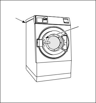
Nameplate Location
The nameplate is located inside the door and on the upper rear panel. Always provide the machine’s serial number and model number when ordering parts or when seeking technical assistance. Refer to Figure 1.
2
 1
1
Replacement Parts
If literature or replacement parts are required, contact the source from which the washer-extractor was purchased or contact Alliance Laundry Systems LLC at (920) 748-3950 for the name of the nearest authorized parts distributor. A parts manual may be ordered by returning the reply card provided with each washer-extractor.
Customer Service
For technical assistance, contact your local distributor or call:
(920) 748-3121 Ripon, Wisconsin
+32 56 41 20 54 Wevelgem, Belgium
A record of each washer-extractor is on file with the manufacturer. Always provide the machine’s serial number and model number when ordering parts or when seeking technical assistance. Refer to Figure 1.
PHM1397C
PHM1397N
1Inside the Door
2On Upper Rear Panel
Figure 1
10 |
© Published by permission of the copyright owner – DO NOT COPY or TRANSMIT |
F8112101 |
Specifications and Dimensions
High Speed Models |
|
|
|
. |
|
|
|
|
||
|
|
|
|
|
|
|
|
|
|
|
|
|
|
|
|
|
|
Models |
|
|
|
|
|
|
|
|
|
|
|
|
|
|
Specifications |
40H |
|
60H |
|
80H |
|
100H |
125H |
140H |
175H |
|
|
|
|
|
|
|
|
|
|
|
Overall Dimensions |
|
|
|
|
|
|
|
|
|
|
|
|
|
|
|
|
|
|
|
|
|
Overall Width, in. (mm) |
32 |
|
34.5 |
|
42.5 |
|
42.5 |
56.3 |
56.3 |
56.3 |
|
(813) |
|
(876) |
|
(1080) |
|
(1080) |
(1430) |
(1430) |
(1430) |
Overall Height, in. (mm) |
57 |
|
62.6 |
|
70 |
|
70 |
77.1 |
77.1 |
77.1 |
|
(1448) |
|
(1590) |
|
(1778) |
|
(1778) |
(1958) |
(1958) |
(1958) |
Overall Depth, in. (mm) |
45.6 |
|
47.8 |
|
51.4 |
|
56.4 |
56.1 |
59.1 |
64 |
|
(1158) |
|
(1213) |
|
(1306) |
|
(1433) |
(1425) |
(1502) |
(1626) |
Weight and Shipping Information |
|
|
|
|
|
|
|
|
||
|
|
|
|
|
|
|
|
|
|
|
Net Weight, lbs. (kg) |
1093 |
|
1367 |
|
1908 |
|
1979 |
2459 |
2725 |
2963 |
|
(496) |
|
(620) |
|
(866) |
|
(898) |
(1116) |
(1237) |
(1344) |
Domestic Shipping |
1150 |
|
1424 |
|
2001 |
|
2072 |
2557 |
2823 |
3064 |
Weight, lbs. (kg) |
(522) |
|
(646) |
|
(908) |
|
(940) |
(1160) |
(1281) |
(1390) |
Domestic Shipping |
63 |
|
76.9 |
|
110 |
|
122 |
160 |
167 |
179 |
Volume, ft.3 (m3) |
(1.78) |
|
(2.18) |
|
(3.11) |
|
(3.45) |
(4.53) |
(4.73) |
(5.16) |
Wash Cylinder Information |
|
|
|
|
|
|
|
|
||
|
|
|
|
|
|
|
|
|
|
|
Cylinder Diameter, |
27 |
|
31 |
|
37 |
|
37 |
43 |
43 |
43 |
in. (mm) |
(686) |
|
(787) |
|
(940) |
|
(940) |
(1092) |
(1092) |
(1092) |
Cylinder Depth, |
19 |
|
22 |
|
21 |
|
26 |
24 |
27 |
32 |
in. (mm) |
(483) |
|
(559) |
|
(533) |
|
(660) |
(610) |
(686) |
(813) |
|
|
|
|
|
|
|
|
|
|
|
Cylinder Volume, |
6.3 |
|
9.6 |
|
13.1 |
|
16.2 |
20.1 |
22.7 |
26.8 |
ft.3 (l) |
(178.3) |
|
(271.7) |
|
(370.7) |
|
(458.5) |
(569.2) |
(642.4) |
(759.9) |
Perforation Size, |
0.19 |
|
0.19 |
|
0.19 |
|
0.19 |
0.19 |
0.19 |
0.19 |
in. (mm) |
(4.83) |
|
(4.83) |
|
(4.83) |
|
(4.83) |
(4.83) |
(4.83) |
(4.83) |
Cylinder Capacity 1:10 |
39.3 |
|
60 |
|
81.6 |
|
101 |
125 |
141.7 |
175 |
Fill Ratio, lbs. (kg) |
(17.8) |
|
(27.2) |
|
(37) |
|
(45.9) |
(57) |
(64.3) |
(79.5) |
|
|
|
|
|
|
|
|
|
|
|
Door Opening Information |
|
|
|
|
|
|
|
|
||
|
|
|
|
|
|
|
|
|
|
|
Door Opening Size, |
15 |
|
17 |
|
20 |
|
20 |
24.5 |
24.5 |
24.5 |
in. (mm) |
(381) |
|
(432) |
|
(508) |
|
(508) |
(622) |
(622) |
(622) |
Height of Door Bottom |
25.5 |
|
28.8 |
|
29.6 |
|
30.1 |
34 |
34.3 |
34.8 |
Above Floor, in. (mm) |
(648) |
|
(730) |
|
(752) |
|
(765) |
(837) |
(871) |
(884) |
|
|
|
|
|
|
|
|
|
|
|
Drain System |
|
|
|
|
|
|
|
|
|
|
|
|
|
|
|
|
|
|
|
|
|
Overflow Size, |
1.5 |
|
1.5 |
|
1.5 |
|
1.5 |
3 |
3 |
3 |
in. (mm) |
(38.1) |
|
(38.1) |
|
(38.1) |
|
(38.1) |
(76.2) |
(76.2) |
(76.2) |
Drain Outlet Size, |
3 |
|
3 |
|
3 |
|
3 |
3 |
3 |
3 |
in. (mm) |
(76.2) |
|
(76.2) |
|
(76.2) |
|
(76.2) |
(76.2) |
(76.2) |
(76.2) |
|
|
|
|
|
|
|
|
|
|
|
Number of Drain |
1/2 |
|
1/2 |
|
1/2 |
|
1/2 |
1/2 |
1/2 |
1/2 |
Outlets, (std/opt) |
|
|
|
|
|
|
|
|
|
|
|
|
|
|
|
|
|
|
|
|
|
|
|
|
|
Table 1 (continued) |
|
|
|
|||
All specifications are subject to change without notification.
F8112101 |
© Published by permission of the copyright owner – DO NOT COPY or TRANSMIT |
11 |
Specifications and Dimensions
Table 1 (continued)
|
|
|
|
Models |
|
|
|
|
|
|
|
|
|
|
|
Specifications |
40H |
60H |
80H |
100H |
125H |
140H |
175H |
|
|
|
|
|
|
|
|
Water Inlet |
|
|
|
|
|
|
|
|
|
|
|
|
|
|
|
Connection Size |
3/4 NPT |
3/4 NPT |
3/4 NPT |
3/4 NPT |
3/4 NPT |
1-1/4 NPT |
1-1/4 NPT |
|
|
|
|
|
|
|
|
Number of Inlets, |
2/3 |
2/3 |
2/3 |
2/3 |
2/3 |
2/3 |
2/3 |
(std/opt) |
|
|
|
|
|
|
|
Chemical Supply System |
|
|
|
|
|
|
|
|
|
|
|
|
|
|
|
Number of Dry |
1/5 |
1/5 |
1/5 |
1/5 |
1/5 |
1/5 |
1/5 |
Chemical |
|
|
|
|
|
|
|
Compartments, |
|
|
|
|
|
|
|
(std/opt) |
|
|
|
|
|
|
|
Number of Liquid |
6/12 |
6/12 |
6/12 |
6/12 |
6/12 |
6/12 |
6/12 |
Supply Connections, |
|
|
|
|
|
|
|
(std/opt) |
|
|
|
|
|
|
|
Cylinder Speeds/Centrifugal Force Data |
|
|
|
|
|
||
|
|
|
|
|
|
|
|
Possible Wash Speeds, |
10-60 |
10-60 |
10-60 |
10-60 |
10-55 |
10-55 |
10-55 |
RPM (G-Force) |
(0.05-1.4) |
(0.04-1.6) |
(0.05-1.9) |
(0.05-1.9) |
(0.06-1.9) |
(0.06-1.9) |
(0.06-1.9) |
Preset Wash Speed, |
46 |
43 |
39 |
39 |
36 |
36 |
36 |
RPM (G-Force) |
(0.8) |
(0.8) |
(0.8) |
(0.8) |
(0.8) |
(0.8) |
(0.8) |
|
|
|
|
|
|
|
|
Balance Speed, |
81 |
75 |
69 |
69 |
69 |
64 |
64 |
RPM (G-Force) |
(2.5) |
(2.5) |
(2.5) |
(2.5) |
(2.5) |
(2.5) |
(2.5) |
Preset Low Extract |
511 |
477 |
437 |
437 |
405 |
405 |
405 |
Speed, RPM (G-Force) |
(100) |
(100) |
(100) |
(100) |
(100) |
(100) |
(100) |
Preset Medium Extract |
605 |
564 |
516 |
516 |
479 |
479 |
479 |
Speed, RPM (G-Force) |
(140) |
(140) |
(140) |
(140) |
(140) |
(140) |
(140) |
|
|
|
|
|
|
|
|
Preset High Extract |
775 |
723 |
662 |
662 |
573 |
573 |
573 |
Speed, RPM (G-Force) |
(230) |
(230) |
(230) |
(230) |
(200) |
(200) |
(200) |
Maximum SmartSpin |
885 |
826 |
756 |
756 |
701 |
640 |
640 |
Speed, RPM (G-Force) |
(300) |
(300) |
(300) |
(300) |
(300) |
(250) |
(250) |
Drive Train Information |
|
|
|
|
|
|
|
|
|
|
|
|
|
|
|
Number of Motors In |
1 |
1 |
1 |
1 |
1 |
1 |
1 |
Drive Train |
|
|
|
|
|
|
|
Drive Motor Power, |
3 |
5 |
7.5 |
7.5 |
10 |
7.5 |
15 |
hp (kW) |
(2.3) |
(3.7) |
(5.6) |
(5.6) |
(7.5) |
(5.6) |
(11.2) |
|
|
|
|
|
|
|
|
Balance Detection |
|
|
|
|
|
|
|
|
|
|
|
|
|
|
|
Vibration Switch |
STD |
STD |
STD |
STD |
STD |
STD |
STD |
Installed |
|
|
|
|
|
|
|
Electrical Heating (Optional) |
|
|
|
|
|
|
|
|
|
|
|
|
|
|
|
Total Electrical Heating |
21.5@240V |
32.2@240V |
32.2@240V |
32.2@240V |
Not |
Not |
Not |
Capacity, kW |
21.5@480V |
21.5@480V |
21.5@480V |
21.5@480V |
Applicable |
Applicable |
Applicable |
Number of Electrical |
6 – 240V |
9 – 240V |
9 – 240V |
9 – 240V |
Not |
Not |
Not |
Heating Elements |
6 – 480V |
6 – 480V |
6 – 480V |
6 – 480V |
Applicable |
Applicable |
Applicable |
|
|
|
|
|
|
|
|
Electrical Heating |
3 |
3 |
3 |
3 |
Not |
Not |
Not |
Element Size, kW |
|
|
|
|
Applicable |
Applicable |
Applicable |
Table 1
All specifications are subject to change without notification.
12 |
© Published by permission of the copyright owner – DO NOT COPY or TRANSMIT |
F8112101 |
Specifications and Dimensions
Medium Speed Models
.
|
|
|
|
Models |
|
|
|
|
|
|
|
|
|
Specifications |
|
40M |
60M |
80M |
100M |
140M |
|
|
|
|
|
|
|
Overall Dimensions |
|
|
|
|
|
|
|
|
|
|
|
|
|
Overall Width, in. (mm) |
|
32 |
34.5 |
42 |
42.5 |
50.3 |
|
|
(813) |
(876) |
(1080) |
(1080) |
(1276) |
Overall Height, in. (mm) |
|
57 |
62.6 |
70 |
70 |
77.1 |
|
|
(1448) |
(1590) |
(1778) |
(1778) |
(1958) |
Overall Depth, in. (mm) |
|
45.6 |
47.8 |
51.4 |
56.4 |
59.1 |
|
|
(1158) |
(1213) |
(1306) |
(1433) |
(1502) |
Weight and Shipping Information |
|
|
|
|
||
|
|
|
|
|
|
|
Net Weight, lbs. (kg) |
|
1083 |
1367 |
1908 |
1979 |
2725 |
|
|
(496) |
(620) |
(866) |
(898) |
(1237) |
Domestic Shipping Weight, |
|
1150 |
1424 |
2001 |
2072 |
2823 |
lbs. (kg) |
|
(522) |
(646) |
(908) |
(940) |
(1281) |
Domestic Shipping Volume, |
|
63 |
76.9 |
110 |
122 |
167 |
ft.3 (m3) |
|
(1.78) |
(2.18) |
(3.11) |
(3.45) |
(4.73) |
Wash Cylinder Information |
|
|
|
|
|
|
|
|
|
|
|
|
|
Cylinder Diameter, |
|
27 |
31 |
37 |
37 |
43 |
in. (mm) |
|
(686) |
(787) |
(940) |
(940) |
(1092) |
Cylinder Depth, in. (mm) |
|
19 |
22 |
21 |
26 |
27 |
|
|
(483) |
(559) |
(533) |
(660) |
(686) |
Cylinder Volume, ft.3 (l) |
|
6.3 |
9.6 |
13.1 |
16.2 |
22.7 |
|
|
(178.3) |
(271.7) |
(370.7) |
(458.5) |
(642.4) |
Perforation Size, in. (mm) |
|
0.19 |
0.19 |
0.19 |
0.19 |
0.19 |
|
|
(4.83) |
(4.83) |
(4.83) |
(4.83) |
(4.83) |
Cylinder Capacity 1:10 Fill |
|
39.3 |
60 |
81.6 |
101 |
141.7 |
Ratio, lbs. (kg) |
|
(17.8) |
(27.2) |
(37) |
(45.9) |
(64.3) |
Door Opening Information |
|
|
|
|
|
|
|
|
|
|
|
|
|
Door Opening Size, |
|
15 |
17 |
20 |
20 |
24.5 |
in. (mm) |
|
(381) |
(432) |
(508) |
(508) |
(622) |
Height of Door Bottom |
|
25.5 |
28.8 |
29.6 |
30.1 |
34.3 |
Above Floor, in. (mm) |
|
(648) |
(730.3) |
(751.8) |
(765) |
(871.2) |
Drain System |
|
|
|
|
|
|
|
|
|
|
|
|
|
Overflow Size, in. (mm) |
|
1.5 |
1.5 |
1.5 |
1.5 |
3 |
|
|
(38.1) |
(38.1) |
(38.1) |
(38.1) |
(76.2) |
Drain Outlet Size, in. (mm) |
|
3 |
3 |
3 |
3 |
3 |
|
|
(76.2) |
(76.2) |
(76.2) |
(76.2) |
(76.2) |
Number of Drain Outlets, |
|
1/2 |
1/2 |
1/2 |
1/2 |
1/2 |
(std/opt) |
|
|
|
|
|
|
Water Inlet |
|
|
|
|
|
|
Connection Size |
|
3/4 NPT |
3/4 NPT |
3/4 NPT |
3/4 NPT |
1-1/4 NPT |
|
|
|
|
|
|
|
Number of Inlets, (std/opt) |
|
2/3 |
2/3 |
2/3 |
2/3 |
2/3 |
|
|
|
|
|
|
|
Table 2 (continued)
All specifications are subject to change without notification.
F8112101 |
© Published by permission of the copyright owner – DO NOT COPY or TRANSMIT |
13 |
 Loading...