

Page 1
NetMaster
Network
NK100, NK101 and NK120
Installation Instructions
www.comlaundry.com
Part No. 505942R1
September 2001
Page 2

Page 3

Table of
Contents
Getting Started........................................................................................ 3
Use with NK100, NK101, NK120..................................................... 3
NetMaster Coin Network Adaptable Store Sample Order................. 4
Accessory List ............................................................................. 4
Optional Recommended Accessory List ..................................... 4
NetMaster Coin Networked Store Sample Order............................... 4
Accessory List ............................................................................. 4
Optional Recommended Accessory List ..................................... 4
Accessories Obtained from Local Electronic Supply Store ........ 4
NetMaster CardMate Networked Adaptable Store Sample Order..... 5
Accessory List ............................................................................. 5
**CSC Accessory List................................................................. 5
**CVC Unit and Accessories...................................................... 5
**CVC Optional Recommended Accessory List........................ 5
NetMaster CardMate Networked Store Sample Order ...................... 6
Accessory List ............................................................................. 6
**CSC Accessory List................................................................. 6
**CVC Unit and Accessories...................................................... 6
**CVC Optional Recommended Accessory List........................ 6
Optional Recommended Accessory List ..................................... 6
Accessories Obtained from Local Electronic Supply Store ........ 7
Installation............................................................................................... 9
A. Interface PC and Machines ...................................................... 9
B. Interfacing a Laptop to Machines............................................. 9
C. Connecting the Machines to the PC and Each Other ............. 10
D. Connecting the Repeater to the PC ........................................ 12
E. Connecting the Repeater to a Laptop ..................................... 14
F. Tests ....................................................................................... 14
Troubleshooting.................................................................................... 15
Error Codes ...................................................................................... 15
Network Interface Boards................................................................ 17
Card Reader...................................................................................... 18
Card Insertions not recognized by the card reader........................... 19
EC:19......................................................................................... 19
EC:20 – Error Reading Card ..................................................... 20
EC:26 – Card Write Error.......................................................... 20
Other Errors............................................................................... 20
Network Board Service.................................................................... 22
Commonly Used Abbreviations:............................................... 22
Network Board LED.................................................................. 22
Network Board Operating LED Test ............................................... 22
Network Board Communicating LED Test...................................... 22
Network Board to Front-End Control Communication Problems ... 22
Network Board to PC Communication Problems ............................ 23
© Copyright 2001, Alliance Laundry Systems LLC
All rights reserved. No part of the contents of this book may be reproduced or transmitted in any form or by any means without
the expressed written consent of the publisher.
505942
© Copyright, Alliance Laundry Systems LLC – DO NOT COPY or TRANSMIT
1
Page 4

2
© Copyright, Alliance Laundry Systems LLC – DO NOT COPY or TRANSMIT
505942
Page 5

Getting Started
Use with NK100, NK101, NK120
Part Description Part Number Suggested Source Comments
NetMaster Base
Software Suite
Smartcard Software
Suite
Management Reader CM1087 Alliance Laundry Card store only
Multipurpose Card 200671 Alliance Laundry Card store only
Transaction Access
Card
Network Kit for PC NK100 Alliance Laundry Includes board and data connector
Network Kit for Laptop NK101 Alliance Laundry Includes board and cables
Black/Red Twisted Pair 781816PFO-2Z American Electronic Wire
Data Connector 210155 Alliance Laundry PC only
Network Interface
Connector
Netmaster Software
Suite
Terminating Resistor 210162 Alliance Laundry 120 Ohm, 1/2 Watt
Bias Resistor 210163 Alliance Laundry 560 Ohm, 1/4 Watt
200768 Alliance Laundry
200771 Alliance Laundry Card store only
200817 Alliance Laundry Card store only
18 AWG, Tinned copper for 600 volts and
Co. 847-541-7500
210099 Alliance Laundry Provided with machine
200770 Alliance Laundry Windows 98 or greater to run the program
105 degrees C, manufactured to UL1015
Barrier Terminal Strip 210161 Alliance Laundry Beau C-15 series 8-circuit
Network Repeater Kit NK120 Alliance Laundry For 124 to 249 machines or greater than
4,000 feet of network length
NOTE: Have a computer specialist install the network board into the PC.
505942 3
© Copyright, Alliance Laundry Systems LLC – DO NOT COPY or TRANSMIT
Page 6
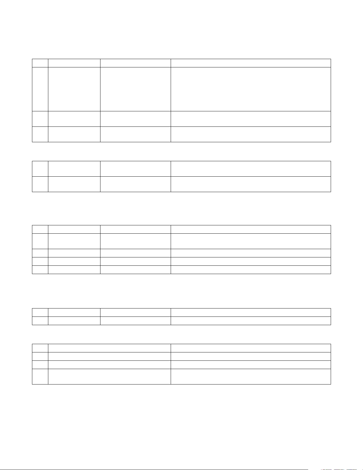
Getting Started
NetMaster Coin Network Adaptable Store Sample Order
Accessory List
Qty Model No. Description Comments
1 EDC100 Micro-Wand Kit EDC108 – Micro-Wand with infra-red adapter cup.
CM1086 – 9-volt rechargeable battery.
CAC203 – Charger/Interface cup enables communication
with computer and recharges battery.
CAC302 – Transformer/power cord supplies power for
recharging battery).
1 CAC202 9 Pin Cable with 25 Pin
Adapter
1 200768 NetMaster Base Software
Suite
Optional Recommended Accessory List
Qty Model No. Description Comments
Links the Micro-Wand and a computer for data transfer.
Program used to generate reports.
1 CAC104 Homebase/Battery
Charger
Provides complete communications and battery charging/
service center, connection to the computer not required.
NetMaster Coin Networked Store Sample Order
Accessory List
Qty Model No. Description Comments
1 200770 Network Software Suite Software used to program networked machines, replaces
Micro-Wand.
1 200768 NetMaster Base Suite Program used to generate reports.
*1 NK100 Desktop Network Card Communicates from computer to networked machines.
*1 NK101 Laptop Network Card Communicates from computer to networked machines.
*The type of network card ordered would depend on the type of computer the store owner is using. These cards
need to be installed by a professional.
Optional Recommended Accessory List
Qty Model No. Description Comments
1 NK120 Repeater Used to network store with 125-249 units.
Accessories Obtained from Local Electronic Supply Store
Qty Description Comments
Twisted Pair Wire, 18 AWG tinned copper Connects networked machines and PC.
1 Computer
1 Wire Cutters/Stripper and a Small
Screwdriver
4 505942
© Copyright, Alliance Laundry Systems LLC – DO NOT COPY or TRANSMIT
Page 7
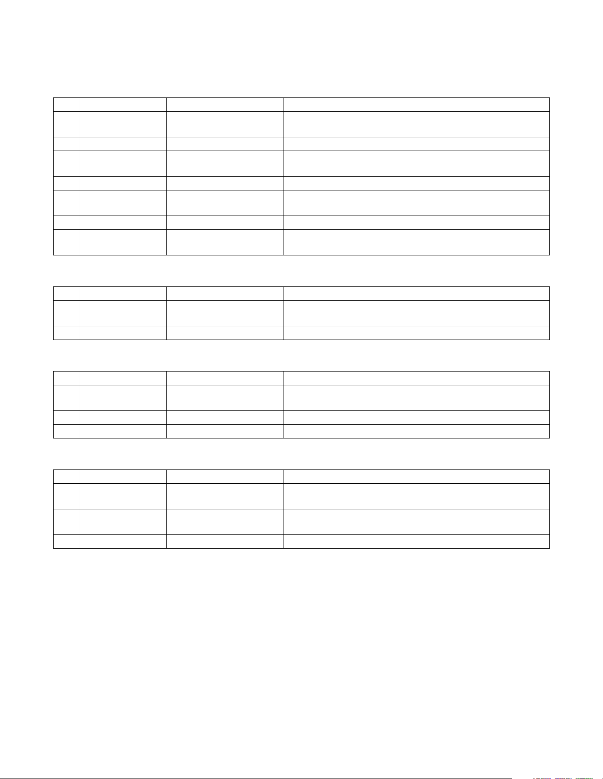
Getting Started
NetMaster CardMate Networked Adaptable Store Sample Order
Accessory List
Qty Model No. Description Comments
2000 200672P User cards Run laundry equipment, between 2000 and 3000 cards are
recommended.
1 S/SITECRDP Master Card Sets site code for CSC and CVC.
1 200771 Smart Card Software
Suite
7 200671 Multi-Purpose Card Can be used to collect data, program or for diagnostics.
1 CM1087 Management reader Used to read, add valve, and service user and multi-purpose
1 200817 SCTM Card Used to access Transaction Module of Smart Card Suite.
1 200768 NetMaster Base Software
Suite
**CSC Accessory List
Qty Model No. Description Comments
1 S/CSC/AVR2 CSC Base Unit With bill acceptor, card reader and recharge balance
1 CSC/CDK CSC Card Dispenser
Program multi-purpose cards. Also read and change value to
user cards.
cards.
Program used to generate reports.
function.
**CVC Unit and Accessories
Qty Model No. Description Comments
1 CVC/BASE/R1 CardMate Value Center
With card reader.
Base Unit
1 CM1077 CVC Bill Acceptor To purchase cards and recharge balance.
1 CVC/CDK CVC Card Dispenser
**CVC Optional Recommended Accessory List
Qty Model No. Description Comments
1 CVC/STAND CVC Stand For floor mounting of the CVC unit. Not needed if mounted
to the wall.
1 CVC/PRK CVC Printer Kit Allows for printing of receipts which is required for credit
card transactions.
1 CVC/PRK/PAPER Thermal Roll Paper Kit For CVC printer (6 rolls).
**Alliance Laundry Systems suggests having at least 2 Card Add Valve Stations. The type and quantity of
Card Add Valve Stations would depend on preferences of the store owner.
505942 5
© Copyright, Alliance Laundry Systems LLC – DO NOT COPY or TRANSMIT
Page 8
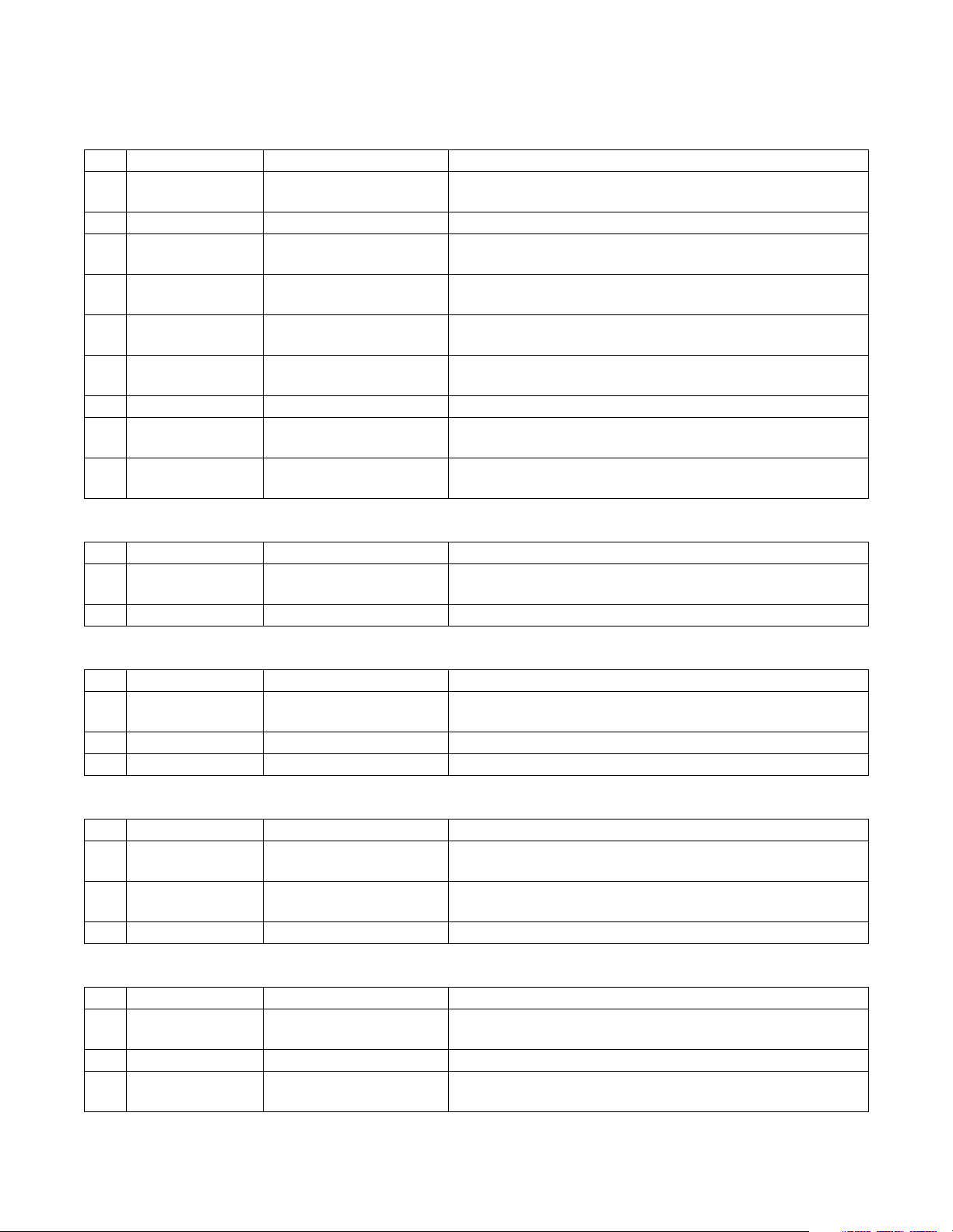
Getting Started
NetMaster CardMate Networked Store Sample Order
Accessory List
Qty Model No. Description Comments
2000 200672P User cards Run laundry equipment, between 2000 and 3000 cards are
recommended.
1 S/SITECRDP Master Card Sets site code for CSC and CVC.
1 200768 NetMaster Base Software
Suite
1 200770 Network Software Suite Software used to run the network. Replaces functions of the
1 200771 Smart Card Software
Suite
1 CM1087 Management Reader Used to read, add valve, and service user and multi-purpose
1 200817 SCTM Card Used to access Transaction Module of Smart Card Suite.
*1 NK100 Desktop Network Card Needed to communicate from computer to networked
*1 NK101 Laptop Network Card Needed to communicate from computer to networked
Program used to generate reports.
Micro-Wand.
Includes Transaction Modules that can read and add value to
user cards.
cards.
machines.
machines.
**CSC Accessory List
Qty Model No. Description Comments
1 S/CSC/AVR2 CSC Base Unit With bill acceptor, card reader and recharge balance
function.
1 CSC/CDK CSC Card Dispenser
**CVC Unit and Accessories
Qty Model No. Description Comments
1 CVC/BASE/R1 CardMate Value Center
With card reader.
Base Unit
1 CM1077 CVC Bill Acceptor To purchase cards and recharge balance.
1 CVC/CDK CVC Card Dispenser
**CVC Optional Recommended Accessory List
Qty Model No. Description Comments
1 CVC/STAND CVC Stand For floor mounting of the CVC unit. Not needed if mounted
to the wall.
1 CVC/PRK CVC Printer Kit Allows for printing of receipts which is required for credit
card transactions.
1 CVC/PRK/PAPER Thermal Roll Paper Kit For CVC printer (6 rolls).
Optional Recommended Accessory List
Qty Model No. Description Comments
7 200671 Multi-Purpose Card Can be used to colect date, program or diagnostics (network
replaces).
1 NK120 Repeater Used to network store with 125-249 units.
1 PC Anywhere Connects your home computer to your store computer.
Bought at local store.
6 505942
© Copyright, Alliance Laundry Systems LLC – DO NOT COPY or TRANSMIT
Page 9

Getting Started
Accessories Obtained from Local Electronic Supply Store
Qty Description Comments
Twisted Pair Wire, 18 AWG tinned copper Connects networked machines and PC.
1 Computer When Alliance Laundry Systems promotion ends.
1 120 Ohm termination Resistor Used on the last machine in the network.
1 Wire Cutters/Stripper and a Small
Screwdriver
*The type of network card ordered would depend on the type of computer the store owner is using. These cards
need to be installed by a professional.
**Alliance Laundry Systems suggests having at least 2 Card Add Valve Stations. The type and quantity if Card Add
Valve Stations would depend on preferences of the store owner.
505942 7
© Copyright, Alliance Laundry Systems LLC – DO NOT COPY or TRANSMIT
Page 10
Notes
8 505942
© Copyright, Alliance Laundry Systems LLC – DO NOT COPY or TRANSMIT
Page 11
Installation
A. Interface PC and Machines
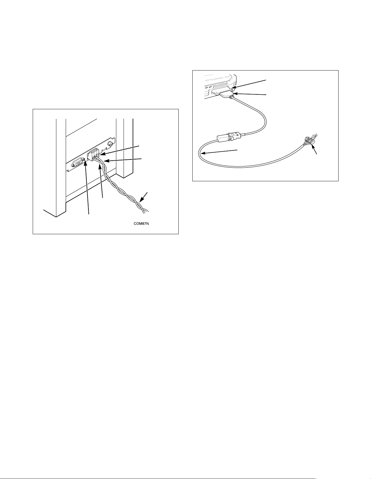
1. The Data Connector should be attached to the
network board on the back of the PC. The PC
must be Pentium 166 or better, have 32 mb
RAM minimum, a CD drive, a mouse and
Windows 98 or higher.
CONNECTOR
BLACK
BLACK AND RED
TWISTED PAIR
WIRE
RED
NETWORK
BOARD
Figure 1
2. Carefully strip 1/4" of the insulation from the
black and red twisted pair wire. If too little
insulation is stripped, and insulation is inside
the connector, the network will not
communicate. If too much is stripped, the wires
will short. Refer to Figure 5.
3. The black/red twisted pair (Alliance Laundry
Systems recommends using American
Electronic Wire Co. part number 781816PFO 2Z) wires should be connected to slots 1 and 2
(red from 1, black from 2). Refer to Figure 6.
DATA
B. Interfacing a Laptop to Machines
NBS-20
CARD
RS-485
CABLE
NETWORK
CABLE
Figure 2
1. Attach the RS-485 cable to the Network Card
and insert the card into the PCMCIA Slot on the
laptop.
2. Attach the network cable to the RS-485 cable.
3. Carefully strip 1/4" of the insulation from the
black and red twisted pair wire. If too little
insulation is stripped, and insulation is inside
the connector, the network will not
communicate. If too much is stripped, the wires
will short. Refer to Figure 5.
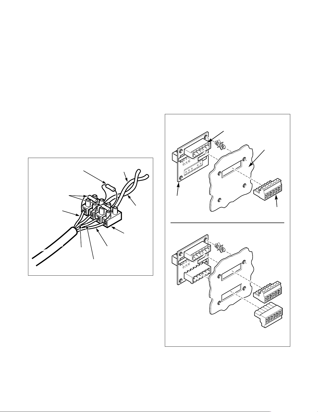
4. Place a 120
2 560
Ω 1/2 Watt terminating resistor and
Ω 1/4 Watt bias resistors into the terminal
strip. Refer to Figure 3.
NOTE: One of the 560
Ω 1/4 Watt bias resistors
connects between the white and red wires of the
network cable. The other 560
Ω 1/4 Watt resistor
connects between the black and green wires of the
network cable.
TERMINAL
STRIP
COM112N
COM112N
505942 9
© Copyright, Alliance Laundry Systems LLC – DO NOT COPY or TRANSMIT
Page 12
Installation
5. Run the wires of the network cable into the
different circuits of the terminal strip and hold
them in place while tightening the screws on
top of the strip. Refer to Figure 3.
6. Carefully strip 1/4" of the insulation from the
black and red twisted pair wire. If too little
insulation is stipped, and insulation is inside the
connector, the network will not communicate.
If too much is stripped, the wires will short.
Refer to Figure 5.
7. Place the black and red twisted pair wire into
the terminal strip and hold the wires in place
while tightening the screw on top of the
terminal strip (connect black wire to black wire
and red wire to red wire). Refer to Figure 3.
NOTE: The 120
Ω 1/2 Watt terminating resistor
connects between the red and black wires of the
twisted pair network wiring.
Ω 1/2 WATT
120
TERMINATING
RESISTOR
BLACK
C. Connecting the Machines to the
PC and Each Other
(For up to 124 machines or 4,000 feet of
network length)
1. Run the black/red twisted pair wire to the first
machine to be connected. Follow whatever
sequence is most convenient for store layout.
Be sure you have DISCONNECTED the PC or
laptop before you begin wiring.
2. Locate the network board header on the back of
the machine. refer to Figure 4
NETWORK
BOARD
HEADER
BACK OF
MACHINE
U
H3
H1
PPER
23456
1
LE
G
/SIN
54321
6
ER
W
LO
Ω 1/4 WATT
560
BIAS RESISTOR
WHITE
RED
Figure 3
BLACK
GREEN
COM1201N
RED
TERMINAL
STRIP
NETWORK
INTERFACE
BOARD
1
1
H
PPER/SIN
U
3
H
6
23456
LE
G
LO
1
5 4 3 2
SINGLE UNITS
ER
W
STACKED UNITS
123456
CONNECTOR
(210099)
123456
123456
CONTROL3a
Figure 4
NOTE: Stacked units will have two connectors.
10 505942
© Copyright, Alliance Laundry Systems LLC – DO NOT COPY or TRANSMIT
Page 13
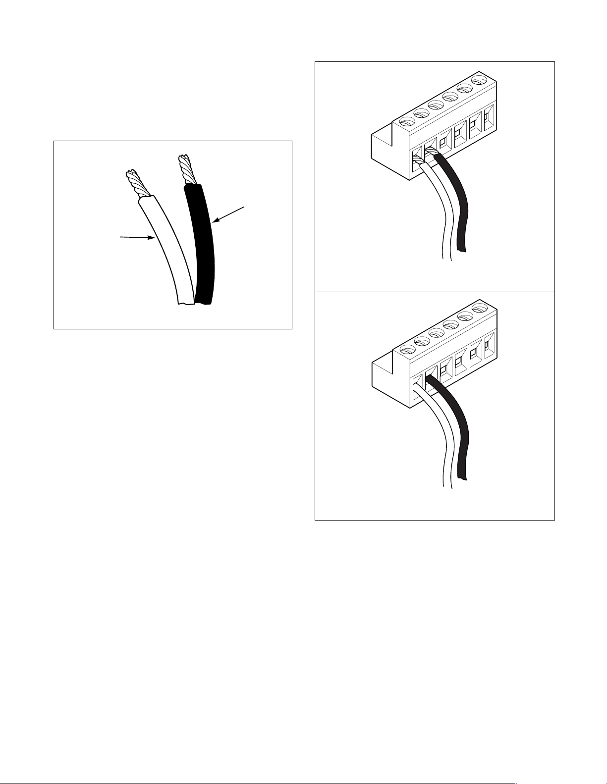
3. Carefully strip 1/4" of the insulation from the
black and red twisted pair wire. If too little
insulation is stripped, and insulation is inside
the connector, the network will not
communicate. If too much is stripped, the wires
will short. Refer to Figure 5.
BLACK
RED
C867i
Figure 5
4. Remove the connector (part number 210099)
from the literature packet or kit.
5. Insert the wire into the connector. The red
incoming wire goes into slot 1 and the black
incoming wire goes into slot 2. Check that only
wire, not insulation is inside the connector.
Incorrect installation could result in the
network not communicating. Secure the wires
in place by tightening the screws on top of the
connector. refer to Figure 6
6. Cut an ample length of wire to reach the next
machine’s connector. The wire should be long
enough to move the machine for maintenance,
but not so long as to interfere with normal
operation. refer to Figure 7
7. Strip 1/4 if the insulation and place the red
outgoing wire into slot 4 and black outgoing
into slot 5. Follow the same procedure in step 5.
8. Connect the wired connector to the Network
Board Header. Refer to Figure 7.
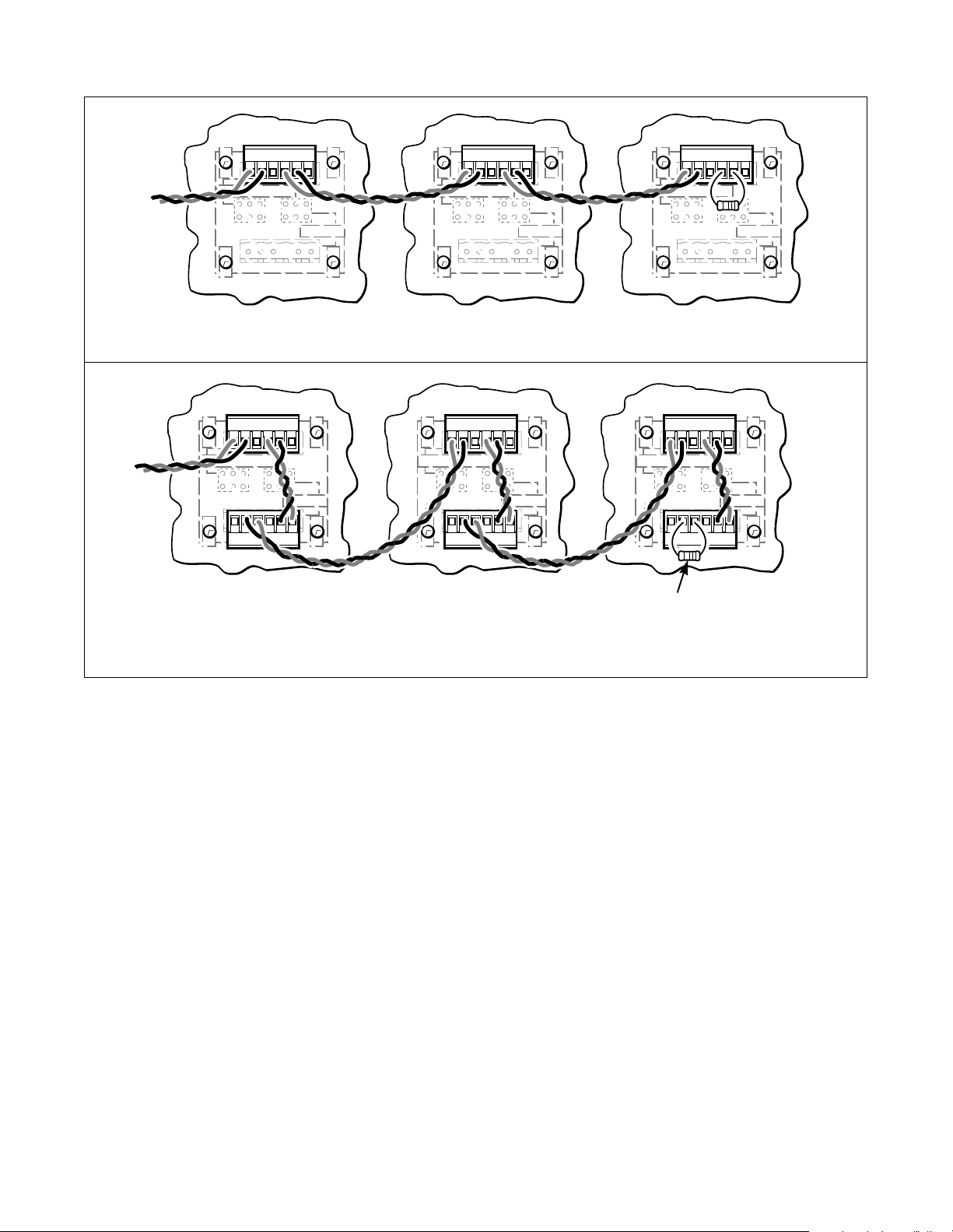
9. Run the wire to the next machine and follow
steps 3-8 until all machines have been
connected. Refer to Figure 7.
10. On the final machine, wires should be run into
slots 1 and 2 as on all previous machines. A 120
Ohm, 1/2 Watt terminating resistor should be
placed in slots 4 and 5 to terminate the
connection at the end of the network. Refer to
Figure 7.
Installation
6
5
4
3
2
1
C758i
CORRECT
6
5
4
3
2
1
C866i
INCORRECT
Figure 6
NOTE: It is recommended that some type of
terminal strip be used when connecting banks of
machines onto a network. This should be done so
that a bank of machines can easily be bypassed in
the network for purposes such as debugging
network problems. A barrier block (such as part
number 210161) may be used for this purpose.
505942 11
© Copyright, Alliance Laundry Systems LLC – DO NOT COPY or TRANSMIT
Page 14
Installation
123456
UPPER/SINGLE
H3
6
54321
LOWER
UPPER/SINGLE
H3
SINGLE UNIT
123456
UPPER/SINGLE
H3
6
54321
LOWER
UPPER/SINGLE
H3
NOTE: For stacked units, wire must be run from
the top connector to the bottom connector before
moving on to the next machine.
STACKED UNIT
123456
6
54321
123456
6
54321
LOWER
LOWER
123456123456 123456
123456
UPPER/SINGLE
H3
6
54321
123456
UPPER/SINGLE
H3
6
54321
TERMINATING
RESISTOR
LOWER
CONTROL1
LOWER
CONTROL2
D. Connecting the Repeater
to the PC
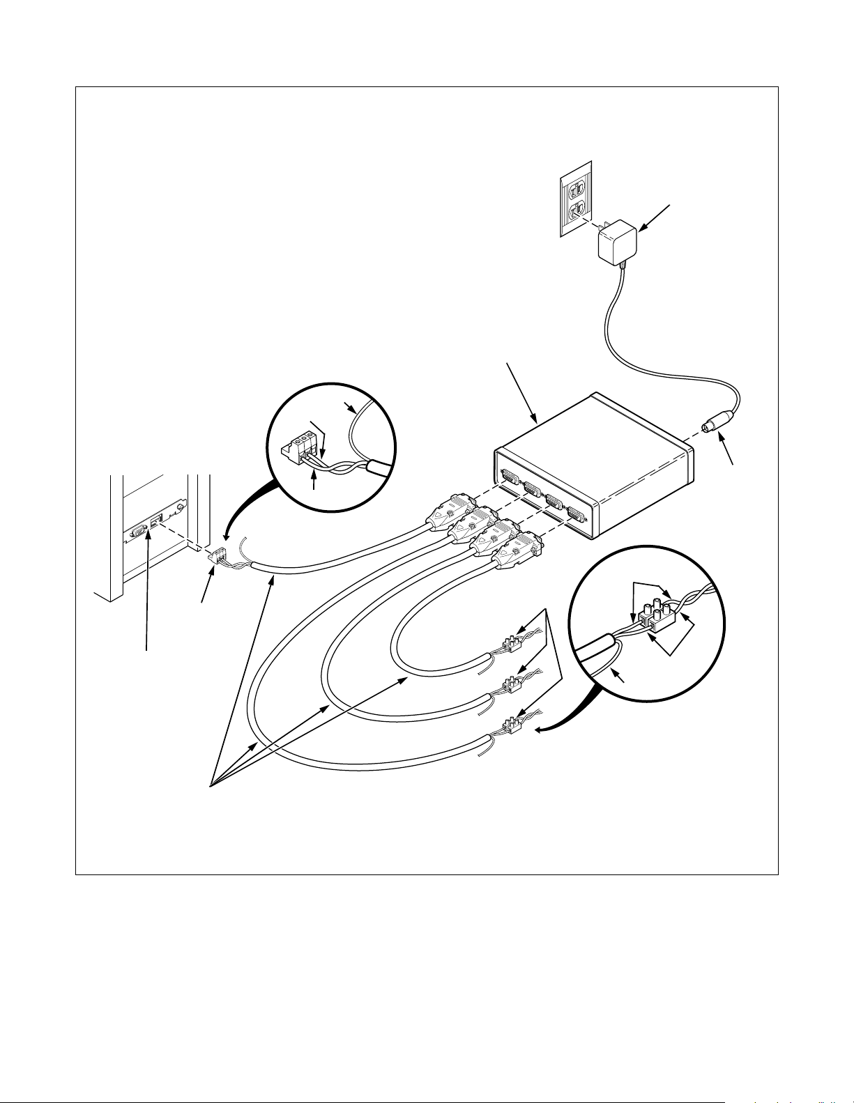
Refer to Figure 8
1. Attach one of the 210150 Network Cables to
segment 1 of the repeater.
2. Connect the RED and BLACK wires of that
Network Cable to the terminal strip coming
from the computer (RED to RED and BLACK
to BLACK). Do not connect the GREEN wire.
3. When repeater is used with a desktop PC, the
bias resistor in the repeaater must be removed.
Open the repeater and remove jumpers J3 and
J4. Refer to the manual included with the
repeater for specific instructions.
NOTE: Ensure that only the bias resistors that
correspond to segment one (PC connection) are
removed.
4. Connect one of the 210150 Network Cables to
segment 2 of the repeater.
Figure 7
5. Connect the RED and BLACK wires of that
Network Cable to the terminal strip going out to
one leg of the network (RED to RED and
BLACK to BLACK). Do not connect the
GREEN wire.
6. Terminate the last machine on this leg with a
120 Ohm 1/2 Watt resistor.
NOTE: Up to 124 nodes may be connected to any
given segment coming off the repeater. A total of
250 nodes may be connected to the network.
7. Repeat steps 4 – 6 for the remaining 2 segments
as required. There is no need to connect a cable
or a terminating resistor to an unused segment
on the repeater.
8. Connect the bayonet style connector of the wall
adapter to the 12 VDC input on the repeater.
9. Connect the wall adapter to a 120 VAC 60 Hz.
outlet.
12 505942
© Copyright, Alliance Laundry Systems LLC – DO NOT COPY or TRANSMIT
Page 15
To Connect Repeater to PC
REPEATER
GREEN
BLACK
Installation
WALL
ADAPTER
(120 VOLT)
NBS-42
CARD
DATA
CONNECTOR
NETWORK
CABLE
(210150)
RED
TERMINAL
STRIP
RED
GREEN
BLACK
COM210N
COM210N
12 VOLT
DC
Figure 8
505942 13
© Copyright, Alliance Laundry Systems LLC – DO NOT COPY or TRANSMIT
Page 16
Installation
E. Connecting the Repeater
to a Laptop
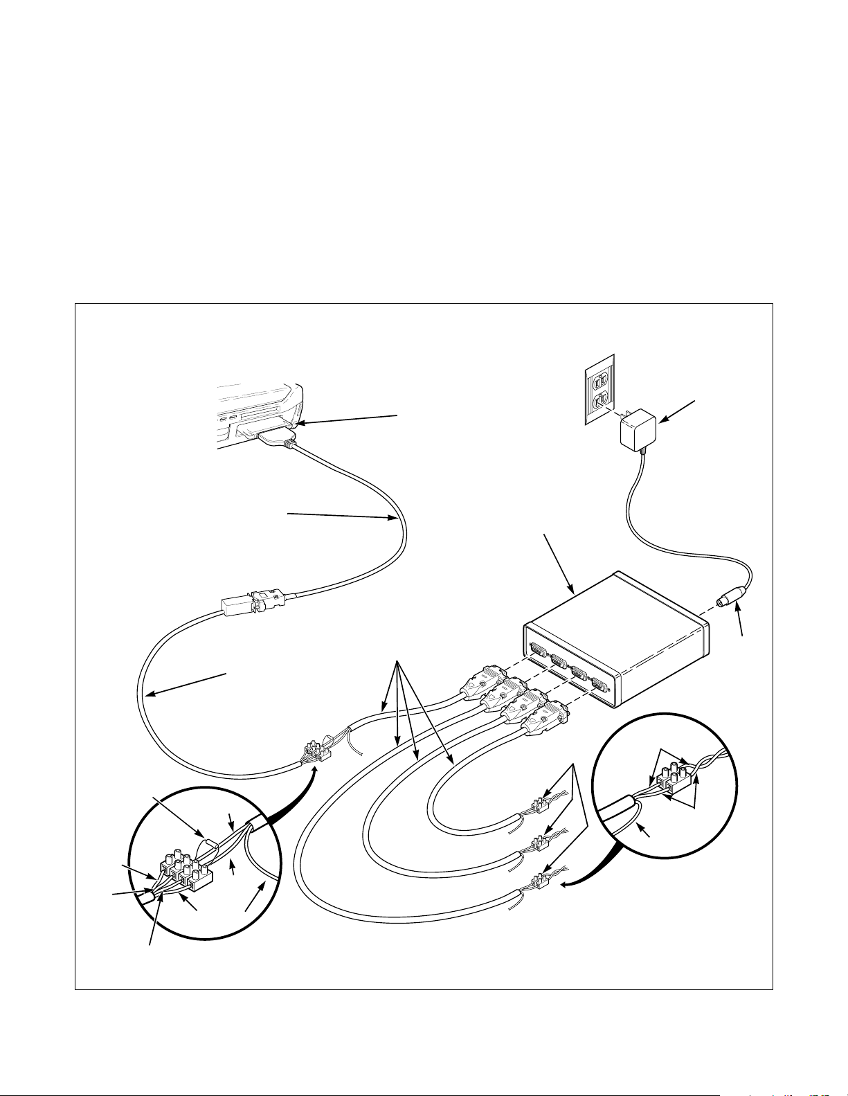
NOTE: If connecting the repeater to a laptop, a
terminating resistor must be used. Refer to the
section on “Interfacing a Laptop to Machines” on
page 5. Refer to Figure 9.
F. Tests
Once the network has been wired, run the
following tests to ensure proper installation.
To Connect Repeater to Laptop
NBS-20
CARD
1. Power off all machines before test.
2. Check for continuity of 2 wires running from
the central PC.
a. Disconnect the wires from the PC
b. Check for 120
Ω ± 20%. A much higher
reading indicates an open circuit. This is
caused by a break in the network. A much
lower reading indicates a short in the
network, which means the network is only
communicating to a certain point in the
network.
WALL
ADAPTER
(120 VOLT)
120 Ω
1/2 WATT
TERMINATING
RESISTOR
WHITE
RED
BLACK
NETWORK
RED
BLACK
GREEN
RS-485
CABLE
(210165)
NETWORK
CABLE
(210150)
REPEATER
TERMINAL
STRIP
12 VOLT
DC
RED
BLACK
GREEN
COM1047N
Figure 9
14 505942
© Copyright, Alliance Laundry Systems LLC – DO NOT COPY or TRANSMIT
Page 17
Troubleshooting
Error Codes
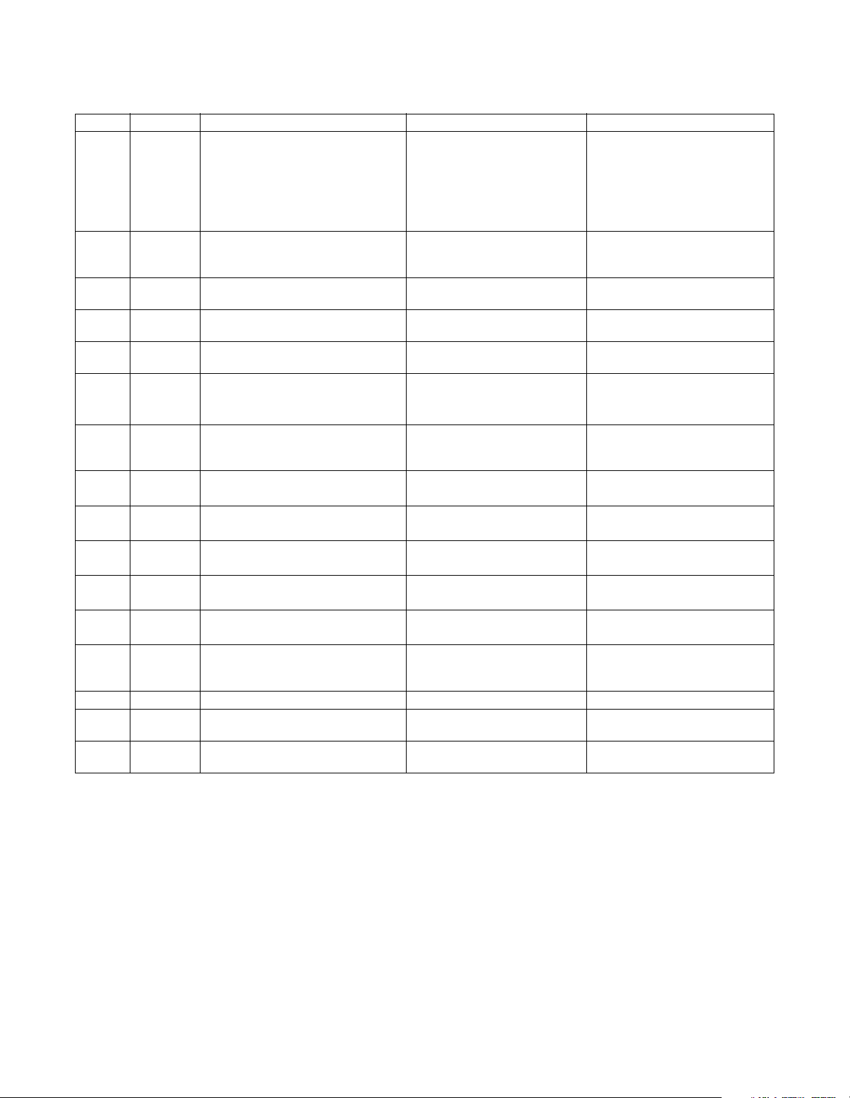
Display Machine Error Description Error Cause Error Condition Exit
“EI:xx”
“EC:xx”
:03 - Invalid command code - Wrong machine type
:05 - Invalid or out-of-range data - Wrong machine type
:06 - Invalid data code - Wrong machine type
:09 - Corrupted data error - Communication problem
:0A - Invalid machine type - Wrong machine type
:19 - No Card Reader communication - Communication problem Good communication ends
:20 - Unreadable card - Bad card/dirty contacts
:21 - Security ID mismatch - Card ID mismatch
:22 - Site code mismatch - Card site code mismatch
:23 - Card maximum value exceeded - Value on card over max
:24 - Insufficient memory on card - Card’s memory full
:25 - Card reader malfunction - Bad card reader
:26 - Card write error - Bad card
:27 - Diagnostic test card write failure - Bad card reader
:28 - Diagnostic test card read failure - Bad card reader
:29 - Diagnostic test memory test
:2A - Diagnostic test card interface
:2b - Diagnostic test flash checksum
:2C - Bad Biberon or non-Biberon
:2d - Firmware update failed, s/w
:2E - Firmware update failed, s/w not
:2F - Firmware updated, but s/w not
All
:00 - General communication error - Communication problem
:01 - Bad transmission - Communication problem
:02 - Device timeout - Communication problem
:03 - Invalid command code - Wrong machine type
:04 - Expecting upload request - Communication problem
:05 - Invalid or out-of-range data - Wrong machine type
:06 - Invalid data code - Wrong machine type
:07 - Error writing to RTC - Control failure
:08 - Error writing to EEPROM - Control failure
:09 - CRC-16 error - Communication problem
:0A - Invalid machine type - Wrong machine type
:0F - Invalid wakeup or IR disabled - Communication problem or
All
:00 - General communication error - Communication problem
:02 - Timeout error - Communication problem
IR Communication Errors:
Error ends after several
seconds
IR is disabled
Card Reader Communication Errors:
Error ends after several
seconds (unless specified
differently)
error
- Bad card reader
failure
- Bad card reader
failure
- Bad card reader
failure
- Bad card reader
device
- Firmware load failed
intact
- Bad firmware in reader Loading valid FW ends error
intact
- Bad firmware in reader Loading valid FW ends error
intact
505942 15
© Copyright, Alliance Laundry Systems LLC – DO NOT COPY or TRANSMIT
Page 18
Troubleshooting
Error Codes (continued)
Display Machine Error Description Error Cause Error Condition Exit
:30 - Timeout waiting for Biberon
insertion
:31 - Hotlisted card inserted into the
reader
:50 - Loyalty purse read error - Bad card
:56 - Loyalty purse write error - Bad card
Rightmost
dp lit
“Err”
“Alrm”
“OFF”
“E:FL”
All
All
All
All
Topload
- Network communication error - Communication problem Error ends at good
- Coin error - Invalid coin pulse(s) Error ends after several
- Breakin alarm error - Service door or coin vault
- Breakin alarm shutdown error - Service door or coin vault
- Fill error - Maximum fill time exceeded Cycle power to clear error
Frontload
WX
“E:dr”
Topload
- Drain error - Maximum drain time
WX
“E:SP”
Frontload
- SPI communications error - Internal communication
WX
“E:OP”
Dryer
- Open temperature sensor error - Bad sensor or wiring Cycle power to clear error
WX
“E:SH”
Dryer
- Shorted temperature sensor error - Bad sensor or wiring Cycle power to clear error
WX
“E:dL”
Frontload
- Door lock error - Unable to lock or unlock the
WX
“E:dO”
Frontload
- Door open error - Door opened during a
WX
“E:Ub”
Frontload
- Unbalance error - Unable to balance a load Error cleared after EOC (FL)
WX
“E:dF”
“E:HT”
“E:Pr”
WX
WX
WX
- Motor failure error - Motor failure Cycle power to clear error
- Heater error - Maximum heat time
- Pressure switch sequence error - Pressure switches out of
- Bad firmware in reader
- Card hotlisted After control destroys card, the
error is cleared
communication
seconds
Error ends after several
switches
switches
exceeded or water sensed at
end of a spin step
problem
loading door
running cycle
exceeded
sequence
seconds
Cycle power to clear error
Cycle power to clear error
Cycle power to clear error
Error cleared when door lock
condition is corrected
Cycle power to clear error
Error cleared after 1 min.
(WX)
Cycle power to clear error
Cycle power to clear error
16 505942
© Copyright, Alliance Laundry Systems LLC – DO NOT COPY or TRANSMIT
Page 19

Network Interface Boards
Troubleshooting
Wire Break - Any time there is a wire break on the
network, all machines on the opposite side of the break
from the Central PC will become unable to
communicate with the Central PC. Also,
communication may become less reliable for those
nodes which are still on the network, since the
terminating resistor on the end of the network has been
separated from the network.
Short on the Line or on the Network Board - If
there is ever a short on the network, the entire network
may be unable to function. However, if the short is on
the far end of the network, those nodes closest to the
Central PC may be able to communicate with the
Central PC to some degree.
Shorts may be isolated by removing the RS-485 cable
from the PC, and putting an Ohm-meter on the cable.
Next, remove a series of machines at the end of the
network, and check the meter. If there is no longer a
short, the short is somewhere in the chain of machines
removed from the network. If there is still a short, move
the break in the network close to the Central PC until a
location is found where the short can be eliminated. By
repeating this process of elimination, a short in either
the cable or on a network board may be isolated.
Wires Flipped on the Network - Correct polarity
must be observed when installing machines on the
network. If a machine is installed with the wrong
polarity at either the input or output (but not both) at the
connecting terminals, all machines further down the
series will be unable to communicate with the Central
PC. If, however, both the input and output are wired
incorrectly, only that machine will be unable to
communicate. If the wires at the card on the PC are
flipped, none of the machines will be able to
communicate with the Central PC.
NOTE: Both shorts or flipped wires will cause
numerous errors on the central PC, including
“Protocol Errors” and numerous “Unable to
Connect” messages.
Nodes on the Same Address - If two or more nodes
share the same address, there will be intermediate
levels on the network, which may be observed with an
oscilloscope. These intermediate levels will occur
whenever the Central PC commands a response from
the address at which there are multiple nodes. In most
cases, the Central PC will not be able to communicate
successfully with any of the devices at this address. In
some cases, however, if two nodes share the same
address with one close to the Central PC and the other
on the opposite end of the network, the node closest to
the PC may be able to overpower the other, and
complete a valid communication. The one at the far
end, in this case, will not be able to communicate at all
with the Central PC.
NOTE: Nodes on the same address will cause
numerous errors on the central PC, including
“Protocol Errors” and numerous “Unable to
Connect” messages.
Jabbering Node - In this condition, a node on the
network is transmitting erratically. If the node is
transmitting constantly, this condition may bring down
the entire network. In other cases, it may transmit
periodically. If this is the case, some communications
will be able to get through, until the node begins
jabbering again. A jabbering node may be detected by
disconnecting the network from the PC and monitoring
the network with an oscilloscope. Since the PC initiates
all communications, the scope should show no
communications once the PC is removed. If the scope
indicates that there is communication occurring,
individually remove each node from the network and
use the scope to check for communication from that
node.
NOTE: Jabbering nodes will cause numerous
errors on the central PC, including “Protocol
Errors” and numerous “Unable to Connect”
messages.
505942 17
© Copyright, Alliance Laundry Systems LLC – DO NOT COPY or TRANSMIT
Page 20
Troubleshooting
Card Reader
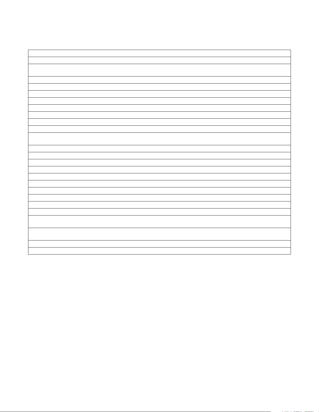
Display Error Description Corrective Action
EC:00 - x See EC:19 See sheet on EC:19.
EC:02 Communication Time-Out If transaction did not go through, try again.
EC:03 Invalid Command Code If received with a cash value card, try again. Otherwise, card
contains an invalid command.
EC:05 Invalid or Out-of-Range data Make sure data on programming card is for the current machine.
EC:06 Invalid Data Code Make sure data on programming card is for the current machine.
EC:09 CRC error Try again.
EC:0A Invalid machine type Make sure data on programming card is for the current machine.
EC:19 - x No Card Reader Communication See section on EC:19.
EC:20 Unreadable card See section on EC:20.
EC:21 Security code ID mis-match Use a card with a security code equal to that in the machine.
EC:22 Site Code mis-match Use a card with a site code equal to that in the machine.
EC:23 Card Max value exceeded Use a card with a value less than the card max value programmed in
the reader.
EC:24 Insufficient memory on card Download card contents and clear card to do further collects.
EC:25 Card reader malfunction Try again. Card reader may need to be replaced.
EC:26 Card write error See sheet on EC:26.
EC:27 Diagnostic test card write error Try again. Card reader may need to be replaced.
EC:28 Diagnostic test card read error Try again. Card reader may need to be replaced.
EC:29 Diagnostic test memory test error Try again. Card reader may need to be replaced.
EC:2A Diagnostic test card interface error Try again. Card reader may need to be replaced.
EC:2B Diagnostic test flash checksum error Try again. Card reader may need to be replaced.
EC:2C Bad Biberon or non-Biberon device Firmware must be reloaded into reader with a Biberon.
EC:2D Firmware update failed, software intact See firmware loading.
EC:2E - x Firmware update failed, software not
intact
EC:2F - x Firmware updated, but software not
intact
EC:30 Time-out waiting for Biberon insertion See firmware loading.
EC:31 Hotlisted card inserted into the reader Card inserted into the reader was on the hotlist. Card destroyed.
See firmware loading.
See firmware loading.
NOTE: Errors marked with an "X" remain on the display until the error condition is cleared. All other
errors are displayed temporarily, for approximately 2 seconds.
18 505942
© Copyright, Alliance Laundry Systems LLC – DO NOT COPY or TRANSMIT
Page 21

Troubleshooting
Card Insertions not recognized by the card reader
All card insertions should be reflected on the FEC
display in some manner. For example, if a valid cash
card is inserted into the reader, the FEC display should
show the balance on the card.
A simple test is to insert any non-smart card (credit
card, etc.) into the reader. The display should display
an EC:20. This indicates that the reader recognizes a
card has been inserted, but it cannot read it. Also this
verifies that the reader is communicating successfully
with the Front-End Control (FEC).
If the card insertions are not reflected on the FEC
display, one of the following conditions has occurred:
• Card reader harness not hooked up or wired
incorrectly.
• Card reader is not recognizing card insertions.
• Card reader is not capable of communicating with the
FEC.
• If a network board is present, it has malfunctioned.
• FEC has malfunctioned, and is not supplying power
to the reader.
• FEC has malfunctioned, and is not capable of
communicating with the reader.
If the FEC senses that a card reader is present and the
reader fails to communicate with the FEC, it will
display an EC:19 error after 2-1/2 minutes. However, if
the FEC never recognized that the reader was present at
power-up, there will be no error displayed to indicate
that there is no communication with the reader.
EC:19
NOTE: An EC:19 error indicates that the FEC
recognizes that there is a Card Reader present, but
it has not received a communication from it in the
last 2-1/2 minutes.
Network Board Present - If a Network Board (NWB)
is present, it is possible that it has malfunctioned. A bad
NWB can prevent the reader from communicating with
the FEC, resulting in an EC:19. Before powering down
the unit, examine the LED on the NWB. If the LED is
NOT flashing one second on/one second off, it is not
functioning correctly. It will need to be either reset ( by
powering down then up again) or replaced.
If a Network Board is present, it is helpful to eliminate
it, if possible, from the circuit temporarily for
troubleshooting purposes. Unplug the harness from the
NWB to the Card Reader, and also unplug the harness
from the NWB to the FEC. Next, connect the harness
which is used to connect a Card Reader directly to the
FEC.
NOTE: This harness is not included in machines
containing a NWB. The individual performing the
service to the machine will have to have this
harness.
If the EC:19 disappears once the NWB has been
removed (allow approximately 120 seconds), the NWB
may need to be replaced, since the reader was able to
communicate with a direct link to the FEC. Ensure that
the reader is now operating properly by inserting
several cards in the reader, and looking for the
appropriate response on the FEC display.
Once the NWB is removed from the circuit, continue to
"NWB Not Present" below.
Network Board Not Present - Begin by checking the
voltage to the card reader. The following
measurements should be taken at the 14-pin header on
the card reader. There should be between 24 and 38
volts DC across pins 3 and 12. This voltage must be
present, or the reader will not operate. Also, there
should be 5 volts DC across pins 10 and 12. This
voltage must be present, or the FEC will not recognize
that the card reader is present.
If the voltages mentioned above are found to be present
at the reader’s 14-pin header and the reader is not
functioning correctly, the harness may be bad, the FEC
may be bad, or the card reader may be bad.
First, disconnect the reader from the 14-pin header, and
re-connect it. Wait about 20 seconds. If there was an
EC:19 on the display, check the FEC display to see if
the EC:19 has gone away. If it has, the communication
has been re-established. The card reader may have
experienced a lock-up condition, and should run fine
once it has been reset by powering down and up again.
Whether or not there was originally an EC:19 on the
display, try several cards in the reader to ensure correct
operation.
505942 19
© Copyright, Alliance Laundry Systems LLC – DO NOT COPY or TRANSMIT
Page 22

Troubleshooting
If the EC:19 does not clear or the FEC display still does
not reflect a card insertion, try substituting the harness
from the FEC to the reader with a known good harness.
Wait about 20 seconds. Check the FEC display to see
if the EC:19 goes away, and that FEC does reflect the
card insertions. If both conditions are satisfied, the old
harness was bad, and the new one should be used to
replace it. Try several cards in the new reader to ensure
correct operation.
If the EC:19 does not clear or the FEC display still does
not reflect a card insertion, try substituting another card
reader. Wait about 20 seconds. Check the FEC display
to see if the EC:19 goes away, and that FEC does
reflect the card insertions. If both conditions are
satisfied, the old reader was bad, and the new one
should be used to replace it. Try several cards in the
new reader to ensure correct operation.
If substituting with a new known good reader and a
new known good harness does not clear the EC:19 and
allow card insertions to be displayed by the FEC, the
Front-End Control will probably need to be replaced.
EC:20 – Error Reading Card
EC:26 – Card Write Error
EC:26 errors can occur in cases where neither the
reader and the card which caused the EC:26 are faulty.
This can occur for the following reasons:
• The reader and card contacts are not making a good
connection due to dirty contacts.
• Intermittent poor connections.
• The user not inserting the card properly.
Therefore, it is necessary to try numerous cards
numerous times before deciding whether an individual
card or reader is in need of replacing.
If an EC:26 error occurs once on a given card, and does
not happen again in later transactions, the card and
reader are probably OK, and neither would need to be
replaced.
If a given card repeatedly gives EC:26’s, the card will
need to be replaced.
If a given reader repeatedly gives EC:26’s with a
variety of cards, the reader will need to be replaced.
EC:20 errors can occur in cases where neither the
reader and the card which caused the EC:20 are faulty.
This can occur for the following reasons:
• The reader and card contacts are not making a good
connection due to dirty contacts.
• Intermittent poor connections.
• The user not inserting the card properly.
Therefore, it is necessary to try numerous cards
numerous times before deciding whether an individual
card or reader is in need of replacing.
If EC:20’s are consistently received on an individual
card, but not on others, the card which gives the errors
may need to be replaced
If EC:20’s occur often with different cards, the card
reader’s contacts should be cleaned. If, after cleaning,
the problem persists when numerous cards have been
tried numerous times, the reader is not reading cards
properly and should be replaced.
Other Errors
The following errors should only occur if a firmware
load has been attempted on the card reader. Under any
other condition, if an EC:2A, EC:2C, EC:2D, EC:2E,
EC:2F or EC:30 appears, the reader should be replaced.
20 505942
© Copyright, Alliance Laundry Systems LLC – DO NOT COPY or TRANSMIT
Page 23
Troubleshooting
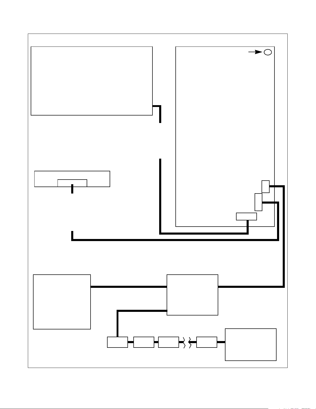
FRONT END CONTROL (FEC)
Power requirements for operation:
24 VAC ± 4 VAC Between pins 1 & 2 at header H1.
Function:
Supplies power to the NWB and Card Reader.
24 - 38 VDC Between pins 3 & 12 at header H6.
5 VDC Between pins 2 & 12 at header H6.
Stores a programmable node address, which overwrites the default network address on the NWB.
NOTE: Use different node address for each FEC.
CARD READER
Power requirements for operation:
24 - 38 VDC Between pins 3 & 12.
Function:
Reads data from the smart card and
sends it to the NWB.
Receives data from the NWB and
Control Harness
Passes power from the
FEC to the NWB.
Passes data between the
FEC and the NWB.
writes data on to the smart card.
AND
NETWORK CONTROL BOARD (NWB)
DIAGNOSTIC LED
Power requirements for operation:
24 VAC ± 4 VAC Between pins 6 & 7 at
header H1.
5 VAC ± .5 VAC Between pins 1 & 2 at
header H1
Function:
Receives data from the network and passes
it on to the FEC.
Receives data from the card reader and
passes it on to the FEC.
Receives data from the FEC and passes it
on to the card reader
Provides operational diagnostics through
the LED.
See section 1.0 for LED diagnostic details.
Has a default node address of 250.
H3
Card Reader Harness
Passes power from the NWB
to the card reader.
AND
Passes data between the NWB
and the card reader.
COMPUTER
Operator interface to the
network. Reads data
received from the network
and passes data to
machines on the network.
Requires each machine to
have a separate node
address.
NETWORK INTERFACE
BOARD (NIB)
Network Harness
Passes data to and from the
network to the machine.
Links all machines
together through the
NIB's and place
individual machine data
on one communication
bus.
(NIB) (NIB) (NIB) (NIB)
H2
H1
Network Interface Harness
Passes data to and from the
network to the machine.
Last (NIB) on the
network requires an 120
Ohm terminating
resistor for proper
communication.
Figure 10
505942 21
© Copyright, Alliance Laundry Systems LLC – DO NOT COPY or TRANSMIT
Page 24

Troubleshooting
Network Board Service
Commonly Used Abbreviations:
FEC - Front-End Control – the Dryer/Tumbler
Control, Top-Load Washer Control, Front-Load
Washer Control, and Washer/Extractor Control are all
referred to simply as the Front-End Control throughout this document
NWB – Network Board
NIB – Network Interface Board
LED – Light Emitting Diode
Network Board LED
When the operation of the Network Board is suspect,
the state of the LED may be examined to determine
whether the Network Board is operating properly.
Network Board Operating LED Test
LED is Flashing One Second On / One Second Off -
This is what the LED should be doing in normal
operation. If the LED is following this sequence, the
processor on the board is executing the code correctly.
However, there may still be other problems with the
board.
LED is Constantly Off - If the LED is constantly off,
there is probably no power to the NWB. There must be
24VAC across pins 6 & 7 on header H1 for the NWB
to operate. If there is 24VAC across pins 6 & 7 and the
LED is a constant off, the NWB will need to be
replaced.
LED is Flashing Rapidly or is Constantly On - If
the LED is constantly on or is flashing rapidly or
erratically, the NWB may be in a lock-up state or may
be bad. Remove power from the board by pulling
header H1, and then put the header back again. If the
LED begins to flash one second on / one second off, the
board is probably OK. If this does not happen, the
NWB will need to be replaced.
LED Flashes Rapidly 3 Times - This sequence
indicates the beginning or end of a communication
sequence with the FEC. The service personnel may
determine if the NWB is communicating with the FEC
by following the procedure in the following section.
Network Board Communicating LED Test
Test of Communications Between FEC and NWB
Using LED -
header H1. Re-connect H1. Approximately 15
seconds after H1 is reconnected
(7 LED flashes), the LED should flash rapidly 3 times,
indicating that it is beginning communication with the
FEC. Two LED flashes later, the LED should flash
rapidly 3 times again, indicating the end of a successful
communication sequence. If this does not occur, the
NWB is not communicating with the FEC.
Once it has been determined that the processor on the
NWB is correctly executing the NWB code, the service
personnel may now check for the following other
possible malfunctions of the NWB (and/or the FEC).
• NWB is not communicating with the FEC
• NWB is not allowing the Card Reader to
communicate with the FEC
• NWB is not communicating with the PC
Power down the NWB by disconnecting
Network Board to Front-End Control Communication Problems
NWB will not Communicate with FEC - If the NWB
is not communicating with the FEC, the NWB, FEC, or
Harness may be at fault. For the following cases, use
the Network Board Communicating LED test
previously described to test the communication link
between the FEC and the NWB using the LED.
The FEC must supply 5 VDC to the NWB via pins 1 &
2 on H1 for the NWB to function correctly. If the
5VDC is not present, the NWB can in no way
communicate with the FEC. If this voltage is not
present, the harness or the FEC may be at fault.
If there is 5VDC across pins 1 & 2 of H1 and the NWB
will not communicate with the FEC, swap the harness
between the FEC and NWB with an known good
harness. If this fixes the problem, the harness is at
fault.
If the harness is not at fault, the NWB should be
swapped with a known good board. If this fixes the
problem, the NWB needs to be replaced. If after
changing out the NWB and the harness with known
good samples the NWB will not communicate with the
FEC, the FEC must be at fault.
In general, there are three possible sources of failure,
the NWB, the FEC, and the Harness. Parts may need
to be swapped out individually to isolate the problem.
22 505942
© Copyright, Alliance Laundry Systems LLC – DO NOT COPY or TRANSMIT
Page 25

Troubleshooting
Network Board Blocks Card Reader
Communications to FEC -
Some failure modes may
prevent the card reader (if connected) to communicate
with the FEC. If this is the case, the NWB itself may
or may not be able to communicate with the FEC.
To eliminate the possibility of a bad reader, it is helpful
to temporarily eliminate the NWB from the circuit.
Unplug the harness from the NWB to the card reader,
and also unplug the harness from the NWB to the FEC.
Next, connect the harness which is used to connect a
card reader directly to the FEC.
NOTE: This harness is not included in machines
containing a NWB, the individual performing the
service to the machine will have to have this
harness.
Once the card reader is linked directly to the FEC, wait
15 seconds, and insert any card into the reader. The
FEC display should change to reflect the card insertion.
If the FEC does not indicate that a card was inserted,
the NWB may not be the problem. In this case, see the
section on Card Readers.
If the card reader does communicate the card insertion
to the FEC, remove the temporary harness and put the
original harnesses back in place, so that the NWB is
once again in the circuit.
Next, swap the harness from the NWB to the card
reader with a known good harness. If the reader is now
able to communicate a card insertion, the harness is at
fault, and must be changed. If not, put the original
harness back, and continue.
Check that there is 5 VDC across pins 1 & 2 of H1 on
the NWB. If this voltage is not there, communication
between the FEC and the card reader or NWB will not
occur.
If there is 5VDC across pins 1 & 2 of H1 and the card
reader cannot communicate with the FEC, swap the
harness between the FEC and NWB with an known
good harness. If this fixes the problem, the harness is
at fault.
If the harness is not at fault, the NWB should be
swapped with a known good board. If this fixes the
problem, the NWB needs to be replaced. If after
changing out the NWB and the harness with knowngood samples the card reader cannot communicate with
the FEC, the FEC must be at fault.
Network Board to PC Communication Problems
Communication between the NWB and the PC may be
interrupted via several cases:
• NWB not operating correctly (not executing
program)
• NWB cannot communicate with FEC (NWB cannot
get its correct node number)
• Problems on network external to the NWB under test
- Wires flipped at one or more points on the Network
- Short on the Network
- Noise on the Network (another node jabbering,
reflections, etc.)
NWB Not Operating Correctly - If the NWB is not
executing the code in the processor correctly, there is
no way it can communicate with the FEC. Use the
network board operating LED test and the network
board communicating LED test to verify operation.
NWB Cannot Get Node Number From PC - If this is
the case, the PC should be able to communicate with
the NWB by attempting to communicate with node
250. Note that since 250 is the default node in the
NWB, if it cannot retrieve another node number from
the FEC, it will default to 250. When running this test,
remember that there may be other nodes on the
network, due to other failures, that may result in more
than one node 250 on the network. If this is the case,
the PC may not be able to get through to any node
numbered 250. Because of this, it is desirable, if
possible, to perform this test on a “1-node” network,
which contains only the NWB under test.
If the PC can communicate with the NWB as node 250,
then either the FEC has node number 250 programmed
into it (test via the Microwand), or the NWB is not
communicating with the FEC. Use the network board
communicating LED test to verify operation.
Problems Related to Network - If possible, it may be
beneficial to isolate the NWB in question from the rest
of the network, creating a “1-node” network. This
eliminates other network boards, mis-wiring on the
network, etc., as causes for a NWB not communicating
with the PC.
With the NWB alone connected to the PC, attempt to
communicate with the board. If no communication
occurs at any node number, the NWB or the harness
from the NWB to the connector at the rear of the
machine is bad. Try swapping the NW cable from the
rear connector to the NWB and test again. If
communication is successful, the harness needs to be
replaced.
505942 23
© Copyright, Alliance Laundry Systems LLC – DO NOT COPY or TRANSMIT
Page 26
Notes
24 505942
© Copyright, Alliance Laundry Systems LLC – DO NOT COPY or TRANSMIT
 Loading...