

Page 1
Cylinder ironer
Strijkmangel
CI 1650/325
CI 2050/325
Technical specications
Technische gegevens
Installation instructions
Installatie
Operating instructions
Gebruiksaanwijzing
Maintenance
Onderhoud
Handleiding
Handleiding
Instruction manual
Instruction manual
Part No. D1088
Code: 249/00277/00
October 2003
Page 2

TECHNIISCHE HANDLEIDING
Beschrijving van het product en het
instructies en indien
Informatie betreffende het juiste gebruik
Instructies voor de inwerkingstelling
Beschrijving van de machinefuncties,
systeem
alsmede de bedieningsinstructies voor
CHAPTER I- IX
IRONER CI325
TABLE OF CONTENTS
This MANUAL is divided into chapters. Each
chapter has its own table of contents.
Deze HANDLEIDING is in hoofdstukken
opgedeeld. Elk hoofdstuk heeft een eigen
inhoudsopgave.
TECHNISCHE HANDLEIDING
HOOFDSTUK I -IX
INHOUDSOPGAVE
Chapter
PRODUCT DESCRIPTION I
Description of the product and its use,
technical data, warranty and service
instructions, and if necessary
declaration of conformity
OPERATION III
Information on the correct use of the
machine
SETUP AND ADJUSTMENT OF
IV
MACHINE
Instructions on first start-up of the
machine
MACHINE FUNCTION,
V
ADJUSTMENT AND TROUBLESHOOTING
Description of machine functions,
adjustments and trouble -shooting
Hoofdstuk
PRODUCTBESCHRIJVING I
gebruik, technische gegevens, garantie- en servicenodig, een conformiteitsverklaring
BEDIENING III
van de machine
INSTALLATIE EN AFSTELLING
IV
VAN DE MACHINE
van de machine
MACHINEFUNCTIE, AFSTELLING
V
EN STORINGZOEKEN
afstellingen en storingzoeken
DESCRIPTION OF CONTROL
SYSTEM
Description of the control system and
instructions for operating panel
MAINTENANCE VII
Information on regular maintenance
SPARE PARTS VIII
Procedure for ordering spare parts and
spare parts list
MACHINE DOCUMENTS IX
can contain:
Wiring diagrams
Factory setting
Technical description
VI
BESCHRIJVING VAN HET
VI
BESTURINGSSYSTEEM
Beschrijving van het besturinghet bedieningskastje
ONDERHOUD VII
Informatie over regelmatig onderhoud
RESERVEONDERDELEN VIII
Procedure voor bestellen van reserveonderdelen met reserve-onderdelenlijst
MACHINEDOCUMENTEN IX
Inhoud:
Elektrisch schema
Fabrieksinstellingen
Technische beschrijving
MANUAL CI325.doc
V - 3.1. 2
Page 3
TECHNIISCHE HANDLEIDING
T
A
CHAPTER I- IX
IRONER CI325
TABLE OF CONTENTS
TECHNISCHE HANDLEIDING
HOOFDSTUK I -IX
INHOUDSOPGAVE
Paragraph
Intended use I-1
Description of structural
I-2
components
Target group I-4
Technical data I-5
Paragraaf
Gebruik van de machine I-1
Beschrijving van de
hoofdbestandelen
Doelgroep I-4
Technische gegevens I-5
I-2
Warranty and servi ce instructions I-6
Declaration of conformity I-7
Waarschuwing voor resterende
I-6
gevaren
Conformitieteitsverklaring I-7
MANUAL CI325.doc
V - 3.1. 3
Page 4

CHAPTER I
cribed in this manual is solely
intended to use it for ironing of sheets, small pieces
De in deze handleiding beschreven machine mag
klein wasgoed, kussenslopen, tafellakens en overig
De machine is niet geschikt voor kleding of wasgoed
PRODUCT DESCRIPTION
IRONER
HOOFDSTUK I
PRODUCTBESCHRIJVING
INTENDED USE
1.1 Intended use
The machine, des
of linen, pillowcases, table linen and other flat linen.
It is not suitable for garments or other thick linen.
1.1 Gebruik van de machine
alleen gebruikt worden voor het strijken van lakens,
platgoed.
van dik materiaal.
GEBRUIK VAN DE MACHINE
MANUAL CI325.doc
V - 3.1. 4
Page 5
CHAPTER I
involve risks to persons and must
Equipment and components on the machine, which
structed in preparation for an expected life of 15,000
. 10 years from the
Uitrustingen en componenten op de machine die van
belang zijn voor de veiligheid en gezondheid, zijn
gemaakt t.a.v. een verwachte levensduur van 15.000
werkuren of maximaal 10 jaar vanaf de
The correct function of such equipment
and components within this period
is carried out, see information regarding
deze uitrustingen en componenten
utlet
tray after ironing ,where the operator can take them
Normaal komen de gemangelde stukken in de
uitvoertafel, waar ze zonder gevaar weggenomen
risk of burning to the
operator when taking the sheets direct
from the roll, deeper into the machine at
the outlet tray. Jams should always be
The normal, permanent working places of the
operating personnel (operator) have been marked on
De normale vaste werkposities van het
bedieningspersoneel (bedieningspersoon) zijn in de
It may involve risk to the operator to
hine. Work
Stay in these areas is only allowed for
machine has been stopped, cooled
down and the main switch has been
De bedieningspersoon kan zich in
PRODUCT DESCRIPTION
IRONER
HOOFDSTUK I
PRODUCTBESCHRIJVING
INTENDED USE
GEBRUIK VAN DE MACHINE
WARNING
Any other use of the machine may
WAARSCHUWING
Elk ander gebruik van de machine kan
personen in gevaar brengen en mag
therefore only take place after
previously obtained written approval
from the manufacturer.
daarom alleen plaatsvinden na vooraf
verkregen schriftelijke goedkeuring van
de fabrikant.
are important to safety and health, have been conoperating hours - however max
time of manufacture.
productiedatum.
WARNING
WAARSCHUWING
Ten aanzien van de correcte functie van
implies that the prescribed maintenance
binnen deze periode wordt ervan uitge-
gaan dat de voorgeschreven onderthis in chapter VII.
houdswerkzaamheden uitgevoerd wor-
den, zie hiervoor hoofdstuk VII.
Normally the ironed pieces are coming into the o
without any danger.
kunnen worden.
WARNING
It may involve
WAARSCHUWING
Er bestaat gevaar van verbranding als de
bedieningspersoon de lakens direkt bij
de rol, dieper in de machine bij de
uitvoer weghaalt. Vastlopers altijd door
taken away by authorized personnel.
een bevoegd persoon laten weghalen.
the layout, see paragraph 1.4.
lay-out getekend, zie paragraaf 1.4.
WARNING
work on or under the mac
authorized personnel, and only when the
locked in position "0".
MANUAL CI325.doc
V - 3.1. 5
WAARSCHUWING
gevaar brengen als deze zich op of onder
de machine bevindt. Alleen bevoegd
personeel mag zich in deze gebieden
bevinden en alleen als de machine
gestopt is, afgekoeld is en de hoofd-
schakelaar in positie "0" vergrendeld is.
Page 6

CHAPTER I
a part of the delivered
machine volume, and is to be handed over
Deze handleiding maakt deel uit van de
geleverde machine en moet bij de verkoop
aan de nieuwe eigenaar overhandigd
If any doubt should occur about the
contents in the manuals in your local
language, which you should have received
at the time the machine was first installed, it
will always be the English text, which is
oud van de
handleiding van uw plaatselijke taal, welke u
ontvangen heeft toen de machine bij u
geplaatst is, dan moet u altijd van de
PRODUCT DESCRIPTION
IRONER
HOOFDSTUK I
PRODUCTBESCHRIJVING
INTENDED USE
IMPORTANT
This manual is
to the new owner if the machine is sold.
GEBRUIK VAN DE MACHINE
BELANGRIJK
worden.
G
Als u twijfelt over de inh
Engelse tekst uitgaan.
valid.
MANUAL CI325.doc
V - 3.1. 6
Page 7
CHAPTER I
This machine is delivered in various types adjusted to
the needs of the individual laundry. The principal
de wensen van de klant. De
n of this
machine will appear from paragraph 1.5 "Technical
Voor meer informatie betreffende de constructie van
de machine, zie vanaf paragraaf 1.5 ”Technische
PRODUCT DESCRIPTION
IRONER
HOOFDSTUK I
PRODUCTBESCHRIJVING
DESCRIPTION OF STRUCTURAL
COMPONENTS
1.2 Description of structural
components
components of the machine are the following:
1.2 Beschrijving van de hoofdbestanddelen
De machine is leverbaar in verschillende modellen,
aangepast aan
hoofdbestanddelen zijn als volgt:
BESCHRIJVING VAN DE
HOOFDBESTANDDELEN
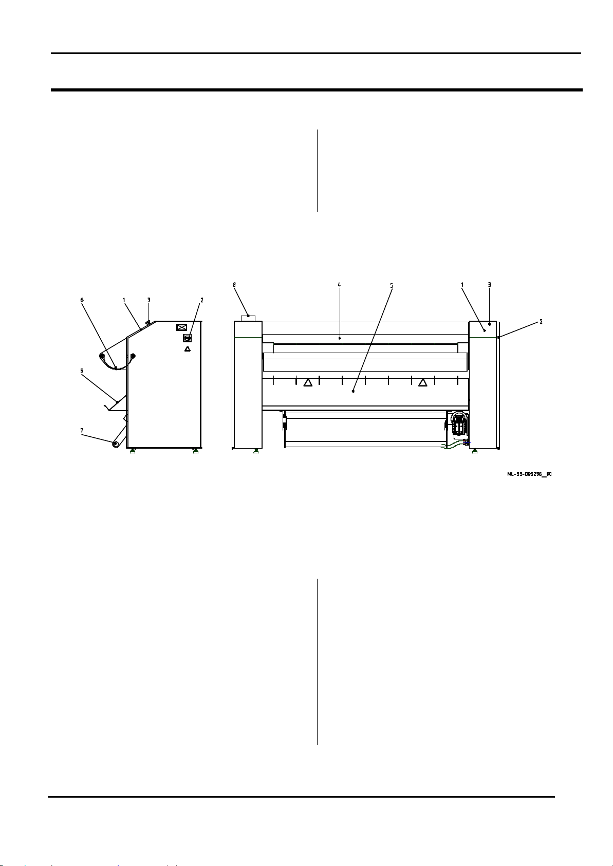
No 1: Operation panel
No 2: Main switch
No 3: Emergency stop
No 4: Input conveyor
No 5: Outlet tray
No 6: Tray for wet linen
No 7: Foot stop switch (option)
No 8: Exhaust pipe
Further information about the constructio
data" in the MANUAL.
MANUAL CI325.doc
V - 3.1. 7
Nr 1: Bedieningspaneel
Nr 2: Hoofdschakelaar
Nr 3: Noodstop knop
Nr 4: Invoer bed
Nr 5: Uitvoer plaat
Nr 6: Invoer zak nat linnen
Nr 7: Voet stop pedaal (optioneel)
Nr 8: Uitlaat pijp
gegevens” in de HANDLEIDING.
Page 8
CHAPTER I
It may involve risk to the operator to work
main switch has been locked in position
operator when taking the sheets direct
Er bestaat gevaar van verbranding als de
bedieningspersoon de lakens direkt bij
PRODUCT DESCRIPTION
IRONER
HOOFDSTUK I
PRODUCTBESCHRIJVING
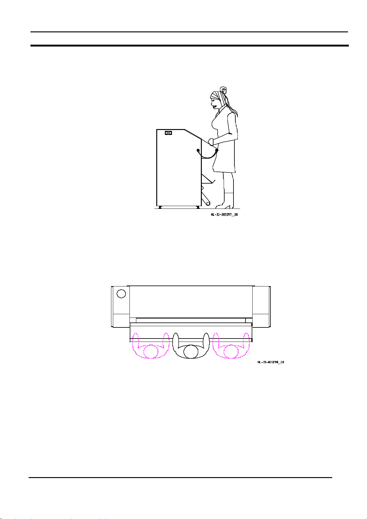
LAY-OUT AND WORKPLACES
1.4 Workplaces and noise level
The construction and appearance of the machine are
illustrated on the layout on the next page.
On the layout the operators’ workplaces during normal
operation are indicated by the human figures, which
are sketched in.
WARNING
on or under the machine. Work Stay in
these areas is only allowed for authorized
personnel, and only when the machine
has been stopped, cooled down and the
"0".
1.4 Werkposities en geluidsniveau
De opbouw en het aanzien van de machine zijn in de
lay-out op de volgende bladzijde geïllustreerd.
In de lay-out zijn de werkposities van de
bedieningspersonen tijdens normaal bedrijf in de vorm
van menselijke figuren aangeduid.
LAY-OUT EN WERKPOSITIES
WAARSCHUWING
De bedieningspersoon kan zich in gevaar
brengen als deze zich op of onder de
machine bevindt. Alleen bevoegd
personeel mag zich in deze gebieden
bevinden en alleen als de machine
gestopt is en de hoofd-schakelaar in
positie "0" vergrendeld is.
Normally the ironed pieces are coming into the outlet
tray after ironing ,where the operator can take them
without any danger.
WARNING
It may involve risk of burning to the
from the roll, deeper into the machine at
the outlet tray. Jams should always be
taken away by authorized personnel.
The sound pressure levels of the machine have been
measured at a height of 1.6 m at the indicated
workplaces of the operator. The values stated in dB
are as follows:
Workplace
The measurement has been performed on:14 -01-2002
Normaal komen de gemangelde stukken in de
uitvoertafel, waar ze zonder gevaar weggenomen
kunnen worden.
WAARSCHUWING
de rol, dieper in de machine bij de uitvoer
weghaalt. Vastlopers altijd door een
bevoegd persoon laten weghalen.
Het geluidsniveau van de machine is op een hoogte
van 1,6m bij de aangegeven werkposities van de
bedieningspersonen gemeten. De waarden, aangege ven in dB zijn als volgt:
60dB
De metingen zijn uitgevoerd op:14 -01-2002
Werkpositie
this machine
a similar machine
For more details see paragraph 1.5 ”technical data”
MANUAL CI325.doc
¨
ý
Voor meer datails zie hoofdstuk 1.5 ”technische
gegevens”
V - 3.1. 8
deze machine
een gelijksoortige machine
Page 9
CHAPTER I
PRODUCT DESCRIPTION
IRONER
HOOFDSTUK I
PRODUCTBESCHRIJVING
LAY-OUT AND WORKPLACES
LAY-OUT EN WERKPOSITIES
side view zijaanzicht
top view bovenaanzicht
MANUAL CI325.doc
V - 3.1. 9
Page 10
CHAPTER I
PRODUCT DESCRIPTION
IRONER
HOOFDSTUK I
PRODUCTBESCHRIJVING
WARRANTY AND SERVICE
GARANTIE- EN SERVICEBEPALINGEN
INSTRUCTIONS
1.5 Technical data
Machine No.
See front page
Machine type
Manufactured
See front page
1.5 Technische gegevens
Zie voorblad
CI 325
Zie voorblad
Machinenummer
Machinetype
Vervaardigd
Electrical connection
See front page
CI1650/325 CI2050/325
Roller Diameter
Length
Working width
Dimensions Height
Width
Depth (excl.
feeding bag)
Net weight (gas heated)
Net weight (electrical heated)
Electrical connection
323mm
1740mm
1600mm 2000mm
1140mm
2328mm
886 (650)mm
± 625 kg ±710 kg.
± 665 kg ±760 kg.
Zie voorblad
323mm
2140mm
1140mm
2728mm
886 (650)mm
Elektrische aansluiting
Rol Diameter
Lengte
Werkbreedte
Afmetingen Hoogte
Breedte
Diepte (excl. Invoer)
Nettogewicht (gas verwarmd)
Nettogewicht (electrisch
verwarmd)
Elektrische aansluiting
Electric 400V 3p + 0 50Hz
Electric 230V 3p + 0 50Hz
Gas 230V 1p + 0 50Hz
MANUAL CI325.doc
35A 35A
50A 65A
10A 10A
V - 3.1. 10
Elektrisch 400V 3f + 0 50Hz
Elektrisch 230V 3f + 0 50Hz
Gas 230V 1f + 0 50Hz
Page 11

CHAPTER I
PRODUCT DESCRIPTION
IRONER
HOOFDSTUK I
PRODUCTBESCHRIJVING
WARRANTY AND SERVICE
GARANTIE- EN SERVICEBEPALINGEN
INSTRUCTIONS
Other connections
CI1650/325 CI2050/325
Gas
Motor drive main roll
Motor ventilator
Adjustable speed
Airflow ventilator
Outlet (on top)
Use of power
Electrical heated
Gas heated
½” ½”
0.18kW 0.18kW
0.19kW 0.19kW
1.4->6 m/min. 1.4->6 m/min.
350m3/h 350m3/h
Ø 125 mm Ø 125 mm
CI1650/325 CI2050/325
18 kW 22.5 kW
28 kW 35 kW
Overige aansluitingen
Gas
Motor aandrijving rol
Motor ventilator
Variabele snelheid
Luchtstroomventilator
Afvoer (b oven)
Energie verbruik
Elektrisch verwarmd
Gasverwarmd
Electric consumption of gas heated
ironer
Electric consumption of electrical
ironer
Capacity linen (percentage of
moisture 50%)
Electrical
Gas
Ambient conditions:
Permitted max. ambient
temperature
Permitted max. relative moisture of
the atmosphere
Minimum size of linen:
Width
MANUAL CI325.doc
0.6 kW 0.6 kW
18.6 kW 23.1 kW
33 Kg/h
42.5 Kg/h
+40 °C
85 %
CI1650/325 CI2050/325
400mm 400mm
V - 3.1. 11
42 Kg/h
53.5 Kg/h
Elek. Verbruik gas verwarmde
machine.
Elek. Verbruik elektrisch verwarmde
machine.
Capaciteit wasgoed (percentage
luchtvochtigheid 50%)
Elektrisch
Gas
Omgevingsvoorwaarden:
Max. toelaatbare
omgevingstemperatuur
Max. toelaatbare luchtvochtigheid
Minimumafmeting wasgoed:
Breedte
Page 12

CHAPTER I
PRODUCT DESCRIPTION
IRONER
HOOFDSTUK I
PRODUCTBESCHRIJVING
WARRANTY AND SERVICE
GARANTIE- EN SERVICEBEPALINGEN
INSTRUCTIONS
Sound level measurement
Measuring points
The measuring points (see layout, paragraph 1.4) are
Measuring method
The measuring result is an average of a measure-
Measuring conditions
During the measurements, the machine will be
Measuring equipment
Meting geluidsniveau
Meetpunten
De meetpunten (zie layout paragraaf 1.4 ) zijn als
Meetmethode
Het meetresultaat is het gemiddelde van een
Meetvoorwaarden
Tijdens de metingen is de machine voorzien van
Meetapparatuur
The measurements are carried out with a noise meter
De metingen worden met een geluidmeter uitgevoerd,
MANUAL CI325.doc
V - 3.1. 12
Page 13
CHAPTER I
PRODUCT DESCRIPTION
IRONER
HOOFDSTUK I
PRODUCTBESCHRIJVING
WARRANTY AND SERVICE
GARANTIE- EN SERVICEBEPALINGEN
INSTRUCTIONS
Conversion table
Length:
1 m = 1,000 mm = 3.2808 ft = 39.3701 in
Weight:
1 kg = 1,000 g = 2.2046 lb
Area:
1 m2 = 10.7639 ft2 = 1.550 . 103 in2
Volume:
1 m3 = 1,000 l = 35.3145 ft3 = 60.976 . 103 in3
Temperature:
°C = 0.556 . (°F - 32)
(0 °C = 32.0 °F)
Omrekeningstabel
Lengte:
1 m = 1,000 mm = 3.2808 ft = 39.3701 in
Gewicht:
1 kg = 1,000 g = 2.2046 lb
Oppervlakte:
1 m2 = 10.7639 ft2 = 1.550 . 103 in2
Volume:
1 m3 = 1,000 l = 35.3145 ft3 = 60.976 . 103 in3
Temperatuur:
°C = 0.556 . (°F - 32)
(0 °C = 32.0 °F)
Force:
1 N = 0.2248 lbf
Pressure:
1 Pa = 0.145 . 10-3 psi
1 bar = 14.50 psi
Tension, mechanical:
1 N/mm2 = 106 Pa = 145.0 lbf/in2
Energy, mechanical:
1 J = 947.8 . 10-6 Btu
Energy, electrical:
1 kWh = 3.412 . 103 Btu
Effect:
1 kW = 3413 Btu/h = 1.341 hp
Kracht:
1 N = 0.2248 lbf
Druk:
1 Pa = 0.145 . 10-3 ps i
1 bar = 14.50 psi
Spanning, mechanisch:
1 N/mm2 = 106 Pa = 145.0 lbf/in2
Energie, mechanisch:
1 J = 947.8 . 10-6 Btu
Energie, elektrisch:
1 kWh = 3.412 . 103 Btu
Effect:
1 kW = 3413 Btu/h = 1.341 hp
Momentum:
1 Nm = 737.1 . 10-3 lb-ft
MANUAL CI325.doc
V - 3.1. 13
Moment:
1 Nm = 737.1 . 10-3 lb-ft
Page 14

CHAPTER I
The manufacturer undertakes to replace defective
parts resulting from faulty design, materials or
nths
from contractual delivery time, or max. 2,500
operating hours. The warranty is only valid if the
product is correctly installed and maintained in
accordance with the manufacturer's instruction and
common practice. No warranty claim can be made
esult of inappropriate operation, improper use,
De fabrikant is verplicht, gedurende 12 maanden
vanaf de contractuele leverdatum of maximaal 2.500
werkuren, defecte onderdelen ontstaan door
ikagefouten
mage that is due to insufficient maintenance,
changes or repair made without the written consent of
ue to war,
strike, lockout, and other force majeure or political
conditions, which the manufacturer cannot control.
The same applies to damage to products, which are
not supplied by the manufacturer or a construction
is niet van toepassing op beschadigingen
die ontstaan zijn door onvoldoende of verkeerd
onderhoud, door veranderingen/ reparaties aan de
machine waarvan de fabrikant niet schriftelijk op de
hoogte is gesteld, normale slijtage of defecten die te
n aan oorlog, werkstaking, uitsluiting en
overige force majeure of politieke situaties waarop de
fabrikant geen invloed heeft. Hetzelfde is van
afkomstig zijn van de fabrikant alsmede op producten
Wearing parts such as transport belts, drive belts or
Faulty parts will be replaced by the manufacturer
faulty components. Transport
costs to the manufacturer and back to the buyer,
transport insurance and installation costs are for the
De fabrikant zal defecte onderdelen na ontvangst van
kosten naar de fabrikant en terug naar de koper
alsmede de transportverzekering zijn op kosten van
PRODUCT DESCRIPTION
IRONER
HOOFDSTUK I
PRODUCTBESCHRIJVING
WARRANTY AND SERVICE
GARANTIE- EN SERVICEBEPALINGEN
INSTRUCTIONS
1.6 Warranty and service
1.6 Garantie- en servicebepalingen
instructions
workmanship for a period not exceeding 12 mo
constructiefouten, materiaalfouten of fabr
te vervangen. Deze garantie is alleen geldig als het
product correct geïnstalleerd is en overeenkomstig
de instructies van de fabrikant en de gebruikelijke
toepassing onderhouden is. Er kan geen aanspraak
as a r
and use of force.
The manufacturer's warranty does not include da-
op de garantie gemaakt worden bij onjuiste
bediening, onjuist gebruik en bij gebruik van geweld.
De garantie
the manufacturer, normal wear or defects d
ordered by the buyer.
similar are not included in the warranty.
The manufacturer is not liable for production losses
due to machine malfunctions.
upon receipt of the
buyer's account.
wijten zij
toepassing op beschadigingen aan producten die niet
die op verzoek van de klant veranderd zijn.
Onderdelen die aan slijtage onderhevig zijn zoals
singels, aandrijfriemen e.d. vallen buiten de garantie.
De fabrikant is niet aansprakelijk voor productieverlies
ten gevolge van machinestoringen.
deze onderdelen vervangen. De vracht - en montage-
de koper.
MANUAL CI325.doc
V - 3.1. 14
Page 15

CHAPTER III
OPERATION
IRONER
HOOFDSTUK I
PRODUCTBESCHRIJVING
TABLES OF CONTENTS
Paragraph
Operating devices and their
position
Starting the machine III-2
Functions III-3
Trouble shooting III-4
III-1
Bedieningselementen en hun
posities
Starten van de machine III-2
Functies III-3
Storingzoeken III-4
INHOUDSOPGAVE
Paragraaf
III-1
MANUAL CI325.doc
V - 3.1. 15
Page 16
CHAPTER III
OPERATION
IRONER
HOOFDSTUK III
BEDIENING
STARTING THE MACHINE
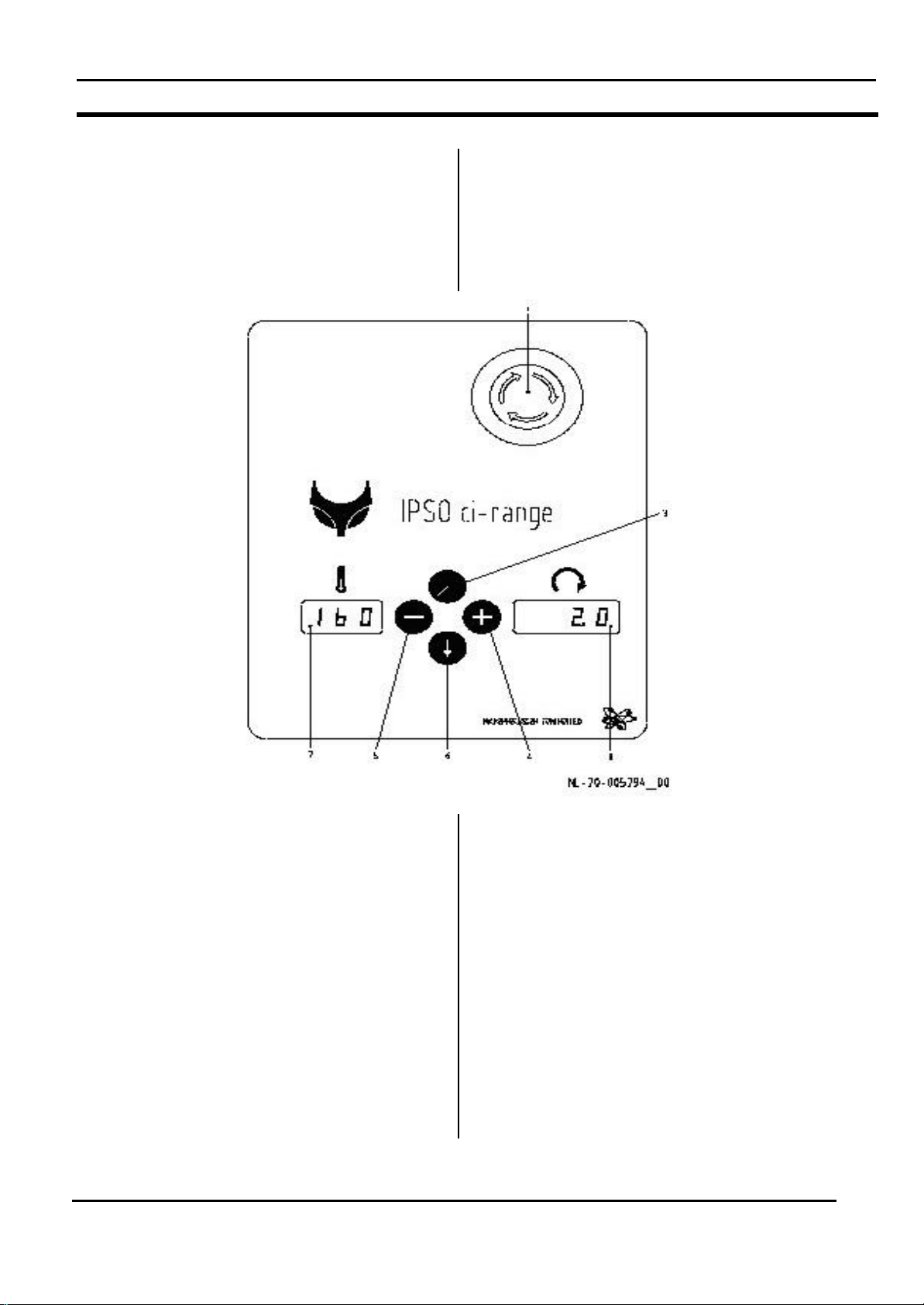
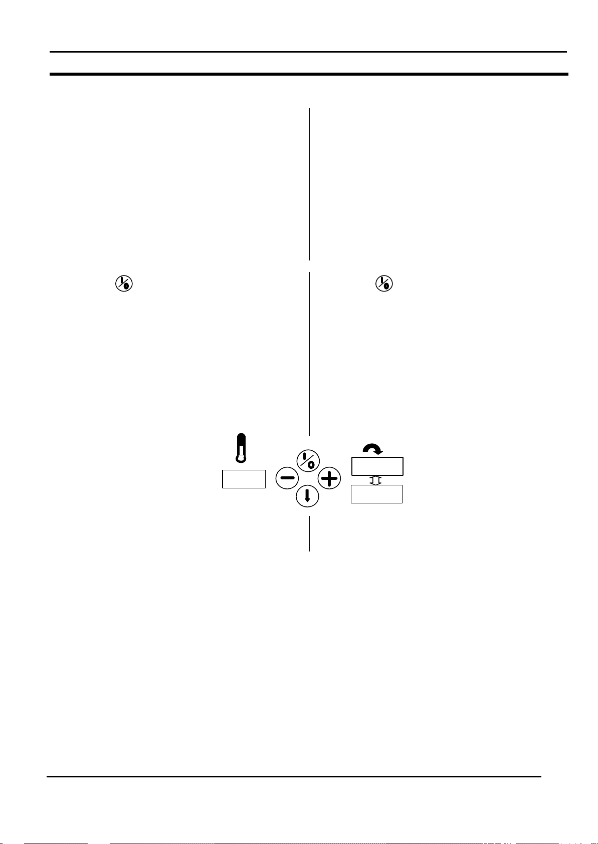
3.1 Operating devices and their
position
The machine is equipped with the following
operating devices:
3.1 Bedieningselementen en hun
posities
De machine is voorzien van de volgende bedienings inrichtingen:
STARTEN VAN DE MACHINE
No. 1: Emergency stop button
No. 3: Start/stop button
No. 4: “+” Button
No. 5: “-“ Button
No. 6: Return button
No. 7: Left display (temperature)
No. 8: Right display (speed)
When the power is switched to the machine by the
main switch, then “IPSO” and the version of the
program will appear for 5 seconds.
Then the left display will give the actual
temperature (in °C or °F) and the right display will
give the actual speed (in M/min).
MANUAL CI325.doc
Nr. 1: Noodstop schakelaar
Nr. 3: Start-/stopknop
Nr. 4: ”+” Toets
Nr. 5: ”-” Toets
Nr. 6: Terugkeertoets
Nr. 7: Linker display (temperatuur)
Nr. 8: Rechter display (snelheid)
Als de voedingsspanning d.m.v. van de
hoofdschakelaar op de machine ingeschakeld wordt,
verschijnt gedurende 5 seconden ”IPSO” en de
programma-versie.
Het linker display toont dan de huidige temperatuur (in
°C of °F) en het rechter display toont the huidige
snelheid (in M/min.)
V - 3.1. 16
Page 17
CHAPTER III
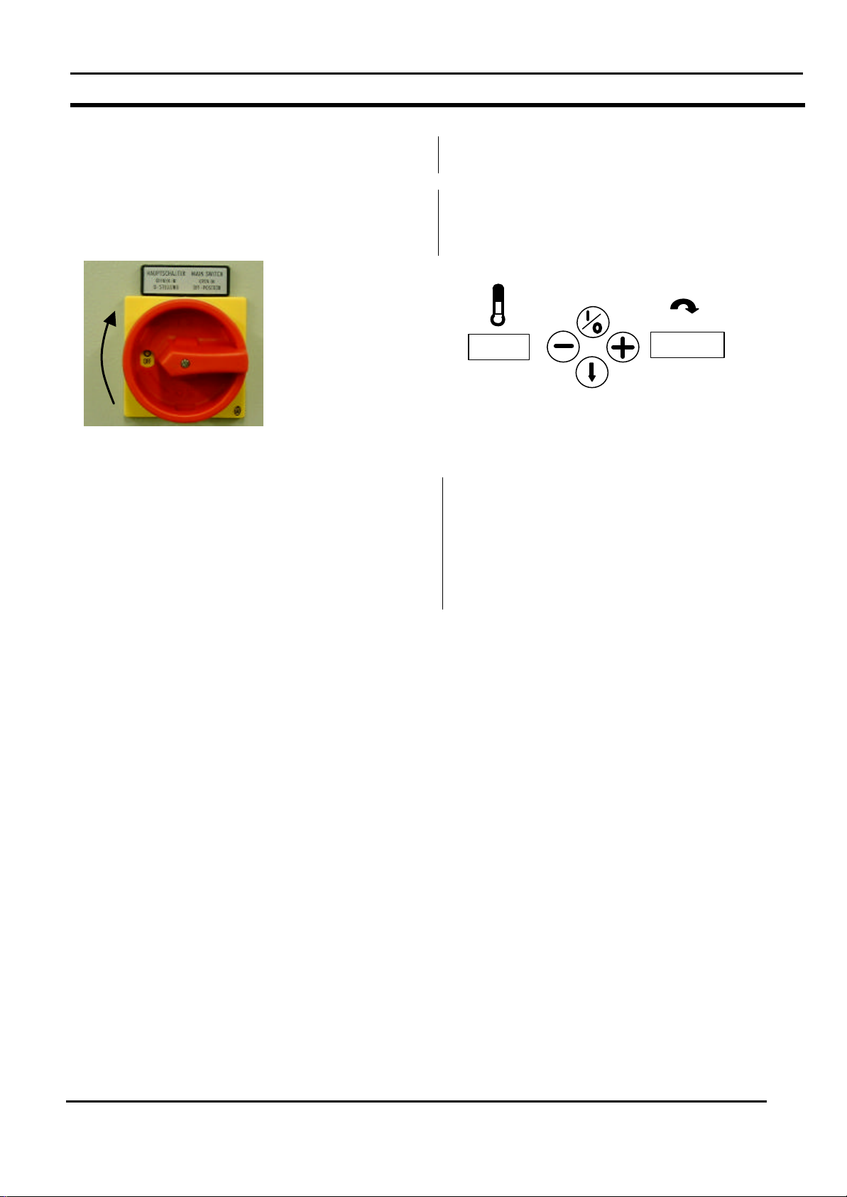
After switching the power to the machine by means of
the main switch (see picture below), the display will
1.4
20.
OPERATION
IRONER
HOOFDSTUK III
BEDIENING
STARTING THE MACHINE
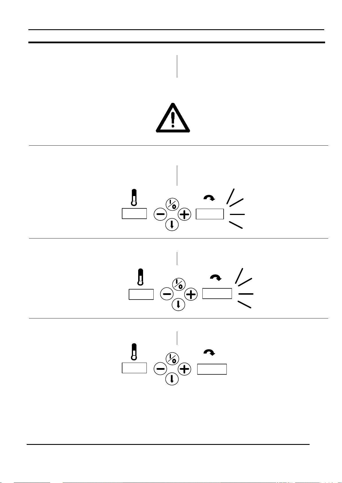
3.2 Starting the machine
show after 5 seconds:
The ironer starts running and the heating is activated.
The small dot in the left display shows that the heating
power is activated.
If the small dot is blinking only 1 set of element is
activated (only electrical heated ironers).
3.2 Starten van de machine
Na het inschakelen van de voedingsspanning door
middel van de hoofdschakelaar (zie plaatje
hieronder), verschijnt na 5 seconden op het display:
De mangel gaat draaien en de verwarming wordt
geactiveerd.
Een punt op het linker display toont dat de verwarming
geactiveerd is.
Als de punt knippert, is slechts 1 groep van elementen
geactiveerd (alleen bij elektrisch verwarmde mangels).
STARTEN VAN DE MACHINE
MANUAL CI325.doc
V - 3.1. 17
Page 18

CHAPTER III
OPERATION
IRONER
HOOFDSTUK III
BEDIENING
STARTING THE MACHINE
STARTEN VAN DE MACHINE
MANUAL CI325.doc
V - 3.1. 18
Page 19
CHAPTER III
button. Once the setting is done, press the return
foot
20.
OPERATION
IRONER
HOOFDSTUK III
BEDIENING
FUNCTIONS
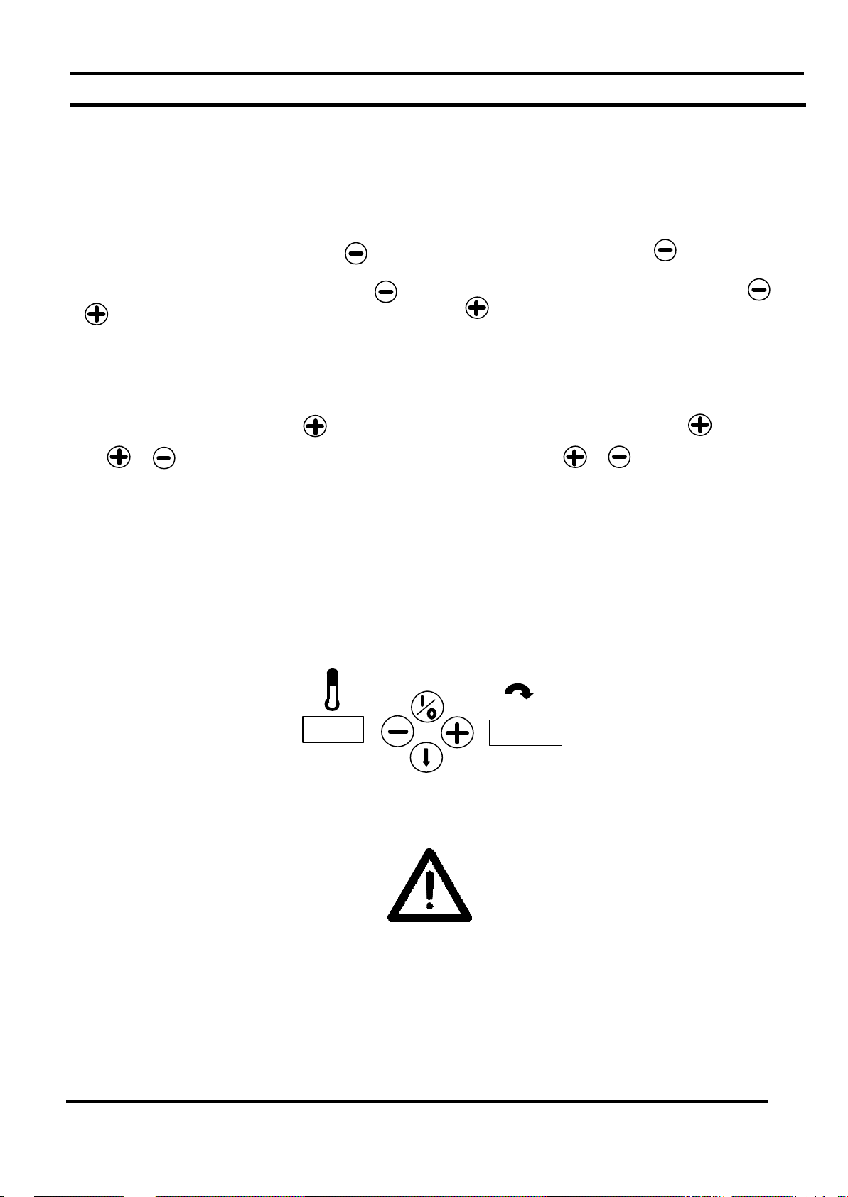
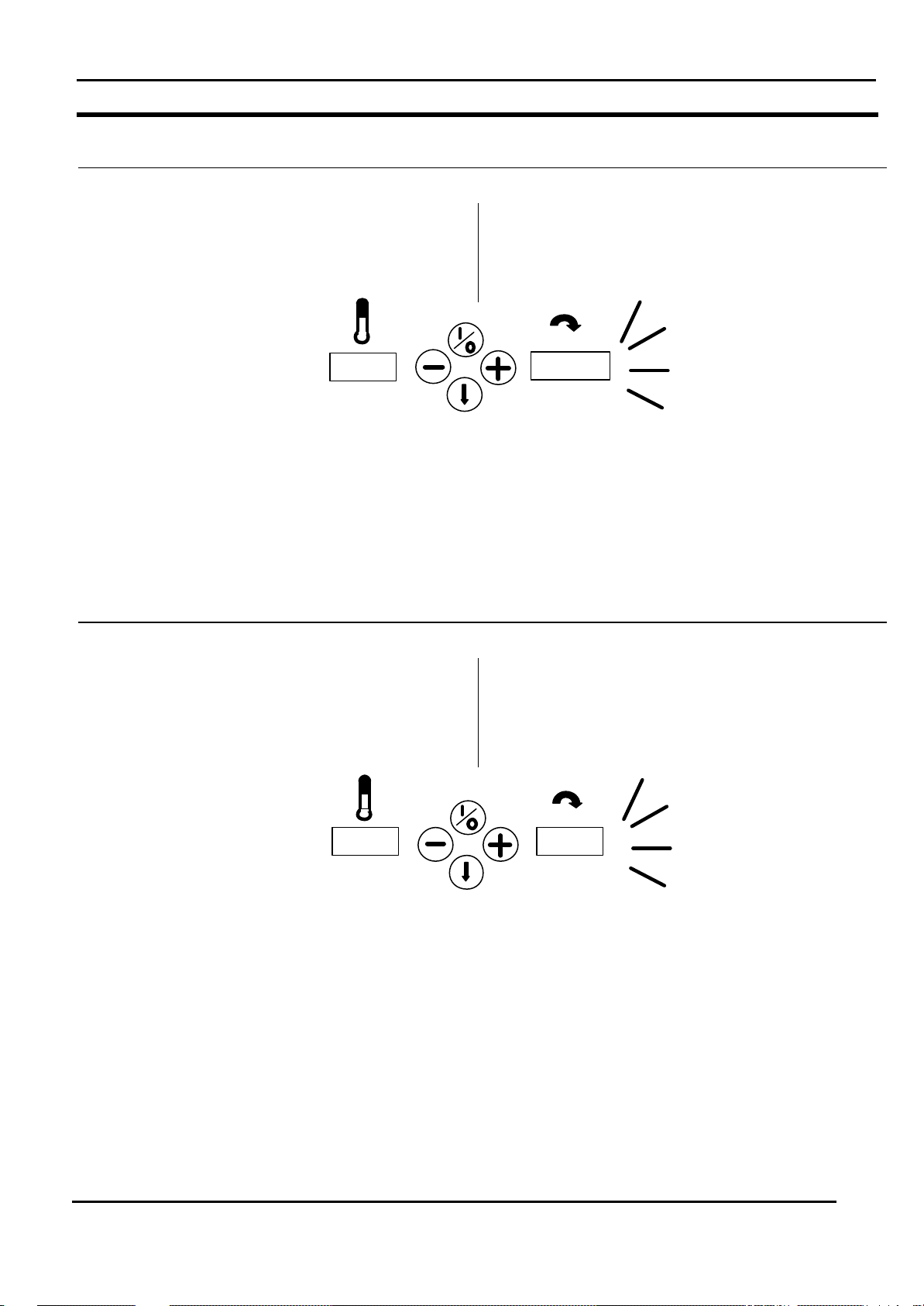
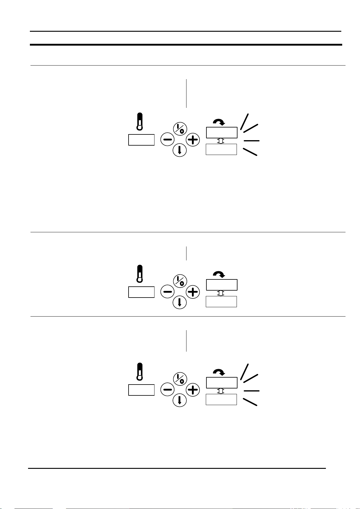
3.3 Functions
Setting of the iron temperature
The left display is giving the previous setting of the
temperature in a blinking mode when the button
is pressed.
Now the setting is changeable by pushing the or
button to confirm.
Setting of the ironing speed
The right display is giving the previous setting of the
speed in a blinking mode when the button is
pressed. Now the setting is changeable by pushing
the or button. Once the setting is done,
press the return button to confirm.
3.3 Functies
Instellen van de strijktemperatuur
Het linker display toont knipperend de vorige instelling
van de temperatuur wanneer de toets ingedrukt
wordt.
Nu kan de instelling gewijzigd worden d.m.v.de
of toets. Zodra de instelling gemaak t is, moet dit
met de terugkeertoets bevestigd worden.
Instellen van de strijksnelheid
Het rechter display toont knipperend de vorige
instelling van de snelheid wanneer de toets
ingedrukt wordt. Nu kan de instelling gewijzigd
worden d.m.v. de of toets. Zodra de instelling gemaakt is, moet dit met de terugkeertoets
bevestigd worden.
FUNCTIES
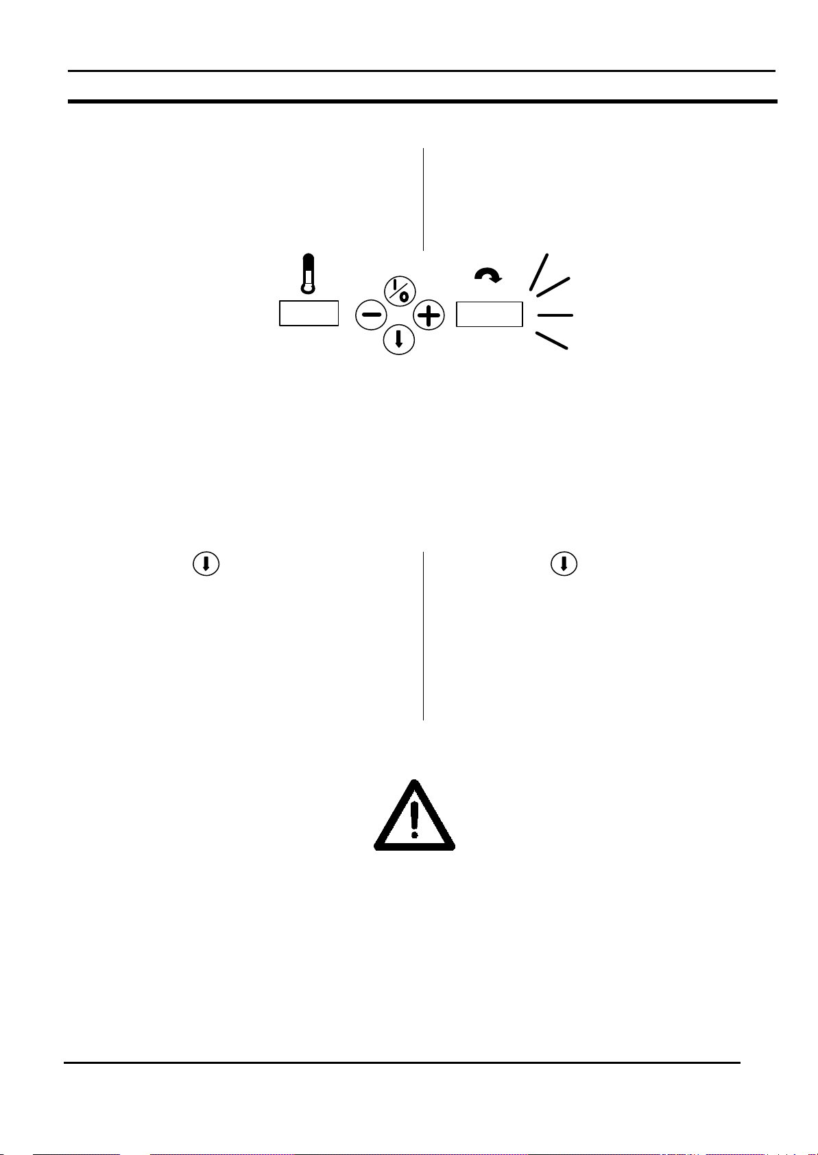
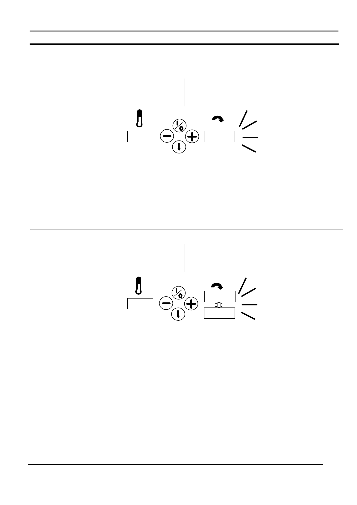
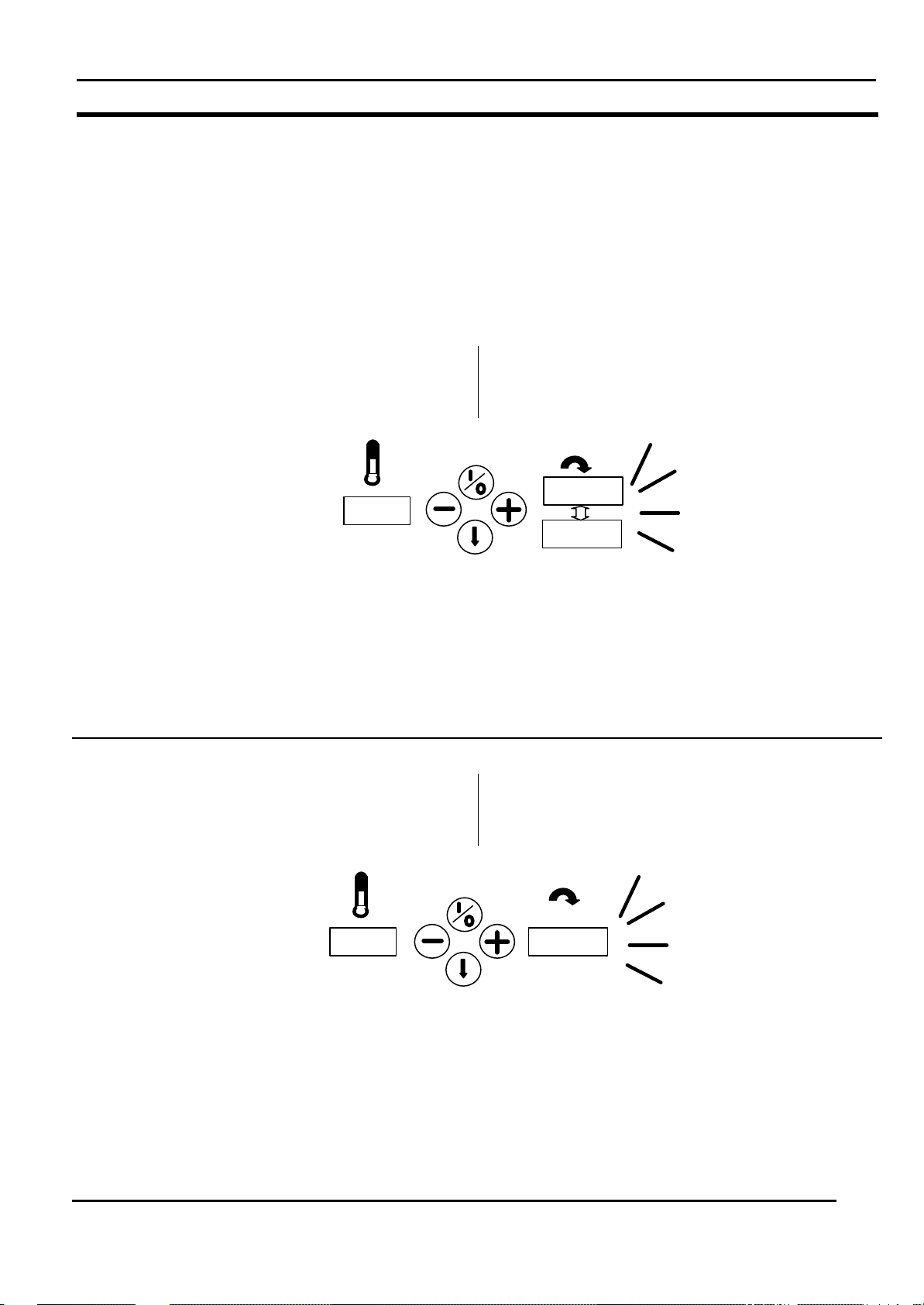
Pedal
The pedal can be used to spread out the linen.
The feeding and ironing belts stop turning while this
pedal is being stepped on and the display will show:
WARNING
Do not use this pedal more and longer
than necessary to avoid damage of the
linen by overheating. The machine gives
a acoustical signal after some seconds
to warn.
Voetpedaal
De voetpedaal kan gebruikt worden om het linnen
eenvoudig te kunnen uitspreiden.
De invoer - en mangelbanden stoppen met draaien
zolang op deze pedaal wordt getrapt. Op het display
verschijnt dan:
WAARSCHUWING
Gebruik deze pedaal niet meer en langer
dan noodzakelijk teneinde beschadigingen aan het wasgoed te voorkomen. De
machine geeft na enige seconden een
akoestisch waarschuwingssignaal.
MANUAL CI325.doc
V - 3.1. 19
Page 20
CHAPTER III
Take the linen away and reset the emergency
20.
EMEr
OPERATION
IRONER
HOOFDSTUK III
BEDIENING
FUNCTIONS
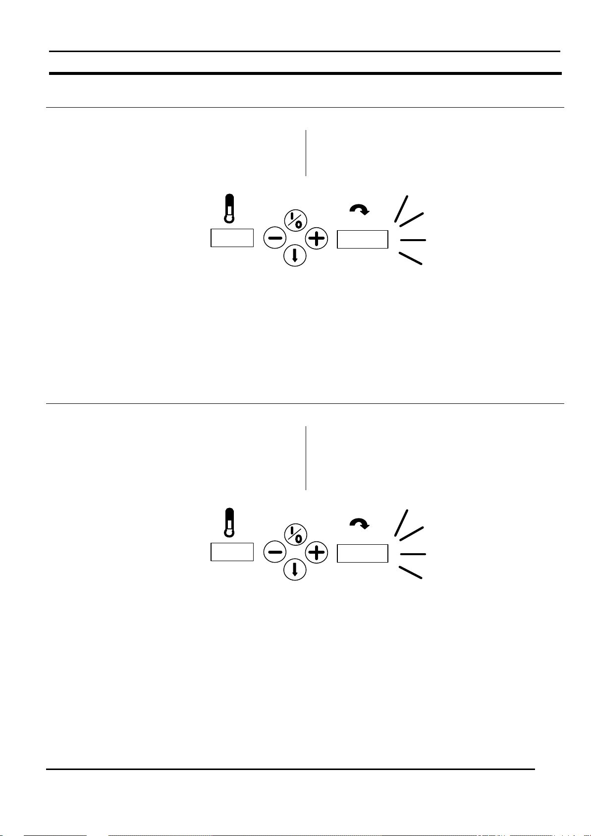
Finger protection panel
For safety reasons the feeding and ironing belts stop
turning if the finger protection panel is pushed
backwards. The buzzer is activated and on the
display will appear:
IMPORTANT
This panel may also be pushed back due to
accumulation or multiple folding of linen,as a
result of which the machine also stops and
the same warning is coming on the display.
circuit and start the machine again.
G
Vingerbeveiligingspaneel
Voor veiligheidsredenen stoppen de invoer- en
strijkbanden wanneer het vingerbeveiligingspaneel
naar achteren gedrukt wordt. De zoemer wordt
geactiveerd en op het display verschijnt dan:
BELANGRIJK
Dit paneel mag ook naar achteren geduwd
worden bij opeenhoping van veel vuldig
gevouwen wasgoed waardoor de machine
stopt en dezelfde waarschuwing verschijnt
op het display. Verwijder het wasgoed en
reset het noodstopcircuit en herstart de
machine.
FUNCTIES
Return Button
In case a piece is fixated inside the ironer, It is
possible to let the feeding belts and the main roll with
the belts turn backwards by pressing the return
button continuously. It is necessary to pull the linen
tightly backwards when doing so. After having
released this button, press the start button again,
otherwise the ironing process will be ended.
WARNING
Do not use this button when the linen has
already completely disappeared from the
feeding belts into the ironer. This could
cause a jam inside the ironer and damage
the linen and or the ironer.
Terugkeertoets
Wanneer een wasstuk binnenin de mangel vastzit,
dan is het mogelijk de invoerbanden en de hoofdrol
met de singles terug te laten draaien door de
terugkeertoets continu ingedrukt te houden. Bij
het terughalen van het wasgoed is het noodzakelijk
dat het wasgoed strak teruggetrokken wordt. Na het
loslaten van de toets, moet weer op de startknop
gedrukt worden, anders stopt het strijkproces.
WAARSCHUWING
Gebruik deze toets nooit als het wasgoed
reeds volledig van de invoerbanden
verdwenen is en in de mangel zit. Dit kan
vastlopers binnenin de mangel veroorzaken
wat beschadigingen aan het wasgoed en
mangel tot gevolg kan hebben.
MANUAL CI325.doc
V - 3.1. 20
Page 21
CHAPTER III
20.
2.2
Cool
OPERATION
IRONER
HOOFDSTUK III
BEDIENING
FUNCTIONS
Ironing
Now it is possible to start ironing as the temperature
is high enough.
Put the linen as flat as possible on the ironing in
feed belts in order to avoid creasing.
The linen will be carried on into the ironer by the
feeding belts.
Always spread open the linen by hand as flat as
possible and make sure that it does not get stuck
anywhere.
Ending
The ironing process is stopped by pressing the start
button.
The heating is switched off. However, in order not to
get overheated, the feeding and ironing belts, as well
as the fan keep running until the cool-down
temperature (see technical data setting mode
Manu:”Cool”) is reached.
Strijken
Mits de temperatuur hoog genoeg is kan met het
strijkproces gestart worden.
Leg het wasgoed zo vlak mogelijk op de
mangelinvoerbanden teneinde plooien te voorkomen.
Het wasgoed wordt verder in de mangel
getransporteerd d. m.v. van de invoerbanden.
Strijk het wasgoed altijd handmatig glad en zorg
ervoor dat het nergens vast kan lopen.
Stoppen
Het strijkproces wordt gestopt door het indrukken van
de startknop.
De verwarming wordt uitgeschakeld. Echter, om
oververhitting te voorkomen, zullen de invoer - en
mangelbanden alsmede de ventilator nog
doordraaien tot de afkoeltemperatuur (zie technische
gegevens instelmode Manu:”Cool”) bereikt is.
FUNCTIES
The speed and “Cool” are alternately displayed on
the right display during this cool-down period.
After the cool down temperature is reached the drive
and the ventilator are switched off.
De snelheid en “Cool” verschijnen om en om op het
rechter display tijdens deze afkoelperiode.
Nadat de afkoeltemperatuur bereikt is, worden de
aandrijving en de ventilator uitgeschakeld.
MANUAL CI325.doc
V - 3.1. 21
Page 22
CHAPTER III
20 . ENEr
hand
tst
foot
130
OPERATION
IRONER
HOOFDSTUK III
BEDIENING
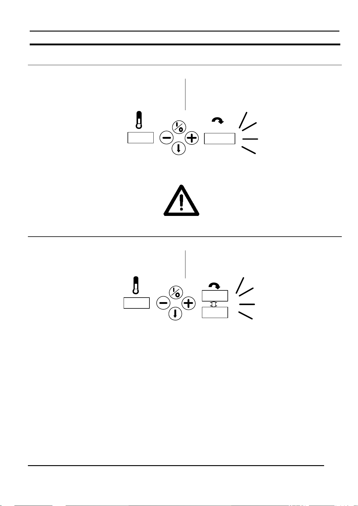
TROUBLE SHOOTING
3.4 Failure and information signals
3.4 Foutmeldingen en display-
PROBLEEMZOEKEN
informatie
WARNING
If the procedure described here does not
rectify the operational failure, the technical personnel of the laundry should be
called in.
Emergency circuit activated by emergency stop or
hand protection.
Noodstopcircuit geactiveerd door noodstop of
handbeveiliging.
WAARSCHUWING
Als de hier beschreven procedure de
storing niet opheft, moet het technisch
personeel van de wasserij inge schakeld
worden.
Test of hand protection has to be made.
The foot pedal is pressed
Handbeveiligingstest moet uitgevoerd worden.
Het voetpedaal is ingeduwd.
MANUAL CI325.doc
V - 3.1. 22
Page 23
CHAPTER III
no heat
195
hEAt
OPERATION
IRONER
HOOFDSTUK III
BEDIENING
TROUBLE SHOOTING
There is a failure in the gas control by gas heated
ironer.
There is a failure in the relays for the heating
elements.
IMPORTANT
When this signal is coming an engineer has
to open the side frame to reset the gas
control in case of a gas heated ironer.
Er is een fout in de gasbesturing (bij gasverwarmde
mangels).
Er is een fout in de relais voor de
verwarmingselementen.
BELANGRIJK
Als dit signaal komt, moet in geval van een
gasverwarmde mangel een servicemonteur
het zijframe openen om de gasbesturing te
resetten.
PROBLEEMZOEKEN
G
There is an overheat problem (more than 190 °
detected)
There is a short cut in the temperature sensor.
There is an broken wire in the temperature sensor.
IMPORTANT
When the belts and roll are not running and
this failure is active with a fast acoustic
signal the roll had to be started to prevent
burned pieces inside the ironer.
Er is oververhitting (meer dan 190° gedetecteerd)
Er is kortsluiting in de temperatuursensor.
Een draad in de temperatuursensor is kapot.
BELANGRIJK
Wanneer de banden en de rol niet draaien
en deze fout is actief samen met een snel
akoestisch signaal, dan moet de rol gestart
G
worden teneinde verbrande onderdelen in
de mangel te voorkomen.
MANUAL CI325.doc
V - 3.1. 23
Page 24
CHAPTER III
hot
120
130
hot
ENEr
OPERATION
IRONER
HOOFDSTUK III
BEDIENING
TROUBLE SHOOTING
The machine is stopped by the stop button and the
temperature is higher than the cool down
temperature.
IMPORTANT
When this sign is active the roll had to be
started as soon as possible to prevent
burned pieces inside the ironer.
De machine is d.m.v. de stopknop gestopt en de
temperatuur is hoger dan de afkoeltemperatuur.
BELANGRIJK
Als deze foutmelding actief is, moet de rol
zo snel mogelijk gestart worden ter
voorkoming dat onderdelen in man gel
verbranden.
PROBLEEMZOEKEN
G
Emergency switch is pressed or hand protection is
pressed at a moment the machine is hotter than the
cool down temperature
IMPORTANT
The machine has to started up as soon as
a save situation is reached. There is a
possibility that linen in the ironer will be
damaged by burning if the machine is not
quick started up again.
De noodstop of de handbeveiliging is ingedrukt op het
moment dat de machine heter is dan de
afkoeltemperatuur.
BELANGRIJK
De machine moet opgestart worden zodra
er een veilige situatie bestaat. Er is een
mogelijkheid dat wasgoed door verbranding
G
beschadigd wordt als de machine niet snel
opnieuw opgestart wordt.
MANUAL CI325.doc
V - 3.1. 24
Page 25
CHAPTER III
195
heat
EMer
130
2.2
Cool
195
heat
Foot
OPERATION
IRONER
HOOFDSTUK III
BEDIENING
TROUBLE SHOOTING
Emergency switch is pressed or hand protection is
pressed at a moment the machine is in overheat
situation. (temperature more than 190 °C).
IMPORTANT
The machine has to started up as soon as
a save situation is reached. There is a
possibility that linen in the ironer will be
damaged by burning if the machine is not
quick started up again.
De noodstop of de handbeveiliging is ingedrukt op het
moment dat de machine oververhit is. (temperatuur
hoger dan 190°C).
BELANGRIJK
De machine moet opgestart worden zodra
er een veilige situatie bestaat. Er is een
mogelijkheid dat wasgoed door verbranding
G
beschadigd wordt als de machine niet snel
opnieuw opgestart wordt.
PROBLEEMZOEKEN
Cool down situation
The foot pedal is pressed and there is an overheat
situation.
Afkoelfase
Het voetpedaal is ingetrapt en de mangel is
oververhit.
MANUAL CI325.doc
V - 3.1. 25
Page 26
CHAPTER III
130
hot
foot
air
no
OPERATION
IRONER
HOOFDSTUK III
BEDIENING
TROUBLE SHOOTING
IMPORTANT
The foot pedal has to be released as soon
as possible. There is a possibility that linen
in the ironer or the belts of the ironer will be
damaged by burning if the machine is not
quick started up again.
The foot pedal is pressed longer than 30 seconds
and the machine temperature is higher than the cool
down temperature.
G
Het voetpeda al is langer dan 30 seconden ingetrapt
en de machinetemperatuur is hoger dan de
afkoeltemperatuur.
BELANGRIJK
Het voetpedaal moet zo snel mogelijk
losgelaten worden. Er is een mogelijkheid
dat wasgoed in de mangel of de
mangelbanden door verbranding beschadigd worden als de machine niet snel
opnieuw opgestart wordt.
PROBLEEMZOEKEN
IMPORTANT
The foot pedal has to be released as soon
as possible to prevent that linen in the ironer
will be damaged by burning.
The pressure switch is not activated (due to dirty filter
or ventilator is not running or to much counter
pressure in exhaust pipe.)
IMPORTANT
BELANGRIJK
Het voetpedaal moet zo snel mogelijk
losgelaten worden om te voorkomen dat
wasgoed in de mangel door verbranding
beschadigd wordt.
G
De drukschakelaar is niet geactiveerd (t.g.v. vuile
filter of ventilator niet loopt of te veel tegendruk in de
afzuigbuis).
BELANGRIJK
The filter should be cleaned inside the frame
at the left side.
MANUAL CI325.doc
G
V - 3.1. 26
Het filter binnenin het frame aan de
linkerzijde moet schoongemaakt worden.
Page 27
CHAPTER III
air
cnt
Spee
no
OPERATION
IRONER
HOOFDSTUK III
BEDIENING
TROUBLE SHOOTING
The pressure switch is activated when the ventilator
is not active. (pressure switch is damaged or
bypassed).
IMPORTANT
An engineer must check the working of the
switch and replace it in case of malfunction
of the switch.
De drukschakelaar is geactiveerd als de ventilator
niet actief is. (drukschakelaar is defect of
gebypassed).
BELANGRIJK
schakelaar controleren en deze vervangen
indien nodig.
PROBLEEMZOEKEN
The speed sensor is not giving signals and the motor
is activated (speed sensor is damaged or motor is not
running).
IMPORTANT
The foot pedal has to be released as soon
as pos sible to prevent that linen in the ironer
will be damaged by burning.
G
De snelheidsensor geeft geen signalen en de motor is
geactiveerd (snelheidsensor is kapot of the motor
loopt niet).
BELANGRIJK
Het voetpedaal moet zo snel mogelijk
losgelaten worden om te voorkomen dat
wasgoed in de mangel door verbranding
beschadigd wordt.
G
MANUAL CI325.doc
V - 3.1. 27
Page 28
CHAPTER III
hEAt
cnt
hot
rest
106
OPERATION
IRONER
HOOFDSTUK III
BEDIENING
TROUBLE SHOOTING
The heating elements are switched off but the relay
stays on (contacts of the relay are burned together).
WARNING
The relays had to be changed out to
prevent overheating of the ironer and
damage to linen and ironer.
De verwarmingselementen zijn uitgeschakeld maar
het relais blijft aan (contacten van de relais zijn
verbrand).
WAARSCHUWING
De relais moeten vervangen worden om te
voorkomen dat de mangel oververhit raakt
en het wasgoed en de mangel beschadigd
worden.
PROBLEEMZOEKEN
The machine is switched off under the cool down
temperature but the temperature of the roll has
become higher because of rest heat inside the ironer.
IMPORTANT
The machine should be started again and
switched directly to cool down again to finish
the cool down in a proper way.
MANUAL CI325.doc
G
V - 3.1. 28
De machine is onder de afkoeltemperatuur
uitgeschakeld maar de temperatuur van de rol is
hoger als gevolg van restwarmte binnen de mangel.
BELANGRIJK
De machine moet opnieuw opgestart worden
en direct weer op afkoelen gezet worden om
de afkoelfase goed af te ronden.
Page 29

CHAPTER IV
INITIAL SETUP OF THE
MACHINE
IRONER
HOOFDSTUK IV
INWERKSTELLING
TABLE OF CONTENTS
Paragraph
Transport and machine
fastening
IV-1
Veiligheid van de machine
tijdens transport
INHOUDSOPGAVE
Paragraaf
IV-1
Setting up the machine IV-2
Installatie van de machine IV-2
Basic checks IV-3
Testen en proefdraaien IV-3
MANUAL CI325.doc
V - 3.1. 29
Page 30

CHAPTER IV
INITIAL SETUP OF THE
MACHINE
IRONER
HOOFDSTUK IV
INWERKSTELLING
TRANSPORT AND MACHINE FASTENING
VEILIGHEID VAN DE MACHINE TIJDENS
TRANSPORT
4.1 Transport and machine fastening
4.1 Veiligheid van de machine tijdens
transport
The machine has been secured with bolts on a solid
wooden frame and has been safely packed in plastic
sheeting from the factory. Furthermore, bolted on de vices such as input bag and output tray are placed on
top of the machine.
WARNING/DANGER
During all transport and handling of the
machine there is a risk of the machine
tipping over or falling over onto
persons. In order to avoid accidents the
following should therefore be observed:
De machine wordt t.b.v. de veiligheid tijdens transport
in de fabriek op een houten frame vastgeschroefd en
zorgvuldig in plastic folie verpakt. Verder worden
demonteerbare delen of delen die uit de machine
steken zoals bijv. invoerzak en uitvoerplaat boven op
de machine gelegd.
WAARSCHUWING/GEVAAR
Tijdens het transport en de hantering
van de machine bestaat het risico dat de
machine omkantelt of op personen valt.
Om ongevallen te voorkomen moet op
het volgende gelet worden:
During transport and handling with a
fork-lift truck, the forks should be
situated proportional to the center of
gravity as shown on the next page and
on the packing of the machine.
Never use lifting- and hoisting material
with too small a lifting capacity. See
paragraph 1.5 concerning the weight of
the machine. The max. weight of the
machine including packing is stated on
the packing of the machine.
Never move the machine on inclined or
uneven surfaces.
Tijdens het transport en de hantering
met een vorkheftruck moeten de vorken
zich centrisch onder het zwaartepunt
bevinden, zoals op de volgende pagina
en op de verpakking van de machine
aangegeven is.
Gebruik nooit hef- en hijswerktuig dat
een te kleine hef-/hijscapaciteit heeft. Zie
paragraaf 1.5, gewicht van de machine.
Het maximale gewicht van de machine
inclusief verpakking is op de verpakking
van de machine genoteerd.
Verplaats de machine nooit op hellende
of hobbelige oppervlaktes.
MANUAL CI325.doc
V - 3.1. 30
Page 31

CHAPTER IV
INITIAL SETUP OF THE
MACHINE
IRONER
HOOFDSTUK IV
INWERKSTELLING
TRANSPORT AND MACHINE FASTENING
VEILIGHEID VAN DE MACHINE TIJDENS
TRANSPORT
IMPORTANT
We recommend you to let the wooden
frame remain bolted for the use of transport
with fork -lift truck, until the machine is near
the place of setting up.
MANUAL CI325.doc
G
V - 3.1. 31
BELANGRIJK
Als u de machine met een vorkheftruck
transporteert, raden wij u aan het houten
frame aan de machine vastgeschroefd te
laten, totdat de machine vlakbij de plaats is
waar deze opgesteld moeten worden.
Page 32

CHAPTER IV
INITIAL SETUP OF THE
MACHINE
IRONER
HOOFDSTUK IV
INWERKSTELLING
SETTING UP THE MACHINE
4.2 Setting up the machine
4.2.1 Preparation of the machine
ð
Inspect the machine by delivery on any
damage.
ð
The machine can be moved by a manual pallet
lifter.
ð
Remove the packing carefully and remove the
parts on top of the machine
ð
Place the machine on his final position. Keep
in mind that the sides of the machine have to
be free of any surroundings of at least 60 cm.
4.2 Installatie van de machine
4.2.1 Voorbereiding
ð
ð
ð
ð
INSTALLATIE VAN DE MACHINE
Inspecteer de machine bij de levering op
beschadigingen.
De machine kan met een palletheftruck
verplaatst worden.
Verwijder zorgvuldig de verpakking en haal de
onderdelen bovenop de machine weg.
Plaats de machine op de definitieve plaats.
Houd er rekening mee dat de zijkanten van de
machine tenminste 60cm van de muren
verwijderd zijn.
MANUAL CI325.doc
V - 3.1. 32
Page 33

CHAPTER IV
INITIAL SETUP OF THE
MACHINE
IRONER
HOOFDSTUK IV
INWERKSTELLING
SETTING UP THE MACHINE
4.2.2 Mechanical installation
Adjustment bolts
The machine has to be level. To check this use a
spirit level.
The machine can be levelled by adjusting the four
bolts under the machine. Loosen the lock nuts, adjust
the fo ur bolt so the machine is level and fasten the
lock nuts.
4.2.2 Mechanische installatie
Stelbouten
De machine moet waterpas staan. Gebruik een
luchtbelwaterpas om dit te controleren.
De machine kan waterpas gesteld worden door de
vier bouten onder de machine te verstellen. Draai de
borgmoeren los en verstel de vier bouten zodanig dat
de machine waterpas staat. Draai de borgmoeren
daarna weer aan.
INSTALLATIE VAN DE MACHINE
MANUAL CI325.doc
V - 3.1. 33
Page 34

CHAPTER IV
INITIAL SETUP OF THE
MACHINE
IRONER
HOOFDSTUK IV
INWERKSTELLING
SETTING UP THE MACHINE
Input bag
The bolts used for mounting the input bag are already
on the machine.
Remove the three bolts at each side. Push the two
tubes in the bag. Place the two end plates in the
tubes and lift the input bag into the machine. Start by
mounting the upper bolts at each side. After this place
the other four bolts and fasten them all six.
Invoerzak
De bouten die gebruikt worden voor het monteren
van de invoerzak zijn reeds aanwezig op de machine.
Verwijder de drie bouten aan elke zijde. Duw de twee
buizen in de zak. Plaats de twee eindplaten in de
buizen en til de invoerzak in de machine. Begin met
monteren van de bovenste bouten aan elke zijde.,
Plaats hierna de andere vier bouten en draai ze alle
zes vast.
INSTALLATIE VAN DE MACHINE
MANUAL CI325.doc
V - 3.1. 34
Page 35

CHAPTER IV
INITIAL SETUP OF THE
MACHINE
IRONER
HOOFDSTUK IV
INWERKSTELLING
SETTING UP THE MACHINE
Output tray
The bolts used for mounting the output tray are
already on the machine.
Remove the two bolts at each side. Place the two
side plates and fasten the four bolts.
Place the top plate on the side plates and guiding bar.
The plate is positioned by the guiding plates within
the machine. Place the four bolts and fasten them.
Uitvoerplaat
De bouten die gebruikt worden voor het monteren
van de uitvoerplaat zijn reeds aanwezig op de
machine.
Verwijder de twee bouten aan elke zijde. Plaats de
twee zijplaten en draai de vier bouten vast.
Plaats de bovenste plaat op de zijplaten en de
singelgeleiding. De singelgeleiding zorgt ervoor dat
de plaat op de goede positie in de machine zit. Plaats
de vier bouten en draai ze vast.
INSTALLATIE VAN DE MACHINE
Foot pedal (option)
The bolts used for mounting the foot pedal are
already on the machine in the bottom of the front
cross bar. Remove the two bolts at each side. Lift the
pedal in position and place the bolts and fasten them.
The switch used for the pedal is placed in the front
bar. The switch has to be mounted at the left side
plate of the pedal as shown in the figure below.
MANUAL CI325.doc
V - 3.1. 35
Voetpedaal (optie)
De bouten die gebruikt worden voor het monteren
van de voetpedaal zijn reeds aanwezig op de
machine, aan de onderkant van de voorste
dwarsbalk. Verwijder de twee bouten aan elke zijde.
Til de voetpedaal in de juiste positie, plaats de bouten
en draai ze aan.
De schakelaar die gebruikt wordt voor de voetpedaal
is geplaatst in de voorste balk. De schakelaar moet
bij de linkerplaat van de voetpedaal gemonteerd
worden.
Page 36

CHAPTER IV
INITIAL SETUP OF THE
MACHINE
IRONER
HOOFDSTUK IV
INWERKSTELLING
SETTING UP THE MACHINE
INSTALLATIE VAN DE MACHINE
MANUAL CI325.doc
V - 3.1. 36
Page 37

CHAPTER IV
dan 15m inclusief de
INITIAL SETUP OF THE
MACHINE
IRONER
HOOFDSTUK IV
INWERKSTELLING
SETTING UP THE MACHINE
Exhaust system
In order to ensure a satisfactory function of the
machine exhaust system, the subsequent pipe
system, which is installed in the laundry should as
minimum be dimensioned according to the following
guidelines. If the pressure loss in the piping system is
increased as a result of dimensioning faults, this will
cause a reduction of the exhaust and thus the
machine capacity.
In case of short distances between the ironer and the
outlet to the outside, i.e. less than 15m including
allowance for bends, the exhaust pipe can be made
as a channel with diameter 125 mm for all machine
types. In case of longer distances we recommend
you to use a larger pipe diameter. When judging the
exhaust channel, see the following tables that deal
with pressure loss and the dynamic pressure by
different pipe dim ensions and also deal with the
equivalent pipe lengths for different part elements in
an exhaust channel.
Dynamic pressure (Pd) in [Pa] and specific pressure
loss (∆p) in [Pa/m] dependent on volume flow (V) in
m3/h and pipe diameter (dia) in mm. S is the speed in
m/s.
Dia
V
M3/uur Pa Pa m/s Pa Pa m/s Pa Pa m/s Pa Pa m/s Pa Pa m/s
250 19 2 5,7
350 38 4 7,9 18 2 5,5 14 1 4,8
450 63 6 10,2 30 3 7,1 23 2 6,2 15 1 4,9 10 1 4,0
550 94 9 12,4 45 4 8,6 35 3 7,6 22 2 6,0 14 1 4,9
650 131 13 14,7 63 6 10,2 49 5 9,0 30 3 7,1 20 2 5,7
750 174 17 17,0 84 8 11,8 65 6 10,4 41 4 8,2 27 3 6,6
850 224 22 19,2 108 10 13,4 83 8 11,7 52 5 9,3 34 3 7,5
950 280 27 21,5 135 13 14,9 104 10 13,1 65 6 10,4 43 4 8,4
1050 342 33 23,8 165 16 16,5 127 12 14,5 79 8 11,5 52 5 9,3
Equivalent pipe length in m for selected single
resistances :
Right-angled corner : 13.4
90 degrees smooth bend R/D = 2 : 2.1
90 degrees angular bend R/D = 2 : 2.6
(three sections)
90 degrees angular bend R/D = 2 : 2.1
(five sections)
Pd ∆p S
125
150
Pd ∆p S
9 1 3,9 7 1 3,5
Afzuigsysteem
Om een toereikende werking van het afzuigsysteem
van de machine te garanderen, moet het
hiernavolgend buizensysteem, welke in de wasserij
geïnstalleerd is, van een zo klein mogelijke afmeting
zijn volgens de hieronder beschreven richtlijnen. Als
het drukverlies in het buizensysteem toeneemt als
gevolg van afmetingsfouten, zal dit een afname van
de afzuiging veroorzaken en dus ook de
machinecapaciteit.
In geval van korte afstanden tussen de mangel en de
afvoer naar buiten, d.w.z. korter
toeslag van bochten, kan de afzuigbuis als een
kanaal met een diameter van 125 mm voor alle
machinetypes gemaakt worden. In geval van langere
afstanden raden wij u aan een grotere pijpdiameter te
gebruiken. Bij kiezen van het afzuigk anaal, zie
onderstaand tabel dat de drukverlies en de
dynamische druk door verschillende pijpafmetingen
weergeeft en tevens de equivalente pijplengtes voor
verschillende onderdelen in een afzuigkanaal
berekent.
Dynamische druk (Pd) in [Pa] en specifiek drukverlies
(∆p) in [Pa/m] afhankelijk van volumestroom (V) in
m3/h en pijpdiameter (dia) in mm. S is de snelheid in
m/s.
160
Pd ∆p S
Equivalente pijp lengte in m voor geselecteerde
onderstaande enkele bocht weerstand.
Rechte hoek : 13.4
90 graden glad gebogen R/D = 2 : 2.1
90 graden in hoeken gebogen R/D = 2 : 2.6
(drie secties)
90 graden in hoeken gebogen R/D = 2 : 2.1
(vijf secties)
INSTALLATIE VAN DE MACHINE
180
Pd ∆p S
5 0 2,7
9 1 3,8
200
Pd ∆p S
3 0 2,2
6 1 3,1
MANUAL CI325.doc
V - 3.1. 37
Page 38

CHAPTER IV
INITIAL SETUP OF THE
MACHINE
IRONER
HOOFDSTUK IV
INWERKSTELLING
SETTING UP THE MACHINE
In general we recommend that the pressure loss in
the exhaust pipe is kept as low as possible. If more
machines are to be connected to the same exhaust
channel, it is necessary to contact a ventilating firm
that can advise you with regard to the correct
dimensioning of the exhaust channel.
The pressure loss in the exhaust channel can be
calculated in the following way :
Pchannel = Pd + Iength channel x ∆p
If Pchannel > 300 Pa we recommend to increase the
pipe dimension. For this purpose a prefabricated
transfer piece is to be used.
To avoid noise we advise to keep the maximum
velocity in the pipe under 12 m/sec
Over het algemeen raden wij u aan het drukverlies in
de afzuigbuis zo klein mogelijk te houden. Als
meerdere machines aan hetzelfde afzuigkanaal
aangesloten zijn, dan is het noodzakelijk een
ventilatiebedrijf in te schakelen dat u kan adviseren
over de juiste afmetingen van het afzuigkanaal.
Het drukverlies in het afzuigkanaal kan op de
volgende manier berekend worden:
Pkanaal = Pd + Iengte kanaal x ∆p
Als Pkanaal > 300 Pa, raden wij u aan de
buisafmeting te vergroten. Hiervoor wordt een
voorgefabriceerd overgangsstuk gebruikt.
Om extra geluid te vermijden wordt een maximum
luchtsnelheid van 12 m/sec geadviseerd.
INSTALLATIE VAN DE MACHINE
MANUAL CI325.doc
V - 3.1. 38
Page 39

CHAPTER IV
INITIAL SETUP OF THE
MACHINE
IRONER
HOOFDSTUK IV
INWERKSTELLING
SETTING UP THE MACHINE
4.2.3 Electrical installation
Compair the type of network and it’s voltage with the
data mentioned on the machine and pay attention to
the instructions. For the connection, regulations
according to VDE 0100 as well as the local valid
regulations of the energy providing premises are to
be taken into consideration.
It is very important to have the electric connections
done by a qualified technician, in order to make sure
that the installation is effected in accordance with the
prevailing standards and instructions, and the valid
instructions where the machine is to be installed.
Make sure that the voltage, which is to be connected,
corresponds to the voltage mentioned on the
indication plate of the ironer inside the right handed
frame.The selected network connection cannot be
less powerfull than the H07RNF according to the VDE
0282 and should have a minimum diameter, which
corresponds to the nominal electric power mentioned
on the ironer.
It is necessary to ground the ironer for your personal
safety and to ensure a good operation.
The connection cable needs to be brought in through
the swivel at the back at the leftside of the right frame
of the ironer. Than the cable must be brought through
the swivel of the electric box and connected directly
to the main switch. The cap on top of the main switch
had to be removed and plac ed back after connection
of the cable.
The grounding wire(PE) should be mounted at the
yellow/green terminal at the top of the terminal rail.
4.2.3 Elektrische installatie
Vergelijk het type net en netspanning met de
gegevens op het toestel en neem de richtlijnen in
acht. Voor de aansluiting zijn de voorschriften
volgens VDE 0100 alsook de plaatselijke geldende
voorschriften van de energievoorzieningsonder neming geldig.
Het is belangrijk de elektrische aansluitingen te laten
gebeuren door een erkend vakman om er zich van te
verzekeren dat de installatie conform is met de
normen en richtlijnen die geldig zijn waar de machine
geplaatst wordt.
De spanning die aangesloten zal worden moet
corresponderen met de spanning vermeld het
machine typeplaatje in het rechterframe. De gekozen
netaansluiting mag niet lichter zijn dan H07RNF
volgens VDE 0282 en moet een minimale doorsnede
hebben die overeenstemt met de nominale belasting
die op de mangel is aangegeven.
Voor een goede werking alsmede voor de
persoonlijke veiligheid moet de mangel geaard
worden.
De aansluitkabel dient naar binnen gebracht te
worden via de wurgwartel achteraan de linkerzijde
van het rechter frame deel. Vervolgens dient de
kabel, door de wurgwartel van de elektrokast te
worden gestoken en vervolgens direct op de
hoofdschakelaar te worden aangesloten. Hierbij is het
van belang dat eerst de afschermkap, aan de
bovenzijde van de hoofdschakelaar, verwijderd wordt.
Na het aansluiten van de kabels dient de
afschermkap terug geplaats te worden
De aardedraad (PE)dient direct op de daarvoor
bestemde geel/groene aardklem bovenaan de
klemmenrail in de elektrokast te worden aangesloten.
INSTALLATIE VAN DE MACHINE
Be sure that you use the right cable with the right
dimensions.
MANUAL CI325.doc
V - 3.1. 39
Zorg er ten alle tijde voor dat de kabel de goede
dimensie heeft
Page 40

CHAPTER IV
INITIAL SETUP OF THE
MACHINE
IRONER
HOOFDSTUK IV
INWERKSTELLING
SETTING UP THE MACHINE
Electrical heated ironer
3 x 400V + 0 + earth
Back side main switch
INSTALLATIE VAN DE MACHINE
Elektrisch verwarmde mangel
3 x 400V + 0 + aarde
Achterzijde hoofdschakelaar
Gas heated ironer
1 x 230V + 0 + earth
Back side main switch
Gasverwarmde mangel
1 x 230V + 0 + aarde
Achterzijde hoofdschakelaar
MANUAL CI325.doc
V - 3.1. 40
Page 41

CHAPTER IV
INITIAL SETUP OF THE
MACHINE
IRONER
HOOFDSTUK IV
INWERKSTELLING
SETTING UP THE MACHINE
4.2.4 Gas tube installation
ð
It is important to let the connections be
performed by an authorized mechanic in order
to be sure that the installation corresponds to
the current rules and guide lines of the
ð
The gas supply pipe has to be fitted with a
stop valve, which is easily to reach.
ð
The ironer has to be connected to the type of
gas, which is stated on the apparatus. The
inlet gas pressure has to correspond to the
specification on the type plate as well.
ð
Using a gas pipe that is too small can lead to
insufficient gas supply which results in a poor
heating and a poor ironing result.
4.2.4 Gasbuisinstallatie
ð
ð
ð
ð
INSTALLATIE VAN DE MACHINE
Het is belangrijk de aansluitingen te laten
gebeuren door een erkend vakman om er zich
van te verzekeren dat de installatie conform is
met de normen en richtlijnen die geldig zijn
waar de mangel geplaatst wordt.
De gastoevoerleiding moet voorzien zijn van
een afsluitkraan die gemakkelijk bereikbaar is.
De mangel moet aangesloten worden op het
type gas die op het toestel aangegeven is. De
ingaande gasdruk dient tevens overeen te
komen met het typeplaatje.
Het gebruik van te kleine gasleidingen kan
leiden tot onvoldoende gastoevoer waardoor
een slechte opwarming en een slecht
strijkresultaat verkregen wordt.
WARNING
Test all clutches and connections for
possible leaks by means of a soap
solution. NEVER by means of a flame.
WAARSCHUWING
Test alle koppelingen en aansluitingen
op eventuele lekken met een
zeepoplossing en nooit met een vlam.
MANUAL CI325.doc
V - 3.1. 41
Page 42

CHAPTER IV
INITIAL SETUP OF THE
MACHINE
IRONER
HOOFDSTUK IV
INWERKSTELLING
BASIC CHECKS
4.3 Basic checks
IMPORTANT
The first start -up of the machine should
only be performed by an authorized service
engineer or a distributor.
4.3 Testen en proefdraaien
TESTEN EN PROEFDRAAIEN
BELANGRIJK
De eerste keer dat de machine in werking
gesteld wordt mag alleen door een bevoegd
monteur of een daarvoor geïnstrueerde
distributeur uitgevoerd worden.
G
In special cases it may be allowed that the
first start -up is performed by the customer,
but only after thorough instruction.
WARNING
In uitzonderingsgevallen geeft IPSO
toestemming de inwerkingstelling door de
klant uit te laten voeren echter alleen nadat
de klant uitvoerige instructies daartoe heeft
gekregen.
WAARSCHUWING
If the first start -up is performed on one's
own initiative, this may cause damage to
persons, things, or environment.
ð
ð
All machines have been tested and adjusted from the
factory. However, factors like for example tempe ratures, moisture of the atmosphere etc. may imply
that an adjustment is necessary at the set -up place.
Ventilation of the room
The machine is fitted with a ventilator. This ventilator
ensures vaporized moisture, and with a gas -heated
ironer the flue gases, being exhausted.
It is important that the room, in which the ironer is
installed is sufficiently ventilated. You have to take
the universal rules for laundry environments into
account together with the fact that the ironer exhausts
350 m3/h. It is also important that sufficient fresh air
can enter the room.
Check this before you start the machine!
MANUAL CI325.doc
Check that all safety guards with interlocking
device are closed, and that all emergency stop
devices have been deactivated.
Start the machine.
V - 3.1. 42
ð
ð
Alle machines zijn in de fabriek getest en afgesteld.
Echter factoren zoals bijv. temperaturen, lucht vochtigheid etc. kunnen ertoe leiden dat e.e.a. bij de
installatie van de machine nog nagesteld moet
worden.
Ventilatie van de ruimte
De machine is voorzien van een ventilator. Deze
zorgt ervoor dat het verdampte vocht, en bij een
gasgestookte mangel de rookgassen, wordt
afgezogen.
Het is van belang dat de ruimte, waarin de mangel is
geplaatst, voldoende geventileerd is. Men dient
rekening te houden met de algemeen geldende
normen voor wasserij-omgevingen en met het feit dat
de mangel 350 m3/h afzuigt. Het is van belang dat
voldoende verse lucht kan toestromen.
Controleer dit voordat u de machine start!
Een eigenmachtige eerste
inwerkingstelling kan perso onlijk letsel
en/of beschadigingen aan de machine/
omgeving tot gevolg hebben.
Controleer of alle veiligheidsafschermingen
vergrendeld zijn en alle noodstoppen
gedeactiveerd zijn.
Start de machine.
Page 43

CHAPTER IV
INITIAL SETUP OF THE
MACHINE
IRONER
HOOFDSTUK IV
INWERKSTELLING
BASIC CHECKS
0
TESTEN EN PROEFDRAAIEN
MANUAL CI325.doc
V - 3.1. 43
Page 44

CHAPTER IV
INITIAL SETUP OF THE
MACHINE
IRONER
HOOFDSTUK IV
INWERKSTELLING
BASIC CHECKS
Air filters
Before operating the machine, the air filter(s) has to
be checked.
By removing the left door you can check if the filter,
placed at the inside bottom of the left frame, is not
blocked by something. If this is checked, replace the
door.
A gas heated ironer has an extra filter in its right door.
It is placed at the outside at the bottom of the door.
Check if the filter is clean.
IMPORTANT
Do not cover this filter at any time!
Luchtfilters
Voordat u de machine gaat bedienen moeten de
luchtfilters nagezien worden.
Door de linkerdeur weg te halen, kunt u controleren of
het filter binnenin op de bodem van het linkerframe
niet door iets geblokkeerd is. Als dit gecontroleerd is,
moet de deur weer teruggeplaatst worden.
Een gasverwarmde mangel heeft een extra filter in de
rechterdeur. Deze bevindt zich aan de buitenkant op
de bodem van de deur. Controleer of de filter schoon
is.
TESTEN EN PROEFDRAAIEN
BELANGRIJK
Bedek deze filter nooit!
G
Exhaust gases
The exhaust gases of a gas -heated ironer has to be
inspected by an authorized mechanic. The gas
burner has to be adjusted at prevailing rules, gas sort
and gas pressure. The measured exhaust gases may
not be higher than the current rules.
Check the exhaust pipe on leaks en repair this, if so.
Verbrandingsgassen
De verbrandingsgassen, van een gasverwarmde
mangel, dient gecontroleerd te worden door een
erkend vakman. De gasbrander dient bij heersende
regelgeving, gas soort en gasdruk te worden
afgesteld. De gemeten verbrandingsgassen mogen
niet hoger zijn dan de geldende normen.
Controleer de uitlaatbuis op lekken en dicht deze
indien een lek wordt geconstateerd.
MANUAL CI325.doc
V - 3.1. 44
Page 45

CHAPTER V
MACHINE FUNCTIONS?
ADJUSTMENTS AND TROUBLE
SHOOTING
IRONER
HOOFDSTUK V
MACHINEFUNCTIES?
AFSTELLINGEN EN
STORINSGZOEKEN
TABLE OF CONTENT
Paragraph
Description of machine functions
Adjustments V-2
Trouble shooting V-3
MANUAL CI325.doc
V-1
V - 3.1. 45
Beschrijving van de
machinefuncties
Afstellingen V-2
Storingzoeken V-3
INHOUDSOPGAVE
Paragraaf
V-1
Page 46

CHAPTER V
MACHINE FUNCTIONS?
ADJUSTMENTS AND TROUBLE
SHOOTING
IRONER
HOOFDSTUK V
MACHINEFUNCTIES?
AFSTELLINGEN EN
STORINSGZOEKEN
TABLE OF CONTENT
5.1 Description of machine functions
5.1 Beschrijving van de
INHOUDSOPGAVE
machinefuncties
5.1.1 General description of the
machine
5.1.2 Feeding of sheets and
towels
5.1.3 Operating the foot pedal
405110NL0
ý
405120NL0
ý
405130NL0
Algemene beschrijving
van de machine
Invoeren van lakens en
doeken
Voetpedaalbediening
ý
5.1.1
5.1.2
5.1.3
5.1.4 Setting the temperature
405140NL0
Temperatuurinstelling
ý
5.1.5 Setting the speed
405150NL0
Snelheidsinstelling
ý
5.1.6 Manual drive (option)
405160NL0
Handaandrijving (optie)
ý
5.1.4
5.1.5
5.1.5
MANUAL CI325.doc
V - 3.1. 46
Page 47

CHAPTER V
MACHINE FUNCTIONS?
ADJUSTMENTS AND TROUBLE
SHOOTING
IRONER
HOOFDSTUK V
MACHINEFUNCTIES?
AFSTELLINGEN EN
STORINSGZOEKEN
DESCRIPTION OF MACHINE FUNCTIONS
BESCHRIJVING VAN DE
MACHINEFUNCTIES
5.1.1 General description of machine
function
The ironer is intended to use it for ironing and drying
sheets and towels. This happens by means of a
heated roller across which the sheet is transported.
The roller heats the sheet, which evaporates the
residual moisture in the sheet. After that, the sheet
leaves the machine where a plate collects the sheet.
The sheet can now be taken away.
5.1.1 Algemene beschrijving van de
machinefunctie
De mangel heeft tot doel lakens en doeken te strijken
en te drogen. Dit gebeurt door middel van een
verwarmde rol waarover het laken wordt
getransporteerd. De rol verwarmt het laken waardoor
het restvocht in het laken verdampt. Vervolgens loopt
het laken de machine uit waar het wordt opgevangen
door een plaat. Het laken kan nu worden verwijderd.
MANUAL CI325.doc
V - 3.1. 47
Page 48

CHAPTER V
MACHINE FUNCTIONS?
ADJUSTMENTS AND TROUBLE
SHOOTING
IRONER
HOOFDSTUK V
MACHINEFUNCTIES?
AFSTELLINGEN EN
STORINSGZOEKEN
DESCRIPTION OF MACHINE FUNCTIONS
BESCHRIJVING VAN DE
MACHINEFUNCTIES
5.1.2 Feeding sheets and towels 5.1.2 Invoeren van lakens en doeken
The sheets have to be laid on the feeding belts in a
level way. The sheet is taken into the machine
because of the running belts.
If the sheet does not cover the entire width of the
feeding belts, you have to feed the sheet at the right
of left side alternately. This improves the effective
function of the machine and prevents the ironing roller
from locally becoming too hot.
De lakens dienen vlak op het invoerbanden te
worden gelegd. De banden draaien zodat het laken
de machine wordt ingenomen.
Indien het laken niet de gehele breedte van de
invoerbanden bestrijkt, moet afwisselend links en
rechts worden ingevoerd. Dit komt de effectieve
werking van de machine ten goede en voorkomt dat
de strijkrol plaatselijk te heet wordt.
If a sheet, that it too thick or creased, is fed, the plate
above the feeding belts will be pressed in. This will
stop the machine in order to prevent the machine
from being jammed. The sheet has to be laid properly
before you can start the machine with the start button.
If this is not possible, you let the machine run
backwards so that the sheet comes out of the
machine. This can be done by means of the control or
with the optional handle.
WARNING
A sheet being too long in the machine can
burn. Deal firmly with this matter and
remove the sheet in time.
MANUAL CI325.doc
V - 3.1. 48
Indien een te dik laken, of een gekreukt laken, wordt
ingevoerd zal de plaat boven het invoerbanden
worden ingedrukt. Hierdoor stopt de machine om te
voorkomen dat de machine vastloopt op het te dikke
laken. Het laken dient goed gelegd te worden
alvorens de machine, met de startknop, gestart mag
worden. Indien het laken niet goed te leggen is dient
de machine achteruit te lopen zodat het laken de
machine uitloopt. Dit kan men doen via de besturing
of met de optionele handzwengel.
WAARSCHUWING
Een laken dat zich te lang in de machine
bevindt kan verbranden. Handel kordaat en
verwijder tijdig het laken uit de machine.
Page 49

CHAPTER V
BESCHRIJVING VAN DE
MACHINE FUNCTIONS?
ADJUSTMENTS AND TROUBLE
SHOOTING
IRONER
HOOFDSTUK V
MACHINEFUNCTIES?
AFSTELLINGEN EN
STORINSGZOEKEN
DESCRIPTION OF MACHINE FUNCTIONS
BESCHRIJVING VAN DE
MACHINEFUNCTIES
DESCRIPTION OF MACHINE
FUNCTIONS
MACHINEFUNCTIES
5.1.3 Operating the foot pedal 5.1.3 Voetpedaalbediening
The machine is equipped with a foot pedal (see 1 in
NL-33-005297_01). This foot pedal is located in the
middle of the machine between the two side frames
underneath the outlet plate.
De machine is uitgerust met een voetpedaal (zie 1 in
NL-33-005297_01). Dit voetpedaal bevindt zich in het
midden van de machine tussen de twee zijframes
onder de uitloopplaat.
The foot pedal is used for feeding sheets in an easy
way.
By pressing down the foot pedal, when the machine
is running, the machine will stop. In this way, you can
easily and properly lay down the sheet on the feeding
belts. After releasing the foot pedal, the machine will
start to run again.
IMPORTANT
The machine only stops if the foot pedal is
pressed down. Never put a heavy object on
the foot pedal to stop the machine
permanent. Use button 3 on the control
panel for this purpose (see 3 in NL-20005294_00)!!
MANUAL CI325.doc
Het voetpedaal is geplaatst om het invoeren van
lakens te vereenvoudigen.
Door het voetpedaal, bij een ingeschakelde machine,
in te drukken zal de machine stoppen. Men kan zo
gemakkelijk en netjes het laken op het invoerbed
leggen. Laat men het voetpedaal los zal de machine
verder draaien.
G
V - 3.1. 49
BELANGRIJK
De machine stopt enkel als het
voetpedaal is ingedrukt. Leg nooit een
zwaar voorwerp op het voetpedaal om de
machine blijvend te stoppen. Doe dit op
het bedieningspaneel met knop 3 (zie 3
in NL -20-005294_00)!!
Page 50

CHAPTER V
en per graad Celsius instelbaar.
technisch menu van de machine te wijzigen. Ze wordt
MACHINE FUNCTIONS?
ADJUSTMENTS AND TROUBLE
SHOOTING
IRONER
HOOFDSTUK V
MACHINEFUNCTIES?
AFSTELLINGEN EN
STORINSGZOEKEN
DESCRIPTION OF MACHINE FUNCTIONS
BESCHRIJVING VAN DE
MACHINEFUNCTIES
5.1.4 Setting the temperature 5.1.4 Temperatuurinstelling
The ironing temperature of the machine can be set on
the control panel. Standard, this can vary between
130 and 175 °C and is adjustable per degree. The
range of the temperature setting can be changed in
the technical menu of the machine. This is shown on
the left window of the control panel (see 7 in NL-20005294_00).
De strijktemperatuur van de machine kan op het
bedieningspaneel worden ingesteld. Deze is variabel
tussen 130 en 175°C
Het bereik van de temperatuursinstelling is in het
weergegeven in het linker venster op het
bedieningspaneel (zie 7 in NL-20-005294_00).
WARNING
Always watch the temperature set ting when
different sorts of textile are being
processed. The temperature may not be too
high, otherwise the textile could catch fire.
The temperature can be changes as follows:
* press the “–“ key (5) to enter the temperature
window (7). With the “+” (4) and “–“ (5) key, you
can set the temperature. Press the lower key (6 ) to
leave the menu.
IMPORTANT
If you have set a new temperature that is
lower than the actual ironing roller
temperature of the machine, you have to
take into account that it may take some time
before the ironing roller has cooled down to
the lower (set) temperature.
WAARSCHUWING
Let bij de temperatuursinstelling altijd op
het materiaal van de lakens dat verwerkt
moet worden. De temperatuur mag niet te
hoog zijn anders zou het laken kunnen
verbranden.
De temperatuur kan als volgt worden gewijzigd :
* druk op de “–“ toets (5) om in het temperatuur-
venster (7) te komen. Met de “+” (4) en “–“ (5) toets
kan nu de temperatuurinstelling worden gewijzigd.
Druk op toets (6) om het menu te verlaten.
BELANGRIJK
Bij een nieuwe temperatuursinstelling,
die lager ligt dan de actuele strijkrol temperatuur van de machine dient u er
G
rekening mee te houden dat het enige tijd
in beslag zal nemen voordat de strijkrol
gekoeld is tot de gewenste (lagere)
temperatuur.
MANUAL CI325.doc
V - 3.1. 50
Page 51

CHAPTER V
BESCHRIJVING VAN DE
005294_00)
waardoor men in het snelheidsvenster (8) komt. Met
(5) toets kan de snelheidsinstelling
s (6) om het menu te
De snelheid dient in combinatie met de temperatuur te
te houden dat de verwarmingsregeling enige tijd nodig
MACHINE FUNCTIONS?
ADJUSTMENTS AND TROUBLE
SHOOTING
IRONER
HOOFDSTUK V
MACHINEFUNCTIES?
AFSTELLINGEN EN
STORINSGZOEKEN
DESCRIPTION OF MACHINE FUNCTIONS
BESCHRIJVING VAN DE
MACHINEFUNCTIES
DESCRIPTION OF MACHINE
FUNCTIONS
MACHINEFUNCTIES
5.1.5 Setting the temperature 5.1.5 Snelheidsinstelling
The speed of the ironing roller is shown in the right
window (8) of the control panel.
The speed of the ironing roller can be set on the
control panel. This can vary between 1.4 m/min and 6
m/min and is adjustable per 0.1 m/min. The range of
the speed setting can be changed in the technical of
the machine.
The speed can be changes as follows:
* press the “+“ key (4) (in NL-20-005294_00) to
enter the speed window (8). With the “+” (4) and “–
“ (5) key, you can set the speed. Press the lower
key (6) to leave the menu.
The speed has to be set in combination with the
temperature. The speed is set correctly if the sheet
leaves the machine dry and the heating device is able
to remain the wanted temperature. You have to take
into account that it takes some time for the heating
control to create a stable working point of the
machine.
De strijkrol snelheid wordt weergegeven in het
rechter venster (8) van het bedieningspaneel.
De snelheid van de strijkrol kan op het
bedieningspaneel worden ingesteld. Deze is
standaard te variëren tussen 1.4 m/min en 6 m/min
en per 0.1 m/min instelbaar. Het bereik van de
snelheidsinstelling is te wijzigen in het technisch
menu van de machine.
De snelheid kan als volgt worden gewijzigd :
* druk op de + (4) toets (in NL-20-
de + (4) en –
worden gewijzigd. Druk op toet
verlaten.
worden ingesteld. De goede snelheid is dan ingesteld
wanneer het laken droog de machine verlaat en de
gewenste temperatuur gehandhaafd kan blijven door
de verwarmingsinrichting. Men dient er rekening mee
heeft om een stabiele werkpunt van de machine te
creëren.
MANUAL CI325.doc
V - 3.1. 51
Page 52

CHAPTER V
MACHINE FUNCTIONS?
ADJUSTMENTS AND TROUBLE
SHOOTING
IRONER
HOOFDSTUK V
MACHINEFUNCTIES?
AFSTELLINGEN EN
STORINSGZOEKEN
DESCRIPTION OF MACHINE FUNCTIONS
BESCHRIJVING VAN DE
MACHINEFUNCTIES
5.1.6 Manual drive 5.1.6 Handaandrijving
The machine can be driven by means of the optional
manual drive with manpower. This can be useful after
a voltage drop. If, during the voltage drop, a sheet is
in the machine, it could catch fire. If you use the
manual drive in this case, it is possible to let the sheet
come out of the machine.
If the „manual drive“ has to be used, you need the
handle, which can be found at the front machine
beam underneath the collecting plate (see 1 in NL -55615250_00_E).
This handle can be coupled to the motor of the
machine by turning lid (3) to the left so that a hole
becomes visible. Put the handle in this hole and turn
the handle in such a way that it meshes in the bush,
which is behind the lid.
The handle is now in position 2. You can now drive
the machine by turning the handle either forward or
backward.
The machine can be started with the emergency
unlocking button and the start button (if it’s live again)
by closing the lid (3) (turn to the right).
Put the handle back in its original position (1), so you
can always find it when you need it.
De machine kan met de optionele handmatige
aandrijving met mankracht worden aangedreven. Dit
is nuttig indien er een spanningsval heeft opgetreden.
Als zich tijdens de spanningsval een laken in de
machine bevindt zou deze kunnen verbranden. Door
met deze handmatige aandrijving de machine aan te
drijven kan het laken uit de machine worden gedraaid
zodat ze niet verbrandt. De “handmatige aandrijving”
kan tot stand komen door gebruik te maken van de
zwengel. Deze zwengel hangt rechts aan de voorste
machinebalk onder de opvangplaat (1) (zie 1 in NL55-615250_00_E). De zwengel is te koppelen met de
motor van de machine. Dit is te doen door klepje 3
linksom te draaien zodat een gat zichtbaar wordt.
Steek de zwengel door dit gat en draai de zwengel zo
dat ze ingrijpt in de bus die zich achter het dekseltje
bevindt. De zwengel bevindt zich nu in positie 2. U
kunt nu de machine aandrijven door met de zwengel
te draaien. De machine kan met deze zwengel voorof achteruit draaien.
De machine is weer te starten met de noodstopontgrendelingsknop en de startknop (indien er een
spanningsherstel heeft opgetreden) door klepje (3) te
sluiten (rechtsom draaien)
Hang de zwengel terug in de beugel (positie 1) zodat
ze altijd te vinden is wanneer u het nodig heeft.
MANUAL CI325.doc
V - 3.1. 52
Page 53

CHAPTER V
MACHINE FUNCTIONS?
ADJUSTMENTS AND TROUBLE
SHOOTING
IRONER
HOOFDSTUK V
MACHINEFUNCTIES?
AFSTELLINGEN EN
STORINSGZOEKEN
ADJUSTMENTS OF MACHINE
5.2 Adjustments of the machine
5.2.1 Guiding ironing belts
405210NL0
5.2 Afstellingen van de machine
AFSTELLINGEN VAN MACHINE
Sturen strijkbanden
ý
5.2.2 Tightening the drive chain
405220NL0
Aandrijfketting spannen
ý
5.2.3 Tightening the ironer belts
405230NL0
Strijkbanden spannen
ý
5.2.4 Tightening the feeding
belts
405240NL0
ý
Invoerbanden spannen
5.2.1
5.2.2
5.2.3
5.2.4
MANUAL CI325.doc
V - 3.1. 53
Page 54

CHAPTER V
MACHINE FUNCTIONS?
ADJUSTMENTS AND TROUBLE
SHOOTING
IRONER
HOOFDSTUK V
MACHINEFUNCTIES?
AFSTELLINGEN EN
STORINSGZOEKEN
ADJUSTMENTS OF MACHINE
AFSTELLINGEN VAN MACHINE
5.2.1 Guiding ironing belts 5.2.1 Sturen strijkbanden
The ironing belts are guided by plates on a beam,
which is placed between the ironing belts. On the
outlet side, a beam, which has a fixed position guides
these ironing belts (see 1 in NL-55-615250_00_a. On
the backside of the machine, this is also placed with a
beam (see 2 in NL-55-615250_00_A).
If the guiding of the ironing belts is not adjusted
correctly, it will effect the life of the ironing belts in a
negative way. If the ironing belts have been
dismounted/replaced, you have to recheck the
guiding of the ironing belts. Beam 2 can be reached if
you remove the plating o’n the rear side of the
machine.
De strijkbanden worden gestuurd door platen op een
balk die tussen de strijkbanden zijn geplaatst. Dit is
aan de uitloopzijde gebeurd met een balk die een
vaste positie heeft. (zie 1 in nl-55-615250_00_A).
Aan de achterzijde van de machine is dit tevens met
een balk geplaatst (zie 2 in nl-55-615250_00_A).
Indien de sturing van de strijkbanden niet goed is
ingesteld komt dit de levensduur van de strijkbanden
niet te goede.
Indien de strijkbanden gedemonteerd zijn geweest /
vervangen dient de sturing van de strijkbanden
gecontroleerd te worden. Balk 2 is toegankelijk door
de achterzijde beplating van de machine te
verwijderen.
MANUAL CI325.doc
V - 3.1. 54
Page 55

CHAPTER V
615250_00_D) enkele slagen
MACHINE FUNCTIONS?
ADJUSTMENTS AND TROUBLE
SHOOTING
IRONER
HOOFDSTUK V
MACHINEFUNCTIES?
AFSTELLINGEN EN
STORINSGZOEKEN
ADJUSTMENTS OF MACHINE
AFSTELLINGEN VAN MACHINE
5.2.2 Tightening the drive chain 5.2.2 Aandrijfketting spannen
A chain drives the machine. In the course of time, this
chain will extend. It is important that the chain’s
tension is checked every month.
You can check the chain’s tension by moving the left
part of the chain, at half-height, to the left and the
right.
WARNING
Do this only when the machine has
been stopped, cooled down and the
main switch has been locked in
position "0".
The total motion of freedom of the chain may
horizontally be no more than 30mm. If it is more than
30mm, you have to tighten the chain. This can be
done by slackening the four bolts B (see B in NL-55615250_00_D) a few turns. Through this, the motor
becomes loose and it will move downwards. If the
motor is not moving downwards by itself, you can do
this by hand. After that, screw the four bolts B again.
Check the chain tension once again.
Repeat the proc edure, if necessary.
Never tighten the chain too much.
De machine wordt aangedreven met een ketting. In
de loop der tijd zal deze ketting verlengen. Het is
belangrijk dat de kettingspanning maandelijks wordt
gecontroleerd.
Men kan de kettingspanning controleren door het
linker deel van de ketting, op halve hoogte, naar links
en naar rechts te bewegen.
WAARSCHUWING
Interventies aan de machine alleen
als de machine gestopt is, afgekoeld
is en de hoofdschakelaar in positie
"0" vergrendeld is.
De totale bewegingsvrijheid van de ketting mag in
horizontale weg niet meer dan 30 mm bedragen.
Indien de bewegingsvrijheid groter is, zal de ketting
moeten worden gespannen. Doe dit door de vier
bouten B (zie B in nl-55los te draaien. Hierdoor zal de motor los komen en
zal ze naar beneden schuiven. Indien de motor niet
zelfstandig naar beneden schuift kan deze met de
hand naar beneden worden geduwd. Draai
vervolgens de vi er bouten B weer vast. Controleer nu
de kettingspanning opnieuw. Herhaal de procedure
indien noodzakelijk.
Span de ketting nooit te strak.
MANUAL CI325.doc
V - 3.1. 55
Page 56

CHAPTER V
MACHINE FUNCTIONS?
ADJUSTMENTS AND TROUBLE
SHOOTING
IRONER
HOOFDSTUK V
MACHINEFUNCTIES?
AFSTELLINGEN EN
STORINSGZOEKEN
ADJUSTMENTS OF MACHINE
AFSTELLINGEN VAN MACHINE
5.2.3 Tightening the ironing belts 5.2.3 Strijkbanden spannen
The ironing belts ensure the contact of the sheet with
the ironing roller. These ironing belts will extend and
will become thinner in course of time. Therefore it is
important to tighten the ironing belts in time, in order
to remain the ironing effectivity of the machine.
The ironing belts are tensioned by means of springs.
On each side of the machine is a spring (see S in NL 55-515250_00_C).
A bolt with a nut is fastened to this spring. The
position of the nut on the bolt determines the spring
force of the tensioner. The further you screw the nut
on the bolt, the tauter the spring is pulled. It is
important that the spring remains permanent
tensioned. This means that the nut may not come
loose from the clamping plate during the time the
machine runs. Check the spring tension each month
and adjust if necessary.
De strijkbanden zorgen voor het contact van het
laken met de strijkrol. Deze strijkbanden zullen in de
loop der tijd verlengen en dunner worden. Het is
daarom belangrijk de strijkbanden tijdig te spannen
zodat de strijkeffec tiviteit van de machine
gehandhaafd blijft. De strijkbanden worden d.m.v.
veren gespannen. Aan elke zijde van de machine
bevindt zich een veer (zie S in nl-55-615250_00_C).
Aan deze veer is een bout bevestigd waarop een
moer is gedraaid. De positie van de moer, op de
bout, bepaalt de veerkracht van de spanner. Draait u
de moer verder op de bout, zal de veer strakker
gespannen zijn. Het is van belang dat de veer onder
een permanente spanning staat. Dit houdt in dat de
moer niet vrij mag komen van de spanplaat tijdens
het draaien van de machine. Controleer maandelijks
de veerspanning en stel deze zonodig in..
MANUAL CI325.doc
V - 3.1. 56
Page 57

CHAPTER V
nden transporteren het laken de machine
n worden aangedreven door de
invoerrol. Indien het contact van de invoerbanden,
met deze invoerrol, onvoldoende is zullen de
banden slippen waardoor het laken transport
dan noodzakelijk om de
Om de invoerbanden te kunnen spannen dienen eerst
in
615250_00_D) een slag los. Draai vervolgens
615250_00_D) een slag los. Let op de achterste
bouten B2 bevinden zich onder de
handenbeveiligingsplaat. Deze zijn toegankelijk met
Nu het invoerbed los ligt dient het achterste deel van
de invoerneus te worden gespannen. Doe dit door
615250_00_D) de binnenzeskant schroeven aan te
draaien totdat de banden strak genoeg staan. Deze
615250_00_D)
bevinden zich elk achter een afdekplaatje en zijn
toegankelijk door een gat aan de voorzijde van het
RVS afschermplaatje boven de invoerrol, wat zich
dus niet
worden verwijderd om de invoerbanden te
Als de banden gespannen zijn dienen eerst de bouten
B2 en vervolgens de bouten B1 weer worden vast
MACHINE FUNCTIONS?
ADJUSTMENTS AND TROUBLE
SHOOTING
IRONER
HOOFDSTUK V
MACHINEFUNCTIES?
AFSTELLINGEN EN
STORINSGZOEKEN
ADJUSTMENTS OF MACHINE
AFSTELLINGEN VAN MACHINE
5.2.4 Tightening the feeding belts 5.2.4 Invoerbanden spannen
The feeding belts transport the sheet into the
machine. The feeding belts are driven by the feeding
roller. If the contact of the feeding belts with this
feeding roller is unsatisfactory, the belts will slip,
which results in a poor sheet transport. In this case, it
is necessary to thighten the feeding belts.
WARNING
Do this only when the machine has
been stopped, cooled down and the
main switch has been locked in
position "0".
In order to tighten the feeding belts, you first have to
unscrew a number of bolts.
First slacken bolts B1 (1x left and 1x right) (see B1 in
nl-55-615250_00_D) one turn. Then slacken the bolts
B2 (2x left and 2x right) (see B2 in nl-55615250_00_D) one turn. Att.: the back bolts B2 are
situated underneath the hand protection plate. These
bolts can be reached by means of a wrench.
Now the feeding bed is loose, you have to tighten the
back part of the feeding bridge. Do this by tightening
the hexagon socket screws, using a socket head
wrench SW 6 (see T in nl-55-615250_00_D), until the
belts are tightened sufficiently.
These screws (see H_S in nl-55-615250_00_D) are
each situated behi nd a cover plate and they are
accessible through a hole at the front of of the
stainless stell cover plate above the feeding roller, at
the left and right of the machine.
ATTENTION! The cover plates do not have to be
removed in order to be able to tight en
the feeding belts.
After the belts have been tightened, you first have to
tighten bolts B2, then bolts B1.
De invoerba
in. De invoerbande
onvoldoende zal zijn. Het is
invoerbanden te spannen.
WAARSCHUWING
Interventies aan de machine alleen
als de machine gest opt is, afgekoeld
is en de hoofdschakelaar in positie
"0" vergrendeld is.
een aantal bouten te worden losgedraaid.
Draai eerst bouten B1 (1x links en 1 x rechts) (zie B1
nl-55de bouten B2 (2x links en 2x rechts) (zie B2 in nl55-
een steeksleutel.
met een imbussleutel SW 6 (zie T in nl-55-
schroeven (zie H_S in nl-55-
links en rechts van de machine bevindt.
LET OP!! De afschermplaatjes hoeven
kunnen spannen.
gezet.
MANUAL CI325.doc
V - 3.1. 57
Page 58

CHAPTER V
MACHINE FUNCTIONS?
ADJUSTMENTS AND TROUBLE
SHOOTING
IRONER
HOOFDSTUK V
MACHINEFUNCTIES?
AFSTELLINGEN EN
STORINSGZOEKEN
ADJUSTMENTS OF MACHINE
AFSTELLINGEN VAN MACHINE
MANUAL CI325.doc
V - 3.1. 58
Page 59

CHAPTER V
MACHINE FUNCTIONS?
ADJUSTMENTS AND TROUBLE
SHOOTING
IRONER
HOOFDSTUK V
MACHINEFUNCTIES?
AFSTELLINGEN EN
STORINSGZOEKEN
TROUBLE SHOOTING
5.3 Trouble shooting
5.3.1 Starting problems
405310NL0
5.3 Storingzoeken
TROUBLE SHOOTING
Startproblemen
ý
5.3.2 Ironing and drying quality
405320NL0
Strijk- en droogkwaliteit
ý
5.3.3 Frequency converter
405330NL0
Frequentieregelaar
ý
5.3.4 Burner
405340NL0
Branderautomaat
ý
Alarms (see chapter 3.4)
Alarmen (zie par. 3.4)
5.3.1
5.3.2
5.3.3
5.3.4
MANUAL CI325.doc
V - 3.1. 59
Page 60

CHAPTER V
in the right input
in the right input
tance
PRODUCT DESCRIPTION
IRONER
HOOFDSTUK V
PRODUCTBESCHRIJVING
TROUBLE SHOOTING
5.3.1 Starting problems
Fault Cause Remedy
„No air“ on
display
„No speed“ on
display
No air has been
exhausted
Fan blocked
Fan out of order
Vacuum valve
does not
connect.
Plug of vacuum
valve is not
inserted.
Malfunction
frequency
converter
Frequency
converter out of
order.
Plug of drive is
not inserted
Speed sensor
does not
connect.
Clean fan.
Clean outlet
tube.
Eliminate the
fault.
Replace fan.
Check if the
valve’s switch
connects.
Check position/switching
point of the
switch.
Insert the plug
of the control.
See 5.3.3
See 5.3.3
Insert the plug
of the control.
Adjust dis-
chain wheel
and sensor to
1mm.
Out of order,
replace sensor.
5.3.1 Startproblemen
Fout Oorzaak Remedie
„No air“ op
display
„No speed“
op display
Er wordt geen
lucht afgezogen
Ventilator
geblokkeerd
Ventilator defect
Vacuümklep
schakelt niet
Stekker van va cuümklep is uit
de besturing
Frequentieregelaar in storing
Frequentieregelaar defect.
Stekker van
aandrijving is uit
de besturing
Snelheidssensor
schakelt niet
TROUBLE SHOOTING
Ventilator
reinigen.
Uitlaat buis reinigen.
Hef blokkade op
Vervang ventilator
Controleer of de
schakelaar van
de klep elektrisch
schakelt.
Controleer de
positie/schakelpunt van de
schakelaar.
Herplaats stek ker in geode
ingang van de
besturing.
Zie 5.3.3
Zie 5.3.3
Herplaats stek ker in goede
ingang van de
besturing.
Afstand tussen
kettingwiel en
sensor op 1mm
afstellen.
Defect, vervang
sensor.
MANUAL CI325.doc
V - 3.1. 60
Page 61

CHAPTER V
HOOFDSTUK V
MACHINEFUNCTIES,
AFSTELLINGEN EN
STORINGZOEKEN
Vervang zekering
MACHINE FUNCTIONS,
ADJUSTMENT AND TROUBLE
SHOOTING
IRONER
Fault Cause Remedy
„No heat“ on
display
„Foot“ on
display
Burner in reset
Ionization
follow-up cable
not inserted
well in contact
of burner
Plug of heating
is plugged out
of the burner.
No gas in pipe
at first set -up
Overheat
switch tripped
Fuse gas
control broken
Foot pedal is
operated.
Open gas tap
and reset
burner.
Insert plug well
in burner and
control print.
Insert plug in
right input of
the control.
Make many
start attempts,
with resets in
the meantime,
so that air is
removed from
the pipes.
Check system
and reset
switch
Replace fuse
after controlling
system
Release the
foot pedal.
Re-adjust
switch.
Tighten springs.
„Temp“ on
display
Temperature
sensor cable
interrupted
Temperature
sensor out of
order
Input on control
out of order
Check cable
and repair
defects.
Replace sensor
by new one.
Replace control
by new one.
Fout Oorzaak Remedie
„No heat“ op
display
„Foot“ op display
Branderautomaat in reset
Ionisatie terugmeldingskabel
niet goed in
contact branderautomaat
Stekker van
verwarming is uit
de besturing
Geen gas in
leiding bij eerste
installatie
Oververhittingstemperatuurscha
-kelaar uit
Zekering gas-
Systeem door gebrand.
Voetpedaal is
bediend
Open gaskraan
en reset branderautomaat.
Plaats stekker
goed in bran derautomaat en
besturingsprint.
Herplaats stek ker in goede
ingang van de
besturing
Veel startpoging en, met tussentijdse reset ondernemen zodat
de lucht uit de
leidingen gaat.
Controleer
systeem en reset
schakelaar
na controlesysteem
Laat pedaal los.
Stel schakelaar
opnieuw af.
Span veren.
„Temp“ on
display
Temperatuur
sensorkabel
onderbroken
Temperatuur
sensor defect.
Ingang op
besturing defect
Controleer de
kabel en
repareer
defecten.
Vervang sensor
door nieuwe.
Vervang besturing door nieuwe.
MANUAL CI325.doc
V - 3.3. 61
Page 62

CHAPTER I
PRODUCT DESCRIPTION
IRONER
HOOFDSTUK I
PRODUCTBESCHRIJVING
TROUBLE SHOOTING
5.3.3 Frequency converter
Fault Cause Remedy
OSF
USF
OCF
SCF
InF
ObF
OHF
OLF
Overvoltage
Undervoltage
Overcurrent
Motor short -
circuit
Internal fault
Overvoltage on
breaking
Speed
controller
overheating
Motor overload
Change the supply
voltage and ensure it is
stable.
Change the supply
voltage and ensure it is
stable.
Motor blocked or motor
defect.
Check the wiring to the
motor and motor.
Switch off. Try to return
to factory (FC5) setting
and readjust. If not
working replace Altivar.
Increase the
deceleration ramp time.
Check the motor load,
the ventilation of the
speed controller and the
ambient temperature.
Allow to cool before
restarting.
Check the motor load
and the adjustment
parameter ItH. Allow to
cool before restarting.
5.3.3 Frequentieregelaar
Fout
OSF
USF
OCF
SCF
InF
ObF
OHF
OLF
Oorzaak Remedie
Overspanning
Onderspanning
Overstroom
Motor sluiting
Interne fout
Overspanning bij
remmen.
Snelheidregelaar
oververhitting.
Motor
overbelasting
STORING ZOEKEN
Wijzig de voedingspanning en verzeker of
deze stabiel is.
Wijzig de voedingspanning en verzeker of
deze stabiel is.
Motor geblokkeerd of
defect.
Controleer de bedrading
naar de motor en de
motor.
Schakel uit. Probeer terug
te gaan naar
fabrieksinstellingen (FC5)
en opnieuw instellen van
de Altivar. Indien dit niet
werkt de Altivar
vervangen.
Verhoog de deceleratie
tijd.
Controleer de motor
belasting, de ventilatie van
de snelheidsregelaar en
de omgevings temperatuur.
Af laten koelen voor
herstart.
Controleer de motor
belasting en de parameter
ItH. Af laten koelen voor
herstart.
MANUAL CI325.doc
I - 1. 62
Page 63

CHAPTER I
PRODUCT DESCRIPTION
IRONER
HOOFDSTUK I
PRODUCTBESCHRIJVING
TROUBLE SHOOTING
TROUBLE SHOOTING STORINGZOEKEN
5.3.4 Burner
Fault Cause Remedy
Continuous
malfunction
after reset
Malfunction
burner after 2
start
attempts.
MANUAL CI325.doc
No supply
voltage so
also no
burning
reset lamp.
Short-circuit
electrode to
earth.
No gas
supply
No ignition
spark.
No ignition
while there
is a spark.
Check fuses and
wiring
Adjust electrode
properly.
Check gas supply,
gas tap and
function of the gas
valves.
Adjust electrode
properly.
Machine has no
contact with earth.
Check electrical
connection of the
machine.
No gas supply.
Wrong adjustment
gas valve.
No PWM signal on
ventilator. (turns full
at spark)
5.3.4 Branderautomaat
Fout Oorzaak Remedie
Automaat blijft in
storing na reset
Automaat in
storing na 2
startpogingen
I - 1. 63
Geen voedingspanning
dus ook geen
bran-dende
reset lamp.
Kortsluiting
electrode
naar massa.
Geen
gastoevoer
Geen vonk
Geen
ontsteking
terwijl er wel
een vonk is.
STORING ZOEKEN
Controleer
zekeringen en
bedrading.
Stel elektrode
goed af.
Controleer gas toevoer, gas -kraan
en de werking van
de gaskleppen.
Stel elektrode
goed af.
Machine heeft
geen contact met
aarde. Controleer
elektrische aansluiting van de
machine.
Geen gas.
Verkeerde
afstelling gasklep.
Geen PWM
signaal op
ventilator. (turns
full at spark)
Page 64

CHAPTER Vi
PRODUCT DESCRIPTION
IRONER
HOOFDSTUK Vi
PRODUCTBESCHRIJVING
TROUBLE SHOOTING
i
Paragraph
General description control
system
Control panel and functions keys VI-2
VI-1
Algemene beschrijving
besturingssysteem
Bedieningstableau en functie
STORING ZOEKEN
Paragraaf
knoppen
Menu structure and how to enter VI-3
Menustructuur en hoe
toegankelijk
VI-1
VI-2
VI-3
Adjusting menu manual VI-4
Adjusting menu Coin VI-5
Technical menu VI-6
Display menu VI-7
Central panel VI-8
Serial communication VI-9
Instelmenu manual VI-4
Instelmenu Munt VI-5
Technisch menu VI-6
Displaymenu VI-7
Centrale controle VI-8
Seriële communicatie VI-9
MANUAL CI325.doc
I - 1. 64
Page 65

CHAPTER VI
The control system consists of a microprocessor board
For the electric heated version the relais for the heating
elements are controlled by a time related P.I.D.
controlled function built in the program of the
tunity of a quick
reaction with limited overshoot. The elements are
With the gas version, a PWM controlled ventilator is
microprocessor. This
ventilator blows the mix of gas and air into the burner,
which means that the power of the burner is controlled
by the microprocessor. The advantage is that also here
the burner is controlled with a P.I.D. controlled function
o 100%, so that there is a quick reacting
system with a low overshoot. When the need of power
is lower than 20% the burner will be temporary
When the temperature rises 5 degrees above the
adjusted value, the PWM controlled burner ventilator
will be turned to maximum without activating the gas
valves to cool down the burner and the roll with cool
regeling geregeld kan worden van 20 tot 100%, zodat
The temperature of the roll is measured by a Pt1000
element that is mounted on a contact plate on the roll.
he microprocessor
To prevent overheating when there is a malfunction of
the Pt1000 or the microprocessor board, a maximum
temperature switch is placed, which switches off the
power of the relay of the elements or the power of the
DESCRIPTION OF THE
CONTROL SYSTEM
IRONER
HOOFDSTUK Vi
BESCHRIJVING VAN HET
BESTURINGSSYSTEEM
GENERAL DESCRIPTION OF THE
CONTROL SYSTEM
6.1 General description of the control
system
with built-on display and push-buttons.
Electric heating control
processor, which has the oppor
activated by relays.
Gas heating
used, which is controlled by the
from 20 t
switched off.
air.
Temperature control
The Pt1000 is direct connected to t
board.
gas control unit.
6.1 Algemene beschrijving van het
besturingssysteem
Het besturingssysteem bestaat uit een micro processorkaart met opgebouwd display en
drukknoppen.
Elektrische verwarmingbesturing
Voor de elektrisch verwarmde versie worden de
relais voor de verwarmingselementen door een
tijdgerelateerde P.I.D. -functie in het programma
bestuurd, wat het voordeel heeft dat de regeling snel
reageert met een kleinere overshoot. De
verwarmingselementen worden door relais
geactiveerd.
Gasverwarming
Bij de gasversie is een PWM gestuurde ventilator
toegepast, die door de microprocessor wordt
aangestuurd. Deze ventilator blaast de mix van gas
en lucht in de brander, waardoor het vermogen van
de brander te regelen is door de microprocessor.
Het voordeel is dat de brander met een P.I.D.
ook hier een snelle regeling mogelijk is met een
kleine overshoot. Wanneer de vraag van vermogen
lager is dan 20% zal de brander tijdelijk worden
uitgeschakeld.
Wanneer de temperatuur 5 graden hoger wordt dan
de ingestelde waarde, gaat de PWM gestuurde
brander ventilator maximaal draaien zonder
aansturing van de gaskleppen, zodat de brander en
de rol gekoeld wordt door koele lucht.
Temperatuurbewaking
De temperatuur van de rol wordt gemeten met een
Pt1000 element dat gemonteerd is op een
contactplaat op de rol. De Pt1000 is direct met de
microprocessorkaart verbonden.
Om te voorkomen dat bij uitval van de Pt1000 of de
microprocessorkaart de mangel overhit kan raken, is
een overtemperatuurschakelaar gebruikt, die de
voeding van de relais van de elementen of de
voeding van de gascontroleunit direct uitschakelt.
ALGEMENE BESCHRIJVING
BESTURINGSSYTEEM
MANUAL CI325.doc
I - 1. 65
Page 66

CHAPTER VI
n maximum when
the ironer is switched on. An underpressure switch is
mounted, which controls the working of the exhaust
ventilator and also to check if the filter before the
exhaust ventilator is not too much closed by lint. The
ure switch is controlled when
starting up the machine and will give a warning sign
The speed is controlled by means of a frequency
regulator, which is controlled by a feed back system
by an approximated switch,
which is activated by the teeth of a chain wheel and
The ironer can be started and stopped by the 0/I button
DESCRIPTION OF THE
CONTROL SYSTEM
IRONER
HOOFDSTUK Vi
BESCHRIJVING VAN HET
BESTURINGSSYSTEEM
GENERAL DESCRIPTION OF THE
CONTROL SYSTEM
Control of exhaust ventilator
The exhaust ventilator always turns o
function of this underpress
when the function is not correct (see chapter ??)
Speed control
through the microprocessor board.
The speed is checked
connected to the microprocessor board.
Start / stop function
(no 3 chapter 3.1)
The foot pedal can temporarily stop the ironer.
Besturing van de afzuigventilator
De afzuigventilator draait altijd maximaal als de
mangel is ingeschakeld.
Er is een on derdrukschakelaar geplaatst om de
werking van de afzuigventilator te controleren en om
tevens te controleren dat het filter voor de
afzuigventilator niet te veel vervuild is.
De werking van deze onderdrukschakelaar wordt bij
iedere opstart gecontroleerd en er komt een
waarschuwingssignaal wanneer deze niet goed is.
(zie hoofdstuk ..)
Snelheidsregeling
De snelheid wordt geregeld door een frequentie-
regelaar die door middel van een terugkoppelde
regeling van de microprocessor gestuurd wordt.
De snelheid wordt gecontroleerd door een
afstandsopnemer die geactiveerd wordt door de
tanden een het tandwiel.
Start-/stopfunctie
De mangel kan gestart en gestopt worden door de
0/I knop (no 3 hoofdstuk 3.1)
De mangel kan tijdelijk gestopt worden door het
voetpedaal.
ALGEMENE BESCHRIJVING
BESTURINGSSYTEEM
MANUAL CI325.doc
I - 1. 66
Page 67

CHAPTER VI
with the following operating
When the power is switched to the machine
by the main switch, then “IPSO” and the
version of the program will appear for 5
Then the left display will give the actual
right display
5 seconden ”IPSO” en de programmaversie.
DESCRIPTION OF THE
CONTROL SYSTEM
IRONER
HOOFDSTUK Vi
BESCHRIJVING VAN HET
BESTURINGSSYSTEEM
MENU STRUCTURE AND HOW TO ENTER
MENUSTRUCTUUR EN HOE
TOEGANKELIJK
6.2 Control panel and function
keys
devices:
6.2 Bedieningstableau en functieknoppen
De machine is voorzien van de volgende bedienings inrichtingen:
No. 1: Emergency stop button
No. 3: Start/stop button
No. 4: “+” Button
No. 5: “-“ Button
No. 6: Return button
No. 7: Left display (temperature)
No. 8: Right display (speed)
seconds.
temperature (in °C or °F) and the
will give the actual speed (in M/min).
MANUAL CI325.doc
Nr. 1: Noodstopschakelaar
Nr. 3: Start-/stopknop
Nr. 4: ”+” Toets
Nr. 5: ”-” Toets
Nr. 6: Terugkeertoets
Nr. 7: Linker display (temperatuur)
Nr. 8: Rechter display (snelheid)
Als de voedingsspanning d.m.v. van de hoofdschakelaar
op de machine ingeschakeld wordt, verschijnt gedurende
Het linker display toont dan de huidige temperatuur (in °C
of °F) en het rechter display toont the huidige snelheid (in
M/min.)
I - 1. 67
Page 68

CHAPTER VI
oin
The IPSO display appears 5 seconds after the main
enter the adjusting menus, press the I/0 button
button, as soon as the IPSO sign
button it is possible to switch between the
. By pressing the
o
in the coin version. However,
during the configuration they have the
+ - - + - +
tEC
MAn
diS
5 sec
EMe
IPS
DESCRIPTION OF THE
CONTROL SYSTEM
IRONER
HOOFDSTUK Vi
BESCHRIJVING VAN HET
BESTURINGSSYSTEEM
MENU STRUCTURE AND HOW TO ENTER
MENUSTRUCTUUR EN HOE
TOEGANKELIJK
6.3 Menu structure and how to enter
After installation each ironer had to be configured.
There are 2 different systems: Manual and C
version.
Manual version:
switch is switched on.
To
together with the ↓
appears, after which the Manu menu will appear. With
the + and –
menus Manu, teCH and disP
button ↓ you choose a specific menu.
Coin version:
Hidden buttons
The hidden buttons A normally have n
function
same function as the manual version.
1/0 +
De verborgen toetsen A hebben
6.3 Menustructuur en hoe toegankelijk
Na installatie moet elke mangel nog geconfigureerd
worden.
Er zijn 2 verschillende systemen: Hand en Munt.
Hand versie:
Het IPSO scherm verschijnt 5 seconden nadat u de
hoofdschakelaar ingezet heeft.
Om in het instelprogramma te komen drukt u tegelijk
op de I/0 knop en de ↓ knop op het moment dat het
IPSO-scherm verschijnt, Met de + en – knop kunt u
omschakelen tussen de menu’s Manu, teCH en
disP. Door op knop ↓ te drukken kiest u een
specifiek menu.
Muntversie:
Verborgen knoppen
normaal geen functie in de munt versie. Echter bij de configuratie
hebben ze dezelfde functie als de
handversie.
A
MANUAL CI325.doc
I - 1. 68
Page 69

CHAPTER VI
MENUSTRUCTUUR EN HOE
The IPSO display appears 5 seconds after the main
To enter the adjusting menus, activate the microswitch
g and keep pressing (app. 5
sec.) when the IPSO sign appears, after which the
button until 3 blinking dashes
ss the microswitch again
button it is possible to switch between
. By pressing the
5 sec
IPS
EMe
5 sec
coi
+ - - + - +
tEC
coi
diS
2 sec
coi
---
5 sec
DESCRIPTION OF THE
CONTROL SYSTEM
IRONER
HOOFDSTUK Vi
BESCHRIJVING VAN HET
BESTURINGSSYSTEEM
MENU STRUCTURE AND HOW TO ENTER
MENUSTRUCTUUR EN HOE
TOEGANKELIJK
MENU STRUCTURE AND HOW TO
ENTER
Menu structure
switch is switched on.
inside the coin box casin
blinking coin menu will appear on the right display.
Then press the hidden ↓
appear on the left display (app. 2 sec.)
Release the ↓ button and pre
until coin(app. 5 sec.) lights up at the right display.
With the + and –
the menus coin, teCH and disP
button ↓ you choose a specific menu.
Menustructuur
Het IPSO scherm verschijnt 5 seconden nadat u de
hoofdschakelaar ingezet heeft.
Om in het instelprogramma te komen activeert u de
microschakelaar aan de binnenkant van het
omhulsel van de geldbak (ongeveer 5 sec.) op het
moment dat het IPSO -scherm verschijnt, waarna
knipperend coin op het rechterscherm verschijnt.
Druk dan de verborgen knop ↓ in totdat er 3
blinkende streepjes op het linker display verschijnen
(ongeveer 2 sec.)
Laat de ↓ knop los en activeer de microschakelaar
opnieuw totdat op het rechter display normaal coin
weergeeft.
Met de + en – knop kunt u omschakelen tussen de
menu’s coin, teCH en disP. Door op knop ↓ te
drukken kiest u een specifiek menu.
TOEGANKELIJK
MANUAL CI325.doc
I - 1. 69
Page 70

CHAPTER VI
group of parameters for
the manual ironer with start button
Change, if necessary, by means of
the + button and then press the
wn temperature can
be adjusted between 80 and 100
The following settings determine
the 2 temperatures in between
which it will be possible to set the
This is the low limit temperature. It
can be changed by pressing the +
It can be changed by pressing the
It can be changed by pressing the
It can be changed by pressing the
In order to avoid that the ironer
remains unused at temperature for
a long time. It is possible to enter
When on “0.0” the cycle must be
Press the return button to confirm
Nan
AS
(.(
- +T +
T ((HIG
- +
((Low
- +
((
Coo
- +
((
End
((iro
SP
(.(
- +
SP
(.(
- +
DESCRIPTION OF THE
CONTROL SYSTEM
IRONER
HOOFDSTUK Vi
BESCHRIJVING VAN HET
BESTURINGSSYST EEM
TECHNICAL MENU
TECHNISCHE MENU
6.4 “Manu” adjusting menu manual 6.4 “Manu“ instel menu hand
This is the
action
Manu
Press on return button to continue.
t °C of t °F [default : °C]
return button.
XX Cool [default : 80 °C]
This cool do
°C by pressing the + or – button.
Then press the return button.
Iron
temperature during operation.
XXX Low[default: 130 °C]
or – button.
Then press the return button
XXX High [default: 175 °C]
This is the high limit temperature
+ or – button.
Then press the return button
SP.L X.X [default 1,4 m/min]
This is the low limit of the speed
+ or – button.
Then press the return button
SP.H X.X [default 6 m/min]
This is the high limit of the spe ed.
+ or – button.
Then press the return button
A.St X.X [default on 0.0]
a switch off time. At which it
switches to cool down.
stopped manual.
Then press the return button
End
the setting of this parameter group
MANUAL CI325.doc
Iron
SP.L X.X [default 1,4 m/min]
SP.H X.X [default 6 m/min]
A.St X.X [default on 0.0]
End
I - 1. 70
Dit is de groep van parameters voor
de handbediende mangel met start
toetsbediening
Manu
Druk op de terugkeertoets om verder
te gaan.
t °C of t °F [default : °C]
Wijzig indien nodig d.m.v. de „+“
knop en druk nadien op de
terugkeertoets.
XX Cool [default : 80 °C]
Deze afkoeltemperatuur is af te
stellen tussen 80 en 100 °C door op
de + of – knop te drukken. Druk
nadien op de terugkeertoets.
Met de volgende instellingen wordt
het gebied vastgelegd waarin tijdens
bedrijf de temperatuur ingesteld kan
worden.
XXX Low[default: 130 °C]
Dit is de lage limiet van de
temperatuur. Deze kan gewijzigd
worden door op de + of – toets te
drukken. Druk daarna op de
terugkeertoets.
XXX High [default: 175 °C]
Dit is de hoge limiet van de
temperatuur. Deze kan gewijzigd
worden door op de + of – toets te
drukken. Druk daarna op de
terugkeertoets.
Dit is de lage limiet van de snelheid.
Deze kan gewijzigd worden door op
de + of – toets te drukken. Druk
daarna op de terugkeertoets.
Dit is de hoge limiet van de snelheid.
Deze kan gewijzigd worden door op
de + of – toets te drukken. Druk
daarna op de terugkeertoets.
Om te vermijden dat de mangel
ongebruikt voor lange tijd op
temperatuur blijft, is het mogelijk om
een afschakeltijd in te stellen.
Als hier “0.0” is ingesteld moet de
cyclus met de hand gestopt worden.
Druk daarna op de terugkeertoets.
Druk op de terugkeertoets om deze
parametergroepinstellingen te
beves-tigen.
Page 71

CHAPTER VI
group of parameters for
eter the
temperature will be calculated
C. Press the
return button to choose this
temperature will be calculated in
C but not shown during
operation. Press the return
temperature will be calculated
F press the return
eter the
temperature will be calculated in
F but not shown during
operation. Press the return
adjusted between 80 and 100
the ironer. This can be adjusted
C with
. Then press
is the operating speed of the
ironer belts. It can be changed
second are adjustable with the +
button for low tariff coin 1.
coi
on T oFT oFT on
T
+
+++
C1
((.
- +
(( Coo
- +
((
iro
- +
SP (.(
- +
DESCRIPTION OF THE
CONTROL SYSTEM
IRONER
HOOFDSTUK Vi
BESCHRIJVING VAN HET
BESTURINGSSYST EEM
TECHNICAL MENU
TECHNISCHE MENU
6.5 “Coin” adjusting menu coin 6.5 “Coin“ instel menu munt
the coin operated ironer.
°C [default : °C]
and shown in °
option
°C [default : °C]
°
button to choose this option
°C [default : °C]
and shown in °
button to choose this option
°C [default : °C]
°
button to choose this option
°C]
°C by pressing the + or – button.
[default 150 ° C]
between 130 and 175 °
the + and – button
the return button.
with the + and – button
and –
Then press the return button.
SP X.X [default 1.7 m/min]
C1L (coin 1 low)
Dit is de groep van parameters voor
de muntbediende mangel.
Coin
Druk op de terugkeertoets om verder
te gaan.
on t °C [default : °C]
Door deze parameter te kiezen
wordt de temperatuur in °C berekend
en weergegeven tijdens productie.
Druk op de terugkeertoets om deze
optie te kiezen.
°C [default : °C]
Door deze parameter te kiezen wordt
de temperatuur in °C berekend en
niet weergegeven tijdens productie.
Druk op de terugkeer toets om deze
optie te kiezen.
On F °C [default : °C]
Door deze parameter te kiezen wordt
de temperatuur in °F berekend en
weergegeven tijdens productie. Druk
op de terugkeertoets om deze optie
te kiezen.
Off F °C [default : °C]
Door deze parameter te kiezen wordt
de temperatuur in °F berekend en
niet weergegeven tijdens productie.
Druk op de terugkeertoets om deze
optie te kiezen.
XX Cool [default : 80 °C]
Deze afkoeltemperatuur is af te
stellen tussen 80 en 100 °C door op
de + of – knop te drukken. Druk
nadien op de terugkeertoets.
XXX Iron [default 150 ° C]
Met deze instelling wordt de
temperatuur van de mangel
vastgelegd. Deze is afstelbaar
tussen 103 en 175 °C met de + en –
knop. Druk nadien op de
terugkeertoets.
Dit is de snelheidsinstelling van de
mangelbanden. Dit kan gewijzigd
worden met de + en – knop. Druk
nadien op de terugkeertoets.
Hier is de tijd instelbaar in minuten
en seconden met de + en – toets
voor het laag tarief van munt 1. Druk
daarna op de terugkeertoets.
MANUAL CI325.doc
I - 1. 71
Page 72

CHAPTER VI
Here the time in minutes and
seconds are adjustable with the +
button for middle tariff coin 1.
Here the time in minutes and
seconds are adjustable with the +
button for high tariff coin 1.
Here the time in minutes and
ble with the +
button for low tariff coin 2.
Here the time in minutes and
second are adjustable with the +
button for middle tariff coin 2.
Here the time in minutes and
second are adjustable with the +
button for high tariff coin 2.
This parameter determines the
minimum amount to be inserted (in
minutes) before the machine will
start. It can be changed with the +
If the ironing temperature drops
C the feeding belts stop
running. Select with the + button
Yes or no if the remaining time
should count down. Then press the
Select y(yes) or n(no) by means of
the + button if a central operating
ed. Then press the
Select y(yes) or n(no) by means of
the + button if a central operating
is provided by which a
running cycle can be stopped. Then
Select y(yes) or n(no) by means of
the + button if the cyclus contact
musn’t be closed continuously
during the cyclus. As a result the
contact can open when the
((
End
C1((.
- +
C1
((.
- +
C2
(.(
- +
C2
(.(
- +
C2
(.(
- +
Ad
- +
En
Y/
TiS
+
Y/
reM
+
Y/
rMS
+
Y/
PrC
+
DESCRIPTION OF THE
CONTROL SYSTEM
IRONER
HOOFDSTUK Vi
BESCHRIJVING VAN HET
BESTURINGSSYST EEM
TECHNICAL MENU
C1M (coin 1 Medium)
and –
Then press the return button.
C1H (coin 1 High)
and –
Then press the return button.
C2L (coin 2 low)
seconds are adjusta
and –
Then press the return button.
C2M (coin 2 Medium)
and –
Then press the return button.
C2H (coin 2 High)
and –
Then press the return button.
Add XX [ default: 00]
and – button
Then press the return button.
Y/n ti.st
below 130°
return button.
Y/n rEno
system is provid
return button.
Y/n rM.St.
system
press the return button.
Y/n Pr.cY
temperature is too low (see ti.St).
C1H (coin 1 High)
C2L (coin 2 low)
C2M (coin 2 Medium)
C2H (coin 2 High)
Add XX [ default: 00]
Y/n ti.st
Y/n rEno
Y/n rM.St.
Y/n Pr.cY
TECHNISCHE MENU
C1M (coin 1 Medium)
Hier is de tijd instelbaar in minuten en
seconden met de + en – toets voor het
middentarief van munt 1. Druk daarna
op de terugkeertoets.
Hier is de tijd instelbaar in minuten en
seconden met de + en – toets voor het
hoog tarief van munt 1. Druk daarna
op de terugkeertoets.
Hier is de tijd instelbaar in minuten en
seconden met de + en – toets voor het
laag tarief van munt 2. Druk daarna op
de terugkeertoets.
Hier is de tijd instelbaar in minuten en
seconden met de + en – toets voor het
midden tarief van munt 2. Druk daarna
op de terugkeertoets.
Hier is de tijd instelbaar in minuten en
seconden met de + en – toets voor het
hoog tarief van munt 2. Druk daarna
op de terugkeertoets.
Deze parameter bepaalt het bedrag
(in minuten) dat er minimaal moet
worden ingeworpen voordat de
machine zal starten. Het kan gewijzigd
worden met de + en – toets. Druk
daarna op de terugkeertoet s.
Als de mangeltemperatuur onder de
130°C komt stoppen de invoerbanden.
Kies door middel van de + knop op
Ja (y) of nee (n) of de resterende tijd
moet aftellen of niet. Druk daarna op
de terugkeer toets.
Kies y(ja) of n(nee) d.m.v. de + toets
of een centrale bediening aanwezig is
of niet. Druk daarna op de
terugkeertoets.
Kies y(ja) of n(nee) d.m.v. de + toets
of een centrale bediening aanwezig,
waarmee de lopende cyclus gestopt
kan worden. Druk daarna op de
terugkeertoets.
Kies Y(ja) of n(nee) d.m.v. de + knop
wanneer het cycluscontact niet altijd
gesloten moet zijn gedurende de
cyclus. Als resultaat kan het contact
open zijn, wanneer de
strijktemperatuur te laag is. (zie ti.St)
MANUAL CI325.doc
I - 1. 72
Page 73

CHAPTER VI
Druk op de entertoets ter
DESCRIPTION OF THE
CONTROL SYSTEM
IRONER
HOOFDSTUK Vi
BESCHRIJVING VAN HET
BESTURINGSSYST EEM
TECHNICAL MENU
End
Press the return button to confirm.
End
TECHNISCHE MENU
bevestiging.
MANUAL CI325.doc
I - 1. 73
Page 74

CHAPTER VI
which effects the technical
operation of the ironer. They are
programmed in the factory and
normally do not need to be
al address of the
ironer when connected in a
network. Only change when
placed in a network. Press the
return button to choose this
of this parameter. Press the
return button to choose this
this parameter. Press the return
heating system is used in the
ironer. Press the return button to
Tec
Le
(((
- +
+
+
+
Ele
GAS
StE
Ad
(.(
- +++
DIa
325
DIA
500
DESCRIPTION OF THE
CONTROL SYSTEM
IRONER
HOOFDSTUK Vi
BESCHRIJVING VAN HET
BESTURINGSSYSTEEM
TECHNICAL MENU
TECHNISCHE MENU
6.6 Technical menu 6.6 Technisch menu
changed
option
option.
button to choose this option.
(Electric heating)
choose this option.
Add X.X [default : 0]
Dia XXX [ default:325]
Len XXXX [default:1650]
Elec (Electric heating)
Deze groep van parameters hebben
effect op de technische werking van
de mangel. Ze zijn in de fabriek
geprogrammeerd en behoeven
normaal niet gewijzigd te worden.
tEch
Druk op de terugkeertoets om verder
te gaan.
Dit is het seriële adres van de
mangel, wanneer deze in een
netwerk geplaatst is. Alleen wijzigen
wanneer in een netwerk. Druk op de
terugkeertoets om deze optie te
kiezen.
D.m.v. deze parameter wordt de
keuze van de roldiameter gemaakt.
Druk op de terugkeertoets om deze
optie te kiezen.
D.m.v. deze parameter wordt de
keuze van de rollengte gemaakt.
Druk op de terugkeertoets om deze
optie te kiezen.
Deze parameter geeft het
verwarmingsysteem aan dat in de
mangel gebruikt is. Druk op de
terugkeertoets om deze optie te
kiezen.
MANUAL CI325.doc
I - 1. 74
Page 75

CHAPTER VI
e proportion of the P.I.D.
regulator for the burner. Press
the return button to choose this
regulator for the burner. Press
to choose this
function
of the frequency converter and
therefore must never be
changed, unless another type
of converter is built in. . Press
the return button to choose this
the settings of this parameter
((
End
kd(((
- +
ki (((
- +
kp (((
- +
T +T
DESCRIPTION OF THE
CONTROL SYSTEM
IRONER
HOOFDSTUK Vi
BESCHRIJVING VAN HET
BESTURINGSSYSTEEM
TECHNICAL MENU
TECHNISCHE MENU
TECHNICAL MENU TECHNISCH MENU
regulator for the burner.
this option.
[default:elec 3000]
option.
the return button
option.
option.
group.
kp XXXX [default:gas 300]
[default:elec 400]
Proportionele waarde van de P.I.D. regelaar van de brander. Druk op
de terugkeertoets om deze optie te
kiezen.
kd XXXX [Default:gas 1000]
[default:elec 3000]
Differentiële waarde van de P.I.D. regelaar van de brander. Druk op
de terugkeertoets om deze optie te
kiezen.
ki XXXX [default:gas 0.5 ]
[default:elec 0.0 ]
Integrerende waarde van de P.I.D. regelaar van de brander. Druk op
de terugkeertoets om deze optie te
kiezen.
L.r or Lr.SS [default: L.r]
Deze parameter be ïnvloedt de
werking van de frequentieregelaar
en mag daarom nooit gewijzigd
worden tenzij er een ander type
frequentieregelaar is ingebouwd.
Druk op de terugkeertoets om deze
optie te kiezen.
End
Druk op de terugkeert oets om deze
parametergroepinstellingen te bevestigen.
MANUAL CI325.doc
I - 1. 75
Page 76

CHAPTER VI
operation hours and the total
operating hours of the ironer. This
may be an interesting indicator in
view of the maintenance. Press on
of coins
DIS
Id
(((
((
End
C1 (((
C2 (((
DESCRIPTION OF THE
CONTROL SYSTEM
IRONER
HOOFDSTUK VI
BESCHRIJVING VAN HET
BESTURINGSSYSTEEM
DISPLAY MENU
DIPLAY MENU
6.7 Display menu 6.7 Display menu
number of coins inserted.
return button to continue.
inserted in coin meter 1 (max 999).
inserted in coin meter 2(max 999)
Id.X XXX
C1 XXX
C2 XXX
End
Deze groep bevat de data van de
totaal aantal bedrijfsuren en het aantal
munten dat is ingevoerd.
Disp
Druk op de terugkeertoets om verder
te gaan.
Dit is de index van het totaal aantal
bedrijfsuren. Deze waarde kan
interessant zijn voor het onderhoud.
Druk op de terugkeertoets om verder
te gaan.
Dit is totaal aantal munten dat in
muntmeter 1 is ingevoerd (max. 999).
Druk op de terugkeertoets om verder
te gaan.
Dit is totaal aantal munten dat in munt
meter 2 is ingevoerd (max. 999).
Druk op de terugkeertoets om verder
te gaan.
Druk op de terugkeertoets om verder
te gaan.
MANUAL CI325.doc
I - 1. 76
Page 77

CHAPTER VI
that, an extra pc board with a relay that gives
DESCRIPTION OF THE
CONTROL SYSTEM
IRONER
HOOFDSTUK VI
BESCHRIJVING VAN HET
BESTURINGSSYSTEEM
CONTROL PANEL
6.8 Central panel
6.8 Centraal paneel
CENTRAAL PANEEL
through a central panel.
impulses instead of the coin selector contacts.
Optioneel is het mogelijk, de muntversie via een centaal
paneel te bedienen.
Hierbij wordt geen muntapparaat in de machine
gebouwd, maar wordt er via een extra ingebouwd
printje met een relais een aantal impulsen doorgegeven
i.p.v. de muntcontacten van de muntautomaat.
MANUAL CI325.doc
I - 1. 77
Page 78

CHAPTER VI
Explorer software together with other IPSO
us system. This can be used for
different coin tariffs (see chapter 6.5) and parameter
DESCRIPTION OF THE
CONTROL SYSTEM
IRONER
HOOFDSTUK VI
BESCHRIJVING VAN HET
BESTURINGSSYSTEEM
SERIAL COMMUNICATION
6.9 Sigma explorer
6.9 Sigma explorer
SERIELE CO MUNICATIE
Het is mogelijk om de machine te verbinden met een
machines in a b
functions.
PC met Sigma Control software samen met andere
IPSO machines door middel van een bus systeem. Dit
kan gebruikt worden om verschillende tarieven in te
geven (zie hoofdstuk 6.5) en andere parameter
functies.
MANUAL CI325.doc
I - 1. 78
Page 79

CHAPTER VII
MAINTENANCE
IRONER
HOOFDSTUK VII
ONDERHOUD
TABLE OF CONTENTS
Paragraph
Safety advice VII-1
Maintenance scheme VII-2
Lubricants Special tools VII-3
Veligheidsvoorschriften VII-1
Onderhoudsshema VII-2
Smeermiddelen
INHOUDSOPGAVE
Paragraaf
Speciale gereedschappen
Maintenance record VII-4
Onderhoudsregistratieformulier VII-4
VII-3
MANUAL CI325.doc
I - 1. 79
Page 80

CHAPTER VII
When starting the maintenance work on
e following should be
Turn off the gas tap in case of a
MAINTENANCE
IRONER
HOOFDSTUK VII
ONDERHOUD
TABLE OF CONTENTS
Indien werkzaamheden aan de mangel
the ironer, th
observed:
1.
gas heating ironer.
2. Ensure that the ironer has cooled
down until it has reached the
environmental temperature.
3. Use proper tools in order to avoid
damage to the machine which can
result in personal injury.
worden verricht dient men met de
volgende zaken rekeing te houden:
1. Sluit de gaskraan van een
gasverwarmde mangel.
2. Zorg ervoor dat de mangel is
afgekoeld tot
omgevingstemperatuur.
3. Zorg voor goed gereedschap, dit
voorkomt beschadigingen aan de
machine en dit voorkomt persoonlijk
letsel.
INHOUDSOPGAVE
MANUAL CI325.doc
I - 1. 80
Page 81

CHAPTER VII
MAINTENANCE
IRONER
HOOFDSTUK VII
ONDERHOUD
MAINTENANCE SCHEME
7.2 Maintenance scheme
The cleaning - and maintenance intervals, mentioned
below are based on a use of 8 hours a day and 5
days a week. If the use of this machine differs, the
intervals given below can be adjusted linearly.
7.2.1 Daily maintenance
Cleaning:
Surrounding area
Daily clean the surrounding area of the machine.
Keep it free from dust as much as possible. A
clean workroom will prolong the life of the
machine as less dust and dirt will be drawn in the
machine.
Filter for gas heated ironer
Gas heated ironers are equipped with an air filter.
This filter is located in the right-hand door of the
machine. Clean it manually of with a vacuum
cleaner, after the machine has been turned off.
7.2 Onderhoudsschema
De genoemde reinigings - en onderhoudsintervallen
zijn gebaseerd op een gebruik van 8 uur per dag en 5
dagen per week. Indien het gebruik van de machine
hiervan afwijkt, kunnen onderstaande intervallen
lineair worden aangepast.
7.2.1 Dagelijks onderhoud
Reiniging:
Directe omgeving
Reinig dagelijks de directe omgeving van de machine.
Houd deze zoveel mogelijk stofvrij. Een schone
werkplek zal de levensduur van de machine ten goede
komen doordat minder stof en vuil zal worden
aangezogen en in de machine terecht komt.
Filter voor gasverwarmde mangel
De gasverwarmde mangels zijn uitgevoerd met een
luchtfilter. Deze is geplaatst in de rechterdeur van de
machine. Reinig deze dagelijks handmatig of met een
stofzuiger, nadat de machine is uitgeschakeld.
ONDERHOUDSSCHEMA
WARNING
WAARSCHUWING
MANUAL CI325.doc
I - 1. 81
Page 82

CHAPTER VII
MAINTENANCE
IRONER
HOOFDSTUK VII
ONDERHOUD
MAINTENANCE SCHEME
Maintenance on the machine is solely
reserved the maintenance personnel.
Onderhoudswerkzaamheden mogen
alleen door het onderhoudspersoneel
uitgevoerd worden.
ONDERHOUDSSCHEMA
MANUAL CI325.doc
I - 1. 82
Page 83

CHAPTER VII
MAINTENANCE
IRONER
HOOFDSTUK VII
ONDERHOUD
MAINTENANCE SCHEME
ONDERHOUDSSCHEMA
MANUAL CI325.doc
I - 1. 83
Page 84

CHAPTER VII
Use only a normal sheet or tablecloth for a
Gebruik alleen een standaard laken of
Stel de machine in op 150°C en 1.6 meter per minuut.
MAINTENANCE
IRONER
HOOFDSTUK VII
ONDERHOUD
MAINTENANCE SCHEME
7.2.2 Weekly maintenance
Waxing
To prevent laundry from adhering to the ironing roller
and to avoid corrosion of the ironing roller, this roller
has to be „waxed“ every week.
Follow the instructions below:
IMPORTANT
grease cloth.
7.2.2 Wekelijks onderhoud
Waxing
Om te voorkomen dat wasgoed aan de strijkrol kleeft
en om corrosie van de strijkrol te voorkomen, dient de
strijkrol wekelijks te worden „gewaxed“.
Volg de volgende instructies op:
BELANGRIJK
tafellaken als vetlap.
ONDERHOUDSSCHEMA
G
Set the machine to 150°C and with a speed of 1.6 mtr.
per minute. Take a grease cloth and check its state. If
the grease cloth has sufficient wax, you can feed the
cloth. The width of the grease cloth has to be equal to
the width of the feeding conveyor, otherwise, the
ironing rolled is not be fully waxed.
If the machine is not going to be used for a longer
period, you have to wax the ironing roller.
With this waxing, you can prevent the ironing roller
from being corroded during this particular period.
Neem de vetlap en controleer de gesteldheid. Indien
de vetlap van voldoende wax is voorzien moet ze
worden ingevoerd. De vetlap dient even breed te zijn
als het invoerbed, invoerbanden bezet anders zou de
strijkrol niet volledig worden gewaxed.
Indien de machine voor langere tijd niet gebruikt zal
worden, dient de strijkrol te worden gewaxed.
Hiermee wordt voorkomen dat de strijkrol corrodeert
tijdens de periode dat ze niet gebruikt wordt.
MANUAL CI325.doc
I - 1. 84
Page 85

CHAPTER VII
n
MAINTENANCE
IRONER
HOOFDSTUK VII
ONDERHOUD
MAINTENANCE SCHEME
7.2.3 Monthly maintenance
Fan
The vapour exhaust fan on the left side of the
machine, will become filthy during operation. Check
the fan on this. By removing the left door, you can
see the suction opening of the fan. Any filth
accumulation is to be found in the impeller of the fan.
Remove this by means of the vacuum cleaner.
During cleaning this part, do not forget to clean the
frame space.
7.2.3 Maandelijks onderhoud
Ventilator
De dampafzuigventilator, geplaatst aan de linkerzijde
van de machine, zal vervuilen tijdens bedrijf.
Controleer de vervuiling van deze ventilator. Door de
linkerdeur te verwijderen wordt de aanzuigopening
van de ventilator zichtbaar. Indien er vervuiling heeft
opgetreden is dit te vinden in de waaier van de
ventilator. Dit is met een stofzuiger uit de waaier te
verwijderen.
Reinig tegelijk ook de frameruimte.
ONDERHOUDSSCHEMA
fan
Frame right side
This space has to be cleaned every month (also gas
heated ironers).
Vapour exhaust beam
As a result of the laundry being ironed, dust will
remain in the machine. This dust accumulates at a
certain number of places. One place is the vapour
exhaust beam on top of the machine.
By removing the left door of the machine, you can
see the vapour exhaust beam. Shine with an electric
torch through the hole at the left on top of the left side
frame. Here, you can see the internal pollution of the
vapour exhaust beam.
If this is seriously polluted, you have to take out the
beam and clean it.
fan impeller
Frame rechterzijde
Deze ruimte dient u maandelijks te reinigen (ook bij
gasverwarmde mangels).
Dampafzuigbalk
Door gebruik van de machine zal er stof, afkomstig
van het gestreken goed, in de machine terecht
komen. Dit hoopt zich op enkele plaatsen op. Eén
daarvan is de dampafzuigbalk boven in de machine.
Indien de linker deur van de machine wordt
verwijderd kan men een visuele inspectie uitvoeren i
de dampafzuigbalk. Dit kan men doen door met een
elektrische zaklamp te schijnen door het gat links
boven in het linker zijframe. Hiermee is de inwendige
vervuiling van de dampafzuigbalk waar te nemen.
Indien deze vervuiling ernstig is, kan met zekerheid
worden gezegd dat de dampafzuigbalk dient te
worden uitgebouwd en worden gereinigd.
MANUAL CI325.doc
I - 1. 85
Page 86

CHAPTER VII
If the inside of the beam is clean, it will not
guarantee the fact that the botton and the
ean.
rechter kant een opening in de balk waardoor een
pijpsleutel/dop gestoken kan worden waarmee de
geheel weer worden gemonteerd door in omgekeerde
MAINTENANCE
IRONER
HOOFDSTUK VII
ONDERHOUD
MAINTENANCE SCHEME
IMPORTANT
outside of the vapour exhaust beam is cl
Therefore, take out the beam and check it
each month thoroughly.
The vapour exhaust beam can be taken out by:
- Removing the top plating.
- Removing the insulation, placed on top. Here,
you can find a left and right opening in the beam,
through which a socket/box wrench can be
placed. Now, you can remove the four bolts. If the
beam is free, it can be taken out through the
back/top.
The bottom suction holes of the beam have to be
cleaned. After cleaning, mount the beam again in
reversed order.
Sub plating dust accumulation
As a result of the laundry being ironed, dust will
remain in the machine. This dust accumulates at a
certain number of places. One place is the sub plating
in the machine.
The plating has to be removed each month to wipe
away the dust. Loosen the bolts, which fastens the
three parts of the sub -plating.
The easiest way is to loosen the bolts on one side
(front/back) a few turns and to remove the other side
completely. The plates can now be pulled out from
the remaining bolts. Placing back of the botton cover
is simplified by doing this. Clean the plates and place
them back in the machine. The slot holes in the subplating have to be positioned on the in- and outlet of
the machine.
G
7.2.4 Half-yearly maintenance
Runners and axial bearing
De dampafzuigbalk kan worden verwijderd door:
- De bovenbeplating te verwijderen.
- De aan de bovenzijde geplaatste isolatie te
verwijderen. Men vindt nu aan de linker en
4 boutjes te verwijderen zijn. Als de
dampafzuigbalk vrij is kan deze naar
achteren/boven worden weggenomen.
De aanzuiggaten aan de onderzijde van de balk
dienen te worden gereinigd. Na reiniging kan het
volgorde te werk te gaan.
Onderbeplating stofophoping
Door gebruik van de machine zal er stof, afkomstig
van het gestreken goed, in de machine terecht
komen. Dit hoopt zich op enkele plaatsen op. Eén
daarvan is op de onderbeplating in de machine.
Deze beplating dient maandelijks te worden
verwijderd om het opgehoopte stof te verwijderen.
Doe dit door de boutjes, waarmee de drie delen van
de onderbeplating zijn bevestigd, los te draaien.
De eenvoudigdste wijze is om de boutjes aan één
zijde (voorzijde/achterzijde) enkele slagen los te
draaien en aan de andere zijde volledig te
verwijderen. De platen kunnen nu uit de resterende
boutjes worden geschoven. Het terugplaatsten van
de onderafscherming wordt hiermee ook
vergemakkelijkt. Reinig de platen en plaats ze terug
in de machine. De sleufgaten in de onderbeplating
dienen aan de in- en uitvoerzijde van de machine te
zijn gepositioneerd.
7.2.4 Halfjaarlijks onderhoud
Loopwielen en axiale lagering
.
BELANGRIJK
Indien de binnenzijde van de balk schoon is,
is dit geen garantie voor het feit dat de
dampafzuigbalk aan de onder- en
buitenzijde schoon zou zijn. Controleer
maandelijks de dampafzuigbalk uitwendig
door hem uit te bouwen.
ONDERHOUDSSCHEMA
MANUAL CI325.doc
I - 1. 86
Page 87

CHAPTER VII
MAINTENANCE
IRONER
HOOFDSTUK VII
ONDERHOUD
MAINTENANCE SCHEME
Runner
ONDERHOUDSSCHEMA
The ironing roller (S in NL-55-615478_00) is
supported by 4 runners (W in NL-55-615478_00).
These runners (W) are placed on the outer end of the
ironing roller (S). Using the machine will wear these
runners (W) on the outside.
MANUAL CI325.doc
De strijkrol (S in NL-55-615478_00) is ondersteund
door 4 wielen (W in NL-55-615478_00). Deze wielen
(W) zijn aan de einden van de strijkrol (S) geplaatst.
Door gebruik van de machine zullen deze wielen (W)
uitwendig slijten.
I - 1. 87
Page 88

CHAPTER VII
De twee kleine afschermplaten aan de onderzijde van
MAINTENANCE
IRONER
HOOFDSTUK VII
ONDERHOUD
MAINTENANCE SCHEME
Check each half year the surface quality of the
runners (W). If you do not check this, it can influence
the ironing roller (S) in a negative way.
If it proves that the runners (W) are worn/damaged,
you can dismount the runners out of the frame and to
turn them around. Now, you have created a new
tread as the runners are now used on the other side.
The runners can be dismounted if the ironing roller is
not resting upon the runners. A tool is available,
which can lift the ironer roller. This tool (A in NL-55615478_00) can be ordered with your IPSO -dealer.
The two small screening plates underneath the
machine (1x left and 1x right) have to be taken away.
Then you have to mount the „ironing lifting plates“ (A)
on both sides with 2 bolts (B in NL-55-615478_00),
which have to be tightened manually. Also the two
bolts (C in NL-55-615478_00) have to be mounted.
These bolts C have to be tightened in such a way that
the lifting plate (A) supports the roller evenly.
To prevent that the ironing roller (S) is lifted too high,
and so will damage internal components, you have to
determine the position of the lifting plates (A) if they
just touch the roller. If so, measure (L). The plate may
not screwed up more than 5mm (for the 8 bolts, it
means not more than 4 turns from the moment, the
plate just touches the ironing roller).
The ironing roller is now lifted by the plates. The
runners can be removed.
The runners are fitted with M12 bolts (D in NL -55615478_00). By removing these bolts, the runners
become free and taken out.
Mount the runners in reverse order.
Controleer ieder half jaar de oppervlaktegesteldheid
van de wielen (W). Indien deze controle niet wordt
uitgevoerd kan dit negatieve gevolgen hebben op de
strijkrol (S).
Indien blijkt dat de wielen (W) zijn
ingelopen/beschadigd bestaat de mogelijkheid deze
wielen uit het frame te demonteren en om te draaien.
Hierdoor ontstaat een nieuw loopvlak doordat de
wielen nu aan de andere zijde worden gebruikt.
De loopwielen kunnen worden gedemonteerd indien
de strijkrol niet op de wielen rust. Er is een
gereedschap voorbereid dat de strijkrol kan optillen.
Dit gereedschap (A in NL-55-615478_00) is te
bestellen bij uw IPSO-dealer.
de machine (1x links en 1 x rechts) dienen
gedemonteerd te worden. Vervolgens dienen aan
beide zijden de “strijkrol optilplaten” (A) te worden
gemonteerd met 2 bouten (B in NL-55-615478_00)
die handvast gezet moeten worden elk. Tevens
dienen 2 bouten (C in NL -55-615478_00)
gemonteerd te worden. Deze bouten C dienen
dusdanig te worden aangedraaid dat optilplaat (A) de
rol gelijkmatig draagt.
Om te voorkomen dat de strijkrol (S) te hoog wordt
opgetild, en zo inwendige componenten beschadigd,
dient men de positie van de optilplaten (A) te bepalen
indien ze de rol net raakt. Meet hiervoor L indien de
plaat net tegen de rol staat. De plaat mag vervolgens
niet meer dan 5 mm worden omhooggeschroefd.
(voor de M8 bouten betekent dat niet meer dan 4 x
rond vanaf het moment dat de plaat net de strijkrol
raakt).
De strijkrol is nu opgetild door de platen. De wielen
kunnen worden verwijderd.
De wielen zijn gemonteerd door M12 bouten (D in
NL-55-615478_00). Door deze bouten te verwijderen
komen de wielen vrij en kunnen worden uitgenomen.
Het monteren van de wielen gebeurt in omgekeerde
volgorde.
ONDERHOUDSSCHEMA
MANUAL CI325.doc
I - 1. 88
Page 89

CHAPTER VII
MAINTENANCE
IRONER
HOOFDSTUK VII
ONDERHOUD
MAINTENANCE SCHEME
Feeding belts
The tension of the feeding belts have to be increased
if the belts are not driven properly.
Exchanging the belts:
- Slacken the belts according to 5.2.4.
- Turn the belt by hand in such a way that the
connector is in front of you.
- Then pull out the pin of the belt and hold both
ends of the belt.
- No connect the new belt to the old belt by putting
back the pin in the connector.
- Pull to the free end of the old belt, the new belt
will be pulled through the machine.
- If the pin is in front of you again, you disconnect
the old belt from the new belt and connect both
ends of the new belt.
- Do this for all belts and then tension the feeding
belts according to 5.2.4.
Ironer belts
For tensioning the ironer belts, see 5.2.3.
Using the machine will pollute the ironing belts and
will become smaller, longer and thinner as well.
If the ironing effect has become unacceptable, you
have to exchange the ironing belts by new ones.
Slacken the belt tensioners by reducing the spring
tension of the tensioners to zero and remove the
tension nut of the springs so that the tensioner can
move freely. Do this on the left and right side of the
machine (see 5.2.3).
Push (inside the side frame, on both sides) by means
of a beam (or some other tool) the tensioner to its
highest pos sible position. Place the small beams
vertically underneath the spanner.
Now remove the top plating, the rear plating as well
as the vapour exchaust beam (see 7.2.3) of the
machine.
The pressure roller of the ironer (roller straight
above the ironing roller) has to be lifted up. This
can be done by putting a wooden beam from the
feeding side between the main roller and the shaft
of the pressure roll. The beam can be used as a
lever for lifting the roller. The roller has to be fitted
with blocks on both sides to have them loosened
from the ironing roller.
Invoerbanden
De spanning van de invoerbanden dient te worden
verhoogd indien de banden niet voldoende worden
aangedreven.
Indien de invoerbanden vervangen dienen te worden
dient men als volgt te werk te gaan:
- Ontspan de singels volgens 5.2.4.
- Draai een singel, met de hand, zodanig dat de
kram voor u ligt.
- Trek vervolgens de pees uit de singel waarbij u
beide uiteinde vasthoudt.
- Koppel nu de nieuwe singel aan de oude singel
door de pees terug te stek en in de krammen.
- Door aan het vrije einde van de oude singel te
trekken, trekt u de nieuwe singel door de
machine.
- Als de pees weer voor u ligt koppelt u de oude
singel van de nieuwe singel en koppelt u de
einden van de nieuwe singel aan elkaar.
- Doe dit voor alle singels en span vervolgens het
invoerbed volgens 5.2.4.
Strijkbanden
Voor het spannen van de strijkbanden zie 5.2.3.
Door het gebruik van de machine zullen de
strijkbanden vervuilen en tevens zullen ze smaller,
langer en dunner worden.
Indien het strijkresultaat onaanvaardbaar is geworden
dient men de strijkbanden te vervangen door nieuwe
exemplaren.
Ontspan de bandenspanners door de veerspanning
van de spanners te reduceren tot nul en verwijder de
spanmoer van de veren zodat de spanner vrij kan
bewegen. Doe dit aan de linker- en rechterzijde van
de machine. (Zie 5.2.3)
Druk d.m.v. een balk (of ander hulpmiddel), aan de
binnenzijde van de zijframes, aan beide zijden, de
spanner naar de hoogst mogelijke positie. Plaats de
balkjes verticaal onder de spanner.
Verwijder nu de boven beplating, de achterbeplating
alsmede de dampafzuigbalk (zie 7.2.3.) van de
machine.
De drukrol van de mangel (rol recht boven de strijkrol)
dient te worden opgetild. Dit kan worden gedaan door
een houten balk, vanuit de invoerzijde te steken
tussen de hoofdrol en de as van de drukrol. De balk
kan worden gebruikt als hefboom om de rol op te
tillen. De rol dient nu aan beide zijden te worden
afgeklost zodat ze vrij is van de strijkrol.
ONDERHOUDSSCHEMA
MANUAL CI325.doc
I - 1. 89
Page 90

CHAPTER VII
De montage van nieuwe strijkbanden gebeurt in
omgekeerde volgorde. Let hierbij op de volgende
zijde
De kettingspanning dient elk halfjaar te worden
De conditie van de kettingwielen dient tevens elk
half jaar te worden gecontroleerd. Indien de
kettingwielen zijn ingesleten dienen deze
vervangen te worden.
Ontspan de motor en plaats deze in bovenste
an het
te vervangen kettingwiel één slag los en verwijder
MAINTENANCE
IRONER
HOOFDSTUK VII
ONDERHOUD
MAINTENANCE SCHEME
Mounting new ironing belts happens in reverse order.
For this, you have to note the following points:
- The flap on the ironing belts has to be on one side
of the ironing roller. Also the ironing belt has to be
placed in such a way that the flap is dragged by
the ironing belt.
- Connect the ends of the ironing belt in such a way
that the ends are in line. This means that the
pulled part of the belts may not protrude on a
side. This could cause a mechanical load to the
machine, which does not help its life of the
machine.
Drive
The chain tension has to be checked biannually as
described in 5.2.2.
The condition of the chain wheels has to be checked
biannually as well. If the chain wheels are worn down,
they have to be exchanged.
Slacken the chain by placing the motor in its top
position. Loosen the hexagon socket screw of the
chain wheel that has to be exchanged one turn and
remove the chain.
zaken :
- De flap op de strijkbanden moet zich aan de
van de strijkrol bevinden. Tevens zal de
strijkband zo geplaatst moeten worden dat de
flap in slepende wijze wordt voortbewogen door
de strijkband.
- Verbind de strijkbandeinden dusdanig dat de
einden in elkaars verlengde liggen. Dit houdt in
dat het getrokken deel van de band niet aan een
zijkant mag uitsteken. Dit zou een mechanische
belasting op de machine veroorzaken wat de
levensduur niet ten goede komt.
Aandrijving
gecontroleerd zoals omschreven in 5.2.2..
ONDERHOUDSSCHEMA
IMPORTANT
The tightening moment of the taper lock bolts
for the clamping bush has to be 31Nm to
prevent slipping.
positie. Draai de binnenzeskant schroeven v
de ketting.
BELANGRIJK
Het aandraaimoment van de
taperlockbouten t.b.v. de klembus moet
31Nm zijn om slippen te voorkomen.
G
MANUAL CI325.doc
I - 1. 90
Page 91

CHAPTER VII
dienen op beschadigingen te
van de vingers
van de schrapers is krom gebogen dient de
schraper te worden vervangen. Dit kan men doen
door de schraperbalk te ontspannen door de
fixeerbout (1x links en 1x rechts) los te schroeven.
De balk kan nu worden gedraaid zodat de
oeven van de schraperplaatjes
zichtbaar worden. Een schraper plaat is met 5
Deze blokjes lopen over de strijkrol en zullen afslijten.
dusdanig is dat het metaal van de schraper bijna door
MAINTENANCE
IRONER
HOOFDSTUK VII
ONDERHOUD
MAINTENANCE SCHEME
Scrapers
Check if the scrapers are damaged. If one of the
fingers of the scrapers has become bent, you have to
exchange the scraper:
Slacken the scraper beam by loosening the fixing bolt
(1x left and 1x right). Now the beam can be turned so
that the fastening screws of the scraper plates
become visible. A scraper plate is fastened with 5
screws.
The scrapers are fitted with plastic blocks. These
blocks run over the ironing roller and will wear.
Check these block on wear. If this wear is to such an
extend that the metal of the scraper almost pierces
the plastic, this plastic block has to be exchanged.
Afschrapers
De afschrapers
worden gecontroleerd. Indien één
bevestigingsschr
schroeven bevestigd.
De afschrapers zijn voorzien van kunststofblokjes.
Controleer deze blokjes op slijtage. Indien de slijtage
het kunststof steekt moet dit kunststof blokje worden
vervangen.
ONDERHOUDSSCHEMA
MANUAL CI325.doc
I - 1. 91
Page 92

Page 93

 Loading...