

ALLIANCE CHD30STG2-CTT30N, CHD30STG2-CAT30L, CHD30STG2-CAT30N, CHD30STG2-CTT30L, CHD30STG2-CUT30L Troubleshooting Manual
...Page 1
Tumble Dryers
S
T
A
RT
25
C
HI
GH
TEMP
MED
TEMP
LOW
TE
M
P
NO
H
E
A
T
1
2
3
SEL
ECT
T
EMP
INSERT
COI
N
PUSH
STA
R
T
1
2
3
SELECT
TEMP
I
N
SER
T
COI
N
PUSH
START
START
25
C
HI
G
H
TE
M
P
MED
TEMP
LOW
TEMP
NO
H
E
AT
T464PZ3A
30 Pound Stack
Through Serial No. 0602004143
Refer to Page 5 for Mo del Numbers
Troubleshooting
www.alliancelaundry.com
Part No. 70291301R3
December 2016
Page 2

Page 3

Table of
Contents
Section 1 – Safety Information...............................................................5
Locating An Authorized Service Person...............................................6
Safety Warnings and Decals..................................................................7
Safety Precautions for Servicing Tumble Dryers..................................7
Section 2 – Introduction..........................................................................8
Model Identification..............................................................................8
Serial Plate Location..............................................................................9
Customer Service...................................................................................9
Wiring Diagram.....................................................................................9
How A Tumble Dryer Works..............................................................10
Section 3 – Troubleshooting..................................................................11
1. Tumble Dryer Does Not Start.....................................................12
2. Motor Does Not Start..................................................................13
3. Motor Overload Protector Cycles Repeatedly............................14
4. Motor Runs But Cylinder Does Not Turn...................................15
5. Motor Does Not Stop..................................................................16
6. Burner Does Not Ignite...............................................................17
7. Burner Ignites and Goes Out Repeatedly....................................20
8. Burner Does Not Shut Off ..........................................................21
9. Clothes Do Not Dry....................................................................22
10. Tumble Dryer Overheating.........................................................24
11. Burner Not Burning Properly............................................... .......25
12. Loading Door Opens During Operation......................................26
13. Cylinder Continues to Spin with Door Open..............................27
14. Coin Does Not Fall into C oin Vault or Coin Drop Sensor
Does Not Register That Coin Has Been Entered........................28
Section 4 – Adjustments........................................................................31
15. Troubleshooting and Cleaning Coin Drop..................................31
16. Troubleshooting Coin Drop........................................................31
17. Cleaning Coin Drop....................................................................31
Section 5 – Electronic Control Troubleshooting.................................35
18. Theory of Operation of Instant Electronic Ignition....................35
19. Cannot Perform Infrared (IR) Communication...........................36
20. Coins Ignored When Entered......................................................37
21. Control Display – Door Open Light “On”..................................38
22. Control Display – “door” Error on 25, 30, Stacked 30 and
35 Pound Tumble Dryers with 24 Volt EDC Controls...............39
23. Control Display – No Visible Display – OPL Microprocessor
Models.........................................................................................40
24. Control Display – No Visible Display – Power On....................41
25. Will Not Start – Electric – Manual Timer...................................42
26. Will Not Start – Electric – Rotary Coin Drop.............................43
27. Will Not Start – Gas – Manual Timer.........................................45
28. Will Not Start – Gas – Rotary Coin Drop...................................46
© Copyright 2016, Alliance Laundry Systems LLC
All rights reserved. No part of the contents of this book may be reproduced or tran smitted in any form or by any means withou t
the expressed written consent of the publisher.
70291301
© Copyright, Alliance Laundry Systems LLC – DO NOT COPY or TRANSMIT
1
Page 4

29. Will Not Start – Steam – Manual Timer.....................................48
30. Will Not Start – Steam – Rotary Coin Drop...............................49
31. Will Not Start/Continue Running – EDC Control......................51
32. Will Not Start/Continue Running – OPL Microprocessor
Control ........................................................................................54
33. Will Not Run – Electric – Manual Timer ...................................57
34. Will Not Run – Electric – Rotary Coin Drop..............................60
35. Will Not Run – Gas – Manual Timer..........................................63
36. Will Not Run – Gas – Rotary Coin Drop....................................65
37. Will Not Run – Steam – Manual Timer......................................67
38. Will Not Run – Steam – Rotary Coin Drop ................................69
39. Will Not Heat – Electric – Manual Timer...................................71
40. Will Not Heat – Electric..............................................................73
41. Will Not Heat – Electric – Rotary Coin Drop (With and
Without Time Delay Board) .......................................................75
42. Will Not Heat – Electric/Gas – OPL Microprocessor.................77
43. Will Not Heat – Gas – EDC Models...........................................80
44. Will Not Heat – Gas – Manual Timer.........................................82
45. Will Not Heat – Gas – Rotary Coin Drop...................................84
46. Will Not Heat – Steam – EDC Models.......................................86
47. Will Not Heat – Steam – Manual Timer.....................................88
48. Will Not Heat – Steam – OPL Microprocessor..........................90
49. Will Not Heat – Steam – Rotary Coin Drop...............................93
Section 6 – Micro Display Control Troubleshooting..........................95
50. Coins Ignored When Entered......................................................95
51. Control Has No Display..............................................................96
52. Door Open Indicator...................................................................98
53. Motor Will Not Start/Run.........................................................100
54. Unit Will Not Heat – Gas..........................................................104
55. Unit Will Not Heat – Steam......................................................107
56. Unit Will Not Heat – Electric...................................................110
57. Error Codes...............................................................................113
Gas Models
Schematic........................................................................................114
Connection Diagram.......................................................................115
Steam Models
Schematic........................................................................................116
Connection Diagram.......................................................................117
Electric Models
Schematic........................................................................................118
Connection Diagram.......................................................................119
Section 7 – NetMaster Troubleshooting ............................................120
58. No IR Communication..............................................................120
59. Coins Ignored When Entered....................................................121
60. Control Has No Display............................................................122
61. Door Open Indicator.................................................................125
62. Motor Will Not Start/Run.........................................................128
2
© Copyright, Alliance Laundry Systems LLC – DO NOT COPY or TRANSMIT
70291301
Page 5

63. Unit Will Not Heat – Gas..........................................................134
64. Unit Will Not Heat – Steam......................................................138
65. Unit Will Not Heat – Electric...................................................142
70291301
© Copyright, Alliance Laundry Systems LLC – DO NOT COPY or TRANSMIT
3
Page 6

Notes
4
© Copyright, Alliance Laundry Systems LLC – DO NOT COPY or TRANSMIT
70291301
Page 7
Section 1
Danger indicates an imminently hazardous
situation that, if not avoided, will cause
severe personal injury or death.
DANGER
Warning indicat es a hazardous situation
that, if not avoided, could cause severe
personal injury or death.
WARNING
Caution indicates a hazardous situation
that, if not avoided, may cause minor or
moderate personal injury or property
damage.
CAUTION
• Failure to install, maintain and/or operate
this product according to the
manufacturer’s instructions may result i n
conditions which can produce serious
injury, death and/or property damage.
• Do not repair or replace any part of the
product or attempt any servicing unless
specifically recommended or published in
this Service Manual and unless you
understand and have the skills to carry
out the servicing.
• Whenever ground wires are removed
during servicing, these ground wires
must be reconnected to ensure that the
product is properly grounded and to
reduce the risk of fire, electric shock,
serious injury or death.
W006R2
WARNING
Safety Information
Throughout this manual and on machine decals, you
will find precautionary statements (“CAUTION”,
“WARNING”, and “DANGER”) followed by specific
instructions. These precautions are intended for the
personal safety of the operator, user, servicer, and
those maintaining the machine.
In the interest of safety, some general precautions
relating to the operation of this machine follow.
Additional precauti ona ry st at em ent s (“ IM PORTANT”
and “NOTE”) are followe d by specific instructions.
IMPORTANT: The word “IMPORTANT” is used
to inform the reader of specific procedures where
minor machine damage will occur if the procedure
is not follow ed.
NOTE: The word “NOTE” is used to communic ate
installation, operation, maintenance or servicing
information that is important but not hazard
related.
70291301
© Copyright, Alliance Laundry Systems LLC – DO NOT COPY or TRANSMIT
5
Page 8
Safety Information
To reduce the risk of electric shock, fire,
explosion, serious injury or death:
• Disconnect electric power to the tumbler
before servicing.
• Never start the tumbler with any guards/
panels removed.
• Whenever ground wires are removed
during servicing, these ground wires
must be reconnected to ensure that the
tumbler is properly grounded.
W240
WARNING
Repairs that are made to your products by
unqualified persons can result in hazards
due to improper assembly or adjustments
subjecting you or the inexperienced person
making such repairs to the risk of serious
injury, electrical shock or death.
W007
WARNING
If you or an unqualified person perform
service on your product, you must assume
the responsibility for any personal injury or
property damage which may result. The
manufacturer will not be responsible for
any injury or property damage arising from
improper service and/or service
procedures.
W008
CAUTION
IMPORTANT INFORMATION: During the
lifetime of a t umble dryer, it may require service.
The information contained in this manual was
written and is intended for use by qualified service
technicians who are familiar with the safety
procedures required in the repair of a tumble
dryer, and who are equipped with the proper tools
and testing equipment.
NOTE: The WARNING and IMPORTANT
instructions appearing in this manual are not meant
to cover all possible conditions and situations that
may occur. It must be understood that common
sense, caution and carefulness are factors which
CANNOT be built into this tumble dryer. These
factors MUST BE supplied by the person(s)
installing, maintaining or operating the tumble
dryer.
Always contact your dealer, distributor, service agent
or the manufacturer on any prob lems or conditions you
do not understand.
Locating An Authorized Service
Person
Alliance Laundry Systems is not responsible for
personal injury or property damage resulting from
improper service. Review all service information
before beginning repairs.
Warranty service must be performed by an
authorized technician, using authorized factory
parts. If service is required after the warranty
expires, Alliance Laundry Systems also
recommends contacting an authorized technician
and using authorized factory parts.
6
© Copyright, Alliance Laundry Systems LLC – DO NOT COPY or TRANSMIT
70291301
Page 9

Safety Information
Safety Warnings and Decals
SAFETY WARNINGS and decals have been provided
in key locations to re mind you of important prec autions
for the safe ope ra ti on a nd mai nt ena nce of your tumble
dryer. Please take the time t o review these warnings
before proceeding with service work.
All decals have been desig ned and applied to withst and
washing and cleaning. Decals should be checked
periodically to be sure they have not been damaged,
removed, or painted.
Safety Precautions for Servicing
Tumble Dryers
Prior to servicing tumble dryer:
• Disconnect electrical service and “lockout” to
prevent unintentional connection.
• Shut off supply gas valve.
• Allow machine to cool p rior to servicing.
After servicing tumble dryer:
• Control/access panels must be reinstalled.
• Motor/drive/belt guards must be reinstalled.
• Contactor/junction/acces sory box covers mus t
be reinstalled.
• Use a non-corrosive leak detection solution to
check all pipe connections for gas leaks. DO
NOT USE AN OPEN FLAME TO CHECK
FOR GAS LEAKS!
• The loading door switch, lint door switch and
airflow switch must be operating properly.
70291301
© Copyright, Alliance Laundry Systems LLC – DO NOT COPY or TRANSMIT
7
Page 10

Section 2
Introduction
Model Identification
Information in this manual is applicable to these
models:
Gas Steam Electric
HTT30L
HTT30N
HUT30L
HUT30N
IPD30STG2-ITT30L
IPD30STG2-ITT30N
LTT30L
LTT30N
MTT30N
NTT30N
PAT30L
PAT30N
PTT30L
PTT30N
T30
CHD30STG2-CA T30L
CHD30STG2-CA T30N
CHD30STG2-CTT30L
CHD30STG2-CTT30N
CHD30STG2-CUT30L
CHD30STG2-CUT30N
DRST30G2-BAT30L
DRST30G2-BAT30N
DRST30G2-BTT30L
DRST30G2-BTT30N
DRST30G2-BUT30L
DRST30G2-BUT30N
HAT30L
HAT30N
HTT30D
PUT30L
PUT30N
SAT30L
SAT30N
STT30L
STT30N
SUT30L
SUT30N
UAT30L
UAT30N
UTT30L
UTT30N
UUT30L
UUT30N
CHD30STS2-CTT30S
CHD30STS2-CUT30S
DRST30S2-BTT30S
DRST30S2-BUT30S
HTT30S
HUT30S
IPD30STS2-ITT30S
PTT30S
PUT30S
STT30S
SUT30S
UTT30S
UUT30S
CHD30STE2-CTT30E
CHD30STE2-CUT30E
DRST30E2-BTT30E
DRST30E2-BUT30E
HTT30E
HUT30E
IPD30STE2-ITT30E
PTT30E
PUT30E
STT30E
SUT30E
UTT30E
UUT30E
Includes models with the following control suffixes:
3O – DX4 OPL CX – prep for coin drop NX – NetMaster coin ready
3V – DX4 vended CY – prep for card NY – NetMaster card ready
3X – DX4 prep for coin EC – EDC electronic coin OM – OPL micro
BC – basic electronic, coin EX – EDC coin ready ZC – NetMaster coin network
BL – basic electronic, central pay EY – EDC card ready ZR – NetMaster card network
BX – basic electronic, prep for coin MT – manual timer ZX – NetMaster coin ready network
BY – basic electronic, prep for card NC – NetMaster coin ZY – NetMaster card ready network
CD – rotary coin drop NR – NetMaster card
8
© Copyright, Alliance Laundry Systems LLC – DO NOT COPY or TRANSMIT
70291301
Page 11
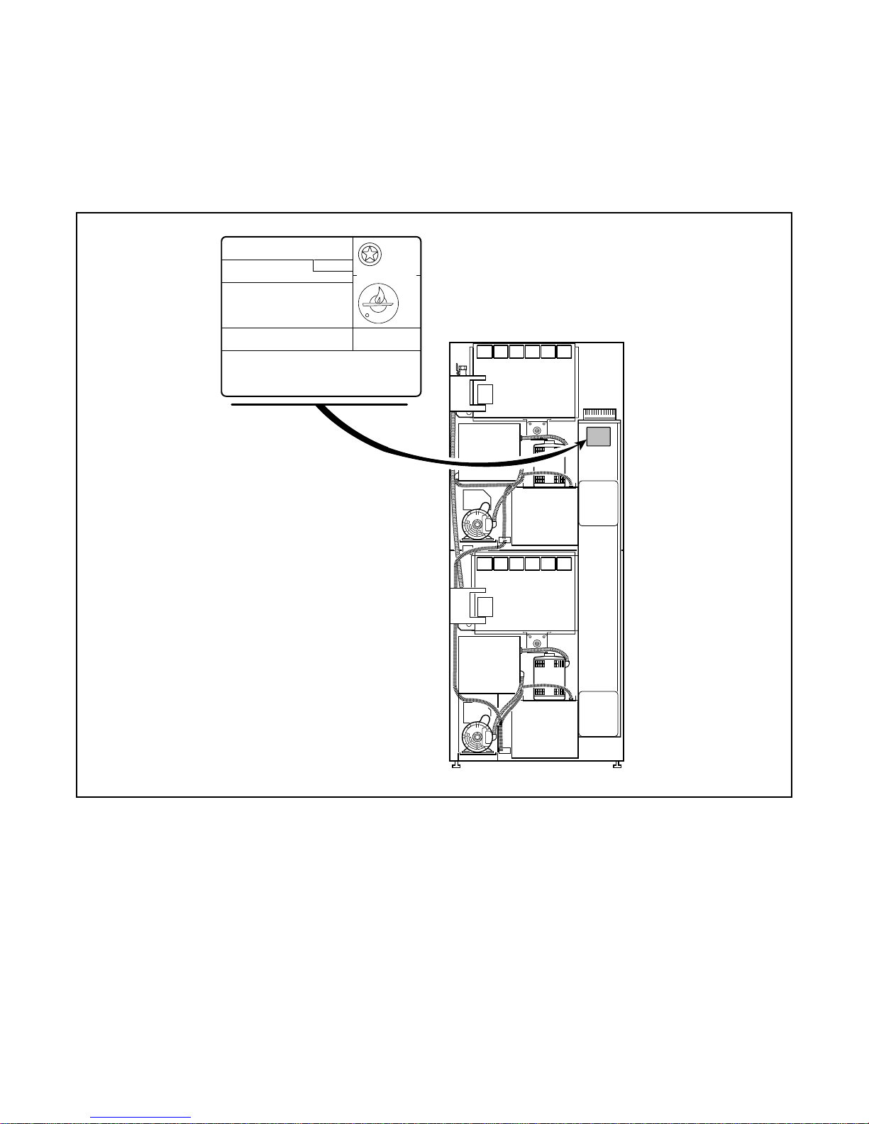
Serial Plate Location
MODEL NO:
SERIAL NO:
V-/ HERTZ/ PHASE
AMPS, WIRES + GROUND
TOTAL kW, MOTOR kW
REQ'D CIRCUIT BREAKER: AMPS
FAN OUTPUT:
@MAX "WC STATIC PRESSURE
EQUIPPED FOR: GAS@ "WC MANIFOLD PRESS.
MIN SUPPLY
PRESSURE:
ANS 72152
CLOTHES DRYER.
VOL II
CGA 72
AMPLFIEDRER
TESTED FOR NATURAL &
LIQUID PETROLEUM GASSES
MAX SUPPLY
PRESSURE:
"WC. "WC.
INPUT: BTU/hr @ BTU/cu.ft.
MADE IN U.S.A./FABRIQUE AU ETATS UNIS/FABRICADO EN LOS ESTADOS UNIDOS 70051001
TMB1961P
When calling or writing for information about your
product, be sure to mention model and seri al numbers.
Model and serial number s are f ound on the seria l plat e
on the rear of the machine an d inside the uppe r loading
door hinge.
Introduction
Customer Service
If literature or replacement parts are required, contact
the source from which the machine was purchased or
contact Alliance Laundry Systems at (920) 748-3950
for the name and address of th e nearest authorized parts
distributor.
For technical assistance, call (920) 748-3121.
Wiring Diagram
The wiring diagram is located inside the contactor or
junction box.
Models starting Serial No. 0309____ or late r will have
the wiring diagram p art number i n the lower portion of
the electrical data on the serial plate.
70291301
© Copyright, Alliance Laundry Systems LLC – DO NOT COPY or TRANSMIT
9
Page 12
Introduction
1
2
3
T002CE3A
1
2
3
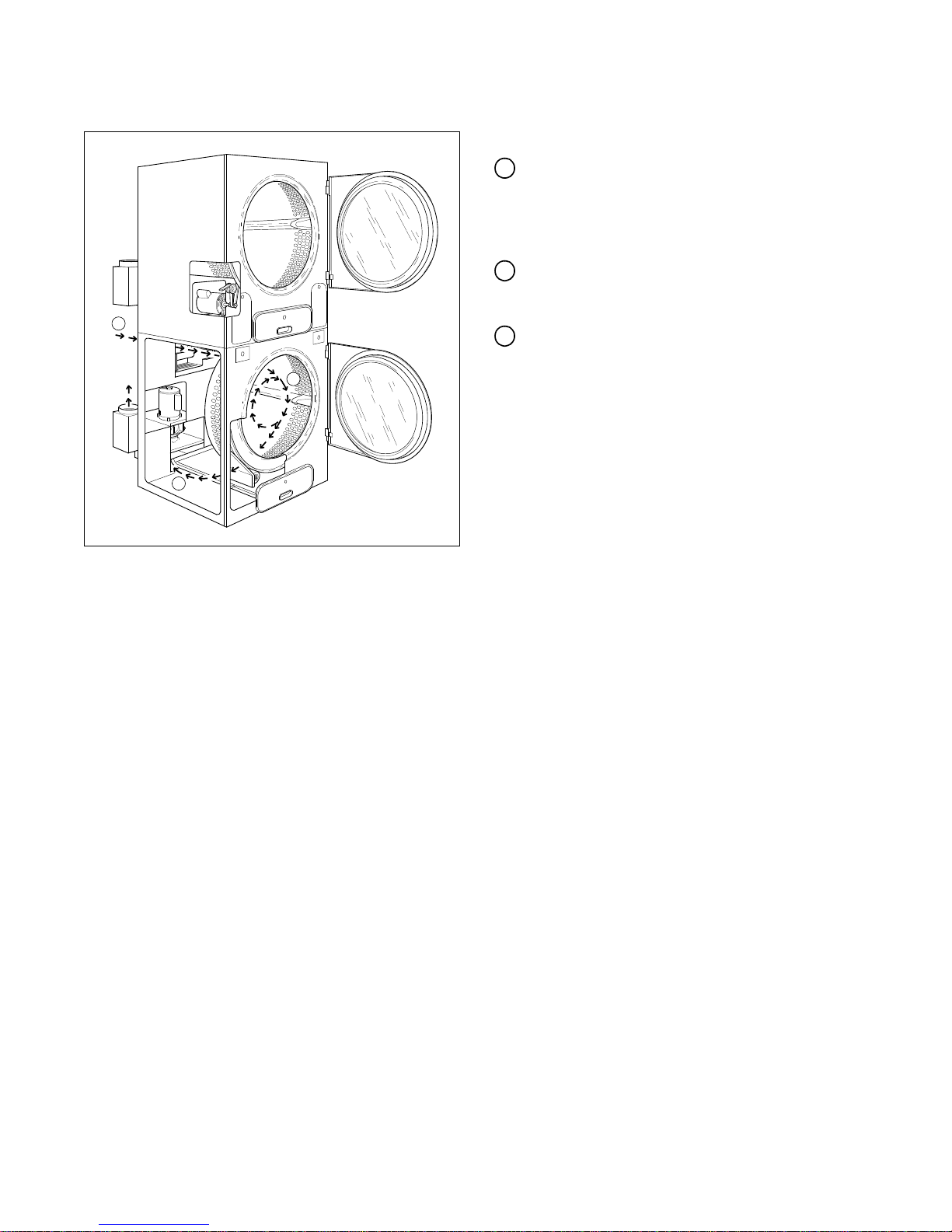
How A Tumble Dryer Works
A tumble dryer uses heated air to dry loads of laundry.
When the motor is started, the exhaust fan pulls
room temperature air in through the air intake at
the rear of the tumble dryer and over the heat
source (burner flame for gas, heating element for
electric, and coil for steam).
The heated air moves into the cyli nder, where it is
circulated through the wet load by the tumbling
action of the cylinder.
The air then passes through the lint filter, exhaust
fan, and is vented to the outdoors.
10
© Copyright, Alliance Laundry Systems LLC – DO NOT COPY or TRANSMIT
70291301
Page 13

Section 3
To reduce the risk of electric shock, fire, explosion, serious injury or death:
• Disconnect electric power to the tumble dryer before servicing.
• Close gas shut-off valve to gas tumble dryer before servicing.
• Close steam valve to steam tumble dryer before servicing.
• Never start the tumble dryer with any guards/panels removed.
• Whenever ground wires are removed during servicing, these ground wires must be
reconnected to ensure that the tumble dryer is properly grounded.
W002R1
WARNING
Troubleshooting
IMPORTANT: Refer to wiring diagram for aid in
testing tumble dryer components.
70291301
© Copyright, Alliance Laundry Systems LLC – DO NOT COPY or TRANSMIT
11
Page 14
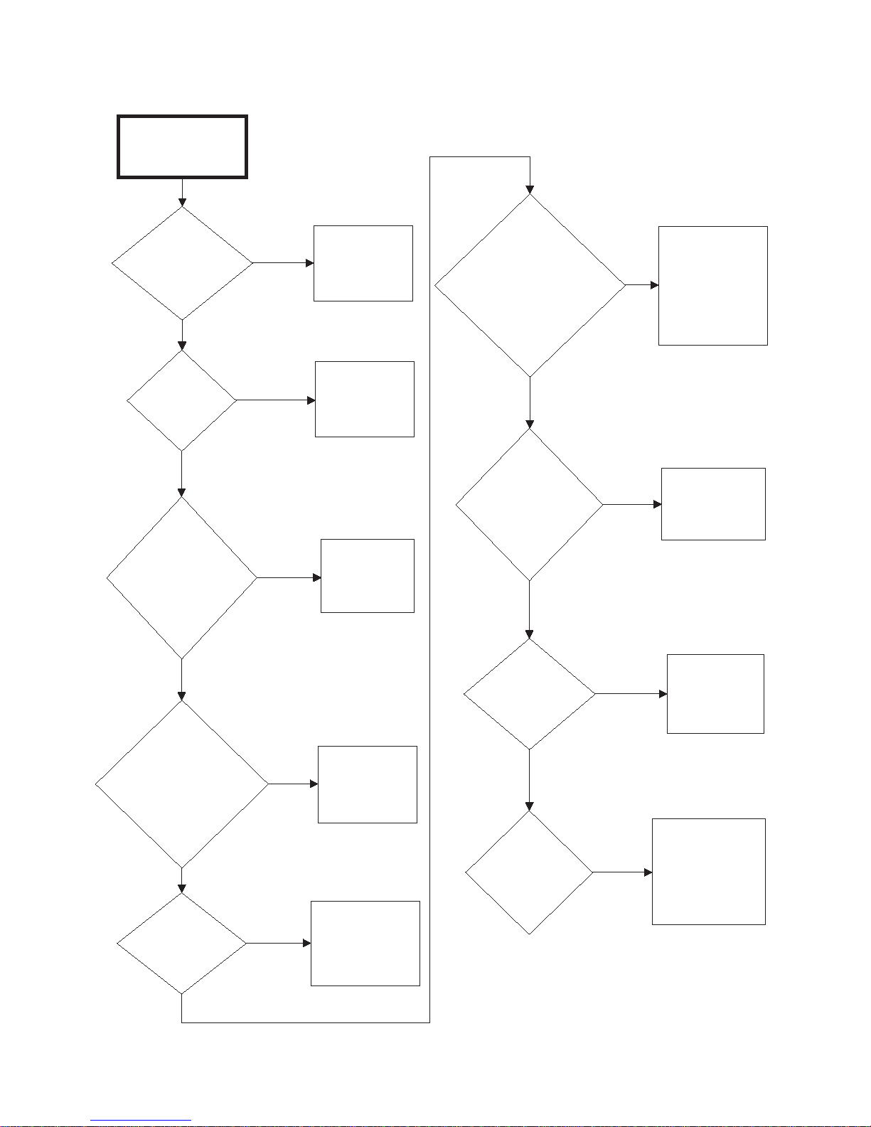
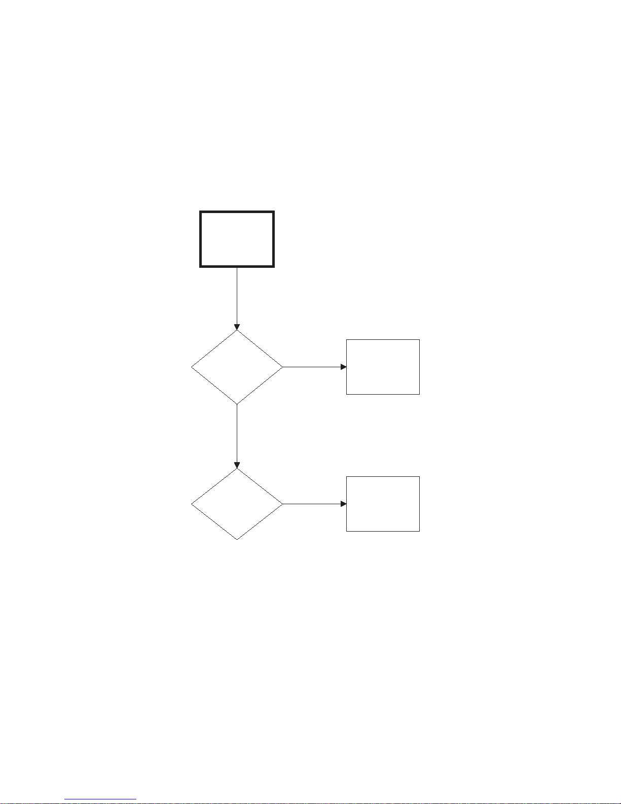
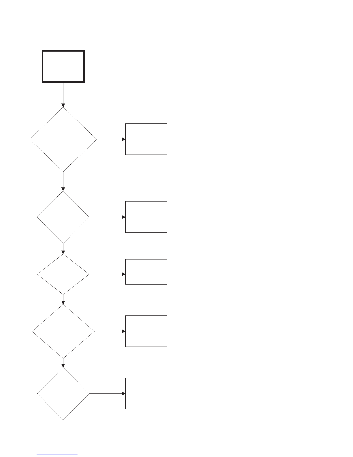
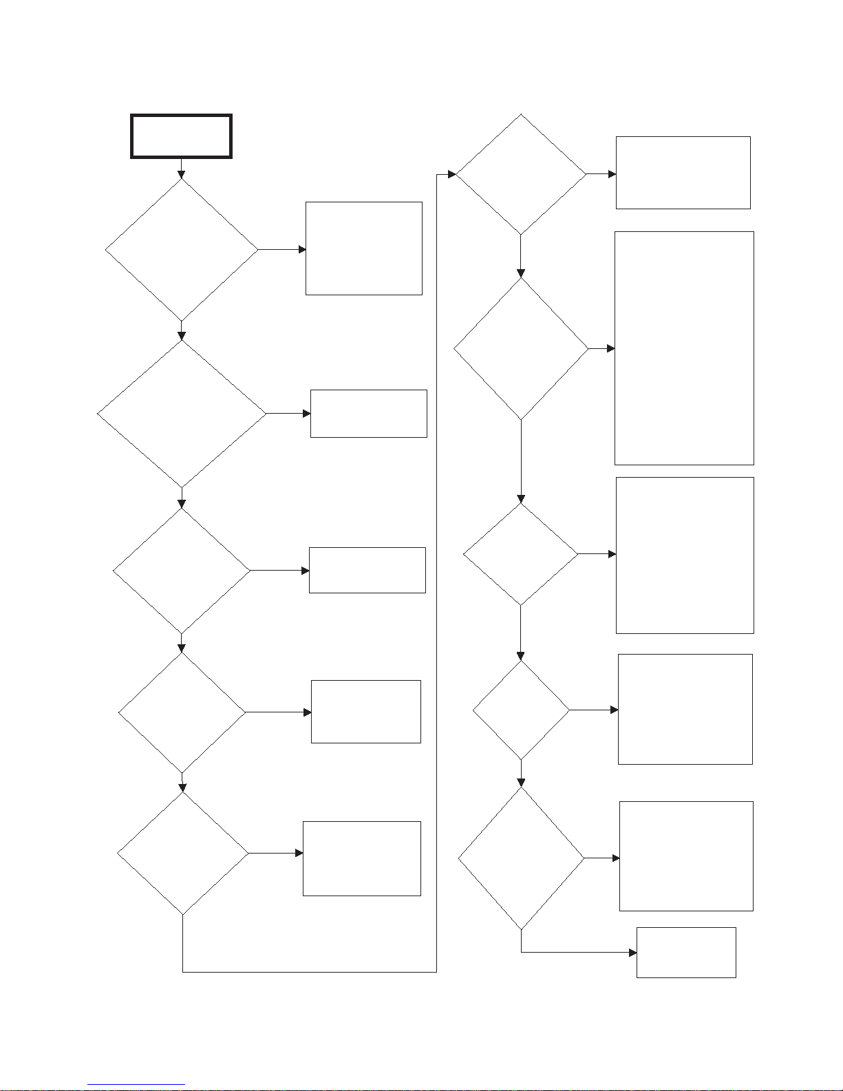
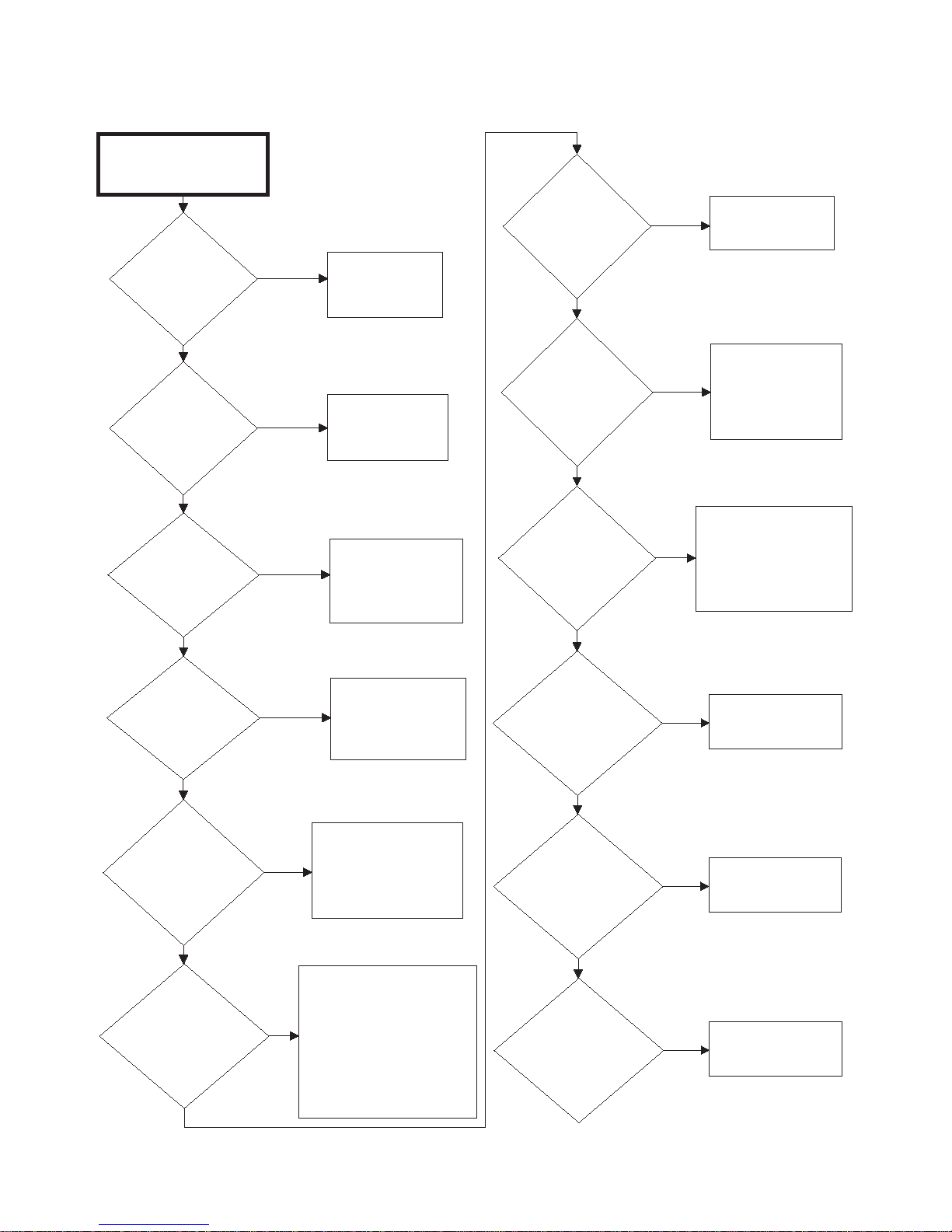
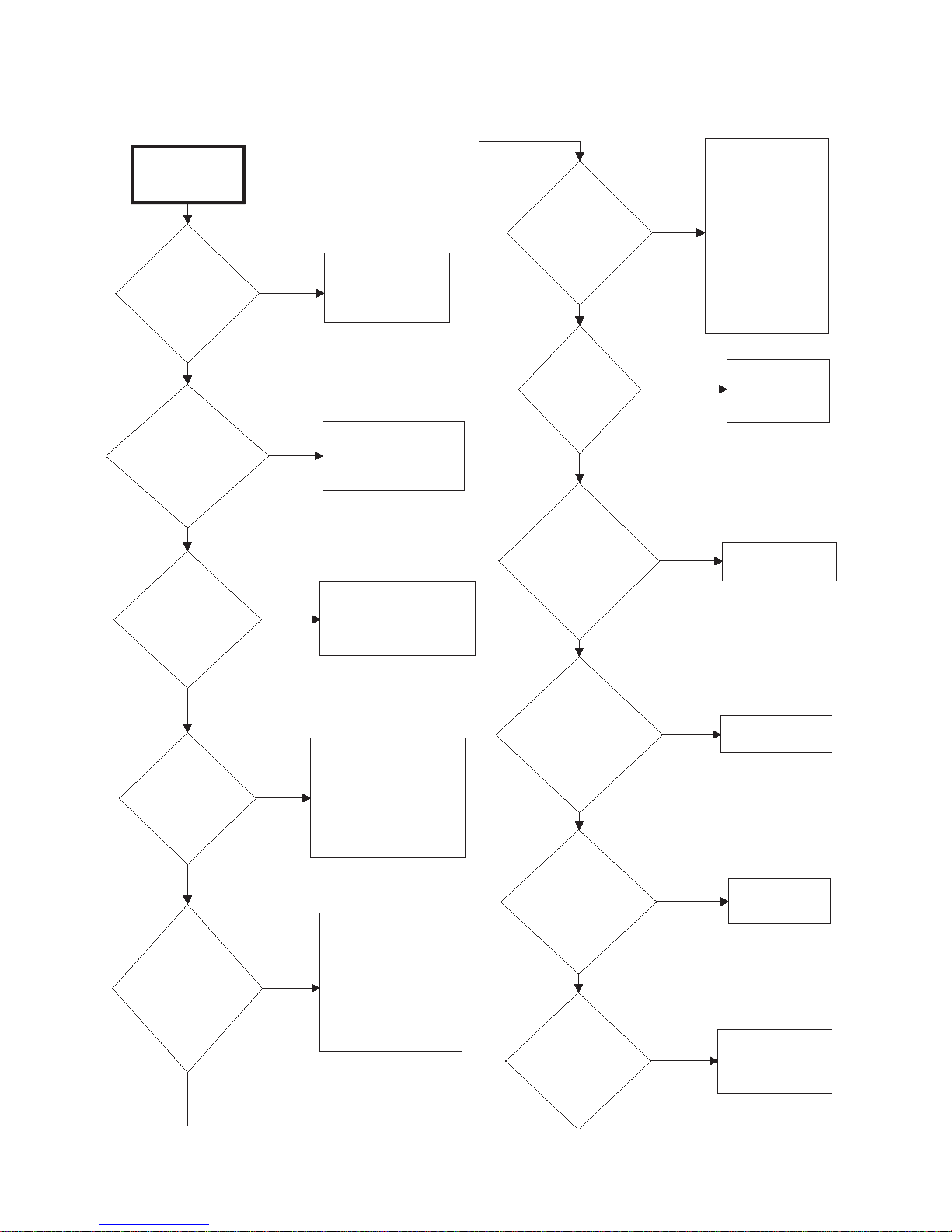
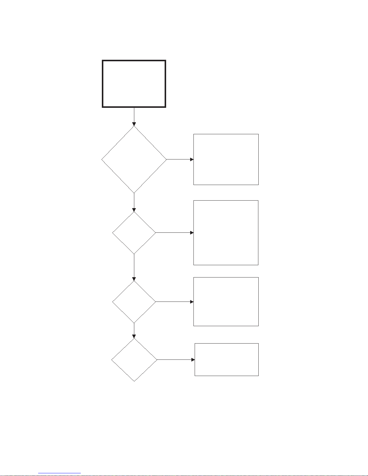
Troubleshooting
Tumbler Does
Not Start
Is motor
relay
inoperative?
Test relay and
replace if
necessary.
Yes
Is
loading door
open?
No
Close loading
door
completely.
Is
drying timer in
an off position
(Manual Timer
Models)?
Yes
Turn drying
timer on.
Check that
proper amount
of coins are
inserted.
Is the
PUSH-TO-
START button
not properly
activated
(Manual Timer
Models)?
Press and
hold PUSH-TO-
START button
for three
seconds.
Is the
electrical power
off or circuit
breaker or fuse
blown?
Close and
lock lint
drawer.
Check fuse
(in junction box)
and replace if
necessary.
Is there a
blown fuse
on tumbler?
Test coin drop
and replace if
inoperative.
Yes
Is coin drop
inoperative?
Is there an
incorrect
amount of coins
inserted into
coin drop?
No
No
Yes
No
Yes
Check power
supply, or
replace fuses.
No
Is the lint
drawer
open?
No
Yes
No
Yes
Yes
TMB2207S
Yes
No
1. Tumble Dryer Does Not Start
12
© Copyright, Alliance Laundry Systems LLC – DO NOT COPY or TRANSMIT
70291301
Page 15
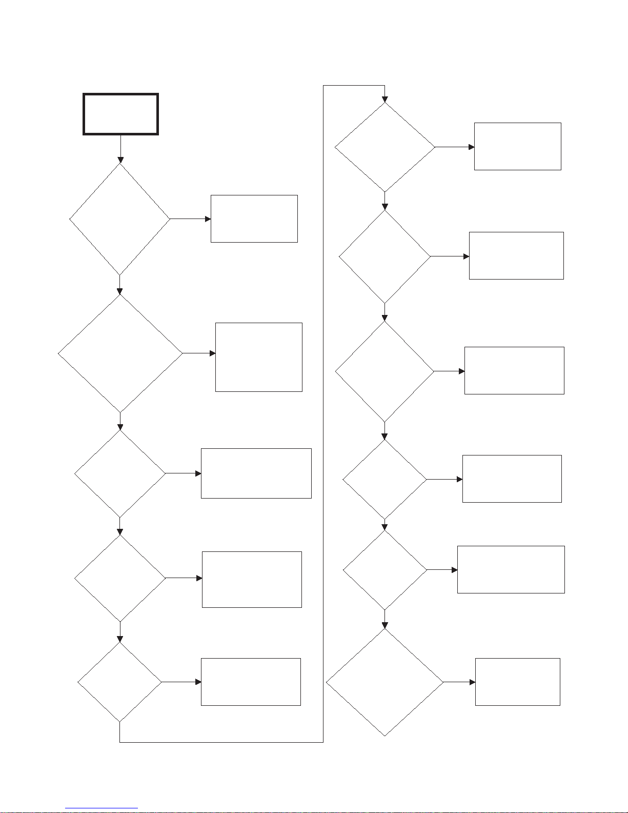
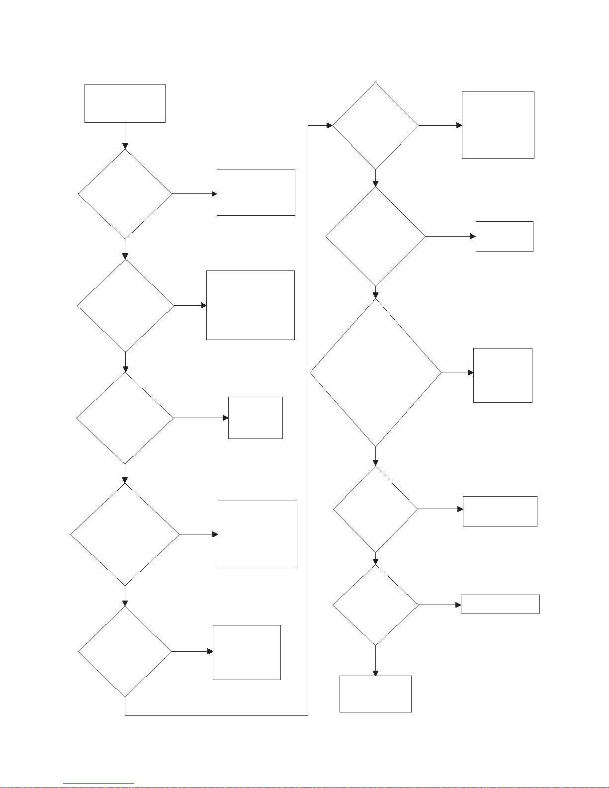
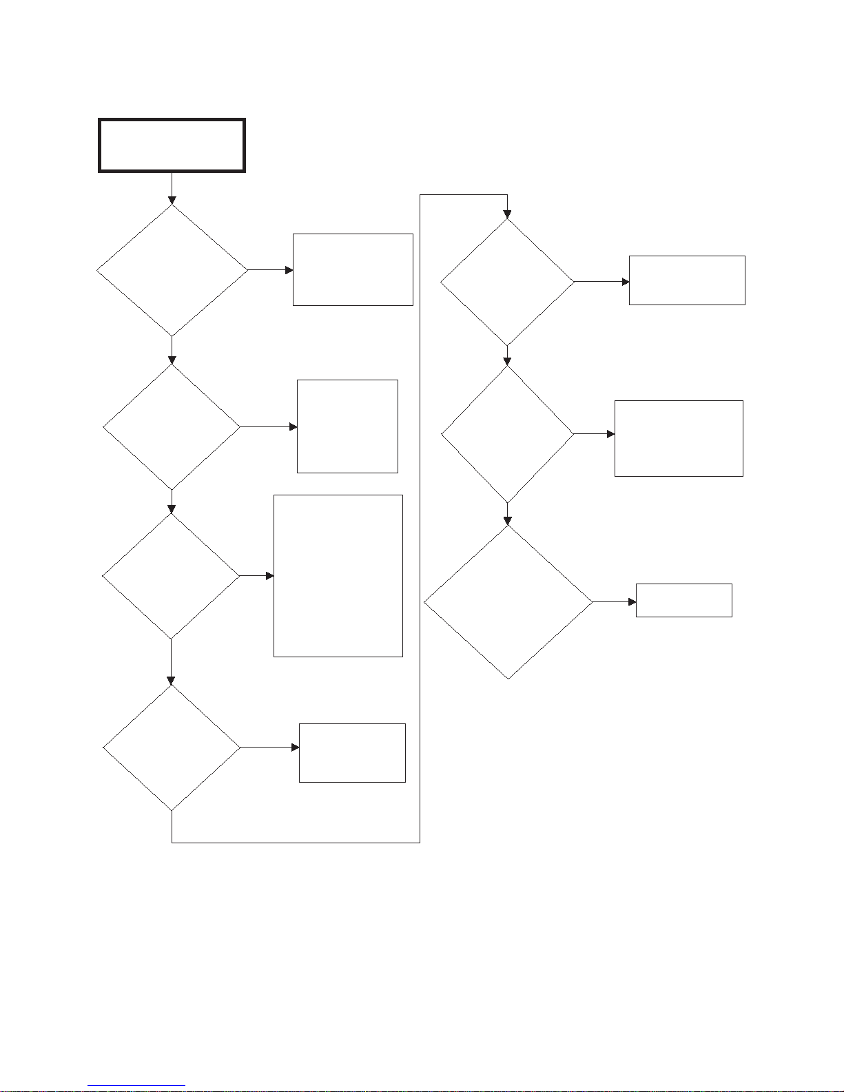
2. Motor Does Not Start
Motor Does
Not Start
Is the
electrical power
off or circuit
breaker fuse
blown?
No
Is the
loading door
switch or lint
drawer switch not
closed or switch
inoperative?
Is the
door switch
improperly
adjusted?
No
Check power
supply, or replace
fuses.
Yes
Close door,
drawer or test
switch and
replace if
inoperative.
Yes
Refer to Installation
Manual for door
switch adjustment.
Yes
Is the start
circuit not
complete?
Yes
Press and hold
PUSH-TO-START
button for three
seconds.
Is the motor
inoperative?
Yes
Have motor tested
and replace if
inoperative.
No
Is the
cylinder or
cylinder motor
binding?
No
Refer to wiring
diagram.
Yes
Replace fan or
motor assembly.
Yes
Replace cylinder,
bearing, rollers, or
motor assembly.
Yes
Is the
transformer
inoperative?
Yes
Test and replace if
necessary.
Is the
motor relay
inoperative?
Yes
Test relay and replace
if inoperative.
Is
the fan or fan
motor
binding?
Is there
broken, loose,
or incorrect
wiring?
No
No
No
Is the
airflow switch
inoperative
(Hyrid Timer
Models)?
Yes
Test switch,
replace or adjust
as required.
No
TMB2208S
No
No
Troubleshooting
70291301
© Copyright, Alliance Laundry Systems LLC – DO NOT COPY or TRANSMIT
13
Page 16
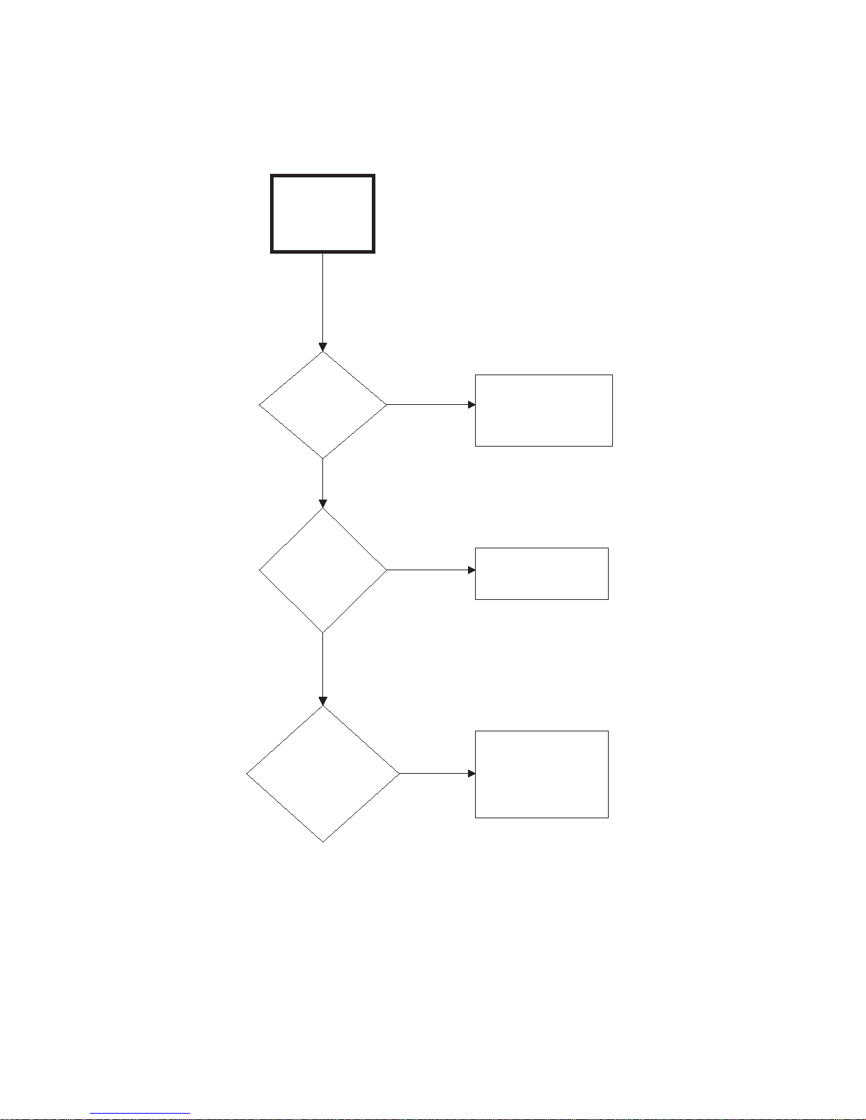
Troubleshooting
TMB1904S
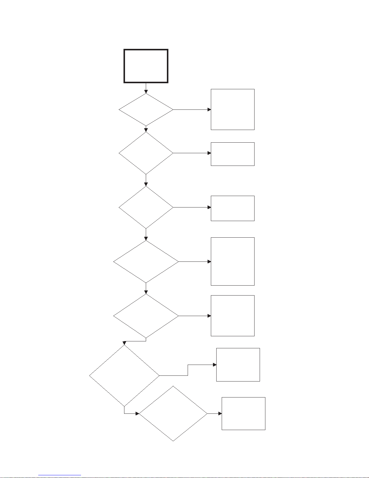
Motor Overload
Protector
Cycles
Repeatedly
Is voltage
correct?
Refer to
Installation
Manual for
electrical
requirements.
Yes
Is clothes
load too
large?
No
Remove part of
load.
Yes
Is clothes
cylinder
binding?
Check cylinder
for binding.
Is wiring
adequate?
No
Yes
No
Check with
local power
company to
ensure that
wiring is
adequate.
Yes
Is make-up
air adequate?
Refer to
Installation
Manual for
make-up air
requirements.
No
Yes
Is there lint
buildup around
tumbler or poor
maintenance?
Clean lint
accumulation
on and around
the motors.
No
Yes
Is there
broken, loose
or incorrect
wiring?
Refer to wiring
diagram.
No
Yes
3. Motor Overload Protector Cycles Repeatedly
14
© Copyright, Alliance Laundry Systems LLC – DO NOT COPY or TRANSMIT
70291301
Page 17
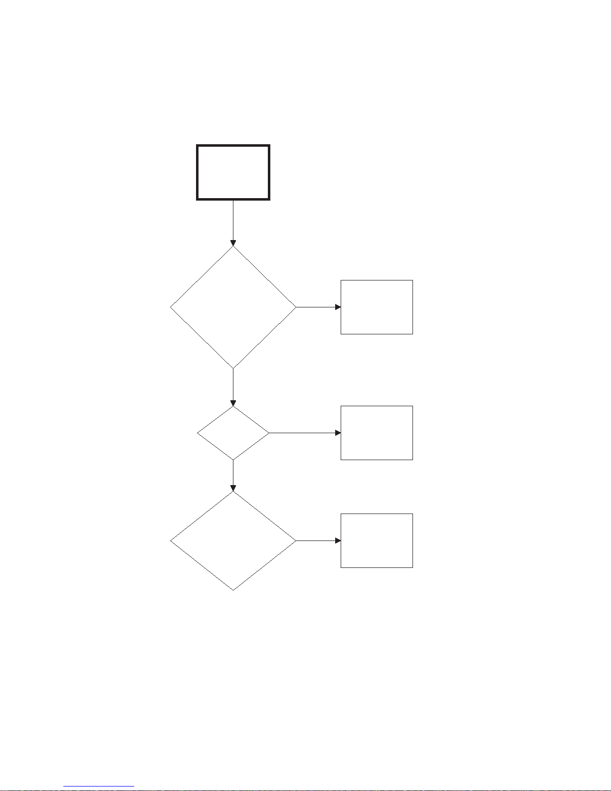
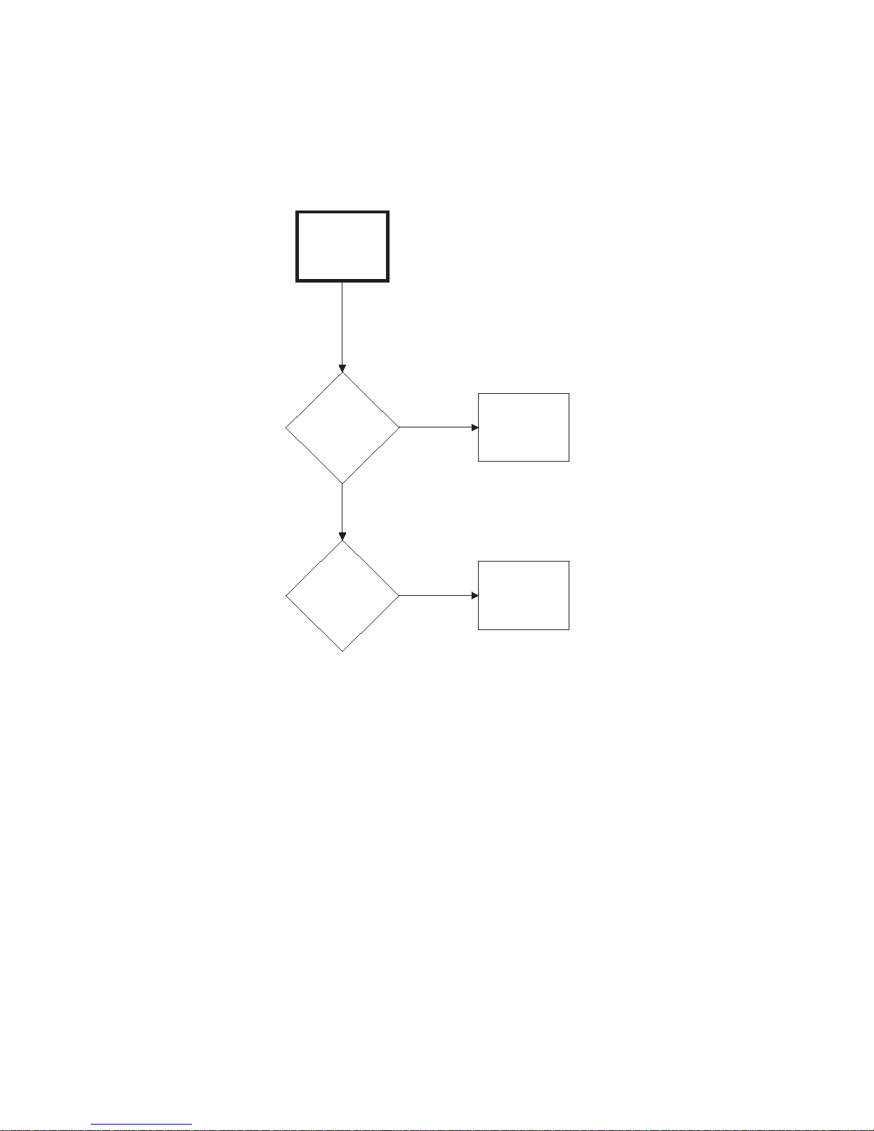
4. Motor Runs But Cylinder Does Not Turn
Motor Runs
But Cylinder
Does Not Turn
Is cylinder
belt
broken?
Replace
cylinder belt.
Is cylinder
binding?
Check cylinder
for binding.
Yes
No
Yes
TMB1905S
Troubleshooting
70291301
© Copyright, Alliance Laundry Systems LLC – DO NOT COPY or TRANSMIT
15
Page 18
Troubleshooting
Motor Does
Not Stop
Is the door
switch or lint
drawer switch
not working
properly?
Test switches
and replace if
inoperative.
Is coin drop
not working
properly?
Test coin drop
and replace if
inoperative.
Is wiring
incorrect?
Refer to wiring
diagram.
Is electronic
control
inoperative?
Replace
electronic
control.
Is motor
relay
inoperative?
Test relay and
replace if
inoperative.
Yes
No
Yes
No
Yes
No
Yes
No
Yes
TMB1906S
5. Motor Does Not Stop
16
© Copyright, Alliance Laundry Systems LLC – DO NOT COPY or TRANSMIT
70291301
Page 19
6. Burner Does Not Ignite
Burner Does
Not Ignite
Is there
an improper or
inadequate exhaust
system?
No
Are there
blown fuses or
tripped circuit breakers
in external electric
supply line?
Is
drying
selector in the
“Cool Down”
portion of
cycle?
No
Refer to
Installation
Manual for
exhaust system
requirements.
Yes
Check fuses or
circuit breaker.
Yes
Reset switch on
microprocessor.
Yes
Is
the cabinet
thermostat
inoperative?
Yes
Test thermostat
and replace if
inoperative.
Is
there an
insufficient gas
supply?
Yes
Open partially closed
gas shut-off valve, or
correct low gas
pressure. Check
manifold pressure
and adjust to
pressure specified on
serial plate. If
pressure cannot be
obtained, have your
local gas company
check main gas
pressure.
No
Is there
inadequate
ductwork and
make-up
air?
No
Tumbler is equipped
for type of gas
specified on serial
plate. If orifices are
different from that
specified on serial
plate, obtain and
install correct orifices.
Yes
Clean lint
compartment. Check
damper for lint
accumulation. Check
ductwork for lint
buildup.
Yes
Refer to Installation
Manual to ensure
that ductwork and
make-up air
openings are sized
accurately.
Yes
Is there
lint
buildup?
Are the
orifices
incorrect?
TMB2209S-a
No
Continued on
next page
Is
stove limit
thermostat 1
inoperative?
Test thermostat 1
and replace if
inoperative.
No
Yes
Is
stove limit
thermostat 2
inoperative?
Test thermostat 2
and replace if
inoperative.
No
No
No
No
Yes
Troubleshooting
70291301
© Copyright, Alliance Laundry Systems LLC – DO NOT COPY or TRANSMIT
17
Page 20
Troubleshooting
Continued from
previous page
Is
there an
improper igniter
to burner tab
clearance?
Are valve coils
inoperative?
No
Clearance
should be
0.110 - 0.140
inch (2.79 - 3.55
mm).
Yes
Check valve
coils and
replace if
necessary.
Yes
Is
there a blown
fuse on
tumbler?
Yes
Check fuse
(located in
control box)
and replace if
necessary.
Is
gas shut-off
valve in the
closed
position?
Yes
Open shut-
off valve.
Is
motor switch
inoperative?
No
Replace IEI
control.
Yes
Replace motor.
Yes
Is the
IEI control
inoperative?
TMB2209S-b
Yes
Connect
ground wire
to ground
terminal.
Is the
ground wire
from Instant
Electronic Ignition
(IEI) board not
connected to
ground
terminal?
No
Is
there broken,
loose or incorrect
wiring?
Yes
Refer
to wiring
diagram.
Is the lint
drawer not
closed
properly?
Yes
Unlock and open
lint drawer. Close
drawer ensuring a
tight fit, then lock.
Is the
airflow switch
inoperative?
Test switch
and replace
if inoperative.
Yes
No
No
No
No
No
No
Continued on
next page
No
6. Burner Does Not Ignite (continued)
18
© Copyright, Alliance Laundry Systems LLC – DO NOT COPY or TRANSMIT
70291301
Page 21

6. Burner Does Not Ignite (continued)
Continued from
previous page
Test and replace
as needed.
Is
wrong
transformer
configuration
harness
installed?
Yes
Check incoming
voltage and install
correct
configuration
harness.
TMB2209S-c
Is there
an inoperative
microprocessor or
hybrid timer?
Yes
No
Is Instant
Electronic
Ignition (IEI)
control in safety
lockout?
Reset IEI control by
opening and closing
loading door. (Non-
CE models only)
Reset IEI by
pressing reset
button on back of
unit. (CE models
only)
No
Yes
Troubleshooting
70291301
© Copyright, Alliance Laundry Systems LLC – DO NOT COPY or TRANSMIT
19
Page 22
Troubleshooting
Burner Ignites and
Goes Out Repeatedly
Is there
insufficient gas
pressure?
Check gas
supply and
pressure.
Yes
Is the cabinet
thermostat
inoperative?
Yes
Test thermostat
and replace if
inoperative.
Is the
exhaust system
improper or
inadequate?
Yes
Refer to
Installation Manual
for exhaust system
requirements.
No
Does
tumbler have
improper
orifices?
Yes
Tumbler is equipped for
type of gas specified on
serial plate. If orifices
are different from that
specified on serial plate,
obtain and install
correct orifices.
No
Is
there excessive
igniter to burner
clearance?
Yes
Clearance
should be
0.110 - 0.140 inch
(2.79 - 3.55 mm).
Is
there
inadequate
make-up air?
Yes
Refer to
Installation Manual
for make-up air
requirements.
No
Is the
thermistor
inoperative?
Yes
No
Replace
thermistor.
Is the control
heater relay
malfunctioning?
Yes
Replace control.
No
Is there
broken, loose or
incorrect
wiring?
Yes
Refer to wiring
diagram.
No
Yes
Repair damper to
working order.
Are the
back draft dampers
locked in closed
position?
No
TMB1908S
No
Is
stove limit
thermostat 1
inoperative?
Test thermostat 1
and replace if
inoperative.
No
Yes
Is
stove limit
thermostat 2
inoperative?
Test thermostat 2
and replace if
inoperative.
No
No
Yes
7. Burner Ignites and Goes Out Repeatedly
20
© Copyright, Alliance Laundry Systems LLC – DO NOT COPY or TRANSMIT
70291301
Page 23
8. Burner Does Not Shut Off
Burner Does
Not Shut Off
Are there
impurities on gas
valve seat,
preventing valve
from closing?
Replace gas
valve.
Is wiring
correct?
Refer to wiring
diagram.
Is control heater
relay
malfunctioning?
Replace
control.
Yes
No
Yes
No
Yes
TMB1909S
Troubleshooting
70291301
© Copyright, Alliance Laundry Systems LLC – DO NOT COPY or TRANSMIT
21
Page 24
Troubleshooting
Clothes Do Not
Dry
Is there
enough heating
time allocated for
the load?
Yes
Is the burner
igniting?
Start cycle again
with enough time to
dry load.
No
Refer to
Burner Does Not
Ignite flowchart.
No
Remove excess
water.
Is
the clothes
load too
large?
Yes
Remove part of
load. Maximum
load is 30 pound
dry weight (cotton
load) for 30 pound
Tumbler, etc.
Is the
exhaust system
improper or
inadequate?
Yes
Refer to Installation
Manual for exhaust
system equirements.
No
Is
the voltage
incorrect?
No
Refer to
Burner Ignites
and Goes Out
Repeatedly
flowchart.
Yes
Set selector
for higher
setting.
Yes
Refer to Installation
Manual for electrical
requirements.
Yes
Is there
inadequate
make-up
air?
Yes
Refer to Installation
Manual for make-up
air requirements.
Is the
exhaust duct to
the outside
blocked?
Yes
Clean duct to
remove blockage.
Is
the drying
selector
improperly
set?
Does
the burner ignite
and go out
repeatedly?
No
No
No
TMB2210S-a
No
Continued on
next page
Is there
too much water in
articles being
dried?
Yes
No
Yes
No
9. Clothes Do Not Dry
22
© Copyright, Alliance Laundry Systems LLC – DO NOT COPY or TRANSMIT
70291301
Page 25
9. Clothes Do Not Dry (continued)
Continued from
previous page
Is the lint screen
clogged?
Is the thermistor
inoperative?
No
Clean lint screen.
Yes
Replace thermistor.
Yes
Is the
exhaust
damper
binding?
Yes
Adjust damper so it
turns freely.
Is the
cylinder speed
too fast?
Yes
Check belt is not
riding on outer
diameter of motor
pulley.
TMB2210S-b
No
No
Troubleshooting
70291301
© Copyright, Alliance Laundry Systems LLC – DO NOT COPY or TRANSMIT
23
Page 26
Troubleshooting
10.Tumble Dryer Overheating
Tumbler
Overheating
Does
tumbler
have incorrect
main burner
orifices?
No
Is gas
pressure too high or
low?
No
Is the
make-up air
inadequate?
Ye s
Ye s
Ye s
Obtain and install
correct orifices.
Adjust gas pressure
as specified on
serial plate.
Refer to Installation
Manual for make-up
air requirements.
Is the
thermistor
sensor
inoperative?
No
Is the
exhaust
damper
binding?
No
Is the
control heater
relay
malfunctioning?
No
Ye s
Ye s
Ye s
Check wiring to
ensure thermistor
is connected.
Replace
thermistor if
necessary.
Remove lint build-
up on thermistor.
Adjust damper
so it turns
freely.
Replace control.
No
Is there
lint buildup?
No
Is the
exhaust system
restricted or
inadequate?
No
Ye s
Ye s
Clean lint
compartment. Check
damper for lint
accumulation. Check
ductwork for lint
buildup.
Remove obstruction
or lint build up from
exhaust ductwork.
Refer to Installation
Manual for exhaust
system
requirements.
Are
the safety covers
missing, allowing
cool air to enter
tumbler?
No
Is the
lint screen
clogged with
fabric
softener?
No
Are there
holes in cabinets
due to foreign
objects?
Ye s
Ye s
Ye s
Replace covers.
Replace lint
screen.
Repair/replace
cabinet
components.
TMB1911S
24
© Copyright, Alliance Laundry Systems LLC – DO NOT COPY or TRANSMIT
70291301
Page 27
11.Burner Not Burning Properly
Burner Not Burning
Properly
Is there lint/dirt in
burner tube?
Is the gas
pressure too high
or low?
No
Disassemble
burner and
blow out lint/dirt.
Yes
Check serial
plate on back of
tumbler for
correct gas
pressure.
Yes
Is
the airflow
switch not
functioning
properly?
Yes
Replace airflow
switch.
Is there
inadequate
make-up
air?
Yes
Refer to
Installation Manual
for make-up air
requirements.
TMB2211S
No
Yes
Clean off lint.
Is there lint buildup
around gas valve
spud?
No
Does
the tumbler have
incorrect
orifices?
Yes
Tumbler is equipped
for the type of gas
specified on serial
plate. If orifices are
different from that
specified on serial
plate, obtain and
install correct
orifices.
Is the
exhaust duct
restricted or
blocked?
Yes
Disassemble
and clean
exhaust system.
No
No
No
Troubleshooting
70291301
© Copyright, Alliance Laundry Systems LLC – DO NOT COPY or TRANSMIT
25
Page 28
Troubleshooting
Loading Door
Opens During
Operation
Is tumbler
improperly
leveled?
Refer to Installation
Manual for leveling
leg adjustment.
Is clothes
load too
large?
Remove part of load
and restart tumbler.
Is loading
door strike
adjusted
incorrectly?
Refer to
Adjustments
Section for strike
adjustment.
Yes
No
Yes
No
Yes
TMB1913S
NOTE: All tumble dryer panels must be in
place and on the machine for proper
operation.
12.Loading Door Opens During Operation
26
© Copyright, Alliance Laundry Systems LLC – DO NOT COPY or TRANSMIT
70291301
Page 29
13.Cylinder Continues to Spin with Door Open
Cylinder
Continues To
Spin With Door
Open
Is door
switch
inoperative?
Replace
door switch.
Yes
TMB2186S
Is
motor relay
inoperative?
Replace relay
in control box.
No
Yes
NOTE: All tumble dryer panels must be in place and on the
machine for proper operation.
Troubleshooting
70291301
© Copyright, Alliance Laundry Systems LLC – DO NOT COPY or TRANSMIT
27
Page 30
Troubleshooting
Coin Does Not Fall
Into Coin Vault or Coin
Drop Sensor Does Not
Register That Coin
Has Been Entered
Is proper
electrical
power
supplied to
coin drop?
Incorrect electrical
connection may
prevent coins from
registering in coin drop.
Refer to wiring
diagram.
No
Is
machine
level?
Machines that are not
level may prevent coins
from following through
required check stages
of drop. Refer to
Installation Manual
for instructions on
leveling machine.
Is coin
drop
clean?
Residue or lint build-up
may prevent coins from
following through
required check stages
of drop. Clean coin
drop.
Yes
No
Yes
No
TMB1915S
Is sensor
operative?
Yes
Replace coin drop
sensor.
No
14.Coin Does Not Fall into Coin Vault or Coin Drop Sensor Does Not Register
That Coin Has Been Entered
IMPORTANT: Never use oil to correct coin drop problem. Oil residue will prevent coins from rolling
properly.
IMPORTANT: Do not bend or damage mechanical parts within coin drop.
28
© Copyright, Alliance Laundry Systems LLC – DO NOT COPY or TRANSMIT
70291301
Page 31

Troubleshooting
Coin Drop
Cover
Coin Return
Button
Tension Spring
MIX6B
Coin Drop
Cover
DRY2088N
Cover Catch
Tension Spring
Small Flathead
Screwdriver
Right Side of
Tension Spring
Left Tab
MIX3B
Tabs
Center Tab
Troubleshooting Coin Drop
If coin drop is not accepting coins, perform the
following:
1. Clean coin drop. Refer to Paragraph 17.
2. On electronic coin drops with an old-style
tension sp ring (shown in Figure 1 and Figure 3),
test and replace tension spring using the
following instructions.
Remove Coin Drop From Machine
1. Disconnect electrica l power to machin e and drop.
2. Remove coin drop from machine.
Test Tension Spring
1. Push coin return button to open and close coin
drop cover to clear possible coin jams. Refer to
Figure 1.
Replace Tension Spring
1. Move tension spri ng d o wnwar d u nti l cover catch
is free. Refer to Figure 3.
Figure 3
2. Open cover for coin drop.
3. Place a small flathead screwdriver under right
side of tension spring and lift up. Refer to
Figure 4.
MIX7B
Figure 1
2. Manually hold down coin drop cover and insert
coin. Refer to Figure 2.
Figure 2
3. If coin drop now operates properly, replace
tension spring using instructions on following
pages.
MIX2B
Figure 4
4. Use screwdriver to move spring approximately 3
mm to left.
5. Lift spring over left tab. Refer to Figure 4.
6. Rotate spring clock wise, 4 0 to 60 de grees, un til it
is free from right tabs. Refer to Figure 5.
70291301
© Copyright, Alliance Laundry Systems LLC – DO NOT COPY or TRANSMIT
Figure 5
29
Page 32

Troubleshooting
MIX4B
Clip
MIX8B
Slot
MIX5B
Small Flat
Screwdriver
Center
Tab
Left Tab
7. Use screwdriver to remove spring from center
tab. Refer to Figure 5.
8. Lift spring, with attached clip, off drop.
9. Remove clip from spring. Refer to Figure 6.
Figure 6
10. Attach clip to new tension spring, Part No. 209/
00598/02.
11. Place clip, installed on spring, in slot on coin
drop. Refer to Figure 7.
12. Use a small flathead screwdriver to push spring
under center tab. Refer to Figure 8.
Figure 8
13. Lift spring gently to place in position under left
tab.
14. Push spring to right until it snaps into position.
Refer to Figure 4.
15. Close coin drop cover.
16. Move tension spring over cover catch. Refer to
Figure 3.
Figure 7
Reinstall Coi n Drop Into Machine
1. Reinstall coin drop into machine.
2. Reconnect electrical power to machine and drop.
3. Add a coin to drop to verify that coin drop is
operating properly and that electrical connection
is working properly.
30
© Copyright, Alliance Laundry Systems LLC – DO NOT COPY or TRANSMIT
70291301
Page 33

Section 4
To reduce the risk of electric shock, fire, explosion, serious injury or death:
• Disconnect electric power to the tumble dryer before servicing.
• Close gas shut-off valve to gas tumble dryer before servicing.
• Close steam valve to steam tumble dryer before servicing.
• Never start the tumble dryer with any guards/panels removed.
• Whenever ground wires are removed during servicing, these ground wires must be
reconnected to ensure that the tumble dryer is properly grounded.
W002R1
WARNING
1
Adjustments
15.Troubleshooting and Cleaning
Coin Drop
When a coin is placed into coin slot, the coin should
roll down drop and be heard dropping into coin vault.
If coin does not fall into coin vault or if coin drop
sensor does not register that coin has been entered,
follow troubleshooting instructions below.
16.Troubleshooting Coin Drop
Is proper electrical power supplied to coin drop?
Incorrect electr ical connection may pre vent coins from
registering in coin drop. Refer to wiring diagram and
service manual for proper connections.
Is machine level? Machines that are not level may
prevent coins from following through required check
stages of drop. Refer to Installation Instructions for
instructions on leveli ng machine.
Is coin drop clean? Residue or lint build-up may
prevent coins from following through required check
stages of drop. Refer to Cleaning Coin Drop
instructions below.
levels of residue or lint build-up. Follow the
instructions below for cleaning the coin drop.
1. Disconnect electrica l power to mach ine and dr op.
2. Remove coin drop from machine.
3. Open cover of c oin drop. Refer to instruc tions f or
your coin drop below.
Coin Drops with Old-Style Spring
Refer to
Figure 9
.
IMPORTANT: Never use oil to correct coin drop
problems. Oil residue will prevent coins from
rolling proper ly.
IMPORTANT: Do not bend or damage mec hani cal
parts within coin drop.
17.Cleaning Coin Drop
The electronic coin drop should be cleaned once a
year . Clea n the dr op more oft en if it i s exposed to high
70291301
© Copyright, Alliance Laundry Systems LLC – DO NOT COPY or TRANSMIT
1 Spring
Figure 9
a. Move spring downward until cover catch is
free. Refer t o Figure 10.
NOTE: Do not lift or overbend the spring in any
direction.
DRY2088N
DRY2088N
31
Page 34

Adjustments
1
1
1
DRY2408N
1
1 Catch
Figure 10
b.Open cover for coin drop. Refer to
Figure 11.
DRY2088N
DRY2088N
Coin Drops with New-Style Spring
Refer to
Figure 12
1 Spring
.
Figure 12
c. Open cover of coin drop. Refer to Figure 13.
DRY2404N
1 Cover
Figure 11
NOTE: Do not overbend the spring by opening
cover too far.
DRY2408N
DRY2089N
1 Spring
Figure 13
4. Clean the coin path with a soft brush and wipe
exposed surfaces with an alcohol moistened
cloth. Refer to Figure 14 and Figure 15.
32
© Copyright, Alliance Laundry Systems LLC – DO NOT COPY or TRANSMIT
70291301
Page 35

Adjustments
DRY2090N
OLD-STYLE SPRING COIN DROP
DRY2405N
NEW-STYLE SPRING COIN DROP
1
1
1
.
DRY2407N
1 Light Sensors
Figure 14
DRY2090N
7. Close cover for coin drop.
Figure 17
8. Coin Drops with OLD-Style Spring – Move
spring back over cover catch.
9. Reinstall coin drop into machine.
10. Reconnect electrical power to machine and drop.
11. Add a coin to drop to verify that coin drop is
operating properly and that electrical connection
is working properly.
Figure 15
5. Clean residue from coin rail with an alcohol
moistened cloth. Refer to Figure 16.
1 Alcohol Moistened Cloth
Figure 16
6. Clean light sensors with a soft brush or air spray
duster. Refer to Figure 17.
DRY2405N
DRY2406N
70291301
© Copyright, Alliance Laundry Systems LLC – DO NOT COPY or TRANSMIT
33
Page 36

Adjustments
Notes
34
© Copyright, Alliance Laundry Systems LLC – DO NOT COPY or TRANSMIT
70291301
Page 37

Section 5
To reduce the risk of electric shock, fire, explosion, serious injury or death:
• Disconnect electric power to the tumble dryer before servicing.
• Close gas shut-off valve to gas tumble dryer before servicing.
• Close steam valve to steam tumble dryer before servicing.
• Never start the tumble dryer with any guards/panels removed.
• Whenever ground wires are removed during servicing, these ground wires must be
reconnected to ensure that the tumble dryer is properly grounded.
W002R1
WARNING
Electronic Control Troubleshooting
18.Theory of Operation of Instant Electronic Ignition
IMPORTANT: The Non-CE Marked Instant
Electronic Ignition system wi ll attempt to light the
gas by sparking for approximately 12 seconds. If
gas ignition does not take place within
approximately 12 seconds, the Instant Electronic
Ignition control will go into safety lockout and the
valve will no longer open u ntil Instant Electronic
Ignition control is reset. To reset Instant Electronic
Ignition control, remove power from control by
opening and closing the tumble dryer door. If
condition persists, chec k that the gas s hut- off val ve
is in “on” position and that the gas service is
properly connected.
If condition persists:
a. Check resistance of high tension lead
(approximately 1000 ohms/inch), and replace
if not within resistance range.
b. Check voltage present at valve.
c. Check that machine is properly grounded.
d. Check the igniter gap (gap should be .110 to
.140 inch).
e. Check that burner ports are not blocked or
plugged under the igniter.
70291301
© Copyright, Alliance Laundry Systems LLC – DO NOT COPY or TRANSMIT
35
Page 38

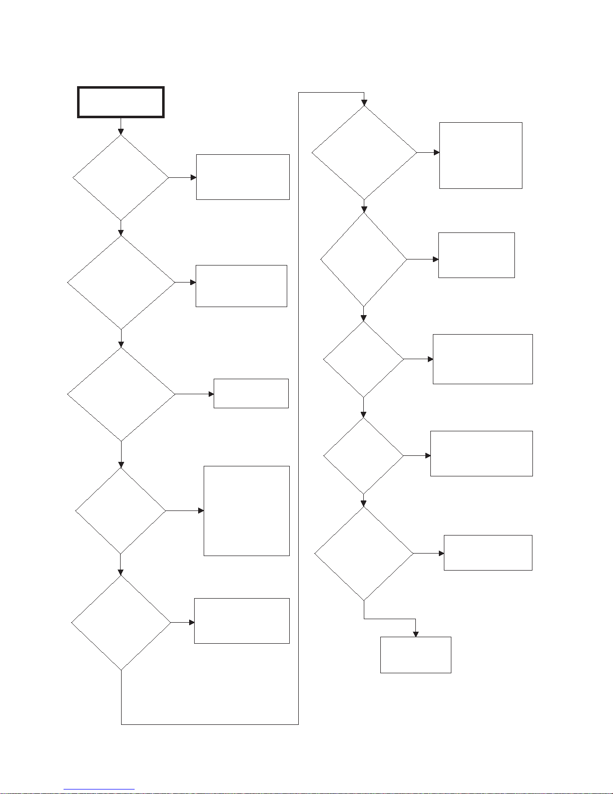
Electronic Control Troubleshooting
Check the following:
- IR communication disabled by
manual programming.
- Is the IR window on the control
covered or blocked.
- if needed, change electronic
control board.
Check the following:
- low battery on microwand.
- is the IR window covered or
blocked on the control.
- if needed replace the
electronic control.
- is the IR cap properly attached
to the microwand.
Communication
sequence checks
out.
Attempt to
communicate with
the electronic
control from the
microwand.
Aim microwand
closer and try again.
Is there a response of
any kind from the
electronic control?
Does the control
respond?
Does the electronic
control display E:OF
or -C-?
NO
YES
-C-
E:OF
NO
YES
Single and stacked.
Gas and electric heat.
Single and three phase
supply.
T027D
19.Cannot Perform Infrared (IR) Communication
T027D
36
© Copyright, Alliance Laundry Systems LLC – DO NOT COPY or TRANSMIT
70291301
Page 39

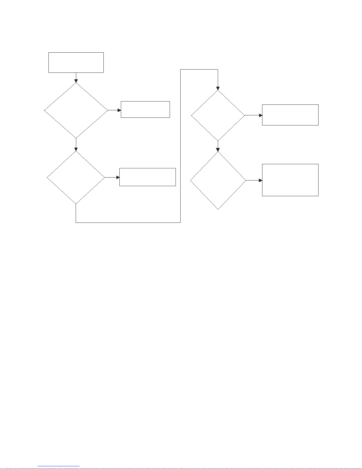
20.Coins Ignored When Entered
Does the display on the
EDC control increment
properly?
Is connector H2 firmly
seated in its
receptacle?
Is the 3 pin connector
between coin drop and
control connected
correctly?
Are wires exiting coin
drop optical sensor
cracked or broken?
Exit diagnostic
testing and reset
control. (Prompting
for vend price)
Reconnect and run
diagnostic test
again.
Reconnect and run
diagnostic test
again.
Replace coin drop
or optic switch.
Replace coin drop
or optic switch.
If problem still
exists then replace
the EDC control.
Start coin drop
diagnostic tests.
YES
NO
YES
YES
NO
YES
NO
NO
Single and stacked
units. Gas and electric
heat. Single and three
phase voltage.
TMB1822S
Electronic Control Trouble shooting
TMB1822S
70291301
© Copyright, Alliance Laundry Systems LLC – DO NOT COPY or TRANSMIT
37
Page 40

Electronic Control Troubleshooting
Is there voltage at
H4-6 on the
electronic
control?
Replace
electronic
control.
Is there power supplied
to the unit?
NO
Is there voltage to input
of primary fuses?
Is there voltage to
output side of the
primary fuses?
Is there voltage across
terminals 1 & 2 of
transformer primary?
Plug unit in and
run it.
Correct wiring
between primary
fuses and power
supply.
Replace primary
fuse(s).
Correct wiring
between primary
fuses and
transformer.
Is there voltage across
terminals 2 & 3 of
transformer
secondary?
Replace
transformer.
Is there voltage at
the input of the
secondary fuse?
Is there voltage to
output side of
secondary fuse?
Correct wiring
between secondary
fuse and
transformer.
Replace secondary
fuse.
NO
NO
NO
NO
NO
NO
YES
(1)
(6)
(7)
(8)
(9)
(10)
(11)
(2)
(3)
(4)
(5)
YES
YES
YES
YES
YES
YES
Is there voltage to
N.O. of door
switch?
With door closed is
there voltage to
COM of door
switch?
Is there voltage to
N.O. of lint drawer
switch?
Is there voltage to
COM of lint drawer
switch with lint
panel closed?
Check for proper
operation replace if
necessary.
Correct wiring
between N.O. on lint
drawer and COM on
door switch.
Correct wiring
between N.O. and
output of secondary
fuse.
Check for proper
function of door
switch replace if
necessary.
Correct wiring
between H4-6 of
electronic
control and
COM of lint drawer
switch.
YES
YES
YES
YES
YES
NO
NO
NO
NO
NO
Single and stacked
units. Gas and electric
heat. Single and three
phase supply.
Reference voltage
checks to transformer
neutral.
T028D
21.Control Display – Door Open Light “On”
38
© Copyright, Alliance Laundry Systems LLC – DO NOT COPY or TRANSMIT
T028D
70291301
Page 41

Electronic Control Trouble shooting
TMB1788S
1
2
3
4
5
7
6
8
9
10
11
22.Control Display – “door” Error on 25, 30, Stacked 30 and 35 Pound
Tumble Dryers with 24 Volt EDC Controls
70291301
© Copyright, Alliance Laundry Systems LLC – DO NOT COPY or TRANSMIT
39
Page 42

Electronic Control Troubleshooting
23.Control Display – No Visible Display – OPL Microprocessor Models
Gas, steam
and electric heat.
Single and three
phase supply.
Is there voltage
supplied to the unit?
YES
Note: Reference voltage to
Is there voltage to the
input side of the
primary fuse(s)?
YES
Is there voltage to the
output side of the
primary fuse(s)?
YES
Is there voltage
across the primary side
of the transformer?
supply neutral.
NO
NO
NO
NO
Connect supply
voltage and run unit.
Correct wiring
between primary
fuse and supply.
Replace primary
fuse.
Correct wiring
between transformer
and primary fuse.
Is there voltage across
fuse on OPL Micro?
YES
Replace fuse.
NO
Replace OPL Micro.
YES
Is there voltage across
1 & 4 of transformer
secondary?
YES
Is there voltage across
terminals H3-3 &
H3-4 on OPL Micro?
YES
NO
NO
Replace transformer
Correct wiring
between OPL Micro
and transformer
secondary.
TMB1823S
TMB1823S
40
© Copyright, Alliance Laundry Systems LLC – DO NOT COPY or TRANSMIT
70291301
Page 43

24.Control Display – No Visible Display – Power On
Single and stacked
units. Gas and electric
heat. Single and three
phase supply.
Is there voltage across
H4-2 & H4-5 on the
EDC control?
Replace EDC
Control.
Is there voltage at
the input of the
secondary fuse?
Electronic Control Trouble shooting
NOYES
Correct wiring
between secondary
fuse and
transformer.
NO
Is there power supplied
to the unit?
YES
Is there voltage to input
of primary fuses?
YES
Is there voltage to
output side of the
primary fuses?
YES
Is there voltage across
terminals 1 & 2 of
transformer primary?
NO
NO
NO
NO
Plug unit in and run
it.
Correct wiring
between primary
fuses and power
supply.
Replace primary
fuse(s).
Correct wiring
between primary
fuse and
transformer.
YES
Is there voltage to
output side of
secondary fuse?
YES
Correct wiring
between H4-2 and
secondary fuse.
NO
Replace secondary
fuse.
YES
Is there voltage across
terminals 2 & 3 of
transformer
secondary?
YES
70291301
© Copyright, Alliance Laundry Systems LLC – DO NOT COPY or TRANSMIT
NO
Replace
transformer.
T025D
T025D
41
Page 44

Electronic Control Troubleshooting
Is there power supply
voltage coming to the
tumbler?
Connect power
and run the cycle.
Is there
voltage at the primary side
of the transformer at
terminals 1 and 2?
NO
YES
NO
Change the primary
fuse to the
transformer.
Correct wiring
between power
supply and
transformer.
Still no voltage
YES
there voltage at the
secondary side of the
transformer at terminal
2 and 3?
Replace the
transformer.
NO
YES
Is there voltage to the
output side of the
secondary fuse?
Change the
secondary fuse.
NO
NO
Correct the wiring
between the
secondary fuse and
the transformer.
Is there voltage to the
N.O. terminal of the
door switch?
YES
NO
Correct the wiring
between the door
switch and the
secondary fuse.
YES
With door closed Is
there voltage at COM
of the door switch?
NO
Check for proper
operation,
replace the door
switch if
necessary.
YES
Is there voltage to the
COM of the lint panel
switch?
NO
Correct wiring
between lint panel
switch and door
switch.
YES
With lint panel
closed is there votlage to
N.O. terminal of the
liint panel switch?
NO
Replace lint
panel switch.
YES
Refer to NO
MOTOR RUN
(run circuit.)
NOTE: White wires are
transformer "neutral"
For stacked units.
Correct wiring
between upper and
lower pocket.
Manual Timer, with and without time delay board. Single and
stacked units. Single and three phase power supply.
T050D
Is
25.Will Not Start – Electric – Manual Timer
42
© Copyright, Alliance Laundry Systems LLC – DO NOT COPY or TRANSMIT
T050D
70291301
Page 45

26.Will Not Start – Electric – Rotary Coin Drop
Coin Drop with and without time delay boards.
Single and stacked units. Single and three phase
power supply.
Is there power supply
voltage coming to the
unit?
Connect power to
the unit and run
cycle.
NO
YES
Is there voltage at
the primary side of the
transformer at terminals
1 & 2?
NO
YES
Is the primary
fuse good?
YES
Correct wiring
between transformer
and power supply.
Replace
fuse and
run
machine.
NO
Is there voltage
at the secondary side of the
transformer at terminal
2 and 3?
Replace the
transformer.
NO
YES
Is there voltage
to the output side of the
secondary fuse?
Is the
secondary
fuse good?
NO
Replace
fuse and
run
machine.
NO
YES
Correct wiring
between secondary
of transformer and
fuse.
YES
Is there voltage to
N.C. terminal of
switch A on rotary
coin drop?
Note: Reference voltage
to transformer neutral.
(White wire)
Correct wiring
between rotary
coin drop and
secondary fuse.
NO
YES
Is there voltage on the
COM terminal of switch
A?
Note: The following
checks are made with
the vend price satisfied.
Replace switch A.
NO
YES
Is there voltage
across coinmeter timer
motor?
Correct wiring
between
coinmeter timer
motor and COM
on switch A.
NO
Does the
coinmeter timer motor
advance?
YES
NO
YES
Replace coinmeter
timer motor.
Correct wiring
between N.O. on
door switch and
COM on switch A.
Is there voltage at
N.O. terminal of the
door switch?
NO
With the door
closed is there
voltage across the
door switch?
Check door switch
for proper operation,
replace if necessary.
Is there voltage to
the N.O. terminal of
the lint panel
switch?
Correct wiring
between N.O. on the
lint panel switch and
COM of door switch.
With the lint
panel closed is there
voltage across the
lint panel switch?
Check lint panel
switch for proper
operation and
replace if necessary.
YES
YES
NO
NO
YES
YES
NO
Is the unit equipped
with time delay
boards?
YES
NO
Continued on next
page at step 1.
Continued on next
page at step 2.
Step 3 continuation.
T075D
Electronic Control Trouble shooting
T075D
70291301
© Copyright, Alliance Laundry Systems LLC – DO NOT COPY or TRANSMIT
43
Page 46

Electronic Control Troubleshooting
Correct wiring
between 2A of start
switch and COM of
lint panel switch.
Is there voltage at
2A of the start
switch?
Is there voltage at
terminal 7 of the
motor relay?
NO
YES
NO
YES
Correct wiring
between 7 of
motor relay and COM
of lint panel switch.
Refer to NO
MOTOR RUN
(run circuit).
Is there voltage to
H1-2 on TMR1
board?
STEP 1
Correct wiring
between
H1-2 and
output of
secondary
fuse.
With vend price
satisfied is there
voltage across N.C. &
COM of switch A?
NO
YES
YES
NO
Replace switch A.
Is there voltage across
the timer motor?
Is there voltage across
H1-6 & H1-8 of
TMR1?
Correct wiring
between timer
motor and COM on
switch A.
NO
YES
Correct wiring
between H1-6 and
COM on switch A.
Is there voltage across
H1-2 & H1-3 of
TMR1?
NO
YES
Is there voltage to N.O.
of door switch?
Replace TMR1.
YES
NO
Correct wiring
between N.O. of
door switch and
H1-3 of TMR1.
Continue at step 3
on previous page.
YES
NO
Does coinmeter timer
motor advance?
YES
NO
Replace timer
motor.
STEP 2
Note: Following tests
are conducted with
vend price satisfied.
Does the unit have
single phase or three
phase power supply?
Single phase
3 phase
Is there voltage at
terminal 14 of the
motor control relay?
Correct wiring to
terminal 14 of
motor control
relay.
Refer to NO
MOTOR RUN (Run
Circuit).
YES
NO
T076D
26.Will Not Start – Electric – Rotary Coin Drop (continued)
44
© Copyright, Alliance Laundry Systems LLC – DO NOT COPY or TRANSMIT
T076D
70291301
Page 47

27.Will Not Start – Gas – Manual Timer
Electronic Control Trouble shooting
No motor run (start circuit) Manual Tumblers. Single and stacked units
with and without time delay.
Is there power supply
voltage coming to the
tumbler?
YES
Is there voltage
at the primary side of the
transformer at
terminals 1 and 2?
YES
Is there voltage
secondary side of the
at the transformer at terminal
2 and 3?
YES
Is there voltage to the
output side of the
secondary fuse?
NO
NO
NO
NO
Connect power
and run the cycle.
Change the primary
fuse to the
transformer.
Replace the
transformer.
Change the
secondary fuse.
Still no voltage
For stacked units.
Correct the wiring
NO
secondary fuse and
the transformer
Correct wiring
between power
supply and
transformer.
Correct wiring
between upper and
lower pocket.
between the
.
NOTE: White wires are
YES
Is there voltage to the
input side of the door
switch?
NO
Correct the wiring
between the door
switch and the
secondary fuse.
Is there voltage to the
output side of the lint
panel switch?
NO
transformer "neutral"
YES
YES
Is there voltage to the
output side of the door
switch?
Replace the
door switch.
Replace lint
panel switch.
NO
YES
Refer to NO
MOTOR RUN
(run circuit).
Is there voltage to the
input side of the lint
panel switch?
NO
Correct wiring
between lint panel
switch and door
switch.
YES
T041D
T041D
70291301
© Copyright, Alliance Laundry Systems LLC – DO NOT COPY or TRANSMIT
45
Page 48

Single &
stacked tumblers
with and without time delay.
Is there power supply
voltage coming to the
unit?
Connect power to
the unit and run
cycle.
NO
YES
Is there voltage
at the primary side of the
transformer at terminals
1 & 2?
NO
YES
Is the primary
fuse good?
YES
Correct wiring
between transformer
and power supply.
Replace
fuse and
run
machine.
NO
Is there voltage at the
secondary side of the
transformer at terminal
2 and 3?
Replace the
transformer.
NO
YES
Is there voltage to the
output side of the
secondary fuse?
Is the
secondary
fuse good?
NO
Replace
fuse and
run
machine.
NO
YES
Correct wiring
between secondary
of transformer and
fuse.
YES
Is there voltage to
N.C. terminal of
switch A on rotary
coin drop?
Note: Reference voltage to
transformer neutral.
(White wire)
Correct wiring
between rotary coin
drop and secondary
fuse.
NO
YES
Is there voltage on the
COM terminal of switch
A?
Note: The following
checks are made with
the vend price satisfied.
Replace switch A.
NO
YES
Is there voltage across
coinmeter timer motor?
Correct wiring
between
coinmeter timer
motor and COM
on switch A.
NO
Does the coinmeter
timer motor
advance?
YES
NO
YES
Replace coinmeter
timer motor.
Correct wiring
between N.O on
door switch and
COM on switch A.
Is there voltage at
N.O. terminal of the
door switch?
NO
With the door
closed is there
voltage across the
door switch?
Check door switch
for proper operation,
replace if necessary.
Is there voltage to
the N.O. terminal of
the lint panel
switch?
Correct wiring
between N.O. on the
lint panel switch and
COM of door switch.
With the lint
panel closed is there
voltage across the lint
panel switch?
Check lint panel
switch for proper
operation and
replace if necessary.
YES
YES
NO
NO
YES
YES
NO
Is the unit equipped
with time delay
boards?
YES
NO
Continued on next
page at step 1.
Continued on next
page at step 2.
Step 3 continuation.
T086D
Electronic Control Troubleshooting
28.Will Not Start – Gas – Rotary Coin Drop
46
© Copyright, Alliance Laundry Systems LLC – DO NOT COPY or TRANSMIT
T086D
70291301
Page 49

Electronic Control Trouble shooting
28.Will Not Start – Gas – Rotary Coin Drop (continued)
STEP 1
Is there voltage to
H1-2 on TMR1
board?
YES
Note: Following tests
With vend price
satisfied is there
voltage across N.C. &
COM of switch A?
NO
Is there voltage across
the timer motor?
YES
Does coinmeter timer
motor advance?
NO
are conducted with
vend price satisfied.
YES
NO
NO
Correct wiring
between
H1-2 and
output of
secondary
fuse.
Replace switch A.
Correct wiring
between timer motor
and COM on switch
A.
Replace timer
motor.
STEP 2
Is there voltage at
2A of the start
switch?
YES
Is there voltage at
terminal 7 of the
motor relay?
YES
NO
NO
Refer to NO
MOTOR RUN
(run circuit).
Correct wiring
between 2A of start
switch and COM of
lint panel switch.
Correct wiring
between 7 of motor
relay and COM of
lint panel switch.
YES
Is there voltage across
H1-6 & H1-8 of
TMR1?
YES
Is there voltage across
H1-2 & H1-3 of
TMR1?
NO
Is there voltage to N.O.
of door switch?
YES
Continue at step 3
on previous page.
NO
YES
NO
Correct wiring
between H1-6 and
COM on switch A.
Replace TMR1.
Correct wiring
between N.O. of
door switch and
H1-3 of TMR1.
T087D
T087D
70291301
© Copyright, Alliance Laundry Systems LLC – DO NOT COPY or TRANSMIT
47
Page 50

Electronic Control Troubleshooting
Single and stacked units with and without
time delay boards.
Is there power supply
voltage coming to the
tumbler?
Connect power
and run the cycle.
Is there voltage
at the primary side of the
transformer at
terminals 1 and 2?
NO
YES
NO
Change the primary
fuse to the
transformer
Correct wiring
between power
supply and
transformer.
Still no voltage
YES
Is there voltage
at the secondary side of the
transformer at terminal
2 and 3?
Replace the
transformer.
NO
YES
Is there voltage
to the output side of the
secondary fuse?
Change the
secondary fuse.
NO
NO
Correct the wiring
between the
secondary fuse and
the transformer.
Is there voltage
to the N.O. terminal of the
door switch?
YES
NO
Correct the wiring
between the door
switch and the
secondary fuse
YES
Is there voltage to the
COM terminal of the
door switch?
NO
Replace the
door switch.
YES
Is there voltage to the
COM terminal of the
lint panel switch?
NO
Correct wiring
between lint panel
switch and door
switch.
YES
Is there voltage to the
N.O. terminal of the
lint panel switch?
NO
Replace lint
panel switch.
YES
Refer to NO
MOTOR RUN
(run circuit) .
NOTE: White wires are
transformer "neutral"
For stacked units.
Correct wiring
between upper and
lower pocket.
T016D
29.Will Not Start – Steam – Manual Timer
48
© Copyright, Alliance Laundry Systems LLC – DO NOT COPY or TRANSMIT
T016D
70291301
Page 51

30.Will Not Start – Steam – Rotary Coin Drop
Single and
stacked tumblers
with and without time delay.
Electronic Control Trouble shooting
Is there power supply
to the unit?
YES
Is there voltage
at the primary side of the
transformer at terminals
1 & 2?
YES
Is there voltage
at the secondary side of the
transformer at terminal
2 and 3?
YES
Is there voltage to the
output side of the
secondary fuse?
YES
Note: Reference voltage to
transformer neutral.
Is there voltage to
N.C. terminal of
switch A on rotary
coin drop?
YES
NO
NO
NO
NO
(White wire)
NO
Connect power to
the unit and run
cycle.
Is the primary
fuse good?
YES
Correct wiring
between transformer
and power supply.
Replace the
transformer.
Is the
secondary
fuse good?
YES
Correct wiring
between secondary
of transformer and
fuse.
Correct wiring
between rotary coin
drop and secondary
fuse.
NO
NO
Replace
fuse and
run
machine.
Replace
fuse and
run
machine.
Is there voltage across
coinmeter timer motor?
YES
Does the coinmeter
timer motor
advance?
YES
Is there voltage at
N.O. terminal of the
door switch?
YES
With the door
closed is there
voltage across the
door switch?
NO
Is there voltage to
the N.O. terminal of
the lint panel
switch?
YES
NO
NO
NO
YES
NO
Correct wiring
between
coinmeter timer
motor and COM
on switch A.
Replace coinmeter
timer motor.
Correct wiring
between N.O on
door switch and
COM on switch A.
Check door switch
for proper operation,
replace if necessary.
Correct wiring
between N.O. on the
lint panel switch and
COM of door switch.
70291301
Is the unit equipped
with time delay
boards?
NO
the vend price satisfied.
Is there voltage on the
COM terminal of switch
A?
YES
YES
Note: The following
checks are made with
NO
© Copyright, Alliance Laundry Systems LLC – DO NOT COPY or TRANSMIT
Continued on next
page column 1.
Replace switch A.
With the lint
panel closed is there
voltage across the
lint panel switch?
NO
Continued on next
page column 2.
Step 3 continuation.
YES
Check lint panel
switch for proper
operation and
replace if necessary.
T062D
T062D
49
Page 52

Electronic Control Troubleshooting
30.Will Not Start – Steam – Rotary Coin Drop (continued)
COLUMN 1
Is there voltage to
H1-2 on TMR1
board?
YES
Note: Following tests
are conducted with
vend price satisfied.
With
vend price satisfied is
there voltage across N.C. &
COM of switch A?
NO
Is there voltage across
the timer motor?
YES
Does coinmeter timer
motor advance?
NO
YES
NO
NO
Correct wiring
between
H1-2 and
output of
secondary
fuse.
Replace switch A.
Correct wiring
between timer motor
and COM on switch
A.
Replace timer
motor.
COLUMN 2
Is there voltage at
2A of the start
switch?
YES
Is there voltage at
terminal 7 of the
motor relay?
YES
NO
start switch and COM
NO
motor relay and COM
Refer to NO
MOTOR RUN
(run circuit).
Correct wiring
between 2A of
of lint panel switch.
Correct wiring
between 7 of
of lint panel switch.
YES
Is there voltage across
H1-6 & H1-8 of
TMR1?
YES
Is there voltage across
H1-2 & H1-3 of
TMR1?
NO
Is there voltage to N.O.
of door switch?
YES
Continue at step 3
on previous page.
NO
YES
NO
Correct wiring
between H1-6 and
COM on switch A.
Replace TMR1.
Correct wiring
between N.O. of
door switch and
H1-3 of TMR1.
T063D
T063D
50
© Copyright, Alliance Laundry Systems LLC – DO NOT COPY or TRANSMIT
70291301
Page 53

31.Will Not Start/Continue Running – EDC Control
Single and stacked
Note: Test conducted with vend
price satisfied and start button
Is there voltage at
H4-4 on the EDC
control to transformer
neutral?
pressed.
YES
Continued on next
units. Gas, electric and
steam heat. Single and
three phase supply.
page.
Is there voltage at the
input of the secondary
fuse?
Electronic Control Trouble shooting
NO
Correct wiring
between secondary
fuse and
transformer.
NO
Is there power supplied
to the unit?
YES
Is there voltage to input
of primary fuse(s)?
YES
Is there voltage to
output side of the
primary fuse(s)?
YES
NO
NO
NO
Plug unit in and run
it.
Correct wiring
between primary
fuse(s) and power
supply.
Replace primary
fuse.
YES
Is there voltage to
output side of
secondary fuse?
YES
Is there voltage to N.O.
of door switch?
YES
With door closed is
there voltage to COM
of door switch?
YES
Is there voltage to N.O.
of lint drawer switch?
NO
NO
NO
NO
Replace secondary
fuse.
Correct wiring
between N.O. and
output of secondary
fuse.
Check for proper
function of door
switch replace if
necessary.
Correct wiring
between N.O. on lint
drawer and COM on
door switch.
70291301
Is there voltage
across terminals 1 & 2 of
transformer primary?
YES
Is there voltage
across terminals 2 & 3 of
transformer
secondary?
YES
© Copyright, Alliance Laundry Systems LLC – DO NOT COPY or TRANSMIT
NO
NO
Correct wiring
between primary
fuse and
transformer.
Replace
transformer.
YES
Is there voltage to
COM of lint drawer
switch with lint panel
closed?
YES
Is there voltage at
H4-1 on the EDC
control board?
YES
Replace EDC
Control.
NO
NO
Check for proper
operation replace if
necessary.
Correct wiring
between H4-1 and
COM of lint drawer
switch.
T029D
T029D
51
Page 54

Electronic Control Troubleshooting
31.Will Not Start/Continue Running – EDC Control (continued)
Note: Tests conducted with vend
price satisfied and start button
pressed.
Is there voltage across
terminals 1 & 4 of
the fan motor?
NO
Correct wiring
between fan motor
and motor control
relay.
Three phase.
Refer to Note
on next page
Is there voltage on B
terminal of motor
control relay?
YES
Is the unit equipped
with single phase or
three phase power?
Single phase
Is there voltage to
terminal 5 of the
motor control relay?
YES
Is there voltage to
terminal 8 of motor
control relay?
YES
NO
NO
NO
Correct wiring
between B and
H4-4.
Correct wiring
between terminal 5
and power supply.
Replace motor
control relay.
YES
Does the fan motor
run?
YES
Is unit equipped with
single phase or three
phase power supply?
Three phase.
Refer to Note
on next page
Is there supply voltage
to L2 & L3 of motor
control relay?
YES
Is there voltage across
terminals L2 & T2 and
L3 & T3?
NO
Single phase
NO
YES
Replace fan motor.
Correct wiring
between L2, L3 and
supply.
Replace motor
control relay.
52
Is there supply voltage
to L1 and L2 of the
motor control relay?
YES
Is there votlage across
L1 & T1 and L2 & T2?
NO
© Copyright, Alliance Laundry Systems LLC – DO NOT COPY or TRANSMIT
NO
YES
Correct wiring
between L1, L2 and
power supply.
Replace motor
control relay.
NO
Is there voltage at
terminal 6 of motor
control relay?
YES
Is there voltage at
terminal 9 of motor
control relay?
YES
NO
NO
Continued on next
Correct wiring
between terminal 6
of motor control
relay and supply.
Replace motor
control relay.
page.
T030D
T030D
70291301
Page 55

Electronic Control Trouble shooting
31.Will Not Start/Continue Running – EDC Control (continued)
Is there voltage across
terminals 1 & 4 of
cylinder motor?
YES
Does the cylinder
motor run?
YES
Motors are
operational.
Note: For high voltage three phase supply (380 volts
or higher), the cylinder and fan motors are supplied
by L1, L2, L3 through the motor relay terminals T1,
T2, T3. Make the appropriate adjustments when
doing voltage checks.
NO
NO
Correct wiring
between cylinder
motor and motor
control relay.
Replace cylinder
motor.
T031D
T031D
70291301
© Copyright, Alliance Laundry Systems LLC – DO NOT COPY or TRANSMIT
53
Page 56

Electronic Control Troubleshooting
Gas, steam and
electric heat.
Single and three phase
supply.
Is power supplied to
unit?
Is there voltage to
output of primary
fuse(s)?
Is there voltage
across terminals 1 & 2
on primary of
transformer?
Is there voltage
across terminals 2 & 3
of transformer
secondary?
Is there voltage to input
of secondary fuse?
Is there voltage to
output of secondary
fuse?
Is there voltage to
N.O. terminal of door
switch?
With door closed is
there voltage to COM
of door switch?
Is there voltage to
N.O. of lint panel
switch?
Is there voltage to
COM of lint panel
switch with lint panel
closed?
Is there voltage at
terminal 8 of OPL
Micro?
Change primary
fuse.
Correct wiring
between transformer
and primary fuse.
Replace
transformer.
Correct wiring
between secondary
fuse and
transformer.
Replace secondary
fuse.
Correct wiring
between N.O.
terminal of door
switch and
secondary fuse.
Check for proper
operation, replace
door switch if
necessary.
Correct wiring
between N.O. of
lint panel switch
and COM of
door switch.
Check for proper
operation and
replace lint panel
switch if necessary.
Correct wiring
between terminal
8 of OPL Micro
and COM of lint
panel switch.
YES
YES
YES
YES
YES
YES
YES
YES
YES
YES
YES
YES
NO
NO
NO
NO
NO
NO
NO
NO
NO
NO
NO
NO
Continued on next
page.
Reference voltage to
supply neutral.
Note: Reference voltage to
transformer secondary neutral
terminal 3.
Connect supply
and run unit.
Is there voltage to input
of primary fuse(s)?
Correct wiring
between primary
fuse and supply.
T099D
32.Will Not Start/Continue Running – OPL Microprocessor Control
54
© Copyright, Alliance Laundry Systems LLC – DO NOT COPY or TRANSMIT
T099D
70291301
Page 57

32.Will Not Start/Continue Running – OPL Microprocessor Control
Is there voltage at
terminal 7 on OPL
Micro?
Is
there voltage
across terminals
B & A of motor control relay
for OM model and terminals
0 & 1 for RM
models?
voltage at terminal
Is there
5 on the motor control
relay for OM models and
terminal 2 for RM
models?
Is there
voltage across
terminals 5 & 8 of
the motor control relay for OM
models and terminals 2
& 4 for RM
models?
Is there voltage
across terminals
1 & 4 of fan
motor?
Does the fan
motor run?
Is there voltage to
terminal 6 of motor
control relay?
Is there voltage
across terminals 6 & 9 of
motor control relay?
Replace OPL Micro.
Correct wiring to
motor control relay.
Correct wiring
between motor
control relay and
power supply.
Replace motor
control relay.
Correct wiring
between fan motor
and motor control
relay.
Replace fan motor.
Correct wiring
between terminal
6 motor control
relay and supply
voltage.
Replace motor
control relay.
YES
YES
YES
YES
YES
YES
YES
YES
NO
NO
NO
NO
NO
NO
NO
Tests conducted with cycle selected and
start key pad activated.
Reference voltage to
supply neutral.
Does the unit
have reversing
capabilities?
See cylinder
rotation. Either
forward or reverse.
YES
NO
Replace motor
control relay.
Correct wiring
between L1, L2 and
power supply.
Is unit supplied with
single phase or three
phase power?
Is there voltage to L1
and L2 of the motor
control relay?
Is there voltage to T1
and T2 of the motor
control relay?
Three phase. Gas and steam.
Refer to Note on next page.
Three phase. Gas and steam.
Refer to Note on next page.
NO
YES
NO
YES
Single phase
Does the unit
have single
phase or three
phase supply?
Correct wiring
between L2, L3 and
power supply.
NO
YES
Is
there voltage
to T2 and T3 on
the motor control
relay?
Is
there voltage
to L2 and L3 on
the motor control
relay?
Replace motor
control relay.
NO
Continued on next
page.
NO
Single phase
TMB1824S
(continued)
Electronic Control Trouble shooting
70291301
© Copyright, Alliance Laundry Systems LLC – DO NOT COPY or TRANSMIT
TMB1824S
55
Page 58

Electronic Control Troubleshooting
Is there voltage
across terminals 1 & 4 of
the cylinder motor?
Does the cylinder
motor run?
Correct the wiring
between the
cylinder motor and
control relay.
Replace cylinder
motor.
YES
YES
NO
NO
Unit operational.
NOTE: For three phase high voltage (380 volts or
higher), the cylinder and fan motors are supplied L1, L2,
L3 through the motor relay terminals T1, T2, T3. Make
the appropriate voltage checks while doing trouble
shooting.
T009D
32.Will Not Start/Continue Running – OPL Microprocessor Control
(continued)
T009D
56
© Copyright, Alliance Laundry Systems LLC – DO NOT COPY or TRANSMIT
70291301
Page 59

33.Will Not Run – Electric – Manual Timer
Is there voltage at
terminal C on the
drying timer?
NO
Correct wiring
between drying
timer and lint panel
switch.
YES
Is there voltage at
terminal B on the
drying timer?
NO
YES
Is there voltage across
terminals 7 and 8 of
CR1 relay?
Replace drying
timer.
NOTE: make sure drying
timer is in the "on"
position.
NO
YES
Correct the wiring
between CR1 relay
and terminal B on
drying timer.
Is there voltage across
terminal 3 and 5 of
CR1 relay?
Is there voltage
across terminals 2A
& 1A of push to
start switch?
Replace CR1 relay.
YES
NO
YES
NO
Replace push to
start switch.
Is there voltage across
COM and N.O. of
the airflow switch?
NOTE: This test to be
made with push to start
switch pressed in.
YES
Adjust the airflow
switch or replace if
inoperative.
NOTE: The N.O. contact is closed in the rest
position due to the physical
mounting of the switch.
NO
Is the unit equipped
with a time delay
board?
NO
Is there voltage across
H1-6 & H1-8 on
TMR1?
YES
Correct wiring to
TMR1.
NO
YES
Is there voltage across
DOB contacts on
TMR2?
Replace time
delay board.
YES
NO
Is there voltage across
terminals H1-4 &
H1-8 on TMR2?
YES
NO
CONTINUED
ON NEXT
PAGE.
Is there voltage across
terminals 5 & 3 on
the CR2 relay?
Replace CR2
relay.
YES
Is there voltage across
terminals 7 & 8 of
CR2 relay?
NO
Correct wiring
between CR2
relay and
airflow switch.
NO
YES
Is there voltage across
coils B & A of the
motor control relay?
Correct wiring
between motor
control relay
and airflow
switch.
NO
**
**
**
Check for proper
operation of
airflow switch.
**
**
**
Tested with the start switch pressed in.
YES
With and without time delay boards.
Single and stacked units.
Single and three phase power supply.
T051D
Electronic Control Trouble shooting
70291301
© Copyright, Alliance Laundry Systems LLC – DO NOT COPY or TRANSMIT
T051D
57
Page 60

Electronic Control Troubleshooting
33.Will Not Run – Electric – Manual Timer (continued)
Is this a single phase
or three phase unit?
Single phase
**
Is there voltage
across terminal 7 & 4 of
the motor control
relay?
NO
NO
Is there
voltage at terminal 5
on the motor control relay
across terminals 5 & 3
to supply
neutral?
YES
Is
there voltage
of the motor control
relay?
Three phase
YES
NO
YES
Replace motor
control relay.
Correct wiring
between terminal 5
and supply voltage.
Replace motor
control relay.
Is there
voltage across
terminals 14 & 13 of
motor control relay?
NO
Is there voltage to L1
of motor control relay?
YES
Is there voltage to L2
of motor control relay?
YES
Is there
voltage across
L1 to T1 and L2 to
T2 on the motor
control relay?
YES
NO
NO
YES
Replace motor
control relay.
Correct wiring
between L1 and
power supply.
Correct wiring
between L2 and
power supply.
Replace motor
control relay.
NO
Is
there voltage
across terminals 1 & 4
of fan motor?
YES
Does the fan motor
run?
YES
**
Tested with the start switch pressed in.
NO
NO
Correct wiring
between fan
motor and contact
8 on the motor
control relay.
Replace the fan
motor.
NO
Is there
voltage across terminals
3 & 5 of the fan motor
centrifugal switch with
the fan motor
running?
NO
Continued on next
page.
Note: Only for non time
delay machines
YES
Replace fan
motor.
TMB1825S
TMB1825S
58
© Copyright, Alliance Laundry Systems LLC – DO NOT COPY or TRANSMIT
70291301
Page 61

Electronic Control Trouble shooting
Is there voltage at
terminals 1 & 4 of
the cylinder motor?
Correct wiring
between cylinder
motor and contact
9 on the motor
control relay.
NO
Does the cylinder
motor run?
Replace the
cylinder motor.
NO
The cylinder and
fan motors are
operational.
YES
YES
Is there voltage to
terminal 6 on the
motor control relay?
voltage across
terminal 6 & 9 of the
motor control relay?
Correct wiring
between terminal
6 and power
supply.
Replace motor
control relay.
NO
YES
YES
NO
Is unit single phase or
three phase?
Single phase.
Three phase.
Is there voltage to L2
on motor control relay?
Correct wiring
between motor
control relay and
supply.
Is there voltage to L3
on motor control relay?
Correct wiring
between motor
control relay and
supply.
voltage across
L2 to T2 and L3 to
T3 on the motor
control relay?
Replace motor
control relay.
NO
YES
YES
NO
YES
NO
T053D
Is there
Is there
33.Will Not Run – Electric – Manual Timer (continued)
T053D
70291301
© Copyright, Alliance Laundry Systems LLC – DO NOT COPY or TRANSMIT
59
Page 62

Electronic Control Troubleshooting
34.Will Not Run – Electric – Rotary Coin Drop
Single and Stack with and without
time delay. Single and three phase power.
Tested with vend price
**
satisfied and with start
**
Is there voltage across
terminals 2A & 1A
of push to start
switch?
NO
Is there voltage to
COM of the airflow
switch?
YES
**
Is there voltage across
COM and N.O. of
the airflow switch?
NO
switch pressed in.
YES
Note: Reference
voltage to transformer
neutral.
NOTE: The N.O. contact is closed in the rest
position due to the physical mounting
YES
NO
of the switch.
Replace push to
start switch.
Correct wiring
between COM of
airflow switch and
1A on start switch.
Replace inoperative
switch or correct
airflow vane
operation.
**
Is there voltage across
terminals 7 & 8 of
CR2 relay?
YES
**
Is there voltage across
terminals 5 & 3 on
the CR2 relay?
NO
**
Is there voltage across
the coil of the motor
control relay?
YES
Is unit single
phase or three
phase?
Single phase
NO
YES
NO
Three phase
Refer to note.
Correct wiring
between CR2
relay and
airflow switch.
Replace CR2
relay.
Correct wiring
between motor
control relay
and airflow
switch.
Continued on
next page
COLUMN 2.
Is the unit equipped
with a time delay
board?
YES
**
Is there voltage across
terminals H1-4 &
H1-8 on TMR2?
YES
**
Is there voltage across
DOB contacts on
TMR2?
NO
NO
NO
YES
Check for proper
operation of
airflow switch and
check wiring.
Replace time
delay board.
Tested with the start switch pressed in.
**
**
Is there voltage across
terminal 7 & 4 of the
motor control relay?
NO
Is there voltage at
terminal 5 on the
motor control relay?
YES
Continued on next
page COLUMN 1.
YES
NO
Replace motor
control relay.
Correct wiring
between
terminal 5
and supply
voltage.
T072D
T072D
60
© Copyright, Alliance Laundry Systems LLC – DO NOT COPY or TRANSMIT
70291301
Page 63

Electronic Control Trouble shooting
Replace fan
motor.
YES
Is there voltage across
terminals 1 & 4 of
fan motor?
NO
Correct wiring
between fan
motor and contact
8 on the motor
control relay.
Does the fan motor
run?
Replace the fan
motor.
NO
YES
Replace motor
control relay.
Is there voltage across
terminal 5 & 8 of the
motor control relay?
YES
NO
YES
Is there voltage to
terminal 6 on the
motor control relay?
Correct wiring
between terminal
6 and power
supply.
NO
NO
YES
For units without time
delay boards.
COLUMN 1
Replace motor
control relay.
Is there voltage across
terminal 14 & 13 of
motor control relay?
COLUMN 2
Correct wiring
between L1, L2
and supply.
Is there voltage to L1 &
L2 terminals on motor
control relay?
Replace motor
control relay.
Is there voltage to T1 &
T2 terminals on motor
control relay?
YES
NO
NO
YES
NOYES
Continued on next
page COLUMN 1.
Is the machine
supplied with single
phase or three phase
power?
Single phase
Three phase
Refer to Note.
Is there voltage to
L2 & L3 terminals
on motor control
relay?
Correct wiring
between supply
and L2 & L3
terminals.
NO
YES
Is there voltage
across L2 to T2 and
L3 to T3?
YES
NO
Replace motor
control relay.
Replace cylinder
motor.
Does the cylinder
motor run?
NO
YES
CYLINDER AND
FAN MOTORS ARE
OPERATIONAL.
NOTE: For Hi voltage three phase supply
(380volts or higher), the cylinder and fan motor
are supplied L1, L2, L3 through the motor relay
terminals T1, T2, T3. Make the appropriate
adjustments when doing trouble shooting.
T073D
Is there
voltage across
terminals 3 & 5 of
the fan motor
centrifugal switch with
the fan motor
running?
34.Will Not Run – Electric – Rotary Coin Drop (continued)
70291301
© Copyright, Alliance Laundry Systems LLC – DO NOT COPY or TRANSMIT
T073D
61
Page 64

Electronic Control Troubleshooting
Is there voltage at
terminals 1 & 4 of
the cylinder motor?
Correct wiring
between cylinder
motor and contact
9 on the motor
control relay.
NO
Does the cylinder
motor run?
Replace the
cylinder motor.
NO
The cylinder and
fan motors are
operational.
YES
YES
COLUMN 1
voltage across
terminals 6 & 9 of
motor control relay?
NO
YES
Replace motor
control relay.
T074D
Is there
34.Will Not Run – Electric – Rotary Coin Drop (continued)
T074D
62
© Copyright, Alliance Laundry Systems LLC – DO NOT COPY or TRANSMIT
70291301
Page 65

35.Will Not Run – Gas – Manual Timer
No motor run (run circuit).
Single
and stacked units with and without
time delay boards.
Is there voltage at
terminal c on the
drying timer?
NO
Correct wiring
between drying
timer and lint panel
switch.
YES
Is there voltage at
terminal b on the
drying timer?
NO
YES
Is there voltage across
terminals 7 and 8 of
CR1 relay?
Replace drying
timer.
NOTE: make sure drying
timer is in the “on”
position.
NO
YES
Correct the wiring
between CR1 relay
and terminal b on
drying timer.
Is there voltage across
terminal 3 and 5 of
CR1 relay?
Is there voltage
across terminals 2A
& 1A of push to
start switch?
Replace CR1 relay.
YES
NO
YES
NO
Replace push to
start switch.
Is there voltage across
COM and N.O. of
the airflow switch?
NOTE: This test to be
made with push to start
switch pressed in.
YES
Adjust the airflow
switch or replace if
inoperative.
NOTE: The N.O. contact is closed in the rest
position due to the physical mounting
of the switch.
NO
Is the unit equipped
with a time delay
board?
NO
Is there voltage across
H1-6 & H1-8 on
TMR1?
YES
Correct wiring to
TMR1.
NO
YES
Is there voltage across
DOB contacts on
TMR2?
Replace time
delay board.
YES
NO
Is there voltage across
terminals H1-4 &
H1-8 on TMR2?
YES
NO
CONTINUED
ON NEXT
PAGE.
Is there voltage across
terminals 5 & 3 on
the CR2 relay?
Replace CR2
relay.
YES
Is there voltage across
terminals 7 & 8 of
CR2 relay?
NO
Correct wiring
between CR2
relay and
airflow switch.
NO
YES
Is there voltage across
coils B & A of the
motor control relay?
Correct wiring
between motor
control relay
and airflow
switch.
NO
**
**
**
Check for proper
operation of
airflow switch.
**
**
**
Tested with the start switch pressed in.
YES
T042D
Electronic Control Trouble shooting
70291301
© Copyright, Alliance Laundry Systems LLC – DO NOT COPY or TRANSMIT
T042D
63
Page 66

Electronic Control Troubleshooting
Is there voltage at
terminals 1 & 4 of
the cylinder motor?
Correct wiring
between cylinder
motor and contact
9 on the motor
control relay.
NO
Does the cylinder
motor run?
Replace the
cylinder motor.
NO
The cylinder and
fan motors are
operational.
YES
voltage across
terminals 3 & 5 of
the fan motor
centrifugal switch with
the fan motor
Replace fan
motor.
YES
YES
Is there voltage across
terminal 7 & 4 of the
motor control relay?
Replace motor
control relay.
YES
NO
**
Is there voltage across
terminals 1 & 4 of
fan motor?
NO
Correct wiring
between fan
motor and contact
8 on the motor
control relay.
Does the fan motor
run?
Replace the fan
motor.
NO
YES
**
Tested with the start switch pressed in.
Is there voltage at
terminal 5 on the
motor control relay to
to supply neutral?
Correct wiring
between terminal 5
and supply voltage.
NO
YES
Replace motor
control relay.
Is there voltage across
terminal 5 & 8 of the
motor control relay?
YES
NO
YES
Is there voltage to
terminal 6 on the
motor control relay and
supply neutral?
Is there voltage across
terminal 6 & 9 of the
motor control relay?
Correct wiring
between terminal
6 and power
supply.
Replace motor
control relay.
NO
NO
YES
YES
NO
Note: Only for non time
delay machines
T043D
Is there
running?
35.Will Not Run – Gas – Manual Timer (continued)
64
© Copyright, Alliance Laundry Systems LLC – DO NOT COPY or TRANSMIT
T043D
70291301
Page 67

36.Will Not Run – Gas – Rotary Coin Drop
Single and stack with and
without time delay.
Electronic Control Trouble shooting
**
**
Is there voltage across
terminals 2A & 1A
of push to start
switch?
NO
voltage to transformer
Is there voltage to
COM of the airflow
switch?
YES
NOTE: The N.O. contact is closed in
the rest position due to the physical
**
Is there voltage across
COM and N.O. of
the airflow switch?
NO
Is the unit equipped
with a time delay
board?
YES
Tested with start switch
pressed in.
YES
Note: Reference
neutral.
NO
mounting of the switch.
YES
NO
Replace push to
between COM of
airflow switch and
1A on start switch.
Adjust the airflow
switch or replace if
start switch.
Correct wiring
inoperative.
**
Is there voltage across
DOB contacts (H1-4
and H1-5) on TMR2?
NO
**
Is there voltage across
terminals 7 & 8 of
CR2 relay?
YES
**
Is there voltage across
terminals 5 & 3 on
the CR2 relay?
NO
**
Is there voltage across
coils B & A of the
motor control relay?
YES
**
Is there voltage across
terminal 7 & 4 of the
motor control relay?
YES
NO
YES
NO
YES
Replace time
delay board.
Correct wiring
between CR2
relay and
airflow switch.
Replace CR2
relay.
Correct wiring
between motor
control relay
and airflow
switch.
Replace motor
control relay.
70291301
Is there voltage across
H1-6 & H1-8 on
TMR1?
YES
**
Is there voltage across
terminals H1-4 &
H1-8 on TMR2?
YES
NO
NO
Correct wiring to
TMR1.
Is there voltage at
terminal 5 on the
motor control relay?
YES
NO
Check for proper
operation of
airflow switch
and check wiring.
CONTINUED
ON NEXT
PAGE.
**
Tested with the start switch pressed in.
© Copyright, Alliance Laundry Systems LLC – DO NOT COPY or TRANSMIT
NO
Correct wiring
between
terminal 5
and supply
voltage.
T088D
T088D
65
Page 68

Electronic Control Troubleshooting
36.Will Not Run – Gas – Rotary Coin Drop (continued)
Is there voltage across
terminal 5 & 8 of the
motor control relay?
NO
Is there voltage across
terminals 1 & 4 of
fan motor?
YES
Does the fan motor
run?
YES
Is there voltage
across terminals 3 &
5 of the fan motor centrifugal
switch with the fan
motor running?
YES
NO
NO
YES
Replace motor
control relay.
Correct wiring
between fan
motor and contact
8 on the motor
control relay.
Replace the fan
motor.
Replace fan
motor.
Is there voltage at
terminals 1 & 4 of
the cylinder motor?
YES
Does the cylinder
motor run?
YES
The cylinder and
fan motors are
operational.
NO
NO
Correct wiring
between cylinder
motor and contact
9 on the motor
control relay.
Replace the
cylinder motor.
NO
Is there voltage to
terminal 6 on the
motor control relay?
YES
Is there voltage across
terminal 6 & 9 of the
motor control relay?
NO
NO
YES
Correct wiring
between terminal
6 and power
supply.
Replace motor
control relay.
**
Tested with the start switch pressed in.
T089D
T089D
66
© Copyright, Alliance Laundry Systems LLC – DO NOT COPY or TRANSMIT
70291301
Page 69

37.Will Not Run – Steam – Manual Timer
Single and stacked units with and without
time delay board.
Is there voltage at
terminal C on the
drying timer?
NO
Correct wiring
between drying
timer and lint panel
switch.
YES
Is there voltage at
terminal B on the
drying timer?
NO
YES
Is there voltage across
terminals 7 and 8 of
CR1 relay?
Replace drying
timer.
NOTE: Make sure drying
timer is in the "on"
position.
NO
YES
Correct the wiring
between CR1 relay
and terminal B on
drying timer.
Is there voltage across
terminal 3 and 5 of
CR1 relay?
Is there voltage
across terminals 2A
& 1A of push to
start switch?
Replace CR1 relay.
YES
NO
YES
NO
Replace push to
start switch.
Is there voltage across
COM and N.O. of
the airflow switch?
NOTE: This test to be
made with push to start
switch pressed in.
YES
Adjust the airflow
switch or replace if
inoperative.
NOTE: The N.O. contact is closed in
the rest position due to the physical
mounting of the switch.
NO
Is the unit equipped
with a time delay
board?
NO
Is there voltage across
H1-6 & H1-8 on
TMR1?
YES
Correct wiring to
TMR1.
NO
YES
Is there voltage across
DOB contacts on
TMR2?
Replace time
delay board.
YES
NO
Is there voltage across
terminals H1-4 &
H1-8 on TMR2?
YES
NO
Is there voltage across
terminals 5 & 3 on
the CR2 relay?
Replace CR2
relay..
YES
Is there voltage across
terminals 7 & 8 of
CR2 relay?
NO
Correct wiring
between CR2
relay and
airflow switch.
NO
YES
Is there voltage across
B & A of the motor
control relay?
Correct wiring
between motor
control relay
and airflow
switch.
NO
**
**
**
Check for proper
operation of
airflow switch.
**
**
**
Tested with the start switch pressed in.
YES
T017D
CONTINUED
ON NEXT
PAGE.
Electronic Control Trouble shooting
70291301
© Copyright, Alliance Laundry Systems LLC – DO NOT COPY or TRANSMIT
T017D
67
Page 70

Electronic Control Troubleshooting
Is there voltage at
terminals 1 & 4 of
the cylinder motor?
Correct wiring
between cylinder
motor and contact
9 on the motor
control relay.
NO
Does the cylinder
motor run?
Replace the
cylinder motor.
NO
The cylinder and
fan motors are
operational.
YES
voltage across
terminals 3 & 5 of
the fan motor
centrifugal switch with
the fan motor
Replace fan
motor.
YES
YES
Is there voltage across
terminal 7 & 4 of the
motor control relay?
Replace motor
control relay.
YES
NO
**
Is there voltage across
terminals 1 & 4 of
fan motor?
NO
Correct wiring
between fan
motor and contact
8 on the motor
control relay.
Does the fan motor
run?
Replace the fan
motor.
NO
YES
**
Tested with the start switch pressed in.
Is there voltage at
terminal 5 on the
motor control relay to
to supply neutral?
Correct wiring
between terminal
5 and supply
voltage.
NO
YES
Replace motor
control relay.
Is there voltage across
terminal 5 & 8 of the
motor control relay?
YES
NO
YES
Is there voltage to
terminal 6 on the
motor control relay and
supply neutral?
Is there voltage across
terminal 6 & 9 of the
motor control relay?
Correct wiring
between terminal
6 and power
supply.
Replace motor
control relay.
NO
NO
YES
YES
NO
Note: Only for non time
delay machines
T018D
Is there
running?
37.Will Not Run – Steam – Manual Timer (continued)
68
© Copyright, Alliance Laundry Systems LLC – DO NOT COPY or TRANSMIT
T018D
70291301
Page 71

38.Will Not Run – Steam – Rotary Coin Drop
Single and stack
with and without time delay.
**
Tested with start switch
pressed in and vend
**
Is there voltage across
terminals 2A & 1A
of push to start
switch?
NO
Is there voltage to
COM of the airflow
switch?
satisfied.
YES
Note: Reference
voltage to transformer
neutral.
NO
Replace push to
start switch.
Correct wiring
between COM of
airflow switch and
1A on start switch.
Electronic Control Trouble shooting
**
Is there voltage across
DOB contacts on
TMR2?
NO
**
Is there voltage across
terminals 7 & 8 of
CR2 relay?
YES
YES
NO
Replace time
delay board.
Correct wiring
between CR2
relay and
airflow switch.
YES
NOTE: The N.O. contact is closed in the rest
position due to the physical mounting
**
Is there voltage across
COM and N.O. of
the airflow switch?
NO
Is the unit equipped
with a time delay
board?
YES
Is there voltage across
H1-6 & H1-8 on
TMR1?
YES
of the switch.
YES
NO
NO
Adjust the airflow
switch or replace if
inoperative.
Correct wiring to
TMR1.
**
Is there voltage across
terminals 5 & 3 on
the CR2 relay?
NO
**
Is there voltage across
B & A of the motor
control relay?
YES
**
Is there voltage across
terminal 7 & 4 of the
motor control relay?
NO
Is there voltage at
terminal 5 on the
motor control relay?
YES
NO
YES
NO
Replace CR2
relay.
Correct wiring
between motor
control relay
and airflow
switch.
Replace motor
control relay.
Correct wiring
between
terminal 5
and supply
voltage.
**
70291301
Is there voltage across
terminals H1-4 &
H1-8 on TMR2?
YES
NO
© Copyright, Alliance Laundry Systems LLC – DO NOT COPY or TRANSMIT
Check for proper
operation of
airflow switch and
check wiring.
**
Tested with the start switch pressed in.
YES
CONTINUED
ON NEXT
PAGE.
T064D
T064D
69
Page 72

Electronic Control Troubleshooting
Is there voltage at
terminals 1 & 4 of
the cylinder motor?
Correct wiring
between cylinder
motor and contact
9 on the motor
control relay.
NO
Does the cylinder
motor run?
Replace the
cylinder motor.
NO
The cylinder and
fan motors are
operational.
YES
voltage across
terminals 3 & 5 of
the fan motor
centrifugal switch with
the fan motor
Replace fan
motor.
YES
YES
Is there voltage across
terminals 1 & 4 of
fan motor?
NO
Correct wiring
between fan
motor and contact
8 on the motor
control relay.
Does the fan motor
run?
Replace the fan
motor.
NO
YES
**
Tested with the start switch pressed in.
Replace motor
control relay.
Is there voltage across
terminal 5 & 8 of the
motor control relay?
YES
NO
YES
Is there voltage to
terminal 6 on the
motor control relay?
Is there voltage across
terminal 6 & 9 of the
motor control relay?
Correct wiring
between terminal
6 and power
supply.
Replace motor
control relay.
NO
NO
YES
YES
NO
Only for units without
time delay boards.
T065D
Is there
running?
38.Will Not Run – Steam – Rotary Coin Drop (continued)
70
© Copyright, Alliance Laundry Systems LLC – DO NOT COPY or TRANSMIT
T065D
70291301
Page 73

39.Will Not Heat – Electric – Manual Timer
With and without time delay board.
Single and stacked units. Single and
NOTE: The following tests are conducted with
the heat timer in the "ON" position with the
machine running and calling for heat. Voltage
checks are referenced to transformer neutral.
Is there voltage across
terminals 1 & 6 of
the temp control bd?
NO
three phase power supply.
Electronic Control Trouble shooting
Is there
voltage at
airflow switch
N.C. terminal to
transformer
neutral?
Replace inoperative
NO
switch or correct
airflow vane operation.
YES
YES
Is there voltage across
terminals 5 & 6 of
the temp control bd?
NO
Is the thermistor
shorted or open?
NO
Is temperature
selection switch
shorted or open?
NO
Replace the
temperature
control board.
YES
YES
Is there
voltage to
terminal 3 of
fan motor?
Replace thermistor.
Replace selection
switch.
NO
between fan motor
YES
Correct wiring
terminal 3 and
CR1 terminal 4.
YES
YES
Is there voltage at
terminal 6 on CR1 to
transformer neutral?
YES
Is there voltage from
terminal 4 on CR1 to
transformer neutral?
YES
Is unit equipped with
time delay board?
NO
Is there voltage from
terminal 6 on CR2 to
transformer neutral?
YES
Correct wiring between
NO
airflow switch and
terminal 6 on CR1.
NO
Replace CR1.
Correct wiring
NO
between terminal 6
on CR2 to terminal
4 on CR1.
CONTINUED
ON NEXT
PAGE
70291301
Is there voltage
at terminal 3 & 5
of fan motor?
Correct wiring
between motor
terminal 5 and
temp control
board terminal 1.
© Copyright, Alliance Laundry Systems LLC – DO NOT COPY or TRANSMIT
YES
NO
Replace fan motor.
Is there voltage from
terminal 4 on CR2 to
transformer neutral?
YES
Correct wiring
between CR2
terminal 4 &
terminal 1 on
temp control
board.
NO
Replace CR2.
T054D
T054D
71
Page 74

Electronic Control Troubleshooting
Is there voltage to the
input side of the
cabinet limit?
Correct wiring
between cabinet
limit and temp
control board.
YES
NO
Is there voltage to the
output side of the
cabinet limit?
YES
NO
Replace the cabinet
limit.
Is there voltage to the
input side of the stove
limit?
NO
YES
Correct wiring
between stove limit
and cabinet limit.
Is there voltage to the
output side of the stove
limit?
NO
YES
Replace the stove
limit.
Is there voltage across
HC1 & HC2
element contactor
coils?
YES
NO
Correct wiring
between element
contactor coils and
stove limit.
Is there voltage across
the elements?
YES
UNIT
OPERATIONAL
NO
Check wiring
between elements,
contactors and
supply. Correct if
necessary.
Note: Voltage checks are referenced to
transformer neutral.
Do the elements
produce heat?
NO
YES
Replace elements.
T055D
39.Will Not Heat – Electric – Manual Timer (continued)
72
© Copyright, Alliance Laundry Systems LLC – DO NOT COPY or TRANSMIT
T055D
70291301
Page 75

40.Will Not Heat – Electric
Single and stacked units with single and three
phase supply.
Note: Tests are conducted with unit running
and calling for heat.
All voltage checks are referenced to
transformer neutral.
Correct wiring
between FS-2 and
COM of lint drawer.
Is there voltage on
FS-2 of EDC control?
Is there voltage
on FS-1 of
EDC control?
Correct wiring
between COM of
airflow switch and
FS-1 of EDC
control.
Is there voltage on
COM of airflow
switch?
Check for proper
function of airflow
switch and replace
if necessary.
Is there voltage at
N.C. terminal of
airflow switch?
Correct wiring
between terminal 7
on motor control
relay and N.C.
terminal on airflow
switch.
Is there voltage on
terminal 7 of motor
control relay?
Replace motor
control relay.
Is there voltage at
terminal 4 of motor
control relay?
Correct wiring
between terminal
3 of fan motor
centrifugal switch
and terminal 4 of
motor control relay.
Is there voltage on
terminal 3 of fan
motor centrifugal
switch?
Replace fan motor.
Is there voltage at
terminal 5 of fan
motor centrifugal
switch?
Correct wiring
between cabinet
limit and terminal
5 of fan motor
centrifugal switch.
Is there voltage to the
input side of the
cabinet limit?
Replace cabinet
limit.
Is there voltage at the
output of the cabinet
limit?
Correct wiring
between stove limit
and cabinet limit.
Is there voltage to the
input side of the stove
limit?
NO
YES
Is the
thermistor
operational?
Replace EDC
control.
Replace
thermistor.
YES
NONO
YES
NO
YES
YES
NO
NO
YES
YES
NO
NO
YES
YES
NO
NO
YES
YES
NO
NO
YES
Continued on next
page.
T034D
Electronic Control Trouble shooting
70291301
© Copyright, Alliance Laundry Systems LLC – DO NOT COPY or TRANSMIT
T034D
73
Page 76

Electronic Control Troubleshooting
40.Will Not Heat – Electric (continued)
Is there voltage to the
output side of the stove
limit?
YES
Is there voltage across
coils HC1 & HC2?
YES
Is there voltage across
the heating elements?
YES
Do the elements
produce heat?
NO
NO
NO
NO
Replace the stove
limit.
Correct wiring to
the coils of HC1
and HC2.
Correct wiring
between elements
and supply. Replace
HC1 and or HC2
if necessary
Replace elements.
YES
Unit operational.
T035D
T035D
74
© Copyright, Alliance Laundry Systems LLC – DO NOT COPY or TRANSMIT
70291301
Page 77

Electronic Control Trouble shooting
41.Will Not Heat – Electric – Rotary Coin Drop (With and Without Time Delay
Board)
Single and stacked
tumblers with and
without time delay.
Single and three phase
units.
Is
there voltage across
across terminals 1 &
6 of the temp
control board?
NO
Is there voltage at
airflow switch N.C.
terminal to transformer
neutral?
Adjust the airflow
NO
switch or replace if
inoperative.
YES
YES
Is
there voltage across
across terminals 5 &
6 of the temp
control board?
NO
Is the thermistor
shorted or open?
NO
Is temperature
selection switch
shorted or open?
NO
Replace the
temperature
control board.
Is there voltage
on terminal 3 of fan
motor to transformer
neutral?
YES
YES
Replace thermistor.
YES
NO
Replace selection
switch.
Correct wiring
between terminal
3 of fan motor
and N.C. terminal
on switch B.
YES
YES
Is there voltage at
COM on switch B to
transformer neutral?
YES
Is there voltage from
N.C. on switch B to
transformer neutral?
YES
Is the unit equipped
with a time delay
board?
NO
Is there voltage from
terminal 6 on CR2 to
transformer neutral?
YES
Correct wiring
NO
between airflow
switch and COM on
NO
Replace switch B.
NO
between terminal 6
on CR2 to terminal
N.C. on switch B.
switch B.
Correct wiring
With fan motor
running is there voltage
from terminal 5 to
transformer neutral?
YES
Is there voltage on
terminal 1 of temp
board to transformer
neutral?
YES
CONTINUED
ON NEXT
PAGE
70291301
Power supply to
temp control board
is good.
© Copyright, Alliance Laundry Systems LLC – DO NOT COPY or TRANSMIT
NO
Replace fan motor.
Correct wiring
between terminal
NO
1 of temp board
to terminal 5
of fan motor.
Is there voltage from
terminal 4 on CR2 to
transformer neutral?
YES
Correct wiring
between terminal
4 on CR2 &
terminal 1 on
temp control
board.
NO
Replace CR2.
T077D
T077D
75
Page 78

Electronic Control Troubleshooting
Is there voltage to the
input side of the
cabinet limit?
Correct wiring
between cabinet
limit and temp
control board.
NO
Is there voltage to the
output side of the
cabinet limit?
YES
NO
Replace the
cabinet limit.
Is there voltage to the
input side of the stove
limit?
NO
YES
Correct wiring
between stove limit
and cabinet limit.
Is there voltage to the
output side of the stove
limit?
NO
YES
Replace the stove
limit.
Is there voltage across
the coils of HC1 &
HC2?
YES
NO
Correct the wiring
to the coils.
Is there voltage across
the elements?
YES
UNIT
OPERATIONAL
NO
Check the wiring
between elements,
contactors and
supply. Correct if
necessary.
Note: Voltage checks are referenced to
transformer neutral.
Do the elements
produce heat?
NO
YES
Replace elements.
YES
T078D
41.Will Not Heat – Electric – Rotary Coin Drop (With and Without Time Delay
Board) (continued)
76
© Copyright, Alliance Laundry Systems LLC – DO NOT COPY or TRANSMIT
T078D
70291301
Page 79

Electronic Control Trouble shooting
Is power supplied to
unit?
Is there voltage to
output of primary
fuse(s)?
there voltage across
terminals 1 & 2 on
primary of
transformer?
Is there voltage across
terminals 2 & 3 of
transformer
secondary?
Is there voltage to input
of secondary fuse?
Is there voltage to
output of secondary
fuse?
Is there voltage to
N.O. terminal of door
switch?
With door closed is
there voltage to COM
of door switch?
Is there voltage to
N.O. of lint panel
switch?
Change primary
fuse.
Correct wiring
between transformer
and primary fuse.
Replace
transformer.
Correct wiring
between secondary
fuse and
transformer.
Replace secondary
fuse.
Correct wiring
between N.O.
terminal of door
switch and
secondary fuse.
Check for proper
operation, replace
door switch if
necessary.
Correct wiring
between N.O. of
lint panel switch
and COM of door
switch.
YES
YES
YES
YES
YES
YES
YES
YES
YES
YES
NO
NO
NO
NO
NO
NO
NO
NO
NO
NO
Continued on next
page Column 1.
Note: Reference voltage to
transformer secondary neutral
terminal 3.
Connect supply and
run unit.
Is there voltage to input
of primary fuse(s)?
Correct wiring
between primary
fuse and supply.
Is the thermister
operating properly?
Is there voltage at
terminal 5 on OPL
Micro?
Continued on next
page column 2.
Replace thermister.
Single and three phase supply.
YES
NO
NO
YES
Reference voltage to
transformer neutral
terminal 3.
Test conducted with unit
running and calling for heat.
Reference voltage to
supply neutral.
Note: Testing conducted with unit running
and calling for heat.
T010D
Is
42.Will Not Heat – Electric/Gas – OPL Microprocessor
70291301
© Copyright, Alliance Laundry Systems LLC – DO NOT COPY or TRANSMIT
T010D
77
Page 80

Electronic Control Troubleshooting
Is there voltage to
COM of lint panel
switch with lint panel
closed?
Is there voltage at
terminal 8 of OPL
Micro?
Check for proper
operation and
replace lint panel
switch if necessary.
Correct wiring
between terminal
8 of OPL Micro
and COM of lint
panel switch.
YES
YES
NO
NO
Replace OPL Micro.
Correct wiring
between terminal
6 & 13 on OPL
Micro.
Is there voltage to
terminal 13 of OPL
Micro?
Is there voltage at
terminal 6 of OPL
Micro?
Replace OPL Micro.
NO
NO
YES
YES
Column 1
Correct wiring
between COM &
OPL Micro.
Is there voltage at
COM of airflow
switch?
Check for proper
operation and
replace if
necessary.
Is there voltage at
N.C. terminal of
airflow switch?
Correct wiring
between terminal
7/8 of motor
control relay and
N.C. of airflow
switch.
Replace motor
control relay.
there voltage at
terminal 4 of motor
control relay for OM
models or terminal 6
for RM
Correct wiring
between fan motor
centrifugal switch
and motor control
relay.
Is there voltage at
terminal 3 of fan
motor centrifugal
switch?
Replace fan motor.
Is there voltage at
terminal 5 of fan
motor centrifugal
switch?
Column 2
Continued on next
page.
NO
NO
NO
NO
NO
NO
YES
YES
YES
YES
YES
YES
The following tests are
conducted with the unit running
and calling for heat.
Is the unit supplied with
single phase or three
phase power?
single phase
Is there voltage to
terminal 14 on motor
control relay?
Is there voltage across
terminals 14 & 13 of
motor control relay?
Correct wiring
between terminal
14 on motor
control relay and
N.C. terminal of
airflow switch.
Replace motor
control relay.
Three phase
NO
YES
NO
YES
T011D
Is
models?
there voltage at
terminal 7 of motor
control relay for OM
models or terminal 8
for RM
Is
models?
42.Will Not Heat – Electric/Gas – OPL Microprocessor (continued)
78
© Copyright, Alliance Laundry Systems LLC – DO NOT COPY or TRANSMIT
T011D
70291301
Page 81

42.Will Not Heat – Electric/Gas – OPL Microprocessor (continued)
Correct wiring
between cabinet
limit and terminal
5 of fan motor
centrifugal switch.
Is there voltage to the
input of the cabinet
limit?
Replace cabinet
limit.
Is there voltage to
output of cabinet limit?
Correct wiring
between stove limit
and cabinet limit.
Is there voltage to input
of stove limit?
Replace stove limit.
Is there voltage to the
output side of the stove
limit?
Correct wiring
between ICM board
and stove limit.
Is there voltage to
terminal 2 of ICM
board?
Replace ICM board.
Is there voltage to
terminal 1 of ICM
board?
Correct wiring to
gas valve coils.
Is there voltage across
the coils of the gas
valve?
Replace the coils or
complete gas valve.
Is there gas flow
through the valve?
Unit is operational.Is there a flame?
Continued from column 2 of
previous page.
NO
YES
NO
NO
NO
NO
NO
YES
YES
YES
YES
YES
NO
YES
NO
NO
YES
YES
Check gas
pressures and
adjust if necessary.
Does the ignitor spark?
Replace igniter or
ignition cable.
YES
NO
Is the unit equipped
with gas heat or
electric heat?
GAS
Is there voltage across
HC1 & HC2 coils?
Do the elements
produce heat?
Correct the wiring
to the HC1 and/or
HC2 coils.
Correct wiring
between supply,
contacts and
elements. Replace
contactors and/or
elements if
necessary.
UNIT
OPERATIONAL.
ELECTRIC
NO
YES
NO
YES
T012D
Electronic Control Trouble shooting
70291301
© Copyright, Alliance Laundry Systems LLC – DO NOT COPY or TRANSMIT
T012D
79
Page 82

Electronic Control Troubleshooting
Note: Tests are conducted with unit
running and calling for heat.
All voltage checks are referenced
to transformer neutral.
Correct wiring
between FS-2 and
COM of lint drawer.
Is there voltage on
FS-2 of EDC control?
Is there voltage
on FS-1 of
EDC control?
Correct wiring
between COM of
airflow switch and
FS-1 of EDC
control.
Is there voltage on
COM of airflow
switch?
Check for proper
function of airflow
switch and replace
if necessary.
Is there voltage across
COM & N.C. terminal
of airflow switch?
Correct wiring
between terminal
7 on motor
control relay and
N.C. terminal on
airflow switch.
Is there voltage on
terminal 7 of motor
control relay?
Replace motor
control relay.
Is there voltage across
terminals 7 & 4 of
motor control relay?
Correct wiring
between terminal
3 of fan motor
centrifugal switch
and terminal 4 of
motor control relay.
Is there voltage on
terminal 3 of fan
motor centrifugal
switch?
Replace fan motor.
Is there voltage across
terminals 3 & 5 of
fan motor centrifugal
switch?
Correct wiring
between cabinet
limit and terminal
5 of fan motor
centrifugal switch.
Is there voltage to the
input side of the
cabinet limit?
Replace cabinet
limit.
Is there voltage across
cabinet limit?
Correct wiring
between stove limit
and cabinet limit.
Is there voltage to the
input side of the stove
limit?
NO
YES
Is the
thermistor
operational?
Replace EDC
control.
Replace
thermistor.
YES
NO
NO
YES
NO
YES
YES
NO
NO
YES
YES
NO
NO
YES
YES
NO
NO
YES
YES
NO
NO
YES
Continued on next
page.
Single and stacked
units.
T032D
43.Will Not Heat – Gas – EDC Models
80
© Copyright, Alliance Laundry Systems LLC – DO NOT COPY or TRANSMIT
T032D
70291301
Page 83

43.Will Not Heat – Gas – EDC Models (continued)
Replace the stove
limit.
Is there voltage to the
output side of the stove
limit?
Correct wiring
between terminal
2 of ICM board
and stove limit.
Is there voltage to
terminal 2 of the ICM
board?
Replace ICM board.
Is there voltage at
terminal 1 of ICM
board?
Correct wiring
between gas valve
and ICM board.
Is there voltage across
the coils of the gas
valve?
Replace gas valve
coils or complete
gas valve.
Is there gas flow
through the gas valve?
Replace high
voltage ignition
cable or igniter.
Does the igniter spark?
Unit operational.Is there a flame?
NO
YES
NO
YES
NO
YES
NO
YES
NO
YES
NO
YES
YES
NO
T033D
Electronic Control Trouble shooting
70291301
© Copyright, Alliance Laundry Systems LLC – DO NOT COPY or TRANSMIT
T033D
81
Page 84

Electronic Control Troubleshooting
NOTE: The following tests are conducted with
the Heat Timer in the "ON" position with the
machine running and calling for heat. Voltage
checks are referenced to transformer neutral.
Is there voltage across
terminals 1 & 6 of
the temp control bd?
Is there voltage across
terminals 5 & 6 of
the temp control bd?
YES
NO
there voltage at
airlow switch
N.C. terminal to
transformer
NO
Replace inoperative
switch or correct
airflow vane operation.
NO
YES
Is there voltage at
terminal 6 on CR1 to
transformer neutral?
NO
Correct wiring between
airlow switch and
terminal 6 on CR1.
Is there voltage from
terminal 4 on CR1 to
transformer neutral?
Replace CR1.
YES
NO
YES
Is there voltage from
terminal 6 on CR2 to
transformer neutral?
Correct wiring
between terminal 6
on CR2 to terminal
4 on CR1.
NO
YES
Is there voltage from
terminal 4 on CR2 to
transformer neutral?
Replace CR2.
NO
YES
Correct wiring
between CR2
terminal 4 &
terminal 1 on
temp control
board.
Is the thermistor
shorted or open?
NO
YES
Replace thermistor.
Replace the
temperature
control board.
YES
CONTINUED
ON NEXT
PAGE
Single and stacked units with and without time
delay boards.
Is unit equipped with
time delay board?
NO
YES
Is there
voltage to
terminal 3 of
fan motor?
NO
YES
Correct wiring
between fan motor
terminal 3 and CR1
terminal 4.
there voltage
across terminal
3 & 5 of fan
motor?
Replace fan motor.
YES
NO
Correct wiring
between motor
terminal 5 and
temp control board
terminal 1.
Replace selection
switch.
Is the temperature
selection switch
shorted or open?
YES
NO
T044D
Is
neutral?
Is
44.Will Not Heat – Gas – Manual Timer
82
© Copyright, Alliance Laundry Systems LLC – DO NOT COPY or TRANSMIT
T044D
70291301
Page 85

44.Will Not Heat – Gas – Manual Timer (continued)
Is there voltage to the
input side of the
cabinet limit?
Correct wiring
between cabinet
limit and temp
control board.
YES
NO
Is there voltage to the
output side of the
cabinet limit?
YES
NO
Replace the cabinet
limit.
Is there voltage to the
input side of the stove
limit?
NO
YES
Correct wiring
between stove limit
and cabinet limit.
Is there voltage to the
output side of the stove
limit?
NO
YES
Replace the stove
limit.
Is there voltage across
terminals 2 & 3 of
ICM board?
YES
NO
Correct wiring
between ICM board
and stove limit.
Is there voltage across
terminals 1 & 3 of
the ICM board?
YES
UNIT OPERATIONAL
NO
Replace ICM board
Note: Voltage checks are referenced to
transformer neutral.
Is there voltage across
the coils of the gas
valve?
NO
YES
Correct wiring
between gas valve
and ICM board.
Is there gas flow
through the gas valve?
Does the igniter spark?
Is there a flame?
Replace gas valve
or gas valve coils.
Replace high
voltage cable or
igniter.
NO
YES
NO
YES
NO
YES
TMB1834S
Electronic Control Trouble shooting
70291301
© Copyright, Alliance Laundry Systems LLC – DO NOT COPY or TRANSMIT
TMB1834S
83
Page 86

Electronic Control Troubleshooting
Is there voltage across
terminals 1 & 6 of
the temp control bd?
Is there voltage across
terminals 5 & 6 of
the temp control bd?
YES
NO
Is there voltage at
airflow switch N.C.
terminal to transformer
neutral?
NO
Replace inoperative
switch or correct
airflow vane operation.
NO
YES
Is there voltage at
COM on switch B to
transformer neutral?
NO
Correct wiring
between airflow
switch and COM on
switch B.
Is there voltage from
N.C. on switch B to
transformer neutral?
Replace switch B.
YES
NO
YES
Is there voltage from
terminal 6 on CR2 to
transformer neutral?
Correct wiring
between terminal 6
on CR2 to terminal
N.C. on switch B.
NO
YES
Is there voltage from
terminal 4 on CR2 to
transformer neutral?
Replace CR2.
NO
YES
Correct wiring
between terminal
4 on CR2 &
terminal 1 on
temp control
board.
Is the thermistor
shorted or open?
NO
YES
Replace thermistor.
Replace the
temperature
control board.
YES
CONTINUED
ON NEXT
PAGE
Single and stacked
tumblers with
and without time delay.
Is the unit equipped
with a time delay
board?
NO
YES
Is there voltage on
terminal 3 of fan motor
to transformer
neutral?
With fan motor
running is there voltage
from terminal 5 to
transformer
neutral?
Correct wiring
between terminal
3 of fan motor
and N.C. terminal
on switch B.
NO
YES
Replace fan motor.
Is there voltage on
terminal 1 of temp
board to transformer
neutral?
NO
YES
NO
YES
Correct wiring
between terminal
1 of temp board
to terminal 5
of fan motor.
Power supply to
temp control
board is good.
Is temperature
selection switch
shorted or open?
Replace selection
switch.
YES
NO
T090D
45.Will Not Heat – Gas – Rotary Coin Drop
84
© Copyright, Alliance Laundry Systems LLC – DO NOT COPY or TRANSMIT
T090D
70291301
Page 87

Electronic Control Trouble shooting
Is there voltage to the
input side of the
cabinet limit?
Correct wiring
between cabinet
limit and temp
control board.
NO
Is there voltage to the
output side of the
cabinet limit?
YES
NO
Replace the
cabinet limit.
Is there voltage to the
input side of the stove
limit?
NO
YES
Correct wiring
between stove limit
and cabinet limit.
Is there voltage to the
output side of the stove
limit?
NO
YES
Replace the stove
limit.
Is there voltage across
terminals 2 & 3 of
the ICM board?
YES
NO
Correct wiring
between ICM
board and stove
limit or neutral.
Is there voltage across
terminals 1 & 3 of
the ICM board?
Does the igniter spark?
YES
YES
Is there a flame?
UNIT
OPERATIONAL
NO
Replace the ICM
board.
Replace high
voltage ignition
cable or igniter.
NO
YES
Note: Voltage checks are referenced to
transformer neutral.
Is there voltage across
the coils of the gas
valve?
NO
YES
Correct wiring
between gas valve
and ICM board.
Is there gas flow
through the gas valve?
NO
YES
Replace gas valve
coils or complete
gas valve.
NO
YES
T091D
45.Will Not Heat – Gas – Rotary Coin Drop (continued)
70291301
© Copyright, Alliance Laundry Systems LLC – DO NOT COPY or TRANSMIT
T091D
85
Page 88

Electronic Control Troubleshooting
46.Will Not Heat – Steam – EDC Models
Note: Tests are conducted with unit running
and calling for heat.
All voltage checks are referenced to
transformer neutral.
Is there voltage on
FS-2 of EDC control?
YES
Replace
thermistor.
Is there voltage
on FS-1 of
EDC control?
YES
Is there voltage on
COM of airflow
switch?
NO
NO
Is the
thermistor
operational?
NO
Single and stacked
units.
Correct wiring
between FS-2 and
COM of lint drawer.
Replace EDC
control.
NO
YES
Correct wiring
between COM of
airflow switch and
FS-1 of EDC
control.
Is there voltage on
terminal 3 of fan
motor centrifugal
switch?
YES
Is there voltage across
terminals 3 & 5 of
fan motor centrifugal
switch?
NO
Is there voltage to the
input side of the
cabinet limit?
NO
YES
NO
Correct wiring
between terminal 3
of fan motor
centrifugal switch
and terminal 4 of
motor control relay.
Replace fan motor.
Correct wiring
between cabinet
limit and terminal 5
of fan motor
centrifugal switch.
YES
Is there voltage across
COM & N.C. terminal
of airflow switch?
NO
Is there voltage on
terminal 7 of motor
control relay?
YES
Is there voltage across
terminals 7 & 4 of
motor control relay?
NO
YES
NO
YES
Check for proper
function of airflow
switch and replace if
necessary.
Correct wiring
between terminal 7
on motor control
relay and N.C.
terminal on airflow
switch.
Replace motor
control relay.
YES
Is there voltage across
cabinet limit?
NO
Is there voltage to the
input side of the stove
limit?
YES
Continued on next
page.
YES
NO
Replace cabinet
limit.
Correct wiring
between stove limit
and cabinet limit.
T096D
T096D
86
© Copyright, Alliance Laundry Systems LLC – DO NOT COPY or TRANSMIT
70291301
Page 89

46.Will Not Heat – Steam – EDC Models (continued)
Replace the stove
limit.
Is there voltage to the
output side of the stove
limit?
Correct wiring to
steam valve coil.
Is there voltage across
steam valve coil?
Repair or replace
steam valve.
Does steam valve
operate properly?
Check for proper
steam supply.
Correct if necessary.
Is heat produced?
NO
YES
NO
YES
NO
YES
NO
YES
Unit operational.
T097D
Electronic Control Trouble shooting
T097D
70291301
© Copyright, Alliance Laundry Systems LLC – DO NOT COPY or TRANSMIT
87
Page 90

Electronic Control Troubleshooting
NOTE: The following tests are conducted with
the Heat Timer in the "ON" position with the
machine running and calling for heat. Voltage
checks are referenced to transformer neutral.
Is there voltage across
terminals 1 & 6 of
the temp control bd?
Is there voltage across
terminals 5 & 6 of
the temp control bd?
YES
NO
Is there voltage at
airflow switch N.C.
terminal to transformer
neutral?
NO
Adjust the airflow
switch or replace if
inoperative.
NO
YES
Is there voltage at
terminal 6 on CR1 to
transformer neutral?
NO
Correct wiring
between airflow
switch and
terminal 6 on CR1.
Is there voltage from
terminal 4 on CR1 to
transformer neutral?
Replace CR1.
YES
NO
YES
Is there voltage from
terminal 6 on CR2 to
transformer neutral?
Correct wiring
between terminal 6
on CR2 to terminal
4 on CR1.
NO
YES
Is there voltage from
terminal 4 on CR2 to
transformer neutral?
Replace CR2.
NO
YES
Correct wiring
between CR2
terminal 4 &
terminal 1 on
temp control
board.
Is the thermistor
shorted or open?
NO
YES
Replace thermistor.
Replace the
temperature
control board.
YES
CONTINUED
ON NEXT
PAGE
Single and stacked units with and without time
delay boards, manual timers.
Is unit equipped with
time delay board?
NO
YES
Is there
voltage to
terminal 3 of
fan motor?
NO
YES
Correct wiring
between fan motor
terminal 3 and
CR1 terminal 4.
Is there voltage
across terminal
3 & 5 of fan
motor?
Replace fan motor.
YES
NO
Correct wiring
between motor
terminal 5 and
temp control
board terminal 1.
Replace selection
switch.
Is temperature
selection switch
shorted or open?
YES
NO
T019D
47.Will Not Heat – Steam – Manual Timer
88
© Copyright, Alliance Laundry Systems LLC – DO NOT COPY or TRANSMIT
T019D
70291301
Page 91

47.Will Not Heat – Steam – Manual Timer (continued)
Is there voltage to the
input side of the
cabinet limit?
Correct wiring
between cabinet
limit and temp
control board.
YES
NO
Is there voltage to the
output side of the
cabinet limit?
YES
NO
Replace the cabinet
limit.
Is there voltage to the
input side of the stove
limit?
NO
YES
Correct wiring
between stove limit
and cabinet limit.
Is there voltage to the
output side of the stove
limit?
NO
YES
Replace the stove
limit.
Is there voltage across
the coil of the steam
valve?
YES
NO
Correct wiring to
the steam valve.
Do the steam valves
operate properly?
YES
UNIT OPERATIONAL
NO
Replace steam
valve.
Note: Voltage checks are referenced to
transformer neutral.
Is heat produced?
NO
YES
Check for proper
steam supply.
Correct if necessary.
T020D
Electronic Control Trouble shooting
70291301
© Copyright, Alliance Laundry Systems LLC – DO NOT COPY or TRANSMIT
T020D
89
Page 92

Electronic Control Troubleshooting
Change primary
fuse.
Correct wiring
between transformer
and primary fuse.
Replace
transformer.
Correct wiring
between secondary
fuse and
transformer.
Replace secondary
fuse.
Correct wiring
between N.O.
terminal of door
switch and
secondary fuse.
Check for proper
operation, replace
door switch if
necessary.
Correct wiring
between N.O. of
lint panel switch
and COM of door
switch.
YES
YES
YES
YES
YES
YES
YES
YES
YES
YES
NO
NO
NO
NO
NO
NO
NO
NO
NO
NO
Continued on next
page column 1.
Note: Reference voltage to
transformer secondary neutral
terminal 3.
Connect supply
and run unit.
Correct wiring
between primary
fuse and supply.
Continued on next
page column 2.
Replace thermister.
YES
NO
NO
YES
Reference voltage to
transformer neutral
terminal 3.
Testing conducted with unit
running and calling for heat.
Reference voltage to
supply neutral.
Is power supplied to
unit?
Is there voltage to
output of primary
fuse(s)?
there voltage across
terminals 1 & 2 on
primary of
transformer?
Is there voltage across
terminals 2 & 3 of
transformer
secondary?
Is there voltage to input
of secondary fuse?
Is there voltage to
output of secondary
fuse?
Is there voltage to
N.O terminal of door
switch?
With door closed is
there voltage to COM
of door switch?
Is there voltage to
N.O. of lint panel
switch?
Is there voltage to input
of primary fuse(s)?
Is the thermister
operating properly?
Is there votlage at
terminal 5 on OPL
Micro?
T003D
Is
48.Will Not Heat – Steam – OPL Microprocessor
90
© Copyright, Alliance Laundry Systems LLC – DO NOT COPY or TRANSMIT
T003D
70291301
Page 93

Electronic Control Trouble shooting
48.Will Not Heat – Steam – OPL Microprocessor (continued)
The following tests are
Column 1
Column 2
conducted with the unit running
and calling for heat.
Is there voltage to
COM of lint panel
switch with lint panel
closed?
YES
Is there voltage at
terminal 8 of OPL
Micro?
YES
Is there voltage to
terminal 13 of OPL
Micro?
YES
Is there voltage at
terminal 6 of OPL
Micro?
YES
Replace OPL Micro.
NO
NO
NO
NO
Check for proper
operation and
replace lint panel
switch if necessary.
Correct wiring
between terminal
8 of OPL Micro
and COM of lint
panel switch.
Replace OPL Micro.
Correct wiring
between terminal
6 & 13 on OPL
Micro.
Three phase
Is there voltage at
COM of airflow
switch?
YES
Is there voltage at
N.C. terminal of
airflow switch?
YES
Is the unit supplied with
single phase or three
phase power?
Single phase
Is there voltage at
terminal 7 of motor
control relay ?
YES
NO
NO
replace if necessary.
NO
Correct wiring
between COM &
OPL Micro.
Check for proper
operation and
Correct wiring
between terminal
7 of motor control
relay and N.C. of
airflow switch.
Is there voltage to
terminal 14 on motor
control relay?
YES
Is there votlage to
terminal 13 of motor
control relay?
NO
Replace motor
control relay.
NO
YES
Correct wiring
between terminal 14
on motor control
relay and N.C.
terminal of airflow
switch.
Is there voltage at
terminal 4 of motor
control relay?
YES
Is there voltage at
terminal 3 of fan
motor centrifugal
switch?
YES
Is there voltage at
terminal 5 of fan
motor centrifugal
switch?
YES
Continued on next
page.
NO
NO
NO
Replace motor
control relay.
Correct wiring
between fan motor
centrifugal switch
and motor control
relay.
Replace fan motor.
T004D
T004D
70291301
© Copyright, Alliance Laundry Systems LLC – DO NOT COPY or TRANSMIT
91
Page 94

Electronic Control Troubleshooting
Correct wiring
between cabinet
limit and terminal 5
of fan motor
centrifugal switch.
Is there voltage to the
input of the cabinet
limit?
Replace cabinet
limit.
Is there voltage to
output of cabinet limit?
Correct wiring
between stove limit
and cabinet limit.
Is there voltage to input
of stove limit?
Replace stove limit.
Is there voltage to the
output side of the stove
limit?
Replace or rebuild
steam valve.
Does the steam valve
operate properly?
Check for proper
steam supply.
Correct if necessary.
Is heat produced?
Continued from column 2 of
previous page.
NO
YES
NO
NO
NO
NO
NO
YES
YES
YES
YES
YES
Correct wiring to
steam valve coil.
NO
Is there voltage across
steam valve coil?
YES
UNIT
OPERATIONAL.
TMB1835S
48.Will Not Heat – Steam – OPL Microprocessor (continued)
92
© Copyright, Alliance Laundry Systems LLC – DO NOT COPY or TRANSMIT
TMB1835S
70291301
Page 95

49.Will Not Heat – Steam – Rotary Coin Drop
Single and stacked
tumblers with
and without time delay.
Electronic Control Trouble shooting
Is there voltage across
YES
Is there voltage across
terminal 3 of fan motor to
terminals 1 & 6 of
the temp control
board?
YES
terminals 5 & 6 of
the temp control
board?
NO
Is the thermistor
shorted or open?
NO
Is temperature
selection switch
shorted or open?
NO
Replace the
temperature
control board.
Is there voltage on
transformer neutral?
YES
NO
YES
Replace thermistor.
YES
NO
Replace selection
switch.
Correct wiring
between terminal
3 of fan motor
and N.C. terminal
on switch B.
YES
Is there voltage at
airflow switch N.C.
terminal to transformer
neutral?
YES
Is there voltage at
COM on switch B to
transformer neutral?
YES
Is there voltage from
N.C. on switch B to
transformer neutral?
YES
Is the unit equipped
with a time delay
board?
NO
Is there voltage from
terminal 6 on CR2 to
transformer neutral?
YES
Adjust the airflow
NO
switch or replace if
inoperative.
Correct wiring between
NO
airflow switch and
COM on switch B.
NO
Replace switch B.
NO
Correct wiring
between terminal 6
on CR2 to terminal
N.C. on switch B.
With fan motor
running is there voltage
from terminal 5 to
transformer
neutral?
YES
Is there voltage on
terminal 1 of temp
board to transformer
neutral?
YES
CONTINUED
ON NEXT
PAGE
70291301
Power supply to
temp control
board is good.
© Copyright, Alliance Laundry Systems LLC – DO NOT COPY or TRANSMIT
NO
Replace fan motor.
Correct wiring
between terminal
NO
1 of temp board
to terminal 5 of
fan motor.
Is there voltage from
terminal 4 on CR2 to
transformer neutral?
YES
Correct wiring
between terminal
4 on CR2 &
terminal 1 on
temp control
board.
NO
Replace CR2.
T066D
T066D
93
Page 96

Electronic Control Troubleshooting
49.Will Not Heat – Steam – Rotary Coin Drop (continued)
Note: Voltage checks are referenced to
transformer neutral.
Is there voltage to the
input side of the
cabinet limit?
YES
Is there voltage to the
output side of the
cabinet limit?
YES
Is there voltage to the
input side of the stove
limit?
YES
Is there voltage to the
output side of the stove
limit?
NO
NO
NO
NO
Correct wiring
between cabinet
limit and temp
control board.
Replace the cabinet
limit.
Correct wiring
between stove limit
and cabinet limit.
Replace the stove
limit.
Is heat produced?
YES
UNIT
OPERATIONAL
Check for proper
NO
Correct if necessary.
steam supply.
YES
Is there voltage across
coil of steam valve?
YES
Does the steam valve
operate properly?
YES
NO
NO
Correct wiring to
steam valve
Replace or rebuild
steam valve.
TMB1836S
TMB1836S
94
© Copyright, Alliance Laundry Systems LLC – DO NOT COPY or TRANSMIT
70291301
Page 97

Micro Display Control Troubleshooting
To reduce the risk of electric shock, fire, explosion, serious injury or death:
• Disconnect electric power to the tumble dryer before servicing.
• Close gas shut-off valve to gas tumble dryer before servicing.
• Close steam valve to steam tumble dryer before servicing.
• Never start the tumble dryer with any guards/panels removed.
• Whenever ground wires are removed during servicing, these ground wires must be
reconnected to ensure that the tumble dryer is properly grounded.
W002R1
WARNING
Does the display on the
electronic control
increment properly?
Is connector H2 on t
he
control firmly seated in
its receptacle?
Are wires exiting coin
drop optical sensor
cracked or broken?
Exit diagnostic
testing and reset
control. (Prompting
for vend price)
Reconnect and run
diagnostic test
again.
Reconnect and run
diagnostic test
again.
Replace coin drop
or optic switch.
Replace coin drop.
If problem still exists
then replace the
electronic control.
Start coin drop
diagnostic tests.
YES
NO
YES
YES
NO
YES
NO
NO
Single and stacked
units. Gas and electric
heat. Single and three
phase power supply.
TMB1837S
Is the 3 pin connector
between coin drop and
control connected
correctly?
TMB1837S
50.Coins Ignored When Entered
Section 6
70291301
© Copyright, Alliance Laundry Systems LLC – DO NOT COPY or TRANSMIT
95
Page 98

Micro Display Control Troubleshooting
Is there 24 VAC across
H1-1 & H1-3 on
the control?
Replace Electronic
Control.
Is there power supplied
to the unit?
NO
Is there 120 VAC at input
of primary fuses?
Is there 120 VAC at
output side of the
primary fuses?
Is there 120 VAC across
terminals 1 & 2 of
transformer primary?
Plug unit in and
start cycle.
Correct wiring
between primary
fuse and power
supply.
Replace primary
fuse(s).
Correct wiring
between primary
fuse and
transformer.
Is there 24 VAC across
terminals 1 &
4 of transformer
secondary?
Replace
transformer.
Is there 24 VAC at
the input of the
secondary fuse?
Is there 24
VAC at
output side of
secondary fuse?
Correct wiring
between secondary
fuse and
transformer.
Replace secondary
fuse.
Correct wiring
between control and
secondary fuse.
YES
NO
NO
YES
NO
NO
NO
NO
NO
YES
YES
YES
YES
YES
YES
(8)
(1)
(2)
(3)
(4)
(5)
(6)
(7)
Gas, steam and electric heat.
Single and three phase power supply.
TMB249S
51.Control Has No Display
96
© Copyright, Alliance Laundry Systems LLC – DO NOT COPY or TRANSMIT
70291301
Page 99

Control Has No Display
TMB1767S
PRIMARY
FUSE
AGC-2A
250V
SECONDARY
FUSE
MDL-3.5A
250V
N
DOOR
SWITCH
WHT
CHASSIS GROUND
LINT
PANEL
SWITCH
CABINET
LIMIT
THERMOSTAT
AIR FLOW
SWITCH
BLK
L1
RED
LT. BLU
SERVICE
TB1
BLK
RED
RED/WHT
N.O.
COM COM
N.O.
BRN/RED
ORG/BRN
COM
N.O.
N.C.
1
2
1
2
BLK
THERMISTOR
RED/BLU
WHT
RED/WHT
RED/BLK
WHT/VLT
RED/BLK
RED/BLK
RED
WHT/BLU
SECONDARY
FUSE
1.25 T
250V
RED
RED
WHT
3
4
GRN/YEL
WHT
8910
H4
025 & 030 MODELS
L2
24V
3.5A
120V
24V
1.5A
24Vac Ret
H3-1 & H3-2
Iin= 3-30ma
TIME 20msec MIN.
START PULSE INPUT
MACHINE RUNNING
AVAILABLE OUTPUT
SEE VEND
APPLICATION DETAIL
H2-2
H2-1
FS-2
H1-2
512386411109712
COIN DROPS
H5
24Vac
H1-4
123 45 6
7
H6
24Vac Ret
Imax=5ma
H3-3 & H3-4
Vmax=28Vdc
OPTO OFF WHEN
HEAT RELAY
MOTOR RELAY
H2-5
DOOR SENSING CIRCUIT ALLOWS
VOLTAGE CONFIGURATION INPUT
JUMPER H2-2 TO H2-5 AS FOLLOWS:
240Vac - 13.6K ohm 10 watt
CONTROL TO TURN ON MOTOR
RELAY ONLY WHEN DOOR IS
CLOSED & SWITCH IS PRESSED
24Vac - WIRE JUMPER
120Vac - 6.8K ohm 5 watt
MDC CONTROL
CONTROL
POWER
SUPPLY
24VAC
H1-1
H1-3
H11L1
4
6
5
3
21
H3
100 OHM
1/4 watt
4N25
H2-4
H2-3
FS-1
1
H2-6
Door Sense Ret
CIRCUIT CONTROLS
HEAT RELAY
TEMP. REGULATING
10
H4
897 45623
1
2
3
4
5
6
7
TMB1767S
Micro Display Control Troubleshooting
70291301
© Copyright, Alliance Laundry Systems LLC – DO NOT COPY or TRANSMIT
97
Page 100

Micro Display Control Troubleshooting
TMB205S
52.Door Open Indicator
(1)
Is there voltage at
H2-1 on the Electronic
control?
NO
Is there power supplied
to the unit?
YES
(2)
Is there 120 VAC at input
of primary fuses?
YES
Gas, steam and electric heat.
Single and three phase power supply.
YES
NO
NO
Replace Control.
Plug unit in and
start cycle.
Correct wiring
between primary
fuses and power
supply.
Reference voltage
checks to transformer
neutral.
(6)
Is there 24 VAC at
the input of the
secondary fuse?
YES
(7)
Is there 24 VAC at
output side of
secondary fuse?
YES
(8)
Is there 24 VAC at
N.O. of door
switch?
YES
NO
NO
NO
Correct wiring
between secondary
fuse and
transformer.
Replace secondary
fuse.
Correct wiring
between N.O. and
output of secondary
fuse.
(3)
Is there 120 VAC at
output side of the
primary fuses?
YES
(4)
Is there 120 VAC across
terminals 1 & 2 of
transformer primary?
YES
(5)
AC across
V
Is there 24
terminals 2 & 3
transformer
secondary?
of
YES
NO
NO
NO
Replace primary
fuse(s).
Correct wiring
between primary
fuses and
transformer.
Replace
transformer.
(9)
With door closed is
there 24 VAC to
COM of door
switch?
YES
(10)
Is there 24 VAC at
N.O. of lint drawer
switch?
YES
(11)
AC at
V
Is there 24
COM of lint drawer
switch with lint
panel closed?
YES
Correct wiring
between H2-1 of
electronic control
and COM of lint
drawer switch.
NO
NO
NO
Check for proper
function of door
switch replace if
necessary.
Correct wiring
between N.O. on lint
drawer and COM on
door switch.
Check for proper
operation replace if
necessary.
98
© Copyright, Alliance Laundry Systems LLC – DO NOT COPY or TRANSMIT
TMB250S
70291301
 Loading...