

Allflex USA 930041 User Manual
Allflex ISO Compatible RFID Stick Reader
With Integral Battery Pack and LCD Readout
Model Series RS320-V2
User Manual
(Revision B – June 2006 / Software V5.07+)
Preparing for Use
Unpacking
The Allflex RS320-V2 Stick Reader is shipped in a box with this instruction guide,
one 9.6 VDC NiMH rechargeable battery pack, AC Adapter/Charger, Power/Data
Cable and Configurator® software diskette. Information contained in this guide
pertains to installing the Battery Pack, connecting and using the Power/Data Cable,
setting configuration options using Configurator®, and operating the Reader. In
order to proceed, it is necessary first to charge fully the Battery Pack as described on
page 2 of this guide, and to have an assortment of ISO transponders (electronic
identification eartags) available for performance and configuration verification.
Stick Reader User Interface
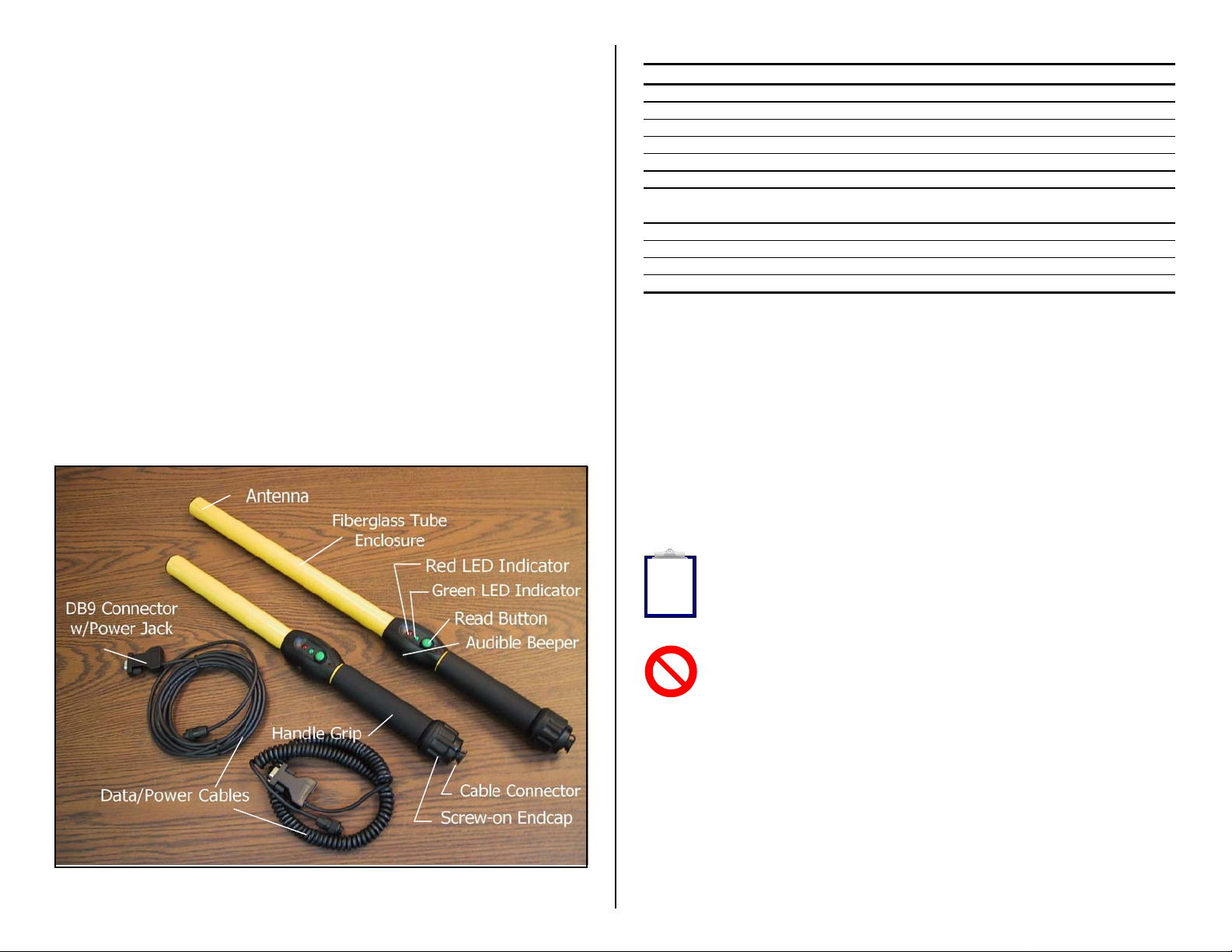
Figure 1 below illustrates the Stick Reader’s features that comprise the user interface
and that are pertinent to its operation. Each feature and its corresponding functional
description is described in Table 1.
Figure 1 - Stick Reader Features and User Interface
Table 1 - Stick Reader Features and Descriptions of Use
Feature Description of Use
Antenna 1 Emits activation signal and receives transponder signal
Red LED Indicator Illuminates whenever antenna is emitting activation signal
Green LED Indicator Illuminates whenever a transponder has been read
Audible Beeper 1 Beeps once on first transponder reading and twice for repeat
Read Button Applies power and activates exciter signal for reading transponder
Data/Power Cable Conveys power to Reader and serial data to and from Reader
DB9 Connector w/
DC Power Jack
Fiberglass Tube Rugged, watertight enclosure
Screw-on Endcap Provides access to battery compartment
Handle Grip Rubber anti-slip gripping surface
Cable Connector Electrical interface for attaching Data/Power Cable
1
Item is internal to enclosure and cannot be seen
Connects serial data to PC or data logger RS232 port
Accepts 6 to 12 VDC input as Reader power source
Power Source Requirements
The RS320-V2 Stick Reader contains a rechargeable and removable 9.6 VDC NiMH
Battery Pack, which serves as its primary power source. The RS320-V2 can also be
powered from its external AC Adapter/Charger, or from any external DC power
source rated between 9 VDC and 12 VDC with at least 1 ampere current capability.
Internal 9.6 VDC Battery Pack - Prior to operating the RS320-V2 Stick Reader
from its integral Battery Pack, the Battery Pack must be charged. This can be
accomplished by either of two methods: (1) install the Battery Pack into the Stick
Reader, attach the Data/Power Cable, and connect the AC Adapter to the DC input
jack located on the DB9 connector, or (2) install the Battery Pack into the Allflex
Model AK320 Fast Charger.
Note 1 - Battery Pack charging using the AC Adapter/Charger applies a slowcharge, which requires approximately 12 hours to complete. During this slowcharge cycle, the Stick Reader can be simultaneously operated from the AC
i
Adapter. The AK320 Fast Charger provides 2 hour charging of up to 3 Battery
Packs, simultaneously.
Note 2 - The RS320-V2 Stick Reader is designed to operate only with the
Battery Pack provided. The RS320-V2 will not operate with individual battery
cells of either disposable or rechargeable variety.
AC Adapter - The RS320-V2 Stick Reader can be powered using its AC
Adapter/Charger regardless of the charge state of the Battery Pack. The AC Adapter
can be used as a power source even if the Battery Pack has been removed from the
Stick Reader. If the AC Adapter has been connected, the user may proceed with
configuration and performance testing while the Battery Pack is charging.
Other External DC Power Sources - The Stick Reader can be powered external
DC power sources, such as 12 VDC vehicle batteries, or from the Allflex
1
PW50/PW250 series Battery Pack units that are used with RS250 type Stick Readers.
External DC power sources can be connected through either the DB9 connector pins
2

9 (+) and 5(-), or by using the 2.5mm coaxial jack located on the DB9 connector
(center conductor negative).
Note 3 - Certain weigh scales and other equipment to which the Stick Reader can
be attached provide DC power on pin 9 of the DB9 interface connector. Such DC
power sources are acceptable as long as the voltage is between 9 and 12 volts DC,
i
and are capable of providing at least 1.0 ampere continuous current. Pin 5 of the
DB9 connector is ground.
Note 4 - When an external power source, such as the AC Adapter, is connected to
the DC Power Jack, inserting the plug causes electrical continuity to pin 9 of the
i
DB9 connector to be interrupted. Polarity on the DC Power Jack is sleeve + and
center pin -. The DC power plug specification is a 2.5mm x 5.5mm DC Coaxial
(9.5mm length). See Figure 3 for the wiring details of this connector.
Note 5 - The Stick Reader is protected against accidental reverse polarity voltage
application and will not be damaged by such.
i
Note 6 - The Stick Reader’s integral Battery Pack is affected by temperature. At
0°C (32°F), the Battery Pack will deliver only about half of its rated energy
!
capacity. At lower temperatures, the Battery Pack may deliver unsatisfactory
performance. When the RS320-V2 Stick Reader is used in low temperature
environments, connection to an external power source, such as the Allflex PW50 Battery Pack,
and placement of this external Battery Pack close to the user’s body, is recommended.
Note 7 - To ensure proper Battery Pack charging, charging should be conducted
only in an environment where the temperature is between 15°C and 30°C (60°F
!
to 85°F). Charging at temperatures outside these boundaries will result in
unsatisfactory charge acceptance by the Battery Pack. For more information
about the characteristics of rechargeable batteries, please see the white paper at
[http://www.national.com/appinfo/power/files/f19.pdf#page=10].
Activating the RS320-V2 Stick Reader
With the Battery Pack fully charged and installed, or with the AC Adapter con nected
by means of the Data/Power Cable, the Stick Reader is ready to be used . To turn on
the Stick Reader, press the green Read button, holding it down until the red and
green indicators light and extinguish, and until the beeper stops sounding (this is
about ¼ second duration).
Note 8 - Very brief presses of the Read button will cause the indicators to light
and the beeper to sound, but will not be sufficiently long to latch the Stick Reader
!
into its power on state. Be sure to hold the Read button down until the beeper
stops sounding.
3
Upon power-up, the Stick Reader’s LCD readout will appear as shown below:
0000 READY TO
READ
This power-on message is indicative that the Stick Reader’s internal ID Code
memory has been cleared, and that the Stick Reader is prepared to read new tags.
If the Reader has been previously used, and ther e are ID Codes stored in memory,
the LCD readout will resemble the display shown below:
0012 HDX ISO:
982 000006975374
In this display, the 4 digits on the left side of the top line indicate the tag counter, and
the information on the right side of the top line d isplays the tag type. On the bo ttom
line appears the 3 digit ISO Country Code or Manufacturer Code, followed by the 12
digit decimal ISO National ID Code.
Display formats for other tags that can be read by the RS320-V2 Stick Reader are
shown below for ISO FDX-B and HDX Industrial coded tags.
0013 FDX-B ISO: 0014 HDX-I: 2048
982 009101723121 0000000000053925
Note 9 - Configurator® provides the capability to select the LCD readout ID
code format to (a) decimal or hexadecimal, (b) numeric or alpha country codes,
and (c) suppression or inclusion of ID code leading zeroes. Please see the section
i
on the Configurator® program beginning on page 12 of this User Manual.
Note 10 - Upon power-up, the LCD readout will always display the information
from the last tag read, unless the internal ID Code memory has been cleared. The
RS320-V2 Stick Reader does not have the capability to recall and display ID
i
codes from tags read prior to the last tag. For information about retrieving ID
Codes from memory and clearing the memory, please see the section titled
“Retrieving ID Codes Stored in Memory” which begins on page 15 of this User Manual.
Note 11 - The RS320-V2 Stick Reader is delivered with configuration options set
in the “default” state (see “Default Configuration” on pages 16-17.). Among these
default settings is the “Power On Read” option that determines the behavior of the
i
Stick Reader when the Read button is pressed. In the default “Don’t Read” state,
the power-on behavior is as described above. By changing this option setting to
“Read”, the Stick Reader will begin scanning for a tag immediately upon power-up, and will
not first enter the idle LCD readout states as illustrated above. This option and other Stick
Reader operational modes can be selected using the Configurator® program.
Note 12 - Each ID Code is stored internally in the Stick Reader’s non-volatile
memory until the user deliberately erases the stored ID codes after downloading
them into a recording device, such as a PC database. Up to 1638 ID codes can be
i
stored and retrieved later at the user’s convenience.
4

Note 13 - The Tag Counter feature on the LCD readout can be reset to zero at
any time by double clicking the Read button, and observing the LCD’s
enunciation “Reset Counter?”. Pressing the Read button again once while this
i
enunciation is on the LCD will force the Tag Counter to reset to the value “0000”.
Resetting the Tag Counter does not alter the ID codes previously read and stored
in the Stick Reader’s internal memory.
Note 14 - The Stick Reader provides a Null Memory Marker Code option that
inserts an all zeroes code number (Manufacturer Code and National ID Code)
i
whenever the Tag Counter is reset. This feature is easily enabled using the
Configurator® program’s “Memory Marker” option.
Note 15 - The Stick Reader can be optioned to process duplicate tag numbers in
either of two ways. In the default mode, any tag can be read, counted, and stored
multiple times whenever any other tag(s) is read interventionally. The Stick
i
Reader can also be optioned to check for duplicate tags within the most recent
number of tags as indicated by the Tag Counter, up to a maximum of 75 tags. In
this selected mode, a tag will always be read and displayed, but will be counted and stored
only if it has not been read within the last “n” tags where “n” is the Tag Counter indication,
and “n” is or less than or equal to 75. When a tag is read more than once in this mode, the ID
code is displayed, and the audible beeper provides a double beep indication, but it is not
counted again or stored again in memory, unless at least 75 other tags have been read and
stored in the interim. See “Counter Duplicate” in Stick Reader Configuration Options on
pages 11-14.
Reading Transponder Tags
The Stick Reader is always ready to read a transponder tag either immediately after
power has been activated (as is indicated by the presence of information on the LCD
readout), or from its off state (if the Power On Read option has been set to “Read” –
see Note 11). Initiating a tag reading event requires only a press of the Read button.
When the Read button is pressed and released, the tag activation signal is present for
a 3 second interval. Alternately, the Read button can be held down, and the
activation signal will remain on until the Read button is released, or until a tag is
read. The tag activation state is indicated by the red LED indicator illuminating.
When a tag is successfully read, the tag’s ID code information will appear on the
LCD readout, and for non-duplicate tag readings, the Tag Counter indication will
increment, and the ID code is automatically stored in the Stick Reader’s internal
memory. In addition, the Stick Reader’s green LED indicator will flash, and the
audible beeper will sound. A single flash/beep indication occurs the first time a tag
is read, and a double flash/beep indication occurs when a duplicate tag reading
occurs. (See Note 15 above for the option and definition of a duplicate tag read.)
Note 16 - The 3 second tag activation on signal interval can be configured for
times ranging between 1 second and 9 seconds, in 1 second increments, using
Configurator®. The default time interval is 3 seconds. See Configurator® option
i
“Read Time”
5
When the Read button is pressed, and the Stick Reader is activated to scan a tag, the
Red LED indicator flashes, and the LCD produces the indication as shown below:
( ( ID TAG ) )
( ( READING ) )
At the end of the tag scanning interval (which is the shorter of 3 seconds o r until a
tag is successfully read), the LCD readout either displays the ID code information
from the tag, or provides an indication that no tag was detected. These two displays
appear as follows:
DETECTED! 982 000003705995
In the event that no tag was detected, the above display indication lasts for about 3
seconds, and then the display reverts to display the tag ID code information from the
previously read ID tag.
The LCD readout contains a backlight that illuminates the display and makes it
easier to read tags in dimly lit environments. This backlight illuminates for an
interval of approximately 5 seconds upon initial powering of the Stick Read er, and
upon the successful reading of a tag. This illumination time is p urposefully limited
in order to conserve battery life.
As described in Note 13, the Tag Counter function can be reset to zero at any time by
double clicking the Read button while the Stick Reader is powered on and in its idle
mode. Upon double clicking the Read button, the LCD will produce the following
display indication:
> PRESS BUTTON
Pressing the Read Button again while this display indication is present will cau se the
Tag Counter to be reset to zero. If the Read button is not pressed during this
approximate 3 second period, the LCD display will revert to the previously read tag
indication, and the Tag Counter will remain at its previou s count total. Resettin g the
Tag Counter does not alter the contents of the ID Code Memory.
Note 17 - The Stick Reader can be configured to transmit tag data upon any one
of three possible conditions: (1) Send Repeats (the default setting); (2) Do not
i
send Repeats; and (3) Send Repeats upon Re-Read. See Configurator® option
“Send Duplicates”.
The LCD Readout
0009 NO ID TAG 0010 HDX ISO:
RESET COUNTER?

6
Read Range Performance
Figure 2 illustrates the read zone of the Stick Reader, within which tags can be
successfully detected and read. Optimum read distance occurs when the tag antenna
is aligned with the Stick Reader’s antenna as shown. When the tag is at the end of
the Stick Reader, optimum read distance coincides with a coaxial orientation of the
antennas, and when the tag is adjacent to the Stick Reader, optimum read distance
coincides with a planar orientation of the ant e nnas.
Figure 2 - Optimum Read Distance Tag Orientation
Stick Reader
Read Zone
Eartag
Antenna
Implant
Table 2 lists typical read distances that can be expected when reading different types
of Allflex eartags, in the optimum tag orientation at the end of the Stick Reader (as
shown in Figure 2).
Table 2 - Typical Read Distances for Various Allflex Eartags
Tag Type 9.6 VDC
(84 dBuV/m @10m)
HDX/HP Eartag 35 cm
HDX/LW Eartag 28 cm
FDX-B/HP Eartag 22 cm
FDX-B/LW Eartag 20 cm
Factors Affecting Read Range Performance
Tag readers are frequently assessed with respect to performance by their reading
distance. The read distance performance of the Stick Reader will be affected by the
following:
Transponder Orientation
reader antenna coils must be optimally oriented (see Figure 2).
- For maximum reading distance, the axes of the transponder and
Transponder Quality - Each manufacturer’s transponder differs in (a) the amount of exciter
signal energy necessary to sufficiently operate the transponder’s internal circuitry, and (b) the
signal level of the ID Code information that is returned to the reader. Consequently, it is
normal for transponders of a common type (FDX-B, for example) made by different
manufacturers to exhibit different read range performance characteristics.
Transponder Motion - Most portable readers have small antenna geometries, and
consequently produce small effective “read zones”. Portable readers are generally designed
for reading transponders under quasi-static conditions. Transponders that are moving quickly
past the reader may not be present within the reader’s read zone sufficiently long for all the ID
Code information to be obtained.
Transponder Size - Physically larger transponders generally contain larger receiving coils
which produce longer reading distances than smaller transponders.
Transponder Type - HDX transponders generally exhibit greater reading distances than FDXB transponders of comparable size.
Proximal Metallic Objects
attenuate and distort the electromagnetic fields generated in RFID systems, and thus diminish
read distance performance.
Electrical Noise Interference - RFID transponders and readers use electromagnetic signals as
a premise of operation. Other electromagnetic phenomena – radiated electrical noise from
computer displays, for example – can interfere with the transmission and reception of RFID
signals, and consequently reduce reading distance.
- Metal objects located near the transponder or Reader can
Transponder/Reader Interference - Multiple transponders within the sensing range of the
reader, or other readers emitting excitation energy in the immediate vicinity can adversely
affect the reading performance or prevent operation of the Stick Reader.
Depleted Battery Pack Charge - As the Battery Pack discharges, less energy becomes
available to generate the activation field, and this reduced field will result in a decreased read
range.
ID Code Memory
The Stick Reader contains an internal non-volatile memory capable of storing 1638
ID codes. ID codes are stored automatically upon being read. A transponder ID
code will not be stored multiple times if read multiple times successively, but can be
stored in memory multiple times if other tags are read in tervention ally. All ID codes
are retained when power to the Stick Reader is shut off. If more than 1638 ID cod es
are read, the new ID codes are written over the oldest ID codes in a wrap-around
manner.
ID Codes can be retrieved from the Stick Reader via its RS232 serial port by issuing
to the Reader the G command (see Table 5 on page 14). The G command can be
issued as many times as desired, and the complete memory contents will be
transferred upon each event. ID codes are not erased from the memory until the
C{Enter} command is received.
7
 Loading...