

Page 1
MADI
ACE
GLD-80
I/O Module MADI
T-112
iDR-48
iDR-48
UNDERSTANDING M-MADI
M-MADI is one of a range of option cards which can be fitted to an iLive to enable integration with other systems.
Multi-channel Digital Audio Interface (MADI) is an industry standard protocol for digital audio supported by many manufacturers.
Typically MADI is used for multi-channel recording and playback. Long coaxial cable runs are possible depending on the driver capability of
the hardware, making it a frequent choice of equipment interconnection in gigs, studios, and broadcast applications.
E.g. a 150m (490’) cable-run is reliable M-MADI to M-MADI using 75ohm Belden 1505A cable. MADI cables are directional, so there is one
connector for MADI-out, and one for MADI-in. It is a point-to point interface between a source and a destination.
M-MADI gives access to 64 input and 64 output channels and can be fitted
to:
Port B expansion slot in iLive fixed format MixRacks (iDR-16, iDR-
32, iDR-48 & iDR-64) or expander (xDR-16)
Port B and/or Port A of iLive modular MixRacks (iDR0, iDR10) if
fitted with the RAB-2 standard.
Port A of iLive modular Surfaces 80/112/144/176 if they are fitted
with the new RAB-2 standard.
I/O Module slot in GLD-80.
FEATURES at a glance
Dual link mode: connect and stream with two separate devices. Inputs to the system can be patched from the two MADI streams in blocks of
8, while the same outputs are broadcast on both links.
Redundant mode: Link 1 and Link 2 can be used as a redundant pair. Audio and clock will continue if one of the cables fails.
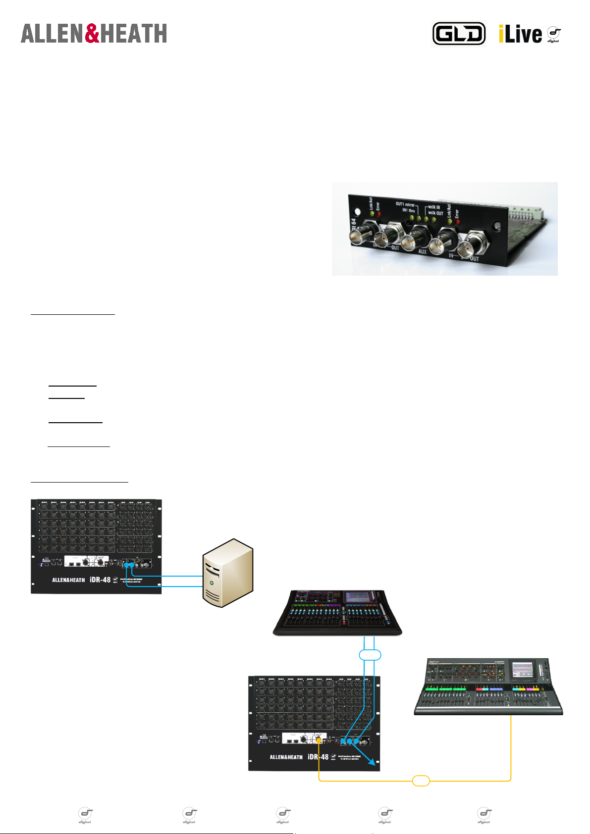
Aux BNC:
Out 1 mirror: This mode duplicates the MADI stream ‘Out 1’, useful for splitting signals to multiple devices.
In 1 Thru: The MADI stream ‘In 1’ is passed ‘thru’, allowing daisy chaining of signals to an unlimited number of devices. The signal is
fully reclocked and buffered for optimal reliability, and the signal will automatically switch to ‘In 2’ if ‘In 1’ fails in redundant mode.
WordClock IN: Provides a word clock input to sync the system from an external (48 KHz) source, for example a distributed word clock.
This is a high-sensitivity input, locking to a word clock signal as low as 200 mV p-p.
WordClock OUT: A standard word clock output to allow other systems to sync from the iLive system, useful when connecting to 3rd party
MADI devices which may not be able to sync from the MADI stream.
APPLICATION EXAMPLES
Record / playback <64 channels with a computer system, MADI audio
interface and suitable DAW.
M-MADI also provides BNC word clock connection to fixed format MixRacks
for external sync operations.
Here, M-MADI provides redundant digital split
linking between an iLive and a GLD system; <64
channels from the master MixRack are sent to the
Monitors system for independent processing. The
signals can also be sent to a record system or
third console via the Aux BNC connector.
digital notes digital notes digital notes digital notes digital notes digital notes
Page 2
MADI-2 in/out
MADI-1 in/out
MADI-Aux
MADI-Aux
TCP/IP
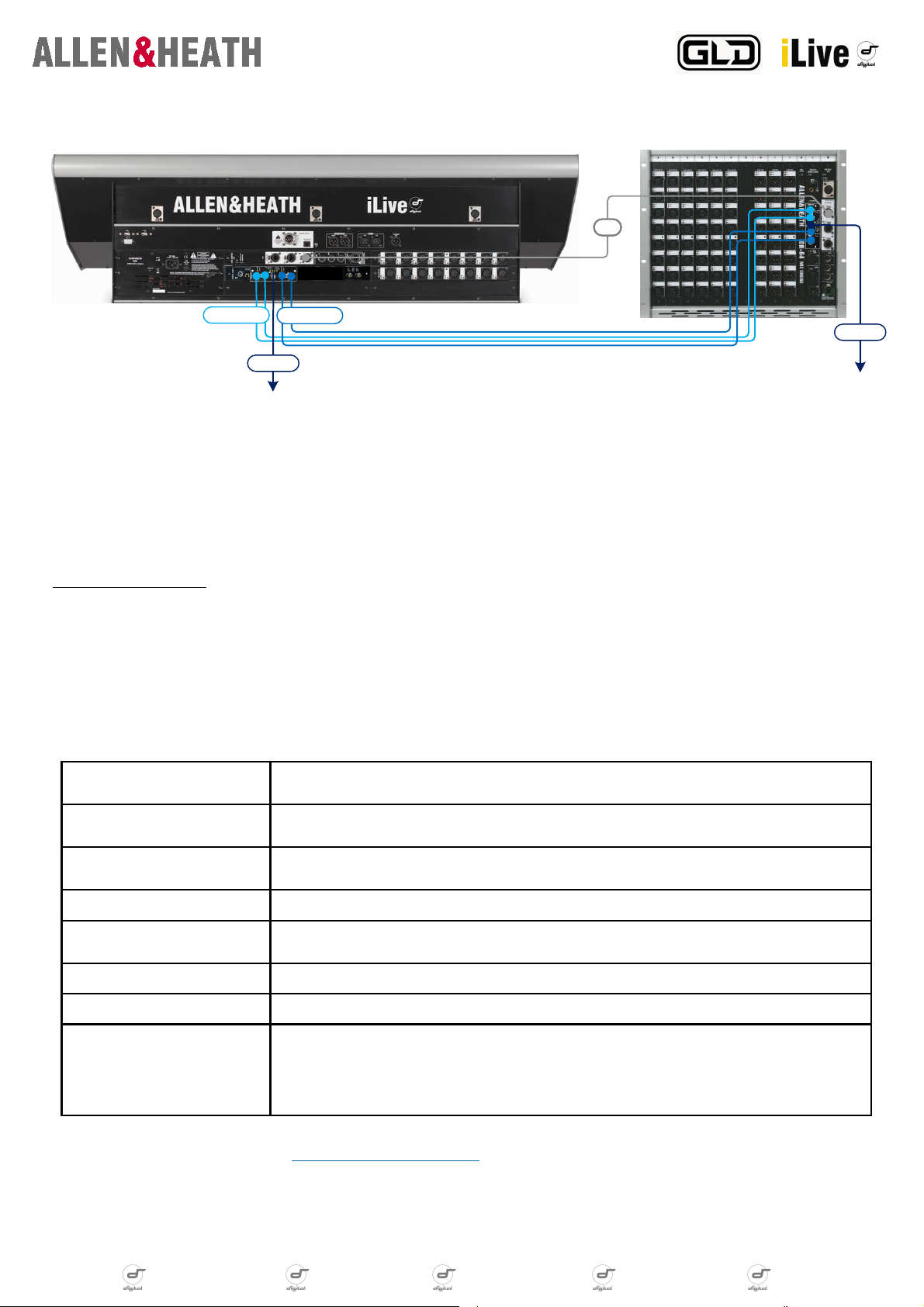
iLive Surface to MixRack audio link with redundancy plus 30 record feeds
Here M-MADI is used to form the two-way link between the iLive modular surface and the iDR10 MixRack. Both need to be fitted with RAB2
remote audio module and M-MADI option cards in Port-A. 4 cables are used: IN/OUT on Link 1, and IN/OUT on Link 2. Redundant mode is
chosen from the iLive touch-screen, this will ensure continuous audio signal and clock sync in the case of one link being broken. The AUX
BNC can be useful to provide some record feeds from the MixRack or Surface (ch1-32 are reserved for I/O at the surface, ch63/64 are PAFL).
Set the AUX BNCs to duplicate the signals present at the IN sockets of the surface M-MADI, and to mirror the OUT signals at the MixRack MMADI. Sources for the channels and AUX BNC can be configured in the Port-A tab on the OUTPUTS page of the touch-screen.
M-MADI SPECIFICATIONS
Ultra high-sensitivity inputs: An equalizing receiver circuit, originally designed for HD video, allows error-free reception of signals where a
normal receiver would not even detect that a signal is present. As a consequence, connecting two A&H MADI cards together allows cable
runs in excess of 150m
are also AC-coupled, to avoid potential ground loop problems.
Flexible Syncing: Users may select either of the input MADI streams (Link 1 or Link 2), or the ‘Aux’ BNC word clock input, when selected, as
the system clock source. Note that iLive is a 48 KHz system, and any selected clock sources must be 48 KHz
[1]
(triple the standard!), and electrical noise immunity is increased all round. All inputs, including the word clock input,
[2]
.
MADI Inputs x2 Ultra high-sensitivity equalizing receivers. 56 or 64 channels (auto detect), 24 bit.
(AC-coupled).
MADI Outputs x3 Standards compliant, low jitter transmitters. 64 channels, 24 bit. (Including ‘Aux’
BNC).
Word clock input High-sensitivity down to 200 mV peak-peak with 75R termination. (AC-coupled).
Word clock output 5V peak-peak through 75R source termination
[3]
.
Status indicators Per MADI Input: link/activity (yellow), Stream Error (red).
‘Aux’ BNC mode indicators (yellow).
Sync Sources MADI Link 1, MADI Link 2, Word clock (via ‘Aux’ BNC).
Audio Clock Sync range 48 KHz ±100ppm
Cable length
[1]
150m (A&H ↔ A&H)
[2]
150m (3rd party → A&H)
50-100m (3rd party ↔ A&H) (consult 3rd party documentation)
300m (A&H ↔ A&H, mains filters on both devices)
[1] Performance depends on cable type used. See http://www.ilive-digital.com/cables.html for cable recommendations.
[2] iDR-10 and iDR-0 users whose systems have been fitted with M-RAB2 may select a wider lock range; see the appropriate documentation for details.
[3] Word clock source termination can be turned off via a jumper setting to support some older devices with CMOS word clock inputs.
digital notes digital notes digital notes digital notes digital notes digital notes
Page 3

M-MADI FAQ
Q: What type of cable do I use with M-MADI and how far can it run?
A: Non-optical MADI systems use 75ohm Coaxial (video) cable terminated with BNC connectors. We tested M-MADI with typical industry cable
(Belden 1505A) with ‘Amphenol’ BNC connectors. We recommend the cables are professionally crimped using the correct tooling. When connecting two pieces of A&H MADI equipment, cable reach is extended from the standard 50m up to 150m with good quality cable. The key to
this feature is the receiver circuit in the MADI Option Card, so both ends of a MADI link must be A&H in order to achieve this distance. If audio
is only being transmitted to an A&H MADI card, with no audio being returned, cable length may also be extended. An RME MADI card transmitting audio to an A&H MADI card will work at 150m. Distances of between 150 and 300m will also work, but as MADI dictates that transformer
isolation is not used, these longer distances require the use of a mains filter or ‘cleaner’ for each device, if the link is to remain error free during high-voltage mains-line transients. Correct operation has been verified at 300m.
Treat coax cables with respect. Unlike touring-grade CAT5e cables, they are constructed using a solid core, which will break after repeated
bending. Ruggedised coax is available from manufacturers such as Belden, but this can be very expensive. See www.allen-heath.com for cable
recommendations.
Q: What sync options do I have with M-MADI and iLive/GLD?
A: Users can choose to take audio sync from the MADI Option Card. The normal ‘clock source’ drop-down on the touch screen or Editor pro-
gram will show ‘MixRack remote B’ (iLive) or ‘I/O Module’ (GLD), when fitted. M-MADI configuration panel has its own drop-down, for select-
ing to sync from either Link 1, Link 2, or Wordclock IN (useful in GLD and iLive fixed format systems where external sync connections are not
provided as standard). This selects which clock source is given to the system by the card.
The option to sync from the MADI stream in the mixer configuration page when a MADI Option Card is fitted is provided for convenience, and is
not part of the MADI spec. There should not be a problem with using this option, but it is outside of the spec.
When connecting Link 1 and Link 2 to two different devices, these devices must be in sync with each other, and with the iLive or GLD. This can
be achieved using a distributed word clock signal, or by syncing both devices from the MADI stream (i.e. from the MixRack), if they provide
this option. Making use of the Aux BNC as an additional word clock output can be useful here.
When using redundant mode, choosing either ‘Link 1’ or ‘Link 2’ sync merely sets the preferred input to sync from. If one link has failed, the
other will be switched to automatically.
Be careful with the AUX BNC. If the port is set to be a word clock output, and is connected to a MADI device from a 3rd party, the large output
swing of the word clock could in theory damage the MADI device. For this reason, the default setting for the AUX BNC is ‘Link 1 through‘; this
mode cannot damage anything.
When in non-redundant mode, altering the input routing may produce clicks or pops on the channels being switched. Changing this routing live
is not recommended.
Using an RME MADI card as the system clock master is possible. Make sure the RME MADI card ‘Clock Mode’ is set to ‘Master’, a nd that the
frequency is set within the system lock range (which varies depending on whether VCO mode has been activated or not). The simplest sync
method is then to set the A&H MADI card ‘Sync Source’ to ‘Link 1’, then set the ‘Audio Clock Source’ to ‘Mix Rack Remote B’ (iLive) or ‘I/O
Module’ (GLD).
An alternative is to connect the RME card WordClock Out to the A&H MADI card Aux BNC, set the ‘Mix Rack Aux BNC’ to ‘Word Clock In’, set
the ‘Audio Clock Source’ to ‘Mix Rack Remote B’ (iLive) or ‘I/O Module’ (GLD), then set MADI card ‘Sync Source’ to ‘WordClock Input’.
Word clock source termination can be bypassed by moving the jumper fitted to CN6 from pins 1-2 to pins 2-3. This could be required when
the Aux BNC is set to output WordClock, and the receiving device is an older device using a standard CMOS input stage. If a particular receiving device is not locking to the WordClock output, the first thing to try is to see if there is a ‘term’ switch on the receiving device, and turn it off.
If this does not work, try moving the MADI card jumper as described.
digital notes digital notes digital notes digital notes digital notes digital notes
Page 4

Q: iLive modular Surfaces can use the RAB2 audio system, this has two slots for options. Which can I use for MADI?
A: Port-A is used for the Surface-MixRack link. The only card supported in current firmware, that can be fitted to surface Port-B is M-MMO.
Typically M-MADI could be used for the iLive Surface to MixRack link and users may want to take advantage of the redundancy mode, where a
second set of cables (send and return) are connected to Link 2.
Q: Can I do recording from an iLive Surface M-MADI?
A: 32 channels in the MADI link are used for the I/O at the surface, plus others are used for PAFL and TB. However, channels 33-62 are freely
configurable in the Port-A tab on the touch-screen OUTPUTS page and Editor software. The M-MADI Aux BNC can be set to ‘repeat’ what is
coming in on Link 1. This way the AUX out can be used for recording at the surface location.
NB If not using redundant mode for a surface link, Link 2 on the surface port-A should not really be connected to anything. Its out port will be
transmitting the signals coming into any input cards fitted to the surface (channels 1-32), and the talkback mic signal (channel 63). Other channels will be silent. Since the ‘input routing’ in this case is forced to ‘all link 1’, its in port discards any stream connected to it.
Q: Can M-MADI be used with 56 channel systems?
A: The MADI card always transmits 64 channels. It can receive streams containing any number of channels up to 64. If the MADI stream being
provided to the card stops transmitting channels (i.e. it switches from a 64 channel mode to a 56 channel mode without interrupting the stream),
the system will see a constant DC level on these channels, until the cable connected to the ‘IN’ socket is disconnected, or the system is reset.
This is the case with an RME MADI card; switching from 64- to 56-channel mode with audio being received by the A&H MADI card on channels
57-64 will leave a DC level on these signals. Switching from 56- to 64-channel mode works without issue.
Q: Any tips about connecting multiple MADI devices?
A: Daisy chaining A&H MADI devices using ‘T’ connectors so that two or three cards receive the same channels should work when using shorter
cables, but should be discouraged. Users wishing to do this should perform their own experiments to make sure they are happy with the reliability of the system. A much better solution is to utilise the AUX BNC, and set its mode to ‘IN1 Through’; this allows 150m runs between devices.
A&H MADI card uses fully differential AC-Coupled inputs. This allows the system to operate with ground differences between connected units,
or, from another perspective, provides better fault tolerance in systems where there is a good common ground. This also means that it is not
possible to form a ground loop with a MADI cable.
Q: Which version of iLive / GLD firmware do I need before using M-MADI?
A: iLive firmware V1.53 or higher, GLD firmware V1.0 or higher. Note that some options are only enabled on GLD firmware V1.1 or higher.
Q: Does M-MADI work with RME and other third party devices?
A: Yes, we have tested M-MADI and it works well with RME devices, however we recommend you update RME devices to the latest version of
firmware. We have customers who have happily used M-MADI with Digico 56-channel MADI streams. M-MADI can provide multi-channel I/O via
SSL or Avid interfaces to ProTools.
digital notes digital notes digital notes digital notes digital notes digital notes
 Loading...