

Page 1

Installation Instructions
MP-Series Low-inertia Brushless
Servo Motors with 75 mm or Smaller
Frame Sizes
Catalog Numbers MPL-A1510, MPL-A1520, MPL-A1530, MPL-A210,
MPL-A220, MPL-A230, MPL-B1510, MPL-B1520, MPL-B1530, MPL-B210,
MPL-B220, MPL-B230
Topic Page
Important User Information 2
About This Publication 3
Catalog Number Explanation 3
Before You Begin 4
Installation and Maintenance Guidelines 4
Install the MPL Motors 10
MP-Series Low-inertia Servo Motors Dimensions 13
Motor Connectors 15
Load Force Capacities 16
Troubleshooting and Maintenance 17
Shaft Key Removal and Installation 17
Motor Cables and Accessory Kits 18
Specifications 19
Additional Resources 20
Page 2
2 MP-Series Low-inertia Brushless Servo Motors with 75 mm or Smaller Frame Sizes
Important User Information
Solid state equipment has operational characteristics differing from those of electromechanical equipment.
Safety Guidelines for the Application, Installation and Maintenance of Solid State Controls, publication
SGI-1.1
, available from your local Rockwell Automation sales office or online at
http://www.rockwellautomation.com/literature
equipment and hard-wired electromechanical devices. Because of this difference, and also because of the
wide variety of uses for solid state equipment, all persons responsible for applying this equipment must
satisfy themselves that each intended application of this equipment is acceptable.
In no event will Rockwell Automation, Inc. be responsible or liable for indirect or consequential damages
resulting from the use or application of this equipment.
The examples and diagrams in this manual are included solely for illustrative purposes. Because of the many
variables and requirements associated with any particular installation, Rockwell Automation, Inc. cannot
assume responsibility or liability for actual use based on the examples and diagrams.
No patent liability is assumed by Rockwell Automation, Inc. with respect to use of information, circuits,
equipment, or software described in this manual.
Reproduction of the contents of this manual, in whole or in part, without written permission of Rockwell
Automation, Inc., is prohibited.
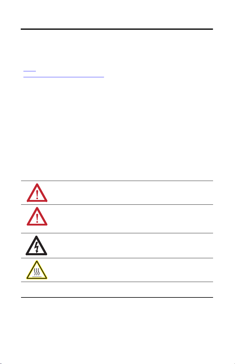
Throughout this manual, when necessary, we use notes to make you aware of safety considerations.
WARNING: Identifies information about practices or circumstances that
can cause an explosion in a hazardous environment, which may lead to
personal injury or death, property damage, or economic loss.
ATTENTION: Identifies information about practices or circumstances that
can lead to personal injury or death, property damage, or economic loss.
Attentions help you identify a hazard, avoid a hazard and recognize the
consequences.
, describes some important differences between solid state
SHOCK HAZARD: Labels may be on or inside the equipment, for example,
a drive or motor, to alert people that dangerous voltage may be present.
BURN HAZARD: Labels may be on or inside the equipment, for example, a
drive or motor, to alert people that surfaces may reach dangerous
temperatures.
IMPORTANT
Identifies information that is critical for successful application and
understanding of the product.
Publication MP-IN015A-EN-P - October 2010
Page 3

MP-Series Low-inertia Brushless Servo Motors with 75 mm or Smaller Frame Sizes 3
About This Publication
This publication provides installation instructions for the MP-Series low-inertia (Bulletin MPL)
motors with a frame size of 75 mm (2.95 in.) or smaller.
Use this document if you are responsible for installing these Allen-Bradley motor products.
Please read all instructions before installing this motor.
Catalog Number Explanation
MP L - B 2 10 V -
E J 7 2 A A
FACTORY DESIGNATED OPTIONS
A = Standard
MOUNTING FLANGE
A = IEC Metric
BRAKE
2=No Brake
4 = 24V DC Brake
CONNECTORS
7 = Circular DIN, Right Angle, 180° Rotatable
SHAFT KEY/SEAL
J = Shaft Key/No Shaft Seal
FEEDBACK
E = Single-turn High Resolution Encoder
H = 2000 Line Encoder
V = Multi-turn High Resolution Encoder
RATED SPEED
P = 5000 rpm
T = 6000 rpm
U = 7000 rpm
V = 8000 rpm
MAGNET STACK LENGTH DESIGNATOR
10
20
30
FRAME SIZE (IEC 72-1 FLANGE NUMBER)
15 = 63 mm (2.48 in.)
2 = 75 mm (2.95 in.)
VOLTAGE RATING
A = 230V AC
B = 460V AC
SERIES TYPE
L = Low-inertia
SERIES
Publication MP-IN015A-EN-P - October 2010
Page 4
4 MP-Series Low-inertia Brushless Servo Motors with 75 mm or Smaller Frame Sizes
Before You Begin
Remove all packing material, wedges, and braces from within and around the item. After
unpacking, verify the nameplate catalog number against the purchase order.
1. Remove the motor carefully from its shipping container.
2. Visually inspect the motor frame, mounting pilot, and connectors for damage.
3. Notify the carrier of any shipping damage immediately.
4. Retain the cardboard cover and protective paper sleeving from the mounting end of the
motor.
ATTENTION: Do not attempt to open and modify the motor.
Modifications that can be performed in the field are described in this manual.
Other changes should not be attempted.
Only a qualified Allen-Bradley employee can service this type of motor.
Failure to observe these safety procedures could result in personal injury or
damage to equipment.
Installation and Maintenance Guidelines
The guidelines in this section provide you with general information about installing servo
motors. Instructions specific to MPL servo motor installation follow this section.
To Prolong Motor Life
Thoughtful design and proper maintenance can increase the life of a servo motor. The following
are guidelines to maximize the life of a servo motor.
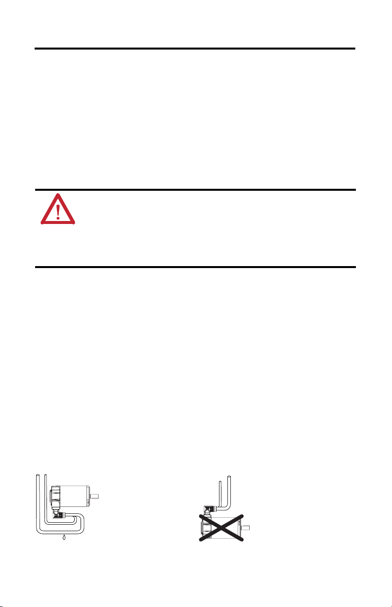
• Always install the motor with any cable entry point positioned underneath the motor
housing, and provide a drip loop in each cable. A drip loop is a downward bend in the
cable that lets water gather and drip off the cable rather than continue to flow along the
cable. These two installation practices greatly reduce the potential for moisture related
problems, and are depicted in the illustration.
Recommended Connector Orientation for Drip Loop
Cable enters beneath the
motor, and drip loop is formed.
• Avoid installing the motor with the shaft pointing upward, even if shaft seal in installed.
This orientation increases the risk of contaminant ingress.
Publication MP-IN015A-EN-P - October 2010
Motor is positioned so
cable enters from above.
Cable lacks drip loop.
Page 5

MP-Series Low-inertia Brushless Servo Motors with 75 mm or Smaller Frame Sizes 5
• Bearing contamination will shorten the life of a motor. The probability of this occurring
can be significantly reduced by installing a shaft seal. Ingress Protection Codes (IP
Ratings) for various mounting orientations are described in the Specifications section.
– A shaft seal is recommended whenever the motor shaft is exposed to moisture and
other fluids, including lubricating oil from a gearbox, or significant amounts of fine
dust.
– A shaft seal may be unnecessary if the motor shaft area is free of liquids or fine dust
and a lower IP rating will suffice.
• The brake on these motors are a permanent magnet-type holding brake. The brake
releases when voltage is applied. A separate 24V DC power source must be connected
with proper polarity to disengage the brake. This power source may be applied by a servo
motor controller, in addition to manual operator control.
If system main power fails, holding brakes can withstand occasional use as stopping
brakes. However, this is potentially damaging to the system, increases brake wear, and
reduces brake life.
IMPORTANT
Holding brakes are not designed to stop rotation of the motor shaft, nor are
they intended to be used as a safety device. They are designed to hold a motor
shaft at 0 rpm for up to the rated brake holding torque.
The recommended method of preventing motor shaft rotation is first, command
the servo drive to 0 rpm, second, verify the motor is at 0 rpm, third, engage the
brake, and finally, disable the drive.
Disabling the drive also removes the potential for brake wear caused by a badly
tuned servo system oscillating the shaft.
Mount the Motor
All MPL motors include a mounting pilot for aligning the motor on a machine. Preferred
fasteners are stainless steel. The installation must comply with all local regulations and use of
equipment and installation practices that promote electromagnetic compatibility and safety.
ATTENTION: Unmounted motors, disconnected mechanical couplings, loose
shaft keys, and disconnected cables are dangerous if power is applied.
Disassembled equipment should be appropriately identified (tagged-out) and
access to electrical power restricted (locked-out).
Before applying power to the motor, remove the shaft key and other mechanical
couplings that could be thrown from the shaft.
Failure to observe these safety procedures could result in personal injury.
The dimensions and dimensional symbols for the different frame sizes and stack lengths in the
MPL motors are referenced in the MP-Series Low-inertia Servo Motors Dimensions drawing
and tables.
Publication MP-IN015A-EN-P - October 2010
Page 6

6 MP-Series Low-inertia Brushless Servo Motors with 75 mm or Smaller Frame Sizes
Mechanical Connections
Mechanical connections to the motor shaft, such as couplings and pulleys, require a torsionally
rigid coupling or a reinforced timing belt. The high dynamic performance of servo motors can
cause couplings, pulleys, or belts to loosen or slip over time. A loose or slipping connection will
cause system instability and may damage the motor shaft. All connections between the machine
and the motor shaft must be rigid to achieve acceptable system response. Periodically inspect
connections to verify their rigidity.
ATTENTION: Do not strike the shaft, key, couplings, or pulleys with tools
during installation or removal.
Damage may occur to the motor bearings and the feedback device if sharp
impact to the shaft is applied during installation of couplings and pulleys, or a
shaft key. Damage to the feedback device also may result by applying leverage
from the faceplate to remove devices mounted on the motor shaft.
Apply a constant pressure, with a wheel puller for example, to the user end of
the shaft to remove a friction fit or a stuck device.
Failure to observe these safety procedures could result in damage to the motor
and its components.
When mounting couplings or pulleys to the shaft, verify that the connections are properly
aligned and that axial and radial loads are within the specifications of the motor.
Refer toLoad Force Capacities
motor bearing life.
A shaft key provides a rigid mechanical connection with the potential for self-alignment, but the
key must be properly installed in the keyway. Refer to MP-Series Low-inertia Servo Motors
Dimensions on page 13 for dimensional information about the key and shaft keyway.
Instructions for removing or installing a shaft key are provided in Shaft Key Removal and
Installation on page 17
on page 16 for guidelines on how to achieve 20,000 hours of
.
Connector Orientation
The housings for the feedback and power and brake connectors can be rotated once up to 180
degrees. This allows either connector to face down if the motor is installed in a vertical
application, rearward if connector access is restricted in a horizontal application, or to the side of
the motor.
ATTENTION: Connectors are designed to be rotated into a fixed position
during installation of the motor, and remain in that position without further
adjustment. Strictly limit the applied forces and the number of times the
connector is rotated to be sure that connectors meet the requirements of IP66.
Failure to observe these safety procedures could result in damage to the motor
and its components.
Publication MP-IN015A-EN-P - October 2010
Page 7

MP-Series Low-inertia Brushless Servo Motors with 75 mm or Smaller Frame Sizes 7
Rotate the connectors as follows.
1. Mount and fully seat a mating cable on the connector.
2. Grasp both connectors by their housings and slowly rotate them to the outside of the
motor.
If necessary, repeat this step for each connector (feedback or power/brake).
Apply force to only the connectors; do not apply force to the cable. No tools (for example, pliers
and vise-grips) should be used to assist with the rotation of the connector.
Interconnect Cables
Knowledgeable cable routing improves system electromagnetic compatibility (EMC). Refer
to Shield the Power Cable on page 8 for suggested grounding techniques.
To install cables properly, observe these guidelines.
• Do not connect feedback cable or power and brake cable while power is applied.
ATTENTION: Do not connect or disconnect the motor feedback cable, or the
power and brake cable while power is applied to them.
Inadvertent pin connections may result in unexpected motion or result in
irreversible damage to the components.
• Keep wire lengths as short as physically possible.
• Separate cables by 0.3 m (1 ft) minimum for every 9 m (30 ft) of parallel run.
• Route signa l cables that transmit encoder, seria l, or ana log data at low volta ges away from
the motor and power wiring.
• Ground both ends of the cable shield and twist the signal wire pairs to prevent
electromagnetic interference from other equipment.
ATTENTION: High voltage can be present on the shields of a power cable if
the shields are not grounded.
Verify there is a connection to ground for all shields in the power cable.
Failure to observe these safety procedures could result in personal injury or
damage to equipment.
Electrical Noise
Electromagnetic interference (EMI), commonly called noise, may adversely impact motor
performance by inducing stray signals. Effective techniques to counter EMI include filtering the
AC power, shielding and separating signal carrying lines, and practicing good grounding
techniques. Effective AC power filtering can be achieved by using isolated AC power
transformers or properly installed AC line filters.
Publication MP-IN015A-EN-P - October 2010
Page 8
8 MP-Series Low-inertia Brushless Servo Motors with 75 mm or Smaller Frame Sizes
To reduce EMI, observe these guidelines:
• Physically separate signal lines from motor cabling and power wiring. Do not route
signal wires with motor and power wires, and do not route signal wires over the vent
openings of servo drives or other electrical power sources.
• Ground all equipment using a single-point parallel ground system that employs ground
bus bars or large straps. If necessary, use additional electrical noise reduction techniques
to reduce EMI in noisy environments.
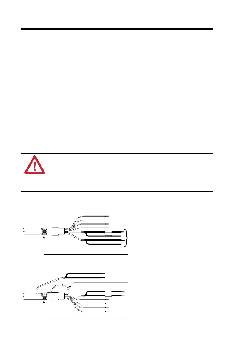
Shield the Power Cable
Shield the power cable as follows.
1. Verify the separate signal wire shield connects to the overall chassis ground by looping
back each of the signal wire pairs as shown in the diagram.
2. Clamp all three shields together at the power cable (chassis) ground connection on the
drive.
ATTENTION: High voltage can be present on the shields of a power cable, if
the shields are not grounded.
Verify there is a connection to ground for all shields in the power cable.
Failure to observe these safety procedures could result in personal injury or
damage to equipment.
Power Cable Shielding
Cable is factory supplied as follows.
Cable can be field modified as follows.
Publication MP-IN015A-EN-P - October 2010
Shielded Signal Wires (two) within Power Cable
Overall Power Cable Shield
Loop signal shield (one of two) to
overall power cable shield.
Power cable ground clamp on drive
should contact all (three) cable shields.
Page 9

MP-Series Low-inertia Brushless Servo Motors with 75 mm or Smaller Frame Sizes 9
Brake Control and Power Regulation
The DC power source for a permanent magnet brake, such as that on the MP-Series servo motor
with 75 mm (2.95 in.) or smaller frame, requires a DC power supply with low ripple voltage.
A motor brake requires relay contacts to open and remove power to the brake coil. Removing
power causes the brake to mechanically engage, but it also may cause electrical arcing to occur at
the contacts until the residual brake power sufficiently dissipates. A customer supplied diode is
recommended to prevent electrical arcing at the brake relay contacts. Substituting a metal oxide
varistor (MOV) for the diode can reduce the time to mechanically engage the brake. The
following diagram shows typical customer supplied components for brake control, including an
arc suppressing diode or MOV.
Arc Suppression in the Motor Brake Circuit
Brake Relay
Customer
Supplied
Components
DC Power Supply
+
-
Diode or MOV Arc Suppressor
The Kinetix 6000 and Kinetix 7000 drives from Rockwell Automation have a brake control relay
that includes a MOV arc suppressor. Customer supplied arc suppression is not required in this
case, unless power consumption by the brake requires an external brake relay.
Shaft Seals
An optional shaft seal may be installed on the motor shaft to protect the front bearing from
fluids or fine dust that could contaminate the motor bearing and reduce its lifetime. An IP66
rating for the motor depends on the usage of shaft seals and environmentally sealed
connectors/cables.
• Refer toSpecifications on page 19 for brief descriptions of IP ratings.
• Refer to the Kinetix Motion Control Selection Guide, publication GMC-SG001,
publication GMC-SG001
motor.
, to find the catalog numbers of seal kits available for your
Publication MP-IN015A-EN-P - October 2010
Page 10

10 MP-Series Low-inertia Brushless Servo Motors with 75 mm or Smaller Frame Sizes
Install the MPL Motors
Follow these steps to install an MPL motor.
ATTENTION: Do not strike the shaft, couplings, or pulleys with tools during
installation or removal.
Damage may occur to the motor bearings and the feedback device if sharp
impact to the shaft is applied during installation of couplings and pulleys.
Failure to observe these safety procedures could result in damage to the motor
and its components.
1. Allow sufficient clearances in the area of the motor for it to stay within its specified
operating temperature range.
Refer toSpecifications on page 19
Do not install the motor in an area with restricted airflow. Keep other heat producing
devices away from the motor.
To obtain the specified motor thermal rating , mount the motor so the heat dissipation is
at a minimum equivalent to the following surface.
For Motor Aluminum Heatsink Dimensions, Approx.
MPL-x15xx 203.2 x 203.2 x 6.35 mm (8 x 8 x 0.25 in.)
MPL-x2xx 254.0 x 254.0 x 6.35 mm (10 x 10 x 0.25 in.)
for the operating temperature range.
ATTENTION: Outer surfaces of the motor can reach high temperatures, 125 °C
(257 °F), during motor operation.
Take precautions to prevent accidental contact with hot surfaces. Consider motor
surface temperature when selecting motor mating connections and cables.
Failure to observe these safety procedures could result in personal injury or
damage to equipment.
2. Position the motor with the cable connections beneath the motor.
Refer toRecommended Connector Orientation for Drip Loop
reference of correct motor and cable positioning.
3. Properly mount and align the motor.
on page 4 for a visual
• All MPL motors include a mounting pilot for aligning the motor on a machine.
• The index pulse occurs on a 2000-line encoder when the shaft key is aligned with the
connectors.
• Make sure belt loading is within the motor limits, and all belts and pulleys are
properly aligned.
• Follow manufacturer recommendations for gearboxes, pulleys, or other motor
accessories.
Publication MP-IN015A-EN-P - October 2010
Page 11

MP-Series Low-inertia Brushless Servo Motors with 75 mm or Smaller Frame Sizes 11
4. Form a drip loop in the cables directly before each cable attaches to the motor.
Refer toRecommended Connector Orientation for Drip Loop
example.
ATTENTION: Be sure that cables are installed and restrained to prevent
uneven tension or flexing at the cable connectors.
Excessive and uneven lateral force at the cable connectors may result in the
connector’s environmental seal opening and closing as the cable flexes.
Failure to observe these safety procedures could result in damage to the motor
and its components.
5. Attach the feedback and the combination power and brake cables to the motor.
ATTENTION: Do not connect or disconnect the motor feedback cable, or the
power and brake cable while power is applied to them.
Inadvertent pin connections may result in unexpected motion or result in
irreversible damage to the components.
a. Carefully align each cable connector with the respective motor connector as shown
in Motor Connector Alignment
b. Do not apply excessive force when mating the cable and motor connectors. If the
connectors do not go together with light hand force, realign and try again.
6. Hand-tighten each collar as follows.
on page 12.
on page 4 for a visual
• One-quarter turn for a SpeedTec connector
• Five to six turns for a threaded connector
ATTENTION: Keyed connectors must be properly aligned and hand-tightened
the recommended number of turns.
Improper alignment is indicated by the need for excessive force, such as the
use of tools, to fully seat connectors.
Connectors must be fully tightened for connector seals to be effective.
Failure to observe these safety procedures could result in damage to the motor,
cables, and connector components.
Publication MP-IN015A-EN-P - October 2010
Page 12

12 MP-Series Low-inertia Brushless Servo Motors with 75 mm or Smaller Frame Sizes
Motor Connector Alignment
Connector plugs have a flat surface with
the Allen-Bradley name to indicate the
alignment point.
NOTE: Top of connector is relative to the
motor orientation.
Power/Brake Cables Motor Feedback Cables
Threaded (M4) Cable Plug Cat. No. SpeedTec (M7) Cable Plug Cat. No.
2090-xxNPMF-xxSxx 2090-CPxM7DF-xxAAxx
2090-xxNFMF-Sxx 2090-CFBM7Dx-CEAAxx
2090-CPxM4DF-16AFxx 2090-CPxM7DF-xxAFxx, 2090-CPBM7E7-xxAFxx
2090-CFBM4DF-CDAFxx 2090-CFBM7DF-CDAFxx, 2090-CFBM7E7-CDAFxx
ATTENTION: When installing threaded (M4) cable plugs, O-rings are required
on threaded DIN (M4) motor connectors for vibration protection.
Remove the O-ring from the SpeedTec DIN motor connector when installing
SpeedTec (M7) cable plugs.
Motors equipped with SpeedTec DIN connectors are fully compatible with
threaded (M4) cable plugs. Motors equipped with threaded DIN (M4) connectors
are compatible only with threaded (M4) cable plugs.
Publication MP-IN015A-EN-P - October 2010
Page 13

MP-Series Low-inertia Brushless Servo Motors with 75 mm or Smaller Frame Sizes 13
MP-Series Low-inertia Servo Motors Dimensions
AD
AB
HD
See Notes
Notes:
1. Connectors may rotate 180° outward once.
2. LD measures to rotational center of connectors.
3. LE measures to front of connector.
L
LE
LB
LA
LE
LD
Shaft Details
L-LB
T
D
S (Hole Dia.)
on
M (Bolt Dia.)
G
F
P
Shaft Key
MPL-x15xx = 3 x 3 x 14
MPL-x2xx = 4 x 4 x 16
MPL motors are designed to metric dimensions. Inch dimensions are mathematical conversions from millimeters.
Untoleranced dimensions are for reference.
The dimensions in the table are for non-brake motors. Footnotes provide the additional
dimensions for the brake option and tolerances for dimensions.
MP-Series Low-inertia Servo Motors Dimensions, Approx.
MPL-A
or
MPL-B
1510 53.9
AB
AD D
mm
mm
(in.)
(in.)
68.9
(2.12)
(2.71)
1520 146.2
1530 171.6
210 53.9
(2.12)
76.2
(3.00)
220 162.8
230 188.3
(1)
mm
(in.)
9.0
(0.3543)
11.0
(0.4331)
HD L
mm
(in.)
96.4
(3.80)
(2), (3)
mm
(in.)
133.2
(5.25)
(5.76)
(6.76)
111.2
137.3
(4.38)
(5.40)
(6.41)
(7.41)
(2)
L-LB
LA LB
mm
(in.)
19.7
(0.776)
22.7
(0.894)
mm
(in.)
9.0
(0.35)
9.0
(0.35)
mm
(in.)
113.5
(4.47)
126.5
(4.98)
151.9
(5.98)
114.6
(4.51)
140.1
(5.52)
165.6
(6.52)
(3)
LD
mm
(in.)
78.5
(3.09)
91.3
(3.60)
116.3
(4.58)
78.6
(3.09)
104.1
(4.10)
129.6
(5.10)
(3)
“N”
Pilot
Dia.
End of
Shaft
Threaded
Hole
(3)
LE
mm
(in.)
37.8
(1.49)
50.9
(2.00)
76.7
(2.98)
38.4
(1.51)
63.9
(2.52)
89.4
(3.52)
(1) Tolerance for this dimension is: MPL-x15xx +0.007, -0.002 (+0.0003, -0.0001), and MPL-x2xx +0.008, -0.003 (+0.0003, -0.0001).
(2) Tolerance for this dimension is ±0.7 (±.0.028).
(3) If ordering an MPL-x15xx motor with brake, add 36.1 mm 1.421 (in.) to L and LB, and 33.4 mm (1.32 in.) to LD and LE.
If ordering an MPL-x2xx motor with brake, add 39.0 mm (1.535 in.) to L and LB, and 24.7 mm (0.97 in.) to LD and LE.
Publication MP-IN015A-EN-P - October 2010
Page 14

14 MP-Series Low-inertia Brushless Servo Motors with 75 mm or Smaller Frame Sizes
MP-Series Low-inertia Servo Motors Dimensions, Approx.
MPL-A
or
MPL-B
M
N
mm (in.) mm (in.) mm (in.) mm (in.) mm (in.) mm (in.) mm (in.)
1510 63.0
1520
(2.480)
1530
210 75.0
220
(2.953)
230
(1) Tolerance for this dimension is: MPL-x15xx +0.011, -0.005 (+0.0004, -0.0002); and MPL-x2xx +0.012, -0.007 (+0.0005, -0.0003).
(2) Tolerance for this dimension is:
(3) Tolerance for this dimension is:
(4) Tolerance for this dimension is: +0.0, -0.1 (+0.0, -0.0004).
(5) Metric (M) threading dimensions include major diameter (mm) X thread pitch - tolerance class X thread depth in mm and (in.).
(1)
P S
40.0
(1.575)
60.0
(2.362)
55
(2.17)
70.0
(2.76)
(2)
T F
5.8
(0.228)
2.5
(0.098)
2.5
(0.098)
(3)
G
3.0
(0.118)
4.0
(0.157)
(4)
End of Shaft
7.2
(0.283)
8.5
(0.335)
MPL-x15xx and MPL-x2xx +0.3, -0.0 (+0.012, -0.0).
MPL-x15xx -0.004, -0.029 (-0.00016, -0.00114); and MPL-x2xx +0.0, -0.03 (+0.0, -0.0012).
(5)
M3 x 0.5 - 6H x
9.0 (0.35)
M4 x 0.7 - 6H x
10.0 (0.39)
Publication MP-IN015A-EN-P - October 2010
Page 15
MP-Series Low-inertia Brushless Servo Motors with 75 mm or Smaller Frame Sizes 15
B C
A
G
L
F
E
H
D
1
2
3
4
567
8
9
10
11
12
13
14
17
15
16
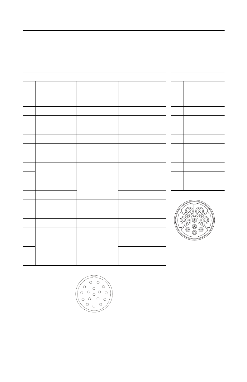
Motor Connectors
The tables below contain connector pin descriptions for the feedback and the combined power
and brake connectors.
Feedback Power and Brake
Pin High Resolution
Encoder
MPL-Axxx (230V) MPL-Bxxx (460V) MPL-A/Bxxxx-Hxxxx
1 Sin+ Sin+ AM+ A Phase U
2 Sin- Sin- AM- B Phase V
3 Cos+ Cos+ BM+ C Phase W
4 Cos- Cos- BM- D Ground
5 Data+ Data+ IM+ E Reserved
6 Data- Data- IM- F MBR+
7 Reserved Reserved Reserved G MBR8HReserved
9 EPWR 5V EPWR 5V L
10 ECOM ECOM
11 Reserved EPWR 9V Reserved
12 ECOM
13 TS+ TS+ TS+
14 TS- TS- TS15 Reserved Reserved S1
16 S2
17 S3
High Resolution
Encoder
Incremental Encoder Pin MPL-Axxx and
MPL-Bxxx
(1)
(1)
(1)
Intercontec P/N
BEDC091NN0000021700
(1) The U, V, and W power phases may be labelled as R, S, and T respectively.
Intercontec P/N
AEDC13NN00000222000
Publication MP-IN015A-EN-P - October 2010
Page 16

16 MP-Series Low-inertia Brushless Servo Motors with 75 mm or Smaller Frame Sizes
Load Force Capacities
Motors are capable of operating with a sustained shaft load. The location of the radial and axial
load force is shown in the figure, and maximum values are listed.
Loads are measured in pounds. Kilograms are mathematical conversions.
Load Forces on Shaft
Radial Load Force - Applied at center of shaft extension.
Axial Load Force
The following tables represent 20,000 hour L10-bearing fatigue life at various loads and speeds.
This 20,000 hour life does not account for possible application-specific life reduction that may
occur due to bearing grease contamination from external sources.
Radial Load Force Ratings
Motor 1000 rpm 2000 rpm 3500 rpm 4000 rpm at Max Speed
kg (lb) kg (lb) kg (lb) kg (lb) kg (lb) rpm
MPL-A/B1510 24 (53) 19 (42) — — 15 (33) 12 (26) 8000
MPL-A/B1520 25 (55) 20 (44) — — 16 (35) 14 (31) 7000
MPL-A/B1530 28 (62) 22 (49) — — 18 (40) 15 (33) 7000
MPL-A/B210 24 (53) 19 (42) — — 15 (33) 12 (26) 8000
MPL-A/B220 27 (60) 21 (46) 18 (40) — — 15 (33) 6000
MPL-A/B230 29 (64) 23 (51) 19 (42) — — 17 (37) 5000
Axial Load Force Ratings with Maximum Radial Load
Motor 1000 rpm 2000 rpm 3500 rpm 4000 rpm at Max Speed
kg (lb) kg (lb) kg (lb) kg (lb) kg (lb) rpm
MPL-A/B1510 15 (33) 10 (22) — — 7 (15) 5 (11) 8000
MPL-A/B1520 14 (31) 10 (22) — — 6 (13) 4 (9) 7000
MPL-A/B1530 13 (29) 9 (20) — — 6 (13) 4 (9) 7000
MPL-A/B210 15 (33) 10 (22) — — 7 (15) 5 (11) 8000
MPL-A/B220 14 (31) 9 (20) 7 (15) — — 5 (11) 6000
MPL-A/B230 13 (29) 9 (20) 6 (13) — — 5 (11) 5000
Publication MP-IN015A-EN-P - October 2010
Page 17

MP-Series Low-inertia Brushless Servo Motors with 75 mm or Smaller Frame Sizes 17
Axial Load Force Ratings with Zero Radial Load
Motor 1000 rpm 2000 rpm 3500 rpm 4000 rpm at Max Speed
kg (lb) kg (lb) kg (lb) kg (lb) kg (lb) rpm
MPL-A/B1510 24 (53) 17 (37) — — 12 (26) 8 (18) 8000
MPL-A/B1520 24 (53) 17 (37) — — 12 (26) 9 (20) 7000
MPL-A/B1530 24 (53) 17 (37) — — 12 (26) 9 (20) 7000
MPL-A/B210 24 (53) 17 (37) — — 12 (26) 8 (18) 8000
MPL-A/B220 24 (53) 17 (37) 13 (29) — — 10 (22) 6000
MPL-A/B230 24 (53) 17 (37) 13 (29) — — 10 (22) 5000
Troubleshooting and Maintenance
Standard troubleshooting and maintenance for this motor includes the following activities.
ATTENTION: Do not strike the shaft, key, couplings, or pulleys with tools
during installation or removal of any device.
Damage may occur to the motor bearings and the feedback device if sharp
impact to the shaft is applied during installation of couplings and pulleys, or
a shaft key. Damage to the feedback device also may result by applying
leverage from the faceplate to remove devices mounted on the motor shaft.
Apply a constant pressure, with a wheel puller, to the user end of the shaft
to remove any friction fit or stuck device from the motor shaft.
Failure to observe these safety procedures could result in damage to the
motor and its components.
Shaft Key Removal and Installation
Shaft keys are toleranced for an interference fit (slightly larger than the opening) to provide a
secure and rigid fit for the mating connection.
To Remove a Shaft Key
Lif t the key by grasping it with a plier or similar tool, or lever the ke y with a flat-blade screwdriver
inserted between the key and the slot.
To Install a Shaft Key
1. Verify the replacement key matches the keyway in the shaft and the mating mechanical
connection (for example, a coupling or pulley) before proceeding.
Publication MP-IN015A-EN-P - October 2010
Page 18

18 MP-Series Low-inertia Brushless Servo Motors with 75 mm or Smaller Frame Sizes
2. Support the motor shaft to prevent movement and to avoid motor bearing damage.
3.
Align the front of the key with the front of the motor shaft. This prevents a radiused
end-of-cut at the motor end of the keyway from interfering with correct seating of the key.
4. Apply a constant force across the exposed surface of the key with a controlled press
device (for example, a screw clamp) to push the key into the shaft.
Shaft Key Installation
Apply a constant force evenly
across the top of the key.
A
Support for
Motor Shaft
Radius Cut in Motor Shaft
Key
Motor Shaft
End of key
must align
with end of
motor shaft.
Detail A
Motor Cables and Accessory Kits
Accessories available from the factory include motor cables and shaft seals.
Motor Cables
Factory manufactured feedback and power cables are available in standard cable lengths. They
provide the sealing needed to achieve environmental ratings and shield termination.
Refer to the Kinetix Motion Control Selection Guide, publication GMC-SG001
numbers of cables appropriate for these motors.
Shaft Seals
Shaft seals provide environmental sealing of MPL motors. Shaft seals provide an additional
barrier to moisture and particle intrusion to the motor bearings. Motors are shipped without a
shaft seal, but this option is easily installed or replaced in the field.
MPL shaft seals have a Nitrile contact surface. Shaft seals require a lubricant provided in the kit.
, for the catalog
Shaft Seal Dimensions, Approx.
Motor Catalog No. Inside Diameter Outside Diameter Width
MPL-x15xx or MPL-x2xx MPL-SSN-F63/F75 12.0 mm (0.47 in.) 24.0 mm (0.95 in.) 7.0 mm (0.28 in.)
Refer to the Shaft Seal Installation Instructions, publication 2090-IN012, publication
2090-IN012
Publication MP-IN015A-EN-P - October 2010
, for detailed installation instructions.
Page 19

MP-Series Low-inertia Brushless Servo Motors with 75 mm or Smaller Frame Sizes 19
Specifications
Always store a motor in a clean and dry location within these environmental conditions.
Appropriate mounting, cabling, and a shaft seal may be required to attain a specific IP rating.
Exterior surfaces of the MP-Series small frame servo motors are made from these materials.
MP-Series Low-inertia Motors with 75 mm or Smaller Frame Size
Attribute Value
Temperature, Operating 0…40 °C (32…104 °F)
Temperature, Storage -30…70 °C (-22…158 °F)
Relative Humidity 5…95% noncondensing
Atmosphere Noncorrosive
Shock 20 g peak, 6 ms duration
Vibration 2.5 g, 30…2000 Hz
(1) (2)
Ingress Protection Codes
IP50 Motor without a shaft seal, mounted in the shaft up direction
IP51 Motor without a shaft seal, mounted in the shaft horizontal direction
IP53 Motor without a shaft seal, mounted in the shaft down direction
(3)
IP66
Material by Location
Housing Aluminum
Shaft 39NiCrMo3 or 1144 steel
Shaft Key Carbon steel
(1) IP ratings are determined using Rockwell Automation cables to connect to the motor.
(2) IP rating applies to a motor mounted as described.
(3) This rating is for dust tightness and powerful water jets ejecting water, not cleaning agents.
Motor with an optional shaft seal
(respectively per UNI7845 or ASTM-A311 Class B)
Publication MP-IN015A-EN-P - October 2010
Page 20
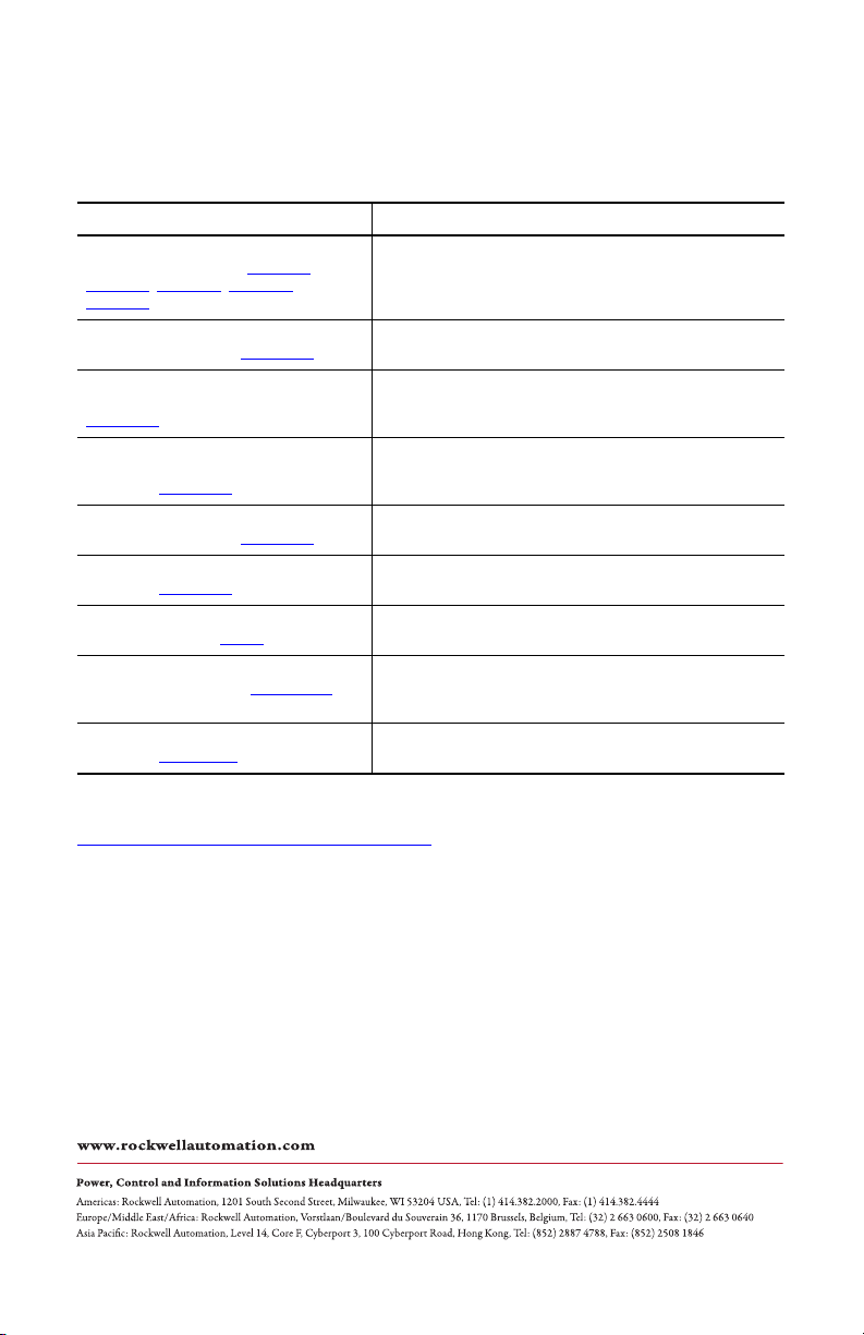
Additional Resources
For additional information about motors and compatible Rockwell Automation drives, refer to
these publications.
Resource Description
MPL-Series Brushless Motor Installation
Instructions, publications MP-IN001,
MP-IN002
, MP-IN003, MP-IN004, and
MP-IN005
Ultra3000 Digital Servo Drives Installation
Instructions, publication 2098-IN003
Ultra5000 Intelligent Positioning Drives
Installation Instructions, publication
2098-IN001
Kinetix 6000 Integrated Axis Modules and
Axis Modules Installation Instructions,
publication 2094-IN001
1394 SERCOS Drive Installation
Instructions, publication 1394-IN002
Shaft Seal Installation Instructions,
publication 2090-IN012
Rockwell Automation Industrial Automation
Glossary, publication AG-7.1
System Design for Control of Electrical
Noise Reference Manual, GMC-RM001
Kinetix Motion Control Selection Guide,
publication GMC-SG001
Provides information on installing MP-Series motors and
connecting the appropriate cables.
Provides information for designing, installing, and wiring an
Ultra3000 Digital Servo Drive.
Provides information for designing, installing, programming,
and troubleshooting the Ultra5000 Intelligent Positioning
Drive.
Provides information for mounting, powering, and controlling
the Kinetix 6000 integrated axis module (IAM) and up to seven
axis modules (AM) on a Bulletin 2094 power rail.
Provides information for designing, installing, and wiring a
1394 SERCOS interface multi-axis motion control system.
Provides information for installing shaft-seal kits for MP-Series
low-inertia motors, TL-Series motors, and F-Series motors.
Provides a glossary of industrial automation terms and
abbreviations.
Provides an overview of the practices that minimize the
possibility of noise-related failures and that comply with noise
regulations.
Provides an overview of Allen-Bradley motion controls and
systems including information about Kinetix and other motors.
These publications are available from your local Rockwell Automation office. At the website
http://www.rockwellautomation.com/literature you may download an electronic version of
these publications.
Allen-Bradley, Kinetix, Rockwell Software, Rockwell Automation, TechConnect, Ultra3000, and Ultra5000 are trademarks of Rockwell
Automation, Inc.
Trademarks not belonging to Rockwell Automation are property of their respective companies.
Rockwell Otomasyon Ticaret A.Ş., Kar Plaza İş Merkezi E Blok Kat:6 34752 İçerenköy, İstanbul, Tel: +90 (216) 5698400
Publication MP-IN015A-EN-P - October 2010 PN-25666
Supersedes Publication XXXX-X.X.X - Month Year Copyright © 2010 Rockwell Automation, Inc. All rights reserved. Printed in the U.S.A.
 Loading...