

Page 1

DeviceNet
Modules in
Logix5000™
Control Systems
1734-ADN, 1734-ADNX, 1734-PDN,
1756-DNB, 1769-SDN, 1784-PCIDS,
1788-CN2DN, 1788-DNBO,
1788-EN2DN, 1794-ADN
User Manual
Page 2
Important User Information
Solid state equipment has operational characteristics differing from those of
electromechanical equipment. Safety Guidelines for the Application,
Installation and Maintenance of Solid State Controls (Publication SGI-1.1
available from your local Rockwell Automation sales office or online at
http://www.ab.com/manuals/gi) describes some important differences
between solid state equipment and hard-wired electromechanical devices.
Because of this difference, and also because of the wide variety of uses for
solid state equipment, all persons responsible for applying this equipment
must satisfy themselves that each intended application of this equipment is
acceptable.
In no event will Rockwell Automation, Inc. be responsible or liable for
indirect or consequential damages resulting from the use or application of
this equipment.
The examples and diagrams in this manual are included solely for illustrative
purposes. Because of the many variables and requirements associated with
any particular installation, Rockwell Automation, Inc. cannot assume
responsibility or liability for actual use based on the examples and diagrams.
No patent liability is assumed by Rockwell Automation, Inc. with respect to
use of information, circuits, equipment, or software described in this manual.
Reproduction of the contents of this manual, in whole or in part, without
written permission of Rockwell Automation, Inc. is prohibited.
Throughout this manual we use notes to make you aware of safety
considerations.
WARNING
IMPORTANT
ATTENTION
SHOCK HAZARD
BURN HAZARD
Identifies information about practices or circumstances
that can cause an explosion in a hazardous environment,
which may lead to personal injury or death, property
damage, or economic loss.
Identifies information that is critical for successful
application and understanding of the product.
Identifies information about practices or circumstances
that can lead to personal injury or death, property
damage, or economic loss. Attentions help you:
• identify a hazard
• avoid a hazard
• recognize the consequence
Labels may be located on or inside the drive to alert
people that dangerous voltage may be present.
Labels may be located on or inside the drive to alert
people that surfaces may be dangerous temperatures.
Page 3

Preface
About This Manual
To: See :
get started with a Logix5000 controller DeviceNet Modules in Logix5000™ Control Systems, publication
Look up abbreviated information and procedures
regarding programming languages, instructions,
communications, and status
program a Logix5000 controller—detailed and
comprehensive information
program a specific Logix5000 programming
instruction
import or export a Logix5000 project or tags from or
to a text file
convert a PLC-5 or SLC 500 application to a
Logix5000 project
control devices over an EtherNet/IP network EtherNet/IP Modules in Logix5000 Control Systems User
control devices over an ControlNet™ network ControlNet Modules in Logix5000 Control Systems User Manual,
You are
here
control devices over an DeviceNet™ network DeviceNet Modules in Logix5000 Control Systems User Manual,
The manual is one of various Logix5000 manuals.
1756-QS001
Logix5000 Controllers System Reference, publication
1756-QR007
Logix5000 Controllers Common Procedures, publication
1756-PM001
• Logix5000 Controllers General Instructions Reference
Manual, publication 1756-RM003
• Logix5000 Controllers Process and Drives Instructions
Reference Manual, publication 1756-RM006
• Logix5000 Controllers Motion Instruction Set Reference
Manual, publication 1756-RM007
Logix5000 Controllers Import/Export Reference Manual,
publication 1756-RM084
Logix5550 Controller Converting PLC-5 or SLC 500 Logic to
Logix5550 Logic Reference Manual, publication 1756-6.8.5
Manual, publication ENET-UM001
publication CNET-UM001
publication DNET-UM004
This manual guides the development of a control system that uses a
Logix5000™ controller and a DeviceNet™ network. A Logix5000
controller is any of the following:
• 1756 ControlLogix® controllers
• 1769 CompactLogix™ controllers
• 1789 SoftLogix5800™ controllers
• 1794 FlexLogix™ controllers
• PoweFlex®700S with DriveLogix™ controllers
1 Publication DNET-UM004A-EN-P - March 2004
Page 4

Preface 2
Who Should Use this
This manual is for those who program or maintain industrial
automation systems.
Manual
To use this manual, you must already have experience with:
• programmable controllers
• industrial automation systems
• personal computers and Windows® 95, Windows 98,
Windows NT®, or Windows 2000 operating system
Conventions in this Manual
Text that is: Identifies: For example: Means:
Italic the actual name of an item that you
see on your screen or in an example
courier information that you must supply
based on your application (a
variable)
enclosed in brackets a keyboard key Press [Enter]. Press the Enter key.
As you use this manual, you will see some terms that are formatted
differently from the rest of the text:
Right-click User-Defined … Right-click on the item that is named
User-Defined.
Right-click
name_of_program …
You must identify the specific program in
your application. Typically, it is a name or
variable that you have defined.
Publication DNET-UM004A-EN-P - March 2004
Page 5

Before You Begin
Configure Your Network Offline
Table of Contents
Chapter 1
What This Manual Covers . . . . . . . . . . . . . . . . . . . . . . . . . 1-1
Preliminary Actions . . . . . . . . . . . . . . . . . . . . . . . . . . . . . . 1-3
Choose a Scanner . . . . . . . . . . . . . . . . . . . . . . . . . . . . . . . 1-5
Bridging Across Networks . . . . . . . . . . . . . . . . . . . . . . . . . 1-6
Choose a Baud Rate for the Network . . . . . . . . . . . . . . . . . 1-9
If You Want to Use a Higher Baud Rate… . . . . . . . . . . 1-10
Calculate Scanner Memory Requirements . . . . . . . . . . . . . . 1-11
Check the I/O Limits of the Scanner . . . . . . . . . . . . . . . 1-11
If You Are Using a SoftLogix5800 Controller . . . . . . . . . 1-12
Assign an Address to Each Device . . . . . . . . . . . . . . . . . . . 1-13
Chapter 2
How to Use This Chapter . . . . . . . . . . . . . . . . . . . . . . . . . 2-1
Before You Begin . . . . . . . . . . . . . . . . . . . . . . . . . . . . . . . 2-2
Create a File for the Network. . . . . . . . . . . . . . . . . . . . . . . 2-3
Create a DeviceNet Configuration File. . . . . . . . . . . . . . 2-3
Give the File a Descriptive Name . . . . . . . . . . . . . . . . . 2-3
Draw Your Network . . . . . . . . . . . . . . . . . . . . . . . . . . . . . 2-4
If Your Device Is Not in the Hardware List… . . . . . . . . 2-4
Configure Each Device . . . . . . . . . . . . . . . . . . . . . . . . . . . 2-5
Specify the Address of the Device. . . . . . . . . . . . . . . . . 2-6
Configure the Parameters of the Device . . . . . . . . . . . . 2-7
Configure the Scanner . . . . . . . . . . . . . . . . . . . . . . . . . . . . 2-8
Specify the Address of the Scanner . . . . . . . . . . . . . . . 2-9
Define the Properties of the Scanner. . . . . . . . . . . . . . . 2-10
Set the Alignment Option . . . . . . . . . . . . . . . . . . . . . . . 2-11
Clear or Set the Automap on Add Check Box . . . . . . . . 2-12
Build the Scan List . . . . . . . . . . . . . . . . . . . . . . . . . . . . 2-13
Manually Assign Each Device to a Memory Location . . . 2-14
Close the Configuration of the Scanner . . . . . . . . . . . . . 2-15
Save the Network File . . . . . . . . . . . . . . . . . . . . . . . . . . . . 2-15
Generate an RSNetWorx Report . . . . . . . . . . . . . . . . . . . . . 2-16
Download the Configuration to Network . . . . . . . . . . . . . . 2-17
Before You Download the Configuration . . . . . . . . . . . 2-17
Open the Configuration File for the Network . . . . . . . . 2-17
Go Online to the Network . . . . . . . . . . . . . . . . . . . . . . 2-18
Download the Configuration to the Network. . . . . . . . . 2-19
Chapter 3
Connect a Computer to the System
1 Publication DNET-UM004A-EN-P - March 2004
How to Use This Chapter . . . . . . . . . . . . . . . . . . . . . . . . . 3-1
Connect a Computer to a Network. . . . . . . . . . . . . . . . . . . 3-2
Configure a Driver for a Network . . . . . . . . . . . . . . . . . . . 3-3
Add the Driver. . . . . . . . . . . . . . . . . . . . . . . . . . . . . . . 3-3
Make Sure the Driver Works. . . . . . . . . . . . . . . . . . . . . 3-6
Page 6

Table of Contents 2
Automatically Configure a
DeviceNet Network
Chapter 4
How To Use This Chapter . . . . . . . . . . . . . . . . . . . . . . . . . 4-1
Determine If You Can Use AutoScan . . . . . . . . . . . . . . . . . 4-1
How AutoScan Effects Your Network. . . . . . . . . . . . . . . . . 4-2
Install the Node Commissioning Tool. . . . . . . . . . . . . . . . . 4-2
Connect Each Device to the Network. . . . . . . . . . . . . . . . . 4-3
Set the Address of a Scanner . . . . . . . . . . . . . . . . . . . . 4-4
Set the Address and Baud Rate of a Device Via Software 4-5
Add the Scanner to the RSLogix 5000 Project . . . . . . . . . . . 4-6
Add the Scanner to the I/O Configuration Folder . . . . . 4-6
Define the Properties of the Scanner. . . . . . . . . . . . . . . 4-7
Turn On AutoScan . . . . . . . . . . . . . . . . . . . . . . . . . . . . . . 4-7
Download the RSLogix 5000 Project and Go Online . . . 4-7
Turn On AutoScan . . . . . . . . . . . . . . . . . . . . . . . . . . . . 4-8
Access Device Data. . . . . . . . . . . . . . . . . . . . . . . . . . . . . . 4-9
Put the Scanner in Run Mode . . . . . . . . . . . . . . . . . . . . . . 4-11
Additional Information About AutoScan . . . . . . . . . . . . . . . 4-12
Type of Connection that the Scanner Sets Up . . . . . . . . 4-12
Allocating More Memory for Each Device . . . . . . . . . . . 4-12
Connect Each Device to the
Network
Configure Your Network Online
Chapter 5
Using This Chapter . . . . . . . . . . . . . . . . . . . . . . . . . . . . . . 5-1
Before You Begin . . . . . . . . . . . . . . . . . . . . . . . . . . . . . . . 5-1
Set the Address of a Device . . . . . . . . . . . . . . . . . . . . . . . . 5-2
Set an Address with Software. . . . . . . . . . . . . . . . . . . . . . . 5-3
Procedures for Specific Devices . . . . . . . . . . . . . . . . . . . . . 5-4
ControlLogix Scanner 1756-DNB. . . . . . . . . . . . . . . . . . 5-4
CompactLogix Scanner 1769-SDN . . . . . . . . . . . . . . . . . 5-4
ControlNet to DeviceNet Linking Device 1788-CN2DN 5-5
DriveLogix and FlexLogix Scanner 1788-DNBO . . . . . . . 5-5
EtherNet/IP to DeviceNet Linking Device 1788-EN2DN . 5-6
SoftLogix5800 Scanner 1784-PCIDS . . . . . . . . . . . . . . . . 5-10
Make Sure Your Devices Are on the Network. . . . . . . . . . . 5-11
Chapter 6
How to Use This Chapter . . . . . . . . . . . . . . . . . . . . . . . . . 6-1
Before You Begin . . . . . . . . . . . . . . . . . . . . . . . . . . . . . . . 6-2
Create a File for the Network. . . . . . . . . . . . . . . . . . . . . . . 6-3
Create a DeviceNet Configuration File. . . . . . . . . . . . . . 6-4
Give the File a Descriptive Name . . . . . . . . . . . . . . . . . 6-4
Go Online to the Network. . . . . . . . . . . . . . . . . . . . . . . . . 6-5
Configure Each Device . . . . . . . . . . . . . . . . . . . . . . . . . . . 6-6
Upload the Configuration of a Device. . . . . . . . . . . . . . 6-7
Change and Download Parameters . . . . . . . . . . . . . . . . 6-8
Configure the Scanner . . . . . . . . . . . . . . . . . . . . . . . . . . . . 6-9
Publication DNET-UM004A-EN-P - March 2004
Page 7

Control a Device
Table of Contents 3
Upload the Current Configuration of the Scanner . . . . . 6-10
Define the Properties of the Scanner. . . . . . . . . . . . . . . 6-11
Set the Alignment Option . . . . . . . . . . . . . . . . . . . . . . . 6-12
Clear or Set the Automap on Add Check Box . . . . . . . . 6-13
Build the Scan List . . . . . . . . . . . . . . . . . . . . . . . . . . . . 6-14
Manually Assign Each Device to a Memory Location . . . 6-15
Download the Configuration to the Scanner . . . . . . . . . 6-16
Upload and Save the Network File. . . . . . . . . . . . . . . . . . . 6-16
Generate an RSNetWorx Report . . . . . . . . . . . . . . . . . . . . . 6-17
Chapter 7
How to Use This Chapter . . . . . . . . . . . . . . . . . . . . . . . . . 7-1
Before You Use This Chapter . . . . . . . . . . . . . . . . . . . . . . 7-2
Add the Scanner to the I/O Configuration of the Controller 7-3
If You Need to Conserve EtherNet/IP or ControlNet Network
Bandwidth. . . . . . . . . . . . . . . . . . . . . . . . . . . . . . . . . . 7-3
Add the Scanner to the I/O Configuration Folder . . . . . 7-5
Define the Properties of the Scanner. . . . . . . . . . . . . . . 7-6
Determine the Address of DeviceNet Data . . . . . . . . . . . . . 7-7
If You Have a SoftLogix5800 Controller . . . . . . . . . . . . 7-9
Program Your Logic With Alias Tags . . . . . . . . . . . . . . . . . 7-10
Determine If a Device Has Failed . . . . . . . . . . . . . . . . . . . 7-11
Place the Scanner in Run Mode . . . . . . . . . . . . . . . . . . . . . 7-12
When to Use a MSG Instruction. . . . . . . . . . . . . . . . . . . . . 7-13
Determine the Parameter Number to Access. . . . . . . . . . . . 7-13
Determine the Configuration of the Parameter . . . . . . . . . . 7-14
Test the Parameter . . . . . . . . . . . . . . . . . . . . . . . . . . . . . . 7-15
Enter Message Logic . . . . . . . . . . . . . . . . . . . . . . . . . . . . . 7-16
Define the Source or Destination Data . . . . . . . . . . . . . 7-17
Enter and Configure the MSG Instruction . . . . . . . . . . . 7-18
Set the Communication Path. . . . . . . . . . . . . . . . . . . . . 7-19
Interlock and Share Inputs
Chapter 8
How to Use This Chapter . . . . . . . . . . . . . . . . . . . . . . . . . 8-1
Interlock. . . . . . . . . . . . . . . . . . . . . . . . . . . . . . . . . . . . . . 8-1
Choose a Master Controller . . . . . . . . . . . . . . . . . . . . . 8-2
Determine How Much Data to Exchange . . . . . . . . . . . 8-2
Enable Slave Mode for the Slave Scanner . . . . . . . . . . . 8-3
Map the Slave Mode Data. . . . . . . . . . . . . . . . . . . . . . . 8-4
Add the Slave to the Scan List of the Master . . . . . . . . . 8-4
Map the Data of the Slave . . . . . . . . . . . . . . . . . . . . . . 8-5
Place Both Scanners In Run Mode . . . . . . . . . . . . . . . . 8-5
Share Inputs . . . . . . . . . . . . . . . . . . . . . . . . . . . . . . . . . . . 8-5
Add the Input to the First Scanner . . . . . . . . . . . . . . . . 8-5
Add the Input to the Second Scanner . . . . . . . . . . . . . . 8-6
Publication DNET-UM004A-EN-P - March 2004
Page 8

Table of Contents 4
Communicate with a PanelView™
Standard Terminal
Map the Input Data in the Second Scanner . . . . . . . . . . 8-7
Chapter 9
Using This Chapter . . . . . . . . . . . . . . . . . . . . . . . . . . . . . . 9-1
Choose Data Types . . . . . . . . . . . . . . . . . . . . . . . . . . . . . . 9-1
Choose an Communication Method . . . . . . . . . . . . . . . . . . 9-2
I/O Slave Communication . . . . . . . . . . . . . . . . . . . . . . 9-2
Explicit Server Communication . . . . . . . . . . . . . . . . . . . 9-3
Explicit Client Communication . . . . . . . . . . . . . . . . . . . 9-3
Plan and Configure I/O Slave Tags . . . . . . . . . . . . . . . . . . 9-4
Use a Word/Bit Format for Each Tag . . . . . . . . . . . . . . 9-5
For Integers, Skip Every Other Word . . . . . . . . . . . . . . 9-5
Configure an I/O Slave Tag . . . . . . . . . . . . . . . . . . . . . 9-6
Set Up the Terminal on the Network . . . . . . . . . . . . . . . . . 9-7
Set the Protocol . . . . . . . . . . . . . . . . . . . . . . . . . . . . . . 9-7
Set the Network Address and I/O Sizes. . . . . . . . . . . . . 9-8
Configure the Scanner to Update I/O Slave Tags . . . . . . . . 9-9
Add the Terminal to the Scan List . . . . . . . . . . . . . . . . . 9-9
Edit I/O Parameters . . . . . . . . . . . . . . . . . . . . . . . . . . . 9-10
Map Input and Output Data . . . . . . . . . . . . . . . . . . . . . 9-10
Address I/O Slave Tags in the RSLogix 5000 Project . . . . . . 9-11
Plan and Configure Explicit Server Tags . . . . . . . . . . . . . . . 9-13
Assign Assembly Instances . . . . . . . . . . . . . . . . . . . . . . 9-13
For Integers, Skip Every Other Word . . . . . . . . . . . . . . 9-14
Configure an Explicit Server Tag. . . . . . . . . . . . . . . . . . 9-15
Program the Controller to Get/Set Explicit Server Tags . . . . 9-16
Create an Array for the Assembly Instance . . . . . . . . . . 9-16
Enter and Configure the MSG Instruction . . . . . . . . . . . 9-17
Set the Communication Path. . . . . . . . . . . . . . . . . . . . . 9-18
Configure Explicit Client Tags . . . . . . . . . . . . . . . . . . . . . . 9-19
Determine the Parameter Number to Access . . . . . . . . . 9-19
Determine the Configuration of the Parameter. . . . . . . . 9-20
Configure an Explicit Client Tag . . . . . . . . . . . . . . . . . . 9-21
Communicate with an RSView®
Project
Tune the Performance of a
DeviceNet Network
Publication DNET-UM004A-EN-P - March 2004
Chapter 10
Using This Chapter . . . . . . . . . . . . . . . . . . . . . . . . . . . . . . 10-1
Before You Use This Chapter . . . . . . . . . . . . . . . . . . . . . . 10-2
Create a Topic for the Device . . . . . . . . . . . . . . . . . . . . . . 10-3
Create a Node. . . . . . . . . . . . . . . . . . . . . . . . . . . . . . . . . . 10-4
Create a Tag for the Parameter . . . . . . . . . . . . . . . . . . . . . 10-5
Chapter 11
Using This Chapter . . . . . . . . . . . . . . . . . . . . . . . . . . . . . . 11-1
Factors that Effect Performance . . . . . . . . . . . . . . . . . . . . . 11-2
I/O Parameters of Each Device. . . . . . . . . . . . . . . . . . . 11-3
Page 9

Troubleshoot a DeviceNet
Network
Table of Contents 5
Background Poll . . . . . . . . . . . . . . . . . . . . . . . . . . . . . 11-3
Interscan Delay . . . . . . . . . . . . . . . . . . . . . . . . . . . . . . 11-4
Change the Configuration of the Network . . . . . . . . . . . . . 11-5
Upload the Current Configuration of the Scanner . . . . . 11-5
Set the Interscan Delay and Poll Ratio. . . . . . . . . . . . . . 11-6
Set the I/O Parameters of a Device . . . . . . . . . . . . . . . . 11-6
Download the Configuration to the Scanner . . . . . . . . . 11-8
Save the Network File . . . . . . . . . . . . . . . . . . . . . . . . . 11-9
Chapter 12
Using This Chapter . . . . . . . . . . . . . . . . . . . . . . . . . . . . . . 12-1
Front Display . . . . . . . . . . . . . . . . . . . . . . . . . . . . . . . . . . 12-1
CompactLogix Scanner 1769-SDN . . . . . . . . . . . . . . . . . 12-1
ControlLogix Scanner 1756-DNB. . . . . . . . . . . . . . . . . . 12-3
ControlNet to DeviceNet Linking Device 1788-CN2DN 12-5
DriveLogix and FlexLogix Scanner 1788-DNBO . . . . . . . 12-7
EtherNet/IP to DeviceNet Linking Device 1788-EN2DN . 12-8
SoftLogix5800 Scanner 1784-PCIDS . . . . . . . . . . . . . . . 12-11
Status Tags in the Controller . . . . . . . . . . . . . . . . . . . . . . 12-13
Status Register . . . . . . . . . . . . . . . . . . . . . . . . . . . . . . 12-14
Status Tags . . . . . . . . . . . . . . . . . . . . . . . . . . . . . . . . 12-15
Status Codes . . . . . . . . . . . . . . . . . . . . . . . . . . . . . . . . . . 12-16
Automate the Replacement of a
Failed Device
Using FLEX™ I/O Modules on a
DeviceNet Network
Chapter 13
How to Use This Chapter . . . . . . . . . . . . . . . . . . . . . . . . . 13-1
How to Automate the Replacement of a Failed Device . . . . 13-1
Set Up Automatic Device Recovery . . . . . . . . . . . . . . . . . . 13-3
Choose an Electronic Key Level for a Device . . . . . . . . 13-3
Update the Network Configuration File. . . . . . . . . . . . . 13-4
Define the Electronic Key. . . . . . . . . . . . . . . . . . . . . . . 13-5
Enable Auto-Address Recovery for the Scanner . . . . . . . 13-6
Set the ADR Settings for the Device . . . . . . . . . . . . . . . 13-6
Download the Changes to the Scanner . . . . . . . . . . . . . 13-7
Upload and Save the Network File . . . . . . . . . . . . . . . . 13-7
Chapter 14
How to Use This Chapter . . . . . . . . . . . . . . . . . . . . . . . . . 14-1
Tally Memory Requirements . . . . . . . . . . . . . . . . . . . . . . . 14-2
Assign an Address to the Adapter . . . . . . . . . . . . . . . . . . . 14-3
If You Configure the Adapter Offline . . . . . . . . . . . . . . . . . 14-3
Set the Address of the Adapter. . . . . . . . . . . . . . . . . . . . . . 14-4
If You Change the Configuration of the Adapter. . . . . . . . . 14-4
Interpret the Status Indicators . . . . . . . . . . . . . . . . . . . . . . 14-5
Publication DNET-UM004A-EN-P - March 2004
Page 10

Table of Contents 6
Using POINT™ I/O Modules on a
DeviceNet Network
Chapter 15
How to Use This Chapter . . . . . . . . . . . . . . . . . . . . . . . . . 15-1
Choose a Connecting Device . . . . . . . . . . . . . . . . . . . . . . . 15-2
Tally Memory Requirements . . . . . . . . . . . . . . . . . . . . . . . 15-3
POINT I/O 1734-ADN or 1734-ADNX Adapter. . . . . . . . 15-3
POINT I/O 1734-PDN Interface . . . . . . . . . . . . . . . . . . 15-4
Assign Addresses to the Modules . . . . . . . . . . . . . . . . . . . . 15-4
Set the Address of a Module . . . . . . . . . . . . . . . . . . . . . . . 15-5
POINT I/O Interface 1734-PDN . . . . . . . . . . . . . . . . . . 15-5
POINT I/O Module 1734 . . . . . . . . . . . . . . . . . . . . . . . 15-5
POINT I/O Adapter 1734-ADN and 1734-ADNX . . . . . . 15-6
POINTBlock I/O Module 1734D . . . . . . . . . . . . . . . . . . 15-6
Automatically Sequence Point I/O Addresses . . . . . . . . . . . 15-7
Configure a Point I/O Adapter. . . . . . . . . . . . . . . . . . . . . . 15-8
Upload the Configuration of the ADN/ADNX Adapter . . 15-9
Configure the Adapter to Execute an Auto Start. . . . . . 15-10
Create a File for the Subnet . . . . . . . . . . . . . . . . . . . . 15-11
Access the Subnet . . . . . . . . . . . . . . . . . . . . . . . . . . . 15-11
Upload the Subnet Configuration and Save It to a File. 15-12
Specify the Subnet File in the Configuration of the Adapter .
15-12
If You Change the Configuration of the Adapter. . . . . . . . 15-13
Interpret the Status Indicators . . . . . . . . . . . . . . . . . . . . . 15-13
POINT I/O Interface 1734-PDN . . . . . . . . . . . . . . . . . 15-13
POINT I/O Module 1734 . . . . . . . . . . . . . . . . . . . . . . 15-14
POINT I/O Adapter 1734-ADN and 1734-ADNX . . . . . 15-14
POINTBlock I/O Module 1734D . . . . . . . . . . . . . . . . . 15-17
Interpret POINT I/O Data (Data Maps) . . . . . . . . . . . . . . 15-18
1734-IA2 Input Module . . . . . . . . . . . . . . . . . . . . . . . 15-19
1734-IB2 Sink Input Module . . . . . . . . . . . . . . . . . . . . 15-19
1734-IB4 Sink Input Module . . . . . . . . . . . . . . . . . . . . 15-19
1734-IV2 Source Input Module . . . . . . . . . . . . . . . . . . 15-20
1734-IV4 Source Input Module . . . . . . . . . . . . . . . . . . 15-20
1734-OA2 Output Module . . . . . . . . . . . . . . . . . . . . . 15-20
1734-OB2E Electronically Protected Output Module . . 15-21
1734-OB2EP Protected Output Module . . . . . . . . . . . . 15-21
1734-OB4E Electronically Protected Output Module . . 15-21
1734-OV2E Protected Sink Output Module . . . . . . . . . 15-22
1734-OV4E Protected Sink Output Module . . . . . . . . . 15-22
1734-OW2 Relay Sink/Source Output Module . . . . . . . 15-23
1734-OX2 Relay Output Module . . . . . . . . . . . . . . . . . 15-23
1734-IE2C Analog Current Input Module. . . . . . . . . . . 15-23
1734-IE2V Analog Input Module . . . . . . . . . . . . . . . . . 15-24
1734-OE2C Analog Current Output Module. . . . . . . . . 15-25
1734-OE2V Analog Output Module. . . . . . . . . . . . . . . 15-25
1734-IJ Encoder/Counter Module . . . . . . . . . . . . . . . . 15-26
Publication DNET-UM004A-EN-P - March 2004
Page 11

Give a Value Its Own Memory
Location
Table of Contents 7
1734-IK Encoder/Counter Module. . . . . . . . . . . . . . . . 15-26
1734-IM2 Input Module . . . . . . . . . . . . . . . . . . . . . . . 15-27
1734-IR2 RTD Input Module . . . . . . . . . . . . . . . . . . . . 15-27
1734-IT2I Isolated Thermocouple Input Module . . . . . 15-28
1734-VHSC 24V dc High Speed Counter Module . . . . . 15-29
1734-VHSC 5V dc High Speed Counter Module . . . . . . 15-30
1734-SSI Synchronous Serial Interface Absolute
Encoder Module . . . . . . . . . . . . . . . . . . . . . . . . . . . . 15-30
1734-232ASC ASCII Module . . . . . . . . . . . . . . . . . . . . 15-31
Appendix A
When to Use This Appendix . . . . . . . . . . . . . . . . . . . . . . . A-1
Give a Value Its Own Memory Location. . . . . . . . . . . . . . . A-2
Publication DNET-UM004A-EN-P - March 2004
Page 12

Table of Contents 8
Publication DNET-UM004A-EN-P - March 2004
Page 13
Before You Begin
Chapter
1
What This Manual Covers
This manual guides the development of a control system that uses a
Logix5000™ controller and a DeviceNet™ network. This manual
shows how to:
• connect the controller to the network
• establish control of the devices
• interlock and share input data
• access the network via an operator or HMI terminal
• interpret status and diagnostic information
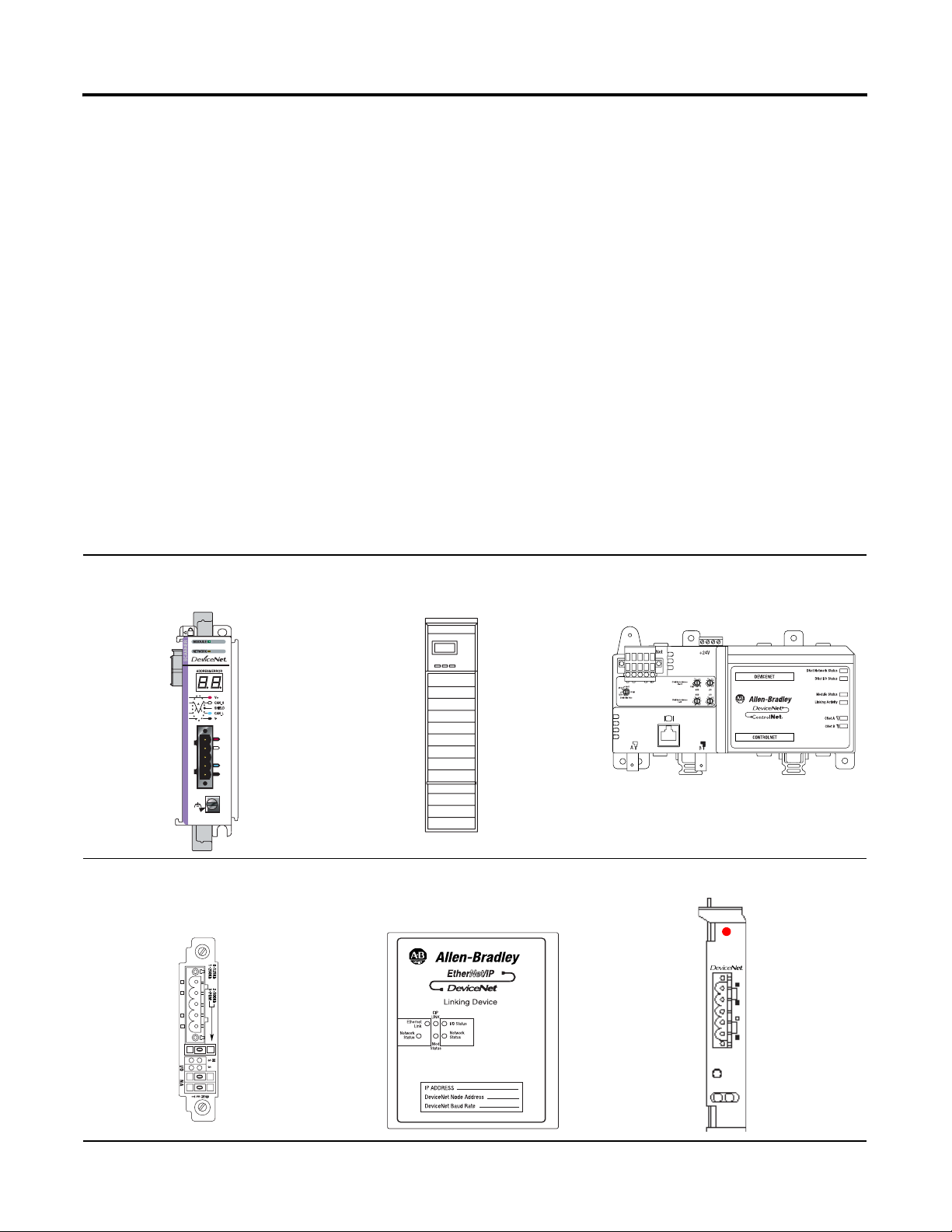
To control the devices on a DeviceNet network, a Logix5000
controller uses one of the following scanners:
CompactLogix™ Scanner 1769-SDN ControlLogix® Scanner 1756-DNB
ControlNet to DeviceNet Linking
Device 1788-CN2DN
DriveLogix™ and FlexLogix™
Communication Card 1788-DNBO
N
31288-M
1 Publication DNET-UM004A-EN-P - March 2004
EtherNet/IP to DeviceNet Linking
Device 1788-EN2DN
SoftLogix™ 5800 Scanner 1784-PCIDS
S
Allen-Bradley
1784-PCIDS
Scanner
I/O
MOD NET
Page 14
1-2 Before You Begin
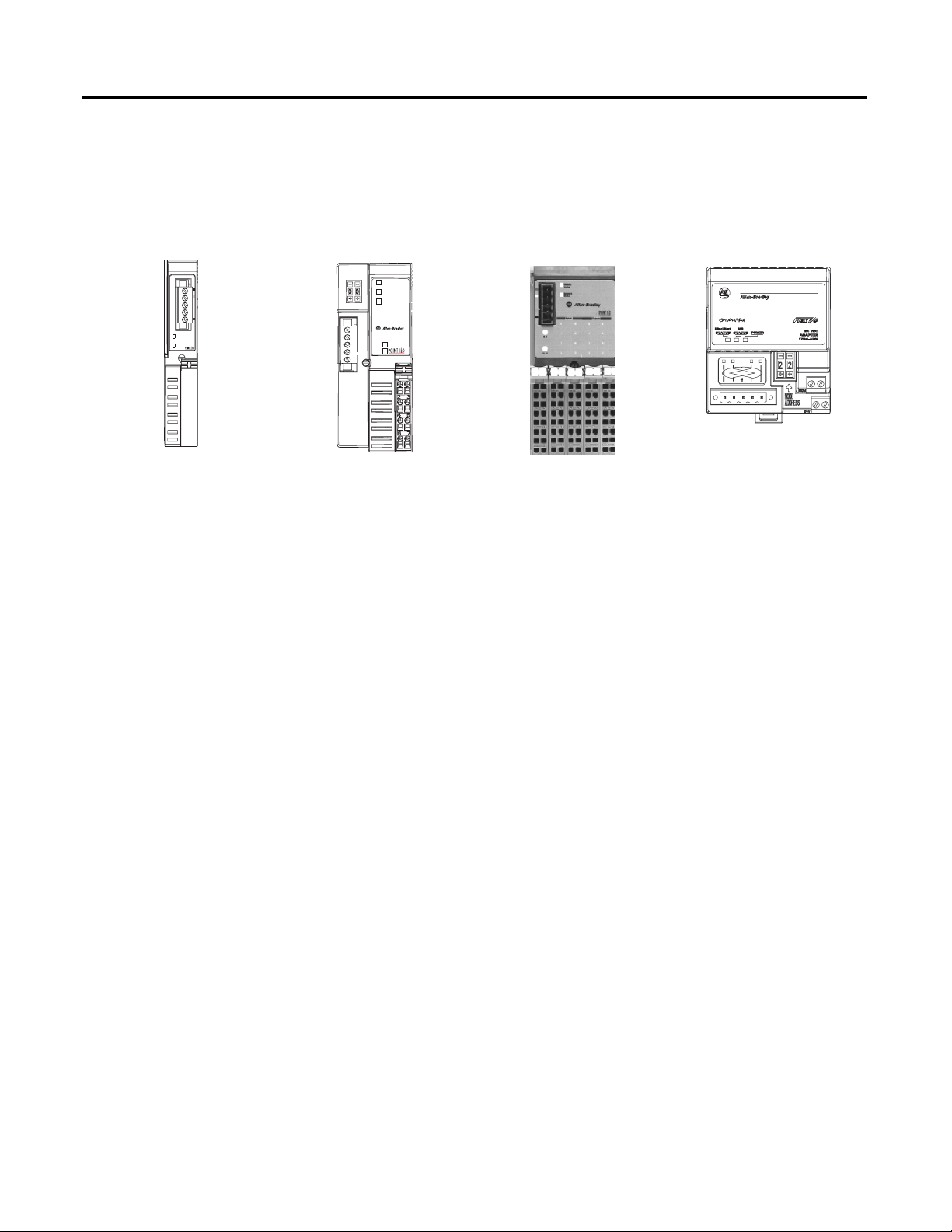
This manual also provides a basic level of information to use the
following devices on your DeviceNet network.
POINT™ I/O Interface
1734-PDN
POINT™ I/O Adapter
1734-ADN and 1734-ADNX
Adapter
Status
DeviceNet
Status
PointBus
Status
1734-ADN
System
Power
DeviceNet
Power
POINT™Block I/O Module
1734D
FLEX™ I/O Adapter
1794-ADN
Publication DNET-UM004A-EN-P - March 2004
Page 15
Before You Begin 1-3
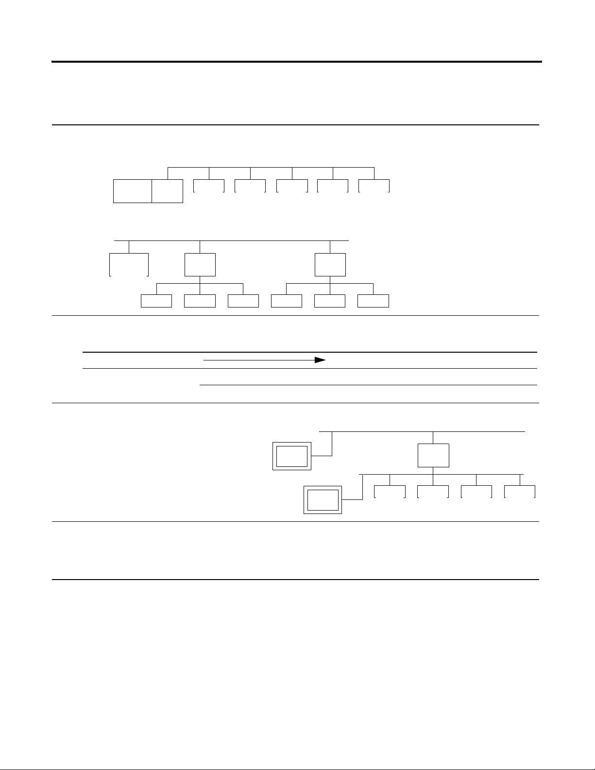
Preliminary Actions
Before you configure and program your DeviceNet network, complete
the following actions:
❑
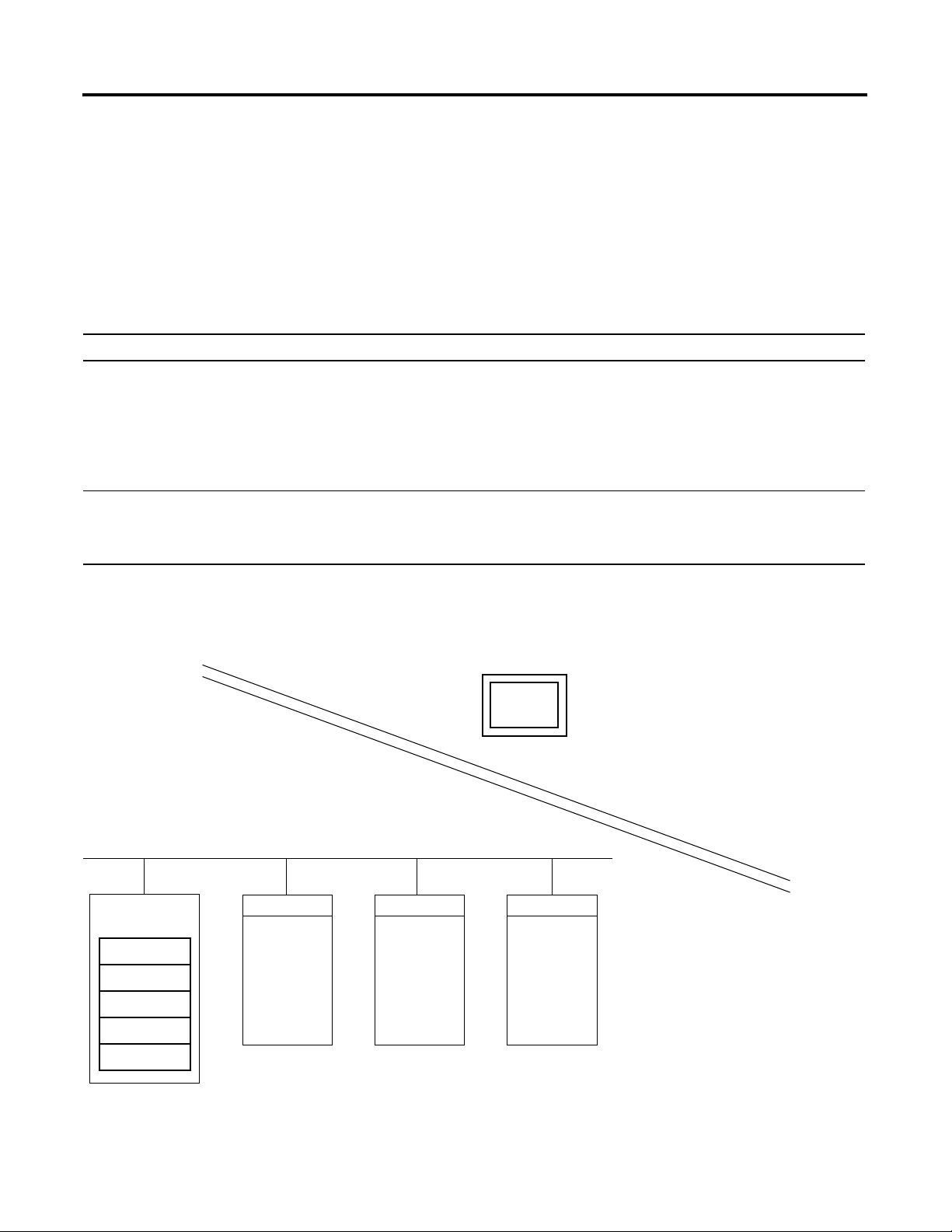
1. Choose whether to use a single network or several distributed networks. (For more information, see page 1-5.)
❑ single network
scannercontroller
device device device device
❑ several smaller distributed networks (subnets)
controller
device
linking
device
device device
❑ 2. Choose a scanner. (For more information, see page 1-5.)
If you are using: And the main network is: Use this scanner:
single network Corresponding scanner for your controller
subnets EtherNet/IP EtherNet/IP to DeviceNet Linking Device 1788-EN2DN
ControlNet™ ControlNet to DeviceNet Linking Device 1788-CN2DN
device
device
linking
device
device device
❑ 3. Choose how to connect your computer to the DeviceNet network. (For more information, see page 1-6.)
Connect to another network and bridge to the
DeviceNet network. Requires a bridge device.
Connect directly to the DeviceNet network. Requires a
device
bridge
device
device device device
DeviceNet interface device.
❑ 4. Choose a baud rate. (For more information, see page 1-9.)
❑ 125K bit/s (default— good starting point)
❑ 250K bit/s
❑ 500K bit/s
Publication DNET-UM004A-EN-P - March 2004
Page 16
1-4 Before You Begin
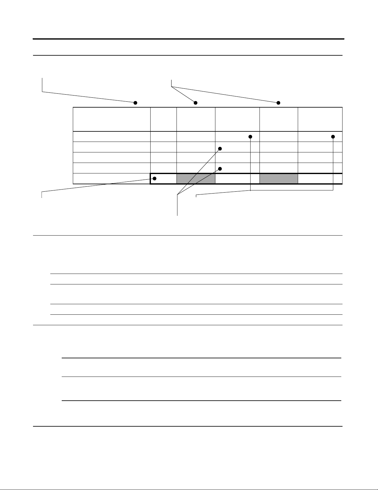
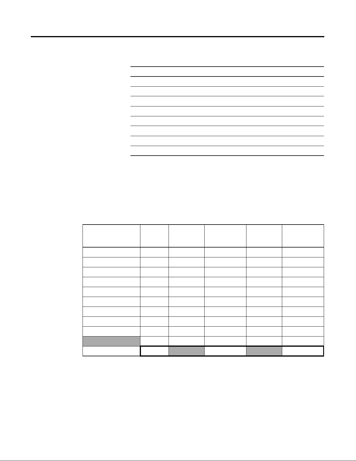
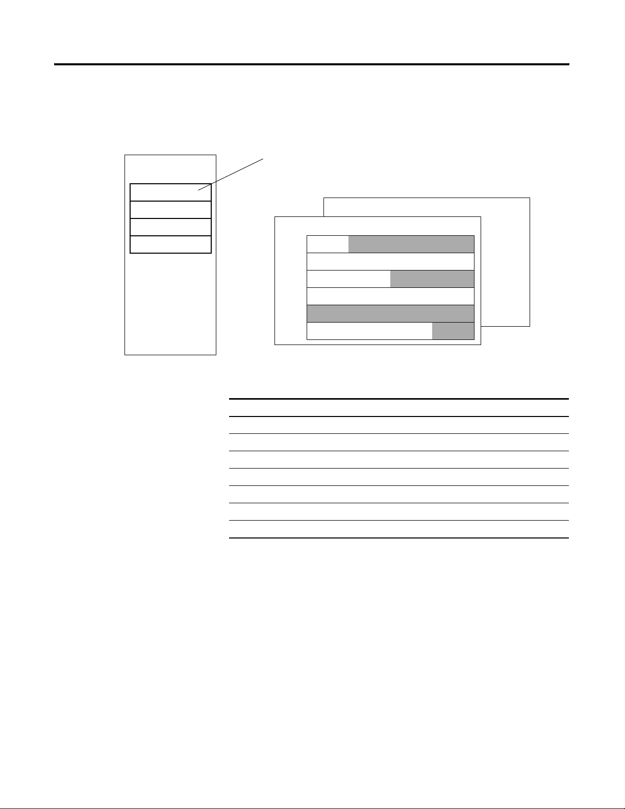
❑ 5. Calculate how much scanner memory you need. (For more information, see page 1-11.)
A. List the devices on your network. B. Record how many bytes each device sends to your control system (input
data) and gets from your control system (output data).
Device Address Input Size of
Device
(bytes)
Input Memory
in Scanner
(DINTs)
Output Size
of Device
(bytes)
Output Memory
in Scanner
(DINTs)
start/stop buttons 1 1 1 1
<empty> 22
I/O adapter w/ modules 9 3 5 2
<empty> 22
E. Total memory that you need in the
scanner.
Total
C. Convert the input and outputs sizes to DINTs, where:
DINTs = (bytes/4) rounded up to an integer.
8 7
D. Add several DINTs between each device in case you want to make
changes later.
❑ 6. Assign an address to each device. The following addresses are recommended but not required. (For more information, see
page 1-13.)
Tip : For flexibility as you develop your system, leave gaps between addresses. Gaps have no effect on system performance.
Give this address: To this device:
0 Scanner
1 to 61 Your devices
Give the lower addresses to devices with 15 bytes or more of input or output data.
62 Computer interface, such as a 1770-KFD or 1784-PCD device
63 Leave open for new or replacement devices.
❑ 7. Make sure you have the required software.
❑ To configure the network:
If: And your scanner is: Configure the network with:
every device on your network (except the scanner)
uses 4 or less bytes of input and output data
some devices use more than 4 bytes of input or
output data
❑ To program the controller, use RSLogix™ 5000 software.
❑ To connect your computer to the network, use RSLinx® software.
Publication DNET-UM004A-EN-P - March 2004
• ControlLogix® 1756-DNB
• FlexLogix™ 1788-DNBO
any RSNetWorx™ for DeviceNet software
RSLogix™ 5000 software (For more
information, see chapter 4.)
(For more information, see chapters 2
and 6.)
Page 17
Before You Begin 1-5
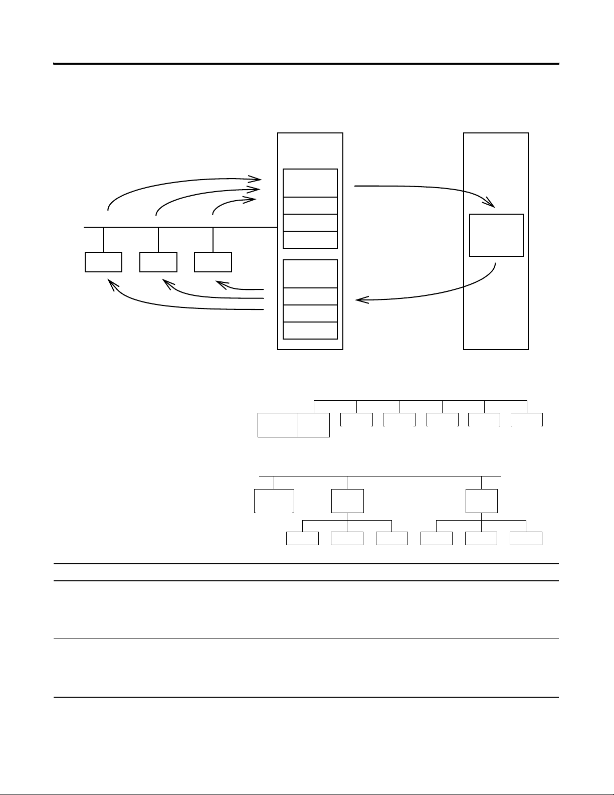
Choose a Scanner
The scanner collects input data from
the devices on the network…
device device device
…and sends the data to the devices.
The DeviceNet scanner connects a controller to the devices on a
DeviceNet network.
scanner
module
Input
Memory
DINT
DINT
DINT
Output
Memory
DINT
DINT
DINT
…and sends the data to
the controller.
The scanner collects output
data from the controller…
controller
controller
data
To organize your devices into a DeviceNet network, either:
Place all your devices on a single network and
connect the controller directly to the network via
scannercontroller
device device device device
device
the scanner.
main network
Break up your devices into several smaller
distributed networks (subnets). Place a scanner
(linking device) on each network. Connect the
scanners to the controller via an EtherNet/IP or
controller
linking
device
subnets
ControlNet network (backbone).
device
device device
device
This option: Has these advantages: And these disadvantages:
single network • lower cost
• 1 network to manage
• scanner is local to the controller
• shorter distances
• more devices on the network = slower
performance on that network
• more power supply requirements
subnets • shorter runs on subnets, more total distance
• fewer devices on the subnet = faster performance
on the subnet
• higher cost
• multiple networks to manage
• scanner is remote from the controller
• simpler power supply requirements
linking
device
device device
Publication DNET-UM004A-EN-P - March 2004
Page 18
1-6 Before You Begin
If you are using: And: Use this scanner:
single network CompactLogix™ controller CompactLogix 1769-SDN
subnets EtherNet/IP main network EtherNet/IP to DeviceNet Linking Device 1788-EN2DN
To choose a scanner, use the following table:
ControlLogix® controller ControlLogix 1756-DNB
DriveLogix™ controller DriveLogix and FlexLogix 1788-DNBO
FlexLogix™ controller
SoftLogix™ 5800 controller SoftLogix5800 1784-PCIDS
ControlNet main network ControlNet to DeviceNet Linking Device 1788-CN2DN
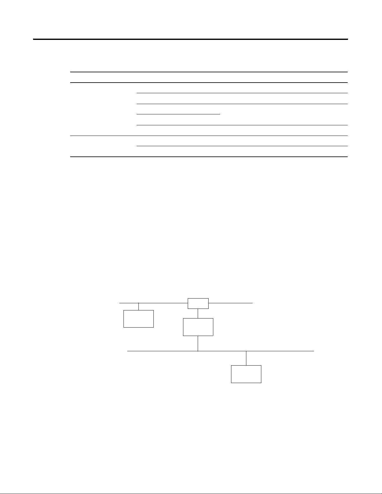
Bridging Across Networks
Device 1
Logix5000™ devices can usually communicate with devices on other
networks with no additional configuration or programming.
• A bridge connects two different networks. The bridge is either:
– single device with communication ports for two different
networks
– separate communication devices in the same chassis
• For example, the bridge device shown below is connected to
both EtherNet/IP and DeviceNet networks. Device 1 on
EtherNet/IP can communicate with Device 2 on DeviceNet
through the bridge.
EtherNet/IP network
switch
bridge
DeviceNet network
Publication DNET-UM004A-EN-P - March 2004
Device 2
Page 19
Before You Begin 1-7
Communication can bridge these networks:.
A device on this network Can access a device on this network:
EtherNet/IP ControlNet: DeviceNet:
EtherNet/IP yes yes yes yes
ControlNet yes yes yes yes
DeviceNet no no yes no
RS-232 yes
(1)
To use RSNetWorx software to configure and schedule a ControlNet network, we recommend that you either:
yes
(1)
yes yes
• connect to an EtherNet/IP network and bridge to the ControlNet network
• use a 1784-PCC interface device to connect directly to the ControlNet network
(2)
Typically, this is a point-to-point connection between a Logix5000 controller and another device, such as a PanelView™
Plus operator terminal.
RS-232
(2)
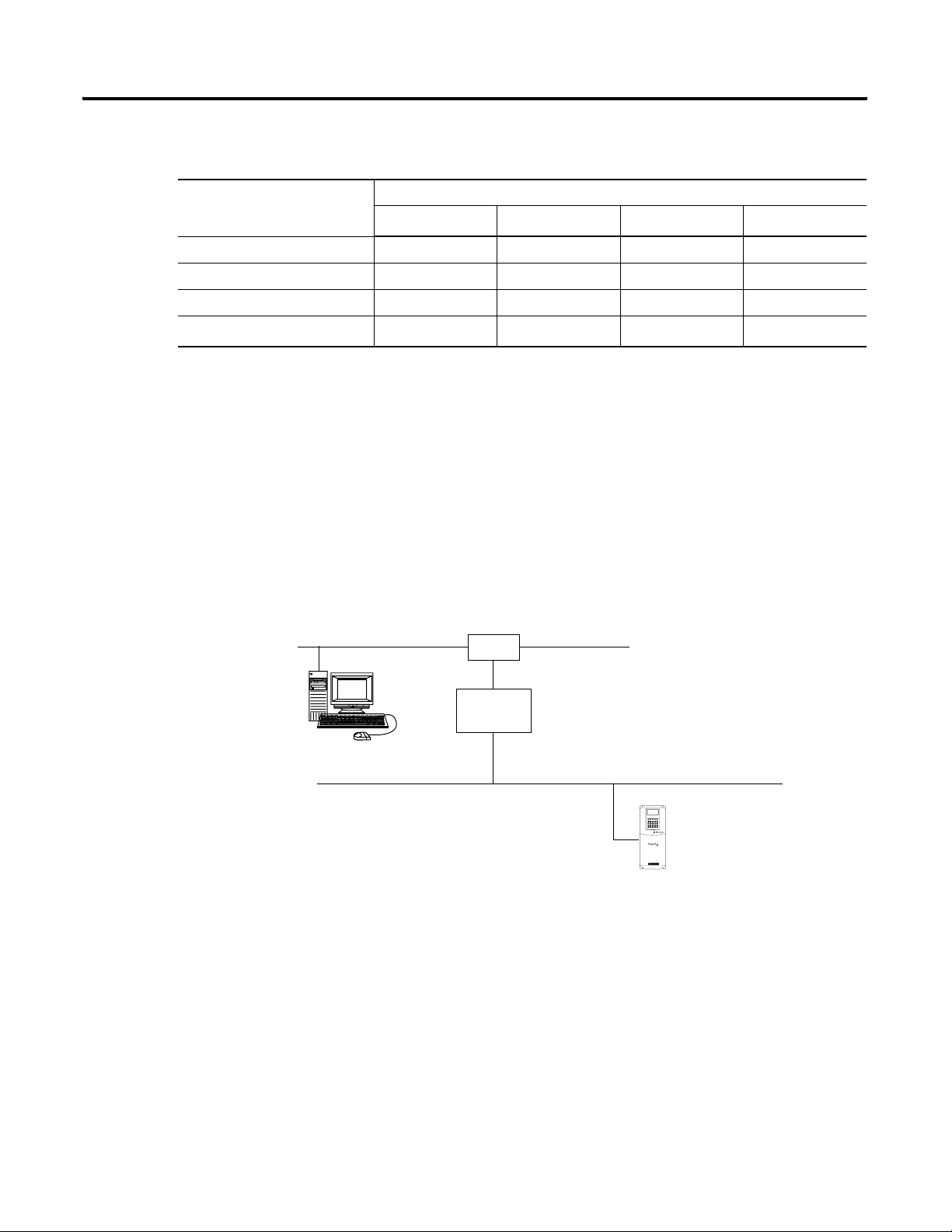
:
workstation
In this example, a workstation configures a drive on a DeviceNet
network. The workstation bridges EtherNet/IP to reach the drive.
EtherNet/IP network
switch
bridge
DeviceNet network
PWR
STS
PORT
MOD
Drive
NET A
NET B
Publication DNET-UM004A-EN-P - March 2004
Page 20
1-8 Before You Begin
EtherNet/IP network
EtherNet/IP bridge in
1756 system
DeviceNet bridge in
same 1756 system
DeviceNet network
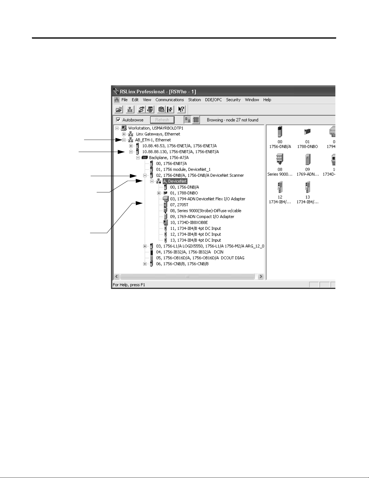
This example RSLinx window shows how the DeviceNet bridge links
to the EtherNet/IP network:
distributed DeviceNet
devices
Publication DNET-UM004A-EN-P - March 2004
Page 21

Before You Begin 1-9
Choose a Baud Rate for the
The default baud rate for a DeviceNet network is 125K bits/s. This is
the easiest baud rate to use and is usually sufficient.
Network
The 2 most common methods to set the baud rate of a device are:
Method: Description:
autobaud feature At power up, the device automatically sets its baud rate to the baud rate of the first device it hears on the network. It
remains set until the device powers up again.
The network requires at least one device with a fixed baud rate so the autobaud devices have something against
which to set. Typically, scanners and network interfaces have a fixed baud rate.
switches or
pushbutton on the
device
software Some devices require a programming device to set its address. For example, you can use your computer and the
Some devices have switches or a pushbutton that set the baud rate.
• The device reads the switch setting at power up.
• Typically, the switch lets you select either:
• autobaud
• fixed baud rate of 125K, 250K, or 500K
• If you change the switch setting, you have to cycle power to the device before the change to takes effect.
There are exceptions. For example, the 1756-DNB module has a pushbutton, which only lets you set the baud rate if
the module is unconnected from the network or network power is off. Once you change the baud rate, the module
automatically resets to the new baud rate.
DeviceNet Node Commissioning tool (software) to set the baud rate of a device. The Node Commissioning tool is
available:
• automatically when you install RSNetWorx for DeviceNet software
• as a separate application on the RSLogix 5000 software CD, revision 13.0 or later
Publication DNET-UM004A-EN-P - March 2004
Page 22

1-10 Before You Begin
If You Want to Use a Higher Baud Rate…
The length of the trunkline and type of cable determines which baud
rates you can use:
Baud rate Maximum distance Cumulative drop line
flat cable thick cable thin cable
125K bit/s 420m (1378 ft) 500m (1640 ft) 100m (328 ft) 156 m (512 ft)
250K bit/s 200m (656 ft) 250m (820 ft) 100m (328 ft) 78m (256 ft)
500K bit/s 75m (246 ft) 100m (328 ft) 100m (328 ft) 39m (128 ft)
If you change the baud rate of your network, make sure that all
devices change to the new baud rate. Mixed baud rates produce
communication errors.
To set the baud rate for the network:
length
1. Connect the network interface to the network and set its baud
rate.
2. Connect the scanner to the network and set its baud rate.
3. For each device that has only fixed baud rates (no autobaud),
set the baud rate and connect it to the network.
4. Connect the remaining devices to the network and enable
autobaud for each of them.
If a device: Then:
has a switch to enable
autobaud
does not have a switch to
enable autobaud
A. Set the switch to autobaud.
B. Connect the device to the network.
A. Connect the device to the network.
B. Use RSNetWorx software to enable
autobaud.
Publication DNET-UM004A-EN-P - March 2004
Page 23
Before You Begin 1-11
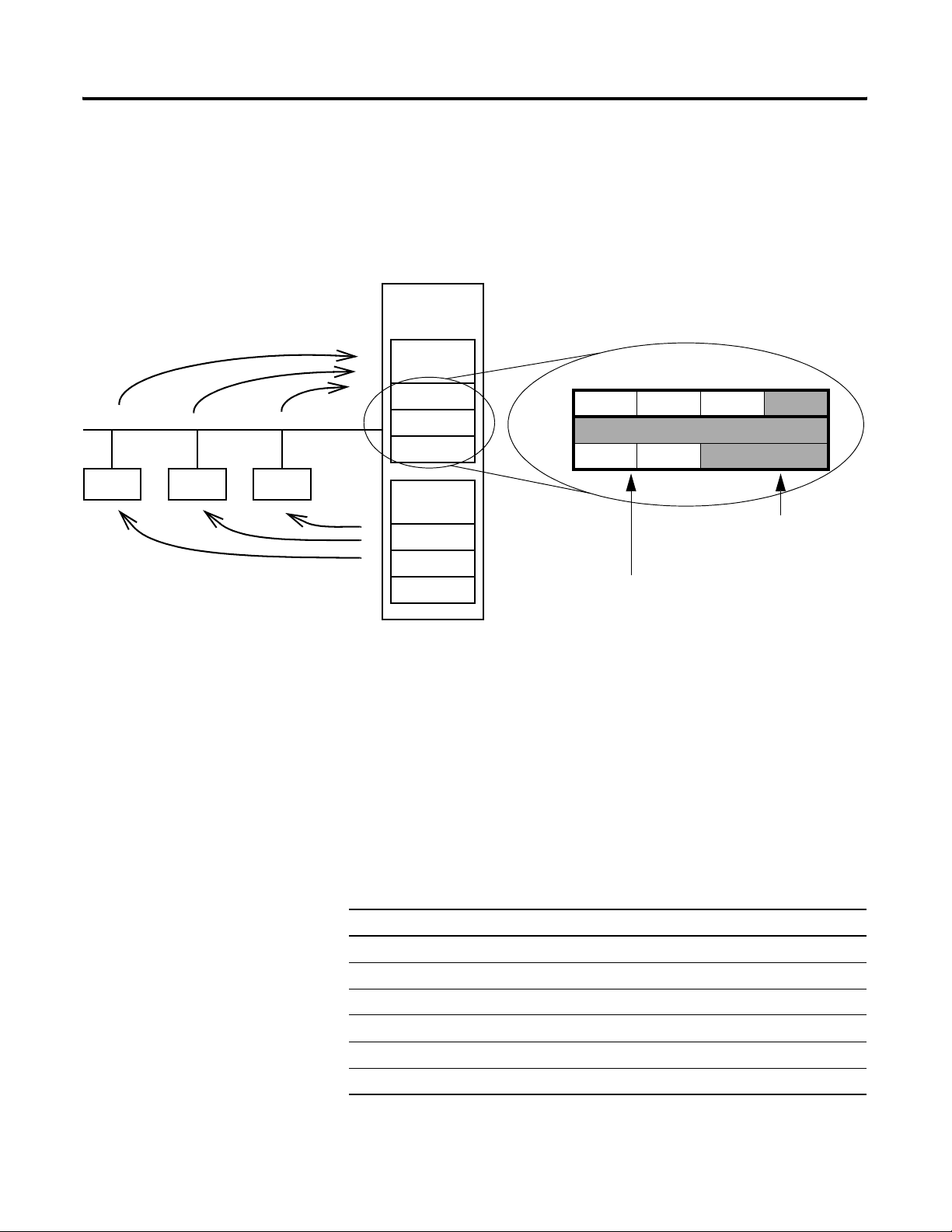
Calculate Scanner Memory Requirements
If a device sends input data, it uses
input memory in the scanner.
device device device
If a device gets output data, it uses
output memory in the scanner.
A Logix5000 scanner has fixed sections of memory for the input and
output data of your network. Each device on your network requires
either some input or output memory of the scanner. Some devices
both send and receive data, so they need both input and output
memory.
The memory of a Logix5000 scanner is organized as an array
scanner
module
Input
Memory
DINT
DINT
DINT
Output
Memory
DINT
DINT
DINT
of DINTs (4-byte elements). A Logix5000 system is easier to
program if you give each device its own DINT or DINTs
within the scanner.
byte 3 byte 2 byte 1 byte 0
DINT
DINT
DINT
Some memory may be left
empty (not used).
Device B
The data fills only the portion
of memory that it needs.
Device A
To make sure your network is within limits, calculate the amount of
input and output memory that the scanner needs. This information
will also be very useful when you configure the scanner.
Check the I/O Limits of the Scanner
Once you tally the input and output data for your network, make sure
it is within the limits of the scanner. If they exceed the limits, use
multiple scanners.
Scanner Maximum input data (DINTs) Maximum output data (DINTs)
1756-DNB 124 123
1769-SDN 90 90
1784-PCIDS 124 123
1788-CN2DN 124 123
1788-EN2DN 124 123
1788-DNBO 124 123
Publication DNET-UM004A-EN-P - March 2004
Page 24
1-12 Before You Begin
If You Are Using a SoftLogix5800 Controller
The 1784-PCIDS scanner organizes its input and output memory in
16-bit increments. When you access the data in the controller, the data
is packed into 32-bit increments (DINTs).
Scanner Input Memory
16 bits
16 bits
16 bits
16 bits
16 bits
16 bits
Controller Input Data
Controller Output DataScanner Output Memory
A Logix5000 system is easier to program if you give each device its
own DINT or DINTs within the controller. To accomplish this with a
PCIDS scanner:
Publication DNET-UM004A-EN-P - March 2004
• Allocate memory in 4-byte increments.
• This may result in some 16-bit words being left unused.
Page 25

Before You Begin 1-13
Assign an Address to Each
To communicate on the DeviceNet network, each device requires its
own address. In general, a device can use any address between 0 to
Device
Give this device: This address: Notes:
scanner 0 If you have multiple scanners, give them the lowest addresses is sequence (0, 1…).
any device on your network
except the scanner
computer interface to the
network
no device 63 Always leave address 63 open. Out of the box, most DeviceNet devices are preset for
1 to 61 • Give the lower addresses to devices with 15 bytes or more of input or output
62 If you connect a computer directly to the DeviceNet network, use address 62 for the
63. However, we recommend that you follow these guidelines:
data.
• Gaps between addresses are OK and have no effect on system performance. If
you are uncertain of the final lay-out of your system, leave gaps between
addresses. This gives you some flexibility as you develop your system.
computer.
• Many computer interface devices use this address as their default.
• Devices such as a 1770-KFD or 1784-PCD connect a computer directly to a
DeviceNet network.
address 63.
• Some devices have no switches or pushbutton to set the address. They require
software such as RSNetWorx for DeviceNet software to change the address. This
means that you must first place it on the network at its preset address of 63
before you can change the address.
• If another device is already using address 63, there will be an address conflict
and you won’t be able to communicate with the newly connected device.
• Leaving address 63 open makes it possible to configure a new device.
• The auto-address recovery feature also requires address 63 to be open.
Publication DNET-UM004A-EN-P - March 2004
Page 26
1-14 Before You Begin
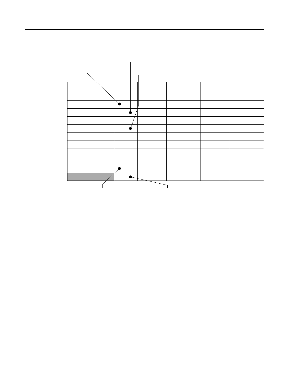
1. Give address 0 to the scanner. 2. Give the lower addresses to devices with 15 bytes or more of input or
Here’s an example:
output data.
3. Gaps in addresses are OK.
Device Address Input Size of
Device
(bytes)
Input Memory
in Scanner
(DINTs)
Output Size
of Device
scanner 0 n/a n/a n/a n/a
PanelView terminal 3 128 32 128 32
<empty> 22
I/O adapter w/ modules 5 9 3 5 2
<empty> 22
drive 74141
<empty> 22
photoeye 9 1 1 0 0
computer interface 62 n/a n/a n/a n/a
63
4. Give address 62 to the computer interface device. 5. Leave address 63 open.
(bytes)
Output Memory
in Scanner
(DINTs)
Publication DNET-UM004A-EN-P - March 2004
Page 27
Configure Your Network Offline
Chapter
2
How to Use This Chapter
To configure your DeviceNet network, you have the following
options:
If: Then configure your network: See:
Any of the following conditions apply:
• The network and devices are not yet installed.
• You do not have access to the network. (I.e., You are
off-site.)
• You prefer to do most of the configuration before you get
on-site with the network.
Both of the following conditions apply:
• The network and devices are already installed.
• You have access to the network. (I.e., You are on-site.)
offline This chapter
online Chapter 6
Offline configuration lets you do most of the DeviceNet configuration
tasks before you connect to the network.
Off-Site
RSNetWorx for DeviceNet software
1. Configure parameters of each device.
2. Configure the scanner to communicate
On-Site
DeviceNet network
Scanner
Scan List
device 1
device 2
device3
…
1 Publication DNET-UM004A-EN-P - March 2004
device 1
parameter 1
parameter 2
parameter 3
…
…
…
device 2
parameter 1
parameter 2
parameter 3
…
…
…
device 3
parameter 1
parameter 2
parameter 3
…
…
…
with the devices on your network.
Page 28
2-2 Configure Your Network Offline
To configure a DeviceNet network while offline:
Step: Page:
❑ Before You Begin 2-2
❑ Create a File for the Network 2-3
❑ Draw Your Network 2-4
❑ Configure Each Device 2-5
❑ Configure the Scanner 2-8
❑ Save the Network File 2-15
❑ Generate an RSNetWorx Report 2-16
❑ Download the Configuration to Network 2-17
Before You Begin
Device Address Input Size of
scanner 0 n/a n/a n/a n/a
PanelView terminal 3 128 32 128 32
<empty> 22
I/O adapter w/ modules 5 9 3 5 2
<empty> 22
drive 74141
<empty> 22
photoeye 9 1 1 0 0
computer interface 62 n/a n/a n/a n/a
Before you configure the network, make sure you have a list of the
devices that you are putting on your network and the address for each
of them.
For example:
63
Total
Device
(bytes)
Input Memory
in Scanner
(DINTs)
43 41
Output Size
of Device
(bytes)
Output Memory
in Scanner
(DINTs)
Publication DNET-UM004A-EN-P - March 2004
Page 29
Configure Your Network Offline 2-3
Create a File for the Network
RSNetWorx software stores information about the configuration of
each device in a file on your computer.
Step: See page:
❑ Create a DeviceNet Configuration File 2-3
❑ Give the File a Descriptive Name 2-3
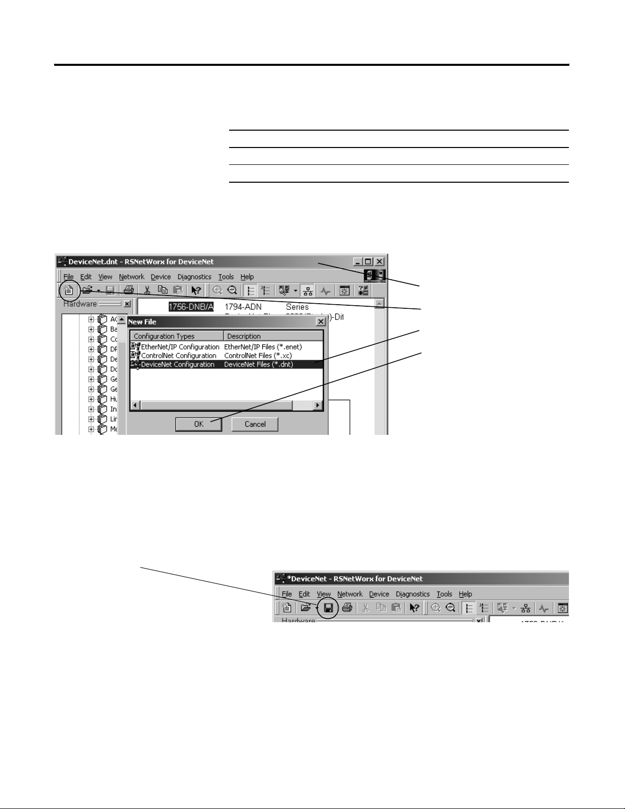
Create a DeviceNet Configuration File
1. Start RSNetWorx software.
2. Create a file.
3. Select DeviceNet Configuration.
4. Choose OK.
Save the file.
Give the File a Descriptive Name
Since the file stores the configuration of the network, give it a name
that identifies this specific DeviceNet network.
As you work in RSNetWorx software, periodically save your changes
to the file for the network.
Publication DNET-UM004A-EN-P - March 2004
Page 30
2-4 Configure Your Network Offline
Draw Your Network
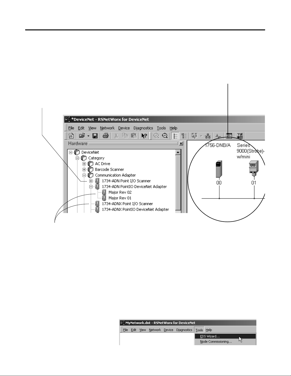
1. Browse the hardware list for the device.
2. If there is a [+] sign next to the device, click the [+] sign.
To configure a DeviceNet network, you use RSNetWorx software to
build a graphical picture of your network. To build a graphical picture
of your network, complete the following steps for each of your
devices:
graphical picture of your network
3. Double-click the major revision of the device.
For a device without a list of major revisions (no + or - sign), double-click the device.
Publication DNET-UM004A-EN-P - March 2004
If Your Device Is Not in the Hardware List…
If the hardware list does not show a device, then RSNetWorx requires
the EDS file for the device:
1. To see if an EDS file is available, go to
www.ab.com/networks/eds/
2. Use the EDS wizard of RSNetWorx software to register the file.
Page 31

Configure Your Network Offline 2-5
Configure Each Device
Typically, a DeviceNet device has a set of parameters that define the
behavior of the device.
To configure a device offline:
Step: See page:
❑ Specify the Address of the Device 2-6
❑ Configure the Parameters of the Device 2-7
Publication DNET-UM004A-EN-P - March 2004
Page 32

2-6 Configure Your Network Offline
Specify the Address of the Device
When you are offline, the address on the diagram identifies a device.
It does not set the device to that address. In chapter 5, you will set the
address of each device.
1. Double-click the device.
2. Type or select the DeviceNet address for the
device.
Publication DNET-UM004A-EN-P - March 2004
Page 33

Configure Your Network Offline 2-7
Configure the Parameters of the Device
1. Click the Parameters tab.
2. Set a parameter to the required value:
• Select a new value.
– or –
• Click, type a new value, and press [Enter].
3. Close the dialog box.
Publication DNET-UM004A-EN-P - March 2004
Page 34
2-8 Configure Your Network Offline
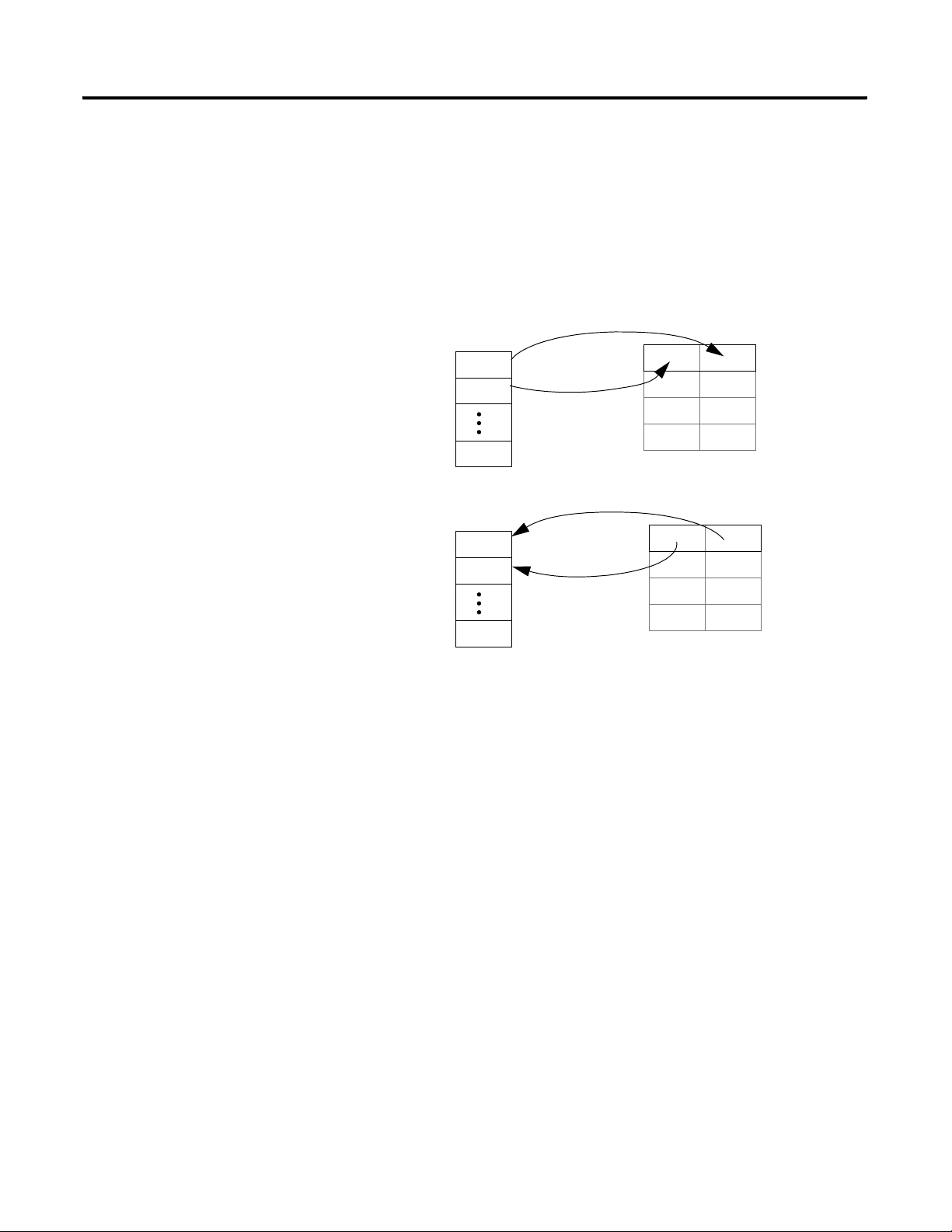
Configure the Scanner
Scanner
Scan List
device at address 1
device at address 2
device at address 3
To configure the scanner to communicate with the devices on your
network, you set up a scan list in the scanner. Then you define
memory locations for the data of each device.
scan list – A list in the scanner that identifies the devices with which the
scanner communicates. For each device in its scan list, the scanner sets aside
input and/or output memory for the data of the device.
Output Memory
DINT Input Memory
0
1
2
3
4
5
device at address 1
device at address 2
device at address 3
To configure the scanner offline:
Step: See page:
❑ Specify the Address of the Scanner 2-9
❑ Define the Properties of the Scanner 2-10
❑ Set the Alignment Option 2-11
❑ Clear or Set the Automap on Add Check Box 2-12
❑ Build the Scan List 2-13
❑ Manually Assign Each Device to a Memory Location 2-14
❑ Close the Configuration of the Scanner 2-15
Publication DNET-UM004A-EN-P - March 2004
Page 35

Specify the Address of the Scanner
1. Double-click the scanner.
2. Type or select the DeviceNet address for the
scanner.
Configure Your Network Offline 2-9
Publication DNET-UM004A-EN-P - March 2004
Page 36

2-10 Configure Your Network Offline
Define the Properties of the Scanner
1. Click the Module tab
2. If this is a CompactLogix scanner (1769-SDN), choose
CompactLogix.
3. If the scanner uses a slot number, type its slot number.
Publication DNET-UM004A-EN-P - March 2004
Page 37

Set the Alignment Option
Configure Your Network Offline 2-11
TIP
The alignment option you choose applies to both the input and
output maps.
1. Click the Input tab.
2. Choose Options.
3. Choose DWord Align.
If You Have a SoftLogix5800 Controller
The SoftLogix5800 scanner 1784-PCIDS organizes its input and output
memory in 16-bit words. For that scanner, choose Word Align.
Publication DNET-UM004A-EN-P - March 2004
Page 38

2-12 Configure Your Network Offline
Clear or Set the Automap on Add Check Box
As an option, RSNetWorx software can automatically assign the
memory location for each device. Depending on how you want to
organize the memory, you may or may not want to use this option.
If you want to: Then:
leave gaps between devices
Memory
device at address 1
device at address 2
device at address 3
place devices in sequential DINTs
Memory
device at address 1
1. Click the Scanlist tab
2. Clear (uncheck) the
Automap on Add check box
After you add your devices to the scan list, manually assign the memory location
for each device.
1. Click the Scanlist tab
device at address 2
device at address 3
Publication DNET-UM004A-EN-P - March 2004
2. Set (check) the Automap on
Add check box.
As you add your devices to the scan list, the software automatically assigns the
memory locations for each device.
Page 39

Build the Scan List
Configure Your Network Offline 2-13
1. You should be at the Scanlist tab
If you get the following warning for a device, see Set the I/O
Parameters of a Device on page 11-6
2. Add devices to the scan list.
To add: Do this:
devices one at a
time
all the devices
at once
Select a device and click the >
button.
Click the >> button.
.
Publication DNET-UM004A-EN-P - March 2004
Page 40

2-14 Configure Your Network Offline
Manually Assign Each Device to a Memory Location
IMPORTANT
1. Click the Input tab.
2. Select the device.
If you used Automap on Add (page 2-12).as you built your scan list,
then skip this section. Each device already has a memory location.
3. Type the element number to which you want to assign the data. This is the
starting point for the data. Larger data sizes wrap to several elements.
For example, to start the data in …Data[3], type 3 in the
Start DWord box.
4. Choose AutoMap.
An entry for the device shows up in the input array.
5. Click the Output tab and repeat steps 2 - 4.
Sometimes, a specific input or output value may end up as the upper
bytes of a DINT in the scanner.
To make your programming easier, use advanced mapping to re-map
the value to its own memory location. For more information, see Give
a Value Its Own Memory Location on page A-1.
Publication DNET-UM004A-EN-P - March 2004
Page 41

Configure Your Network Offline 2-15
Close the Configuration of the Scanner
Close the dialog box.
Save the Network File
Save the file.
After you configure each device on your network, including the
scanner, save the file.
Publication DNET-UM004A-EN-P - March 2004
Page 42

2-16 Configure Your Network Offline
Generate an RSNetWorx Report
1. File ⇒ Generate Report.
2. Entire network
An RSNetWorx report shows the following:
• devices on your network
• memory addresses of those devices in the scanner
• configuration of each device
The report is a very useful reference when you program your system.
The report shows up as an
HTML file.
Publication DNET-UM004A-EN-P - March 2004
Page 43

Configure Your Network Offline 2-17
Download the Configuration to Network
After you configure the network offline, you must download the
configuration to the network. Do this after the network and devices
are installed and you have access to the network.
Step: See page:
❑ Before You Download the Configuration 2-17
❑ Open the Configuration File for the Network 2-17
❑ Go Online to the Network 2-18
❑ Download the Configuration to the Network 2-19
Before You Download the Configuration
Before you download the configuration, your computer must be able
to communicate with each device on your DeviceNet network. Make
sure that you have completed the following steps:
Step: See:
Connect a Computer to the System Chapter 3
1. Start RSNetWorx software.
2. Open the dnt file for the network.
Connect Each Device to the Network Chapter 5
Open the Configuration File for the Network
Publication DNET-UM004A-EN-P - March 2004
Page 44

2-18 Configure Your Network Offline
Go Online to the Network
When you go online to a DeviceNet network, RSNetWorx software
looks at the network (browses) one time and shows you the devices
on the network.
• It does not read (upload) or change (download) the parameters
of any of the devices.
• The picture you see remains static. It does not show any changes
since the last browse.
1. Go online.
2. Browse to the DeviceNet network.
3. Choose OK.
The message is telling you that the
software is not going to read or
change the parameters of the
devices. You do that in the next
step.
Publication DNET-UM004A-EN-P - March 2004
4. Check that you are online.
Page 45

Configure Your Network Offline 2-19
Download the Configuration to the Network
IMPORTANT
1. Network ⇒ Download to Network.
2. Yes, download the entire network.
Make sure the scanner is in idle mode. To put the scanner in idle
mode, either:
• Turn off the …O.CommandRegister.Run bit of the scanner.
- or -
• Place the controller in program/remote program mode.
Publication DNET-UM004A-EN-P - March 2004
Page 46

2-20 Configure Your Network Offline
Notes:
Publication DNET-UM004A-EN-P - March 2004
Page 47

Connect a Computer to the System
Chapter
3
How to Use This Chapter
This chapter shows how to connect a computer to your system so you
can:
• configure the devices on the network
• configure network parameters
• upload, download, monitor, and program projects for Logix5000
controllers
Some networks let you browse (bridge) to other networks in your
system. This lets you connect to one network and access devices or
controllers on other networks.
To access your system, choose a network to which to connect and
configure a driver for the network.
For this information: See page:
Connect a Computer to a Network 3-2
Configure a Driver for a Network 3-3
1 Publication DNET-UM004A-EN-P - March 2004
Page 48

3-2 Connect a Computer to the System
Connect a Computer to a Network
IMPORTANT
To access a network, either:
• connect directly to the network
• connect to a different network and browse (bridge) to the
desired network. This requires no additional programming.
To use RSNetWorx software to configure and schedule a ControlNet
network, either:
• connect to an EtherNet/IP network and bridge to the ControlNet
network
• use a 1784-PCC interface device to connect directly to the
ControlNet network
The following diagram shows your options:
ports, cards, or modules in a Logix5000 controller, chassis, or linking device
Logix5000
controller
EtherNet/IP
port
ControlNet
port
DeviceNet
port
ethernet card
serial port
EtherNet/IP network
Laptop Desktop
1784-PCC 1784-PCIC
1770-KFC15 1784-PCICS
1784-KTCX15
1770-KFC15
point-to-point
RS-232
connection
ControlNet network
Laptop Desktop
1784-PCD 1784-PCID
Only lets you access
devices on the
DeviceNet network
DeviceNet network
If you connect directly to a DeviceNet
network, you can access only the devices
on that network.
Publication DNET-UM004A-EN-P - March 2004
1770-KFD 1784-PCIDS
1770-KFD
Page 49

Connect a Computer to the System 3-3
Once you choose a network to which to connect:
• Install the communication card, if required.
• Determine any network parameters for the computer, such as a
network address.
• Connect the computer to the network with the correct cable.
Configure a Driver for a Network
1. Start RSLinx software.
2. Click the Configure Driver button.
3. Add the driver:
For this network: Select this driver:
RS-232 RS-232 DF1 Devices
To communicate over a specific network, configure a driver for the
network.
Add the Driver
ControlNet™ driver that matches your card.
EtherNet/IP Ethernet devices
DeviceNet™ DeviceNet Drivers…
4. Configure the driver.
descriptive name for the network (driver)
configuration (see pages 3-4 to 3-5 for help with specific drivers)
Publication DNET-UM004A-EN-P - March 2004
Page 50

3-4 Connect a Computer to the System
RS-232 DF1 Devices
Important: Make sure no other driver is configured for the
COM port to which you connect the serial cable.
1. Choose the following:
COM port that you are using.
Logix 5550/CompactLogix.
Auto-Configure
5. Wait for the auto-configuration to finish.
Ethernet Devices
1784-PCC
Enter the IP address of the controller or communication
module.
Use the address that the software picks.
Or assign a specific address:
A. Clear this check box.
B. Enter the address that you to use.
Publication DNET-UM004A-EN-P - March 2004
Page 51

1784-PCD
1. Use the default address of 62, if it is
unused.
2. Select the baud rate for the network.
3. OK.
Connect a Computer to the System 3-5
1770-KFD
Important: Make sure no other driver is configured for the COM
port to which you connect the serial cable.
1. Select the COM port to which you connected the 1770-KFD
device.
2. Use the default address of 62, if it is unused.
3. Select the baud rate for the network.
4. OK.
Publication DNET-UM004A-EN-P - March 2004
Page 52

3-6 Connect a Computer to the System
3. Open the RSWho window.
Make Sure the Driver Works
1. Check that the driver is running.
2. Close the dialog box.
4. Double-click the driver to see the network.
Publication DNET-UM004A-EN-P - March 2004
Page 53

Chapter
Automatically Configure a DeviceNet
Network
4
How To Use This Chapter
Before you use this chapter:
Connect your computer to the
system. See chapter 4.
Determine If You Can Use AutoScan
This chapter provides a quick method for configuring a DeviceNet
network. It uses the AutoScan feature to establish communication
between the controller and your devices with minimal steps.
To use the AutoScan feature to configure your network:
Step: Page:
❑ Determine If You Can Use AutoScan 4-1
❑ Review How AutoScan Effects Your Network 4-2
❑ Install the Node Commissioning Tool 4-2
❑ Connect Each Device to the Network 4-3
❑ Add the Scanner to the RSLogix 5000 Project 4-6
❑ Turn On AutoScan 4-7
❑ Access Device Data 4-9
❑ Put the Scanner in Run Mode 4-11
❑ Additional Information About AutoScan 4-12
To use this chapter, make sure your network meets the following
requirements:
Each device on your DeviceNet network (except the scanner):
• sends ≤ 4 bytes of input data
• gets ≤ 4 bytes of output data
You have one of the following DeviceNet scanners:
• ControlLogix 1756-DNB
• FlexLogix 1788-DNBO
Your scanner has the following firmware revision:
This scanner: Requires this firmware:
ControlLogix 1756-DNB revision 5.0 or greater
FlexLogix 1788-DNBO revision 3.0 or greater
You have RSLogix 5000 software revision 13.0 or greater.
If your network does not meet the requirements listed above, then use
chapters 5 to 7 to configure your network and control your devices.
1 Publication DNET-UM004A-EN-P - March 2004
Page 54

4-2 Automatically Configure a DeviceNet Network
How AutoScan Effects Your
As you use AutoScan, keep the following in mind:
Network
Consideration: Description:
1. AutoScan clears the current
configuration.
2. AutoScan allocates a fixed memory
size for each device.
The actual data for the device fills the portion
that it needs and the rest remains unused.
3. New devices are automatically
available.
4. The Automatic Device Recovery
(ADR) option is not available.
With AutoScan, the scanner automatically sets up communication with the devices on your
DeviceNet network. When you turn on the AutoScan option, the scanner removes any
previous configuration that was done to the scanner.
At its default setting, AutoScan allocates 1 DINT of input memory and 1 DINT of output
memory for each device on the DeviceNet network.
While the scanner is in idle mode, AutoScan continues to establish communication with
devices that you connect to the network (as long as the device uses ≤ 4 bytes of input data
and ≤ 4 bytes of output data).
To use the Automatic Device Recovery (ADR) option of a DeviceNet scanner, you have to
use RSNetWorx software to edit the configuration of the scanner. This turns off AutoScan.
DINT Input Memory
0
1
2
device at address 0
device at address 1
device at address 2
Install the Node Commissioning Tool
Use this tool to set the DeviceNet address of a device that has no
switch, pushbutton, or other mechanism for its address.
If all your devices have a switch or pushbutton for their address, then
skip this step. You do not need the Node Commissioning tool.
To install the Node Commissioning tool:
1. Get your RSLogix 5000 software CD.
2. On the CD, find the following folder:
language\Tools\Node Commissioning Tool
where:
language is the language of your software. For example, for
software in English, open the ENU folder.
3. Follow the instructions in the readmefirst file.
Publication DNET-UM004A-EN-P - March 2004
Page 55

Automatically Configure a DeviceNet Network 4-3
Connect Each Device to the
As you connect your devices to the DeviceNet network, follow these
guidelines:
Network
Step: Details:
❑ 1. Assign an address to each
device.
❑ 2. Connect the scanner and any
network interface to the
network.
❑ 3. Connect the rest of your devices
to the network one at a time.
The following addresses are recommended but not required:
Give this address: To this device:
0 scanner
1 to 61 your devices
62 computer interface to the network, such as a 1770-KFD or
63 Leave open. Out of the box, a DeviceNet device is preset for
By first connecting the scanner and/or network interface device to the network, you reduce
the number of baud rate errors as you connect the rest of your devices:
1784-PCD device
address 63. Leaving address 63 open lets you get a new device on
the network without conflicting with another device.
• Scanners and network interface devices use a fixed baud rate.
• Sensors and similar DeviceNet devices use autobaud to set their baud rate. They
wait for another device to communicate. Then they set their baud rate to the same
baud rate as the other device.
• By first placing a scanner or network interface on the network, the other device
have a baud rate against which to set their baud rate.
• Initially, leave the baud rate of the scanner and network interface at the default
setting of 125K bits/s. If you want to change the baud rate, wait until after you
establish communication with all your devices at the default setting (125K).
• To set the DeviceNet address of the scanner, see Set the Address of a Scanner on
page 4-4.
• Out of the box, a DeviceNet device is preset for address 63. To avoid address
conflicts, connect and set the devices one at a time. Otherwise the address conflicts
may prevent communication with them.
• If a device has a switch to set its baud rate, set the switch to autobaud, if available.
Otherwise, set the device to the baud rate of the network.
• After you change the address or baud rate of a device via a switch, cycle power to
the device.
• If a device has no switch or pushbutton for its address or baud rate, see Set the
Address and Baud Rate of a Device Via Software on page 4-5.
• After you set the address of a device, check its network status indicator. Typically, a
solid red or flashing red indicator means an address conflict or problem with the
baud rate.
Publication DNET-UM004A-EN-P - March 2004
Page 56

4-4 Automatically Configure a DeviceNet Network
DeviceNet
TM
MOD/NET I/O OK
1. Connect the device to the network. (If disconnected or the network power is off, the
2. Turn on the power to the device.
3. Press and hold the manual configuration pushbutton until the device displays the desired
4. After the device resets, check the 4-character display on the front of the module:
Set the Address of a Scanner
ControlLogix Scanner 1756-DNB
pushbutton changes the baud rate.)
address.
When you release the button, the device resets to the new address.
If: Then the:
A#address address is OK
Duplicate Node Address address conflicts with another device
DriveLogix and FlexLogix Scanner 1788-DNBO
N
31288-M
1. To change the address, press the button above or below a number.
2. Connect the device to the network.
3. Turn on power to the device.
4. Check the NS (network status) light.
If: Then the:
green (flashing or solid) address is OK
solid red address and/or baud rate conflict with another device
Publication DNET-UM004A-EN-P - March 2004
Page 57

1. Start the Node Commissioning tool.
3. Check this box.
4. Browse to the DeviceNet network.
Automatically Configure a DeviceNet Network 4-5
Set the Address and Baud Rate of a Device Via Software
2. Click Browse.
5. Type the current address for the
device. Out of the box, a device
uses address 63.
7. Type the new address for the device.
8. Select the baud rate for the device.
9. Apply the change.
10. Look for confirmation here.
6. Click OK.
Publication DNET-UM004A-EN-P - March 2004
Page 58

4-6 Automatically Configure a DeviceNet Network
Add the Scanner to the RSLogix 5000 Project
To access the data of your network, add the scanner to the I/O
configuration of the controller. To add a scanner:
Step: See page:
❑ Add the Scanner to the I/O Configuration Folder 4-6
❑ Define the Properties of the Scanner 4-7
Add the Scanner to the I/O Configuration Folder
1. Right-click and choose New Module.
2. Choose the type of scanner.
3. Select the major revision of the scanner.
Publication DNET-UM004A-EN-P - March 2004
Page 59

Automatically Configure a DeviceNet Network 4-7
Define the Properties of the Scanner
1. Type a name for the scanner.
2. Type or select the slot number of
the scanner.
3. Choose Finish.
Turn On AutoScan
1. Save your changes. 2. Download the project to the controller.
To turn on AutoScan:
Step: See page:
❑ Download the RSLogix 5000 Project and Go Online 4-7
❑ Turn On AutoScan 4-8
Download the RSLogix 5000 Project and Go Online
Publication DNET-UM004A-EN-P - March 2004
Page 60

4-8 Automatically Configure a DeviceNet Network
Turn On AutoScan
IMPORTANT
3. Select (check) this check box.
4. Choose OK.
In the following steps, you clear any existing configuration from the
scanner and reconfigure its to communicate with the devices on your
network.
• In the controller, this may change the tag addresses of the devices.
• If you have already programmed your logic, make sure that it still
addresses the correct data.
1. Double-click the scanner.
2. Click the Scan List tab.
Publication DNET-UM004A-EN-P - March 2004
A blue dot indicates a device that the scanner now
controls.
Page 61

Automatically Configure a DeviceNet Network 4-9
Access Device Data
input data from the scanner
output data for the scanner
status data from the scanner
When you add the scanner to the I/O configuration of the controller,
RSLogix 5000 software automatically creates a set of tags for the input,
output, and status data of the network:
The tags for your DeviceNet data follow this format:
location :type .Data [dnet_address] .bit
= Optional
Where: Is:
location location of the scanner in the system
If you have this scanner: In a: Then location is:
ControlLogix 1756-DNB local chassis Local:slot_number_of_scanner
remote chassis adapter:slot_number_of_scanner
where:
adapter is the name of the EtherNet/IP or ControlNet
module in the remote chassis.
FlexLogix 1788-DNBO name of the scanner in the I/O configuration of the controller
type type of data:
Where: Is:
input from a device I
output to a device O
dnet_address address of the device on the DeviceNet network (based on 4 bytes per node)
bit specific bit within the data of the device
Publication DNET-UM004A-EN-P - March 2004
Page 62

4-10 Automatically Configure a DeviceNet Network
While you can use the input and output tags of the scanner directly in
your logic, it is a lot easier to use alias tags.
As an option, create tags that describe each device without pointing them to
the actual addresses of the devices. Later, convert the tags to aliases for the
data of the devices.
alias tag – a tag that represents another tag
• Both tags share the same data.
• When the data changes, both tags change.
• An alias tag provides a descriptive name for
data, such as DeviceNet input or output data.
• If the location of the data changes, simply point
the alias tag lets to the new location without
editing your logic.
1. Enter your logic.
4. Select the Alias button.
5. Select the tag that this alias tag represents.
6. Select the scope for the alias tag.
2. Type a descriptive tag name for the DeviceNet data.
3. Right-click the tag name and choose
New…
7. Choose OK.
Look in the
controller-scoped tags.
Publication DNET-UM004A-EN-P - March 2004
Select the address of the data.
To select a bit, click the ▼.
Page 63

Automatically Configure a DeviceNet Network 4-11
Put the Scanner in Run Mode
To put the scanner in run
mode, turn on this bit.
To run the DeviceNet network:
1. Place the controller in run/remote run mode.
2. Set the following bit of the output structure for the scanner:
If you want to: The set this bit: To:
run the network …O.CommandRegister.Run 1
not run the network (idle mode) …O.CommandRegister.Run 0
fault the network …O.CommandRegister.Fault 1
not fault the network …O.CommandRegister.Fault 0
disable the network …O.CommandRegister.DisableNetwork 1
enable the network …O.CommandRegister.DisableNetwork 0
halt the scanner (ceases all operation) …O.CommandRegister.HaltScanner 1
unhalt the scanner …O.CommandRegister.HaltScanner 0
reset the scanner …O.CommandRegister.Reset 1
resume operation after a reset …O.CommandRegister.Reset 0
3. Check the scanner for run mode:
If you have this scanner: Then this indicator: Displays:
ControlLogix 1756-DNB 4-character display RUN
FlexLogix 1788-DNBO I/O solid green
Publication DNET-UM004A-EN-P - March 2004
Page 64

4-12 Automatically Configure a DeviceNet Network
Additional Information About AutoScan
Type of Connection that the Scanner Sets Up
The type of update (connection) that the scanner sets up with each
device depends on the device. The scanner chooses the first
connection type that the device supports in this order:
1. change-of-state (COS)
2. polled
3. strobed
4. cyclic at 1000 ms
The scanner tries to set up a change-of-state connection. If the device
doesn’t support change-of-state, then the scanner tries to set up a
polled connection, etc. The type of connection that the scanner sets
up may not be the default for the device.
Allocating More Memory for Each Device
The AutoScan feature is easiest to use if you leave it set to 1 DINT
(4 bytes) of input memory and output memory for each address.
number of bytes of input memory and output
memory to allocate in for each address
As an option, you can allocate more memory for each device.
Publication DNET-UM004A-EN-P - March 2004
Page 65

Consideration: Description:
Automatically Configure a DeviceNet Network 4-13
1. The bytes/node value defines how
much memory for each address.
For example, if you specify 2 DINTs (8 bytes)
per address, the scanner sets aside 2 DINTs
The actual data for the device fills the portion
that it needs and the rest remains unused.
2. The scanner sets-up communication
with any device that fits within the
allocated memory size.
3. The scanner skips devices that are
too large.
AutoScan lets you specify how much input and output memory to give to each address on
your network.
DINT Input Memory
for each address.
0
1
2
device at address 0
device at address 1
3
4
device at address 2
5
The scanner automatically sets up communication with those devices that fit within the
memory allocated for each address.
• For example, if you allocate 2 DINTs (8 bytes) per address, the scanner sets up
communication with any device that sends or receives 1 - 8 bytes of data.
• The scanner adds as many device as it can until it runs out of memory.
• If you give too much memory to each address, you may not have enough memory for
all your devices.
If a device needs more memory than is allocated, the scanner skips it and does not set up
communication with it.
For example, if you specify 2 DINTs (8 bytes) per address but a device sends 9 bytes, the
scanner does not add the device to the scan list.
4. Manually editing the scan list turns
off AutoScan.
If you use RSNetWorx software to edit the configuration of the scanner, the scanner turns
off AutoScan. Do not turn it back on or you will clear the configuration that you just
entered.
For example, if you use RSNetWorx software to manually add a device to the scan list, the
scanner turns off AutoScan. If turn on AutoScan again, the scanner clears it current
configuration and starts over.
Publication DNET-UM004A-EN-P - March 2004
Page 66

4-14 Automatically Configure a DeviceNet Network
Notes:
Publication DNET-UM004A-EN-P - March 2004
Page 67

Chapter
Connect Each Device to the Network
5
Using This Chapter
Before You Begin
Device Address Input Size of
scanner 0 n/a n/a n/a n/a
PanelView terminal 3 128 32 128 32
This chapter describes how to set the address of a device so it can
communicate on your DeviceNet network.
For this information: See page:
Before You Begin 5-1
Set the Address of a Device 5-2
Set an Address with Software 5-3
Procedures for Specific Devices 5-4
Make Sure Your Devices Are on the Network 5-11
At this point, you should have a list of the devices that you are putting
on your network and an address for each of them.
For example:
Device
(bytes)
Input Memory
in Scanner
(DINTs)
Output Size
of Device
(bytes)
Output Memory
in Scanner
(DINTs)
<empty> 22
I/O adapter w/ modules 5 9 3 5 2
<empty> 22
drive 74141
<empty> 22
photoeye 9 1 1 0 0
computer interface 62 n/a n/a n/a n/a
63
Total
1 Publication DNET-UM004A-EN-P - March 2004
43 41
Page 68

5-2 Connect Each Device to the Network
Set the Address of a Device
A DeviceNet device uses at least one of the following methods to set
its address on the network:
Method: Description:
switches If a device has switches or another hardware mechanism to set
its network address, use that mechanism. Keep in mind that a
device typically reads the switches on power up. If you change
the address, you usually have to cycle power to the device.
Some switches also let you set the address of the device via
software such as RSNetWorx.
pushbutton Some devices have a pushbutton that lets you cycle through
different addresses.
• Usually, the pushbutton is optional.
• You can typically also set the address of the device via
software such as RSNetWorx.
software If a device has no switches or other mechanism to set its address,
use RSNetWorx for DeviceNet software. Because a device is
preset to address 63, connect and set the devices one at a time.
Otherwise the address conflicts (all of them at 63) may prevent
communication with them.
Publication DNET-UM004A-EN-P - March 2004
Page 69

Connect Each Device to the Network 5-3
Set an Address with
To use RSNetWorx software to set the address of a device:
Software
1. Choose Start ⇒ Programs ⇒ Rockwell Software ⇒ RSNetWorx ⇒ DeviceNet Node Commissioning Tool.
2. Click Browse.
3. Check this box.
4. Browse to the DeviceNet network.
5. Type the current address for the
device. Out of the box, a device
uses address 63.
7. Type the new address for the device.
8. Apply the change.
9. Look for confirmation here.
6. Click OK.
Publication DNET-UM004A-EN-P - March 2004
Page 70

5-4 Connect Each Device to the Network
Procedures for Specific Devices
DeviceNet
TM
MOD/NET I/O OK
The following sections show how to set the address of specific
devices.
For this device: See page:
ControlLogix Scanner 1756-DNB 5-4
CompactLogix Scanner 1769-SDN 5-4
ControlNet to DeviceNet Linking Device 1788-CN2DN 5-5
DriveLogix and FlexLogix Scanner 1788-DNBO 5-5
EtherNet/IP to DeviceNet Linking Device 1788-EN2DN 5-6
SoftLogix5800 Scanner 1784-PCIDS 5-10
ControlLogix Scanner 1756-DNB
1. Connect the device to the network. (If disconnected or the network power is off, the
pushbutton changes the baud rate.)
2. Turn on the power to the device.
3. Press and hold the manual configuration pushbutton until the device displays the desired
address.
When you release the button, the device resets to the new address.
4. After the device resets, check the 4-character display on the front of the module:
If: Then the:
A#address address is OK
Duplicate Node Address address conflicts with another device
CompactLogix Scanner 1769-SDN
The 1769-SDN device has no hardware mechanism to set its address.
1. Connect the device to the network.
2. Turn on the power to the device.
3. Use RSNetWorx software to set the address of the device. See Set an Address with
Software on page 5-3.
4. After the device resets, check the 2-character display on the front of the device. It shows
the status code and address of the device (status code first, then address).
Publication DNET-UM004A-EN-P - March 2004
Page 71

Connect Each Device to the Network 5-5
ControlNet to DeviceNet Linking Device 1788-CN2DN
1. Set the DeviceNet address.
(Switches shown set to node 26)
2
Do not use the PGM area.
0
PGM
4
6
MSD LSD
2. Set the ControlNet address.
(Switches shown set to node 14)
2
4
0
6
8
MSD LSD
3. Connect the device to the DeviceNet and ControlNet networks.
4. Turn on power to the device.
5. Check the DeviceNet network status light.
If: Then the:
green (flashing or solid) address is OK
solid red address and/or baud rate conflict with another device
2
4
0
6
8
2
4
0
6
8
DriveLogix and FlexLogix Scanner 1788-DNBO
N
31288-M
1. To change the address, press the button above or below a number.
2. Connect the device to the network.
3. Turn on power to the device.
4. Check the NS (network status) light.
If: Then the:
green (flashing or solid) address is OK
solid red address and/or baud rate conflict with another device
Publication DNET-UM004A-EN-P - March 2004
Page 72

5-6 Connect Each Device to the Network
EtherNet/IP to DeviceNet Linking Device 1788-EN2DN
Set the DeviceNet Address
The 1788-EN2DN device has no hardware mechanism to set its DeviceNet address.
1. Connect the device to the network.
2. Turn on the power to the device.
3. Use RSNetWorx software to set the address of the device. See Set an Address with
Software on page 5-3.
4. After the device resets, check the DeviceNet network status indicator:
If: Then the:
green (flashing or solid) address is OK
solid red address and/or baud rate conflict with another device
Go Online to Your DeviceNet Network
1. Start RSNetWorx software.
2. Open a new DeviceNet configuration file.
Disable AutoBaud
By default, AutoBaud is enabled for the linking device. If you use the
linking device as the scanner for the DeviceNet network, disable
AutoBaud for the linking device. The network requires at least one
device with a fixed baud rate, which typically is the scanner.
3. Go online to your DeviceNet network.
Publication DNET-UM004A-EN-P - March 2004
Page 73

Disable AutoBaud
Connect Each Device to the Network 5-7
1. Right-click the device and choose Class
Instance Editor.
2. Select Set Single Attribute.
3. Type the object address:
Class = 3
Instance = 1
Attribute = 64
4. Select Byte.
5. Type a value of 01.
6. Choose Execute.
7. Check that the execution was completed.
Publication DNET-UM004A-EN-P - March 2004
Page 74

5-8 Connect Each Device to the Network
Set the IP Address with BootP/DHCP
If the DIP switch = 0 (default), BootP/DHCP is enabled for the device.
ON
23456781
23456
8
7
ON
1
31421-M
1. Get the ethernet (MAC) address of the device. The ethernet address is on a sticker located on the side of the device. The ethernet
address in a format similar to: 00-0b-db-14-55-35.
2. Start ⇒ Programs ⇒ Rockwell Software ⇒ BOOTP-DHCP server ⇒ BOOTP-DHCP server.
On power up, the device requests an IP address from a BootP/DHCP
server.
RSLinx software includes a BootP/DHCP server that lets you easily
assign an IP configuration to an EtherNet/IP device such as the linking
device.
3. If this is the first time you’ve used the software, specify the default
settings for your network. This typically includes a subnet mask but
may also include other settings shown on the dialog box.
If you’ve previous used the software and need to change these
settings, access the dialog box from Tools ⇒ Network Settings.
4. Double-click the ethernet address of the device.
5. Enter the IP address or host name for the device.
Publication DNET-UM004A-EN-P - March 2004
6. Check that the relation list shows the device and the status line
indicates that the software sent the address to the device.
Page 75
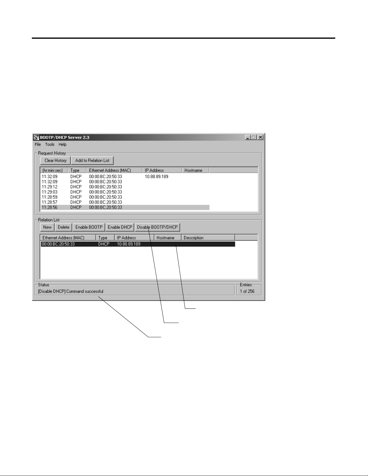
Connect Each Device to the Network 5-9
Turn Off BootP/DHCP
If you leave BootP/DHCP enabled for the device, its IP configuration
lasts only until the next power cycle. After the next power up, the
device sends out a new request for an IP address from a BootP/DHCP
server.
To permanently assign the configuration to the device, disable
BootP/DHCP.
1. Select the device.
2. Disable BootP/DHCP.
3. Check that the command was successful.
Publication DNET-UM004A-EN-P - March 2004
Page 76

5-10 Connect Each Device to the Network
ON
23456781
23456
8
7
ON
1
31421-M
Optional—Set the IP Address with the Configuration DIP Switch
The DIP switch on the end of the linking device lets you set the
device to the following IP configuration.
IP address 192.168.1.n
where:
n is the value of the DIP switch
Subnet mask 255.255.255.0
Gateway address 0.0.0.0 (No gateway set)
IMPORTANT
The numbers on the switch are opposite the address
value bit locations; i.e., bit 0 is set by switch 8.
1. Connect the device to the network.
2. Set the switch to the desired value for n.
3. Turn on or cycle the power to the device.
4. After the device completes its power-up sequence, check the EtherNet/IP Network
Status indicator:
If: Then the:
green (flashing or solid) address is OK
solid red address conflicts with another device
SoftLogix5800 Scanner 1784-PCIDS
The 1784-PCIDS device has no hardware mechanism to set its address.
S
Allen-Bradley
1784-PCIDS
Scanner
I/O
MOD NET
Publication DNET-UM004A-EN-P - March 2004
1. In RSLinx software, configure a driver for the scanner. Refer to Configure a Driver for a
Network on page 3-3.
2. Check the NET light.
If: Then the:
green (flashing or solid) address is OK
solid red address and/or baud rate conflict with another device
Page 77

Connect Each Device to the Network 5-11
Make Sure Your Devices Are on the Network
1. Start RSLinx software.
2. Click the RSWho button.
3. Expand a driver that lets you access
the DeviceNet network.
4. Browse to the DeviceNet network.
5. Make sure you see all the devices
that are connected to the DeviceNet
network.
Once you have assigned an address to each device, make sure that
the devices are communicating on the network.
Publication DNET-UM004A-EN-P - March 2004
Page 78

5-12 Connect Each Device to the Network
Notes:
Publication DNET-UM004A-EN-P - March 2004
Page 79

Configure Your Network Online
Chapter
6
How to Use This Chapter
To configure your DeviceNet network, you have the following
options:
If: Then configure your network: See:
Any of the following conditions apply:
• The network and devices are not yet installed.
• You do not have access to the network. (I.e., You are
off-site.)
• You prefer to do most of the configuration before you get
on-site with the network.
Both of the following conditions apply:
• The network and devices are already installed.
• You have access to the network. (I.e., You are on-site.)
offline Chapter 2
online This chapter
With online configuration, you upload the current configuration of the
network. This reduces the number of configuration steps that you
have to perform. However, it requires access to the DeviceNet
network.
On-Site
RSNetWorx for DeviceNet software
1. Configure parameters of each device.
2. Configure the scanner to communicate
with the devices on your network.
DeviceNet network
Scanner
Scan List
device 1
device 2
device3
…
1 Publication DNET-UM004A-EN-P - March 2004
device 1
parameter 1
parameter 2
parameter 3
…
…
…
device 2
parameter 1
parameter 2
parameter 3
…
…
…
device 3
parameter 1
parameter 2
parameter 3
…
…
…
Page 80

6-2 Configure Your Network Online
To configure a DeviceNet network while online:
Step: Page:
❑ Before You Begin 6-2
❑ Create a File for the Network 6-3
❑ Go Online to the Network 6-5
❑ Configure Each Device 6-6
❑ Configure the Scanner 6-9
❑ Upload and Save the Network File 6-16
❑ Generate an RSNetWorx Report 6-17
Before You Begin
Device Address Input Size of
scanner 0 n/a n/a n/a n/a
PanelView terminal 3 128 32 128 32
<empty> 22
I/O adapter w/ modules 5 9 3 5 2
<empty> 22
drive 74141
<empty> 22
photoeye 9 1 1 0 0
computer interface 62 n/a n/a n/a n/a
Before you configure the network, make sure you have a list of the
devices that you are putting on your network and the address for each
of them.
For example:
63
Device
(bytes)
Input Memory
in Scanner
(DINTs)
Output Size
of Device
(bytes)
Output Memory
in Scanner
(DINTs)
Publication DNET-UM004A-EN-P - March 2004
Total
43 41
To configuration the network online, your computer must also be able
to communicate with each device on your DeviceNet network. Make
sure that you have completed the following steps:
Step: See:
Connect a Computer to the System Chapter 3
Connect Each Device to the Network Chapter 5
Page 81
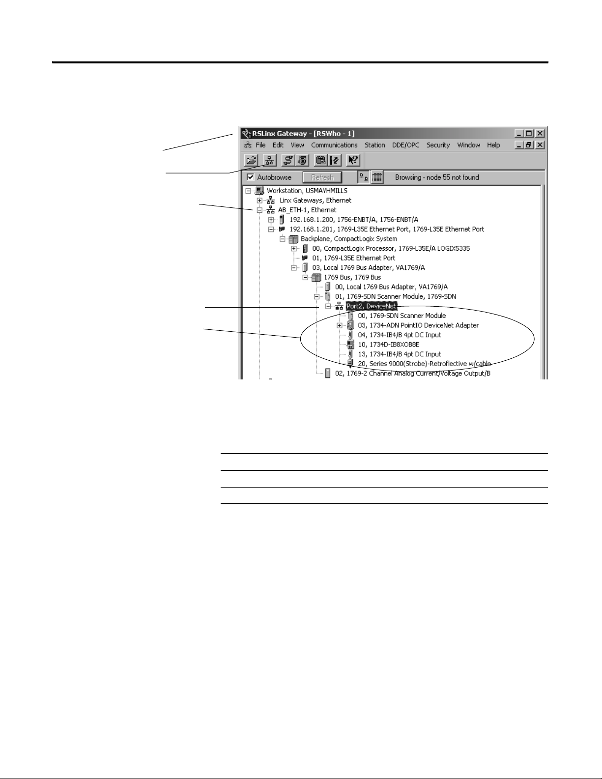
1. Start RSLinx software.
2. Click the RSWho button.
3. Expand a driver that lets you access
the DeviceNet network.
4. Browse to the DeviceNet network.
5. Make sure you see all the devices
that are connected to the DeviceNet
network.
Configure Your Network Online 6-3
To make sure that you can communicate with all your devices, use
RSLinx software to show your DeviceNet network.
Create a File for the Network
RSNetWorx software stores information about the configuration of
each device in a file on your computer.
Step: See page:
❑ Create a DeviceNet Configuration File 6-4
❑ Give the File a Descriptive Name 6-4
Publication DNET-UM004A-EN-P - March 2004
Page 82

6-4 Configure Your Network Online
Create a DeviceNet Configuration File
1. Start RSNetWorx software.
2. Create a file.
3. Select DeviceNet Configuration.
4. Choose OK.
Save the file.
Give the File a Descriptive Name
Since the file stores the configuration of the network, give it a name
that identifies this specific DeviceNet network.
As you work in RSNetWorx software, periodically save your changes
to the file for the network.
Publication DNET-UM004A-EN-P - March 2004
Page 83

Configure Your Network Online 6-5
Go Online to the Network
When you go online to a DeviceNet network, RSNetWorx software
looks at the network (browses) one time and shows you the devices
on the network.
• It does not read (upload) or change (download) the parameters
of any of the devices.
• The picture you see remains static. It does not show any changes
since the last browse.
1. Go online.
2. Browse to the DeviceNet network.
3. Choose OK.
The message is telling you that the
software is not going to read or
change the parameters of the
devices. You do that in the next
step.
4. Check that you are online.
Publication DNET-UM004A-EN-P - March 2004
Page 84

6-6 Configure Your Network Online
Configure Each Device
Typically, a DeviceNet device has a set of parameters that define the
behavior of the device.
Publication DNET-UM004A-EN-P - March 2004
To configure a device online:
Step: See page:
❑ Upload the Configuration of a Device 6-7
❑ Change and Download Parameters 6-8
Page 85

Upload the Configuration of a Device
1. Double-click the device.
Configure Your Network Online 6-7
2. Click the Parameters tab.
3. Upload the configuration
from the device.
Publication DNET-UM004A-EN-P - March 2004
Page 86

6-8 Configure Your Network Online
Change and Download Parameters
1. Change a parameter:
• Select a new value.
– or –
• Click, type a new value, and press [Enter].
2. Apply the changes.
3. Download the changes.
4. Close the dialog box.
Publication DNET-UM004A-EN-P - March 2004
Page 87

Configure Your Network Online 6-9
Configure the Scanner
Scanner
Scan List
device at address 1
device at address 2
device at address 3
To configure the scanner to communicate with the devices on your
network, you set up a scan list in the scanner. Then you define
memory locations for the data of each device.
scan list – A list in the scanner that identifies the devices with which the
scanner communicates. For each device in its scan list, the scanner sets aside
input and/or output memory for the data of the device.
Output Memory
DINT Input Memory
0
1
2
3
4
5
device at address 1
device at address 2
device at address 3
To configure the scanner online:
Step: See page:
❑ Upload the Current Configuration of the Scanner 6-10
❑ Define the Properties of the Scanner 6-11
❑ Set the Alignment Option 6-12
❑ Clear or Set the Automap on Add Check Box 6-13
❑ Build the Scan List 6-14
❑ Manually Assign Each Device to a Memory Location 6-15
❑ Download the Configuration to the Scanner 6-16
Publication DNET-UM004A-EN-P - March 2004
Page 88

6-10 Configure Your Network Online
Upload the Current Configuration of the Scanner
1. Double-click the scanner.
2. Click the Module tab.
3. Upload the configuration
from the scanner.
Publication DNET-UM004A-EN-P - March 2004
Page 89
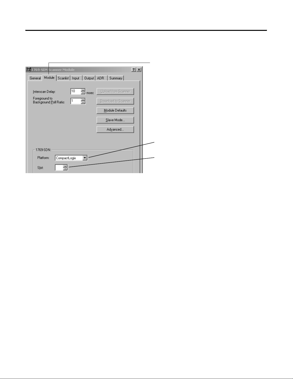
Define the Properties of the Scanner
1. Click the Module tab
2. If this is a CompactLogix scanner (1769-SDN), choose
CompactLogix.
3. If the scanner uses a slot number, type its slot number.
Configure Your Network Online 6-11
Publication DNET-UM004A-EN-P - March 2004
Page 90

6-12 Configure Your Network Online
Set the Alignment Option
TIP
The alignment option you choose applies to both the input and
output maps.
1. Click the Input tab.
2. Choose Options.
3. Choose DWord Align.
If You Have a SoftLogix5800 Controller
The SoftLogix5800 scanner 1784-PCIDS organizes its input and output
memory in 16-bit words. For that scanner, choose Word Align.
Publication DNET-UM004A-EN-P - March 2004
Page 91
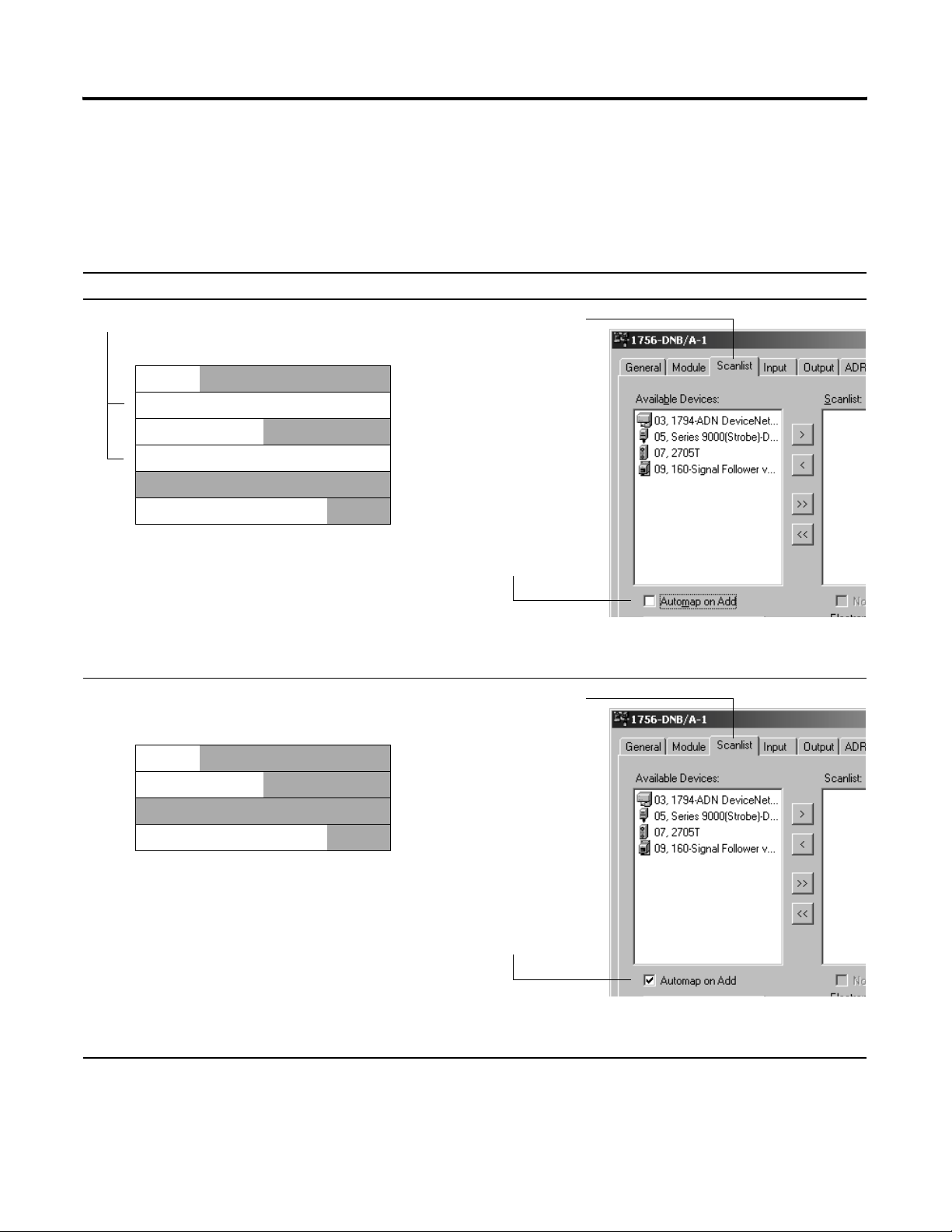
Clear or Set the Automap on Add Check Box
As an option, RSNetWorx software can automatically assign the
memory location for each device. Depending on how you want to
organize the memory, you may or may not want to use this option.
If you want to: Then:
Configure Your Network Online 6-13
leave gaps between devices
Memory
device at address 1
device at address 2
device at address 3
place devices in sequential DINTs
Memory
device at address 1
1. Click the Scanlist tab
2. Clear (uncheck) the
Automap on Add check box
After you add your devices to the scan list, manually assign the memory location
for each device.
1. Click the Scanlist tab
device at address 2
device at address 3
2. Set (check) the Automap on
Add check box.
As you add your devices to the scan list, the software automatically assigns the
memory locations for each device.
Publication DNET-UM004A-EN-P - March 2004
Page 92

6-14 Configure Your Network Online
Build the Scan List
1. You should be at the Scanlist tab
If you get the following warning for a device, see Set the I/O
Parameters of a Device on page 11-6
2. Add devices to the scan list.
To add: Do this:
devices one at a
time
all the devices
at once
Select a device and click the >
button.
Click the >> button.
.
Publication DNET-UM004A-EN-P - March 2004
Page 93

Configure Your Network Online 6-15
Manually Assign Each Device to a Memory Location
IMPORTANT
1. Click the Input tab.
2. Select the device.
If you used Automap on Add (page 6-13).as you built your scan list,
then skip this section. Each device already has a memory location.
3. Type the element number to which you want to assign the data. This is the
starting point for the data. Larger data sizes wrap to several elements.
For example, to start the data in …Data[3], type 3 in the
Start DWord box.
4. Choose AutoMap.
An entry for the device shows up in the input array.
5. Click the Output tab and repeat steps 2 - 4.
Sometimes, a specific input or output value may end up as the upper
bytes of a DINT in the scanner.
To make your programming easier, use advanced mapping to re-map
the value to its own memory location. For more information, see Give
a Value Its Own Memory Location on page A-1.
Publication DNET-UM004A-EN-P - March 2004
Page 94

6-16 Configure Your Network Online
Download the Configuration to the Scanner
Important: Make sure the scanner is in idle mode. To put the
scanner in idle mode, either:
• Turn off the …O.CommandRegister.Run bit of the scanner.
- or -
• Place the controller in program/remote program mode.
1. Apply the changes,
2. Yes, download.
3. Close the dialog box.
Upload and Save the Network File
1. Network ⇒ Upload from Network.
2. Yes, upload the entire network.
3. Save the file.
Once you configure the devices on your network, upload the entire
network and save the file. This stores the configuration of each device
in your offline file.
Publication DNET-UM004A-EN-P - March 2004
Page 95

Configure Your Network Online 6-17
Generate an RSNetWorx Report
1. File ⇒ Generate Report.
2. Entire network
An RSNetWorx report shows the following:
• devices on your network
• memory addresses of those devices in the scanner
• configuration of each device
The report is a very useful reference when you program your system.
The report shows up as an
HTML file.
Publication DNET-UM004A-EN-P - March 2004
Page 96

6-18 Configure Your Network Online
Notes:
Publication DNET-UM004A-EN-P - March 2004
Page 97

Control a Device
Chapter
7
How to Use This Chapter
Use this chapter to develop the logic that examines and controls your
devices.
Step: Page:
❑ Before You Use This Chapter 7-2
❑ Determine the Address of DeviceNet Data 7-7
❑ Program Your Logic With Alias Tags 7-10
❑ Determine If a Device Has Failed 7-11
❑ Place the Scanner in Run Mode 7-12
❑ When to Use a MSG Instruction 7-13
❑ Determine the Parameter Number to Access 7-13
❑ Determine the Configuration of the Parameter 7-14
❑ Test the Parameter 7-15
❑ Enter Message Logic 7-16
1 Publication DNET-UM004A-EN-P - March 2004
Page 98

7-2 Control a Device
Before You Use This Chapter
Before you use this chapter, get the following information:
RSNetWorx Report for Your Network
Data Map for Each of Your Devices
Publication DNET-UM004A-EN-P - March 2004
Page 99

Control a Device 7-3
Add the Scanner to the I/O Configuration of the Controller
To access the data of your network, add the scanner to the I/O
configuration of the controller.
To add a scanner:
Step: See page:
❑ If You Need to Conserve EtherNet/IP or ControlNet Network
Bandwidth
❑ Add the Scanner to the I/O Configuration Folder 7-5
❑ Define the Properties of the Scanner 7-6
7-3
If You Need to Conserve EtherNet/IP or ControlNet Network
Bandwidth
The default configuration of the scanner gives you the maximum
amount of input, output, and status data.
If the scanner communicates with the controller via an EtherNet/IP or
ControlNet network and you need to conserve bandwidth over that
network, consider reducing the input, output, or status sizes.
• Set the input and output sizes = the number of input and output
DINTs in the scanner that actually store device data.
• If you are not going to use all the status information, set the
status size to the minimum required. See Table 7.1 on page 7-4.
EXAMPLE
Set the status size for a scanner
• If you want to only use the ASCII representation
of scanner status/display, then set the
Status Size = 10.
• If you also want to read the status code of the
scanner, set the Status Size = 11.
Publication DNET-UM004A-EN-P - March 2004
Page 100

7-4 Control a Device
Table 7.1 Set the status size for a scanner
If you want this information: Set the Status
Size to (DINTs):
Which gives you:
Member: Data Type
count of I/O scans 10 ScanCounter DINT
indication that a device has failed:
DeviceFailureRegister SINT[8]
• There is 1 bit for each address on the DeviceNet network (0 -63).
• The position of a bit = address of a device.
• If a bit = 1, then the device at that address has failed.
indication that the data size of a device does not match the amount of
AutoverifyFailureRegister SINT[8]
memory allocated for the device in the scanner:
• There is 1 bit for each address on the DeviceNet network (0 -63).
• The position of a bit = address of a device.
• If a bit = 1, then their is a mismatch with that address.
indication that a device is idle:
DeviceIdleRegister SINT[8]
• There is 1 bit for each address on the DeviceNet network (0 -63).
• The position of a bit = address of a device.
• If a bit = 1, then the device at that address is idle.
indication that a device is online:
ActiveNodeRegister SINT[8]
• There is 1 bit for each address on the DeviceNet network (0 -63).
• The position of a bit = address of a device.
• If a bit = 1, then the device at that address is online.
ASCII representation of scanner status/display StatusDisplay SINT[4]
address of the scanner 11 ScannerAddress SINT
status code of scanner ScannerStatus SINT
address with an error:
ScrollingDeviceAddress SINT
• scrolls through the addresses with errors
• ScrollingDeviceStatus member shows the status code
status code of an address with an error:
ScrollingDeviceStatus SINT
• scrolls through addresses with errors
• ScrollingDeviceAddress member shows the address
possible future expansion of the structure – 5 DINTs 16
status code of lower 32 devices – 1 byte per device 24 DeviceStatus SINT[32]
status code of all devices – 1 byte per device 32 DeviceStatus SINT[64]
Publication DNET-UM004A-EN-P - March 2004
 Loading...