

Page 1
Installation Instructions
Original Instructions
Kinetix 5700 iTRAK Power Supply and iTRAK Bus Conditioner Module
Catalog Numbers 2198T-W25K-ER and 2198T-WBCMOD
Top ic Pa ge
Summary of Changes 1
Unpack 2
Parts List 2
Product Dimensions 3
Enclosure Requirements 4
Power Configuration 7
Install the iTRAK Power Supply 8
Drill Hole Patterns 9
Connector Data 10
Wiring Requirements 12
Wire the iTRAK Power Supply 14
Cable Preparation for iTRAK Power Supply Output Power Cables 16
Apply the iTRAK Power Cable Shield Clamp 20
Install the iTRAK Bus Conditioner Module 20
Power Wiring Examples 22
Commission 26
Fuse Replacement 27
Additional Resources 28
Summary of Changes
Change Page
Updated the section titled Bus Conditioner Module Mounting Options
(2198T-L16xx Motor Modules).
Added information to the Power Configuration section. 7
Updated wiring information. 22…26
5
Page 2

Kinetix 5700 iTRAK Power Supply and iTRAK Bus Conditioner Module Installation Instructions
The Kinetix® 5700 iTRAK® power supply with 458…747V DC input provides continuous output power and current to iTRAK motor modules by using two controlled DC outputs
with continuous current of 12.5 A and peak current of 25 A. The iTRAK bus conditioner module provides additional DC bus stiffness with local capacitance to the track. Use it
whenever you use iPS with medium frame iTRAK unless advised by Rockwell Automation.
See the Kinetix 5700 Servo Drives User Manual, publication 2198-UM 002
apply power, troubleshoot, and integrate with ControlLogix® EtherNet/IP communication modules or CompactLogix™ 5370 controllers.
and iTRAK System User Manual, publication 2198 T-UM 001 for detailed information on how to wire,
Unpack
Remove all packing material, wedges, and braces from within and around the components. After unpacking, check the item nameplate catalog number against the purchase
order.
Parts List
The iTRAK power supply ships with the following:
•DC bus-bar link, 100mm
• Wiring-plug connector set with 24V control input power (CP), digital inputs (IOD), iTRAK power supply ready (IR) output, two iTRAK 24V output (ICP), and two iTRAK
bus output (IDC) connectors
• These installation instructions, publication 2198T-IN001
Replacement connector sets are also available. See the iTRAK System Technical Data, publication 2198T-TD001, for more information.
The iTRAK bus conditioner module ships with the following:
• M6 x 1, 30 mm mounting screws, quantity 4.
Rockwell Automation Publication 2198T-IN001D-EN-P - October 2020 2
Page 3
Kinetix 5700 iTRAK Power Supply and iTRAK Bus Conditioner Module Installation Instructions
iPS RDY
MOD
NET
2
1
16
5
10
I/O
253
(9.96)
12.0
(0.47)
100
(3.94)
508
(20.0)
375
(14.8)
Dimensions are in mm (in.)
2198 T-W25K -ER
Kinetix 5700 iTRAK power supply is shown.
140
(5.5)
91
(3.6)
93
(3.7)
10
(0.4)
120
(4.7)
140
(5.5)
1500
(59.0)
Ø 15.19 ± 0.51
(Ø 0.598 ± 0.02)
127.0 mm (5.0 in.)
M6 x 1, 30 mm
Mounting Screws (X4)
Dimensions are in mm (in.)
Bend Radius
219 8T-WB CMOD
iTRAK Bus Conditioner Module is shown.
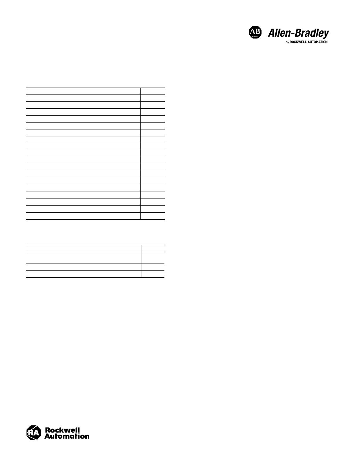
Product Dimensions
See the Kinetix Servo Drives Technical Data, publication KNX-TD003, for product dimensions of all Kinetix 5700 drive modules.
iTRAK Power Supply Dimensions
iTRAK Bus Conditioner Module Dimensions
Rockwell Automation Publication 2198T-IN001D-EN-P - October 2020 3
Page 4
Kinetix 5700 iTRAK Power Supply and iTRAK Bus Conditioner Module Installation Instructions
Clearance to the right of the
power supply is not required.
Clearance to the left of the
power supply is not required.
Kinetix 5700 iTRAK
Power Supply
100 mm (3.94 in.) clearance below the
power supply for airflow and installation.
40 mm (1.57 in.) clearance above the
power supply for airflow and installation.
See Product Dimensions
on page 3
for iTRAK power supply dimensions.
Clearance back of the bus
conditioner module is not required.
Clearance right of the bus
conditioner module is not required.
Clearance left of the bus conditioner
module is not required.
66 mm(2.6 in.) clearance above of the
bus conditioner module for installation.
175 mm(6.9 in.) clearance in front of the
bus conditioner module for cable routing.
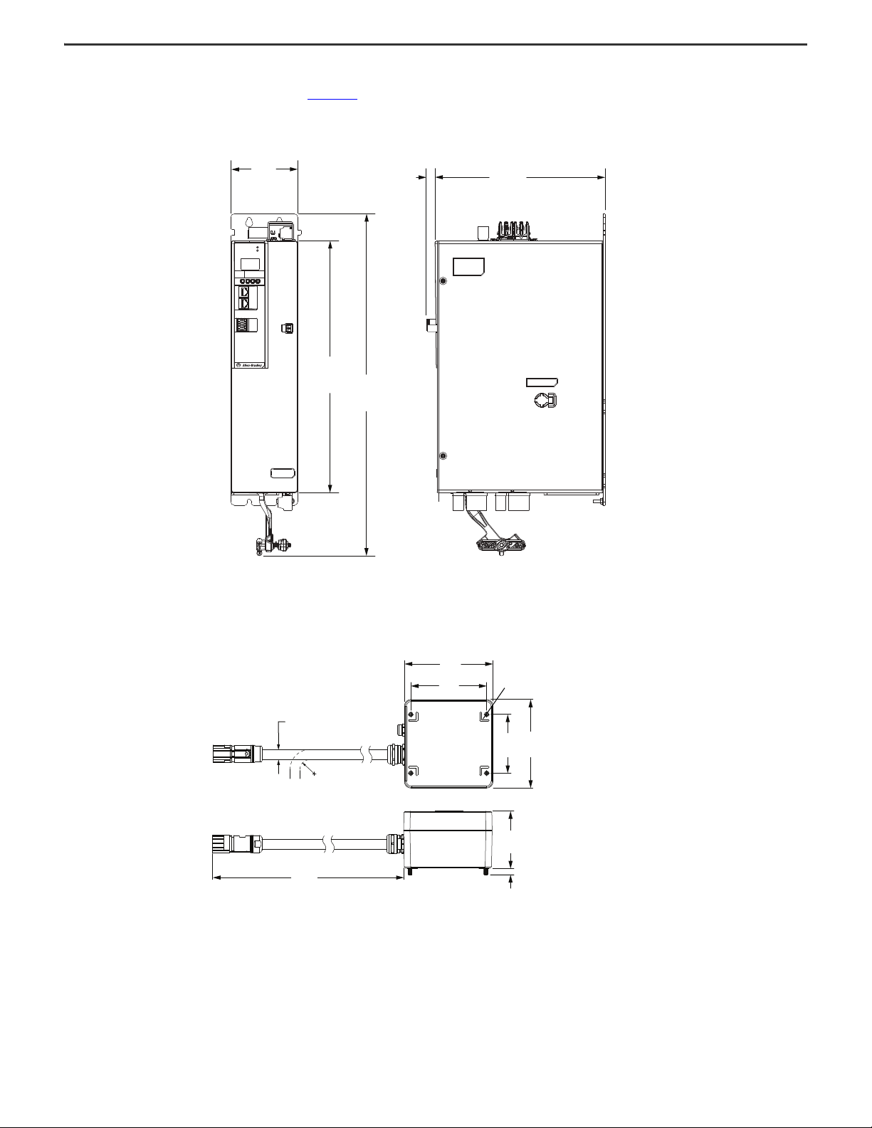
Enclosure Requirements
The recommended minimum cabinet depth is 300 mm (11.81 in.).
iTRAK Power Supply Minimum Clearance Requirements
Observe these additional clearance requirements when mounting the iTRAK power supply:
• Additional clearance is required for cables and wires or the shared-bus connection system that is connected to the top of the power supply.
• Additional clearance is required if other devices are installed above and/or below the power supply and have clearance requirements of their own.
• Additional clearance to the left and right of the power supply is required when mounted next to noise sensitive equipment or clean wireways.
IMPORTANT
Mount the iTRAK power supply in an upright position as shown. Do not mount the power supply on its side.
iTRAK Bus Conditioner Module Minimum Clearance Requirements
4 Rockwell Automation Publication 2198T-IN001D-EN-P - October 2020
Page 5
Kinetix 5700 iTRAK Power Supply and iTRAK Bus Conditioner Module Installation Instructions
396.2
(15.60)
320.6
(12.622)
Dimensions are in mm (in.)
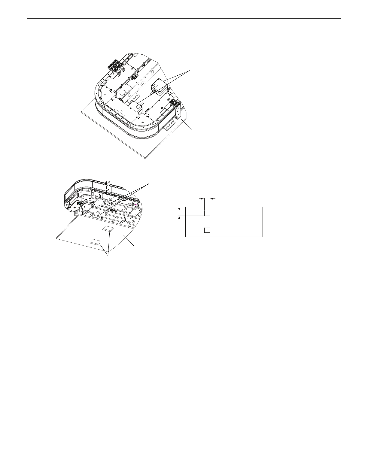
Base Plate
Bus Conditioner Module Access
Minimum Opening Dimensions
Bus Conditioner Modules
127
(5.0)
Dimensions are in mm (in.)
Base Plate
Bus Conditioner Module Cable Access
Minimum Cable Access Dimensions
Solid Base Plate
Mounting surface above track.
(Not shown).
Bus Conditioner Modules
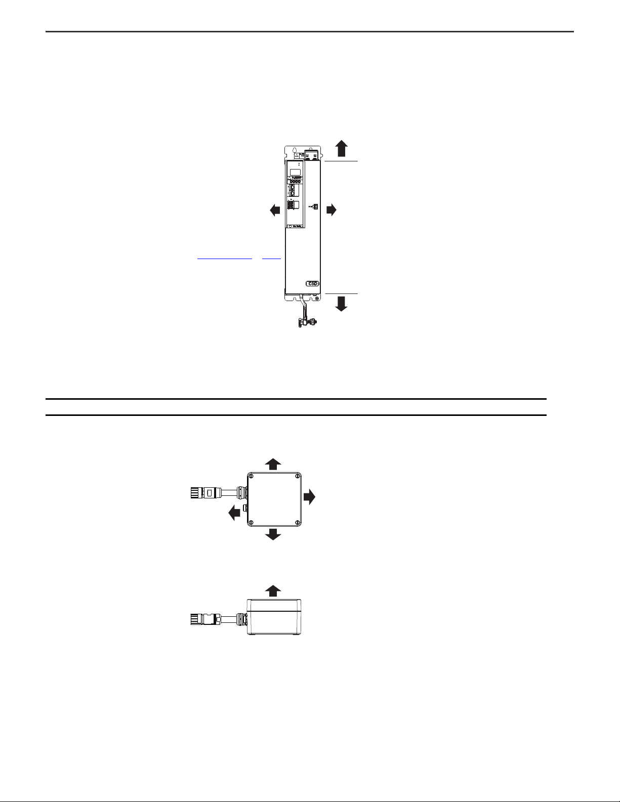
Bus Conditioner Module Mounting Options (2198T-L16xx Motor Modules)
We recommended that you use pre-drilled and tapped holes on the iTRAK spine bars for mounting the bus conditioner module. If your system configuration requires you to
relocate the bus conditioner module, here are other mounting options.
Mount Bus Conditioner Modules on an 2198T-Exxx800000, iTRAK System, 0.8 m (2.6 ft), Oval
Mount on Spine Bars (Recommended)
Mount Below Base Plate
Mount Above Track
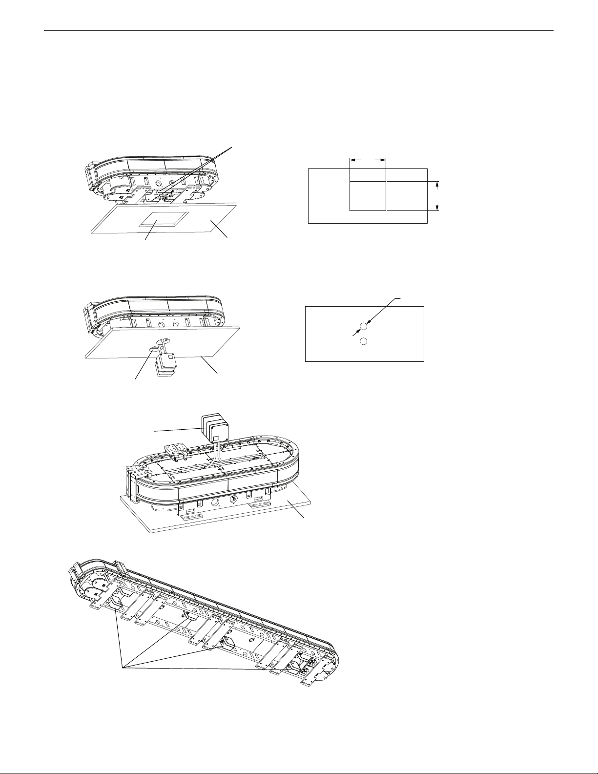
Mount Bus Conditioner Modules on an Oval Multi-section Open Frame iTRAK System
Rockwell Automation Publication 2198T-IN001D-EN-P - October 2020 5
Page 6
Kinetix 5700 iTRAK Power Supply and iTRAK Bus Conditioner Module Installation Instructions
Solid Base Plate
Bus Conditioner Modules
190.0
(7.48)
160.0
(5.905)
Dimensions are in mm (in.)
Base Plate
Bus Conditioner Module Access
Minimum Opening Dimensions
Bus Conditioner Modules
Mount Bus Conditioner Modules on an 2198T-Exxx800400, iTRAK System, 0.8 x 0.4 m (2.6 x 1.3 ft) Rectangle or Larger
Mount on Base Plate
Mount on Spine Bars
6 Rockwell Automation Publication 2198T-IN001D-EN-P - October 2020
Page 7
Kinetix 5700 iTRAK Power Supply and iTRAK Bus Conditioner Module Installation Instructions
Power Configuration
The iTRAK power supply can operate from any valid Kinetix 5700 input power configuration.
Grounding Screw
The grounding screw setting on the iTRAK power supply is dependent on the type of converter (DFE) and the source configuration, as shown in the following table. When
using L16 motor modules, only the grounded Y configuration is allowed.
Ground Screw/Jumper Setting for 2198-iTRAK Power Supply
iTRAK Power Supply Ground Jumper Setting
AC Power Source Type
Grounded (wye) Inverter ground screw/jumper installed.
• AC-fed ungrounded
• Corner grounded
• Impedance grounded
(1) 2198-Pxxx DC-bus power supply when 2198-DB20-F, 2198-DB42-F, 2198-DB80-F, or 2198-
DB290-F AC line filter is used.
Based on Selected Power Supply
2198-Pxxx
Inverter ground screw/jumper not installed.
(1)
DC-bus Power Supply
IMPORTANT
IMPORTANT
If you have grounded-wye power distribution and the 2198-Pxxx DC-bus power supply with:
• 2198-DB20-F, 2198-DB42-F, 2198-DB80-F, or 2198-DB290-F AC line filters, install the ground jumper in the iTRAK power supply. EMC
performance can be affected if the ground jumper is not installed.
• 2198-DBR20-F, 2198-DBR40-F, 2198-DBR90-F, or 2198-DBR200-F AC line filters, remove the ground jumper in the iTRAK power supply.
Ground jumper removed is preferred when using the 2198-DBRxx-F AC line filters. EMC performance is achieved with or without the
ground jumper installed.
EMC performance can be affected if you remove the grounding screw.
ATTENTION: If you remove the grounding screw, the risk of equipment damage exists because the unit no longer maintains line-to-neutral
voltage protection.
ATTENTION: To avoid personal injury, the grounding-screw access door must be kept closed when power is applied. If power was present,
and then removed, wait at least 5 minutes for the system voltage to dissipate, and verify that no voltage exists before accessing the
grounding screw.
SHOCK HAZARD: Avoid hazard of electrical shock; mount and wire the power supply before power is applied. Once power is applied,
connector terminals can have voltage present even when not in use.
Rockwell Automation Publication 2198T-IN001D-EN-P - October 2020 7
Page 8
Kinetix 5700 iTRAK Power Supply and iTRAK Bus Conditioner Module Installation Instructions
MOD
NET
MOD
NET
MOD
NET
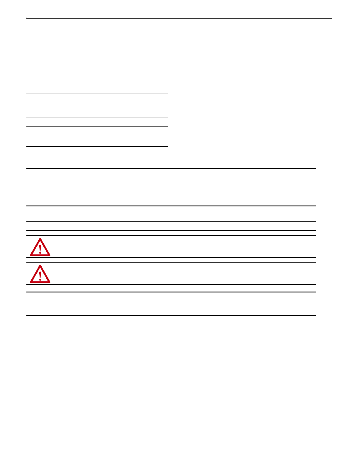
Zero-stack Tab
and Cutout
Aligned
Shared-bus connection system is not shown for clarity.
Install the iTRAK Power Supply
These procedures assume that you have prepared your panel and understand how to bond your system. For installation instructions regarding equipment and accessories
that are not included here, refer to the instructions that came with those products.
ATTENTION: Plan the installation of your system so that you can cut, drill, tap, and weld with the system that is removed from the enclosure.
Because the system is of the open type construction, be careful to keep any metal debris from falling into it. Metal debris or other foreign
matter can become lodged in the circuitry and result in damage to components.
System Mounting Requirements
• The iTRAK power supply must be enclosed in a grounded conductive enclosure that offers protection as defined in standard EN 60529 (IEC 529) to IP54 such that
they are not accessible to an operator or unskilled person. A NEMA 4X enclosure exceeds these requirements providing protection to IP66.
• The panel that you install inside the enclosure for mounting your system components must be on a flat, rigid, vertical surface that is not subjected to shock,
vibration, moisture, oil mist, dust, or corrosive vapors in accordance pollution degree 2 (EN 61800-5-1) because the product is rated to protection class IP20 (EN
60529).
Mount the iTRAK Power Supply
The iTRAK power supply must be spaced by aligning the zero-stack tab and cutout. To mount, size, and configure shared-bus configurations, see the Kinetix 5700 Servo
Drives User Manual, publication 2198-U M002
.
Mount the iTRAK power supply to the cabinet subpanel with M5 (#10-32) steel bolts that are torqued to 4.0 N•m (35.4 lb•in), max.
8 Rockwell Automation Publication 2198T-IN001D-EN-P - October 2020
Page 9
Kinetix 5700 iTRAK Power Supply and iTRAK Bus Conditioner Module Installation Instructions
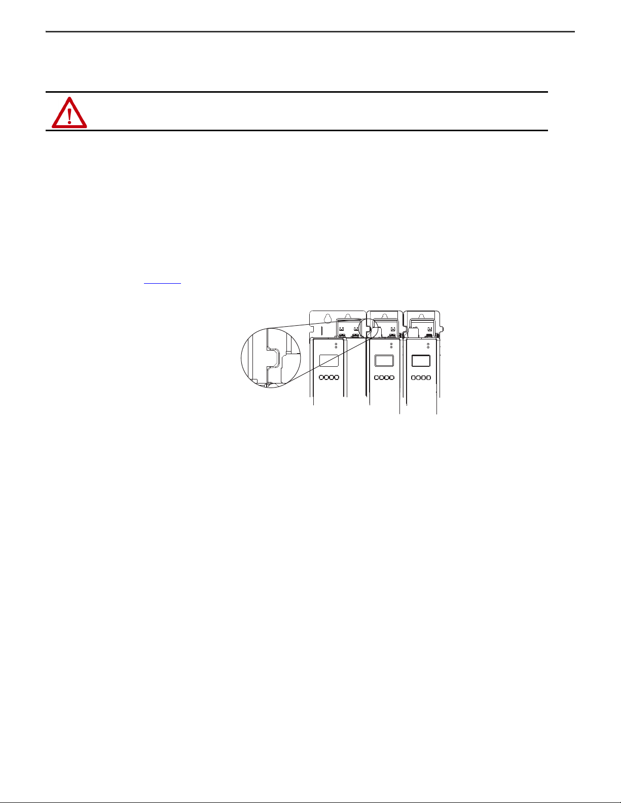
32.0 (1.26)
Module Top, reference
Dimensions are in mm (in.)
Module Top
465 (18.31)
Lower Mounting Hole
Ø 6.0 (0.24)
Typi cal
Ø 6.0 (0.24) Typical
00.0 (0.00)
Upper Mounting Holes
45.0 (1.77) See Mounting Hole Pattern Calculations
30.0 (1.18) See Mounting Hole Pattern Calculations
100 mm
Wide Module
85 mm
Wide Module
55 mm
Wide Module
55 mm
Wide Module
Applies to only 2198-S160-ERS3
Single-axis Inverter
Applies to 2198-Pxxx Power Supplies,
2198-S086-ERS3 and 2198-S130-ERS3 Inverters,
and 2198-Dxxx-ERS3 Inverters
Applies to 2198-Pxxx Power Supplies
2198 -Dxxx-ERS3 Inverters, and 2198-CAPMOD2240
First Mounting Hole
(typical) Upper and Lower
Mounting Hole
(all drive modules)
Applies to only 2198-CAPMODDCBUS-IN Extension Module
45.0 (1.77) See Mounting Hole Pattern Calculations
100 mm
Wide Module
Applies to only 2198T-W25K-ER
iTRAK Power Supply
Drill Hole Patterns
This section provides hole patterns for Kinetix 5700 drives and power supplies that are mounted in zero-stack (shared-bus) configurations.
The iTRAK power supply is always mounted to the right of the Kinetix 5700 DC-bus power supply.
Calculate the left-to-right hole pattern for any Kinetix 5700 drive configuration by following these steps.
1. The first hole location is zero.
2. The second hole location is module width minus 55 mm (2.17 in.).
3. The next hole location is 55 mm (2.17 in.).
4. Repeat step 2 and step 3 for the remaining holes.
Kinetix 5700 Mounting Hole Patterns
The Kinetix 5700 System Mounting Toolkit, catalog number 2198-K5700-MOUNTKIT, is available to assist you with mounting holes.
Rockwell Automation Publication 2198T-IN001D-EN-P - October 2020 9
Page 10

Kinetix 5700 iTRAK Power Supply and iTRAK Bus Conditioner Module Installation Instructions
iTRAK Power Supply
(top view)
iTRAK Power Supply
(bottom view)
iTRAK Power Supply
(front view)
3
4
6
5
14
20
15
19
18
17
16
13
12
11
10
9
8
7
6
1
2
Connector Data
Use this illustration to identify the iTRAK power supply features and indicators.
iTRAK Power Supply Features and Indicators (2198T-W25K-ER)
MOD–
NET–
5700
2
1
I/O
1 6
-
IPS RDY
510
+
IN 24V -
IN 24V +
DC+
DC-
Item Description Item Description Item Description
1 Power bus cable clamp 8 Network status indicator 15 24V control input power (CP) connector
2 Ground lug 9 LCD display 16 24V control output power (ICP) connector -A
3 Digital inputs (IOD) connector 10 Navigation push buttons 17 DC bus output (IDC) connector - A
4 Ethernet (PORT1) RJ45 connector 11 Link speed status indicators 18 24V control output power (ICP) connector - B
5 Ethernet (PORT2) RJ45 connector 12 Link/Activity status indicators 19 DC bus output (IDC) connector - B
6 Zero-stack mounting tab/cutout 13 iTRAK power supply ready (IR) 20 Cooling fan
7 Module status indicator 14 DC bus input (DC) connector
10 Rockwell Automation Publication 2198T-IN001D-EN-P - October 2020
Page 11

Kinetix 5700 iTRAK Power Supply and iTRAK Bus Conditioner Module Installation Instructions
Control Input Power (CP) Connector
Control Output Power A and B (ICP)
Connectors
-
+
H L DC-
iTRAK Power Supply Connectors
Designator Description Connector
DC DC common bus power DC-bus links and end caps
CP 24V control input power 2-position plug, terminal screws
IDC iTRAK DC bus output A and B 4-position plug, terminal screws
ICP iTRAK 24V control output power A and B 2-position plug, terminal screws
IOD Digital inputs 10-position plug, spring terminals
IR iTRAK power supply ready 2-position plug, terminal screws
PORT1, PORT2 Ethernet communication ports RJ45 Ethernet
DC Bus Input Power Connector
DC Pin Description Signal
Bus bar DC bus connections
DC–
DC+
Control Input Power (CP) and Control Output Power A and B (ICP) Connectors Pinout
2
Pin Description Signal
2 24V common 24V1 24V power supply, customer-supplied 24V+
1
2 1
iTRAK Power Supply Ready (IR) Connector Pinout
IR Pin Description Signal
2
1RDY+
iTRAK power supply ready
RDY-
DC Power Bus Output A and B (IDC) Connectors Pinout
IDC Pin Description Signal
4Chassis ground GND
3 DC high voltage H
2 DC low voltage L
1 DC-bus DC-
Digital Inputs (IOD) Connector Pinout
IOD Pin Description Signal
1 Digital input #1 Enable
2
3 Digital input #2 Fault Clear
4
5 I/O cable shield termination point SHLD
6 Digital input #3 IN3
7
8 Digital input #4 IN4
9
10 I/O cable shield termination point SHLD
I/O common for customer-supplied 24V
supply
I/O common for customer-supplied 24V
supply
I/O common for customer-supplied 24V
supply
I/O common for customer-supplied 24V
supply
COM
COM
COM
COM
1
2
3
4
5
6
7
8
9
10
Rockwell Automation Publication 2198T-IN001D-EN-P - October 2020 11
Page 12

Kinetix 5700 iTRAK Power Supply and iTRAK Bus Conditioner Module Installation Instructions
Wiring Requirements
The wire must be copper with 75 C (167 F) minimum rating. Phasing of mains AC power is arbitrary and earth ground connection is required for safe and proper operation.
IMPORTANT
The National Electrical Code and local electrical codes take precedence over the values and methods provided.
iTRAK Power Supply (2198T-W25K-ER) Wiring Requirements
Description
DC-bus input power Bus bar
SELV/PELV rated 24V power
(connector plug)
iTRAK power supply ready
24V iTRAK control power
DC-bus output power A and B
Digital inputs
(1) Shared DC-bus power connections are always made from power supply to power supply over the bus-bar connection system. These terminals do not recei ve
discrete wires .
(2) Use sufficient wire size to support the complete control power load, including Kinetix 5700 modules and pass-through current for the attached motor modules.
(3) The iTRAK control power (ICP) and iTRAK DC bus output (IDC) connections must be made using catalog number 2198T-CHBFLS8-12AAxx.
(4) This connector uses spring tension to hold wires in place.
Connects to Terminals
Pin Signal
CP-1
CP-2
IR-1
IR-2
ICP-1
(3)
ICP-2
IDC-1
IDC-2
(3)
IDC-3
IDC-4
IOD-1
IOD-2
IOD-3
IOD-4
IOD-5
IOD-6
IOD-7
IOD-8
IOD-9
IOD-10
DC–
DC+
24V+
24V–
RDY+
RDY-
24V+
24V–
DCL
H
GND
Enable
COM
Clear Fault
COM
SHLD
IN3
COM
IN4
COM
SHLD
Wire Size
mm² (AWG)
(1)
N/A
(2)
1.5…4
(16…12)
(2)
6
(10)
0.05…2.5
(30…12)
1.5…6
(16…10)
2.5…6.0
(12…10)
0.20…1.31
(24…16)
Strip Length
mm (in.)
(1)
N/A
10.0 (0.39)
10.0 (0.39)
7.0 ( 0.28)
10.0 (0.39)
10.0 (0.39)
10.0 (0.39)
Tor que Val ue
N•m (lb•in)
(1)
N/A
0.5…0.6
(4.4…5.3)
0.7…0.8
(6.1…7.0)
0.4…0.5
(3.5…4.4)
0.7…0.8
(6.1…7.0)
0.7…0.8
(6.1…7.0)
(4)
N/A
ATTENTION: To avoid personal injury and/or equipment damage, observe the following:
• Make sure that installation complies with specifications regarding wire types, conductor sizes, branch circuit protection, and disconnect
devices. The National Electrical Code (NEC) and local codes outline provisions for safely installing electrical equipment.
• Use motor power connectors only for connection purposes. Do not use them to turn on or off the unit.
• Ground shielded power cables to prevent potentially high voltages on the shield.
12 Rockwell Automation Publication 2198T-IN001D-EN-P - October 2020
Page 13

Kinetix 5700 iTRAK Power Supply and iTRAK Bus Conditioner Module Installation Instructions
Braided Ground Straps
12 mm (0.5 in.) by 0.8 mm (0.03 in.)
Keep straps as short as possible.
4
3
2
1
iTRAK Power Supply
(typical example)
Kinetix 5700 Servo
Drives
(typical system)
Ground the Power Supply to the Subpanel
Ground Kinetix 5700 iTRAK power supply to a bonded-cabinet ground bus with a braided ground strap. Keep the braided ground strap as short as possible for optimum
bonding.
Connect the Braided Ground Strap
Item Description
1 Ground screw (green) 2.0 N•m (17.5 lb•in), max
2 Braided ground strap (customer supplied)
3 Ground grid or power distribution ground
4 Bonded-cabinet ground bus (customer supplied)
Rockwell Automation Publication 2198T-IN001D-EN-P - October 2020 13
Page 14

Kinetix 5700 iTRAK Power Supply and iTRAK Bus Conditioner Module Installation Instructions
iPS RDY
MOD
NET
2
1
16
5
10
I/O
1
2
3
4
5
6
7
8
9
10
2198 T-W25- ER
iTRAK Power Supply
(front view)
Digital Input Connector Plug
Wire the iTRAK Power Supply
The following sections cover wiring the iTRAK power supply to an iTRAK system.
For information on how to wire to the input control power (CP) connector and connect the DC-power bus links, see the Kinetix 5700 Servo Drives User Manual, publication
2198 -UM00 2
Wire the Digital Input Connector
The digital inputs are part of a required I/O interface with the gateway. The digital inputs are connected to the gateway through the digital
USB I/O module.
Digital Input Connector Wiring
.
Digital Input Connector Plug Specifications
Description Pin Signal
IOD-1
Digital inputs
See Connect an iTRAK Power Supply to a System on page 22 for wiring diagram information.
IOD-2
IOD-3
IOD-4
IOD-5
Enable
COM
Clear Fault
COM
SHLD
Recommended
Wire Size
mm² (AWG)
0.20…1.31
(24…16)
Strip Length
mm (in.)
10.0 (0.39)
14 Rockwell Automation Publication 2198T-IN001D-EN-P - October 2020
Page 15

Kinetix 5700 iTRAK Power Supply and iTRAK Bus Conditioner Module Installation Instructions
iPS RDY
MOD
NET
2
1
16
5
10
I/O
-
+
2198 T-W25- ER
iTRAK Power Supply
(front view)
iTRAK PS Ready (IR) Connector Plug
Wire the iTRAK PS Ready (IR) Connector
The iTRAK PS relay output is part of a required I/O interface with the gateway and is connected to the gateway through the digital USB I/O module.
iTRAK PS Ready (IR) Connector Wiring - Connector Plug
iTRAK PS Ready (IR) Connector Plug Specifications
Description Pin Signal
iTRAK power supply
ready
See Connect an iTRAK Power Supply to a System
21+
Recommended Wire Size
mm² (AWG)
0.14…2.5
(26…12)
Strip Length
mm (in.)
7.0 ( 0.28 )
on page 22 for wire diagram information.
Tor que Val ue
N•m (lb•in)
0.4…0.5
(3.5…4.4)
Rockwell Automation Publication 2198T-IN001D-EN-P - October 2020 15
Page 16

Kinetix 5700 iTRAK Power Supply and iTRAK Bus Conditioner Module Installation Instructions
138 mm (5.43 in.)
Can be longer and trimmed at end
remove outer jacket only.
Trim filler material.
43 mm (1.7 in.)
32 mm
(1.26 in.)
Dimensions are in mm (in.)
Pull shielded twisted pair free by
forming an opening and thread it
back through the carefully expanded
shield.
Exposed twisted shielded pair is
stripped to the shield and the two
shields are in contact.
(Rotated View)
Cable Preparation for iTRAK Power Supply Output Power Cables
Follow these instructions to prepare the wires to create custom length 2198T-CHBFLS8-12Axx cables.
These instruction steps assume that the cable has already been cut to the desired length.
1. Mark the cable at 138 mm (5.4 in.) from the end.
2. Carefully cut away the outer jacket at the mark.
Be mindful not to damage the braided shield underneath.
3. Measure 32 mm (1.26 in.) from where the outer jacket ends and cut and remove the braided metal shield.
Save the braided metal piece that was trimmed for use in step 8
.
4. Measure 75 mm (3 in.) from where the outer jacket ends or 43 mm (1.7 in.) from where the shield ends, and trim the blue filler material.
5. Pull back the outer braided shield and carefully create an opening in the braid as close as possible to where the outer jacket ends.
6. Feed the internal shielded twisted pair through the opening in the outer braided shield, and pull it through tight.
The shielded twisted pair is now outside of the main braided shield and the two shields are in contact.
16 Rockwell Automation Publication 2198T-IN001D-EN-P - October 2020
Page 17

Kinetix 5700 iTRAK Power Supply and iTRAK Bus Conditioner Module Installation Instructions
Bundle wires with the previously
trimmed filler material into a
diameter approximately 8 mm
(0.32 in.) and cover with heat shrink.
75 mm
(3 in.)
Dimensions are in mm (in.)
75 mm
(3 in.)
Slide expanded tubular braids over
all conductors butt up to cable jacket
and pull tight.
Dimensions are in mm (in.)
Adhesive lined heat shrink two
places.
64 mm
(2.5 in.)
75 mm
(3 in.)
138 mm
(5.4 in.)
35 mm
(1.4 in.)
23 mm
(0.9 in.)
Jacket
Dimensions are in mm (in.)
7. To hold the wires together, bundle the group of four wires with the previously trimmed filler material and slip on a 45 mm (1.8 in.) length piece of shrink tube.
8. Slide previously trimmed piece of the outer braided shield over the entire bundle, butt it up to the cable jacket, pull tight, then trim the piece so it is approximately
75 mm (2.9 in.) long.
9. Place a 64 mm (2.5 in.) length of adhesive-lined shrink tube over the cable located 113 mm (4.4 in.) from the end of the wires.
10. Place a 23 mm (0.9 in.) length piece of adhesive-lined shrink tube over the cable so that a 35 mm (length of shielded braid is left exposed.
11. Trim the braided shield on the twisted-pair shield back 40 mm (1.6 in.) from the end of the wires.
12. Place a 20 mm (0.79 in.) length piece of shrink tube over the twisted pair approximately 30 mm (1.18 in.) from the end of the wires.
Rockwell Automation Publication 2198T-IN001D-EN-P - October 2020 17
Page 18

Kinetix 5700 iTRAK Power Supply and iTRAK Bus Conditioner Module Installation Instructions
64 mm
(2.5 in.)
138 mm
(5.4 in.)
35 mm
(1.4 in.)
23 mm
(0.9 in.)
Ring cut
insulation six
places.
9 ± 0.1 mm
(0.5 ± 0.004 in.)
20 mm (0.787 in.) long heat
shrink over twisted pair.
30 mm
(1.18 in.)
13 mm
(0.5 in.)
Jacket
Label wires 6
places.
Heat
Shrink
Exposed
Shield
Heat
Shrink
9 ± 0.1 mm
(0.5 ± 0.004 in.)
Dimensions are in mm (in.)
13. Strip the individual wires back 9 mm (0.35 in.)
Label wire with the signal names as shown here.
Power Supply Wire Labels
Color Gauge Signal
Brown
Black L
Blue DCGreen/Yellow PE
Red
White -24V
12
14
H
+24V
18 Rockwell Automation Publication 2198T-IN001D-EN-P - October 2020
Page 19

Kinetix 5700 iTRAK Power Supply and iTRAK Bus Conditioner Module Installation Instructions
H L DC-
2 1
H L DC-
2 1
2198 T-W2 5K-ER
iTRAK Power Supply
(right side view)
2198 T-W2 5K-ER
iTRAK Power Supply
(right side view)
iTRAK DC Bus
Output Connector Plugs
(ICP A)
(IDC B)
(ICP B)
(IDC A)
iTRAK Control Power
Output Connector Plugs
2198 T-W25K -ER
iTRAK Power Supply
(bottom view)
Wire the iTRAK Power Supply DC Bus and Control Power Output Connectors
The iTRAK power supply uses one cable, 2198T-CHBFLS8-12AAxx, to connect to the iTRAK system. The single cable terminates at two connectors on the iTRAK power supply:
one for iTRAK control power (ICP) and one for iTRAK DC bus power (IDC). Two sets of these connectors, referenced as A and B, are provided on the iTRAK power supply to
allow using two cables for larger iTRAK systems.
ATTENTION: Make sure that the iTRAK power connections are correct when wiring the plugs and that the plug is fully engaged in the module
connector. Incorrect wiring, polarity, or loose wiring can cause an explosion or damage equipment.
Choose a cable length that is appropriate for your application requirements. You can create custom cable lengths by cutting a 2198T-CHBFLS8- 12Axx to length, remove the
flying lead end and preparing new leads. See Cable Preparation for iTRAK Power Supply Output Power Cables
IDC and ICP Connector Wiring
on page 16 for instructions.
IDC and ICP Connector Wiring
Description
24V iTRAK control power
DC-bus output power A and B
(1) The iTRAK control power (ICP) and iTRAK DC bus output (IDC) connections must be made using catalog number 2198T-CHBFLS8-12AAxx.
White
Red
Green/Yellow
Brown
Black
Blue
Wire Size
mm² (AWG)
1.5…6
(16…10)
2.5…6.0
(12…10)
Strip Length
mm (in.)
10.0 (0.39)
10.0 (0.39)
Torqu e Valu e
N•m (lb•in)
0.7…0.8
(6.1…7.0)
0.7…0.8
(6.1…7.0)
Connects to Terminals
Pin Signal Wire Color
ICP-1
(1)
ICP-2
IDC-4
IDC-3
(3)
IDC-2
IDC-1
24V+
24V–
GND
H
L
DC-
Rockwell Automation Publication 2198T-IN001D-EN-P - October 2020 19
Page 20

Kinetix 5700 iTRAK Power Supply and iTRAK Bus Conditioner Module Installation Instructions
Cover Captive Screws
Ground Wire
Apply the iTRAK Power Cable Shield Clamp
Factory-supplied 2198T-CHBFLS8-12AAxx iTRAK cables are shielded. The braided cable shield must terminate at the iTRAK power supply when installed. A small portion of the
cable jacket has been removed to expose the shield braid. The exposed area must be clamped by using the clamp on the bottom front of the iTRAK power supply.
This procedure assumes that you have completed wiring your IDC and ICP connectors and are ready to apply the cable shield clamp.
To apply the iTRAK power-supply cable-shield clamp, do the following.
1. Loosen the clamp knob.
2. Position the exposed portion of each cable braid directly in line with the clamp.
3. Hand tighten the clamp knob.
Only finger-tight torque on the clamp knob is required. The cable must not move within the clamp under its own weight or when slight pressure is applied by
hand.
Install the iTRAK Bus Conditioner Module
If you have a 2198T-ExxxxxxxxxxxxxxxC iTRAK system, the bus conditioner module is already installed.
To install the iTRAK bus conditioner module, do the following.
1. Determine the location for the bus conditioner module.
We recommended that you use the pre-drilled and tapped holes on the iTRAK spine bars for mounting the bus conditioner module. If your system configuration
requires you to relocate the bus conditioner module see Bus Conditioner Module Mounting Options (
2. To gain access to the bus conditioner module mounting holes, remove the cover by loosening the four screws that attach the cover to the bus conditioner module
enclosure.
2198T-L16xx Motor Modules) on page 5.
These screws are captive and remain with the cover.
IMPORTANT
Four M6 x1, 30 mm long screws are shipped with the bus conditioner module. Use these screws to mount the bus conditioner module.
A ground wire connects the cover to the enclosure. When removing the cover, be careful not to stress the ground wire and do
not disturb any of the wiring or components within the bus conditioner module enclosure.
20 Rockwell Automation Publication 2198T-IN001D-EN-P - October 2020
Page 21

Kinetix 5700 iTRAK Power Supply and iTRAK Bus Conditioner Module Installation Instructions
Pre-drilled and tapped
mounting holes in the spine bar
(X4).
M6 x1, 30 mm long mounting
screws (X4)
Alignment standoff that is on the side
opposite of the connector and it fits
between the capacitors.
The ground wire that connects
to the cover of the enclosure is
routed around on the
perimeter of the enclosure and
the capacitors.
3. Orient the bus conditioner module on over the four mounting holes in the iTRAK spine bar as shown.
4. Apply Loctite 222 to the four M6 x1, 30 mm screws.
5. Insert the four screws and torque them to 2.5…3 N•m (1.8…2.2 lb•ft)
6. Replace the bus conditioner module cover by routing the ground wire as shown while installing the cover.
IMPORTANT
The cover must be oriented correctly for proper installation. Incorrect installation causes an improper environmental seal. To
aid in correct orientation, the cover does not lie flush when incorrectly placed.
7. Torque the four screws to 2.5…3 N•m (1.8…2.2 lb•ft).
8. Route and connect the bus conditioner module cable to the iTRAK motor module by using the example that is shown.
Rockwell Automation Publication 2198T-IN001D-EN-P - October 2020 21
Page 22

Kinetix 5700 iTRAK Power Supply and iTRAK Bus Conditioner Module Installation Instructions
+24V
24V_COM
+24V
24V_COM
1
2
DC+
DC-
DC+
DC-
DC+
SH
1
2
3
4
5
24V COM
(2)
24V COM
(2)
SHIELD
24V
24V
24V COM
DC-
L
H
L3 L2 L1
EN–
EN+
CONT EN–
CONT EN+
IN1
COM
IN2
SHLD
1
2
3
4
COM
COM
SHLD
1
2
1
2
DC-
L
H
DC-
L
H
DC-
L
H
A
B
OUT 00 NO
OUT 00 C
OUT 01 NO
OUT 01 C
IN00 A
IN00 B
24V +
24V -
24V +
24V -
+
-
RDY+
RDY-
IPS READY
ENABLE
CLEAR
FAULT
24V
Bonded Cabinet
Ground Bus
(1)
Control Power
(CP) Con nectors
Three-phase Input
(IPD) Connector
Connect to
three-phase
power input
Chassis
Customer Supplied
+24V DC
Power Su pply
(1)
DC Bus
(DC) Connectors
2198-Pxxx
Kinetix 5700
DC-bus Power Supply
2198T-W25K-ER
Kinetix 5700 iTRAK Power
Supply
PE Ground
Contac tor Enabl e
(CED) Co nnector
Optional
2198T-W25K-P-T
T-connectors and Bus Bars
PE Ground
Bonded Cabinet
Ground Bus
(1)
Shunt Power
(RC) Connector
DC Power Bus A
to iTRAK
Motor Modules
DC Power Bus A
(IDC) Connector
Cable Shie ld
Clamp
Digital Input
(IOD) Connector
Digital Input
(IOD) Connector
Optional
2198-TCON-24VDCIN36
24V Input Power
Wiring Connector
DC Power Bus B
to iTRAK
Motor Modules
Control Po wer A
to iTRAK
Motor Modules
Control Po wer B
to iTRAK
Motor Modules
Connec t
contactor enable
circuitry
(1)
USB I/O
iTRAK Power Supply
Ready (IR) Connector
DC Power Bus B
(IDC) Connector
(1) Customer supplied.
(2) Make only one of these 24V COM
DC Bus Bar
100 mm link
Do not connect DC Power Bus A and B in
parallel to another iTRAK power supply
on the same daisy chain.
For multiple iTRAK power
supplies, See Wiring Multiple
iTRAK Medium Frame Power
Supplies to the USB I/O on
page 25
Power Wiring Examples
ATTENTION: Capacitors on the DC bus can retain hazardous voltages after input power has been removed. Before working on the iTRAK
power supply, wait the full-time interval as indicated in the warning on the power supply. Failure to observe this precaution could result in
severe bodily injury or loss of life.
Use the following wiring diagrams to connect your iTRAK power supply.
Connect an iTRAK Power Supply to a System
22 Rockwell Automation Publication 2198T-IN001D-EN-P - October 2020
Page 23

Kinetix 5700 iTRAK Power Supply and iTRAK Bus Conditioner Module Installation Instructions
1
2
3
4
5
24V COM
(1)
24V COM
(1)
SHIELD
24V
24V
24V
24V COM
COM
COM
SHLD
OUT 00 NO
OUT 00 C
OUT 01 NO
OUT 01 C
IN00 A
IN00 B
1
2
3
4
24V COM
(1)
24V COM
(1)
SHIELD
-
+
RDY-
RDY+
RDY-
RDY+
ENABLE
CLEAR
FAULT
COM
COM
SHLD
ENABLE
CLEAR
FAULT
2198T-GUSB
Digital USB I/O
Module
2198T-W25K-ER
Kinetix 5700 iTRAK
Power Supply 2
Digital Input
(IOD) Connector
ITRAK Power Supply
Ready (IR) Connector
ITRAK Power Supply
Ready (IR) Connector
2198T-W25K-ER
Kinetix 5700 iTRAK
Power Supply 1
Digital Input
(IOD) Connector
USB
Port
2198-Pxxx
Kinetix 5700
Power Supply
2198T-W25K-ER
Kinetix 5700
iTRAK Power
OutputAOutput
B
1
1
2
4
2
24
3
3
3
22 2 222
3
2222
One gateway can interface to multiple iTRAK power supplies through the Dig
ital USB I/O Module. When you use this configuration, connect the Enable and Clear Fault signals
in parallel, and connect the IPS Ready signal in series through all iTRAK power supplies as shown in the following diagram. Wiring Multiple iTRAK Power Supplies to the Digital
USB I/O Module.
1
Only one connection to 24V Com is required for each iTRAK power supply. Either pin 2 or pin 4 must be connected, it is not necessary to connect both.
Wire an iTRAK Power Supply and iTRAK Bus Conditioner Modules to an iTRAK Medium Frame System
Rockwell Automation Publication 2198T-IN001D-EN-P - October 2020 23
Page 24

Kinetix 5700 iTRAK Power Supply and iTRAK Bus Conditioner Module Installation Instructions
2198-Pxxx Kinetix
5700 Power Supply
2198T-W25K-ER
Kinetix 5700
iTRAK Power Supply 1
Output
B
Output
A
Output
B
2198T-W25K-ER
Kinetix 5700
iTRAK Power Supply 2
Output
A
1
3
3
2
2
4
4
42
1
3
32 2
222
3
1
2198-Pxxx
Kinetix 5700
Power Supply
2198T-W25K-ER
Kinetix 5700
iTRAK Power
Supply 1
Output
A
Output
B
2198T-W25K-ER
Kinetix 5700
iTRAK Power
Supply 2
OutputAOutput
B
Wire Multiple iTRAK Power Supplies and iTRAK Bus Conditioner Modules to an iTRAK Medium Frame System
Item Description
1 2198T-CHBFLS8-12AAxx, iTRAK power supply to motor module cable
2 2198T-CHBP8S8-12P3, power cable
3 2198T-CHBP8S8-12P6, power cable
42198T-WBCMOD, iTRAK bus conditioner module
ATTENTION: Power from iTRAK power supply 1 must not be connected to the power from iTRAK power supply 2.
24 Rockwell Automation Publication 2198T-IN001D-EN-P - October 2020
Page 25

Kinetix 5700 iTRAK Power Supply and iTRAK Bus Conditioner Module Installation Instructions
1
2
3
4
5
24V COM
(1)
24V COM
(1)
SHIELD
24V
24V
24V
24V COM
COM
COM
SHLD
OUT 00 NO
OUT 00 C
OUT 01 NO
OUT 01 C
IN00 A
IN00 B
1
2
3
4
24V COM
(1)
24V COM
(1)
SHIELD
-
+
RDY-
RDY+
RDY-
RDY+
ENABLE
CLEAR
FAULT
COM
COM
SHLD
ENABLE
CLEAR
FAULT
USB I/O
2198T-W25K-ER
Kinetix 5700 iTRAK Power
Supply
Digital Input
(IOD) Connector
ITRAK Power Supply
Ready (IR) Connector
ITRAK Power Supply
Ready (IR) Connector
2198T-W25K-ER
Kinetix 5700 iTRAK Power
Supply
Digital Input
(IOD) Connector
Wiring Multiple iTRAK Medium Frame Power Supplies to the USB I/O
When multiple iTRAK power supplies are connected to the same 2198-Pxxx DC-bus power supply, follow these guidelines.
• Connect each iTRAK power supply to the same USB I/O module.
• Connect each iTRAK Power Supply Ready relay output string serially through all iTRAK power supplies.
• Connect the OUT 00 NO output on the USB I/O module to the ENABLE input of all iTRAK power supplies.
• Connect the OUT 01 NO output from the USB I/O module to the CLEAR FAULT input of all iTRAK power supplies.
Using Multiple iTRAK Power Supplies with the 5730 System
When using multiple iTRAK power supplies in an iTRAK system, follow these guidelines.
• When using multiple iTRAK power supplies, the system must be parsed into separate electrical pieces for each of the iTRAK power supplies.
• The iTRAK power supply is not designed to have the output buses of multiple power supplies connected together to create one bus of higher current capacity.
IMPORTANT
Use the following scenario to understand the use of multiple iTRAK power supplies for systems that require a higher current draw. In this example, part of the track has a
high-power demand, and the rest of the track has a lower power demand. In this case iTRAK power supply 1 powers the first group of ten motor modules, while iTRAK power
supply 2 provides power to the remaining six motor modules. The DC buses of these two groups are electrically isolated from each other as shown in the diagram.
In systems that use multiple iTRAK power supplies, make sure that the output bus of one power supply is never connected to the output bus
of another power supply.
Rockwell Automation Publication 2198T-IN001D-EN-P - October 2020 25
Page 26

Kinetix 5700 iTRAK Power Supply and iTRAK Bus Conditioner Module Installation Instructions
2198-Pxxx
Kinetix 5700
Power S upply
2198T-W25K-ER
Kinetix 5700
iTRAK Power
Supply 1
Output
A
2198T-W25K-ER
Kinetix 5700
iTRAK Power
Supply 2
OutputBOutputAOutput
B
1
3
3
2
2
2
1
3
32 2
222
3
1
Connecting Multiple iTRAK Power Supplies in a System
Item Description
1 2198T-CHBFLS8-12AAxx, iTRAK power supply to motor module cable
2 2198T-CHBP8S8-12P3, power cable
3 2198T-CHBP8S8-12P6, power cable
ATTENTION: Power from iTRAK power supply 1 must not be connected to the power from iTRAK power supply 2.
Commission
To assist you when you commission your power supply, sample Studio 5000 Logix Designer® application is available through the Rockwell Automation Knowledgebase.
Follow these steps to access the sample code.
1. From a browser window type https://rockwellautomation.custhelp.com/.
2. Under What Do You Need Help With?, click Answer ID.
3. In the search dialog box, type 778917
and click the search icon.
26 Rockwell Automation Publication 2198T-IN001D-EN-P - October 2020
Page 27

Kinetix 5700 iTRAK Power Supply and iTRAK Bus Conditioner Module Installation Instructions
The captive screws are
inside the fuse holder.
Fuse Replacement
The iTRAK power supply uses internal fuses (see figure) for short-circuit protection of the DC bus.
Recommended Fuses
Application Fuse
UL/CSA Bussmann FWP-50A14Fa
IEC (Non-UL/CSA)
Power Supply Internal Fuse
Type aR, 50 A rms,
(Diameter x Length) approx
14.30 x 50.80 mm (0.563 x 2.0 in.)
UP
FUSE ACCESS
SEE USER MANUAL
BEFORE REMOVING
ATTENTION: Capacitors on the DC bus can retain hazardous voltages after input power has been removed. Before working on the iTRAK
power supply, wait the full-time interval as indicated in the warning on the power supply. Failure to observe this precaution could result in
severe bodily injury or loss of life.
To replace the fuses, follow these steps.
1. Make sure that all input power has been removed.
2. Wait the full recommended time-interval as indicated in the warning on the power supply.
3. Remove power supply from mounting.
4. Loosen the captive screws.
There are two captive screws, one on either side of the fuse holder.
5. Grasp the top and bottom edges of the fuse holder and pull straight out.
6. Replace the fuses.
7. Insert fuse holder.
8. Tighten captive screws to 0.6 N•m (5 in•lb).
9. Install power supply per normal mounting instructions.
Rockwell Automation Publication 2198T-IN001D-EN-P - October 2020 27
Page 28

Kinetix 5700 iTRAK Power Supply and iTRAK Bus Conditioner Module Installation Instructions
Additional Resources
These documents contain additional information concerning related products from Rockwell Automation.
Resource Description
iTRAK System Technical Data, publication 2198T-TD001
Kinetix Servo Drives Specifications Technical Data, publication GMC-TD003
Kinetix Motion Accessories Specifications Technical Data, publication GMC-TD004
iTRAK System User Manual, publication 2198T-UM001
Kinetix 5700 Servo Drives User Manual, publication 2198-UM002
iTRAK System Programming Manual publication 2198T-PM001
Kinetix 5000 Shared-bus Connector Kit Installation Instructions, publication 2198-IN005
Industrial Automation Wiring and Grounding Guidelines, publication 1770-4.1
Product Certifications website, http://www.ab.com
Provides product specifications for the iTRAK system.
Provides product specifications for the Kinetix Integrated Motion over EtherNet/IP
network, Integrated Motion over SERCOS interface, EtherNet/IP networking, and
component servo drive families.
Provides product specifications for Bulletin 2090 motor and interface cables, lowprofile connector kits, drive power components, and other servo drive accessory
items.
Information on how to install, configure, start, and troubleshoot your iTRAK system.
Information on how to install, configure, start, and troubleshoot your Kinetix 5700
servo drive system.
Information on iTRAK system motion commands, core functions, tuning, data types
and the parameter interface.
Information on how to install shared-bus connector kits that are designed for Kinetix
5500 and
Kinetix 5700 servo drive systems.
Provides general guidelines for installing a Rockwell Automation® industrial system.
Provides declarations of conformity, certificates, and other certification details.
You can view or download publications a rok.auto/literature
.
28 Rockwell Automation Publication 2198T-IN001D-EN-P - October 2020
Page 29

Notes:
Kinetix 5700 iTRAK Power Supply and iTRAK Bus Conditioner Module Installation Instructions
Rockwell Automation Publication 2198T-IN001D-EN-P - October 2020 29
Page 30

*PN-590629*
PN-590629
Rockwell Automation Support
Use these resources to access support information.
Technical Support Center Find help with how-to videos, FAQs, chat, user forums, and product notification updates. rok.auto/support
Knowledgebase Access Knowledgebase articles. rok.auto/knowledgebase
Local Technical Support Phone Numbers Locate the telephone number for your country. rok.auto/phonesupport
Literature Library Find installation instructions, manuals, brochures, and technical data publications. rok.auto/literature
Product Compatibility and Download Center
(PCDC)
Get help determining how products interact, check features and capabilities, and find
associated firmware.
rok.auto/pcdc
Documentation Feedback
Your comments help us serve your documentation needs better. If you have any suggestions on how to improve our content, complete
the form at rok.auto/docfeedback
.
Waste Electrical and Electronic Equipment (WEEE)
At the end of life, this equipment should be collected separately from any unsorted municipal waste.
Rockwell Automation maintains current product environmental information on its website at rok.auto/pec.
Your comments help us serve your documentation needs better. If you have any suggestions on how to improve our content, complete the form at rok.auto/docfeedback.
For technical support, visit rok.auto/support
Rockwell Otomasyon Ticaret A.Ş. Kar Plaza İş Merkezi E Blok Kat:6 34752 İçerenkÖy, İstanbul, Tel: +90 (216) 5698400 EEE YÖnetmeliğine Uygundur
.
Allen-Bradley, ControlLogix, CompactLogix, expanding human po ssibility, iTRAK, Kinetix, Rockwell Automation, Rockwell Software, and
Studio 5000 Logix Designer are trademarks of Rockwell Automation, Inc.
Trademarks not belonging to Rockwell Automation are property of their respective companies.
Publication 2198T-IN001D-EN-P - October 2020 | Supersedes Publication 2198T-IN001C-EN-P-October 2019
Copyright © 2020 Rockwell Automation, Inc. All rights reserved. Printed in the U.S.A.
 Loading...