

Allen-Bradley Kinetix 350, Compact GuardLogix, ControlLogix, CompactLogix, Kinetix 5500 User Manual
...Page 1

User Manual
Original Instructions
Integrated Motion on the EtherNet/IP Network: Configuration and Startup
ControlLogix, CompactLogix, GuardLogix, Compact GuardLogix, Kinetix 350, Kinetix 5500, Kinetix 5700, Kinetix 6500,
PowerFlex 527, PowerFlex 755
Page 2
Important User Information
Read this document and the documents listed in the additional resources section about installation, configuration, and
operation of this equipment before you install, configure, operate, or maintain this product. Users are required to
familiarize themselves with installation and wiring instructions in addition to requirements of all applicable codes, laws,
and standards.
Activities including installation, adjustments, putting into service, use, assembly, disassembly, and maintenance are
required to be carried out by suitably trained personnel in accordance with applicable code of practice.
If this equipment is used in a manner not specified by the manufacturer, the protection provided by the equipment may
be impaired.
In no event will Rockwell Automation, Inc. be responsible or liable for indirect or consequential damages resulting from
the use or application of this equipment.
The examples and diagrams in this manual are included solely for illustrative purposes. Because of the many variables and
requirements associated with any particular installation, Rockwell Automation, Inc. cannot assume responsibility or
liability for actual use based on the examples and diagrams.
No patent liability is assumed by Rockwell Automation, Inc. with respect to use of information, circuits, equipment, or
software described in this manual.
Reproduction of the contents of this manual, in whole or in part, without written permission of Rockwell Automation,
Inc., is prohibited
Throughout this manual, when necessary, we use notes to make you aware of safety considerations.
WARNING: Identifies information about practices or circumstances that can cause an explosion in a hazardous
environment, which may lead to personal injury or death, property damage, or economic loss.
ATTENTION: Identifies information about practices or circumstances that can lead to personal injury or death, property
damage, or economic loss. Attentions help you identify a hazard, avoid a hazard, and recognize the consequence.
IMPORTANT Identifies information that is critical for successful application and understanding of the product.
Labels may also be on or inside the equipment to provide specific precautions.
SHOCK HAZARD: Labels may be on or inside the equipment, for example, a drive or motor, to alert people that dangerous
voltage may be present.
BURN HAZARD: Labels may be on or inside the equipment, for example, a drive or motor, to alert people that surfaces may
reach dangerous temperatures.
ARC FLASH HAZARD: Labels may be on or inside the equipment, for example, a motor control center, to alert people to
potential Arc Flash. Arc Flash will cause severe injury or death. Wear proper Personal Protective Equipment (PPE). Follow ALL
Regulatory requirements for safe work practices and for Personal Protective Equipment (PPE).
Page 3

Table of Contents
Table of Contents
Preface . . . . . . . . . . . . . . . . . . . . . . . . . . . . . . . . . . . . . . . . . . . . . . . . . . . . . . . .9
Summary of Changes . . . . . . . . . . . . . . . . . . . . . . . . . . . . . . . . . . . . . . . . . . . 9
Additional Resources . . . . . . . . . . . . . . . . . . . . . . . . . . . . . . . . . . . . . . . . . . . 9
Chapter 1
Components of a Motion System Controller, Communication, Drive, and Software Options . . . . . . . 11
Controller and Ethernet Communication
Module Options. . . . . . . . . . . . . . . . . . . . . . . . . . . . . . . . . . . . . . . . . . . 11
Integrated Motion on EtherNet/IP Drive
Software Options. . . . . . . . . . . . . . . . . . . . . . . . . . . . . . . . . . . . . . . . . . 13
Integrated Motion on EtherNet/IP Drives . . . . . . . . . . . . . . . . . . . . . . 13
Options for PowerFlex 755 Drives. . . . . . . . . . . . . . . . . . . . . . . . . . . . . . 16
Configuration and Startup Scenarios. . . . . . . . . . . . . . . . . . . . . . . . . . . . 18
Help for Selecting Drives and Motors . . . . . . . . . . . . . . . . . . . . . . . . . . . 20
Chapter 2
Create a Project for Integrated
Motion on the EtherNet/IP
Network
Create a Controller Project . . . . . . . . . . . . . . . . . . . . . . . . . . . . . . . . . . . . 21
Set Time Synchronization . . . . . . . . . . . . . . . . . . . . . . . . . . . . . . . . . . . . . 24
Add an Ethernet Communication Module . . . . . . . . . . . . . . . . . . . . . . 26
Configure Integrated Motion
Control Using Kinetix Drives
Chapter 3
Add a Kinetix EtherNet/IP Drive . . . . . . . . . . . . . . . . . . . . . . . . . . . . . . 32
Configure the Safety Category - Kinetix 5500 Drives . . . . . . . . . 36
Configure the Power Options . . . . . . . . . . . . . . . . . . . . . . . . . . . . . . 37
Configure Digital Inputs . . . . . . . . . . . . . . . . . . . . . . . . . . . . . . . . . . . 39
Create an Associated Axis. . . . . . . . . . . . . . . . . . . . . . . . . . . . . . . . . . . . . . 40
Create an Axis for a Kinetix Drive . . . . . . . . . . . . . . . . . . . . . . . . . . 40
Establish Feedback Port Assignments . . . . . . . . . . . . . . . . . . . . . . . 41
Create a Motion Group. . . . . . . . . . . . . . . . . . . . . . . . . . . . . . . . . . . . . . . . 42
Set the Base Update Period . . . . . . . . . . . . . . . . . . . . . . . . . . . . . . . . . 44
Configure the Axis Properties . . . . . . . . . . . . . . . . . . . . . . . . . . . . . . . . . . 46
Configure the Associated Axis and Control Mode . . . . . . . . . . . . . . . 47
Specify the Motor Data Source . . . . . . . . . . . . . . . . . . . . . . . . . . . . . . . . . 50
Choose the Catalog Number as the Motor Data Source. . . . . . . 51
Choose Nameplate as the Motor Data Source . . . . . . . . . . . . . . . . 52
Choose Motor NV as the Motor Data Source . . . . . . . . . . . . . . . . 53
Display Motor Model Information . . . . . . . . . . . . . . . . . . . . . . . . . . . . . 54
Assign Motor Feedback. . . . . . . . . . . . . . . . . . . . . . . . . . . . . . . . . . . . . . . . 54
Configure the Load Feedback . . . . . . . . . . . . . . . . . . . . . . . . . . . . . . . . . . 55
Configure the Master Feedback . . . . . . . . . . . . . . . . . . . . . . . . . . . . . . . . 57
Configure Feedback Only Axis Properties . . . . . . . . . . . . . . . . . . . . . . . 57
Rockwell Automation Publication MOTION-UM003K-EN-P - January 2019 3
Page 4

Table of Contents
Chapter 4
Configure Integrated Motion
Control Using Kinetix 5700 Drives
Add a Kinetix 5700
EtherNet/IP Drive . . . . . . . . . . . . . . . . . . . . . . . . . . . . . . . . . . . . . . . . . . . . 60
Configure the DC-bus Power Supply and Associate an Axis . . . 60
Configure the Regenerative Bus Supply. . . . . . . . . . . . . . . . . . . . . . 64
Continue Inverter Configuration . . . . . . . . . . . . . . . . . . . . . . . . . . . 69
Configure the Inverter Drives . . . . . . . . . . . . . . . . . . . . . . . . . . . . . . 72
Create an Associated Axis and Establish Feedback
Assignments for an Inverter Drive . . . . . . . . . . . . . . . . . . . . . . . . . . 80
Create a Motion Group. . . . . . . . . . . . . . . . . . . . . . . . . . . . . . . . . . . . . . . . 83
Set the Base Update Period . . . . . . . . . . . . . . . . . . . . . . . . . . . . . . . . . 84
Configure the Axis Properties . . . . . . . . . . . . . . . . . . . . . . . . . . . . . . . . . . 86
Configure the Associated Axis and Control Mode . . . . . . . . . . . . . . . 88
Specify the Motor Data Source . . . . . . . . . . . . . . . . . . . . . . . . . . . . . . . . . 91
Choose the Catalog Number as the Motor Data Source. . . . . . . 91
Choose Nameplate as the Motor Data Source . . . . . . . . . . . . . . . . 93
Choose Motor NV as the Motor Data Source . . . . . . . . . . . . . . . . 94
Display Motor Model Information . . . . . . . . . . . . . . . . . . . . . . . . . . . . . 95
Assign Motor Feedback. . . . . . . . . . . . . . . . . . . . . . . . . . . . . . . . . . . . . . . . 95
Configure the Load Feedback . . . . . . . . . . . . . . . . . . . . . . . . . . . . . . . . . . 97
Configure the Master Feedback . . . . . . . . . . . . . . . . . . . . . . . . . . . . . . . . 98
Configure Integrated Motion
Using a PowerFlex 755 Drive
Chapter 5
Add a PowerFlex 755 Drive . . . . . . . . . . . . . . . . . . . . . . . . . . . . . . . . . . . . 99
Select a Peripheral Feedback Device and Slot Assignment . . . . 101
Select an I/O Device . . . . . . . . . . . . . . . . . . . . . . . . . . . . . . . . . . . . . . 102
Assign a Power Structure . . . . . . . . . . . . . . . . . . . . . . . . . . . . . . . . . . 104
Configure Power Options . . . . . . . . . . . . . . . . . . . . . . . . . . . . . . . . . 106
Configure Digital Inputs . . . . . . . . . . . . . . . . . . . . . . . . . . . . . . . . . . 107
Configure Digital Outputs . . . . . . . . . . . . . . . . . . . . . . . . . . . . . . . . 108
Create an Associated Axis. . . . . . . . . . . . . . . . . . . . . . . . . . . . . . . . . . . . . 109
Create an Axis for a PowerFlex 755 Drive. . . . . . . . . . . . . . . . . . . 109
Establish Feedback Port Assignments . . . . . . . . . . . . . . . . . . . . . . 110
Create a Motion Group . . . . . . . . . . . . . . . . . . . . . . . . . . . . . . . . . . . 111
Set the Base Update Period . . . . . . . . . . . . . . . . . . . . . . . . . . . . . . . . 112
Configure the Axis Properties . . . . . . . . . . . . . . . . . . . . . . . . . . . . . . . . . 115
Configure the Associated Axis and Control Mode . . . . . . . . . . . . . . 116
Specify the Motor Data Source . . . . . . . . . . . . . . . . . . . . . . . . . . . . . . . . 119
Choose Catalog Number as the Motor Data Source . . . . . . . . . 119
Choose Nameplate as the Motor Data Source . . . . . . . . . . . . . . . 121
Choose Drive NV as the Motor Data Source. . . . . . . . . . . . . . . . 122
Display Motor Model Information . . . . . . . . . . . . . . . . . . . . . . . . . . . . 123
Assign Motor Feedback. . . . . . . . . . . . . . . . . . . . . . . . . . . . . . . . . . . . . . . 125
4 Rockwell Automation Publication MOTION-UM003K-EN-P - January 2019
Page 5

Chapter 6
Table of Contents
Configure Integrated Motion
Using a PowerFlex 527 Drive
Set the Network Configuration . . . . . . . . . . . . . . . . . . . . . . . . . . . . . . . 130
Add a PowerFlex 527 Drive . . . . . . . . . . . . . . . . . . . . . . . . . . . . . . . . . . . 130
Configure the PowerFlex 527 Drive. . . . . . . . . . . . . . . . . . . . . . . . . . . . 132
Configure the Drive with Hard-wired Safety Connections . . . 132
Configure the Drive with Integrated Safety Connections . . . . 134
Configure Power Options . . . . . . . . . . . . . . . . . . . . . . . . . . . . . . . . . 137
Configure Digital Inputs. . . . . . . . . . . . . . . . . . . . . . . . . . . . . . . . . . . . . . 138
Create an Axis for a PowerFlex 527 Drive . . . . . . . . . . . . . . . . . . . . . . 138
Create the Motion Group. . . . . . . . . . . . . . . . . . . . . . . . . . . . . . . . . . . . . 139
Configure the Axis Properties . . . . . . . . . . . . . . . . . . . . . . . . . . . . . . . . . 140
Configure the Associated Axis and Control Mode . . . . . . . . . . . . . . 142
Chapter 7
Axis Scheduling About Axis Scheduling . . . . . . . . . . . . . . . . . . . . . . . . . . . . . . . . . . . . . . . 146
Timing Model . . . . . . . . . . . . . . . . . . . . . . . . . . . . . . . . . . . . . . . . . . . . . . . 147
One Cycle Timing. . . . . . . . . . . . . . . . . . . . . . . . . . . . . . . . . . . . . . . . 148
Two Cycle Timing . . . . . . . . . . . . . . . . . . . . . . . . . . . . . . . . . . . . . . . 149
Axis Scheduling Configuration . . . . . . . . . . . . . . . . . . . . . . . . . . . . . . . . 150
Configure the Update Periods. . . . . . . . . . . . . . . . . . . . . . . . . . . . . . . . . 151
Motion Utilization . . . . . . . . . . . . . . . . . . . . . . . . . . . . . . . . . . . . . . . . . . . 158
Configuration Examples for a
Kinetix Drive
Axis Configuration Examples for
the PowerFlex 755 Drive
Chapter 8
Example 1: Position Loop with Motor Feedback Only. . . . . . . . . . . 159
Example 2: Position Loop with Dual Feedback . . . . . . . . . . . . . . . . . 163
Example 3: Feedback Only . . . . . . . . . . . . . . . . . . . . . . . . . . . . . . . . . . . . 167
Example 4: Kinetix 5500 Drive, Velocity Loop
with Motor Feedback. . . . . . . . . . . . . . . . . . . . . . . . . . . . . . . . . . . . . . . . . 172
Example 5: Kinetix 350 Drive, Position Loop
with Motor Feedback. . . . . . . . . . . . . . . . . . . . . . . . . . . . . . . . . . . . . . . . . 176
Example 6: Kinetix 5700 Drive, Frequency Control
with No Feedback . . . . . . . . . . . . . . . . . . . . . . . . . . . . . . . . . . . . . . . . . . . . 180
Example 7: 842E-CM Integrated Motion Encoder
with Master Feedback . . . . . . . . . . . . . . . . . . . . . . . . . . . . . . . . . . . . . . . . 183
Chapter 9
Example 1: Position Loop with Motor Feedback Via a
UFB Feedback Device . . . . . . . . . . . . . . . . . . . . . . . . . . . . . . . . . . . . . . . . 188
Example 2: Position Loop with Dual Motor Feedback Via a
UFB Feedback Device . . . . . . . . . . . . . . . . . . . . . . . . . . . . . . . . . . . . . . . . 191
Example 3: Velocity Loop with Motor Feedback Via a
UFB Feedback Device . . . . . . . . . . . . . . . . . . . . . . . . . . . . . . . . . . . . . . . . 196
Example 4: Velocity Loop with No Feedback . . . . . . . . . . . . . . . . . . . 199
Example 5: Frequency Control with No Feedback . . . . . . . . . . . . . . 202
Example 6: Torque Loop with Feedback . . . . . . . . . . . . . . . . . . . . . . . 206
Rockwell Automation Publication MOTION-UM003K-EN-P - January 2019 5
Page 6

Table of Contents
Chapter 10
Axis Configuration Examples for
the PowerFlex 527 Drive
Example 1: Frequency Control with No Feedback . . . . . . . . . . . . . . 210
Example 2: Velocity Control with Motor Feedback . . . . . . . . . . . . . 214
Example 3: Position Control with Motor Feedback . . . . . . . . . . . . . 217
Chapter 11
Commission an Axis Scaling . . . . . . . . . . . . . . . . . . . . . . . . . . . . . . . . . . . . . . . . . . . . . . . . . . . . . . 222
Direct Coupled Rotary. . . . . . . . . . . . . . . . . . . . . . . . . . . . . . . . . . . . 223
Direct Coupled Linear . . . . . . . . . . . . . . . . . . . . . . . . . . . . . . . . . . . . 224
Rotary Transmission. . . . . . . . . . . . . . . . . . . . . . . . . . . . . . . . . . . . . . 224
Linear Actuator . . . . . . . . . . . . . . . . . . . . . . . . . . . . . . . . . . . . . . . . . . 225
Changing Scaling Factors. . . . . . . . . . . . . . . . . . . . . . . . . . . . . . . . . . 225
Hookup Tests. . . . . . . . . . . . . . . . . . . . . . . . . . . . . . . . . . . . . . . . . . . . . . . . 226
Run a Motor and Feedback Test . . . . . . . . . . . . . . . . . . . . . . . . . . . 228
Run a Motor Feedback Test . . . . . . . . . . . . . . . . . . . . . . . . . . . . . . . 230
Run a Marker Test. . . . . . . . . . . . . . . . . . . . . . . . . . . . . . . . . . . . . . . . 230
Applying the Commutation Hookup Test . . . . . . . . . . . . . . . . . . . . . 232
Unknown Commutation Offset . . . . . . . . . . . . . . . . . . . . . . . . . . . 232
Verification of Known Commutation Offset . . . . . . . . . . . . . . . 233
Non-standard or Incorrect Wiring . . . . . . . . . . . . . . . . . . . . . . . . . 233
Run a Commutation Test. . . . . . . . . . . . . . . . . . . . . . . . . . . . . . . . . . . . . 234
Polarity. . . . . . . . . . . . . . . . . . . . . . . . . . . . . . . . . . . . . . . . . . . . . . . . . . . . . . 235
Autotune . . . . . . . . . . . . . . . . . . . . . . . . . . . . . . . . . . . . . . . . . . . . . . . . . . . . 235
Load . . . . . . . . . . . . . . . . . . . . . . . . . . . . . . . . . . . . . . . . . . . . . . . . . . . . . . . . 239
Load Observer . . . . . . . . . . . . . . . . . . . . . . . . . . . . . . . . . . . . . . . . . . . . . . . 241
Benefits of Load Observer . . . . . . . . . . . . . . . . . . . . . . . . . . . . . . . . . 241
How Load Observer Functions . . . . . . . . . . . . . . . . . . . . . . . . . . . . 241
Load Observer Configuration . . . . . . . . . . . . . . . . . . . . . . . . . . . . . 242
Adaptive Tuning . . . . . . . . . . . . . . . . . . . . . . . . . . . . . . . . . . . . . . . . . . . . . 243
Benefits of Adaptive Tuning. . . . . . . . . . . . . . . . . . . . . . . . . . . . . . . 244
How Adaptive Tuning Functions . . . . . . . . . . . . . . . . . . . . . . . . . . 244
Adaptive Tuning Configuration . . . . . . . . . . . . . . . . . . . . . . . . . . . 245
Status Bits . . . . . . . . . . . . . . . . . . . . . . . . . . . . . . . . . . . . . . . . . . . . . . . 248
Load Ratio Data from Motion Analyzer. . . . . . . . . . . . . . . . . . . . . . . . 249
Test an Axis with Motion Direct Commands. . . . . . . . . . . . . . . . . . . 249
Access Motion Direct Commands for an Axis or Group . . . . . 250
Understanding STO Bypass When Using
Motion Direct Commands . . . . . . . . . . . . . . . . . . . . . . . . . . . . . . . . 252
6 Rockwell Automation Publication MOTION-UM003K-EN-P - January 2019
Page 7

Table of Contents
Chapter 12
Homing Guidelines for Homing . . . . . . . . . . . . . . . . . . . . . . . . . . . . . . . . . . . . . . . 256
Active Homing. . . . . . . . . . . . . . . . . . . . . . . . . . . . . . . . . . . . . . . . . . . 256
Passive Homing . . . . . . . . . . . . . . . . . . . . . . . . . . . . . . . . . . . . . . . . . . 257
Examples . . . . . . . . . . . . . . . . . . . . . . . . . . . . . . . . . . . . . . . . . . . . . . . . . . . . 258
Active Homing. . . . . . . . . . . . . . . . . . . . . . . . . . . . . . . . . . . . . . . . . . . 258
Passive Homing . . . . . . . . . . . . . . . . . . . . . . . . . . . . . . . . . . . . . . . . . . 261
Absolute Position Recovery (APR) . . . . . . . . . . . . . . . . . . . . . . . . . . . . 262
APR Terminology . . . . . . . . . . . . . . . . . . . . . . . . . . . . . . . . . . . . . . . . 262
Position Recovery Considerations for Logix5000
Controllers . . . . . . . . . . . . . . . . . . . . . . . . . . . . . . . . . . . . . . . . . . . . . . 262
Absolute Feedback Device. . . . . . . . . . . . . . . . . . . . . . . . . . . . . . . . . 263
SERCOS Versus Integrated Motion on Ethernet Networks . . 263
APR Scenarios . . . . . . . . . . . . . . . . . . . . . . . . . . . . . . . . . . . . . . . . . . . 264
APR Faults . . . . . . . . . . . . . . . . . . . . . . . . . . . . . . . . . . . . . . . . . . . . . . . . . . 269
APR Fault Conditions . . . . . . . . . . . . . . . . . . . . . . . . . . . . . . . . . . . . 269
APR Fault Generation . . . . . . . . . . . . . . . . . . . . . . . . . . . . . . . . . . . . 270
Scaling. . . . . . . . . . . . . . . . . . . . . . . . . . . . . . . . . . . . . . . . . . . . . . . . . . . 272
Online Scaling . . . . . . . . . . . . . . . . . . . . . . . . . . . . . . . . . . . . . . . . . . . 272
Resetting an APR Fault . . . . . . . . . . . . . . . . . . . . . . . . . . . . . . . . . . . 273
Absolute Position Loss without APR Faults. . . . . . . . . . . . . . . . . 273
Behavior of APR for Incremental Encoders . . . . . . . . . . . . . . . . . 274
Saving an ACD File Versus Upload of a Project . . . . . . . . . . . . . 274
Chapter 13
Manual Tune When to Manually Tune an Axis . . . . . . . . . . . . . . . . . . . . . . . . . . . . . . 275
Axis Configuration Types . . . . . . . . . . . . . . . . . . . . . . . . . . . . . . . . . 275
Current Tuning Configuration . . . . . . . . . . . . . . . . . . . . . . . . . . . . 276
Loop Responses . . . . . . . . . . . . . . . . . . . . . . . . . . . . . . . . . . . . . . . . . . 277
Motion Generator and Motion Direct Commands . . . . . . . . . . 279
Additional Tune . . . . . . . . . . . . . . . . . . . . . . . . . . . . . . . . . . . . . . . . . . . . . 281
Feedforward Parameters. . . . . . . . . . . . . . . . . . . . . . . . . . . . . . . . . . . 281
Compensation Parameters . . . . . . . . . . . . . . . . . . . . . . . . . . . . . . . . 282
Filters Parameters. . . . . . . . . . . . . . . . . . . . . . . . . . . . . . . . . . . . . . . . . 283
Limits Parameters . . . . . . . . . . . . . . . . . . . . . . . . . . . . . . . . . . . . . . . . 284
Planner Parameters . . . . . . . . . . . . . . . . . . . . . . . . . . . . . . . . . . . . . . . 284
Configure Torque Values . . . . . . . . . . . . . . . . . . . . . . . . . . . . . . . . . 285
Monitor Tags with the Quick Watch Window . . . . . . . . . . . . . . . . . 285
Use Motion Generator . . . . . . . . . . . . . . . . . . . . . . . . . . . . . . . . . . . . . . . 286
Rockwell Automation Publication MOTION-UM003K-EN-P - January 2019 7
Page 8

Table of Contents
Chapter 14
Status, Faults, and Alarms Faults and Alarms Dialog Box . . . . . . . . . . . . . . . . . . . . . . . . . . . . . . . . . 289
QuickView Pane . . . . . . . . . . . . . . . . . . . . . . . . . . . . . . . . . . . . . . . . . . . . . 291
Data Monitor. . . . . . . . . . . . . . . . . . . . . . . . . . . . . . . . . . . . . . . . . . . . . . . . 292
Drive Status Indicators . . . . . . . . . . . . . . . . . . . . . . . . . . . . . . . . . . . . . . . 292
Connection Faults and Errors . . . . . . . . . . . . . . . . . . . . . . . . . . . . . . . . . 292
Troubleshoot Faults . . . . . . . . . . . . . . . . . . . . . . . . . . . . . . . . . . . . . . . . . . 293
Manage Motion Faults. . . . . . . . . . . . . . . . . . . . . . . . . . . . . . . . . . . . . . . . 293
Configure the Exception Actions for AXIS_CIP_DRIVE . . . . . . . 294
Inhibit an Axis . . . . . . . . . . . . . . . . . . . . . . . . . . . . . . . . . . . . . . . . . . . . . . . 297
Example: Inhibit an Axis . . . . . . . . . . . . . . . . . . . . . . . . . . . . . . . . . . 298
Example: Uninhibit an Axis . . . . . . . . . . . . . . . . . . . . . . . . . . . . . . . 299
Digital I/O Status Indicators . . . . . . . . . . . . . . . . . . . . . . . . . . . . . . . . . . 300
Appendix A
Parameter Group Dialog Boxes Parameter Dialog-box Listings. . . . . . . . . . . . . . . . . . . . . . . . . . . . . . . . . 303
Out of Box Configuration for
PowerFlex Drives
Appendix B
Program a Velocity Profile and Jerk Rate . . . . . . . . . . . . . . . . . . . . . . . 305
Definition of Jerk. . . . . . . . . . . . . . . . . . . . . . . . . . . . . . . . . . . . . . . . . 305
Choose a Profile . . . . . . . . . . . . . . . . . . . . . . . . . . . . . . . . . . . . . . . . . . 306
Use % of Time for the Easiest Programming of Jerk. . . . . . . . . . 307
Velocity Profile Effects . . . . . . . . . . . . . . . . . . . . . . . . . . . . . . . . . . . . 308
Jerk Rate Calculation . . . . . . . . . . . . . . . . . . . . . . . . . . . . . . . . . . . . . 308
Profile Operand . . . . . . . . . . . . . . . . . . . . . . . . . . . . . . . . . . . . . . . . . . 313
Enter Basic Logic. . . . . . . . . . . . . . . . . . . . . . . . . . . . . . . . . . . . . . . . . . . . . 316
Example Motion Control Program. . . . . . . . . . . . . . . . . . . . . . . . . 317
Download a Project. . . . . . . . . . . . . . . . . . . . . . . . . . . . . . . . . . . . . . . 318
Choose a Motion Instruction . . . . . . . . . . . . . . . . . . . . . . . . . . . . . . . . . 318
Troubleshoot Axis Motion. . . . . . . . . . . . . . . . . . . . . . . . . . . . . . . . . . . . 321
Why Does My Axis Accelerate When I Stop It? . . . . . . . . . . . . . 321
Why Does My Axis Overshoot Its Target Speed?. . . . . . . . . . . . 322
Why Is There a Delay When I Stop and
Then Restart a Jog? . . . . . . . . . . . . . . . . . . . . . . . . . . . . . . . . . . . . . . . 325
Why Does The Axis Reverse Direction
When Stopped and Started? . . . . . . . . . . . . . . . . . . . . . . . . . . . . . . . 327
Programming with the MDSC Function . . . . . . . . . . . . . . . . . . . . . . . 329
PowerFlex Out-of-Box Configuration. . . . . . . . . . . . . . . . . . . . . . . . . . 332
Recommended Out-of-Box Settings. . . . . . . . . . . . . . . . . . . . . . . . 332
Setting the ACO/AVO Attributefor PF527 Drives Only. . . . . . . . 336
Glossary . . . . . . . . . . . . . . . . . . . . . . . . . . . . . . . . . . . . . . . . . . . . . . . . . . . . 337
Index . . . . . . . . . . . . . . . . . . . . . . . . . . . . . . . . . . . . . . . . . . . . . . . . . . . . . . 341
8 Rockwell Automation Publication MOTION-UM003K-EN-P - January 2019
Page 9
Preface
Use this manual to configure an integrated motion on the EtherNet/IP™
network application and to start up your motion solution with a Logix
controller-based system.
This manual is designed to give you a straightforward approach to an
integrated motion control solution. If you have any comments or suggestions,
see Documentation Feedback
on the back cover of this manual.
Summary of Changes
This manual contains new and updated information as indicated in the
following table and the change bars throughout.
Top ic Pag e
Integrated Motion on EtherNet/IP Drives 13
Add a Kinetix EtherNet/IP Drive 36
Configure the Regenerative Bus Supply 64
Additional Resources
Create an Associated Axis and Establish Feedback
Assignments for an Inverter Drive
Absolute Position Recovery (APR) 262
These resources contain information about related products from Rockwell
88
Automation®.
Table 1 - Publications About Related Products
Resource Description
842E-CM Integrated Motion Encoder on EtherNet/IP User Manual,
publication 842E-UM002
ControlLogix 5580 Controllers Migration Guide, publication 1756-RM100 Provides information about the features and functions of the ControlLogix® 5580
ControlLogix 5580 and GuardLogix 5580 Controllers User Manual,
publication 1756-UM543
CompactLogix 5380 and Compact GuardLogix 5380 Controllers User Manual,
publication 5069-UM001
ControlLogix System User Manual, publication 1756-UM001 Describes the necessary tasks to install, configure, program, and operate a
EtherNet/IP Network Configuration User Manual, publication ENET-UM001
GuardLogix 5570 Controllers User Manual, publication 1756-UM022
GuardLogix 5570 and Compact GuardLogix 5370 Controller Systems Safety Reference
Manual, publication 1756-RM099
GuardLogix 5580 and Compact GuardLogix 5380 Controller Systems Safety Reference
Manual, publication 1756-RM012
Integrated Motion on the EtherNet/IP Network Reference Manual,
publication MOTION-RM003
Kinetix 350 Single-axis EtherNet/IP Servo Drive User Manual, publication 2097-UM002
Describes the necessary tasks to install, wire, and troubleshoot your encoder.
controllers.
Provides information on how to install, configure, program, and operate
ControlLogix 5580 and GuardLogix® 5580 controllers.
Provides information on how to install, configure, program, and operate
CompactLogix™ 5380 and Compact GuardLogix 5380 controllers.
ControlLogix system.
Describes Ethernet network considerations, networks, and setting IP addresses.
Provides information on how to install, configure, and operate GuardLogix 5570
controllers in Studio 5000 Logix Designer® projects, version 21 or later.
Provides information on how to meet safety application requirements for
GuardLogix 5570 controllers in Studio 5000 Logix Designer projects, version 21 or later.
Describes the necessary tasks to install, configure, program, and operate a
ControlLogix system.
Provides a programmer with details about the Integrated Motion on the EtherNet/IP
network Control Modes, Control Methods, and AXIS_CIP_DRIVE Attributes.
Provides detailed information on wiring, power, troubleshooting, and integration with
ControlLogix, or CompactLogix controller platforms.
Rockwell Automation Publication MOTION-UM003K-EN-P - January 2019 9
Page 10
Preface
Table 1 - Publications About Related Products (continued)
Resource Description
Kinetix 5500 Servo Drives Installation Instructions, publication 2198-IN001 Provides installation instructions for the Kinetix® 5500 Integrated Axis Module and
Kinetix 5500 Servo Drives User Manual, publication 2198-UM001
Kinetix 5700 Servo Drives User Manual, publication 2198-UM002 Provides information on installing, configuring, start up, troubleshooting, and
Kinetix 6200 and Kinetix 6500 Modular Multi-axis Servo Drives User Manual,
publication 2094-UM002
Logix 5000 Controllers Motion Instructions Reference Manual,
publication MOTION-RM002
Logix 5000 Controllers Common Procedures, publication 1756-PM001
Logix 5000 Controllers General Instructions Reference Manual, public ation 1756-RM003 Provides a programmer with details about general instructions for a Logix-based
LOGIX 5000 Controllers Advanced Process Control and Drives and Equipment Phase and
Sequence Instructions Reference Manual, publication 1756-RM006
Logix 5000 Controllers Quick Start, publication 1756-QS001
Motion System Tuning Application Technique, publication MOTION-AT005 Provides detailed information on motion system tuning.
PowerFlex 527 Adjustable Frequency AC Drive User Manual, publication 520-UM002 Provides information on installation, configuration, start up, troubleshooting, and
PowerFlex 750-Series AC Drives Programming Manual, publication 750-PM001
PowerFlex 750-Series AC Drives Reference Manual, publication 750-RM002 Provides detailed drive information including operation, parameter descriptions, and
PowerFlex 755 Drive Embedded EtherNet/IP Adapter User Manual,
publication 750COM-UM001
PowerFlex 750-Series Safe Speed Monitor Option Module Safety Reference Manual,
publication 750-RM001
PowerFlex 750-Series Safe Torque Off Option Module User Manual,
publication 750-UM002
PowerFlex 755 Integrated Safety - Safe Torque Off Option Module User Manual,
publication 750-UM004
PowerFlex 755/755T Integrated Safety Functions Option Module User Manual,
publication 750-UM005
The Integrated Architecture and CIP Sync Configuration Application Technique,
publication IA-AT003
Industrial Automation Wiring and Grounding Guidelines, publication 1770-4.1
Product Certifications website, www.rok.auto/certifications
Network specifications details, http://www.odva.org
Axis Module components.
Provides information on installation, configuration, start up, troubleshooting, and
applications for the Kinetix 5500 servo drive systems.
applications for the Kinetix 5700 servo drive systems.
Provides information on installation, configuration, start up, troubleshooting, and
applications for the Kinetix 6200 and Kinetix 6500 servo drive systems.
Provides a programmer with details about motion instructions for a Logix-based
controller.
Provides detailed and comprehensive information about how to program a Logix
5000™ controller.
controller.
Provides a programmer with details about process and drives instructions for a Logixbased controller.
Describes how to get started programming and maintaining Logix5000 controllers.
applications for the PowerFlex® 527 drive.
Provides information that is necessary to install, start-up, and troubleshoot PowerFlex
750-Series Adjustable Frequency AC Drives.
programming of the AC drive.
Provides information on installation, configuration, start up, troubleshooting, and
applications for the PowerFlex 755 Drive Embedded EtherNet/IP Adapter.
These publications provide detailed information on installation, setup, and operation
of the 750-Series safety option modules.
Provides detailed configuration information on CIP™ Sync technology and time
synchronization.
Provides general guidelines for installing a Rockwell Automation® industrial system.
Provides declarations of conformity, certificates, and other certification details.
ODVA is the organization that supports network technologies that are built on the
Common Industrial Protocol (CIP) — DeviceNet™, EtherNet/IP, CompoNet™, and
ControlNe t™.
You can view or download publications at
http://www.rockwellautomation.com/literature/. To order paper copies of
technical documentation, contact your local Allen-Bradley distributor or
Rockwell Automation sales representative
10 Rockwell Automation Publication MOTION-UM003K-EN-P - January 2019
Page 11

Components of a Motion System
Top ic Pag e
Controller, Communication, Drive, and Software Options 11
Integrated Motion on EtherNet/IP Drives 13
Configuration and Startup Scenarios 18
Help for Selecting Drives and Motors 20
Chapter 1
Controller, Communication, Drive, and Software Options
You need a Logix 5000™ controller with a connection to the EtherNet/IP™
network (either via an embedded Ethernet port or an Ethernet communication
module). You also need an Ethernet adapter for the controller (if the controller
does not have embedded Ethernet), an Integrated Motion drive (see Ta b l e 4
),
and configuration and programming software.
TIP ControlLogix® 5560 and GuardLogix® 5560 controllers are not supported in
Studio 5000 Logix Designer® application, version 21.00.00 and later.
Controller and Ethernet Communication Module Options
A GuardLogix or Compact GuardLogix safety controller is required for
motion and safety applications.
Ta b l e 2
Studio 5000 Logix Designer application.
Table 2 - Controllers and Required Software Versions
lists the available controllers and minimum required version of the
Controller Studio 5000 Logix Designer Version
ControlLogix 5580 controllers Version 28 or later
GuardLogix 5580 controllers Version 31 or later
CompactLogix 5380 controllers Version 30 or later
Compact GuardLogix 5380
controllers
ControlLogix 5570 controllers Version19 or later
GuardLogix 5570 controllers Version 20 or later
CompactLogix 5370 controllers Version 20 or later
Compact GuardLogix 5370
controllers
Vers ion 3 1 or la ter
Vers ion 2 8 or la ter
Rockwell Automation Publication MOTION-UM003K-EN-P - January 2019 11
Page 12

Chapter 1 Components of a Motion System
Ta b l e 3 provides information on how many motion axes are supported
depending on the hardware that is used in your application and the
configuration of your axes. For example, you can have eight Position Loop axes
per 1756-EN2T module. Each drive requires one TCP and one CIP™
connection. If you have other devices that consume TCP connections on the
module, it reduces the number of drives you can support. Only the drives and
axes that are configured for Position Loop are limited. Frequency Control,
Velocity Loop, and Torque Loop configured drives and axes are not limited.
Table 3 - Supported Axes by Controller Type
Controller Communication
ControlLogix 5560, GuardLogix 5560,
ControlLogix 5570,GuardLogix 5570
Armor™ ControlLogix 5570, Armor™ GuardLogix 5570
ControlLogix 5580, GuardLogix 5580
ControlLogix 5580,
GuardLogix 5580
CompactLogix 5380,
Compact GuardLogix 5380
CompactLogix 5370,
Compact GuardLogix 5370,
Armor CompactLogix 5370,
Armor Compact
GuardLogix 5370
1756-L81E, 1756-L81ES Embedded Ethernet
1756-L82E, 1756-L82ES Embedded Ethernet
1756-L83E, 1756-L83ES
1756-L84E, 1756-L84ES
1756-L85E Embedded Ethernet 256 Up to 256 300 max nodes
5069-L306ERM, 5069-L306ERMS2 Embedded Ethernet 2 Up to 256 16 max nodes
5069-L310ERM, 5069-L310ERMS2 Embedded Ethernet 4 Up to 256 24 max nodes
5069-L320ERM, 5069-L320ERMS2 Embedded Ethernet 8 Up to 256 40 max nodes
5069-L330ERM, 5069-L330ERMS2 Embedded Ethernet 16 Up to 256 Version 30 and earlier: 50 max
5069-L340ERM, 5069-L340ERMS2 Embedded Ethernet 20 Up to 256 Version 30 and earlier: 55 max
5069-L350ERM, 5069-L350ERMS2 Embedded Ethernet 24 Up to 256 Version 30 and earlier: 60 max
5069-L380ERM, 5069-L380ERMS2 Embedded Ethernet 28 Up to 256 Version 30 and earlier: 70 max
5069-L3100ERM,
5069-L3100ERMS2
1769-L18ERM Embedded Ethernet 2 Up to 100 8 max nodes
1769-L27ERM Embedded Ethernet 4 Up to 100 16 max nodes
1769-L30ERM, 1769-L30ERMS Embedded Ethernet 4 Up to 100 16 max nodes
1769-L33ERM, 1769-L33ERMS
1769-L33ERMO, 1769-L33ERMOS
1769-L36ERM, 1769-L36ERMS
1769-L36ERMO, 1769-L36ERMOS
1769-L37ERM, 1769-L37ERMS,
1769-L37ERMO, 1769-L37ERMOS,
1769-L38ERM, 1769-L38ERMS
1769-L38ERM0, 1769-L38ERM0S
(1)
Modules
1756-EN2T and 1756-EN2TF 8 Up to 100 —
1756-EN3TR 100 Up to 100 —
1756-EN2TR 8 Up to 100 —
1756-EN2T and 1756-EN2F 8 Up to 100 —
1756-EN2TP 8 Up to 100 —
1756-EN3TR 100 Up to 256 —
1756-EN2TR 8 Up to 256 —
Embedded Ethernet
Embedded Ethernet 32 Up to 256 Version 30 and earlier: 80 max
Embedded Ethernet 8 Up to 100 32 max nodes
Embedded Ethernet 16 Up to 100 64 max nodes
Embedded Ethernet 16 Up to 100 64 max nodes
Embedded Ethernet 16 Up to 100 80 max nodes
Supported Axes
Position Loop
(2)
(2)
(2)
256 Up to 256 100 max nodes
256 Up to 256 175 max nodes
256 Up to 256 250 max nodes
(3)
(4)
Other Loop Types Integrated Motion Drives
nodes
Version 31 and later: 60 max
nodes
nodes
Version 31 and later: 90 max
nodes
nodes
Version 31 and later: 120 max
nodes
nodes
Version 31 and later: 150 max
nodes
nodes
Version 31 and later: 180 max
nodes
(5)
12 Rockwell Automation Publication MOTION-UM003K-EN-P - January 2019
Page 13

Components of a Motion System Chapter 1
(1) For more information on Ethernet communication modules, see 1756 ControlLogix Communication Modules Specifications Technical Data, publication 1756-TD003.
(2) ControlLogix 5580 and GuardLogix 5580 can also use Ethernet communication modules to communicate on the EtherNet/IP network.
(3) Multiple controllers can control drives on a common 1756-ENxTx module, so based on the TCP connection limit, up to 128 can be supported.
(4) Only the drives/axes configured for Position Loop are limited. Frequency Control, Velocity Loop, and Torque Loop configured drives/axes are not limited.
(5) If more than the maximum number of I/O modules are configured under the embedded Ethernet Port, a Project Verify error notifies you that the maximum number of nodes on the local Ethernet Port
has been exceeded.
Integrated Motion on EtherNet/IP Drive Software Options
The following software is required for use with your system:
• Studio 5000 Logix Designer application (see Table 2 on page 11
minimum versions for controllers and Ta b l e 4
for minimum versions for
drives)
•RSLinx® Classic software, version 3.51.00 or later
• For PowerFlex® 755 drives, you need the Add-on Profile, V18 or later.
for
Integrated Motion on
Ta b l e 4 lists the EtherNet/IP drives available for integrated motion.
EtherNet/IP Drives
Table 4 - Integrated Motion EtherNet/IP Drives
Drive Description Supported Axis
842E-CM The 842E-CM is an ultra-high
Kinetix®
(1)
350
Kinetix
(1)
5500
resolut ion encoder with
EtherNet/IP interface with time
synchronization for motion
control. These encoders provide
18-bit single-turn resolution and
30-bit multi-turn resolution.
The Kinetix 350 drive is a singleaxis EtherNet/IP servo drive with
Safe Torque Off (STO) functional
safety that supports the
Integrated Motion on
EtherNet/IP network.
The Kinetix 5500 servo drives
support the Integrated Motion
on EtherNet/IP network. Singleaxis and multi-axis, AC, DC,
AC/DC, and AC/DC hybrid bu ssharing configurations are
possible.
2198-Hxxx-ERS servo drives
support hardwired STO with
connections to safety inputs.
2198-Hxxx-ERS2 servo drives
support integrated STO with
connections to the safety
controller.
Configurations
Feedback Only 10…30V 21.00.00
Posi tion
Velo cit y
Tor qu e
Frequency Control
Posi tion
Velo cit y
Tor qu e
Power Ratings Minimum Version of the
(3)
Voltag e Ranges
100V AC 1-phase
200V AC 1-phase
200V AC 3-phase
400V AC 3-phase
Voltag e Ranges
195…264V AC rms 1-phase
195…264V AC rms 3-phase
324…528V AC rms 3-phase
Output Power
0.4…0.8 kW
0.5…3 kW
0.5…3 kW
1…3 kW
Output Power
0.2…1.0 kW
0.3…7.2 kW
0.6…14.9 Kw
Studio 5000 Logix
Designer Application
21.00.00
21.00.00
24.00.00
(4)
(5)
Rockwell Automation Publication MOTION-UM003K-EN-P - January 2019 13
Page 14

Chapter 1 Components of a Motion System
Table 4 - Integrated Motion EtherNet/IP Drives (continued)
Drive Description Supported Axis
Configurations
Kinetix
5700
(1)
2198-Sxxx-ERS3 (single-axis)
and 2198-Dxxx-ERS3 (dual-axis)
series A support hardwired and
integrated STO with connections
to the safety controller
(Version26). Series B also
Frequency Control
Feedba ck Only
Position Loop
Velo city Loop
Tor que Loo p
support integrated Timed SS1
safety function and (Version 31).
2198-Pxxx Non-Regenerative
AC/DC Conver ter
2198-Sxxx-ERS4 (single-axis)
and 2198-Dxxx-ERS4 (dual-axis)
(Version 31) support integrated
safe monitor functions with
connection to the safety
controller.
Frequency Control
Feedba ck Only
Position Loop
Velo city Loop
Tor que Loo p
2198-RPxxx Regenerative AC/DC
Converter
Power Ratings Minimum Version of the
(3)
Studio 5000 Logix
Designer Application
Input Voltage Range
324…528V AC rms,
Output Voltage Range
3-phase
Output Power
1.6…112 kW
For 1.6…60kW
26.00.00
For 90…112kW
32.00.00
480V AC rms nominal
Current Range
2.5…192 A
Input Voltage Range
26.00.00
324…528V
Current Range
10…69 A
Input Voltage Range
324…506V AC rms,
Output Voltage Range
3-phase
Output Power
1.6…112 kW
For 1.6…60kW
31.00.00
For 90…112kW
32.00.00
480V AC nominal
Current Range
2.5…192 A
Input Voltage Range
324…528V
Output Power
24…140 kW
32.00.00
Current Range
35.3/88.0…207.0/312.0 A
(6)
(7)
14 Rockwell Automation Publication MOTION-UM003K-EN-P - January 2019
Page 15

Table 4 - Integrated Motion EtherNet/IP Drives (continued)
Components of a Motion System Chapter 1
Drive Description Supported Axis
Configurations
Kinetix
6500
(1)
The Kinetix 6500 drive is a
closed-loop modular servo drive.
It consists of an integrated axis
(IAM) power module and up to
seven axis (AM) power modules,
Feedba ck Only
Posi tion
Velo cit y
Tor qu e
Power Ratings Minimum Version of the
(3)
Voltag e Range
324…528V AC rms 3-phase
each coupled with a Kinetix 6500
control module.
The IAM and AM power modules
provide power for up to eight
axes.
The 2094-EN02D-M01-S0 control
modules support Safe Torque Off
and 2094-EN02D-M01-S1 control
modules support safe-speed
monitoring.
Power Flex
(2)
527
The PowerFlex 527 is a singleaxis EtherNet/IP AC drive with
STO feature that supports the
Integrated Motion on
Frequency Control
Posi tion
Velo cit y
Input Power
100…600V AC
EtherNet/IP network. Hardwired
STO and Integrated STO are
supported.
It consists of an integrated axis
power module and incremental
encoder feedback (sold
separately).
Power Flex
(2)
755
The PowerFlex 755 Drive
EtherNet/IP AC drive is a closed
loop drive. It consists of an
integrated axis power module
with five option slots for
communication, I/O, feedback,
Frequency Control
Posi tion
Velo cit y
Tor qu e
Input Power
400V AC
480V AC
600V AC
690V AC
safety, and auxiliary control
power (sold separately).
The PowerFlex 755 drive can
control a motor in closed loop
and open loop mode.
(1) For more information on Kinetix servo drives, see Kinetix Servo Drives Specifications Technical Data, publication KNX-TD003.
(2) For more information on PowerFlex drives, see PowerFlex Low Voltage Drives Selection Guide, publication PFLEX-SG002
(3) For more information about the configuration types, see Configure the Associated Axis and Control Mode on page 47
publication MOTION-RM003
(4) Drives with catalog numbers ending in ERS.
(5) Drives with catalog numbers ending in ERS2.
(6) Drives with catalog numbers ending in ERS3.
(7) Drives with catalog numbers ending in ERS4.
.
.
and the Integrated Motion on the EtherNet/IP Network Reference Manual,
Continuous Output Power
6.0…45 kW
Output Power
0.4...22 kW/0.5...30 Hp /
0.9...62.1 A
Output Power:
0.75…1250 kW/2.1…2150 A
1...1750 Hp/2.1...2070 A
1...1400 Hp/1.7...1430 A
7.5...1400 kW/12...1400 A
Studio 5000 Logix
Designer Application
21.00.00
24.00.00
RSLogix 5000
®, version
19.00.00 or later
Studio 5000 Logix Designer
application, version 21.00.00
or later
Rockwell Automation Publication MOTION-UM003K-EN-P - January 2019 15
Page 16

Chapter 1 Components of a Motion System
Options for PowerFlex 755 Drives
When a PowerFlex 755 drive is used in Integrated Motion on EtherNet/IP
mode, the Logix controller and Studio 5000 Logix Designer application are the
exclusive owners of the drive (same as Kinetix). An HIM or other drive
software tools, such as DriveExplorer™ and DriveTools™ SP, cannot be used to
control the drive or change configuration settings. These tools can only be used
for monitoring.
The PowerFlex 755 drive contains an EtherNet/IP adapter that is embedded
on the main control board. This embedded adapter lets you easily configure,
control, and collect drive data over Ethernet networks. The drive can operate
also in the integrated motion mode or the existing I/O mode.
The PowerFlex 755 drive has five option ports that can accept a combination of
options for control, communication, I/O, feedback, safety, and auxiliary
control power. Only one safety option module can be installed on a drive.
There are seven types of peripherals:
•HIM
•I/O
• Communications, Ethernet Standard
•Aux Power
•Safety
•Encoder Interface
•Universal Feedback
(1)
(2)
(3)
(3)
Ta b l e 5 lists valid peripheral devices and ports for various PowerFlex 755
drives.
(1) Aux power is not supported for Integrated Motion.
(2) Only one safety option module can be installed on a drive.
(3) See Tab le 6
for supported feedback module combinations.
16 Rockwell Automation Publication MOTION-UM003K-EN-P - January 2019
Page 17

Components of a Motion System Chapter 1
Table 5 - Peripheral Devices and Ports for PowerFlex 755 Devices That Support Integrated Motion on Ethernet Networks
Drive Catalog Number Description Ports
PowerFlex 755-EENET-CM PowerFlex 755 AC Drive via Embedded Ethernet 4, 5, 6, 7, 8
PowerFlex 755-EENET-CM-S PowerFlex 755 AC Drive via Embedded Ethernet - Safe Torque Off Option 4 and 5
6 is reserved for safety
PowerFlex 755-EENET-CM-S1 PowerFlex 755 AC Drive via Embedded Ethernet - Safe Speed Monitor Option 4 and 5
6 is reserved for safety
PowerFlex 755-EENET-CM-S3
PowerFlex 755-HiPwr-EENET-S4
(1)
PowerFlex 755 AC Drive via Embedded Ethernet - Integrated Safe Torque Off Option
(1)
PowerFlex 755 AC Drive via Embedded Ethernet - Integrated Safety Functions Option
PowerFlex 755-HiPwr-EENET-CM PowerFlex 755 High-power AC Drive via Embedded Ethernet 4, 5, 6, 7, 8
PowerFlex 755-EENET-CM-S PowerFlex 755 High-power AC Drive via Embedded Ethernet - Safe Torque Off Option 4 and 5
PowerFlex 755-EENET-CM-S1 PowerFlex 755 High-power AC Drive via Embedded Ethernet - Safe Speed Monitor Option 4 and 5
PowerFlex 755-HiPwr-EENET-CM-S3 PowerFlex 755 High-power AC Drive via Embedded Ethernet - Integrated Safe Torque Off Option 4 and 5
(1) PowerF lex Drive firm ware revision 1 4 or later requ ired.
(2) Safe Torque Off option module is only available when used with GuardLogix 5580 and Compact GuardLogix 5380 safety controllers.
(3) Integrated Motion support of the Integrated Safety Functions option module is only available when used with GuardLogix 5580 and Compact GuardLogix 5380 safety controllers.
(2)
4 and 5
6 is reserved for safety
(3)
4 and 5
6 is reserved for safety
6 is reserved for safety
6 is reserved for safety
6 is reserved for safety
See the manual for your PowerFlex 755 AC Drive safety or communication
option for more information on using your specific peripheral device.
Ta b l e 6
Table 6 - Supported Feedback Module Combinations
(1) The safe speed monitor option module must be used with the 20-750-DENC-1 Dual Incremental Encoder module or the
shows the feedback module combinations that are supported.
Option Supported Module Catalog Number Valid Ports
Two Feedback Options Single Incremental Encoder 20-750-ENC-1 4…8
Dual Incremental Encoder 20-750-DENC-1 4…8
Universal Feedback Card 20-750-UFB-1 4…6
Two Feedback Options and
One Safe Torque Off Option
Two Feedback Options and
One Safe Speed Monitor
(1)
Option
20-750-UFB-1 Universal Feedback module.
Single Incremental Encoder 20-750-ENC-1 4 and 5
Dual Incremental Encoder 20-750-DENC-1 4 and 5
Universal Feedback 20-750-UFB-1 4 and 5
Safe Torque Off 20-750-S 6
Single Incremental Encoder 20-750-ENC-1 4 and 5
Dual Incremental Encoder 20-750-DENC-1 4 and 5
Universal Feedback 20-750-UFB-1 4 and 5
Safe Speed Monitor 20-750-S1 6
For more information, see the Installation Instructions for your PowerFlex
750-Series AC Drive.
Rockwell Automation Publication MOTION-UM003K-EN-P - January 2019 17
Page 18
Chapter 1 Components of a Motion System
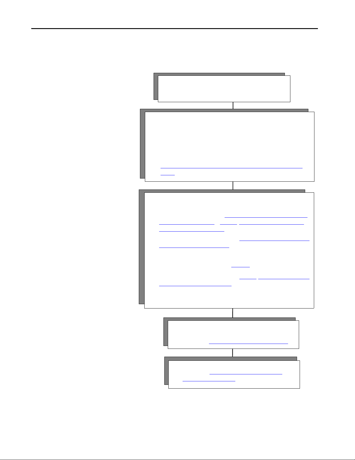
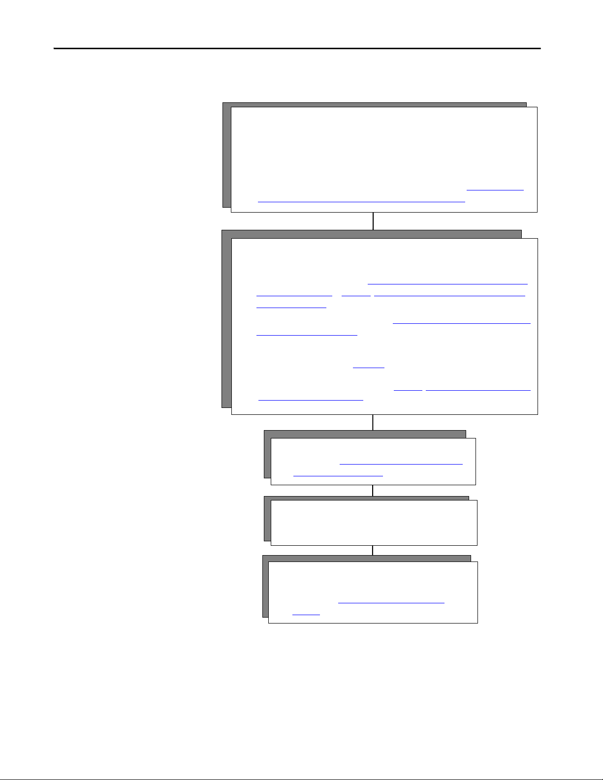
4 - Commission
• Download project.
• Follow steps in Chapter 11, Commission an Axis on page 221
.
Connect Hardware First
5 - Program
• Follow steps in Appendix B, Out of Box Configuration for
PowerFlex Drives on page 305.
3 - Configure the drive module and an axis.
Check drive firmware for the latest revisions and update if needed.
• For Kinetix drives, follow the steps in Chapter 3,Configure Integrated Motion Control
Using Kinetix Drives on page 31 or Chapter 4, Configure Integrated Motion Control
Using Kinetix 5700 Drives on page 59.
• For a PowerFlex 755 drive, follow the steps in Chapter 5, Configure Integrated Motion
Using a PowerFlex 755 Drive on page 99.
If you are using a PowerFlex 755 drive and are unfamiliar with the integrated motion interface
and attributes, see the Integrated Motion on EtherNet/IP appendix in the PowerFlex 750-Series
AC Drives Programming Manual, publication 750-PM001.
• For a PowerFlex 527 drive, follow the steps in Chapter 6, Configure Integrated Motion
Using a PowerFlex 527 Drive on page 129.
2 - Configure the controllers and communication modules.
• Open the Logix Designer application.
• Check software and firmware for the latest revisions and update if needed.
• You must configure the controllers and communication modules for time
synchronization and motion.
• To configure a project and enable time synchronization, follow the steps in
Chapter 2, Create a Project for Integrated Motion on the EtherNet/IP Network on
page 21.
1 - Connect
• Install modules and drives.
• Check software and firmware for the latest revisions.
Configuration and Startup Scenarios
The two ways to get an integrated motion on the EtherNet/IP network
solution to run are to connect the hardware first or configure the software first.
18 Rockwell Automation Publication MOTION-UM003K-EN-P - January 2019
Page 19
Configure Software First
3 - Program
• Follow steps in Appendix B, Out of Box Configuration for
PowerFlex Drives on page 305.
4 - Connect
• Install modules and drives.
• Check software and firmware for the latest revisions.
1 - Configure the controllers and communication modules.
• Open the Logix Designer application.
• Check software and firmware for the latest revisions and update if needed.
• You must configure the controllers and communication modules for time synchronization
and motion.
• To build a project and enable time synchronization, follow the steps in Chapter 2, Create a
Project for Integrated Motion on the EtherNet/IP Network on page 21.
2 - Configure the drive module and configure an axis.
Check drive firmware for the latest revisions and update if needed.
• For Kinetix drives, follow the steps in Chapter 3,Configure Integrated Motion Control Using
Kinetix Drives on page 31 or Chapter 4, Configure Integrated Motion Control Using Kinetix
5700 Drives on page 59.
• For a PowerFlex 755 drive, follow the steps in Chapter 5, Configure Integrated Motion Using
a PowerFlex 755 Drive on page 99.
If you are using a PowerFlex 755 drive and are unfamiliar with the integrated motion interface and
attributes, see the Integrated Motion on EtherNet/IP appendix in the PowerFlex 750-Series AC Drives
Programming Manual, publication 750-PM001.
For a PowerFlex 527 drive, follow the steps in Chapter 6, Configure Integrated Motion Using
a PowerFlex 527 Drive on page 129.
5 - Commission
• Download project.
• Follow steps in Chapter 11, Commission an Axis on
page 221.
Components of a Motion System Chapter 1
Rockwell Automation Publication MOTION-UM003K-EN-P - January 2019 19
Page 20

Chapter 1 Components of a Motion System
Help for Selecting Drives and Motors
Motion Analyzer helps you select the appropriate Allen-Bradley® drives and
motors that are based on your load characteristics and typical motion
application cycles. The software guides you through wizard-like screens to
collect information specific to your application.
After you enter the information for your application, such as, load inertia,
gearbox ratio, feedback device, and brake requirements, the software generates
an easy-to-read list of recommended motors, drives, and other support
equipment.
You can access Motion Analyzer at
https://motionanalyzer.rockwellautomation.com
.
20 Rockwell Automation Publication MOTION-UM003K-EN-P - January 2019
Page 21
Chapter 2
Create a Project for Integrated Motion on the
EtherNet/IP Network
Top ic Pag e
Create a Controller Project 21
Set Time Synchronization 24
Add an Ethernet Communication Module 26
This chapter describes how to configure an integrated motion project in the
Logix Designer application.
Create a Controller Project
IMPORTANT For Motion and Safety applications, you must use a GuardLogix® or Compact
GuardLogix controller.
Follow these instructions to create a project.
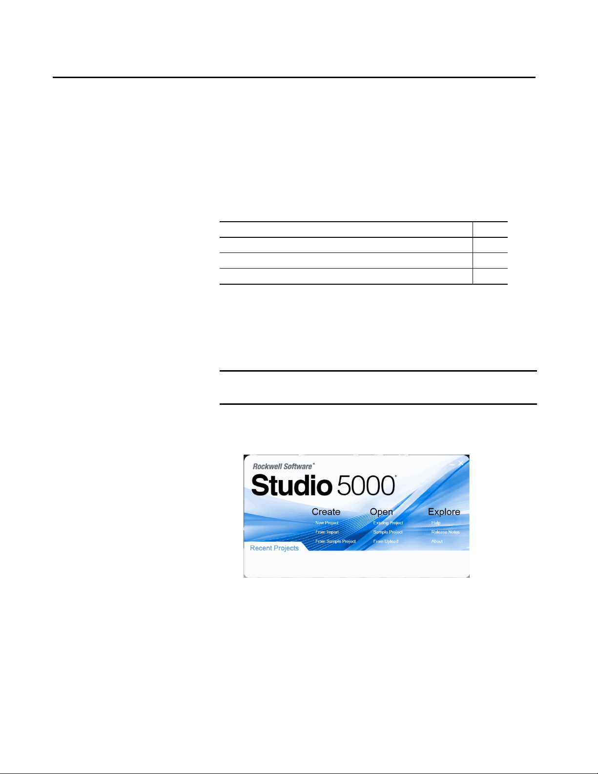
1. On the Studio 5000® dialog box, choose Create New Project.
Rockwell Automation Publication MOTION-UM003K-EN-P - January 2019 21
Page 22

Chapter 2 Create a Project for Integrated Motion on the EtherNet/IP Network
2. Choose a controller, type a name, and click Next.
3. Type a Name for the controller.
4. Assign a location (optional).
5. Click Next.
The Project Configuration dialog box appears.
6. Choose the chassis type.
7. Assign the slot location of the controller.
8. Assign the Security Authority.
9. Type a description (optional).
10. Click Finish.
22 Rockwell Automation Publication MOTION-UM003K-EN-P - January 2019
Page 23
Create a Project for Integrated Motion on the EtherNet/IP Network Chapter 2
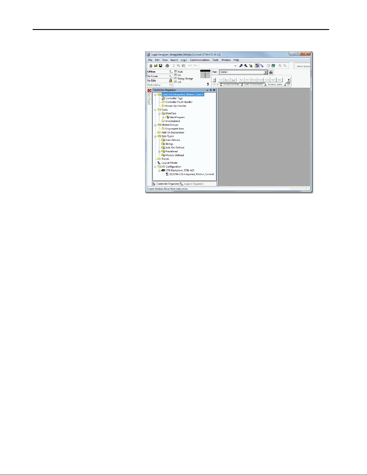
The Logix Designer application opens with new project.
Rockwell Automation Publication MOTION-UM003K-EN-P - January 2019 23
Page 24
Chapter 2 Create a Project for Integrated Motion on the EtherNet/IP Network
EtherNet/IP™
Logix5563
EtherNet/IP™
EtherNet/IP™
SOE INTPUTSOE INTPUT SOE INTPUT SOE INTPUT SOE INTPUT SOE INTPUT
EtherNet/IP™
SOE INTPUTSOE INTPUT SOE INTPUT SOE INTPUT SOE INTPUT SOE INTPUT
Logix5563
EtherNet/IP™
SOE INTPUT SOE INTPUT SOE INTPUT SOE INTPUT
S
P2=1
P2=2
GM
CIP Sync
CIP Sync
CIP Sync
L
7
X
S
O
E
S
O
E
S
O
E
S
O
E
E
N
2
T
S
O
E
S
O
E
S
O
E
S
O
E
S
O
E
S
O
E
E
N
2
T
E
N
2
T
S
O
E
S
O
E
S
O
E
S
O
E
S
O
E
S
O
E
E
N
2
T
E
N
2
T
D
I
O
D
I
O
D
I
O
D
I
O
D
I
O
L
7
X
CIP Sync
S
M
S
S S S
CIP Sync
S
M
S
S
S
S
S
CIP Sync
S
M
S
S
S
S
S
CIP Sync
M
S
CIP Sync
Com
IN2
IN1
Ref
M
NTP
MOD
NET
MOD
NET
MOD
NET
MOD
NET
2
1
1
1
4
I/O
I/O
6
5
10
2
1
2
1
2
1
1
I/O-A
6
510
1
I/O-B
6
510
1
I/O-A61I/O-B
6
510510
UFB
UFB-A UFB-B
UFB-A UFB-B
D+D-D+
D-
D+
D-
MF-A MF-B MF-A MF-B
D+
D-
MBRK
+
-
MOD
NET
2
1
1
I/O-A61I/O-B
6
510510
UFB-A UFB-B
D+
D-
MF-A MF-B
D+
D-
5700
5700
5700
5700
5700
S
S
S
S
M
350
MEM
A=ENABLE
B= REGEN
C=DATA ENTRY
D=FAULT
E=COM ACTIVITY
24VDC
INPUT
BRAKE/
DC BUS
AB D
E
C
ETHERNET
MORTOR FEEDBACK
S
S
CIP Sync
S
Com
IN2
IN1
Ref
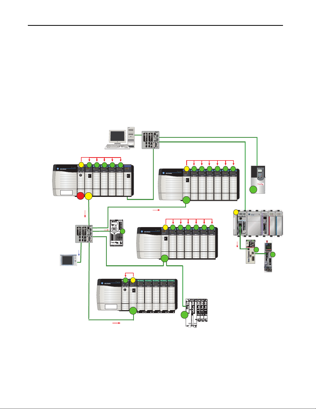
GM = Grandmaster (time source)
M = Master
S = Slave
P1 and P2 = Priorities Priorities are automatically assigned based on their clock quality, which the Best Clock Algorithm determines. In this example, P2=1 is the
best quality so it becomes the Grandmaster. If the P2=1 device loses clock quality for some reason, then P2=2 would become the
Grandmaster for the system.
Supervisory
Stratix® 5700
Stratix 5700
HMI
PowerFlex 527
Kinetix® 350
EtherNet/IP
Kinetix 5500
PowerFlex® 755
Kinetix® 5700
Set Time Synchronization
This technology supports highly distributed applications that require time
stamps, sequence of events records, distributed motion control, and increased
control coordination. All controllers and communication modules must have
time synchronization that is enabled for applications that use integrated
motion on the EtherNet/IP™ network.
Time synchronization in the Logix system is called CIP Sync. CIP Sync
provides a mechanism to synchronize clocks between controllers, I/O, and
other devices that are connected over CIP™ networks and the ControlLogix® or
CompactLogix™ backplane. The device with the best clock becomes the
Grandmaster time source for your system.
Figure 1 - Star Topology with the ControlLogix Controller as the Grandmaster
24 Rockwell Automation Publication MOTION-UM003K-EN-P - January 2019
Page 25
Create a Project for Integrated Motion on the EtherNet/IP Network Chapter 2
The Best Master Clock algorithm determines what device has the best clock.
The device with the best clock becomes the Grandmaster time source for your
system. All controllers and communication modules must have time
synchronization that is enabled to participate in CIP Sync.
See the Integrated Architecture and CIP Sync Configuration Application
Te ch ni qu e , p ub lica ti o n
IA-AT003
, for detailed information.
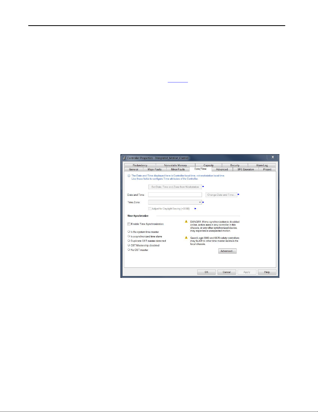
You must enable time synchronization for motion applications. Follow these
instructions to enable time synchronization.
1. In the Controller Organizer, right-click the controller and choose
Properties.
2. Click the Date/Time tab.
3. Check Enable Time Synchronization.
4. Click OK.
Rockwell Automation Publication MOTION-UM003K-EN-P - January 2019 25
Page 26
Chapter 2 Create a Project for Integrated Motion on the EtherNet/IP Network
Add an Ethernet Communication Module
Although ControlLogix 5580 and GuardLogix 5580 controllers can use
Ethernet communication modules, only ControlLogix 5560 and 5570 and
GuardLogix 5560 and 5570 controllers require an Ethernet communication
module for connection to the Ethernet network. See Controller,
Communication, Drive, and Software Options on page 11 for more
information.
Follow these instructions to add an Ethernet communication module to your
project if needed.
IMPORTANT For all communication modules, use the firmware revision that goes with
the firmware revision of your controller. See the release notes for the
firmware of your controller.
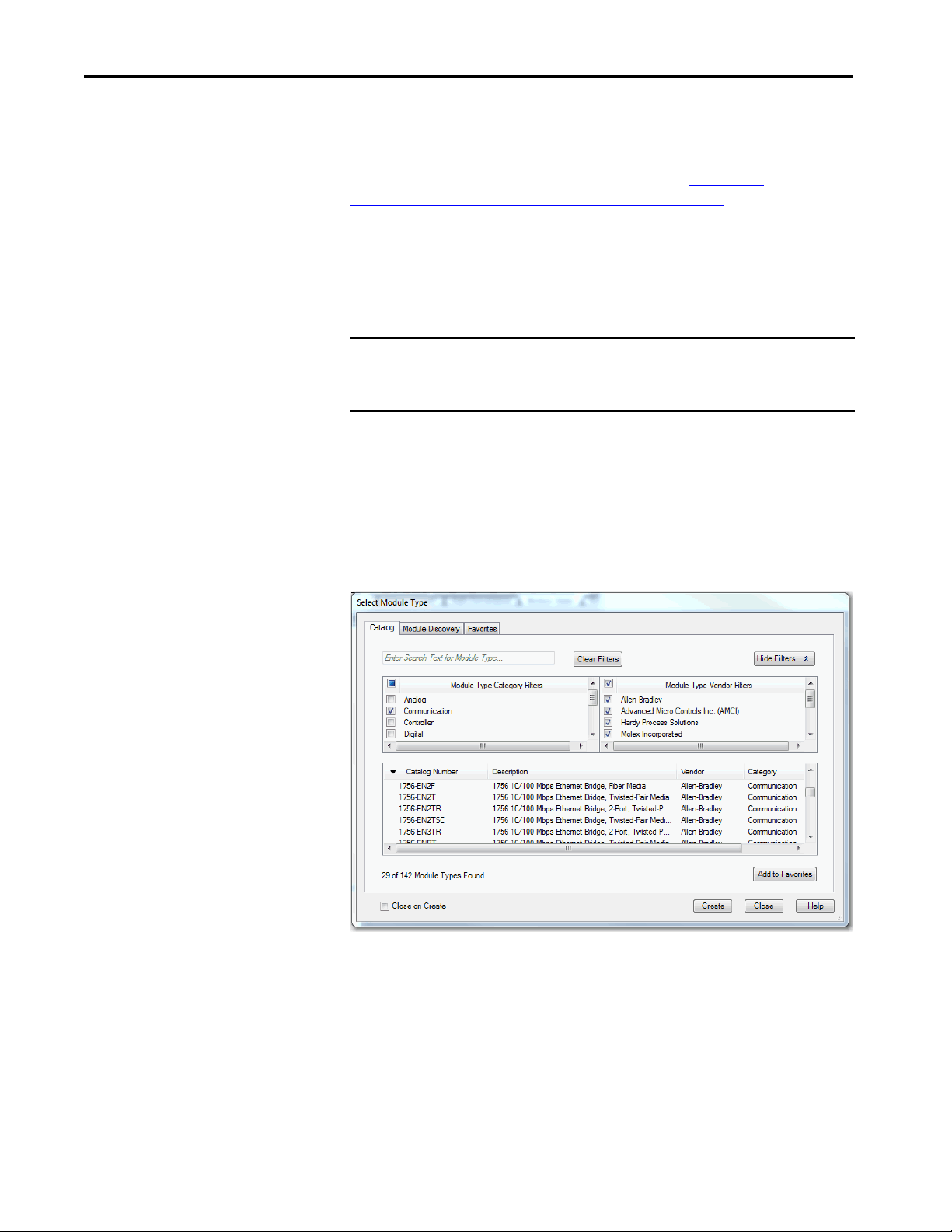
1. To add a module, right-click the backplane and choose New Module.
2. Clear the Module Type Category Filters select all checkbox.
3. Check the Communication checkbox.
On the Select Module Type dialog box, you can filter to the exact type of
module you are looking for, which makes your search faster.
4. Under Communications, select the Ethernet module and click Create.
26 Rockwell Automation Publication MOTION-UM003K-EN-P - January 2019
Page 27
Create a Project for Integrated Motion on the EtherNet/IP Network Chapter 2
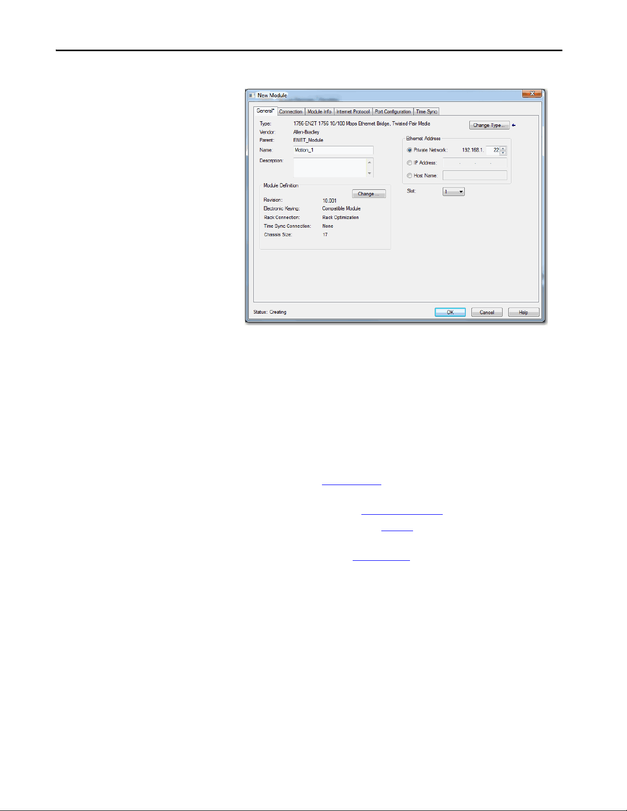
The New Module configuration tabs appear.
5. Type a name for the module.
6. If you want, type a description.
7. Assign the EtherNet/IP address of the Ethernet module.
For information on how to create an Ethernet network and setting IP
addresses for the communication and motion modules, see these
manuals:
– EtherNet/IP Network Configuration User Manual,
publication
ENET-UM001
– PowerFlex® 755 Drive Embedded EtherNet/IP Adapter User
Manual, publication, 750COM-UM001
– Knowledgebase Technote
# 66326
– Converged Plantwide Ethernet (CPwE) Design and Implementation
Guide, publication
ENET-TD001
8. Assign the slot for the module.
9. In the module definition area, click Change.
Rockwell Automation Publication MOTION-UM003K-EN-P - January 2019 27
Page 28
Chapter 2 Create a Project for Integrated Motion on the EtherNet/IP Network
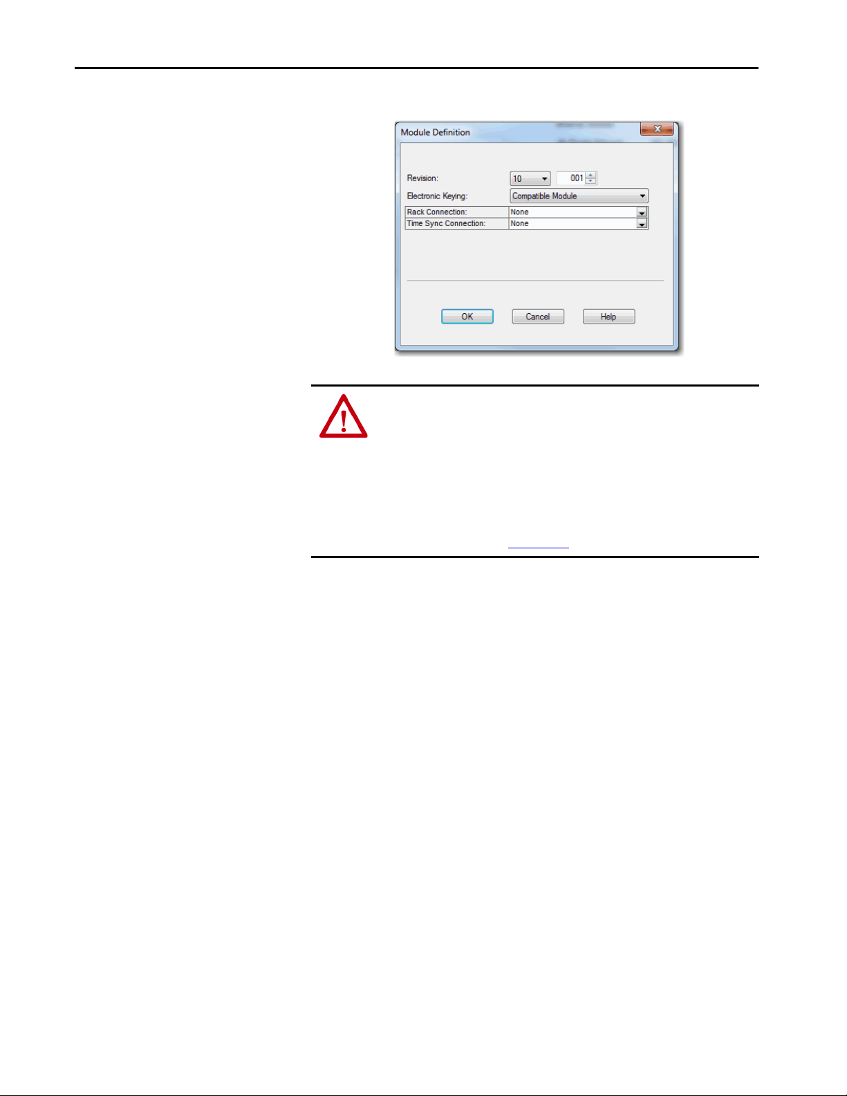
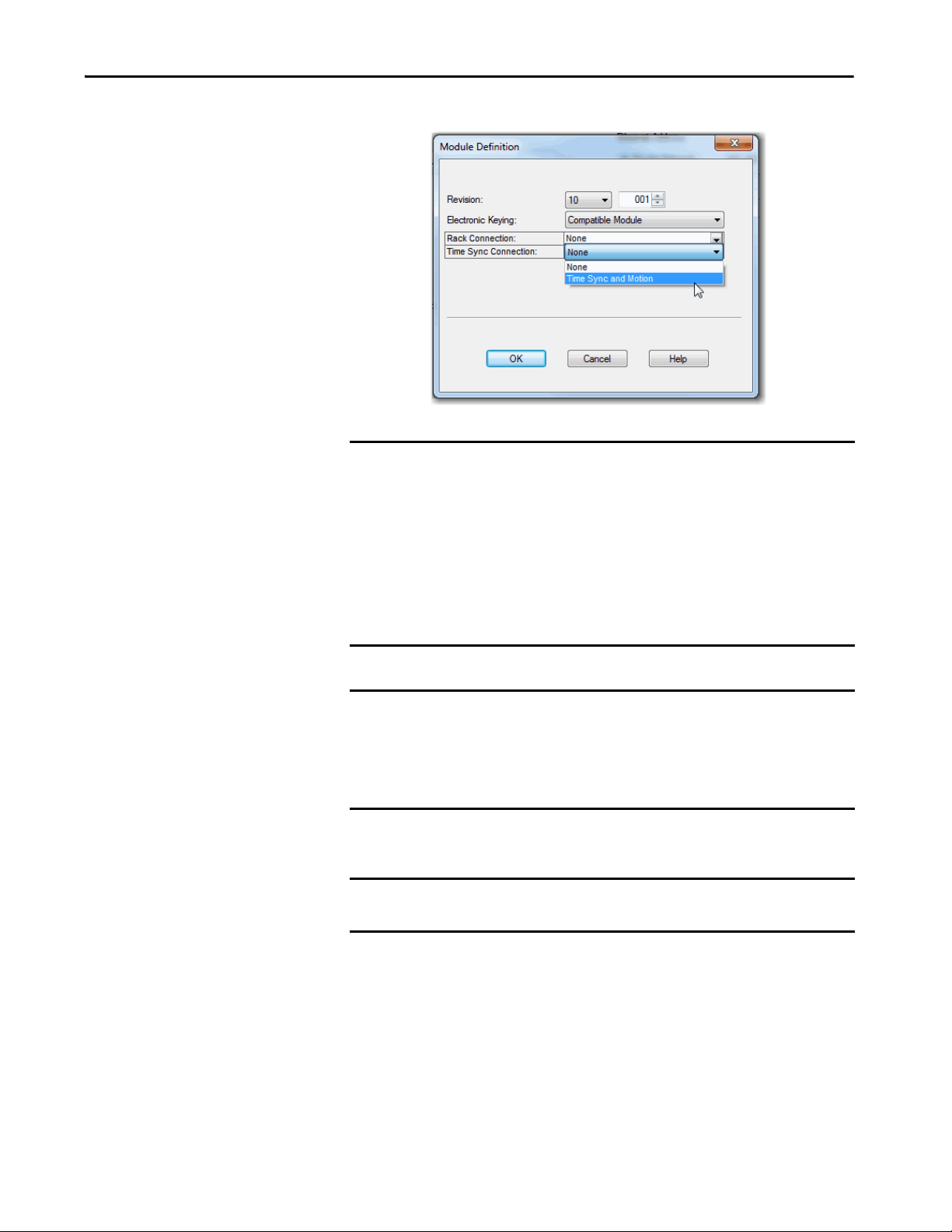
10. Choose an Electronic Keying option.
ATT EN TI ON : The electronic keying feature automatically compares the
expected module, as shown in the configuration tree, to the physical module
before communication begins.
When you are using motion modules, set the electronic keying to either `Exact
Match‘ or `Compatible Keying‘.
Never use `Disable Keying’ with Ethernet communication and motion modules.
For more information about electronic keying, see the ControlLogix Controller
User Manual, publication 1756-UM001
.
28 Rockwell Automation Publication MOTION-UM003K-EN-P - January 2019
Page 29
Create a Project for Integrated Motion on the EtherNet/IP Network Chapter 2
11. Choose Time Sync and Motion.
IMPORTANT For CIP Sync time coordination to work in motion control, you must set the
Time Sync Connection to Time Sync and Motion on all Ethernet
communication modules. The CIP Sync protocol is what enables motion
control on the EtherNet/IP network.
The Time Sync and Motion selection is available only for firmware revision 3
and later. You must be offline to change the Time Sync and Motion selection.
If you are online at a major revision of 1 or 2, you can only change the
revision to a 1 or 2. You must go offline to change the module to revision 3 or
4 and return to revision 1 or 2.
IMPORTANT For CompactLogix 5370 and Compact GuardLogix 5370 controllers, the
embedded dual-port Ethernet is automatically set with Time Sync
Connection= Time Sync and Motion.
To enable Integrated Motion, check the `Enable Time Synchronization’
checkbox on the controller time/date tab.
12. Click OK.
IMPORTANT If you have not enabled time synchronization, you get errors when you try to
associate an axis.
Rockwell Automation Publication MOTION-UM003K-EN-P - January 2019 29
Page 30

Chapter 2 Create a Project for Integrated Motion on the EtherNet/IP Network
Notes:
30 Rockwell Automation Publication MOTION-UM003K-EN-P - January 2019
Page 31

Chapter 3
Configure Integrated Motion Control Using
Kinetix Drives
Top ic Pag e
Add a Kinetix EtherNet/IP Drive 32
Create an Associated Axis 40
Create a Motion Group 42
Configure the Axis Properties 46
Configure the Associated Axis and Control Mode 47
Specify the Motor Data Source 50
Display Motor Model Information 54
Assign Motor Feedback 54
Configure the Load Feedback 55
Configure the Master Feedback 57
This chapter provides procedures on how to configure integrated motion
control by using the Kinetix® 350, Kinetix 5500, and Kinetix 6500 drives. The
basic configuration for an integrated motion solution is to associate a drive
with motor feedback and an axis configuration type.
For the examples in this chapter, the Kinetix 6500 drive is used and the
exceptions for the Kinetix 350, Kinetix 5500 drives noted. See Chapter 4
Configure Integrated Motion Control Using Kinetix 5700 Drives
,
, for Kinetix
5700 configuration information.
See Chapter 8
, Configuration Examples for a Kinetix Drive, for examples of
axis and feedback configurations.
For information about what attributes are replicated in the drive, see the
Integrated Motion on the EtherNet/IP™ network Reference Manual,
publication MOTION-RM003
.
Rockwell Automation Publication MOTION-UM003K-EN-P - January 2019 31
Page 32

Chapter 3 Configure Integrated Motion Control Using Kinetix Drives
Add a Kinetix EtherNet/IP Drive
See Tab le 2 o n p ag e 11 to determine the minimum version of the Studio 5000
Logix Designer® application that is required for your drive.
IMPORTANT • For complete information on how to configure Kinetix 5500 drives,
including drives with integrated safety connections, see the Kinetix 5500
Servo Drives User Manual, publication 2198-UM001
.
• For complete information about how to configure the Kinetix 350 drives,
see the Kinetix 350 Single-axis EtherNet/I/P Servo Drive User Manual,
publication 2097-UM002
.
• For complete information about to configure the Kinetix 6500 drives, see
the Kinetix 6200 and Kinetix 6500 Modular Multi-axis Servo Drives User
Manual, publication 2094-UM002
.
Follow these instructions to add a Kinetix drive your project.
1. Right-click the Ethernet network (node) and choose New Module.
2. To filter the selections, check the Motion checkbox.
3. Choose the Kinetix 350, Kinetix 5500, or Kinetix 6500 drive.
4. Click Create.
32 Rockwell Automation Publication MOTION-UM003K-EN-P - January 2019
Page 33
Configure Integrated Motion Control Using Kinetix Drives Chapter 3
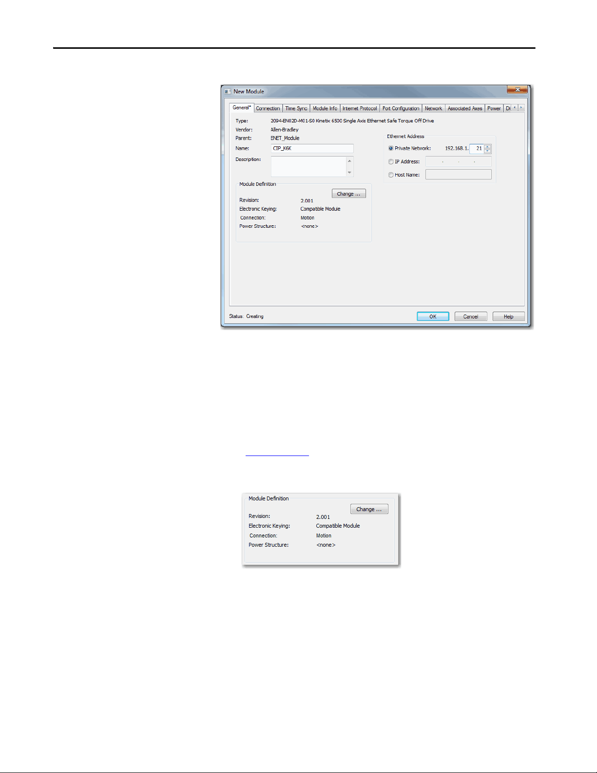
5. Type a Name for the module.
6. Type a description, if desired.
7. Assign an EtherNet/IP address.
You can establish the Node address of the drive by entering a private IP
address via a thumbwheel switch on the drive for Private Network
segments. Use the format 192.168.1.xxx, where the last octet, xxx, is the
switch setting.
See the EtherNet/IP Network Configuration User Manual, publication
ENET-UM001
, for information on setting IP addresses and other
Ethernet network considerations.
8. Under Module Definition, click Change.
Rockwell Automation Publication MOTION-UM003K-EN-P - January 2019 33
Page 34

Chapter 3 Configure Integrated Motion Control Using Kinetix Drives
9. Choose an Electronic Keying option.
The Module Definition dialog box appears.
ATTENTION: The electronic keying feature automatically compares
the expected module, as shown in the configuration tree, to the
physical module before communication begins.
When you are using motion modules, set the electronic keying to either
`Exact Match‘ or `Compatible Keying‘.
Never use `Disable Keying’ with motion modules.
For more information about electronic keying, see the Electronic Keying
in Logix 5000™ Control Systems Application Technique, publication
LOG IX-AT 001
.
34 Rockwell Automation Publication MOTION-UM003K-EN-P - January 2019
Page 35

Configure Integrated Motion Control Using Kinetix Drives Chapter 3
10. Assign the appropriate Power Structure.
When you select a Kinetix 6500 drive catalog number, you are specifying
only a Control Module. To specify the drive, you must assign a power
structure. Some of the drives do not require a power structure.
TIP You can locate the power-structure reference numbers by doing the
following:
• Check the hardware
• See the device documentation
• Reviewing the purchase order or the bill of materials.
You assign the power structure for the Kinetix 6500 drive only.
Kinetix 350 and Kinetix 5500 drives auto-populate the only power
structure available.
11. Check the checkbox if you want to verify the power rating on
connection.
12. Click OK.
When you change the Module Definition, related parameters also
change. By changing the major revision or power structure, the identity
of the drive changes. If your drive is associated to an axis, these changes
disassociate the axis.
Rockwell Automation Publication MOTION-UM003K-EN-P - January 2019 35
Page 36

Chapter 3 Configure Integrated Motion Control Using Kinetix Drives
Configure the Safety Category - Kinetix 5500 Drives
The Safety tab provides you with information about the connection between
the owner and the 2198-Hxxx-ERS2 servo drive. The information comes from
the controller.
The connection between the owner and the 2198-Hxxx-ERS2 servo drive is
based on the following:
• Servo drive catalog number must be 2198-Hxxx-ERS2 (integrated)
• Servo drive safety network number
•GuardLogix® slot number
• GuardLogix safety network number
• Path from the GuardLogix controller to the 2198-Hxxx-ERS2 drive
• Configuration signature
The connection between the GuardLogix controller and the 2198-Hxxx-ERS2
drive is lost if any differences are detected. The yellow yield icon also appears in
the controller project tree after you download the program.
For complete information on how to configure a drive with integrated safety
connections, see the Kinetix 5500 Servo Drives User Manual,
publication 2198-UM001
.
36 Rockwell Automation Publication MOTION-UM003K-EN-P - January 2019
Page 37

Configure Integrated Motion Control Using Kinetix Drives Chapter 3
Configure the Power Options
1. Click the Power tab.
IMPORTANT Single-phase operation is possible only when Module Properties >
Power tab > Bus Configuration is configured as Standalone and Voltage
is configured as 200…240V AC.
IMPORTANT The Logix Designer application enforces shared-bus configuration rules
for Kinetix 5500 drives, except for shared AC configurations.
2. From the pull-down menus, choose the power options appropriate for
your actual hardware configuration.
ATTENTION: To avoid damage to equipment, make sure the AC input
voltage that is configured in the Logix Designer application matches
the actual hardware being configured.
Attribute Menu Description
Vol tag e
AC Input Phasing
Bus Configuration
(1)
400-480 VAC 324…528 AC rms input voltage
200-240 VAC 195…264 AC rms input voltage
• Three Phase
• Single Phase
Standalone
Shared AC/DC
Shared DC
Input power phasing. Kinetix 5500 drives with
single-phase operation is limited to 2198-H003ERSx, 2198-H008-ERSx, and 2198-H015-ERSx.
Applies to single-axis drives and drives with
Shared AC input configurations.
Applies to converter drives with Shared AC/DC
and Shared AC/DC Hybrid input configurations.
Applies to inverter drives with Shared DC input
(common-bus) configurations.
Rockwell Automation Publication MOTION-UM003K-EN-P - January 2019 37
Page 38

Chapter 3 Configure Integrated Motion Control Using Kinetix Drives
Attribute Menu Description
Standalone Applies to standalone bus configurations.
Bus-sharing Group
•Group1
•Group2
Applies to any bus-sharing configuration.
(2)
•Group3…
Disables the internal shunt resistor and external
shunt option.
Shunt Regulato r Action
Disabled
Shunt Regulator Enables the internal and external shunt options.
Internal
Shunt Regulator Resistor Type
External
External Shunt
(3)
•None
• 2097-R6
• 2097-R7
(1) Bus Configuration selection is not applicable to all EtherNet/IP drives.
(2) All drives physically connected to the same shared-bus connection system must be part of the same bus-sharing
group in the Logix Designer application.
(3) See the Kinetix Servo Drives Specifications Technical Data, publication KNX-TD003
Bulletin 2097 external shunt resistors.
Enables the internal shunt (external shunt option
is disabled).
Enables the external shunt (internal shunt
option is disabled).
Selects external shunt option. Only the shunt
model that is intended for the drive model is
shown.
, for more information on the
3. Click OK.
You can change the overload and voltage limits when you are offline. You
cannot change settings while online but the values are displayed.
Figure 2 - Kinetix 5500 Offline Display of the Advanced Limits Dialog Box
(1)
See publication 2198-UM001, Kinetix 5500 Servo Drives, for more
information.
(1) Not applicable to the Kinetix 350 drive.
38 Rockwell Automation Publication MOTION-UM003K-EN-P - January 2019
Page 39

Configure Integrated Motion Control Using Kinetix Drives Chapter 3
Configure Digital Inputs
Use the Digital Input tab to enter digital input values for the drive module.
These offline displays are the default values for the Kinetix 6500 and
PowerFlex® 755 Ethernet drives. The appearance of the Digital Input tabs of
the PowerFlex 755 drives can vary dependent upon the peripheral device
configuration. The Kinetix 350 drive does not have a Digital Input tab.
Figure 3 - Digital Input Tab for the Kinetix 5500 Drive
Table 7 - Module Properties: Kinetix 5500 Digital Input Tab Descriptions
Parameter Description
Digital Input 1
Digital Input 2
Choose one of these values for Digital Input 1 and 2:
• Unassigned
•Enable
•Home
• Registration 1
• Registration 2
• Positive Overtravel
• Negative Overtravel
• Home and Registration 1
Figure 4 - Digital Input Tab for the Kinetix 6500 Drive
Rockwell Automation Publication MOTION-UM003K-EN-P - January 2019 39
Page 40

Chapter 3 Configure Integrated Motion Control Using Kinetix Drives
Table 8 - Module Properties: Kinetix 6500 Digital Input Tab Descriptions
Parameter Description
Digital Input 1
Digital Input 2
Digital Input 3
Digital Input 4
Choose one of these values for Digital Input 1, 2, 3, and 4:
• Unassigned
•Enable
• Home
• Registration 1
• Registration 2
• Positive Overtravel
• Negative Overtravel
• Regeneration OK
Create an Associated Axis
There are two approaches that you can take to create and configure an axis. You
can create an axis first and then add the axis to your motion group or you can
create your motion group and then add an axis.
The procedure that is outlined in this section takes the approach to create your
axis first, add it to your motion group, and then configure the axis.
Create an Axis for a Kinetix Drive
Follow these steps to create an axis.
1. To open the Module Properties dialog box, double-click the drive in the
Controller Organizer.
2. Click the Associated Axes tab.
3. Click New Axis.
40 Rockwell Automation Publication MOTION-UM003K-EN-P - January 2019
Page 41

Configure Integrated Motion Control Using Kinetix Drives Chapter 3
The New Tag dialog box appears.
Notice that the fields in the next steps are automatically entered for the
AXIS_CIP_DRIVE data type.
4. Type a Tag name.
5. Type a Description, if desired.
6. Choose the Tag Type.
7. Choose the Data Type AXIS_CIP_DRIVE.
8. Choose the Scope.
9. Choose the External Access.
For more information about External Data Access Control and
Constants, see the Logix5000 Controllers I/O and Tag Data
Programming Guide, publication 1756-PM004
.
10. Click Create.
Establish Feedback Port Assignments
Kinetix 350 and Kinetix 5500 drives have one Motor Feedback Port, which is
automatically assigned.
The Kinetix 6500 drive has two feedback ports. Port 1 is reserved for Motor
Feedback on the primary axis (Axis_1). Port 2 can be used either as Load
Feedback for the primary axis or as a Master Feedback for a secondary feedback
only axis (Axis_2).
To establish feedback port assignments for Kinetix 6500 drives, follow these
steps.
Rockwell Automation Publication MOTION-UM003K-EN-P - January 2019 41
Page 42

Chapter 3 Configure Integrated Motion Control Using Kinetix Drives
1. To access Module Properties, double-click the Kinetix 6500 drive in the
2. Click the Associated Axes tab.
3. From the Load Feedback Device pull-down menu, choose AUX
Controller Organizer.
Notice that the motor feedback is already configured by default.
The AUX Feedback Port (Port 2) of the drive can be optionally used for
load feedback of the primary axis (Axis 1) to support Load or Dual
Feedback Configuration.
Feedback Port.
Create a Motion Group
42 Rockwell Automation Publication MOTION-UM003K-EN-P - January 2019
All axes must be added to the Motion Group in your project. If you do not
group the axes, they remain ungrouped and unavailable for use. You can only
have one Motion Group per Logix controller.
To determine how many axes are supported by your controller system, see
Ta b l e 3
To create a motion group, follow these instructions.
on page 12, Supported Axes by Controller Type.
1. In the Controller Organizer, right-click Motion Groups and choose
New Motion Group.
The New Tag dialog box appears.
Page 43
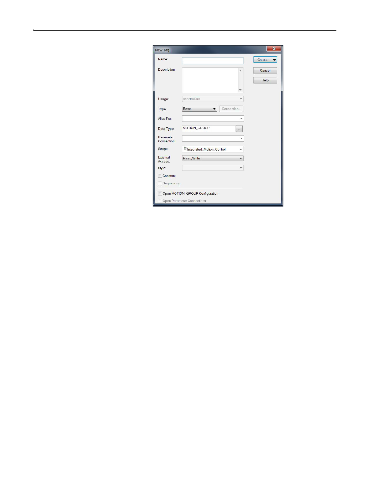
Configure Integrated Motion Control Using Kinetix Drives Chapter 3
2. Type a Tag name.
3. Type a description, if desired.
4. Choose the Tag Type.
5. Choose the Scope.
6. Choose the External Access.
7. Click Create.
Your new motion group appears in the Controller Organizer under the
Motion Groups folder.
8. Right-click the new motion group and choose Properties.
The Motion Group Properties dialog box appears.
Rockwell Automation Publication MOTION-UM003K-EN-P - January 2019 43
Page 44

Chapter 3 Configure Integrated Motion Control Using Kinetix Drives
9. Click the Axis Assignment tab and move your axes (created earlier) from
Unassigned to Assigned.
Set the Base Update Period
The Base Update Period is basically the RPI rate for Ethernet communication
between the controller and the motion module, a Unicast connection.
There are two alternate update periods that you can configure when using the
Axis Scheduling function. See Axis Scheduling on page 145
The Base Update Period determines how often the Motion Task runs. When
the Motion Task runs, it interrupts most other tasks regardless of their priority.
The Motion Task is the part of the controller that takes care of position and
velocity information for the axes.
for details.
44 Rockwell Automation Publication MOTION-UM003K-EN-P - January 2019
Page 45

Configure Integrated Motion Control Using Kinetix Drives Chapter 3
Motion Task
Scans of Your Code, System
Overhead, and so on
0 ms 10 ms
20 ms 30 ms 40 ms
In this example, the Base Update Period = 10 ms. Every 10 ms the controller stops scanning your code and whatever else it is doing and
runs the motion planner.
To set the Base Update Period, follow these steps.
1. Click the Attribute tab in the Motion Group Properties dialog box.
2. Set the Base Update Period to 2.0…32.0 ms.
TIP Check the Last Scan time values. Typically, the value is less than
50% of the Base Update Period.
For the Kinetix 6500 drive, the minimum Base Update Rate is 1 ms.
Figure 5 - Base Update Period Example
The Base Update Period is a trade-off between updating positions of your axes
and scanning your code. In general, you do not want the Motion Task to take
more than 50% of the overall Logix controller time on average. The more axes
that you add to the Motion Group, the more time it takes to run the Motion
Ta s k .
Rockwell Automation Publication MOTION-UM003K-EN-P - January 2019 45
Page 46

Chapter 3 Configure Integrated Motion Control Using Kinetix Drives
For the ControlLogix® 5570 controller, the incremental impact on the Motion
Task is roughly at 6…8 drives/ms. Actual impact can vary depending on axis
configuration.
For detailed information on the Axis Scheduling function, Axis Assignment
tab, and Alternate Update Period Scheduling, see Axis Scheduling on
page 145.
Integrated Architecture Builder
To help you determine motion system performance, use the motion
performance calculator in the Integrated Architecture Builder (IAB).
The IAB is a graphical software tool for configuring Logix-based automation
systems. It helps you select hardware and generate bills of material for
applications that include controllers, I/O, networks, PowerFlex drives, OnMachine™ cabling and wiring, motion control, and other devices.
You can find the software at
http://www.rockwellautomation.com/en/e-tools/configuration.html
Configure the Axis Properties
After you add the drive to your project and create the axes, use the Axis
Properties dialog boxes to configure the drive. Notice that the dialog boxes
change based on your configuration choices, for example, feedback
configuration.
Ta b l e 9
Table 9 - Category Dialog Boxes to Configure Drives
lists the basic tasks necessary configure a drive.
Category Dialog Box Perform These Tasks Page
General • Assign the axis configuration.
• Choose the feedback configuration.
• Choose the application type, if applicable.
• Choose the loop response (low, medium, or high), if applicable.
• If you have not already done so, you can create and associate an axis to a
new Motion Group and associate a drive module to the axis.
Motor • Specify a motor with the Data Source = Nameplate data sheet.
• Specify a motor with the Data Source = Catalog Number.
• Select a motor with the Data Source = Motor NV.
Motor Feedback • Select the Motor Feedback Type. 54
Load Feedback • Select the Load Feedback Type, if applicable. 55
Scaling • Configure feedback by choosing the load t ype, by entering the scaling units,
and by choosing the Travel mode.
• Enter the Input Transmission and Actuator ratio, if applicable.
47
51
222
The parameters that you configure on the General category dialog box result in
the presentation of attributes and parameters that are available for the
combination of your selections.
46 Rockwell Automation Publication MOTION-UM003K-EN-P - January 2019
Page 47

Configure Integrated Motion Control Using Kinetix Drives Chapter 3
IMPORTANT All AXIS_CIP_DRIVE Axis Properties dialog boxes are dynamic. Optional
attributes and dialog boxes that are related to each integrated motion
axis you create come and go based on what combination of axis
characteristics you define.
See the Integrated Motion Reference Manual, publication MOTION-RM003,
for complete information on Axis Attributes and how to apply Control Modes.
IMPORTANT Be sure to associate the drive and axis before configuring the axis
because the drive determines what optional attributes are supported for
the axis.
If you have already created an axis and associated it with a drive, the Associated
Module and Axis are shown on the General category of the Axis Properties
dialog box. Otherwise, you can select them here.
Figure 6 - General Category Dialog Box
Configure the Associated Axis and Control Mode
Rockwell Automation Publication MOTION-UM003K-EN-P - January 2019 47
The Axis Number field corresponds to the axes listed on the Associated Axes
tab of the Module Properties dialog box. Any feedback port assignments that
you made on the Associated Axes tab are also mapped to the drive when you
associate an axis and a drive.
Now that the axis is associated to the drive module, meaningful values are
available for other axis properties.
For more information on Control Modes, see the Integrated Motion Reference
Manual, publication MOTION-RM003
1. In the Controller Organizer, double-click the Axis that you want to
configure.
.
Page 48

Chapter 3 Configure Integrated Motion Control Using Kinetix Drives
2. Choose an Axis Configuration type. For this example, choose Position
The Axis Properties General dialog box appears.
Loop.
TIP The associated drive determines what Axis and Feedback
Configuration choices are presented.
Ta b l e 1 0
Table 10 - Compare the Axis Configuration Types for the Drives
Axis Type Kinetix 350 Kinetix 5500 Kinetix 6500
Position Loop (P) Yes Yes Yes
Velocity Loop (V) Yes Yes Yes
Torque Loop (T) Yes Yes Yes
Feedback Only (N) No Yes Yes
Frequenc y Control (F) No Yes No
compares the axis configuration types for the drives.
3. In the Feedback Configuration pull-down menu, choose Motor
Feedback.
TIP The Kinetix 350 and Kinetix 5500 drives support only Motor
Feedback.
48 Rockwell Automation Publication MOTION-UM003K-EN-P - January 2019
Page 49

Configure Integrated Motion Control Using Kinetix Drives Chapter 3
Ta b l e 1 1 compares the feedback configuration types for the Kinetix
drives.
P
Table 11 - Compare the Feedback Configuration Types for the Drives
Feedback Type Axis Type Kinetix 350 Kinetix 5500 Kinetix 6500
Motor Feedback Position Loop (P),
Velocity Loop (V),
Tor que Lo op ( T)
Load Feedback Position Loop (P),
Velocity Loop (V),
Tor que Lo op ( T)
Dual Feedback Position Loop (P) No No Yes
Dual Integrator Position Loop (P) No No No
Master Feedback Feedback Only (N) No Yes Yes
No Feedback Velocity Loop (V),
Frequenc y Control (F)
Yes Yes Ye s
No No Yes
No Yes No
4. Choose an Application Type, if applicable.
TIP Application Type defines the servo loop configuration
automatically. These combinations determine how the
calculations are made that can minimize the need for you to
perform an Autotune or a Manual Tune.
The Application Type determines the type of motion control
application. This attribute is used to set the Gain Tuning Configuration
Bits. Ta b l e 1 2
Table 12 - Customize Gains to Tune
Application Type Kpi Kvi ihold Kvff Kaff torqLPF
(1)
Custom
Basic (V20 and later) No No No Yes No Yes
Basic (V19 and earlier) No No No No No -
Tracking No Yes No Yes Yes Yes
Po i nt - to - Po in t Ye s N o Ye s No No Ye s
Constant Speed No Yes No Yes No Yes
(1) If you set the type to Custom, you can control the individual gain calculations by changing the bit settings in the Gain Tuning
Configuration Bits Attribute.
illustrates the gains established based on application type.
-----
Rockwell Automation Publication MOTION-UM003K-EN-P - January 2019 49
Page 50

Chapter 3 Configure Integrated Motion Control Using Kinetix Drives
5. Choose a Loop Response, if applicable.
TIP Loop Response settings also impact the calculations that are made that
can minimize the need for you to perform an Autotune or a Manual Tune.
The loop response impacts the spacing between the position and
velocity loops and the proportional and integral gains. This response
impacts how aggressively a given profile is tracked.
Specify the Motor Data Source
The Motor Data Source is where you tell the axis where the motor
configuration values are originating. You can select a motor by catalog number
from the Motion Database. You can enter motor data from a nameplate or data
sheet, or use the motor data that is contained in the drive or motor nonvolatile
memory.
On the Motor dialog box you specify what motor you want to use and where
the data is coming from:
• Specify a motor with the Data Source = Nameplate data sheet.
• Specify a motor with the Data Source = Catalog Number.
• Select a motor with the Data Source = Motor NV.
50 Rockwell Automation Publication MOTION-UM003K-EN-P - January 2019
Page 51

Configure Integrated Motion Control Using Kinetix Drives Chapter 3
The asterisk nex t
to a categor y
means that you
have not applied
changes.
To reduce the size of the
list, use these filters.
Choose the Catalog Number as the Motor Data Source
To choose a motor from the Motion Database, follow these steps.
1. If the Axis Properties dialog box is not open, double-click the axis.
2. Go to the Motor dialog box of Axis Properties.
3. From the Data Source pull-down menu, choose Catalog Number.
4. Click Change Catalog.
5. Select a motor.
Rockwell Automation Publication MOTION-UM003K-EN-P - January 2019 51
Page 52

Chapter 3 Configure Integrated Motion Control Using Kinetix Drives
6. Click Apply.
The Motor category dialog box is now populated with all information
that is related to the motor you selected from the Motion Database.
TIP When you use a motor catalog number as the data source, default
values are automatically set based on the Application Type and Loop
Response settings from the General dialog box.
Choose Nameplate as the Motor Data Source
The Nameplate option requires you to enter the motor specification
information from the motor nameplate and the motor data sheet.
1. On the Motor dialog box of Axis Properties, from the Data Source pulldown menu, choose Nameplate data sheet.
2. Choose a motor type.
Ta b l e 1 3
52 Rockwell Automation Publication MOTION-UM003K-EN-P - January 2019
shows the motor types and drives that are compatible.
Page 53

Configure Integrated Motion Control Using Kinetix Drives Chapter 3
Table 13 - Compatible Motor Types
Motor Type Kinetix 350 Kinetix 5500 Kinetix 6500
Surface Mount Permanent
Magnet
Linear Permanent Magnet
Rotary Induction No Yes No
Interior Permanent Magnet No No No
Ye s Yes Ye s
No
Ye s Ye s
Notice that the motor information fields are initialized to defaults.
3. Enter the parameter information from the motor Nameplate data sheet
and click Apply.
Choose Motor NV as the Motor Data Source
When you choose Motor NV as the data source, the motor attributes are
derived from nonvolatile memory of a motor-mounted smart feedback device
that is equipped with a serial interface. Only a minimal set of motor and motor
feedback (Feedback 1) attributes are required to configure the drive.
1. From the Motor dialog box of Axis Properties, choose Motor NV.
2. Choose the Motor Units that are associated with the motor, either Rev
for rotary motor or Meters for linear motor.
No other motor information is needed.
3. Click Apply.
Rockwell Automation Publication MOTION-UM003K-EN-P - January 2019 53
Page 54

Chapter 3 Configure Integrated Motion Control Using Kinetix Drives
The aster isk next
to a category
means that you
have not applied
changes.
Display Motor Model Information
The Motor Model category displays more information that is based on the
motor type you select.
• If the motor data source is Catalog Number, this information is
populated automatically.
• If the motor data source is Nameplate data sheet, this information must
be entered manually, or by running the optional Motor Analyzer.
• If the motor data source is Motor NV, this dialog box is blank.
Assign Motor Feedback
What appears on the Motor Feedback dialog box is dependent on what you
select on the General dialog box for Feedback Configuration.
The Motor Feedback dialog box represents the information for the feedback
device that is directly coupled to the motor. This dialog box is available if the
feedback configuration that is specified on the General dialog box is anything
other than Master Feedback.
If the motor that you select has Catalog Number as the data source, all
information on this dialog box with be entered automatically. Otherwise you
have to enter the information yourself.
Attributes that are associated with the Motor Feedback dialog box are
designated as Feedback 1.
54 Rockwell Automation Publication MOTION-UM003K-EN-P - January 2019
Page 55

Configure Integrated Motion Control Using Kinetix Drives Chapter 3
For you r convenien ce, you can use this link
to the Module Properties dialog box for the
associated drive.
If a permanent magnet motor is selected from the Motion Database, the
Commutation Alignment is set to Controller Offset. However, if a permanent
magnet motor is specified from Nameplate data sheet, you must specify the
Commutation Alignment method. The default is set to Not Aligned.
Table 14 - Commutation Alignment Settings
Type Des cript ion
Not Aligned Not Aligned indicates that the motor is not aligned, and that the
Commutation Offset value is not valid. If the Commutation Offset is not
valid, the drive cannot use it to determine the commutation angle. Any
attempt to enable the drive with an invalid commutation angle results in
a Start Inhibit condition.
Controller Offset Controller Offset applies the Commutation Offset value from the
controller to determine the electrical angle of the motor.
Motor Offset The drive derives the commutation that is offset directly from the motor.
Self-Sense The drive automatically measures the commutation that is offset when it
transitions to the Starting state for the first time after a power cycle. This
alignment type generally applies to a PM motor equipped with a simple
incremental-feedback device.
Configure the Load Feedback
In most cases, the Commutation Alignment is set to Controller Offset and the
Commutation test is run during commissioning to determine the
Commutation Offset and Polarity.
See the Integrated Motion Reference Manual, publication MOTION-RM003
for more information on axis attributes.
The Load Feedback category contains the information from the feedback
device that is directly coupled to the load-side of a mechanical transmission or
actuator.
,
Rockwell Automation Publication MOTION-UM003K-EN-P - January 2019 55
Page 56

Chapter 3 Configure Integrated Motion Control Using Kinetix Drives
The Load Feedback category is available if the Feedback Configuration that is
specified on the General dialog box is Load or Dual.
Attributes that are associated with the Load Feedback category are designated
Feedback 2.
Unlike the Motor Feedback category, you must explicitly enter load feedbackdevice information on the Load Feedback category, including the Feedback
Type. This entry is required because the Load Feedback device is not built into
the motor.
Default values are displayed based on the Feedback Type selected.
56 Rockwell Automation Publication MOTION-UM003K-EN-P - January 2019
Page 57

Configure Integrated Motion Control Using Kinetix Drives Chapter 3
Configure the Master Feedback
The Master Feedback category is available if the Feedback Configuration that
is specified in the General category is Master Feedback. The attributes that are
associated with the Master Feedback category are associated with Feedback 1.
Again, like the Load Feedback category, you must enter all information.
To verify that motor and feedback device are functioning properly, download
to the controller, and continue on to Hookup Tests on page 226
.
Configure Feedback Only Axis Properties
To create your external encoder module and configure feedback-only axis
properties if you are using the 842E-CM integrated motion encoder on the
EtherNet/IP network, see Example 7: 842E-CM Integrated Motion Encoder
with Master Feedback on page 183.
Rockwell Automation Publication MOTION-UM003K-EN-P - January 2019 57
Page 58

Chapter 3 Configure Integrated Motion Control Using Kinetix Drives
58 Rockwell Automation Publication MOTION-UM003K-EN-P - January 2019
Page 59

Chapter 4
Configure Integrated Motion Control Using
Kinetix 5700 Drives
Top ic Pag e
Add a Kinetix 5700 EtherNet/IP Drive 60
Create a Motion Group 83
Configure the Axis Properties 86
Configure the Associated Axis and Control Mode 88
Specify the Motor Data Source 91
Display Motor Model Information 95
Assign Motor Feedback 95
Configure the Load Feedback 97
Configure the Master Feedback 98
This chapter provides procedures on how to configure integrated motion
control by using the Kinetix® 5700 drive. The basic configuration for an
integrated motion solution is to associate a drive with motor feedback and an
axis configuration type.
For information about what attributes are replicated in the drive, see the
Integrated Motion on the EtherNet/IP™ network Reference Manual,
publication MOTION-RM003
See Chapter 8
configuration information.
For complete information on how to configure Kinetix 5700 drives, including
drives with integrated safety connections, see the Kinetix 5700 servo drives
User Manual, publication 2198-UM002
, Configuration Examples for a Kinetix Drive, for Kinetix 5700
.
.
Rockwell Automation Publication MOTION-UM003K-EN-P - January 2019 59
Page 60

Chapter 4 Configure Integrated Motion Control Using Kinetix 5700 Drives
Add a Kinetix 5700 EtherNet/IP Drive
See Integrated Motion on EtherNet/IP Drive Software Options on page 13 to
determine the minimum required version of the Studio 5000 Logix Designer®
application for your drive.
Configure the DC-bus Power Supply and Associate an Axis
Follow these steps to configure the DC-bus power supply.
1. Below the controller you created, right-click Ethernet and choose New
Module.
The Select Module Type dialog box appears.
2. By using the filters, check Motion and Allen-Bradley, and select your
2198-Pxxx DC-bus power supply as appropriate for your actual
hardware configuration.
This example uses a 2198-P208 DC-bus power supply.
3. Click Create.
60 Rockwell Automation Publication MOTION-UM003K-EN-P - January 2019
Page 61

Configure Integrated Motion Control Using Kinetix 5700 Drives Chapter 4
The New Module dialog box appears.
4. Configure the new drive.
a. Type the drive Name.
b. Select a EtherNet/IP address option.
In this example, the Private Network address is selected.
c. Enter the address of your 2198-P208 DC-bus power supply.
In this example, the last octet of the address is 1.
5. Click the Power category.
IMPORTANT The Studio 5000 Logix Designer application enforces shared-bus
configuration rules for Kinetix 5700 drives.
Rockwell Automation Publication MOTION-UM003K-EN-P - January 2019 61
Page 62

Chapter 4 Configure Integrated Motion Control Using Kinetix 5700 Drives
6. From the pull-down menus, choose the power options appropriate for
your actual hardware configuration.
Attribute Menu Description
Bus Configuration Shared AC/DC
Bus-sharing Group
Bus Regulator Action
Shunt Regulator Resistor Type
External Shunt
(1) Shared AC/DC bus configuration is the default selection for DC-bus power supplies.
(2) For more information on bus-sharing groups, refer to Kinetix 5700 servo drives User Manual, publication 2198-UM002
(3) See the Kinetix Servo Drives Specifications Technical Data, publication KNX-TD003
(2)
(3)
•Group1
•Group2
•Group3…
Disabled Disables the internal shunt resistor and external shunt option.
Shunt Regulator Enables the internal and external shunt options.
Internal Enables the internal shunt (external shunt option is disabled).
External Enables the external shunt (internal shunt option is disabled).
•None
• 2198-R004, 2198-R014
• 2198-R031, 2198-R127
(1)
Applies to 2198-Pxxx DC-bus power supply (converter) modules.
Applies to any bus-sharing configuration.
Selects external shunt option. Only the shunt catalog number intended for
the specific DC-bus power supply is shown.
.
, for more information on the Bulletin 2198 external passive shunt resistors.
ATT EN TI ON : To avoid damage to equipment all modules that are physically
connected to the same shared-bus connection system must be part of the
same Bus-sharing Group in the Studio 5000 Logix Designer application.
7. To close the New Module dialog box, click OK.
8. To close the Select Module Type dialog box, click Close.
9. Right-click the DC-bus power supply that you created in the Controller
Organizer and choose Properties.
The Module Properties dialog box appears.
10. Click the Digital Input category.
11. From the Digital Input pull-down menu, choose Bus Capacitor OK to
monitor your capacitor module status. Alternately, choose Thermal
Switch OK to monitor your shunt thermal switch. You can also choose
Bus Conditioner OK to monitor your conditioner monitor status, but
this option is only available in major revision 10 or later.
In this example, Bus Capacitor OK is chosen.
62 Rockwell Automation Publication MOTION-UM003K-EN-P - January 2019
Page 63

Configure Integrated Motion Control Using Kinetix 5700 Drives Chapter 4
12. Click the Associated Axes category.
13. Click New Axis.
The New Tag dialog box appears.
14. Type the axis Name.
AXIS_CIP_DRIVE is the default Data Type.
15. Click Create.
16. Click Apply.
Rockwell Automation Publication MOTION-UM003K-EN-P - January 2019 63
Page 64

Chapter 4 Configure Integrated Motion Control Using Kinetix 5700 Drives
Enter 2198-RP here to
refine yo ur search.
Configure the Regenerative Bus Supply
Follow these steps to configure the regenerative bus supply.
1. Below the controller you created, right-click Ethernet and choose New
Module.
The Select Module Type dialog box appears.
2. By using the filters, check Motion and Allen-Bradley, and select your
2198-RPxxx regenerative bus supply as appropriate for your hardware
configuration.
3. Click Create.
64 Rockwell Automation Publication MOTION-UM003K-EN-P - January 2019
Page 65
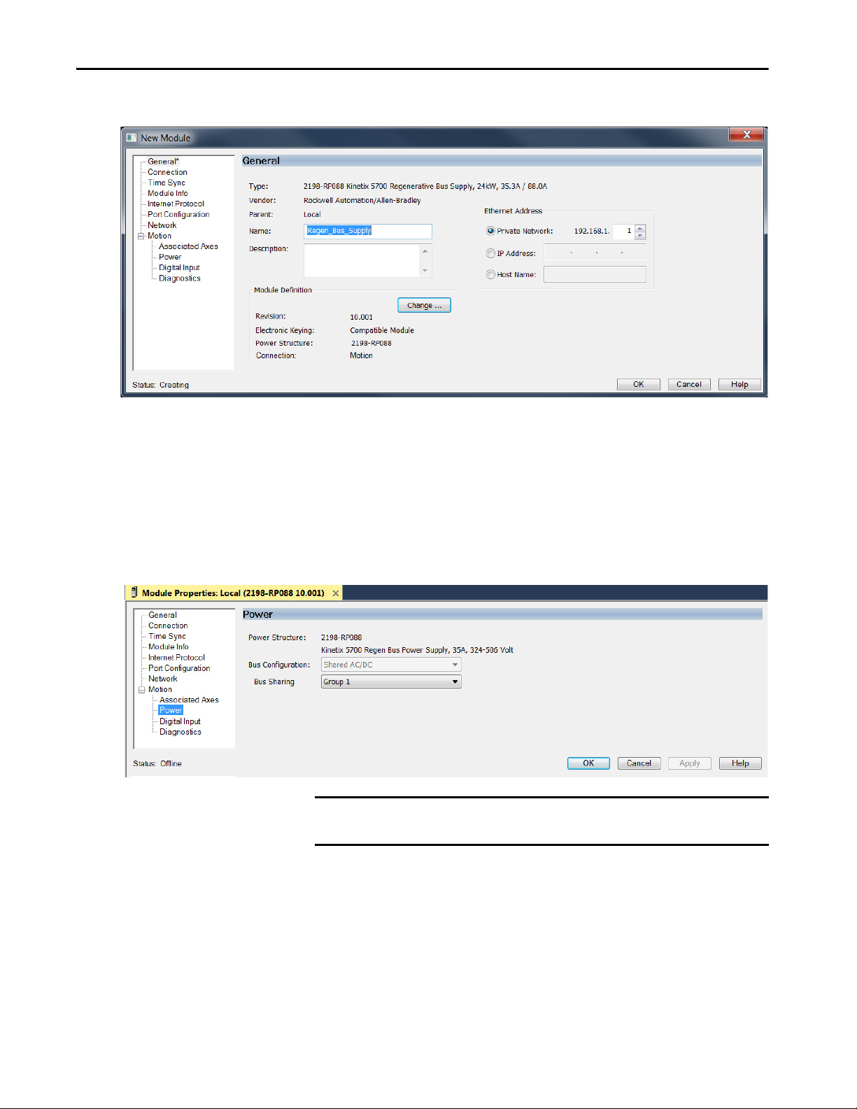
Configure Integrated Motion Control Using Kinetix 5700 Drives Chapter 4
The New Module dialog box appears.
4. Configure the new module.
a. Type the module Name.
b. Select a EtherNet/IP address option.
In this example, the Private Network address is selected.
c. Enter the address of your 2198-RPxxx regenerative bus supply.
In this example, the last octet of the address is 1.
5. Click the Power category.
IMPORTANT The Logix Designer application enforces shared-bus configuration rules
for Kinetix 5700 drives.
Rockwell Automation Publication MOTION-UM003K-EN-P - January 2019 65
Page 66

Chapter 4 Configure Integrated Motion Control Using Kinetix 5700 Drives
6. From the pull-down menus, choose the power options appropriate for
your hardware configuration.
Attribute Menu Description
Bus Configuration Shared AC/DC
Bus-sharing Group
(1) Shared AC/DC bus configuration is the default selection for regenerative bus supplies.
7. To close the New Module dialog box, click OK.
8. Your 2198-RPxxx regenerative bus
supply appears in the Controller
Organizer under the Ethernet
network in the I/O Configuration
folder.
(1)
Applies to 2198-RPxxx regenerative bus supply modules.
•Group1
•Group2
•Group3…
Applies to any bus-sharing configuration.
ATT EN TI ON : To avoid damage to equipment all modules that are
physically connected to the same shared-bus connection system
must be part of the same Bus-sharing Group in the Logix Designer
application.
9. Click Close to close the Select Module Type dialog box.
10. Right-click the regenerative bus supply that you created in the
Controller Organizer and choose Properties.
The Module Properties dialog box appears.
TIP To configure the remaining regenerative bus supply properties, you
must close the New Module dialog box and reopen it as the Module
Properties dialog box.
66 Rockwell Automation Publication MOTION-UM003K-EN-P - January 2019
Page 67

Configure Integrated Motion Control Using Kinetix 5700 Drives Chapter 4
11. Click the Digital Input category.
12. From the Digital Input pull-down menu choose Bus Conditioner OK or
AC Line Contactor OK to monitor your DC-bus conditioner module
status or the M1 contactor status, respectively, depending on your
application.
In this example, Bus Capacitor OK is chosen. For descriptions of the
digital inputs, see Table 22 on page 79
.
13. Click the Associated Axes category.
14. Click New Axis.
Rockwell Automation Publication MOTION-UM003K-EN-P - January 2019 67
Page 68

Chapter 4 Configure Integrated Motion Control Using Kinetix 5700 Drives
The New Tag dialog box appears.
15. Ty pe th e a xis Na me .
AXIS_CIP_DRIVE is the default Data Type.
16. Click Create.
The axis (Axis_1 in this example) appears in the
Controller Organizer under Motion Groups>
Ungrouped Axes and is assigned as Axis 1.
17. Click Apply.
18. Repeat step 1
through step 17 if you have more than one 2198-RPxxx
regenerative bus supply.
68 Rockwell Automation Publication MOTION-UM003K-EN-P - January 2019
Page 69

Configure Integrated Motion Control Using Kinetix 5700 Drives Chapter 4
Continue Inverter Configuration
After you have established your Kinetix 5700 inverters in the Logix Designer
application, the feedback options must be defined for each axis. Each physical
axis supports motor and auxiliary feedback.
Table 15 - Kinetix 5700 Feedback Axis Summary
Kinetix 5700 Inverter Inverter Cat. No. Motor Feedback Auxiliary Feedback
Single-axis Inverters
Dual-axis Inverters
Follow these steps to configure the axes for your Kinetix 5700 drive system.
1. Right-click the 2198-xxxx-ERS4 inverter that you just created and
choose Properties.
The Module Properties dialog box appears.
2. Select the Associated Axes category.
2198-Sxxx-ERS3 or
2198-Sxxx-ERS4
2198-Dxxx-ERS3 or
2198-Dxxx-ERS4
1 (axis 1) 1 (axis 2)
2 (axis 1 and 3) 2 (axis 2 and 4)
In this 2198-D006-ERS4 (dual-axis inverter) example, four axes are
possible. Single-axis inverters support only two axes.
• Axis 1 and Axis 2 apply to Motor (DSL) Feedback Connector A
(Port 1) and Universal Feedback Connector A (Port 1).
• Axis 3 and Axis 4 apply to Motor (DSL) Feedback Connector B
(Port 2) and Universal Feedback Connector B (Port 2).
Rockwell Automation Publication MOTION-UM003K-EN-P - January 2019 69
Page 70

Chapter 4 Configure Integrated Motion Control Using Kinetix 5700 Drives
1
I/O-A
6
10
1
I/O-B
6
5
10
UFB-A
UFB-B
D+D-D+
D-
MF-A
MF-B
2
1
5
MOD–
NET–
UFB-A
UFB-B
D+D-D+
D-
MF-A
MF-B
Kinetix 5700
Dual-axis Inverter
Universal and DSL Hiperface
Feedback Connectors
See Detail A
Motion Safety 1
Associated Axes - Axis 1
Detail A
Motion Safety 2
Associated Axes - Axis 3
UFB-B
MF-B
UFB-A
MF-A
Figure 7 - Dual-axis Inverter Feedback
The Feedback Devices are configured for either the DSL Feedback Port
or the Universal Feedback Port.
Motor Feedback Options Description
DSL Feedback Port
Universal Feedback Port
Applies to motors and actuators compatible with the 2198-KITCON-DSL
connector kit and 2198-H2DCK converter kit (series B or later). These kits
plug into the 2-pin motor feedback (MF) connector.
Applies to motors and actuators compatible with the 2198-K57CK-D15M
universal connector kit. These kits plug into the 15-pin universal feedback
(UFB) connector.
3. From the Axis x pull-down menu, choose an axis to assign to that motor
feedback or auxiliary feedback device.
4. From the Feedback Device pull-down menu, choose either DSL
Feedback x Port or Universal Feedback x Port to associate with each
axis.
5. Click New Axis.
70 Rockwell Automation Publication MOTION-UM003K-EN-P - January 2019
Page 71

Configure Integrated Motion Control Using Kinetix 5700 Drives Chapter 4
The New Tag dialog box appears.
6. Ty pe th e a xis Na me .
AXIS_CIP_DRIVE is the default Data Type.
7. Click Create.
The axis (Axis_1 in this example) appears in the
Controller Organizer under Motion Groups>
Ungrouped Axes and is assigned as Axis 1.
8. Click Apply.
9. Repeat step 1
through step 6 for each 2198-xxxx-ERSx servo drive.
Rockwell Automation Publication MOTION-UM003K-EN-P - January 2019 71
Page 72

Chapter 4 Configure Integrated Motion Control Using Kinetix 5700 Drives
This example shows the
2198-Sxxx-ERSx single-axis inverters
that you can choose from.
This example shows the
2198-Dxxx-ERSx dual-axis inverters
that you can choose from.
Configure the Inverter Drives
This procedure applies to single-axis and dual-axis inverters with hard-wired or
integrated safety connections. In this example, a 2198-D006-ERS4 dual-axis
inverter is configured.
Follow these steps to configure Kinetix 5700 inverter drives.
1. Above the DC-bus power supply (converter) you created, right-click
Ethernet and choose New Module.
The Select Module Type dialog box appears.
2. Enter 2198 to narrow your choices and select your 2198-xxxx-ERS3 or
2198-xxxx-ERS4 inverter as appropriate for your hardware
configuration.
72 Rockwell Automation Publication MOTION-UM003K-EN-P - January 2019
Page 73

Configure Integrated Motion Control Using Kinetix 5700 Drives Chapter 4
3. Click Create.
The New Module dialog box appears.
4. Configure the new drive.
a. Type the drive Name.
b. Select an EtherNet/IP address option.
In this example, the Private Network address is selected.
c. Enter the address of your 2198-xxxx-ERSx inverter.
In this example, the last octet of the address is 6.
d. Click Advanced if using network address translation with safety
connection to add drive module configured IP address.
The fields to configure in the Module Definition dialog box are dependent on
your drive, Studio 5000 Logix Designer application version, and drive
firmware revision. Use the following table to navigate to the series of steps that
are intended for your drive system.
Table 16 - How to Navigate Module Definition
For Drive Cat. No. Studio 5000
2198-xxxx-ERS3 30 or earlier 7 or earlier Configure Module Definition on page 74
2198-xxxx-ERS3 (Series B)
2198-xxxx-ERS4
Logix Designer
Application
Versi on
31 or later 9 or later Configure Module Definition on page 74
Drive Firmware
Revision
Go to:
Rockwell Automation Publication MOTION-UM003K-EN-P - January 2019 73
Page 74
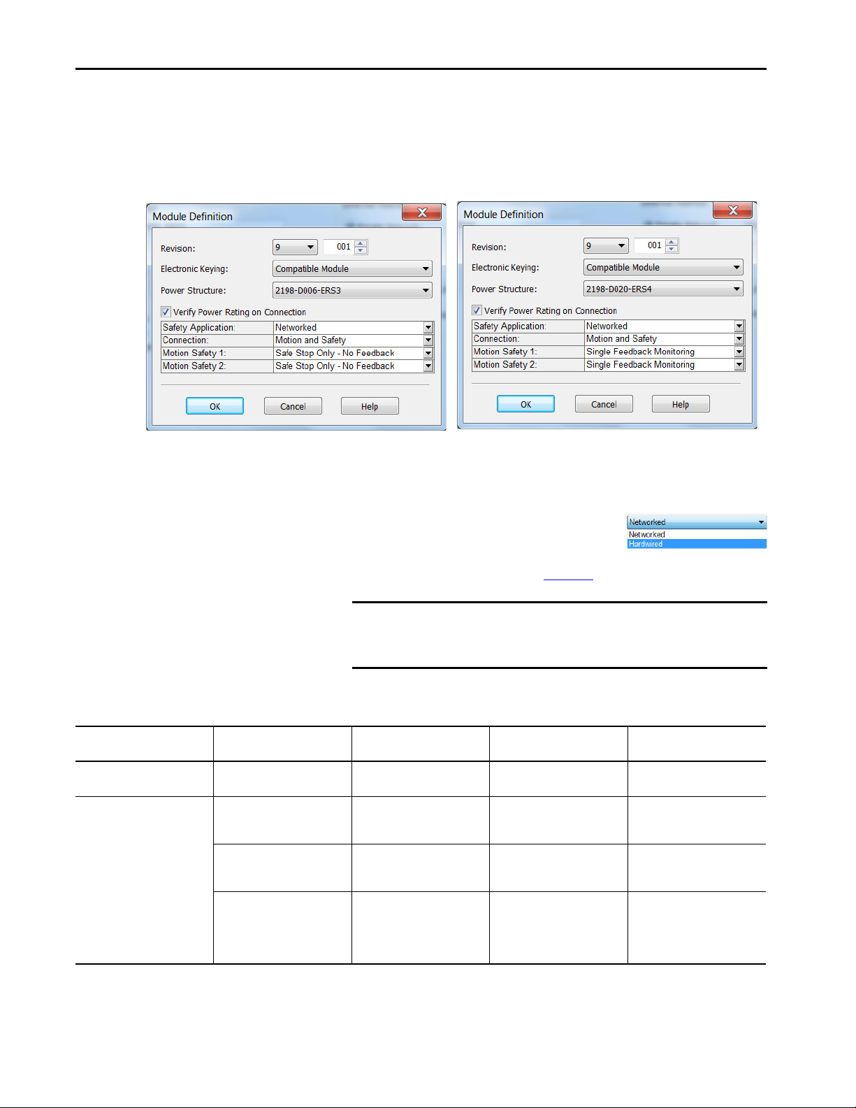
Chapter 4 Configure Integrated Motion Control Using Kinetix 5700 Drives
Configure Module Definition
1. Under Module Definition click Change.
The Module Definition dialog box appears.
Depending on the Module Definition revision selection, alternate
product features and feedback types can be selected. However, 2198xxxx-ERS4 drives only appear in drive firmware revision 9.001 or later.
2. From the Safety Application pull-down
menu, choose between Hardwired for
Hardwired STO mode or Networked for an
integrated safety application (see Ta b l e 1 7
for definitions).
IMPORTANT If the STO bypass jumper wires were applied during machine
commissioning or maintenance, they must be removed before the
drive can operate in Integrated (Networked) safety mode.
Table 17 - Safety Application Definitions
Safety Application Mode
Hardwired Hardwire d STO 2198-xxxx-ERS3 Motion Only • ControlLogix® 5570
Networked Integrated STO 2198-xxxx-ERS3 • Motion and Safety
(1) For 2198-Dxxx-ERS4 (dual-axis) inverters, you must configure axis 1 and 3 as Networked or Hardwired, they cannot be mixed.
(2) Where a ControlLogix or CompactLogix (non-safety) controller is specified, a GuardLogix or Compact GuardLogix controller is backwards compatible, but not necessary for the specified safety
application, function, and connection. Also, GuardLogix 5580 and Compact GuardLogix 5380 controllers are backwards compatible with GuardLogix 5570 and Compact GuardLogix 5370 controllers.
(1)
Safety Functions Minimum Drive Module
•Integrated STO
• Timed SS1
•Integrated STO
• Timed SS1
• Monitored SS1
• Controller-based safety
functions
Required
2198-xxxx-ERS3 • Motion and Safety
2198-xxxx-ERS4 • Motion and Safety
(2)
Drive Module Connection
Options
•Motion Only
• Safety Only
•Motion Only
• Safety Only
•Motion Only
• Safety Only
Minimum Controller
(2)
Required
• CompactLogix™ 5370
• GuardLogix® 5570
• CompactLogix 5370
• GuardLogix 5570
• CompactLogix 5370
• GuardLogix 5580
• CompactLogix 5380
74 Rockwell Automation Publication MOTION-UM003K-EN-P - January 2019
Page 75

Configure Integrated Motion Control Using Kinetix 5700 Drives Chapter 4
3. From the Connection pull-down menu,
choose the Connection mode for your
motion application (see Ta b l e 1 8
for
definitions).
TIP When ‘Safety’ appears in the Connection mode, integrated safety is
implied.
Table 18 - Module Connection Definitions
Connection Mode Safety Options Description
Motion and Safety Integrated mode This controller manages the motion connections and
Motion Only • Hard-wired STO mode
• Integrated mode if there is a
secondary safety controller
Safety Only Integrated mode • This controller manages the integrated STO.
integrated STO.
• This controller manages the motion connections.
• The hard-wired safety inputs control the hard-wired
STO. Another controller that has a Safety-only
connection to the drive manages the integrated STO.
• Another controller that has a Motion-only
connection to the drive manages the motion
connections.
Motion Safety Mode
STO Only
Safe Stop Only No Feedback
Single Feedback
Monitoring
Dual Feedback
Monitoring
Safety Application
Mode
Networked
4. From the Motion Safety x pull-down menu,
choose the integrated safety type (see
Ta b l e 1 9
for definitions).
'Motion Safety' applies to 2198-Sxxx-ERS4 (single-axis) inverters.
'Motion Safety 1' and 'Motion Safety 2' applies to 2198-Dxxx-ERS4
(dual-axis) inverters.
Motion Safety and Motion Safety 1 align with Axis 1 configured in
Associated Axes. Motion Safety 2 aligns with Axis 3 configured in
Associated Axes.
Table 19 - Motion Safety Definitions
Module Connection
Options
• Motion and Safety
•Safety Only
Description
2198-xxxx-ERS3 (series A and B): STO function only.
• 2198-xxxx-ERS4: STO function and Timed SS1 safe stop functions are available.
• 2198-xxxx-ERS3 (series B): STO function and Timed SS1 safe stop functions are available.
Primary feedback is used in the safety object for safe monitoring. The feedback can be a SIL rated
Hiperface DSL encoder, for example, a VPL-B1003P-Q or W motor used in the DSL Feedback port. This
can also be a Sine/Cosine or EnDat device, for example, an MPL-B310P-M motor used in the Universal
Feedback port. See the Kinetix 5700 Safe Monitor Functions Safety Reference Manual, publication
2198-RM001
In addition to primary feedback, an external feedback device is used to improve SIL levels. For
example, the Bulletin 842HR type encoder can be used in the Universal Feedback port as a Sine/
Cosine device. See the Kinetix 5700 Safe Monitor Functions Safety Reference Manual, publication
2198-RM001
, to evaluate SIL levels possible with one feedback device.
, to evaluate SIL levels possible with two feedback devices.
Rockwell Automation Publication MOTION-UM003K-EN-P - January 2019 75
Page 76

Chapter 4 Configure Integrated Motion Control Using Kinetix 5700 Drives
The Safety Network Number (SNN) field populates automatically
when the Connection mode includes an integrated Motion and Safety
or Safety-only connection. For a detailed explanation of the safety
network number, refer to the appropriate GuardLogix controller
publication as defined in Additional Resources on page 9
5. To close the Module Definition dialog box, click OK.
6. Click Apply.
Configure the Power and Safety Options
1. Click the Power category.
.
IMPORTANT The Logix Designer application enforces shared-bus configuration rules for
Kinetix 5700 drives.
76 Rockwell Automation Publication MOTION-UM003K-EN-P - January 2019
Page 77

Configure Integrated Motion Control Using Kinetix 5700 Drives Chapter 4
2. From the pull-down menus, choose the power options appropriate for
your hardware configuration.
Table 20 - Power Configuration Options
Attribute Menu Description
(2)
Shared DC
Bus Configuration
Bus Sharing Group
(1) For more information on bus-sharing groups, refer to the Kinetix 5700 servo drives User Manual, publication 2198-UM002.
(2) Shared DC bus configuration is the default selection for single-axis and dual-axis inverters.
(3) Because the 8720MC-RPS unit is not an EtherNet/IP network device, the Logix 5000™ controller does not communicate with it.
The designated inverter, configured as the Shared DC - Non-CIP Motion Converter, monitors the 8720MC-RPS unit status through
a digital input (Regen OK) and communicates with the other inverters to signal when the DC-bus voltage is present.
Shared DC - Non-CIP Motion
Conver ter
(1) (3)
•Group1
•Group2
•Group3…
(3)
Applies to 2198-Sxxx-ERSx and 2198-Dxxx-ERSx
inverter drives.
Applies to the designated inverter in drive systems
that are powered by the 8720MC-RPS regenerative
power supply.
Applies to any bus-sharing configuration.
ATT EN TI ON : To avoid damage to equipment all modules that are
physically connected to the same shared-bus connection system
must be part of the same Bus-sharing Group in the Studio 5000
Logix Designer application.
3. To close the Module Properties dialog box, click OK.
4. To close the Select Module Type dialog box, click close.
Your 2198-xxxx-ERS4 inverter
appears in the Controller
Organizer under the Ethernet
network in the
I/O Configuration folder.
5. Right-click the drive that you created in the Controller Organizer and
choose Properties.
The Module Properties dialog box appears.
If Then
Your application includes integrated safety
Your application includes hard-wired safety or has
no safety connections
Go to step 6 on page 77.
Go to Create an Associated Axis and Establish
Feedback Assignments for an Inverter Drive on page
80.
6. Click the Safety category.
Rockwell Automation Publication MOTION-UM003K-EN-P - January 2019 77
Page 78

Chapter 4 Configure Integrated Motion Control Using Kinetix 5700 Drives
7. The connection between the owner and the 2198-xxxx-ERSx inverter is
based on the following:
• Servo drive safety network number
•GuardLogix slot number
• GuardLogix safety network number
• Path from the GuardLogix controller to the 2198-xxxx-ERSx drive
• Configuration signature
If any differences are detected, the connection between the GuardLogix
controller and the 2198-xxxx-ERSx inverter is lost, and the yellow yield
icon appears in the controller project tree after you download the
program.
8. Click Advanced.
The Advanced Connection Reaction Time Limit Configuration dialog
box appears.
Analyze each safety channel to determine the appropriate settings. The
smallest Input RPI allowed is 6 ms. The selection of small RPI values
consumes network bandwidth and can cause spurious trips because
other devices cannot get access to the network.
For more information about the Advanced Connection Reaction Time
Limit Configuration, refer to the appropriate GuardLogix or Compact
GuardLogix Controllers User Manual, which is listed in Additional
Resources on page 9.
9. To close the Advanced dialog box, click OK.
10. To save the Safety category parameters, click apply.
78 Rockwell Automation Publication MOTION-UM003K-EN-P - January 2019
Page 79

Configure Integrated Motion Control Using Kinetix 5700 Drives Chapter 4
Configure Digital Inputs
Figure 8 - Digital Input Tab for the Kinetix 5700 Drive
Table 21 - Module Properties: Kinetix 5700 Digital Input Tab Descriptions
Parameter Description
Digital Input 1
Digital Input 2
Digital Input 3
Digital Input 4
Choose one of these values for Digital Input 1 and 2:
• Unassigned
•Enable
• Home
• Registration 1
• Registration 2
• Positive Overtravel
• Negative Overtravel
• Regeneration OK
• AC Line Contactor OK
•Bus Capacitor OK
• Bus Conditioner OK
•Shunt Thermal Switch OK
Table 22 - Understand Digital Input Functions
Drive Module
Functions Description
2198-Pxxx
2198-xxxx-ERSx
2198-RPxxx
Enable A 24V DC input is applied to this terminal as a condition to enable each module. X X X
Home
Registration 1
Registration 2 –X–
Positive Overtravel
Negative Overtravel
Regeneration OK
AC Line Contactor OK An active indicates that the AC Line Contactor is working correctly and is capable of charging the DC bus. X
An active state indicates to a homing sequence that the referencing sensor has been seen. Typically, a transition of this signal is used to
establish a reference position for the machine axis.
An inactive-to-active transition (also known as a positive transition) or active-to-inactive transition (also known as a negative
transition) is used to latch position values for use in registration moves.
The positive/negative limit switch (normally closed contact) inputs for each axis require 24V DC (nominal). – X –
In the active state the inverters can be enabled. An inactive state indicates that the Bulletin 8720MC-RPS un it is not ready to supply DCbus power. The inverters cannot be enabled.
When a bus group is supplied by an 8720MC-RPS unit, one inverter in the bus group must be configured in the Logix Designer
application as Shared-DC Non-CIP Motion™ Converter and assigned to Regeneration OK. This signal is wired from RDY on the
8720MC-RPS unit and indicates to the Kinetix 5700 drive system that the 8720MC-RPS unit is ready to supply power. Enabled inverters
enumerate a Bus Power Sharing fault if the Regeneration OK input goes inactive.
–X–
–X–
–X–
Rockwell Automation Publication MOTION-UM003K-EN-P - January 2019 79
Page 80

Chapter 4 Configure Integrated Motion Control Using Kinetix 5700 Drives
Functions Description
Bus Capacitor OK
Shunt Thermal
Switch OK
Bus Conditioner OK
You can configure this input in the Logix Designer application and wire the module status (MS) output from the 2198-CAPMOD-2240
capacitor module to indicate to the inver ter that a major fault is present on the capacitor module.
When the 2198-R014, 2198-R031, or 2198-R127 external shunt resistor is wired to the DC-bus power supply, this input must be
configured in the Logix Designer application to monitor the status of the external shunt module thermal switch and assigned to Shunt
thermal switch OK. This function does not apply to the 2198-R004 shunt resistor. You can also use this input to monitor the status of an
active shunt module in the system that is connected via the capacitor module or an extension module.
You can configure this input in the Logix Designer application and wire the module status (MS) output from the 2198-DCBUSCONDRP312 conditioner module to indicate to the inverter that a major fault is present on the conditioner module.
Create an Associated Axis and Establish Feedback Assignments for an Inverter Drive
Drive Module
2198-Pxxx
2198-xxxx-ERSx
2198-RPxxx
XXX
XXX
XXX
After you establish your Kinetix 5700 inverters in the Studio 5000 Logix
Designer application, the feedback options must be defined for each axis. Each
physical axis supports motor and auxiliary feedback.
Table 23 - Kinetix 5700 Feedback Axis Summary
Kinetix 5700 Inverter Inverter Cat. No. Motor Feedback Auxiliary Feedback
Single-axis Inverters
Dual-axis Inverters
2198-Sxxx-ERS3 or
2198-Sxxx-ERS4
2198-Dxxx-ERS3 or
2198-Dxxx-ERS4
1 (axis 1) 1 (axis 2)
2 (axis 1 and 3) 2 (axis 2 and 4)
Follow these steps to configure the axes for your Kinetix 5700 drive system.
1. Right-click the 2198-xxxx-ERS4 inverter that you created and choose
Properties.
The Module Properties dialog box appears.
80 Rockwell Automation Publication MOTION-UM003K-EN-P - January 2019
Page 81

Configure Integrated Motion Control Using Kinetix 5700 Drives Chapter 4
2. Select the Associated Axes category.
3. Click New Axis.
The New Tag dialog box appears.
4. Ty pe th e a xis Na me .
AXIS_CIP_DRIVE is the default Data Type.
5. Click Create.
Rockwell Automation Publication MOTION-UM003K-EN-P - January 2019 81
Page 82

Chapter 4 Configure Integrated Motion Control Using Kinetix 5700 Drives
The axis (Axis_1 in this example) appears in the
Controller Organizer under Motion Groups>
Ungrouped Axes and is assigned as Axis 1.
6. Click Apply.
Feedback options must be defined for each axis. Each physical axis supports
motor and auxiliary feedback.
The Kinetix 5700 drive has two or four feedback ports. The single-axis
inverters support two ports and the dual-axis inverters support four ports. Port
1 is reserved for Motor Feedback on the primary axis (Axis_1). Port 2 can be
used either as Load Feedback for the primary axis or as a Master Feedback for a
secondary feedback only axis (Axis_2).
Feedback Devices are configured for either the DSL Feedback Port or the
Universal Feedback Port.
To establish Feedback Port assignments for K5700 drives, follow these steps.
1. To access the Module Properties, double-click the Kinetix 5700 drive in
the Controller Organizer.
2. Click the Associated Axes category.
3. From the Feedback Device pull-down menus, choose either a DSL
feedback port or universal feedback port to associate with your axis.
4. Click Apply.
For more information on configuration of Feedback Properties, refer to the
Kinetix 5700 servo drives User Manual, publication 2198-UM002
82 Rockwell Automation Publication MOTION-UM003K-EN-P - January 2019
. Chapter 8,
Page 83

Configure Integrated Motion Control Using Kinetix 5700 Drives Chapter 4
Configuration Examples for a Kinetix Drive, also includes a Frequency
Control with No Feedback example on page 180
.
Create a Motion Group
To determine how many axes your controller system supports, see Table 3 on
page 12.
All axes must be added to the Motion Group in your project. If you do not
group the axes, they remain ungrouped and unavailable for use.
You must create a Motion Group for an axis to be configured properly.
Follow these steps to configure the motion group.
1. In the Controller Organizer, right-click Motion Groups and choose
New Motion Group.
The New Tag dialog box appears.
2. Type a Tag name.
3. Type a description, if desired.
4. Choose the Tag Type.
5. Choose the Scope.
6. Choose the External Access.
Rockwell Automation Publication MOTION-UM003K-EN-P - January 2019 83
Page 84

Chapter 4 Configure Integrated Motion Control Using Kinetix 5700 Drives
7. Click Create.
Your new motion group appears in the Controller Organizer under the
Motion Groups folder.
8. Right-click the new motion group and choose Properties.
The Motion Group Properties dialog box appears.
9. Click the Axis Assignment tab and move your axes (created earlier) from
Unassigned to Assigned.
Set the Base Update Period
The Base Update Period is the RPI rate for Ethernet communication between
the controller and the motion module, a Unicast connection.
There are two alternate update periods that you can configure when using the
Axis Scheduling function. See Axis Scheduling on page 145
The Base Update Period determines how often the Motion Task runs. When
the Motion Task runs, it interrupts most other tasks regardless of their priority.
The Motion Task is the part of the controller that takes care of position and
velocity information for the axes.
To set the Base Update Period, follow these steps.
1. Click the Attribute tab in the Motion Group Properties dialog box.
for details.
84 Rockwell Automation Publication MOTION-UM003K-EN-P - January 2019
Page 85

Configure Integrated Motion Control Using Kinetix 5700 Drives Chapter 4
Motion Task
Scans of Your Code, System
Overhead, and so on
0 ms 10 ms
20 ms 30 ms 40 ms
In this example, the Base Update Period = 10 ms. Every 10 ms the controller stops scanning your code and whatever else it is doing and
runs the motion planner.
2. Set the Base Update Period to 6.0…32.0 ms.
TIP Check the Last Scan time values. Typically, the value is less than
50% of the Base Update Period.
For the Kinetix 5700 drive, the minimum Base Update Rate is 1 ms.
Figure 9 - Base Update Period Example
The Base Update Period is a trade-off between updating positions of your axes
and scanning your code. In general, you do not want the Motion Task to take
more than 50% of the overall Logix controller time on average. The more axes
that you add to the Motion Group, the more time it takes to run the Motion
Ta s k .
For the ControlLogix 5560 controller, the incremental impact on the Motion
Task is roughly at 2…3 drives/ms. For the ControlLogix 5570 controller, the
incremental impact on the Motion Task is roughly at 6…8 drives/ms. Actual
impact can vary depending on axis configuration.
For detailed information on the Axis Scheduling function, Axis Assignment
tab, and Alternate Update Period Scheduling, see Axis Scheduling on
page 145.
Integrated Architecture Builder
To help you determine motion system performance, use the motion
performance calculator in the Integrated Architecture Builder (IAB).
The IAB is a graphical software tool for configuring Logix-based automation
systems. It helps you select hardware and generate bills of material for
applications that include controllers, I/O, networks, PowerFlex® drives, OnMachine™ cabling and wiring, motion control, and other devices.
You can find the software at
http://www.rockwellautomation.com/en/e-tools/configuration.html
Rockwell Automation Publication MOTION-UM003K-EN-P - January 2019 85
Page 86

Chapter 4 Configure Integrated Motion Control Using Kinetix 5700 Drives
Configure the Axis Properties
After you add the drive to your project and create the axes, use the Axis
Properties dialog boxes to configure the drive. Notice that the dialog boxes
change based on your configuration choices, for example, feedback
configuration.
Ta b l e 2 4
Table 24 - Category Dialog Boxes to Configure Drives
Category Dialog Box Perform These Tasks Page
General • Assign the axis configuration.
Motor • Specify a motor with the Data Source = Nameplate data sheet.
Motor Feedback • Select the Motor Feedback Type. 95
Load Feedback • Select the Load Feedback Type, if applicable. 97
Scaling • Configure feedback by choosing the load t ype, by entering the scaling units,
lists the basic tasks necessary configure a drive.
• Choose the feedback configuration.
• Choose the application type, if applicable.
• Choose the loop response (low, medium, or high), if applicable.
• If you have not already done so, you can create and associate an axis to a
new Motion Group and associate a drive module to the axis.
• Specify a motor with the Data Source = Catalog Number.
• Select a motor with the Data Source = Motor NV.
and by choosing the Travel mode.
• Enter the Input Transmission and Actuator ratio, if applicable.
88
91
222
The parameters that you configure on the General category dialog box result in
the presentation of attributes and parameters that are available for the
combination of your selections.
IMPORTANT All AXIS_CIP_DRIVE Axis Properties dialog boxes are dynamic. Optional
attributes and dialog boxes that are related to each integrated motion
axis you create come and go based on what combination of axis
characteristics you define.
See the Integrated Motion Reference Manual, publication MOTION-RM003
for complete information on Axis Attributes and how to apply Control Modes.
IMPORTANT Be sure to associate the drive and axis before when configuring the axis
because the drive determines what optional attributes are supported for
the axis.
,
86 Rockwell Automation Publication MOTION-UM003K-EN-P - January 2019
Page 87

Configure Integrated Motion Control Using Kinetix 5700 Drives Chapter 4
If you have already created an axis and associated in with a drive, the Associated
Module and Axis are shown on the General category of the Axis Properties
dialog box. Otherwise, you can select them here.
Figure 10 - General Category Dialog Box
^^ for an inverter
ss for a converter
The Axis Number field corresponds to the axes listed on the Associated Axes
tab of the Module Properties dialog box. Any feedback port assignments that
you made on the Associated Axes tab are also mapped to the drive when you
associate an axis and a drive.
Rockwell Automation Publication MOTION-UM003K-EN-P - January 2019 87
Page 88

Chapter 4 Configure Integrated Motion Control Using Kinetix 5700 Drives
Configure the Associated Axis and Control Mode
Now that the axis is associated to the drive module, meaningful values are
available for other axis properties.
For more information on Control Modes, see the Integrated Motion Reference
Manual, publication MOTION-RM003
.
1. In the Controller Organizer, double-click the Axis that you want to
configure.
The Axis Properties General dialog box appears.
2. Choose an Axis Configuration type. For this example, choose Position
Loop.
TIP The associated drive determines what Axis and Feedback
Configuration choices are presented.
Ta b l e 2 5
Table 25 - Compare the Axis Configuration Types for the Drives
Axis Type
Position Loop (P) Yes Yes N o N o
Vel ocit y Loo p (V ) Yes Yes N o No
Tor qu e Lo op (T ) Yes Ye s N o N o
Feedback Only (E)
Frequenc y Control (F)
Non-Regenerative
AC/DC Converter (N)
Regenerative AC/DC
Conver ter (G)
compares the axis configuration types for the drives.
Kinetix 5700
Dual-axis
Inverter
Yes Yes N o N o
Yes Yes N o N o
No No Yes No
No No No Yes
Kinetix 5700
Single-axis
Inverter
Kinetix 5700
DC Bus
Supply
Kinetix 5700
Regenerative
Bus Supply
3. In the Feedback Configuration pull-down menu, choose Motor
Feedback.
88 Rockwell Automation Publication MOTION-UM003K-EN-P - January 2019
Page 89

Configure Integrated Motion Control Using Kinetix 5700 Drives Chapter 4
Ta b l e 2 6 compares the feedback configuration types for the Kinetix
drives.
Table 26 - Compare the Feedback Configuration Types for the Drives
Feed back
Type
Kinetix 5700
Dual-axis
Inverter Type
Motor Feedback Position Loop (P),
Load Feedback Posi tion Loop (P) ,
Dual Feedback Position Loop (P) Position Loop (P)
Dual Integrator — — — —
Master Feedback Feedba ck Only (E) Feedback Only (E) — —
No Feedback
Velo city Loop ( V),
Tor que Loo p ( T)
Velo city Loop ( V)
Frequency Control
(F)
Kinetix 5700
Single-axis
Inverter Type
Position Loop (P),
Veloc ity Loo p(V ),
Torque Loop (T)
Position Loop (P),
Veloc ity Loo p(V )
Frequenc y Control
(F)
Kinetix 5700
DC Bus Power
Supply
— —
— —
— —
Non-regenerative
AC/DC Converter
(N)
4. Choose an Application Type, if applicable.
TIP The following General Options are available in an inverter configuration.
Kinetix 5700
Regenerative
Bus Supply
Regenerative
AC/DC Converter
(G)
The Application Type determines the type of motion control
application. This attribute is used to set the Gain Tuning Configuration
Bits. Ta b l e 2 7
Table 27 - Customize Gains to Tune
Application Type Kpi Kvi ihold Kvff Kaff torqLPF
(1)
Custom
Basic No No No Yes No Yes
Tracking No Yes No Yes Yes Yes
Po i nt - to - Po in t Ye s N o Ye s No No Ye s
Constant Speed No Yes No Yes No Yes
(1) If you set the type to Custom, you can control the individual gain calculations by changing the bit settings in the Gain Tuning
Configuration Bits Attribute.
Rockwell Automation Publication MOTION-UM003K-EN-P - January 2019 89
illustrates the gains established based on application type.
——————
Page 90

Chapter 4 Configure Integrated Motion Control Using Kinetix 5700 Drives
5. Choose a Loop Response, if applicable.
6. Choose a Converter Configuration, if applicable.
TIP Loop Response settings also impact the calculations that are made
that can minimize the need for you to perform an Autotune or a
Manual Tune. The loop response impacts the spacing between the
position and velocity loops and the proportional and integral gains.
This response impacts how aggressively a given profile is tracked.
TIP The following General Options are available in an converter configuration.
7. Choose a Converter Startup Method, if applicable.
90 Rockwell Automation Publication MOTION-UM003K-EN-P - January 2019
Page 91

Configure Integrated Motion Control Using Kinetix 5700 Drives Chapter 4
Specify the Motor Data Source
The Motor Data Source is where you tell the axis where the motor
configuration values are originating. You can select a motor by catalog number
from the Motion Database. You can enter motor data from a nameplate or data
sheet, or use the motor data that is contained in the drive or motor nonvolatile
memory.
On the Motor dialog box you specify what motor you want to use and where
the data is coming from:
• Specify a motor with the Data Source = Catalog Number.
• Specify a motor with the Data Source = Nameplate data sheet.
• Select a motor with the Data Source = Motor NV.
Choose the Catalog Number as the Motor Data Source
To choose a motor from the Motion Database, follow these steps.
1. If the Axis Properties dialog box is not open, double-click the axis.
2. Go to the Motor dialog box of Axis Properties.
3. From the Data Source pull-down menu, choose Catalog Number.
4. Click Change Catalog.
Rockwell Automation Publication MOTION-UM003K-EN-P - January 2019 91
Page 92

Chapter 4 Configure Integrated Motion Control Using Kinetix 5700 Drives
To reduce the size of the
list, use these filters.
5. Select a motor.
6. The Motor dialog box is now populated with all information that is
related to the motor you selected from the Motion Database.
7. Click Apply.
TIP When you use a motor catalog number as the data source, default
values are automatically set based on the Application Type and Loop
Response settings from the General dialog box.
92 Rockwell Automation Publication MOTION-UM003K-EN-P - January 2019
Page 93

Configure Integrated Motion Control Using Kinetix 5700 Drives Chapter 4
Choose Nameplate as the Motor Data Source
The Nameplate option requires you to enter the motor specification
information from the motor nameplate and the motor data sheet.
1. On the Motor dialog box of Axis Properties, from the Data Source pulldown menu, choose Nameplate data sheet.
2. Choose a motor type. The following motor types are compatible:
• Surface Mount Permanent Magnet
•Linear Permanent Magnet
•Rotary Induction
• Interior Permanent Magnet
Notice that the motor information fields are initialized to defaults.
3. Enter the parameter information from the motor Nameplate data sheet
and click Apply.
Rockwell Automation Publication MOTION-UM003K-EN-P - January 2019 93
Page 94

Chapter 4 Configure Integrated Motion Control Using Kinetix 5700 Drives
Choose Motor NV as the Motor Data Source
When you choose Motor NV as the data source, the motor attributes are
derived from nonvolatile memory of a motor-mounted smart feedback device
that is equipped with a serial interface. Only a minimal set of motor and motor
feedback (Feedback 1) attributes are required to configure the drive.
1. From the Motor dialog box of Axis Properties, choose Motor NV.
2. Choose the Motor Units that are associated with the motor, either Rev
for rotary motor or Meters for linear motor.
No other motor information is needed.
3. Click Apply.
94 Rockwell Automation Publication MOTION-UM003K-EN-P - January 2019
Page 95

Configure Integrated Motion Control Using Kinetix 5700 Drives Chapter 4
The asterisk nex t
to a category
means that you
have not applied
changes.
Display Motor Model Information
The Motor Model category displays more information that is based on the
motor type you select.
• If the motor data source is Catalog Number, this information is
populated automatically.
• If the motor data source is Nameplate data sheet, this information must
be entered manually, or by running the optional Motor Analyzer.
• If the motor data source is Motor NV, this dialog box is blank.
Assign Motor Feedback
What appears on the Motor Feedback dialog box is dependent on what you
select on the General dialog box for Feedback Configuration.
The Motor Feedback dialog box represents the information for the feedback
device that is directly coupled to the motor. This dialog box is available if the
feedback configuration that is specified on the General dialog box is anything
other than Master Feedback.
If the motor that you select has Catalog Number as the data source, all
information on this dialog box with be entered automatically. Otherwise you
have to enter the information yourself.
Attributes that are associated with the Motor Feedback dialog box are
designated as Feedback 1.
Rockwell Automation Publication MOTION-UM003K-EN-P - January 2019 95
Page 96

Chapter 4 Configure Integrated Motion Control Using Kinetix 5700 Drives
If a permanent magnet motor is selected from the Motion Database, the
Commutation Alignment is set to Controller Offset. However, if a permanent
magnet motor is specified from Nameplate data sheet, you must specify the
Commutation Alignment method. The default is set to Not Aligned.
Table 28 - Commutation Alignment Settings
Type Des cript ion
Not Aligned Not Aligned indicates that the motor is not aligned, and that the
Controller Offset Controller Offset applies the Commutation Offset value from the
Motor Offset The drive derives the commutation that is offset directly from the motor.
Self-Sense The drive automatically measures the commutation that is offset when it
Commutation Offset value is not valid. If the Commutation Offset is not
valid, the drive cannot use it to determine the commutation angle. Any
attempt to enable the drive with an invalid commutation angle results in
a Start Inhibit condition.
controller to determine the electrical angle of the motor.
transitions to the Starting state for the first time after a power cycle. This
setting generally applies to a PM motor equipped with a simple
incremental-feedback device.
In most cases, the Commutation Alignment is set to Controller Offset and the
Commutation test is run during commissioning to determine the
Commutation Offset and Polarity.
See the Integrated Motion Reference Manual, publication MOTION-RM003
for more information on axis attributes.
,
96 Rockwell Automation Publication MOTION-UM003K-EN-P - January 2019
Page 97

Configure Integrated Motion Control Using Kinetix 5700 Drives Chapter 4
For you r convenien ce, you can use this link
to the Module Properties dialog box for the
associated drive.
Configure the Load Feedback
The Load Feedback category contains the information from the feedback
device that is directly coupled to the load-side of a mechanical transmission or
actuator.
The Load Feedback category is available if the Feedback Configuration that is
specified on the General dialog box is Load or Dual.
Attributes that are associated with the Load Feedback category are designated
Feedback 2.
Unlike the Motor Feedback category, you must explicitly enter load feedbackdevice information on the Load Feedback category, including the Feedback
Type. This entry is required because the Load Feedback device is not built into
the motor.
Default values are displayed based on the Feedback Type selected.
Rockwell Automation Publication MOTION-UM003K-EN-P - January 2019 97
Page 98

Chapter 4 Configure Integrated Motion Control Using Kinetix 5700 Drives
Configure the Master Feedback
The Master Feedback category is available if the Feedback Configuration that
is specified in the General category is Master Feedback. The attributes that are
associated with the Master Feedback category are associated with Feedback 1.
Again, like the Load Feedback category, you must enter all information.
To verify that motor and feedback device are functioning properly, download
to the controller, and continue on to Hookup Tests on page 226
.
98 Rockwell Automation Publication MOTION-UM003K-EN-P - January 2019
Page 99

Chapter 5
Configure Integrated Motion Using a
PowerFlex 755 Drive
Top ic Pag e
Add a PowerFlex 755 Drive 99
Create an Associated Axis 109
Configure the Axis Properties 115
Configure the Associated Axis and Control Mode 116
Specify the Motor Data Source 119
Display Motor Model Information 123
Assign Motor Feedback 125
Add a PowerFlex 755 Drive
This chapter provides procedures on how to configure integrated motion on
the EtherNet/IP™ network control by using a PowerFlex® 755 Embedded
EtherNet/IP drive. For PowerFlex 755 configuration examples, refer to Axis
Configuration Examples for the PowerFlex 527 Drive on page 209.
Follow these instructions to add the PowerFlex 755 drive to your project.
1. Right-click the Ethernet network (node) and choose New Module.
2. Clear the small ‘select all’ checkboxes, Module Type Category, and
Ven do r F il te rs .
3. In the Module Type Vendors Filters window, check Allen-Bradley.
Rockwell Automation Publication MOTION-UM003K-EN-P - January 2019 99
Page 100

Chapter 5 Configure Integrated Motion Using a PowerFlex 755 Drive
4. In the Module Type Category Filters window, check Drive.
5. Choose the drive and click create.
6. Type a Name for the module.
7. Type a description, if desired.
8. Assign an EtherNet/IP address.
See these manuals for information about how to configure IP addresses:
• PowerFlex 755 Drive Embedded EtherNet/IP Adapter User Manual,
publication 750COM-UM001
• EtherNet/IP Network Configuration User Manual,
publication ENET-UM001
9. Under Module Definition, click Change.
100 Rockwell Automation Publication MOTION-UM003K-EN-P - January 2019
 Loading...