

Page 1

User Manual
Original Instructions
Kinetix 350 Single-axis EtherNet/IP Servo Drives
Catalog Numbers 2097-V31PR0-LM, 2097-V31PR2-LM,
2097-V32PR0-LM, 2097-V32PR2-LM, 2097-V32PR4-LM,
2097-V33PR1-LM, 2097-V33PR3-LM, 2097-V33PR5-LM, 2097-V33PR6-LM,
2097-V34PR3-LM, 2097-V34PR5-LM, 2097-V34PR6-LM
Page 2
Important User Information
Read this document and the documents listed in the additional resources section about installation, configuration, and
operation of this equipment before you install, configure, operate, or maintain this product. Users are required to
familiarize themselves with installation and wiring instructions in addition to requirements of all applicable codes, laws,
and standards.
Activities including installation, adjustments, putting into service, use, assembly, disassembly, and maintenance are
required to be carried out by suitably trained personnel in accordance with applicable code of practice.
If this equipment is used in a manner not specified by the manufacturer, the protection provided by the equipment may
be impaired.
In no event will Rockwell Automation, Inc. be responsible or liable for indirect or consequential damages resulting from
the use or application of this equipment.
The examples and diagrams in this manual are included solely for illustrative purposes. Because of the many variables and
requirements associated with any particular installation, Rockwell Automation, Inc. cannot assume responsibility or
liability for actual use based on the examples and diagrams.
No patent liability is assumed by Rockwell Automation, Inc. with respect to use of information, circuits, equipment, or
software described in this manual.
Reproduction of the contents of this manual, in whole or in part, without written permission of Rockwell Automation,
Inc., is prohibited.
Throughout this manual, when necessary, we use notes to make you aware of safety considerations.
WARNING: Identifies information about practices or circumstances that can cause an explosion in a hazardous
environment, which may lead to personal injury or death, property damage, or economic loss.
ATTENTION: Identifies information about practices or circumstances that can lead to personal injury or death, property
damage, or economic loss. Attentions help you identify a hazard, avoid a hazard, and recognize the consequence.
IMPORTANT Identifies information that is critical for successful application and understanding of the product.
Labels may also be on or inside the equipment to provide specific precautions.
SHOCK HAZARD: Labels may be on or inside the equipment, for example, a drive or motor, to alert people that dangerous
voltage may be present.
BURN HAZARD: Labels may be on or inside the equipment, for example, a drive or motor, to alert people that surfaces may
reach dangerous temperatures.
ARC FLASH HAZARD: Labels may be on or inside the equipment, for example, a motor control center, to alert people to
potential Arc Flash. Arc Flash will cause severe injury or death. Wear proper Personal Protective Equipment (PPE). Follow ALL
Regulatory requirements for safe work practices and for Personal Protective Equipment (PPE).
Page 3

Summary of Changes
This manual contains new and updated information as indicated in the
following table.
Top ic Pag e
Add a reference to the Motion System Tuning Application Techniques, publication
MOTION-AT005
Added a footnote to Figure 1 - Typical Kinetix 350 Drive Installation 13
Added the 2198-ABQE Encoder Output module to typical communication
configurations.
Updated Input Power Circuit-protection Specifications table 19
Corrected the description of REG digital input signal 39
Add an MOV (199-MSMD1) as an option to Brake Wiring Schematic 43
Added a reference to Appendix C 52
Changed the IMPORTANT statement to an ATTENTION statement and added a
reference to App endix C
Changed footnote to include an equivalent diode 67
Modified Important statement Ethernet Cable Connections section 74
Added footnote to Figure 44 - Ethernet Wiring Example - External Switch 75
Added descriptions for status indicators StAt, Ht, buS, Curr 78
Added an Attention statement 86
Added a link Motion System Tuning Application Techniques, publication MOTIONAT0 0 5
Corrected the Attention statement under Troubleshooting the Safe Torque-off
Funct ion
Updated Figure 49 -Single-axis Relay Configuration (Stop Category 0) with
Automatic Reset
Added Figure 50 - Single-axis Relay Configuration (Stop Category 0) with Manual
Reset
Added Safety Input and Output Schematics 110
Duplicated the Important statement that describes the fault detection ability of
TTL encoders
Added Appendix C - Leakage Currents 151
9
14
53
94
103
108
109
124
Rockwell Automation Publication 2097-UM002D-EN-P - April 2017 3
Page 4

Summary of Changes
Notes:
4 Rockwell Automation Publication 2097-UM002D-EN-P - April 2017
Page 5

Table of Contents
Preface
Conventions. . . . . . . . . . . . . . . . . . . . . . . . . . . . . . . . . . . . . . . . . . . . . . . . . . . 9
Additional Resources . . . . . . . . . . . . . . . . . . . . . . . . . . . . . . . . . . . . . . . . . . . 9
Chapter 1
Start About the Kinetix 350 Drive System. . . . . . . . . . . . . . . . . . . . . . . . . . . . 12
Catalog Number Explanation . . . . . . . . . . . . . . . . . . . . . . . . . . . . . . . . . . 15
Agency Compliance . . . . . . . . . . . . . . . . . . . . . . . . . . . . . . . . . . . . . . . . . . . 16
CE Requirements. . . . . . . . . . . . . . . . . . . . . . . . . . . . . . . . . . . . . . . . . . 16
Chapter 2
Install the Kinetix 350 Drive
System
System Design Guidelines. . . . . . . . . . . . . . . . . . . . . . . . . . . . . . . . . . . . . . 17
System Mounting Requirements . . . . . . . . . . . . . . . . . . . . . . . . . . . . 17
Circuit Breaker/Fuse Selection . . . . . . . . . . . . . . . . . . . . . . . . . . . . . 18
Contactor Ratings . . . . . . . . . . . . . . . . . . . . . . . . . . . . . . . . . . . . . . . . . 20
Transformer Selection . . . . . . . . . . . . . . . . . . . . . . . . . . . . . . . . . . . . . 20
Transformer Specifications for Input Power . . . . . . . . . . . . . . . . . 21
Enclosure Selection . . . . . . . . . . . . . . . . . . . . . . . . . . . . . . . . . . . . . . . . 21
Power Dissipation Specifications. . . . . . . . . . . . . . . . . . . . . . . . . . . . 22
Minimum Clearance Requirements . . . . . . . . . . . . . . . . . . . . . . . . . 23
Electrical Noise Reduction . . . . . . . . . . . . . . . . . . . . . . . . . . . . . . . . . . . . . 24
Bonding Drives. . . . . . . . . . . . . . . . . . . . . . . . . . . . . . . . . . . . . . . . . . . . 24
Bonding Multiple Subpanels. . . . . . . . . . . . . . . . . . . . . . . . . . . . . . . . 26
Establish Noise Zones. . . . . . . . . . . . . . . . . . . . . . . . . . . . . . . . . . . . . . 27
Cable Categories for Kinetix 350 Drive Components. . . . . . . . . 29
Noise Reduction Guidelines for Drive Accessories. . . . . . . . . . . . 29
Mount Your Kinetix 350 Drive. . . . . . . . . . . . . . . . . . . . . . . . . . . . . . . . . 32
Chapter 3
Kinetix 350 Drive Connector Data Kinetix 350 Drive Connectors and Indicators . . . . . . . . . . . . . . . . . . . 34
Safe Torque-off Connector Pinout. . . . . . . . . . . . . . . . . . . . . . . . . . 35
I/O Connector Pinout . . . . . . . . . . . . . . . . . . . . . . . . . . . . . . . . . . . . 36
Motor Feedback (MF) Connector Pinout . . . . . . . . . . . . . . . . . . . 37
Ethernet Communication Connector Pinout . . . . . . . . . . . . . . . . 37
AC Input Power Connector Pinout. . . . . . . . . . . . . . . . . . . . . . . . . 38
Back-up Power Connector Pinout . . . . . . . . . . . . . . . . . . . . . . . . . . 38
Shunt Resistor and DC Bus Connector Pinout. . . . . . . . . . . . . . . 38
Motor Power Connector Pinout . . . . . . . . . . . . . . . . . . . . . . . . . . . . 38
Control Signal Specifications. . . . . . . . . . . . . . . . . . . . . . . . . . . . . . . . . . . 39
Digital Inputs . . . . . . . . . . . . . . . . . . . . . . . . . . . . . . . . . . . . . . . . . . . . . 39
Motor Brake Output . . . . . . . . . . . . . . . . . . . . . . . . . . . . . . . . . . . . . . 42
Ethernet Communication Specifications . . . . . . . . . . . . . . . . . . . . 43
24V DC Back-up Power Specifications . . . . . . . . . . . . . . . . . . . . . . 43
Motor Feedback Specifications . . . . . . . . . . . . . . . . . . . . . . . . . . . . . . . . . 44
Rockwell Automation Publication 2097-UM002D-EN-P - April 2017 5
Page 6

Table of Contents
Connect the Kinetix 350 Drive
System
Feedback Power Supply . . . . . . . . . . . . . . . . . . . . . . . . . . . . . . . . . . . . 49
Chapter 4
Basic Wiring Requirements . . . . . . . . . . . . . . . . . . . . . . . . . . . . . . . . . . . . 51
Recommended Cables . . . . . . . . . . . . . . . . . . . . . . . . . . . . . . . . . . . . . 52
Route Power and Signal Wiring. . . . . . . . . . . . . . . . . . . . . . . . . . . . . 52
Determine the Input Power Configuration . . . . . . . . . . . . . . . . . . . . . . 52
Three-phase Power Wired to Three-phase Drives . . . . . . . . . . . . 53
Single-phase Power Wired to Single-phase Drives . . . . . . . . . . . . 54
Voltage Doubler Operation . . . . . . . . . . . . . . . . . . . . . . . . . . . . . . . . 54
Isolation Transformer in Grounded Power Configurations . . . 55
Three-phase Power Wired to Single-phase Drives . . . . . . . . . . . . 55
Voiding of CE Compliance. . . . . . . . . . . . . . . . . . . . . . . . . . . . . . . . . 57
Grounding Your Kinetix 350 Drive System. . . . . . . . . . . . . . . . . . . . . . 58
Ground Your Drive to the System Subpanel . . . . . . . . . . . . . . . . . 58
Ground Multiple Subpanels . . . . . . . . . . . . . . . . . . . . . . . . . . . . . . . . 59
Power Wiring Requirements . . . . . . . . . . . . . . . . . . . . . . . . . . . . . . . . . . . 60
Wiring Guidelines. . . . . . . . . . . . . . . . . . . . . . . . . . . . . . . . . . . . . . . . . . . . . 61
Wiring the Kinetix 350 Drive Connectors. . . . . . . . . . . . . . . . . . . . . . . 62
Wire the Safe Torque-off (STO) Connector . . . . . . . . . . . . . . . . . 62
Wire the Back-up Power (BP) Connector . . . . . . . . . . . . . . . . . . . 62
Wire the Input Power (IPD) Connector. . . . . . . . . . . . . . . . . . . . . 63
Wire the Motor Power (MP) Connector . . . . . . . . . . . . . . . . . . . . 64
Apply the Motor Cable Shield Clamp. . . . . . . . . . . . . . . . . . . . . . . . . . . 69
Feedback and I/O Cable Connections . . . . . . . . . . . . . . . . . . . . . . . . . . 70
Flying-lead Feedback Cable Pin-outs . . . . . . . . . . . . . . . . . . . . . . . . 71
Wiring the Feedback and I/O Connectors . . . . . . . . . . . . . . . . . . . . . . 72
Wire the I/O Connector . . . . . . . . . . . . . . . . . . . . . . . . . . . . . . . . . . . 72
Wire the Low-profile Connector Kit . . . . . . . . . . . . . . . . . . . . . . . . 73
Shunt Resistor Connections. . . . . . . . . . . . . . . . . . . . . . . . . . . . . . . . . . . . 74
Ethernet Cable Connections . . . . . . . . . . . . . . . . . . . . . . . . . . . . . . . . . . . 74
Chapter 5
Configure and Start up the
Kinetix 350 Drive System
6 Rockwell Automation Publication 2097-UM002D-EN-P - April 2017
Keypad Input . . . . . . . . . . . . . . . . . . . . . . . . . . . . . . . . . . . . . . . . . . . . . . . . . 78
Status Indicators. . . . . . . . . . . . . . . . . . . . . . . . . . . . . . . . . . . . . . . . . . . 79
Configure the Kinetix 350 Drive Ethernet IP Address. . . . . . . . . . . . 81
Ethernet Connection . . . . . . . . . . . . . . . . . . . . . . . . . . . . . . . . . . . . . . 81
Kinetix 350 Drive Ethernet Port Configuration. . . . . . . . . . . . . . 81
Obtain the Kinetix 350 Drives’ Current Ethernet Settings . . . . 81
Configure the IP Address Manually (Static Address) . . . . . . . . . 82
Configure the IP Address Automatically (Dynamic Address). . 83
Configure the Logix5000 EtherNet/IP Controller . . . . . . . . . . . . . . . 84
Configure the Logix5000 Controller . . . . . . . . . . . . . . . . . . . . . . . . 84
Configure the Kinetix 350 Drive. . . . . . . . . . . . . . . . . . . . . . . . . . . . 86
Configure the Motion Group. . . . . . . . . . . . . . . . . . . . . . . . . . . . . . . 89
Configure Axis Properties . . . . . . . . . . . . . . . . . . . . . . . . . . . . . . . . . . 90
Page 7

Kinetix 350 Drive Safe Torque-off
Feature
Table of Contents
Download the Program . . . . . . . . . . . . . . . . . . . . . . . . . . . . . . . . . . . . 93
Apply Power to the Kinetix 350 Drive . . . . . . . . . . . . . . . . . . . . . . . . . . 93
Test and Tune the Axes. . . . . . . . . . . . . . . . . . . . . . . . . . . . . . . . . . . . . . . . 94
Test the Axes. . . . . . . . . . . . . . . . . . . . . . . . . . . . . . . . . . . . . . . . . . . . . . 94
Tune the Axes. . . . . . . . . . . . . . . . . . . . . . . . . . . . . . . . . . . . . . . . . . . . . 97
Disable EnableInputChecking by Using a Logix
Designer Message Instruction . . . . . . . . . . . . . . . . . . . . 100
Chapter 6
Certification . . . . . . . . . . . . . . . . . . . . . . . . . . . . . . . . . . . . . . . . . . . . . . . . . 101
Important Safety Considerations . . . . . . . . . . . . . . . . . . . . . . . . . . 101
Safety Category 3 Requirements . . . . . . . . . . . . . . . . . . . . . . . . . . . 102
Stop Category Definition . . . . . . . . . . . . . . . . . . . . . . . . . . . . . . . . . 102
Performance Level and Safety Integrity Level (SIL) CL2 . . . . . 102
Description of Operation . . . . . . . . . . . . . . . . . . . . . . . . . . . . . . . . . . . . . 102
Troubleshoot the Safe Torque-off Function . . . . . . . . . . . . . . . . 103
PFD and PFH Definitions . . . . . . . . . . . . . . . . . . . . . . . . . . . . . . . . . . . . 103
PFD and PFH Data . . . . . . . . . . . . . . . . . . . . . . . . . . . . . . . . . . . . . . . . . . 103
Safe Torque-off Connector Data . . . . . . . . . . . . . . . . . . . . . . . . . . . . . . 104
STO Connector Pinouts . . . . . . . . . . . . . . . . . . . . . . . . . . . . . . . . . . 104
Wiring Your Safe Torque-off Circuit . . . . . . . . . . . . . . . . . . . . . . . . . . 105
European Union Directives . . . . . . . . . . . . . . . . . . . . . . . . . . . . . . . 105
Safe Torque-off Wiring Requirements. . . . . . . . . . . . . . . . . . . . . . 106
Kinetix 350 Drive Safe Torque-off Feature . . . . . . . . . . . . . . . . . . . . . 107
Safe Torque-off Feature Bypass . . . . . . . . . . . . . . . . . . . . . . . . . . . . 107
Kinetix 350 Drive Safe Torque-off Wiring Diagrams . . . . . . . . . . . . 108
Safe Torque-off Signal Specifications. . . . . . . . . . . . . . . . . . . . . . . . . . . 109
Safety Input and Output Schematics . . . . . . . . . . . . . . . . . . . . . . . . . . . 110
Chapter 7
Troubleshoot the Kinetix 350
Drive
Safety Precautions . . . . . . . . . . . . . . . . . . . . . . . . . . . . . . . . . . . . . . . . . . . . 111
Interpret Status Indicators . . . . . . . . . . . . . . . . . . . . . . . . . . . . . . . . . . . . 112
Four-digit Display Messages . . . . . . . . . . . . . . . . . . . . . . . . . . . . . . . 112
Error Codes. . . . . . . . . . . . . . . . . . . . . . . . . . . . . . . . . . . . . . . . . . . . . . 113
Fault Codes . . . . . . . . . . . . . . . . . . . . . . . . . . . . . . . . . . . . . . . . . . . . . . 113
Status Indicators. . . . . . . . . . . . . . . . . . . . . . . . . . . . . . . . . . . . . . . . . . 119
General System Behavior. . . . . . . . . . . . . . . . . . . . . . . . . . . . . . . . . . . . . . 120
Logix5000 Controller and Drive Behavior. . . . . . . . . . . . . . . . . . . . . . 124
Kinetix 350 Drive Exception Behavior . . . . . . . . . . . . . . . . . . . . . 124
Web Server Interface . . . . . . . . . . . . . . . . . . . . . . . . . . . . . . . . . . . . . . . . . 128
Appendix A
Interconnect Diagrams Interconnect Diagram Notes . . . . . . . . . . . . . . . . . . . . . . . . . . . . . . . . . . 130
Power Wiring Examples . . . . . . . . . . . . . . . . . . . . . . . . . . . . . . . . . . . . . . 131
Shunt Resistor Wiring Example. . . . . . . . . . . . . . . . . . . . . . . . . . . . 133
Kinetix 350 Drive/Rotary Motor Wiring Examples . . . . . . . . . . . . . 134
Rockwell Automation Publication 2097-UM002D-EN-P - April 2017 7
Page 8

Table of Contents
Kinetix 350 Drive/Actuator Wiring Examples . . . . . . . . . . . . . . . . . . 137
Motor Brake Currents . . . . . . . . . . . . . . . . . . . . . . . . . . . . . . . . . . . . . . . . 140
System Block Diagrams . . . . . . . . . . . . . . . . . . . . . . . . . . . . . . . . . . . . . . . 141
Appendix B
Upgrade the Kinetix 350 Drive
Firmware
Before You Begin. . . . . . . . . . . . . . . . . . . . . . . . . . . . . . . . . . . . . . . . . . . . . 143
Configure Logix5000 Communication. . . . . . . . . . . . . . . . . . . . . . . . . 144
Upgrade Firmware . . . . . . . . . . . . . . . . . . . . . . . . . . . . . . . . . . . . . . . . . . . 145
Verify the Firmware Upgrade . . . . . . . . . . . . . . . . . . . . . . . . . . . . . . . . . 149
Appendix C
Leakage Current Specifications . . . . . . . . . . . . . . . . . . . . . . . . . . . . . . . . . . . . . . . . . . . . . . . . . . . . . . . . . . . . . 151
Index
. . . . . . . . . . . . . . . . . . . . . . . . . . . . . . . . . . . . . . . . . . . . . . . . . . . . . . . . 155
8 Rockwell Automation Publication 2097-UM002D-EN-P - April 2017
Page 9

Preface
This manual provides detailed installation instructions for mounting, wiring,
and troubleshooting your Kinetix® 350 drive; and system integration for your
drive/motor combination with a Logix5000™ controller.
Conventions
These conventions are used throughout this manual:
• Bulleted lists such as this one provide information, not procedural steps.
• Numbered lists provide steps or hierarchical information.
Additional Resources
These documents contain additional information concerning related products
from Rockwell Automation.
Table 1 - Additional Resources
Resource Description
Kinetix Servo Drives Specifications Technical Data, publication KNX-TD003
Kinetix 350 Single-axis EtherNet/IP Servo Drive Installation Instructions,
publication 2097-IN008
Kinetix 300 Shunt Resistor Installation Instructions, publication 2097-IN002 Information to help you install and wire the Kinetix 300 shunt resistors.
Kinetix 300 AC Line Filter Installation Instructions, publication 2097-IN003
Kinetix 300 I/O Terminal Expansion Block Installation Instructions,
publication 2097-IN005
Encoder Output Emulator Module Installation Instructions,
publication 2198-IN01
CompactLogix L3ER Controllers User Manual, publication 1769-UM021
Stratix 2000 Ethernet Unmanaged Switches Installation Instructions,
publication 1783-IN001
Ethernet/IP Benefits of Industrial Connectivity in Industrial Apps White Paper, publication
1585-WP001A
Industrial Ethernet Media, publication 1585-BR001
Guidance for Selecting Cables for EtherNet/IP Networks White Paper,
publication ENET-WP007
Integrated Motion on SERCOS and EtherNet/IP Systems - Analysis and Comparison White
Paper, publication MOTION-WP007
Industrial Automation Wiring and Grounding Guidelines, publication 1770-4.1
System Design for Control of Electrical Noise Reference Manual,
publication GMC-RM001
Kinetix Motion Control Selection Guide, publication KNX-SG001 Specifications, motor/servo-drive system combinations, and accessories for Kinetix
Motion Analyzer software, download at http://ab.rockwellautomation.com/Motion-
Control/M otion-Analy zer-Software
ControlLogix Controllers User Manual, publication 1756-UM001
Integrated Motion on the EtherNet/IP Network: Configuration and Startup User Manual,
publication MOTION-UM003
Motion System Tuning Application Techniques, publication MOTION-AT005 Information on tuning a Kinetix drive system.
Specifications for Kinetix servo drive motion control products.
Information to help you install your Kinetix 350 drive system.
Information to help you install and wire the Kinetix 300 AC line filter.
Information to help you install and wire the Kinetix 300 I/O terminal expansion
block.
Information to help you install and wire Encoder Output Emulator Module.
Information to help you install, configure, program, and operate a CompactLogix™
system.
Information to help you install and operate a Stratix 2000 Ethernet Switches.
Provides general guidelines and theory for Ethernet/IP industrial systems.
This brochure provides connectivity solutions for Ethernet networks and integrated
architecture.
This guide is arranged to help you select cables that are based on your application,
environmental conditions, and mechanical requirements
This white paper compares and contrasts SERCOS and EtherNet/IP networks with a
ControlLogix® controller.
Provides general guidelines for installing a Rockwell Automation industrial system.
Information, examples, and techniques that are designed to minimize system
electrical noise failures.
motion control products.
This program helps you choose drive and motor size by using application analysis
software.
Information to help you install, configure, program, and operate a ControlLogix
system.
Information to help you configure and troubleshoot your ControlLogix and
CompactLogix EtherNet/IP network modules.
Rockwell Automation Publication 2097-UM002D-EN-P - April 2017 9
Page 10

Preface
Table 1 - Additional Resources (Continued)
Resource Description
842E-CM Integrated Motion Encoder on EtherNet/IP
User Manual. Publication 842E-UM002A
ControlFLASH Firmware Upgrade Kit User Manual, publication 1756-UM105 For ControlFLASH™ information not specific to any drive family.
Rockwell Automation Configuration and Selection Tools,
website http://www.rockwellautomation.com/global/support/selection.page
Rockwell Automation Product Certification,
website http://www.rockwellautomation.com/global/certification/overview.page
Rockwell Automatio n Industrial Automation Glossary, publication AG-7 .1 A glossary of industrial automation terms and abbreviations.
Information to help you install, wire, and troubleshoot an integrated motion
encoder on EtherNet/IP network.
Online product selection and system configuration tools, including AutoCAD (DXF)
drawings.
For declarations of conformity (DoC) currently available from Rockwell Automation.
You can view or download publications at
http://www.rockwellautomation.com/global/literature-library/overview.page
To order paper copies of technical documentation, contact your local
Allen-Bradley distributor or Rockwell Automation sales representative.
.
10 Rockwell Automation Publication 2097-UM002D-EN-P - April 2017
Page 11

Chapter 1
Start
Top ic Pa ge
About the Kinetix 350 Drive System 12
Catalog Number Explanation 15
Agenc y Compliance 16
Rockwell Automation Publication 2097-UM002D-EN-P - April 2017 11
Page 12

Chapter 1 Start
About the Kinetix 350 Drive System
The Kinetix® 350 single-axis EtherNet/IP servo drive is designed to provide a
solution for applications with output power requirements between 0.4…3.0
kW (2…12 A rms).
Table 2 - Kinetix 350 Drive System Overview
Kinetix 350 System
Component
Kinetix 350 Integrated
Motion on EtherNet/IP Servo
Drive
AC Lin e Filters 2090
Shunt Module 2097-Rx Bulletin 2097 shunt resistors connect to the drive and provides shunt capability in regenerative applications.
Terminal block for I/O
connector
Stratix® 2000 Ethernet Switch 1783-US05T An Ethernet switch divides an Ethernet network into segments and directs network traffic efficiently.
Logix PAC® Controller
Platforms
Studio 5000® Environment or
RSLogix 5000® Software
Encoder Output Module 2198-ABQE The Allen-Bradley encoder output module is a DIN-rail mounted EtherNet/IP network-based standalone module
Rotary Servo Motors MP-Series, TL-Series Compatible rotary motors include the MP-Series™ (Bulletin MPL, MPM, MPF, and MPS) and TL-Series™ (Bulletin
Linear Stages MP-Series (Ballscrew) Compatible stages include MP-Series (Bulletin MPAS) Integrated Linear Stages.
Electric Cylinders MP-Series, TL-Series Compatible electric cylinders include MP-Series and TL- Series (Bulletin MPAR, TLAR, and MPAI) Electric Cylinders.
Encoder 842E-CM Integrated Motion Encoder on EtherNet/IP network.
Cables Motor/brake and feedback
Cat. No. Description
2097-V3xPRx-LM Kinetix 350 integrated motion on EtherNet/IP drives with safe torque-off feature are available with 120/240V or
2097-Fx
2097-TB1 50-pin terminal block. Use with IOD connector for control interface connections.
Bulletin 5069
Bulletin 1768 and 1769
1756-EN2T, 1756-EN2TR,
and 1756-EN3TR module
— RSLogix 5000 software (version 20 or earlier) and the Studio 5000 Logix Designer® application (version 21 or later)
cables
Communication cables 1585J-M8CBJM-x (shielded) or 1585J-M8UBJM-x (high-flex shielded) Ethernet cable.
480V AC input power.
Bulletin 2090 and Bulletin 2097-Fx AC line filters are required to meet CE with Kinetix 350 drives without an
integrated line filter. Bulletin 2097 filters are available in foot mount and side mount.
EtherNet/IP networking with CompactLogix™ 5370 and CompactLogix 5380 controllers with embedded dualport. 1769-L3x controllers with embedded single port. 1768-L4x controller and 1768-L4xS safety controller with
1768-ENBT EtherNet/IP communication module.
EtherNet/IP network communication modules for use with ControlLogix® 5570 and ControlLogix 5580 controllers.
are used to program, commission, and maintain the Logix family of controllers.
capable of outputting encoder pulses to a customer-supplied peripheral device (cameras, for example, used in
line-scan vision systems).
TLY) motors.
Motor power/brake and feedback cables include SpeedTec and threaded DIN connectors at the motor. Power/
brake cables have flying leads on the drive end and straight connectors that connect to servo motors. Feedback
cables have flying leads that wire to low-profile connector kits on the drive end and straight connectors on the
motor end.
12 Rockwell Automation Publication 2097-UM002D-EN-P - April 2017
Page 13
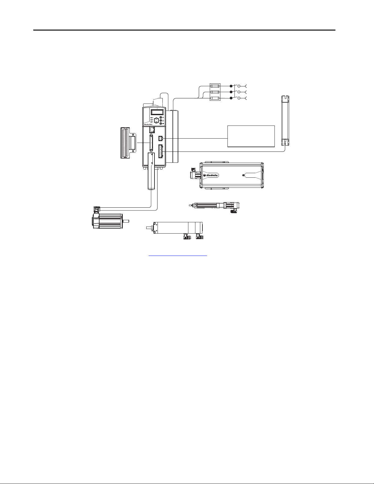
Figure 1 - Typical Kinetix 350 Drive Installation
2097-V3xxxx-LM
Kinetix 350 Drive
2097-Fx
AC Line Filter (optional equipment)
2097-F1 Filter Shown
Line
Disconnect
Device
Input
Fusin g
Three-phase
Input Power
24V DC Control Back-up
Power Supply
(optional equipment)
MP-Series and TL-Series
Rotary Motors
(MPL-Bxxxx motors shown)
Bulletin 2090
Motor Feedback Cables
Bulletin 2090
Motor Power Cables
2097-TB1 Terminal
Expansion Block
2097-Rx
Shunt Resistor
(optional equipment)
MP-Series and TL-Series Electric Cylinders
(MPAR-Bxxxx electric cylinders shown)
MP-Series Integrated Linear Stages
(MPAS-B9xxx ballscrew shown)
MP-Series Heavy-duty Electric Cylinders
(MPAI-Bxxxx electric cylinders shown)
2090-K2CK-D15M
Low-profile Connector Kit
Start Chapter 1
(1) See Ethernet Cable Connections on page 74 for information on how to use an unmanaged switch in your application.
Rockwell Automation Publication 2097-UM002D-EN-P - April 2017 13
Page 14
Chapter 1 Start
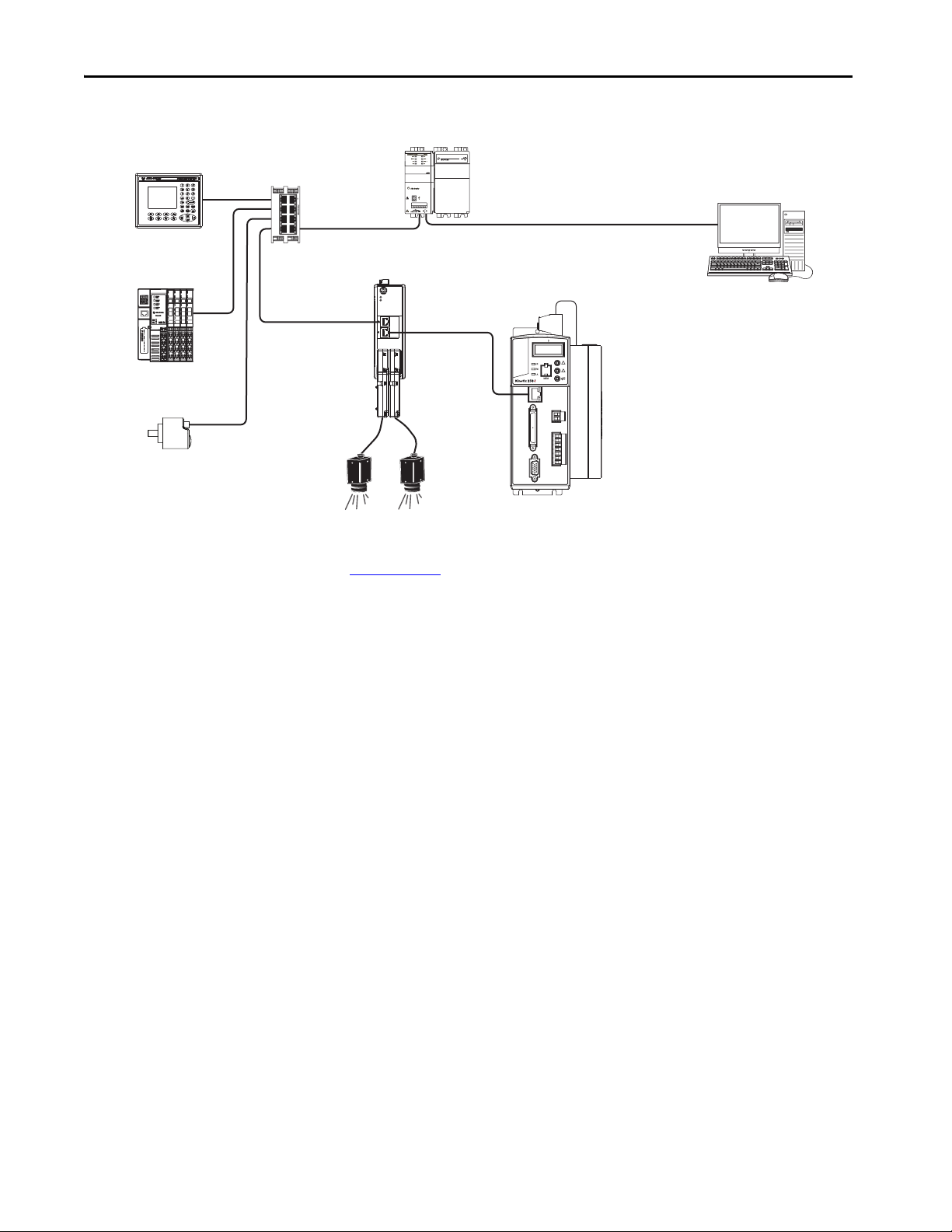
2097-V3xxxx-LM
Kinetix 350 Drive
1783-US08T
Stratix® 2000 Switch
Compac tLogix™ Co ntroller System
1769-L33ERM Shown
1585J-M8CBJM-x (shielded) or
11585J-M8UBJM-x (high-flex shielded)
Ethernet Cable
RSLogix 5000® Software
(version 20.00.00 or later) or the
Studio 5000 Logix Designer® Application
PanelView ™ Plus Co mpact
Display Terminal
1734-AENT POINT I/O™
EtherNet/IP Adapter
2198-ABQE
Encoder Output Module
Line Scan
Cameras
842E-CM Integrated Motion
Encoder on EtherNet/IP
Figure 2 - Typical K350 Communication Configuration
P
W
R
1
2
3
4
5
6
7
8
MOD
NET
OUTPUT-A OUTPUT-B
See Encoder Output Module Installation Instructions, publication
2198-UM003
. For information to help you install and wire the 2198-ABQE
Encoder Output Module.
14 Rockwell Automation Publication 2097-UM002D-EN-P - April 2017
Page 15

Start Chapter 1
Catalog Number Explanation
Kinetix 350 drive catalog numbers and descriptions are listed in these tables.
Table 3 - Kinetix 350 Drives (single-phase)
Cat. No. Input Voltage
2097-V31PR0-LM
2097-V31PR2-LM 5.7
2097-V32PR0-LM
2097-V32PR2-LM 5.7
2097-V32PR4-LM 11.3
120V, 1 Ø
240V, 1 Ø
240V, 1 Ø
Table 4 - Kinetix 350 Drives (single/three-phase)
Cat. No. Input Voltage
2097-V33PR1-LM
2097-V33PR3-LM 5.7
2097-V33PR5-LM 11.3
2097-V33PR6-LM 17.0
120V, 1 Ø
240V, 1 Ø
240V, 3 Ø
Table 5 - Kinetix 350 Drives (three-phase)
Continuous Output
Current A (0-pk)
2.8
2.8
Continuous Output
Current A (0-pk)
2.8
Featu res
•120V Doubler mode
•Safe Torque-off
• Integrated AC line filter
•Safe Torque-off
Featu res
Safe Torque-off
Cat. No. Input Voltage
2097-V34PR3-LM
480V, 3 Ø
2097-V34PR6-LM 8.5
Table 6 - Kinetix 350 Drive Accessories
Cat. No. Drive Components
2097-Fx AC line filters
2097-TB1 Terminal block for I/O connector
2097-Rx Shunt resistors
2097-PGMR Memory module programmer
2097-MEM Memory modules 12 pack
Continuous Output
Current A (0-pk)
2.8
Featu res
Safe Torque-off2097-V34PR5-LM 5.7
Rockwell Automation Publication 2097-UM002D-EN-P - April 2017 15
Page 16

Chapter 1 Start
Agency Compliance
If this product is installed within the European Union and has the CE
marking, the following regulations apply.
ATT EN TI ON : Meeting CE requires a grounded system. The method of
grounding the AC line filter and drive must match. Failure to do this renders
the filter ineffective and can cause damage to the filter.
For grounding examples, see Grounding Your Kinetix 350 Drive System
page 58
.
For more information on electrical noise reduction, see the System Design for
Control of Electrical Noise Reference Manual, publication GMC-RM001
on
.
CE Requirements
To meet CE requirements, these requirements apply:
• Install an AC line filter (Bulletin 2090 or 2097) as close to the drive as
possible.
• Use 2090 series motor power cables or use connector kits and terminate
the cable shields to the subpanel with clamp provided.
• Use 2090 series motor feedback cables or use connector kits and
properly terminate the feedback cable shield. Drive-to-motor power and
feedback cables must not exceed 20 m (65.6 ft).
• Install the Kinetix 350 system inside an enclosure. Run input power
wiring in conduit (grounded to the enclosure) outside of the enclosure.
Separate signal and power cables.
• Segregate input power wiring and motor power cables from control
wiring and motor feedback cables. Use shielded cable for power wiring
and provide a grounded 360° clamp termination.
See Appendix A on page 129
wiring and drive/motor interconnect diagrams.
16 Rockwell Automation Publication 2097-UM002D-EN-P - April 2017
for interconnect diagrams, including input power
Page 17
Chapter 2
Install the Kinetix 350 Drive System
Top ic Pa ge
System Design Guidelines 17
Electrical Noise Reduction 24
Mount Your Kinetix 350 Drive 32
ATT EN TI ON : Plan the installation of your system so that you can cut, drill,
tap, and weld with the system that is removed from the enclosure. Because
the system is of the open type construction, be careful to keep any metal
debris from falling into it. Metal debris or other foreign matter can become
lodged in the circuitry, which can result in damage to components.
System Design Guidelines
Use the information in this section when designing your enclosure and
planning to mount your system components on the panel.
For on-line product selection and system configuration tools, including
AutoCAD (DXF) drawings of the product, refer to
http://www.rockwellautomation.com/global/support/selection.page
System Mounting Requirements
• To comply with UL and CE requirements, the Kinetix® 350 system must
be enclosed in a grounded conductive enclosure. It must that offer
protection as defined in standard EN 60529 (IEC 529) to IP4X such
that they are not accessible to an operator or unskilled person. A NEMA
4X enclosure exceeds these requirements providing protection to IP66.
• The panel that you install inside the enclosure for mounting your system
components must be on a flat, rigid, vertical surface that won’t be
subjected to shock, vibration, moisture, oil mist, dust, or corrosive
vapors.
• Size the drive enclosure so as not to exceed the maximum ambient
temperature rating. Consider heat dissipation specifications for all drive
components.
• Segregate input power wiring and motor power cables from control
wiring and motor feedback cables. Use shielded cable for power wiring
and provide a grounded 360° clamp termination.
Rockwell Automation Publication 2097-UM002D-EN-P - April 2017 17
Page 18

Chapter 2 Install the Kinetix 350 Drive System
• Use high-frequency (HF) bonding techniques to connect the enclosure,
machine frame, and motor housing, and to provide a low-impedance
return path for high-frequency (HF) energy and reduce electrical noise.
• Use 2090 series motor feedback cables or use connector kits and
properly terminate the feedback cable shield. Drive-to-motor power and
feedback cables must not exceed 20 m (65.6 ft).
IMPORTANT System performance was tested at these cable length specifications. These
limitations are also a CE requirement.
See the System Design for Control of Electrical Noise Reference Manual,
publication GMC-RM001
, to understand the concept of electrical noise
reduction better.
Circuit Breaker/Fuse Selection
The Kinetix 350 drives use internal solid-state motor short-circuit protection
and, when protected by suitable branch circuit protection, are rated for use on
a circuit capable of delivering up to 100,000 A (fuses) and 65,000 A (circuit
breakers).
IMPORTANT Do not use circuit protection devices on the output of an AC drive as an
isolating disconnect switch or motor overload device. These devices are
designed to operate on sine wave voltage and the drive's PWM waveform
does not allow it to operate properly. As a result, damage to the device
occurs.
Make sure the selected components are properly coordinated and meet
acceptable codes including any requirements for branch circuit protection.
Evaluation of the short-circuit available current is critical and must be kept
below the short-circuit current rating of the circuit breaker.
See the Kinetix Servo Drives Specifications Technical Data, publication
KNX-TD003
for input current and inrush current specifications for your
Kinetix 350 drive.
See Fuse and Circuit Breaker (CB) Specifications
on page 19 for
recommended circuit breakers and fuses.
18 Rockwell Automation Publication 2097-UM002D-EN-P - April 2017
Page 19

Install the Kinetix 350 Drive System Chapter 2
Table 7 - Fuse and Circuit Breaker (CB) Specifications
UL Applications IEC (non-UL) Applications
Drive Cat. No.
2097-V31PR0-LM
Drive
Voltage
120V
Phase
Single-phase
(voltage doubler)
Fuses
(Bussmann)
Cat. No.
Miniature CB
Cat. No.
KTK-R-20 (20 A) 14 89-M1C200 140M-D8E-C20 1489-M1C200 1492-SPM1D200 140M-D8E-C20
120/240V Single-phase KTK-R-10 (10 A) 1489-M1C100 140M-C2E-C10 1489-M1C100 1492-SPM1D100 140M-C2E-C10
Single-phase
(voltage doubler)
KTK-R-30 (30 A) 14 89-M1C300 140M-F8E-C32 1489-M1C300 1492-SPM1D300 140M-F8E-C32
2097-V31PR2-LM
120V
120/240V Single-phase KTK-R-20 (20 A) 1489-M1C200 140M-D8E-C20 1489-M1C200 1492-SPM1D200 140M-D8E-C20
2097-V32PR0-LM
2097-V32PR2-LM KTK-R-20 (20 A) 1489-M1C200 140M-D8E-C20 1489-M1C200 1492-SPM1D200 140M-D8E-C20
240V Single-phase
KTK-R-20 (20 A) 14 89-M1C150 140M-D8E-C16 1489-M1C150 1492-SPM1D150 140M-D8E-C16
2097-V32PR4-LM KTK-R-30 (30 A) 1489-M1C300 140M-F8E-C32 1489-M1C300 1492-SPM1D320 140M-F8E-C32
2097-V33PR1-LM
2097-V33PR3-LM
2097-V33PR5-LM
2097-V33PR6-LM
120/240V Single-phase KTK-R-20 (20 A) 1489-M1C200 140M-D8E-C20 1489-M1C200 1492-SPM1D200 140M-D8E-C20
240V Three-phase KTK-R-15 (15 A) 1489-M3C150 140M-D8E-C16 1489-M3C150 1492-SPM3D150 140M-D8E-C16
120/240V Single-phase KTK-R-20 (20 A) 1489-M1C200 140M-D8E-C20 1489-M1C200 1492-SPM1D200 140M-D8E-C20
240V Three-phase KTK-R-15 (15 A) 1489-M3C150 140M-D8E-C16 1489-M3C150 1492-SPM3D150 140M-D8E-C16
120/240V Single-phase KTK-R-30 (30 A) 1489-M1C300 140M-F8E-C32 1489-M1C300 1492-SPM1D300 140M-F8E-C32
240V Three-phase KTK-R-20 (20 A) 1489-M3C200 140M-D8E-C20 1489-M3C200 1492-SPM3D200 140M-D8E-C20
120/240V Single-phase
LPJ-40SP (40 A)
Class J
N/A
240V Three-phase KTK-R-30 (30 A) 1489-M3C300 1489-M3C300 1492-SPM3D300
2097-V34PR3-LM
2097-V34PR5-LM KTK-R-10 (10 A) 1489-M3C100 140M-C2E-C10 1489-M3C100 1492-SPM3D100 140M-C2E-C10
480V Three-phase
KTK-R-10 (10 A) 14 89-M3C100 140M-C2E-C10 1489-M3C100 1492-SPM3D100 140M- C2E-C10
2097-V34PR6-LM KTK-R-20 (20 A) 1489-M3C200 140M-D8E-C20 1489-M3C200 1492-SPM3D200 140M-D8E-C20
(1) Bulletin 1492 and 1489 circuit protection devices have lower short-circuit current ratings than Bulletin 140M devices.
See http://ab.rockwellautomation.com/allenbradley/productdirectory.page?
for product literature with specific short-circuit ratings.
(2) For UL applications, Bulletin 140M devices are applied as self-protected combination motor controllers.
Motor
(1)
Protection CB,
Self-protected CMC
Cat. No.
140M-F8E-C32
(1) (2)
Miniature CB
Cat. No.
N/A N/A
(1)
Motor Protection CB
Cat. No.
140M-F8E-C32
(1)
Rockwell Automation Publication 2097-UM002D-EN-P - April 2017 19
Page 20

Chapter 2 Install the Kinetix 350 Drive System
Contactor Ratings
Table 8 - Kinetix 350 Drives (120/240V)
Cat. No.
2097-V31PR0-LM
2097-V31PR2-LM
Drive
Volt age
120V 100-C23x10 100-C23Zx10
240V 100-C12x10 100-C12Zx10
120V 100-C30x10 100-C30Zx10
240V 100-C23x10 100-C23Zx10
AC Coil Contactor DC Coil Contactor
Table 9 - Kinetix 350 Drives (240V)
Cat. No.
2097-V32PR0-LM 240V 100-C23x10 100-C23Zx10
2097-V32PR2-LM 240V 100-C23x10 100-C23Zx10
2097-V32PR4-LM 240V 100-C30x10 100-C30Zx10
2097-V33PR1-LM
2097-V33PR3-LM
2097-V33PR5-LM
2097-V33PR6-LM
Drive
Volt age
120V 100-C23x10 100-C23Zx10
240V 100-C16x10 100-C16Zx10
120V 100-C23x10 100-C23Zx10
240V 100-C16x10 100-C16Zx10
120V 100-C30x10 100-C30Zx10
240V 100-C23x10 100-C23Zx10
120V N/A N/A
240V 100-C30x10 100-C30Zx10
AC Coil Contactor DC Coil Contactor
Table 10 - Kinetix 350 Drives (480V)
Cat. No.
2097-V34PR3-LM
2097-V34PR5-LM 100-C12x10 100-C12Zx10
2097-V34PR6-LM 100-C23x10 100-C23Zx10
Drive
Volt age
480V
AC Coil Contactor DC Coil Contactor
100-C12x10 100-C12Zx10
Transformer Selection
The Kinetix 350 drive does not require an isolation transformer for threephase input power. However, a transformer can be required to match the
voltage requirements of the controller to the available service.
To choose the size of a transformer for the main AC power inputs, refer to on
page 18
and Transformer Specifications for Input Power on page 21.
IMPORTANT If you are using an autotransformer, make sure that the phase to neutral/
ground voltages do not exceed the input voltage ratings of the drive.
20 Rockwell Automation Publication 2097-UM002D-EN-P - April 2017
Page 21

Install the Kinetix 350 Drive System Chapter 2
A =
0.38Q
1.8T - 1.1
A =
0.38 (416)
1.8 (20) - 1.1
= 4.53 m
2
IMPORTANT Use a form factor of 1.5 for single and three-phase power (where form factor
is used to compensate for transformer, drive, and motor losses, and to
account for utilization in the intermittent operating area of the torque speed
curve).
For example, to choose the size of a transformer for the voltage
requirements of catalog number
2097-V34PR6-LM = 3 kW continuous x 1.5 = 4.5 KVA transformer.
Transformer Specifications for Input Power
Attribute Value (460V system)
Input volt-amperes 750VA
Input voltage 480V AC
Output voltage 120…240V AC
Enclosure Selection
This example is provided to assist you in choosing the size of the enclosure for
your Bulletin 2097 drive system. You need heat dissipation data from all
components that are planned for your enclosure to calculate the enclosure size.
See Power Dissipation Specifications on page 22
for your drive.
With no active method of heat dissipation (such as fans or air conditioning),
either of the following approximate equations can be used.
Metric Standard English
4.08Q
A =
T - 1.1
Where T is temperature difference between inside air
and outside ambient (°C), Q is heat that is generated in
enclosure (Watts), and A is enclosure surface area (m²).
The exterior surface of all six sides of an enclosure is
calculated as
A = 2dw + 2dh + 2wh A = (2dw + 2dh + 2wh) /144
Where d (depth), w (width), and h (height) are in
meters.
Where T is temperature difference between inside air
and outside ambient (°F), Q is heat that is generated in
enclosure (Watts), and A is enclosure surface area (ft
The exterior surface of all six sides of an enclosure is
calculated as
Where d (depth), w (width), and h (height) are in
inches.
2)
.
If the maximum ambient rating of the Kinetix 350 drive system is 40 °C
(104 °F) and if the maximum environmental temperature is 20 °C (68 °F), then
T=20. In this example, the total heat dissipation is 416 W (sum of all
components in enclosure). So, in the equation below, T=20 and Q=416.
Rockwell Automation Publication 2097-UM002D-EN-P - April 2017 21
Page 22

Chapter 2 Install the Kinetix 350 Drive System
In this example, the enclosure must have an exterior surface of at least 4.53 m.
If any portion of the enclosure is not able to transfer heat, exclude heat in the
calculation.
Because the minimum cabinet depth to house the Kinetix 350 system (selected
for this example) is 332 mm (13 in.), the cabinet must be approximately 2000 x
700 x 332 mm (78.7 x 27.6 x 13.0 in.) HxWxD.
2 x (0.332 x 0.70) + 2 x (0.332 x 2.0) + 2 x (0.70 x 2.0) = 4.59 m²
Because this cabinet size is considerably larger than what is necessary to house
the system components, it can be more efficient to provide a means of cooling
in a smaller cabinet. Contact your cabinet manufacturer for options available to
cool your cabinet.
Power Dissipation Specifications
This table shows the maximum power dissipation of each drive. Use this table
to size an enclosure and calculate required ventilation for your Kinetix 350
drive system.
Cat. No. Power Dissipation, W
2097-V31PR0-LM 28
2097-V31PR2-LM 39
2097-V32PR0-LM 28
2097-V32PR2-LM 39
2097-V32PR4-LM 67
2097-V33PR1-LM 28
2097-V33PR3-LM 39
2097-V33PR5-LM 67
2097-V33PR6-LM 117
2097-V34PR3-LM 39
2097-V34PR5-LM 58
2097-V34PR6-LM 99
22 Rockwell Automation Publication 2097-UM002D-EN-P - April 2017
Page 23
Install the Kinetix 350 Drive System Chapter 2
A
25.0 mm (1.0 in.) Clearance
for Airflow and Installation
3 mm (0.12 in.)
Side Clearance
3 mm (0.12 in.)
Side Clearance
25.0 mm (1.0 in.) Clearance
for Airflow and Installation
Drive
Cat. No.
A
2097-V31PR0-LM 185 (7.29)
2097-V31PR2-LM 185 (7.29)
2097-V32PR0-LM 230 (9.04)
2097-V32PR2-LM 230 (9.04)
2097-V32PR4-LM 230 (9.04)
2097-V33PR1-LM 185 (7.29)
2097-V33PR3-LM 185 (7.29)
2097-V33PR5-LM 185 (7.29)
2097-V33PR6-LM 230 (9.04)
2097-V34PR3-LM 185 (7.29)
2097-V34PR5-LM 185 (7.29)
2097-V34PR6-LM 230 (9.04)
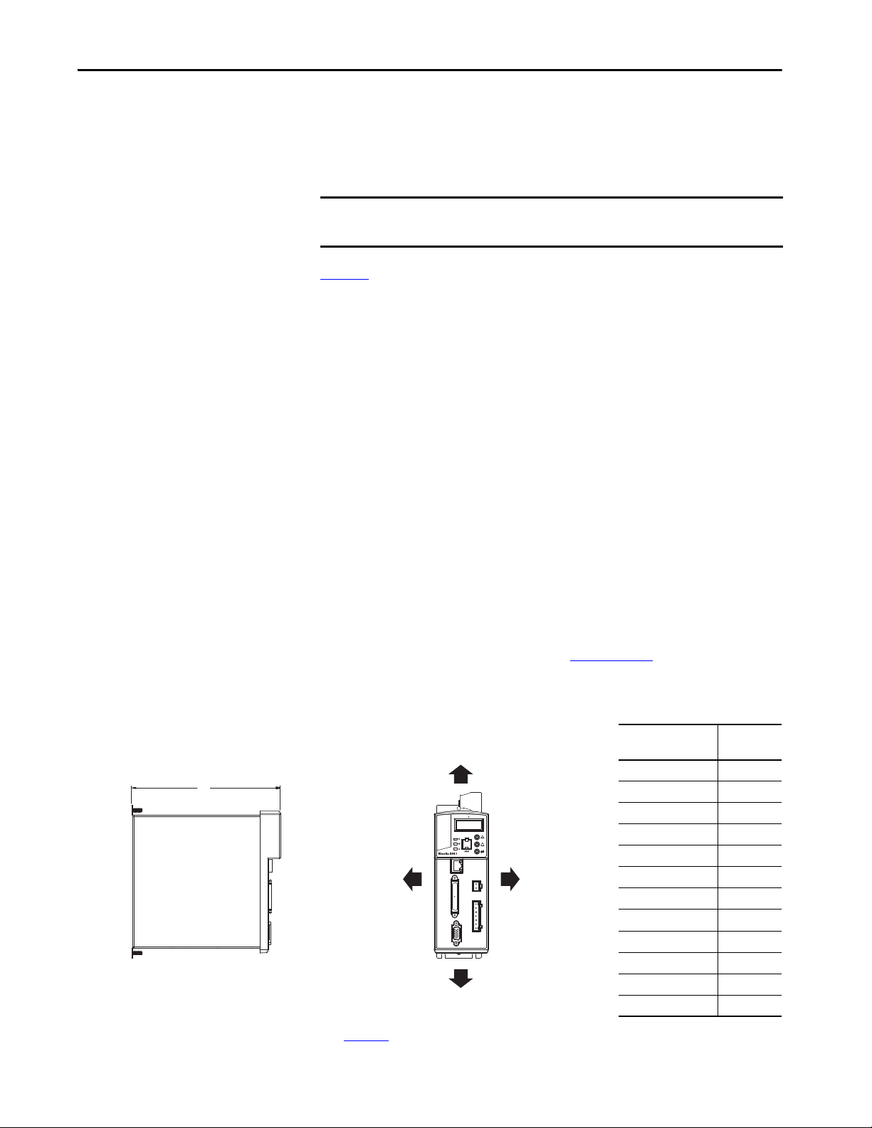
Minimum Clearance Requirements
This section provides information to help you choose the size of your cabinet
and the placement of your Kinetix 350 system components.
IMPORTANT Mount the module in an upright position as shown. Do not mount the drive
module on its side.
Figure 3
illustrates minimum clearance requirements for proper airflow and
installation:
• Additional clearance is required depending on the accessory items
installed.
• An additional 9.7 mm (0.38 in.) clearance is required left of the drive if
the I/O expansion terminal block is used.
• An additional 26 mm (1.0 in.) clearance is required right of the drive
when the heatsink is present.
• An additional 36 mm (1.42 in.) is required right of the drive when the
side-mount line filter is present. An additional 50 mm (2.0 in.) is
required behind the drive when the rear-mount line filter is present.
• An additional 5.0 mm (0.19 in.) clearance is required in front of the
drive when the 2090-K2CK-D15M feedback connector kit is used.
• Additional clearance is required for the cables and wires that are
connected to the top, front, and bottom of the drive.
• An additional 150 mm (6.0 in.) is required when the drive is mounted
next to noise sensitive equipment or clean wireways.
See Kinetix 350 Drive Power Specifications in Kinetix Servo Drives
Specifications Technical Data, publication KNX-TD003
for Kinetix 350 drive
dimensions.
Figure 3 - Minimum Clearance Requirements
See page 22 for power dissipation specifications.
Rockwell Automation Publication 2097-UM002D-EN-P - April 2017 23
Page 24

Chapter 2 Install the Kinetix 350 Drive System
Electrical Noise Reduction
This section outlines practices that minimize the possibility of noise-related
failures as they apply specifically to Kinetix 350 system installations. For more
information on the concept of high-frequency (HF) bonding, the ground
plane principle, and electrical noise reduction, refer to the System Design for
Control of Electrical Noise Reference Manual, publication GMC-RM001
.
Bonding Drives
Bonding is the practice where you connect metal chassis, assemblies, frames,
shields, and enclosures to reduce the effects of electromagnetic interference
(EMI).
Unless specified, most paints are not conductive and act as insulators. To
achieve a good bond between drive and the subpanel, surfaces must be paintfree or plated. Bonded metal surfaces create a low-impedance return path for
high-frequency energy.
IMPORTANT To improve the bond between the drive and subpanel, construct your
subpanel out of zinc plated (paint-free) steel.
Improper bonding of metal surfaces blocks the direct return path and lets highfrequency energy travel elsewhere in the cabinet. Excessive high-frequency
energy can affect the operation of other microprocessor controlled equipment.
24 Rockwell Automation Publication 2097-UM002D-EN-P - April 2017
Page 25
Install the Kinetix 350 Drive System Chapter 2
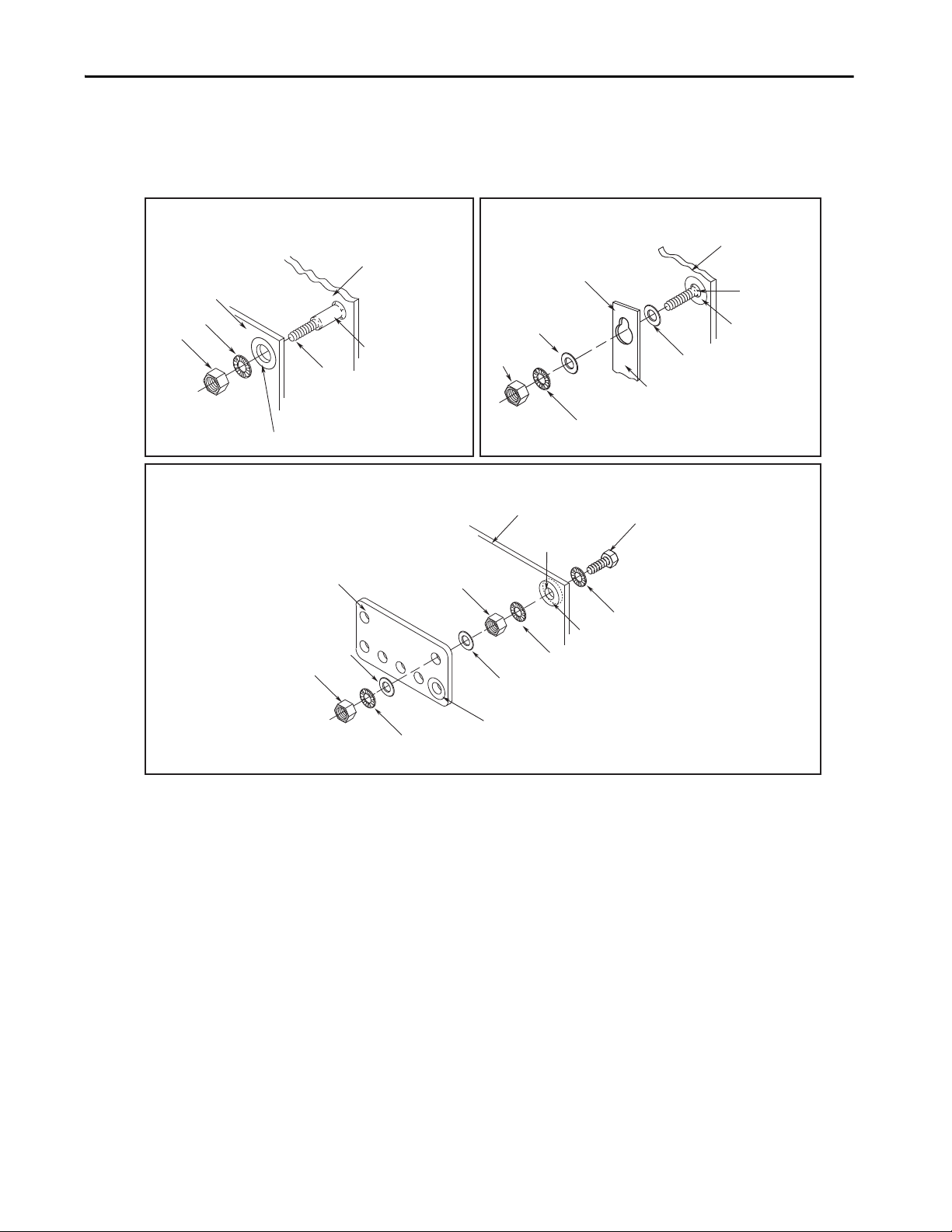
Stud-mounting the Subpanel
to the Enclosure Back Wall
Subpanel
Star Washer
Nut
Back Wall of
Enclosure
Weld ed St ud
Use a wire brush to remove paint from
threads to maximize ground connection.
Use plated panels or scrape paint on
front of panel.
Nut
Star Washer
Welded Stud
Flat Washer
Stud-mounting a Ground Bus
or Chassis to the Subpanel
Scrape Paint
Flat Washer
If the mounting bracket is coated with
a non-conductive material (anodized
or painted), scrape the material around
the mounting hole.
Mounting Bracket or
Ground Bus
Subpanel
Subpanel
Nut
Nut
Star Washer
Flat Washer
Star Washer
Star Washer
Scrape paint on both sides of
panel and use star washers.
Tapped Hole
Bolt
Flat Washer
Ground Bus or
Mounting Bracket
If the mounting bracket is coated with
a non-conductive material (anodized
or painted), scrape the material around
the mounting hole.
Bolt-mounting a Ground Bus or Chassis to the Back Panel
These illustrations show recommended bonding practices for painted panels,
enclosures, and mounting brackets.
Figure 4 - Recommended Bonding Practices for Painted Panels
Rockwell Automation Publication 2097-UM002D-EN-P - April 2017 25
Page 26
Chapter 2 Install the Kinetix 350 Drive System
Wire B raid
25.4 mm (1.0 in.) by
6.35 mm (0.25 in.)
Remove paint
from cabinet.
Ground bus
that is bonded
to the
subpanel.
Wire Br aid
25.4 mm (1.0 in.) by
6.35 mm (0.25 in.)
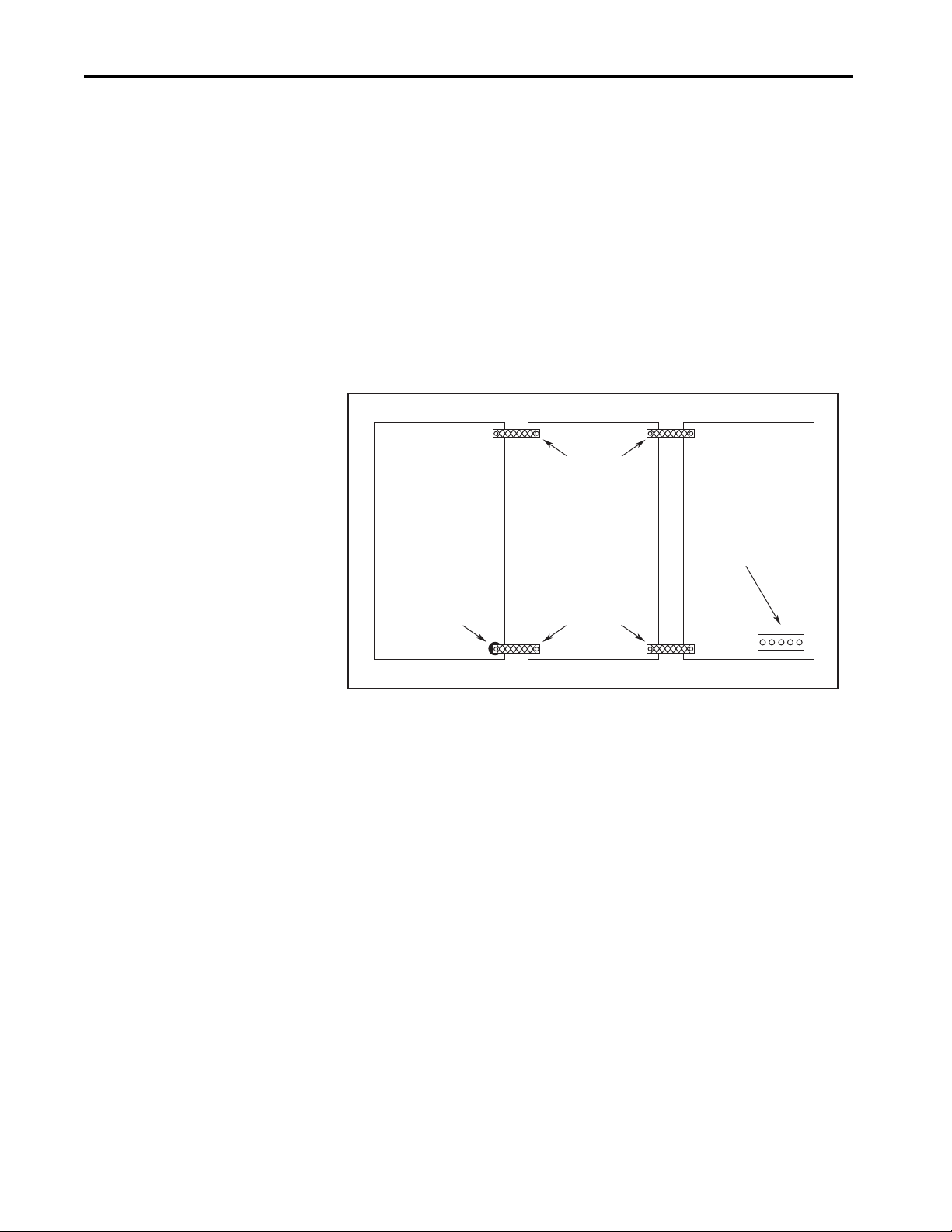
Bonding Multiple Subpanels
Bonding multiple subpanels creates a common low-impedance exit path for the
high frequency energy inside the cabinet. Subpanels that are not bonded
together cannot share a common low impedance path. This difference in
impedance can affect networks and other devices that span multiple panels:
• Bond the top and bottom of each subpanel to the cabinet by using
25.4 mm (1.0 in.) by 6.35 mm (0.25 in.) wire braid. As a rule, the wider
and shorter the braid is, the better the bond.
• Scrape the paint from around each fastener to maximize metal-to-metal
contact.
Figure 5 - Multiple Subpanels and Cabinet Recommendations
26 Rockwell Automation Publication 2097-UM002D-EN-P - April 2017
Page 27
Install the Kinetix 350 Drive System Chapter 2
Clean Wireway
24V Motor
Brake PS
Circuit
Breaker
Contactors
Kinetix 350
Drive
I/O
(1)
, Ethernet, and
Feedback Cables
Very Dirty Zone
Segregated (not in wireway)
Route 24V DC I/O
Shielded Cable
Ethernet
(shielded)
Cable
I/O
(1)
, Motor Power, and Safety Cables
(4)
(3)
Dirty Wireway
XFMR
DC
Filter
Bulletin 2090
AC Line Filte r
(optional)
Route encoder/analog/registration
shielded cables.
DD
VD
VD
D
C
C
No sensitive
equipment within
150 mm (6.0 in.).
(2)
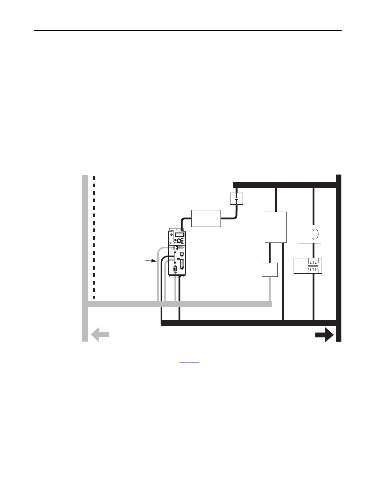
Establish Noise Zones
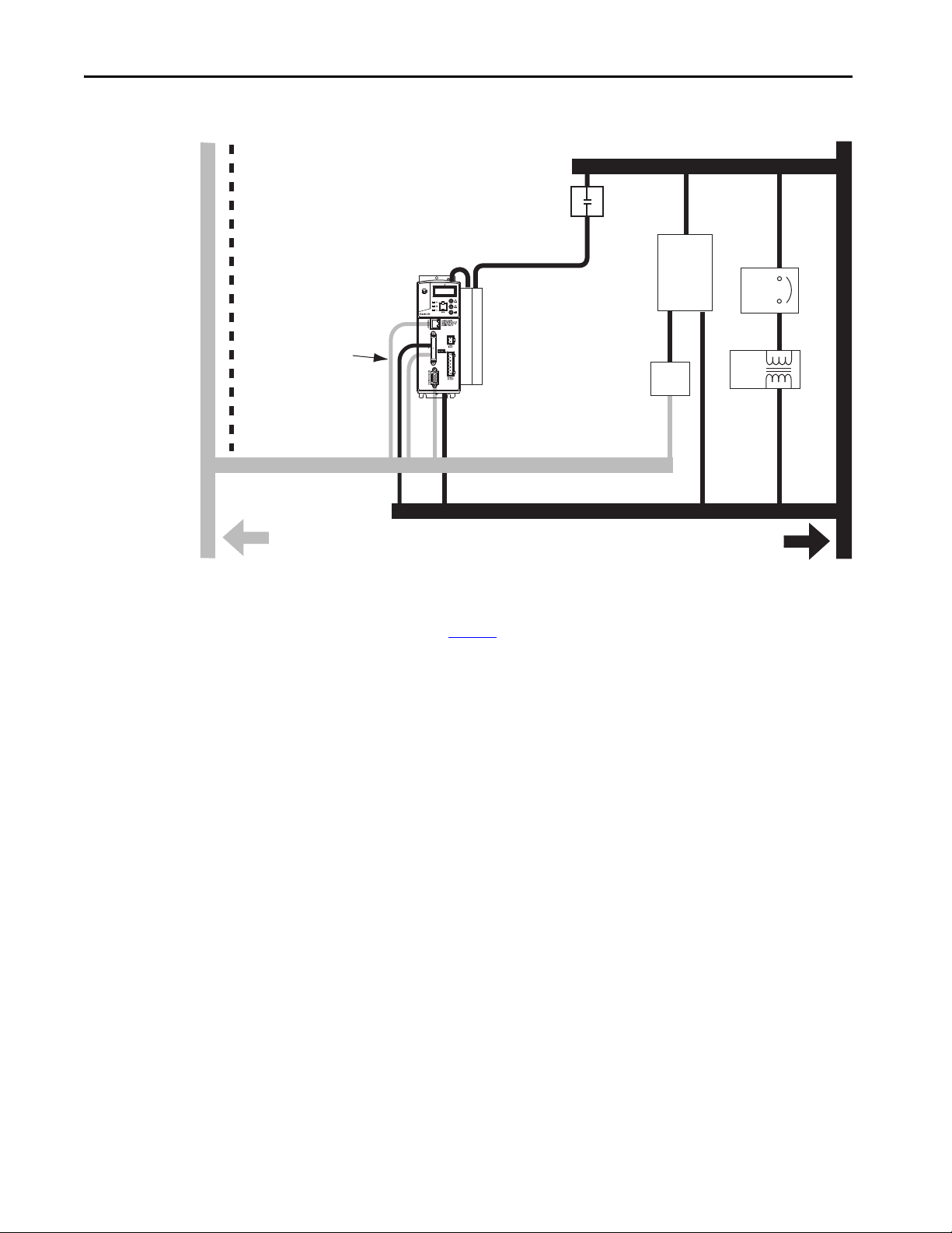
Observe these guidelines when individual input power components are used in
the Kinetix 350 system:
• The clean zone (C) exits left of the Kinetix 350 system and includes the
I/O wiring, feedback cable, Ethernet cable, and DC filter (gray
wireway).
• The dirty zone (D) exits right of the Kinetix 350 system (black wireway)
and includes the circuit breakers, transformer, 24V DC power supply,
contactors, AC line filter, motor power, and safety cables.
• The very dirty zone (VD) is limited to where the AC line (EMC) filter
VAC output jumpers over to the drive. Shielded cable is required only if
the very dirty cables enter a wireway.
Figure 6 - Noise Zones (Bulletin 2090 AC line filters)
(1) If drive system I/O cable contains (dirty) relay wires, route cable in dirty wireway.
(2) For tight spaces, use a grounded steel shield. For examples, refer to the System Design for Control of Electrical Noise Reference
Manual, publication GMC-RM001
(3) This voltage is a clean 24V DC available for any device that requires it. The 24V enters the clean wireway and exits to the left.
(4) This voltage is a dirty 24V DC available for motor brakes and contactors. The 24V enters the dirty wireway and exits to the right.
.
Rockwell Automation Publication 2097-UM002D-EN-P - April 2017 27
Page 28
Chapter 2 Install the Kinetix 350 Drive System
Clean Wireway
24V Motor
Brake PS
Circuit
Breaker
Contac tors
Kinetix 350
Drive
I/O
(1)
, Ethernet, and Feedback Cables
Very Dirty Zone
Segregated (not in wireway)
Route 24V DC I/O
Shielded Cable
Ethernet
(shielded)
Cable
I/O
(1)
, Motor Power, and S afety Cables
(4)
(3)
Dirty Wireway
XFMR
DC
Filter
Route encoder/analog/registration
shielded cables.
D
D
VD
VD
D
C
C
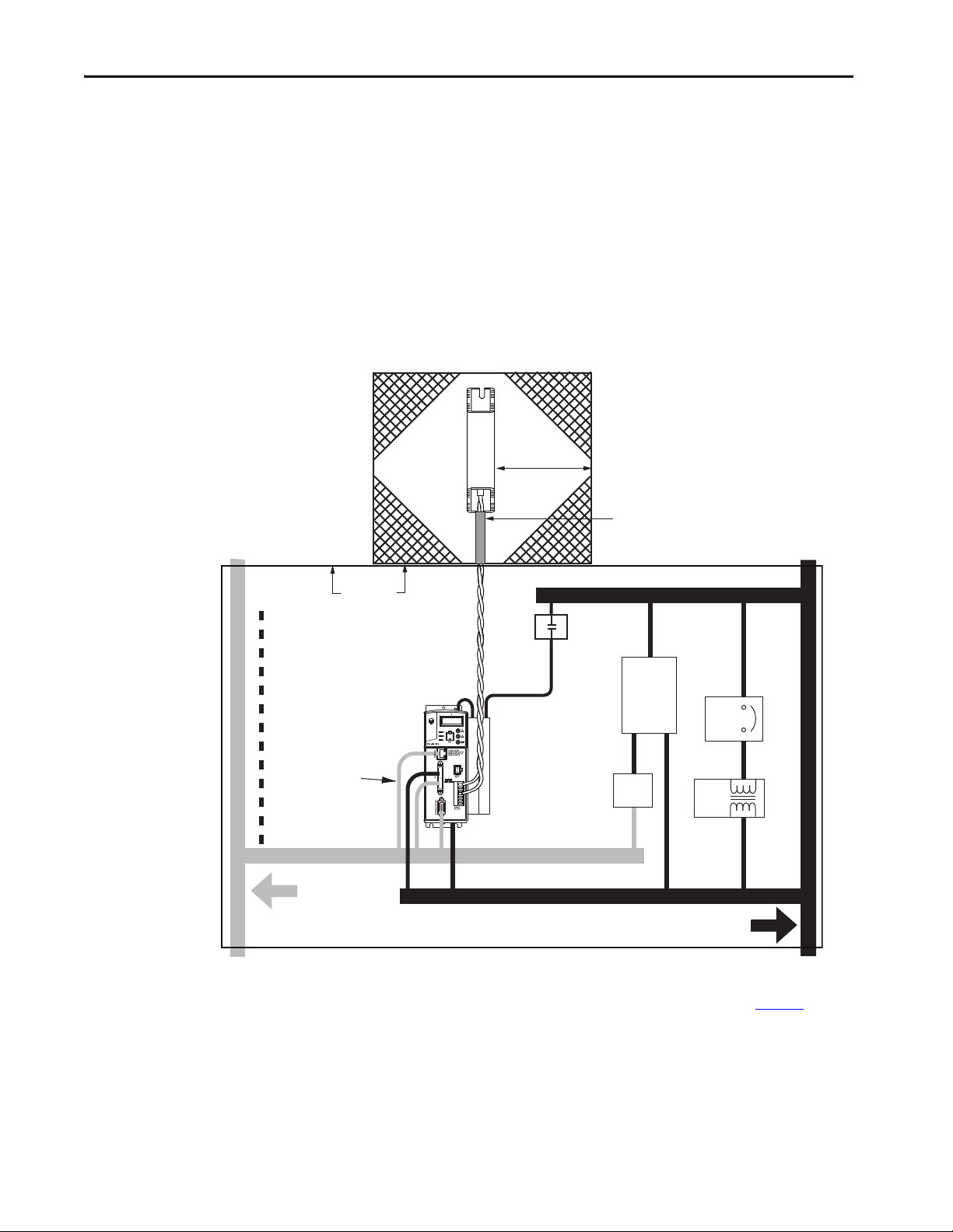
Bulletin 2097 AC line
filters mount to side,
as shown, or behind
the drive.
No sensitive
equipment within
150 mm (6.0 in.).
(2)
Figure 7 - Noise Zones (Bulletin 2097 AC line filters)
(1) If drive system I/O cable contains (dirty) relay wires, route cable in dirty wireway.
(2) For tight spaces, use a grounded steel shield. For examples, refer to the System Design for Control of Electrical Noise Reference
Manual, publication GMC-RM001
(3) This voltage is a clean 24V DC available for any device that requires it. The 24V enters the clean wireway and exits to the left.
(4) This voltage is a dirty 24V DC available for motor brakes and contactors. The 24V enters the dirty wireway and exits to the right.
.
28 Rockwell Automation Publication 2097-UM002D-EN-P - April 2017
Page 29

Install the Kinetix 350 Drive System Chapter 2
Cable Categories for Kinetix 350 Drive Components
This table indicates the zoning requirements of cables that are connected to the
Kinetix 350 drive components.
Table 11 - Kinetix 350 Drive Components
Zone Method
Wire/Cable Connector
L1, L2, L3 (unshielded cable) IPD X
U, V, W ( motor power) MP X X
B+-, B-, BR (shunt resistor) BC X
24V DC BP X
Control COM, 24V DC control, safety enable, and
feedback signals for safe-off feature
Motor feedback MF X X
Registration
Others X
Ethernet Port 1 X X
STO X
IOD
Very
Dirty
Dirty Clean
XX
Ferrite
Sleeve
Shielded
Cable
Noise Reduction Guidelines for Drive Accessories
See this section when mounting an AC line filter or shunt resistor module for
guidelines that are designed to reduce system failures that excessive electrical
noises cause.
AC Line Filters
If you are using a Bulletin 2090 line filter, mount the filter on the same panel as
the Kinetix 350 drive, and as close to the drive as possible.
Observe these guidelines when mounting your AC line filter:
• Good HF bonding to the panel is critical. For painted panels, refer to
the examples on page 24
• Segregate input and output wiring as far as possible.
.
Rockwell Automation Publication 2097-UM002D-EN-P - April 2017 29
Page 30
Chapter 2 Install the Kinetix 350 Drive System
Contactor
Dirty Wireway
Custom er-supp lied
Metal Enclosure
150 mm (6.0 in.)
clearance (min) on all four
sides of the shunt module.
Very dirty connections
segregated (not in wireway).
Shunt Wiring Methods:
Twisted pair in conduit (first choice).
Shielded twisted pair (second choice).
Twisted pair, two twists per foot (min) (third choice).
Metal Conduit
(where required
by local code)
Ethernet
(shielded)
Cable
No sensitive
equipment within
150 mm (6.0 in.).
(2)
Route 24V DC I/O
Shielded Cable
24V Motor
Brake PS
Enclosure
Clean Wireway
Circuit
Breaker
I/O
(1)
, Ethernet, and
Feedba ck Cables
DC
Filter
Kinetix 350 Drive
Route Encoder/Analog/Registration
Shielded Cables
D
VD
D
C
C
I/O
(1),
Motor Power and Safety Cables
XFMR
D
AC Line
Filter
VD
Shunt Resistors
Observe these guidelines when mounting your shunt resistor outside the
enclosure:
• Mount shunt resistor and wiring in the very dirty zone or in an external
shielded enclosure.
• Mount resistors in a shielded and ventilated enclosure outside the
cabinet.
• Keep unshielded wiring as short as possible. Keep shunt wiring as flat to
the cabinet as possible.
Figure 8 - Shunt Resistor Outside the Enclosure
(1) If drive system I/O cable contains (dirty) relay wires, route cable in dirty wire way.
(2) When space does not permit 150 mm (6.0 in.) clearance, install a grounded steel shield between the drive and clean wireway.
For examples, refer to the System Design for Control of Electrical Noise Reference Manual, publication GMC-RM001
.
30 Rockwell Automation Publication 2097-UM002D-EN-P - April 2017
Page 31

Install the Kinetix 350 Drive System Chapter 2
Shunt Wiring Methods:
Twisted pair in conduit (first choice).
Shielded twisted pair (second choice).
Twisted pair, two twists per foot (min) (third choice).
Contac tor
Dirty Wireway
Very dirty zone
segregated (not in wireway).
Ethernet
(shielded)
Cable
No sensitive
equipment within
150 mm (6.0 in.).
(2)
Route 24V DC I/O
Shielded Cable
24V Motor
Brake PS
Circuit
Breaker
I/O
(1)
, Ethernet, and Feedback
Cables
DC
Filter
Kinetix 350
Drive
Route Encoder/Analog/Registration
Shielded Cables
D
VD
C
I/O
(1)
, Motor Power, and Safety Cables
XFMR
D
D
AC Lin e
Filter
VD
D
C
Clean Wireway
Enclosure
When mounting your shunt module inside the enclosure, follow these
additional guidelines:
• Mount the shunt resistor anywhere in the dirty zone, but as close to the
Kinetix 350 drive as possible.
• Shunt wires can be run with motor power cables.
• Keep unshielded wiring as short as possible. Keep shunt wiring as flat to
the cabinet as possible.
• Separate shunt wires from other sensitive, low-voltage signal cables.
Figure 9 - Shunt Resistor inside the Enclosure
(1) If drive system I/O cable contains (dirty) relay wires, route cable in dirty wire way.
(2) When space does not permit 150 mm (6.0 in.) clearance, install a grounded steel shield between the drive and clean wireway.
For examples, refer to the System Design for Control of Electrical Noise Reference Manual, publication GMC-RM001
Motor Brake
The brake is mounted inside the motor and how you connect to the drive
depends on the motor series.
See Kinetix 350 Drive/Rotary Motor Wiring Examples
for the interconnect diagram of your drive/motor combination.
Rockwell Automation Publication 2097-UM002D-EN-P - April 2017 31
.
that begin on page 134
Page 32

Chapter 2 Install the Kinetix 350 Drive System
Mount Your Kinetix 350 Drive
This procedure assumes that you have prepared your panel and understand
how to bond your system. For installation instructions regarding other
equipment and accessories, refer to the instructions that came with those
products.
ATT EN TI ON : This drive contains electrostatic discharge (ESD) sensitive parts
and assemblies. You are required to follow static control precautions when
you install, test, service, or repair this assembly. If you do not follow ESD
control procedures, components can be damaged. If you are not familiar with
static control procedures, refer to Guarding Against Electrostatic Damage,
publication 8000-4.5.2
Follow these steps to mount your Kinetix 350 drive.
1. Lay out the position for the Kinetix 350 drive and accessories in the
enclosure.
See Establish Noise Zones
recommendations. Mounting hole dimensions for the Kinetix 350 drive
are shown in Kinetix Servo Drives Specifications Technical Data,
publication number KNX-TD003
2. Attach the Kinetix 350 drive to the cabinet, first by using the upper
mounting slots of the drive and then the lower.
, or any other applicable ESD Protection Handbook.
on page 27 for panel layout
.
The recommended mounting hardware is M4 (#6-32) steel machine
screws that are torqued to 1.1 N•m (9.8 lb•in). Observe bonding
techniques as described in Bonding Drives
IMPORTANT To improve the bond between the Kinetix 350 drive and subpanel,
construct your subpanel out of zinc plated (paint-free) steel.
3. Tighten all mounting fasteners.
on page 24.
32 Rockwell Automation Publication 2097-UM002D-EN-P - April 2017
Page 33

Chapter 3
Kinetix 350 Drive Connector Data
Top ic Pa ge
Kinetix 350 Drive Connectors and Indicators 34
Control Signal Specifications 39
Motor Feedback Specifications 44
Rockwell Automation Publication 2097-UM002D-EN-P - April 2017 33
Page 34
Chapter 3 Kinetix 350 Drive Connector Data
3
5 0
Kinetix® 350 Drive, Front View
(2097-V33PR5-LM drive is shown)
Kinetix 350 Drive, Bottom View
(2097-V33PR5-LM drive is shown)
Kinetix 350 Drive, Top View
(2097-V33PR5-LM drive is shown)
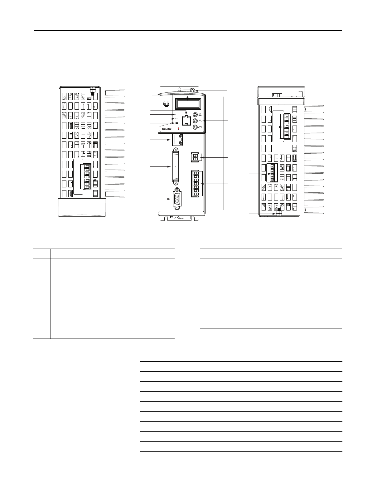
Kinetix 350 Drive Connectors and Indicators
Although the physical size of the Kinetix® 350 drives vary, the location of the
connectors and indicators is identical.
Figure 10 - Kinetix 350 Drive Connector and Indicators
2
3
4
5
6
7
8
1
9
0
10
13
14
12
15
11
10
Item Description Item Description
1 Mains (IPD) connector 9 Motor feedback (MF) connector
2 Data status indicator and diagnostic display 10 Ground lug
3 Memory module socket 11 Shunt resistor and DC bus (BC) connector
4 Network status indicator 12 Back-up power (BP) connector
5 Module status indicator 13 Display control push buttons (3)
6 Axis status indicator 14 Motor power (MP) connector
7 Ethernet communication port (Port 1) 15 Safe torque-off (STO) connector
8I/O (IOD) connector
Table 12 - Kinetix 350 Drive Connectors
Designator Description Connector
IPD AC input power 3-position or 4-position plug/header
PORT1 Ethernet communication port RJ45 Ethernet
IOD I/O SCSI 50-pin high-density connector
MF Motor feedback 15-pin high-density D-shell (male)
BP Back-up power 2-pin quick-connect terminal block
BC Shunt Resistor and DC Bus 7-pin quick-connect terminal block
MP Motor power 6-pin qui ck-connect te rminal block
STO Safe torque off (STO) Terminal 6-pin quick-connect terminal block
34 Rockwell Automation Publication 2097-UM002D-EN-P - April 2017
Page 35
Kinetix 350 Drive Connector Data Chapter 3
1 2 3 4 5 6
+24 V DC control
Control COM
Safety status
Safety input 1
Safety COM
Safety input 2
Bottom view of the Kinetix 350 drive.
(2097-V33PR5-LM drive is shown)
Wiring Plug Header
Safe Torque-off
(STO) Connector
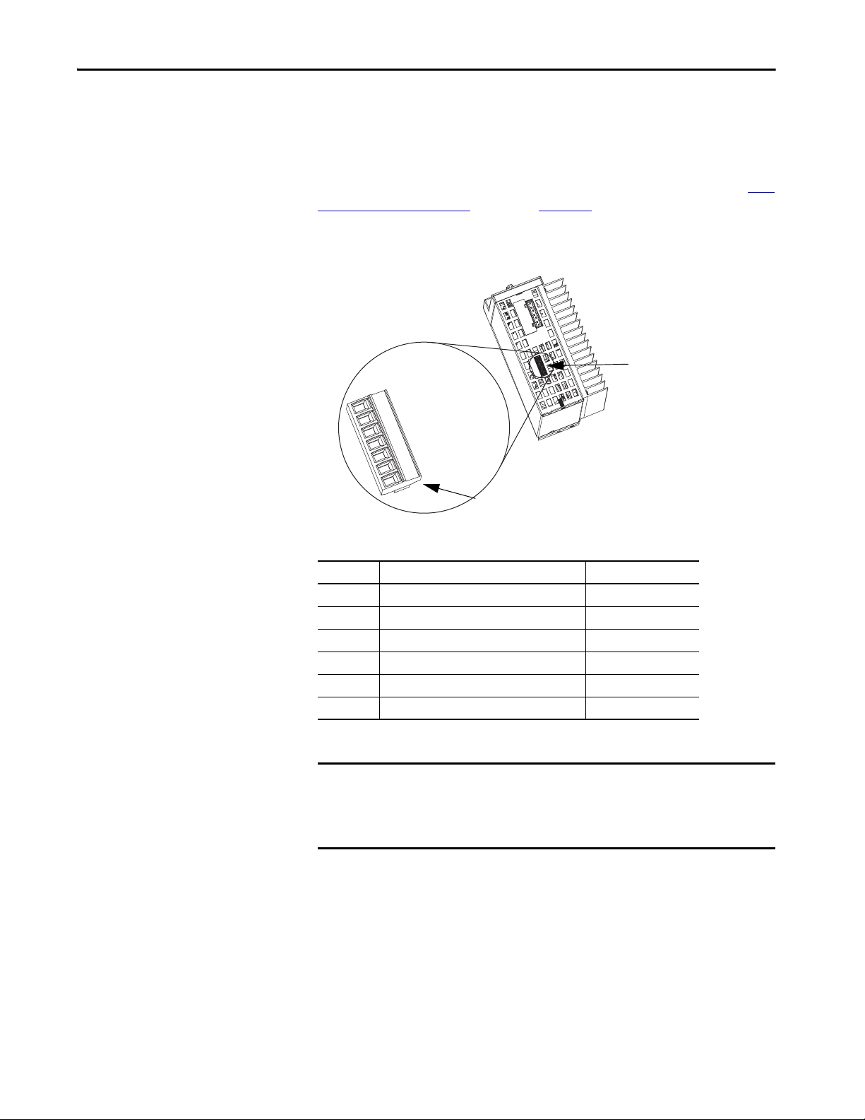
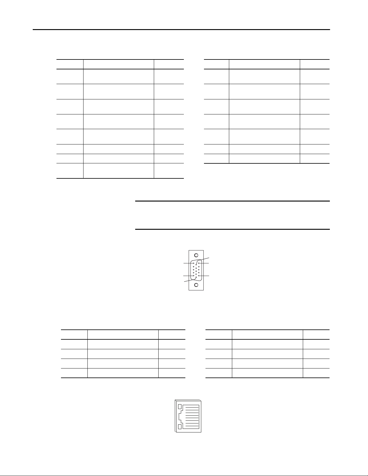
Safe Torque-off Connector Pinout
The Kinetix 350 drive ships with the (6-pin) wiring-plug header that connects
your safety circuit to the Kinetix 350 drive safe torque-off (STO) connector. If
your system does not use the safe torque-off feature, follow instructions in Safe
To r q u e- of f Fe atur e By p a ss starting on page 107 to wire the drive with motion-
allowed jumpers.
Figure 11 - Safe Torque-off Connector
Table 13 - Kinetix 350 Drive Safe Torque-off Connector Pinout
STO Pin Description Signal
1 +24V DC output from the drive +24V DC control
2 +24V DC output common Control COM
3 Safety status Safety Status
4 Safety input 1 (+24V DC to enable) Safety Input 1
5 Safety common Safety COM
6 Safety input 2 (+24V DC to enable) Safety Input 2
IMPORTANT Use only pins STO-1 (+24V DC Control) and STO-2 (Control COM) of the
motion-allowed jumpers to enable the drive when the safe torque-off
function is not used. When the safe torque-off function is in operation, the
24V supply must come from an external source.
Rockwell Automation Publication 2097-UM002D-EN-P - April 2017 35
Page 36

Chapter 3 Kinetix 350 Drive Connector Data
I/O Connector Pinout
IOD Pin Description Signal
1…25 Reserved Reserved
26 +/- Overtravel, enable, and home common COM
27 Negative hardware overtravel NEG_OT
28 Positive hardware overtravel POS_OT
29 Drive enable ENABLE
30 Home switch HOME_SW
31…35 Reserved —
36 Registration common REG_COM
37…38 Reserved —
39 Registration input REG
40…42 Reserved —
43 Motor brake release positive MTR_BRAKE+
44 Motor brake release negative MTR_BRAKE-
44…50 Reserved —
Figure 12 - Pin Orientation for 50-pin SCSI I/O (IOD) Connector
26
50
1
25
36 Rockwell Automation Publication 2097-UM002D-EN-P - April 2017
Page 37
Kinetix 350 Drive Connector Data Chapter 3
1
8
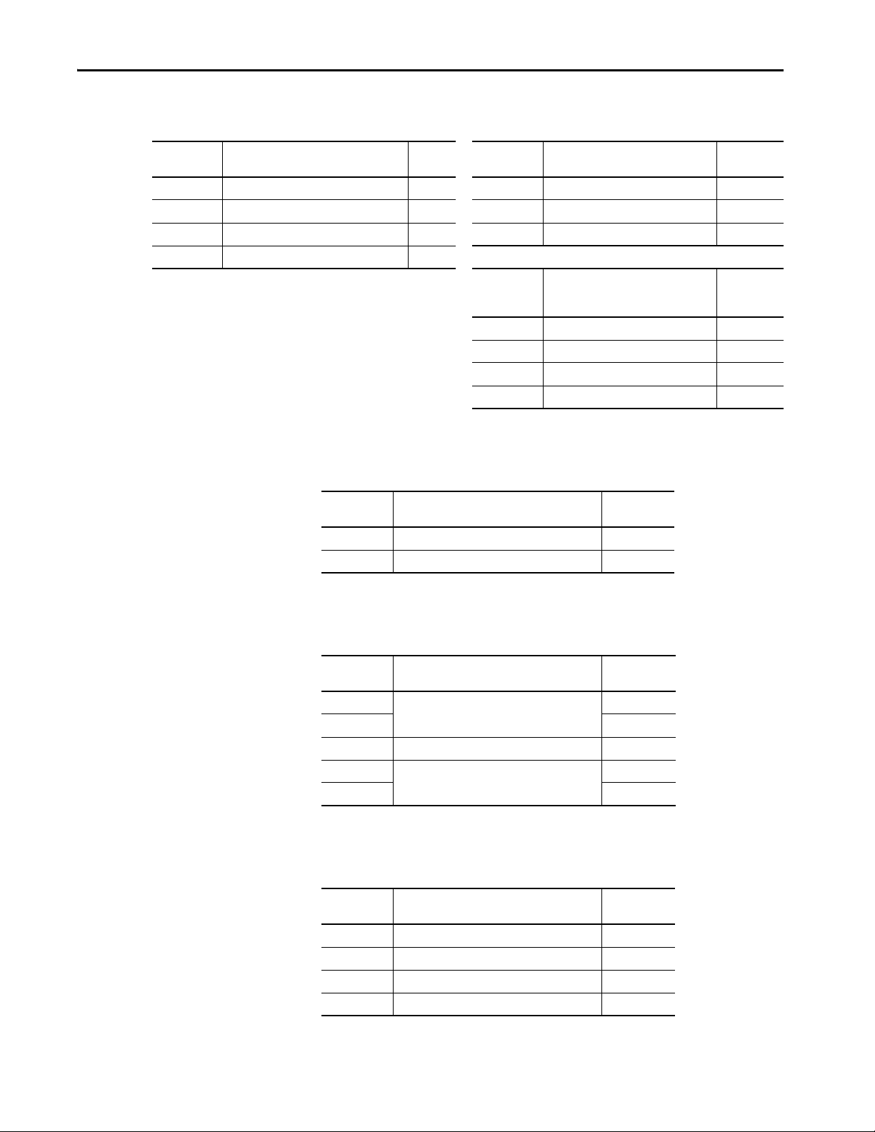
Motor Feedback (MF) Connector Pinout
MF Pin Description Signal MF Pin Description Signal
1
2
3
4
5
Sine differential input+
AM+ differential input+
Sine differential inputAM- differential input-
Cosine differential input+
BM+ differential input+
Cosine differential inputBM- differential input-
Data differential input +
Index pulse+
6 Common ECOM 14 Encoder power (+5V) EPWR_5V
7 Encoder power (+9V) EPWR_9V
8
(1) Not applicable unless motor has integrated thermal protection.
(2) Encoder power supply uses either 5V or 9V DC based on encoder/motor used.
Single-ended 5V Hall effect
commutation
SIN+
AM+
SINAM-
COS+
BM+
COSBM-
DATA+
IM+
S3
9
10
11
12
13
(2)
15 Reserved —
Reserved
Data differential input Index pulse-
Motor thermal switch
(normally closed)
(1)
Single-ended 5V Hall effect
commutation
Single-ended 5V Hall effect
commutation
—
DATAIM-
TS
S1
S2
(2)
IMPORTANT Drive-to-motor power and feedback cable length must not exceed 20 m
(65.6 ft). System performance was tested at these specifications and also
apply when meeting CE requirements.
Figure 13 - Pin Orientation for 15-pin Motor Feedback (MF) Connector
Pin 15
Pin 11
Pin 6
Pin 10
Pin 5
Pin 1
Ethernet Communication Connector Pinout
Port 1 Pin Description Signal Port 1 Pin Description Signal
1 Transmit port (+) data terminal + TX 5 — —
2 Transmit port (-) data terminal - TX 6 Receive port (-) data terminal - RX
3 Receive port (+) data terminal + RX 7 — —
4— — 8— —
Figure 14 - Pin Orientation for 8-pin Ethernet Communication (port 1) Port
Rockwell Automation Publication 2097-UM002D-EN-P - April 2017 37
Page 38
Chapter 3 Kinetix 350 Drive Connector Data
AC Input Power Connector Pinout
IPD
Designator
L2/N AC power in (non-doubler operation) L2/N L2 AC power in L2
L1 AC power in L1 L1 AC power in L1
N AC power neutral (only 120V doubler) N PE Protective earth (ground) PE
PE Protective earth (ground) PE
Description
(2097-V31PRx-LM drives)
Signal
IPD
Designator
IPD
Designator
L3 AC power in (three-phase models) L3
L2 AC power in L2
L1 AC power in L1
PE Protective earth (ground) PE
Description
(2097-V32PRx-LM drives)
Description
(2097-V33PRx-LM, and 2097V34PRx-LM drives)
Back-up Power Connector Pinout
BP
Designator
+24V Positive 24V DC +24V DC
-24V 24V DC power supply return Return
Description Signal
Signal
Signal
Shunt Resistor and DC Bus Connector Pinout
BC
Designator
+
++
SH Shunt resistor SH
-
--
Description Signal
+
Positive DC bus and shunt resistor
-
Negative DC bus
Motor Power Connector Pinout
MP
Designator
PE Protective earth (ground) PE
W Motor power out W
V Motor power out V
U Motor power out U
Description Signal
38 Rockwell Automation Publication 2097-UM002D-EN-P - April 2017
Page 39

Kinetix 350 Drive Connector Data Chapter 3
Control Signal Specifications
IOD Pin Signal Description
IOD-29 ENABLE
IOD-30 HOME
IOD-39 REG
IOD-27
IOD-28
NEG_OT
POS_OT
Optically isolated, single-ended active high signal. Current loading is nominally 9 mA. A 24V
DC input is applied to this terminal to enable the axis.
Optically isolated, single-ended active high signal. Current loading is nominally 9 mA. Home
switch (normally open contact) inputs axis require 24V DC (nominal).
Optically isolated, single-ended active high signal. Current loading is nominally 9 mA.
A 24V DC input is applied or removed from this terminal to trigger registratio n event. Fast
registration inputs are required to ensure the motor interface can capture the positional
information with less than 5 μs uncertainty.
Overtravel detection is available as an optically isolated, single-ended active high signal.
Current loading is nominally 9 mA per input. The positive/negative limit switch (normally
closed contact) inputs for axis require 24V DC (nominal).
This section provides a description of the Kinetix 350 drive I/O (IOD),
communication, shunt resistor and DC bus (BC), and back-up power (BP)
connectors.
Digital Inputs
Five fixed inputs are available for the machine interface on the Kinetic 350
drive.
IMPORTANT To improve registration input EMC performance, refer to the System Design
for Control of Electrical Noise Reference Manual, publication GMC-RM001
IMPORTANT Over-travel limit input devices must be normally closed.
The five digital inputs (IOD-27…IOD-30 and IOD-39) have fixed pin
assignments.
Table 14 - Understanding Digital Inputs
Capture
Time
0.5 ms Level
0.5 ms Edge
5μs Edge
1ms Level
Edge/Level
Sensitive
.
Rockwell Automation Publication 2097-UM002D-EN-P - April 2017 39
Page 40

Chapter 3 Kinetix 350 Drive Connector Data
Table 15 - Understanding Digital Input Functions
Function Description Behavior
If the controller configuration specifies checking of the enable input, an
active state enables the power electronics to control the motor and an
inactive state prevents motion.
The drive generates an exception if the input is inactive when the
Enable
Home
Registration
Positive O ver-travel
Negative Over-travel
controller commands motion and has authorized checking. The drive
behavior in this situation is programmable.
An active state indicates to a homing sequence that the referencing
sensor has been seen. Typically, a transition of this signal is used to
establish a reference position for the machine axis.
An inactive-to-active transition (also known as a positive transition) or
active-to-inactive transition (also known as a negative transition) is
used to latch position values for use in registration moves.
If the controller configuration specifies checking of the hardware overtravel inputs, an inactive state indicates that a position limit has been
exceeded in the positive direction.
The drive generates an exception if the input is inactive when the
controller authorizes checking. The drive behavior in this situation is
programmable.
If the controller configuration specifies checking of the hardware
overtravel inputs, an inactive state indicates that a position limit has
been exceeded in the negative direction.
The drive generates an exception if the input is inactive when the
controller authorizes checking. The drive behavior in this situation is
programmable.
By default drive enable input checking is enabled. If the checking is
authorized and the input is disabled the drive issues a Drive Enable
Start Inhibit and you are not able to issue a Servo On instruction
from the controller.
To disable the Enable function:
• Tie input to 24V DC
• Write a Logix Designer message instruction that changes
enableInputChecking or Attribute 736 to zero, see instructions
on page 100
The function is always inactive unless armed by the controller.
The function is always active.
To disable function:
• Tie input to 24V
• Set to only Fault Status
Table 16 - Digital Input Specifications
Attribute Value
Type Active high, single-ended, current sinking
Funct ions
Input current (with 24V applied) 9 mA, max
On-state input voltage 4.2…24V @ 2…9 mA total
Off-state input voltage 0…2.5V
Pulse reject filtering (only Registration functions) 120 ns, nom
Pulse reject filtering, default (all other input functions, can be configured) 1.0 ms, nom
Propagation delay (only Registration function) 5 μs
Registration repeatability 200 ns
Input reaction time (Disable) 2 ms, max
Input reaction time (Enable, Positive Over-travel inputs) 2 ms, max
Enable, Home, Positive Over -travel, Negative Over-travel,
Registration
The digital inputs are optically isolated and sink up to 24V DC. Electrical
details are shown in Ta b l e 1 5
on page 40. You can configure the inputs for PNP
sourcing or NPN sinking.
40 Rockwell Automation Publication 2097-UM002D-EN-P - April 2017
Page 41

Figure 15 - Sourcing of Digital Inputs
GND
ENABLE, HOME_SW,
POS_OT, or NEG_OT
COM
+24V
ENABLE, HOME_SW,
POS_OT, or NEG_OT
1.2 kΩ
1.2 kΩ
GND
ENABLE, HOME_SW,
POS_OT, or N EG_OT
COM
+24V
ENABLE, HOME_SW,
POS_OT, or N EG_OT
1.2 kΩ
1.2 kΩ
Figure 16 - Sinking of Digital Inputs
Kinetix 350 Drive Connector Data Chapter 3
Rockwell Automation Publication 2097-UM002D-EN-P - April 2017 41
Page 42

Chapter 3 Kinetix 350 Drive Connector Data
GND
REG
REG_COM
+24V
REG
1.2 kΩ
1.2 kΩ
GND
REG
REG_COM
+24V
REG
1.2 kΩ
1.2 kΩ
Figure 17 - Sourcing of Registration Digital Input
Figure 18 - Sinking of Registration Digital Input
Motor Brake Output
The two digital outputs (IOD-43 and IOD-44) have fixed pin assignments for
motor brake function.
Attribute Value
Circuit type Optically isolated open collector/emitter
Voltage, max 30V DC
Current, max 100 mA
The following schematic shows how to wire your motor brake.
42 Rockwell Automation Publication 2097-UM002D-EN-P - April 2017
Page 43

Kinetix 350 Drive Connector Data Chapter 3
BR+
BR-
7
9
White
Black
CR1
MTR_BRAKE +
MTR_BRAKE -
24V DC
24V DC COM
43
44
Motor Brake
Kinetix 350 Drive
Figure 19 - Brake Wiring Schematic
Use these guidelines to wire your brake:
• Connect a diode, 1N4004, an MOV (199-MSMD1), or equivalent, as
shown, to both the relay and the motor brake coils.
• Wire the output as sourcing.
• The motor brake output is active on enable.
• Set the motor engage and disengage times that are based on the motor
selected.
Ethernet Communication Specifications
An RJ45 10 Mbit Ethernet connector (port 1) is provided on the Kinetix 350
drive. It is fully compliant to the EtherNet/IP standard. Restrict the location of
all Ethernet cabling to clean zones with minimal electromagnetic interference.
Attribute Value
Communication 100BASE-T X, full duplex
Auto MDI/MDIX crossover detection/correction Yes
Cabling
Rockwell Automation® CAT5E shielded, 100 m
(328 ft), max
24V DC Back-up Power Specifications
The Kinetix 350 drive can use an external power supply to power the logic and
communication circuits. If an independent 24V (@ 1 A) power supply is
connected to the BP connector, the logic and communication circuits remain
active during a mains input power loss.
Attribute Value
Input voltage 20…26V DC
Current 500 mA
Inrush, max 30 A
Rockwell Automation Publication 2097-UM002D-EN-P - April 2017 43
Page 44

Chapter 3 Kinetix 350 Drive Connector Data
Motor Feedback Specifications
The drive accepts motor feedback signals from the following types of encoders
with these general specifications.
Table 17 - Motor Feedback General Specifications
Attribute Value
Feedback device support
Power supply (EPWR5V) 5.13…5.67V, 400 mA, max
Power supply (EPWR9V) 8.3…9.9V, 275 mA, max
Thermost at
• Stegmann Hiperface
• Generic TTL Incremental
• Tamagawa 17-bit Serial
Single-ended, under 500 Ω = no fault, over
10 kΩ = fault
The Kinetix 350 drives support multiple types of feedback devices by using the
15-pin (MF) motor feedback connector and shared connector pins in many
cases.
Table 18 - Motor Feedback Signals by Device Type
MF Pin Stegmann Hiperface Generic TTL Incremental Tamagawa 17-bit Serial
1SIN+ AM+ —
2SIN- AM- —
3COS+ BM+ —
4COS- BM- —
5DATA+ IM+ DATA+
6 ECOM E COM ECOM
7EPWR9V — —
8— S3 —
9— — —
10 DATA - I M- DATA-
11 TS TS TS
12 — S1 —
13 — S2 —
14 EPWR5V EPWR5V EPWR5V
15 — — —
44 Rockwell Automation Publication 2097-UM002D-EN-P - April 2017
Page 45

Kinetix 350 Drive Connector Data Chapter 3
+5V
1 k
Ω
6.81 k
Ω
0.01 μ
F
TS
+5V
Kinetix 350 Drive
Figure 20 is the motor thermostat interface schematic. Although the
thermostat signal is shown for all feedback types, some motors do not support
this feature because it is not part of the feedback device.
Figure 20 - Motor Thermostat Interface
Table 19 - Motor Thermostat State Specifications
State Resistance at TS
No Fault 500 Ω
Fault 10 kΩ
(1) Resistance is measured between TS (MF pin 11) and ECOM (MF pin 6)
(1)
Rockwell Automation Publication 2097-UM002D-EN-P - April 2017 45
Page 46

Chapter 3 Kinetix 350 Drive Connector Data
Kinetix 350 Drive
+
to UART
from UART
from UART
DATA+
DATA-
10 k
Ω
to AqB Counter
1 k
Ω
1 k
Ω
10
Ω
56 pF
56 pF
+5V
-
Kinetix 350 Drive
Shaded area indicates components that are part of the circuit, but support
other feedback device types (not used for Stegmann Hiperface suppor t).
Table 20 - Stegmann Hiperface Specifications
Attribute Value
Protocol Hiper face
Memory suppor t Not programmed, or programmed with Allen-Bradley® motor data
Hiperface data communication RS485, 9600 bps, 8 data bits, no parity
Sine/Cosine interpolation 2048 counts/sine period
Input frequency (AM/BM) 250 kHz, max
Input voltage (AM/BM) 0.6…1.2V, p-p, measured at the drive inputs
Line loss detection (AM/BM) Average (sin² + cos²) > constant
Figure 21 - Stegmann Hiperface Interface, SIN and COS Signals
47 pF
Ω
26.7 k
1 k
Ω
Ω
56 pF
1 k
10 k
Ω
56 pF
10 k
+
-
Ω
to A/D Converter
SIN+ or
COS+
SIN- or
COS-
1 k
1 k
1 k
Ω
1 k
1 k
Ω
+5V
Ω
Ω
Ω
56 pF
56 pF
+
-
to AqB Counter
Figure 22 - Stegmann Hiperface Interface, DATA Signals
46 Rockwell Automation Publication 2097-UM002D-EN-P - April 2017
Page 47

Kinetix 350 Drive Connector Data Chapter 3
Kinetix 350 Drive
Shaded area indicates components that are part of the circuit, but suppor t other
feedback device types (not used for Generic TTL incremental support).
Table 21 - Generic TTL Incremental Specifications
Attribute Value
TTL incremental encoder support 5V, differential A quad B
Quadrature interpolation 4 counts/square wave period
Differential input voltage
(AM, BM, and IM)
DC current draw
(AM, BM, and IM)
Input signal frequency
(AM, BM, and IM)
Edge sepa ration
(AM and BM)
Line loss detection
(AM and BM)
Hall inputs
(S1, S2, and S3)
1.0…7.0V
30 mA, max
5.0 MHz, max
42 ns min, between any two edges
Average (AM² + BM²) > constant
Single-ended, TTL, open collector, or none
Figure 23 - Generic TTL Incremental, AM and BM Signals
AM+ or
BM+
AM- or
BM-
47 pF
Ω
26.7 k
1 k
Ω
1 k
Ω
56 pF
Ω
1 k
1 k
Ω
Ω
1 k
56 pF
10 k
56 pF
56 pF
Ω
10 k
Ω
-
+
+
-
to A/D Converter
to AqB Counter
Rockwell Automation Publication 2097-UM002D-EN-P - April 2017 47
Page 48

Chapter 3 Kinetix 350 Drive Connector Data
+
to UART
from UART
from UART
MTR_IM-
56 pF
MTR_IM+
10 k
Ω
to AqB Counter
10 k
Ω
1 k
Ω
1 k
Ω
56 pF
+5V
-
Kinetix 350 Drive
Shaded area indicates components that are part of the circuit, but support other feedback
device types (not used for Generic TTL incremental support).
1 k
Ω
S1,
S2,
or S3
+5V
56 p
F
1 k
Ω
+5V
Kinetix 350 Drive
Figure 24 - Generic TTL Interface, IM Signals
Figure 25 - Generic TTL Interface, S1, S2, or S3 Signals
Table 22 - Tamagawa 17-bit Serial Specifications
Attribute Value
Tamagawa model support TS5669N124
Protocol Tamagawa proprietary
Memory support Programmed with Allen-Bradley motor data
Differential input voltage 1.0…7.0V
Data communication 2.5 Mbps, 8 data bits, no parity
Battery 3.6V, on external to drive in low-profile connector kit
See Figure 22 for the Tamagawa 17-bit serial interface schematic. It is identical
48 Rockwell Automation Publication 2097-UM002D-EN-P - April 2017
to the Stegmann Hiperface (DATA) signals schematic.
Page 49
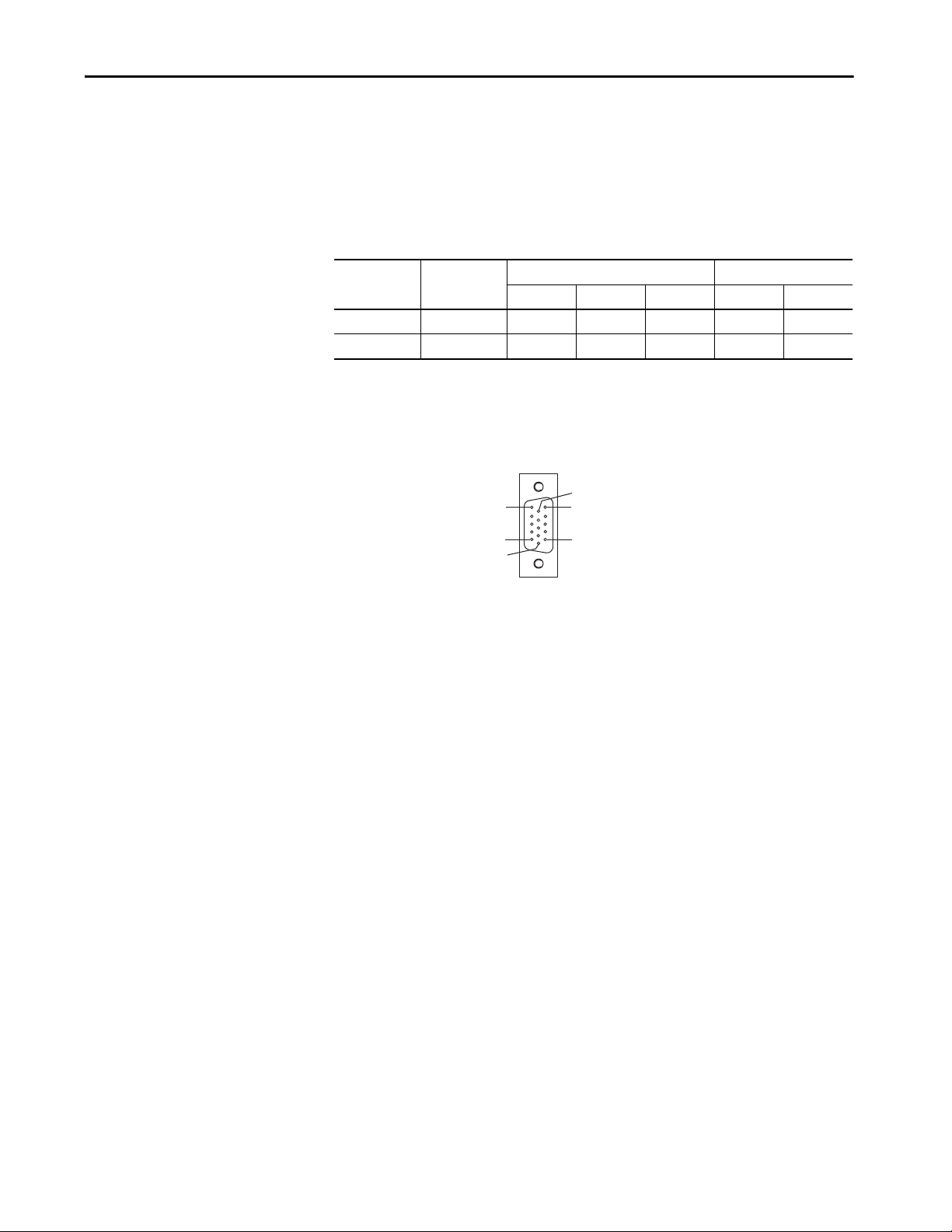
Kinetix 350 Drive Connector Data Chapter 3
Pin 11
Pin 6
Pin 15
Pin 1
Pin 10
Pin 5
Feedback Power Supply
The Kinetix 350 drive generates +5V and +9V DC for motor feedback power.
Short circuit protection and separate common mode filtering for each channel
is included.
Table 23 - Motor Feedback Power Specifications
Supply Reference
Min Nominal Max Min Max
+5V DC EPWR_5V 5.13 5.4 5.67 0 400
+9V DC EPWR_9V 8.3 9.1 9.9 0 275
(1) 400 mA on the 5V supply with no load on the 9V supply.
(2) 300 mA on the 5V supply with 150 mA on the 9V supply.
(3) 275 mA on the 9V supply with no load on the 5V supply.
Voltage Current mA
Figure 26 - Pin Orientation for 15-pin Motor Feedback (MF) Connector
(1) (2)
(2) (3)
Rockwell Automation Publication 2097-UM002D-EN-P - April 2017 49
Page 50

Chapter 3 Kinetix 350 Drive Connector Data
Notes:
50 Rockwell Automation Publication 2097-UM002D-EN-P - April 2017
Page 51
Chapter 4
Connect the Kinetix 350 Drive System
Top ic Pa ge
Basic Wiring Requirements 51
Grounding Your Kinetix 350 Drive System 58
Power Wiring Requirements 60
Wiring Guidelines 61
Wiring the Kinetix 350 Drive Connectors 62
Apply the Motor Cable Shield Clamp 69
Feedback and I/O Cable Connections 70
Wiring the Feedback and I/O Connectors 72
Shunt Resistor Connections 74
Ethernet Cable Connections 74
Basic Wiring Requirements
This section contains basic information on how to wire the Kinetix® 350 drive.
ATT EN TI ON : Plan the installation of your system so that you can cut, drill,
tap, and weld with the system that is removed from the enclosure. Because
the system is of the open type construction, be careful to keep any metal
debris from falling into it. Metal debris or other foreign matter can become
lodged in the circuitry, which can result in damage to components.
SHOCK HAZARD: To avoid hazard of electrical shock, perform all mounting and
wiring of the Bulletin 2097 drive before you apply power. Once power is applied,
connector terminals can have voltage present even when not in use.
IMPORTANT This section contains common PWM servo system wiring configurations,
size, and practices that can be used in most applications. National Electrical
Code, local electrical codes, special operating temperatures, duty cycles, or
system configurations take precedence over the values and methods
provided.
Rockwell Automation Publication 2097-UM002D-EN-P - April 2017 51
Page 52

Chapter 4 Connect the Kinetix 350 Drive System
Recommended Cables
The Motor Power Cable Compatibility table on page 65 and Motor Feedback
Cables for Specific Motor/Feedback Combinations table on page 70 show the
cables Rockwell Automation® recommends that you use with the Kinetix® 350
drive.
IMPORTANT Factory-made cables are designed to minimize EMI and are recommended
over hand-built cables to optimize system performance.
If it is necessary for you to build or modify your own cable, follow these
guidelines:
• Connect the cable shield to the connector shells on both ends of the
cable with a complete 360° connection.
• Use twisted-pair cable whenever possible. Twist differential signals with
each other and twist single-ended signals with the appropriate ground
return.
See the Kinetix Motion Control Selection Guide, publication
KNX-SG001
and motor-end connector kit catalog numbers.
, for low-profile connector kit, drive-end (mating) connector kit,
Determine the Input Power Configuration
Route Power and Signal Wiring
When you route power and signal wiring on a machine or system, radiated
noise from nearby relays, transformers, and other electronic drives can be
induced into motor or encoder feedback signals, input/output
communication, or other sensitive low voltage signals. Radiated noise can cause
system faults and communication anomalies.
See Electrical Noise Reduction
low voltage cables in wireways. See the System Design for Control of Electrical
Noise Reference Manual, publication GMC-RM001
This section contains examples of typical single-phase and three-phase facility
input power that is wired to single-phase and three-phase Kinetix 350 drives.
The grounded power configuration lets you ground your single-phase or threephase power at a neutral point. Match your secondary to one of the examples
and be certain to include the grounded neutral connection. See Table 68 on
page 152 for leakage currents.
on page 24 for examples of routing high and
, for more information.
52 Rockwell Automation Publication 2097-UM002D-EN-P - April 2017
Page 53
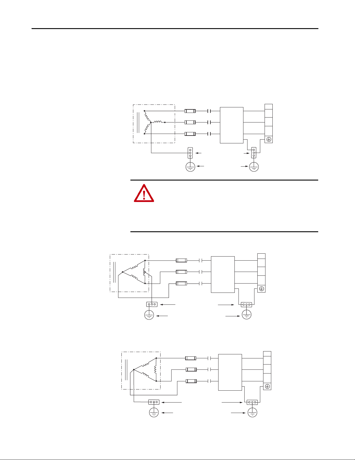
Connect the Kinetix 350 Drive System Chapter 4
L3
L2
L1
IPD
L3
L2
L1
E
L3
L2
L1
L3
L2
L1
Transformer (WYE) Secondary
Kinetix 350 Drives
Three-phase AC Input
Bonded Cabinet Ground Bus
Ground Grid or
Power Distribution Ground
AC Line
Filter
M1
Contac tor
Input Fusing
Feeder and branch short circuit
protection is not illustrated.
2097-V34PRx-LM
Transformer (Delta) Secondary
Kinetix 350 Drives
Three-phase AC Input
AC Line
(1)
Filter
Bonded Cabinet Ground Bus
Ground Grid or Power Distribution Ground
M1
Contac tor
Input Fusing
Feeder and branch short circuit
protection is not illustrated.
2097-V33PRx-LM
Transformer (Delta) Secondary
Kinetix 350 Drives
Three-phase AC Input
AC Line
(1)
Filter
Bonded Cabinet Ground Bus
Ground Grid or Power Distribution Ground
M1
Contactor
Input Fusing
Feeder and branch short circuit
protection is not illustrated.
2097-V33PRx-LM
Three-phase Power Wired to Three-phase Drives
These examples illustrate grounded three-phase power that is wired to threephase Kinetix 350 drives when phase-to-phase voltage is within drive
specifications.
Figure 27 - Three-phase (400/480V) Power Configuration (WYE Secondary)
ATT EN TI ON : For the 480V Kinetix 350 drives to meet proper voltage
creepage and clearance requirements, each phase voltage to ground must be
less than or equal to 300V AC rms. This requirement means that the power
system must use a center grounded wye secondary configuration for 400/
480V AC mains.
See Appendix C for leakage currents.
Figure 28 - Three-phase (240V) Power Configuration (Delta Secondary)
L3
L2
L3
L2
L1
L3
L2
L1
E
L1
(1) Leakage current from the line filter, in thi s configuration, typically is higher than a balanced (center ground) configuration.
IPD
L3
L2
L1
Figure 29 - Three-phase (240V) Power Configuration (Delta Secondary)
L3
L2
(1) Leakage current from the line filter, in thi s configuration, typically is higher than a balanced (center ground) configuration.
Rockwell Automation Publication 2097-UM002D-EN-P - April 2017 53
L1
L3
L2
L1
L3
L2
L1
E
IPD
L3
L2
L1
Page 54
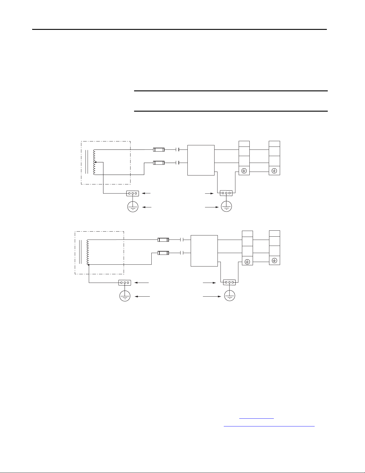
Chapter 4 Connect the Kinetix 350 Drive System
Transformer Secondary
Transformer Secondary
Bonded Cabinet Ground Bus
Ground Grid or
Power Distribution Ground
AC Lin e
Filter
AC Lin e
Filter
120V AC
Output
240V AC
Output
Bonded Cabinet Ground Bus
Ground Grid or
Power Distribution Ground
Kinetix 350 Drives
Single-phase AC Input
Kinetix 350 Drives
Single-phase AC Input
M1
Contactor
Input Fusing
M1
Contactor
Input Fusing
2097-V31PRx -LM
(1)
2097-V31PRx-LM
2097-V32PRx-LM
2097-V33PRx -LM
Single-phase Power Wired to Single-phase Drives
These examples illustrate grounded single-phase power that is wired to singlephase Kinetix 350 drives when phase-to-phase voltage is within drive
specifications.
IMPORTANT The 2097-V32PRx-LM models have integrated AC line filters and do not
require the AC line filter that is shown in this diagram.
Figure 30 - Single-phase Grounded Power Configurations
L1
L2
L1
L2 (Neutral)
L1
L2
L1
L2/N
L1
L2
E
L1
L2/N
E
(1) This configuration applies to voltage-doubler operation for 2097-V31PRx-LM drives.
IPD
L1
L2/N
IPD
L1
N
If you reduce transformer output, the motor speed is reduced. Feeder and
branch short circuit protection is not illustrated.
IPD
L1
L2
IPD
L1
L2
Voltage Doubler Operation
You can wire the 2097-V31PRx-LM drives with 120V input voltage and
achieve twice the output voltage. To use the voltage-doubler circuit, connect
the 120V single-phase input power to the IPD-L1 and IPD-N terminals.
For Kinetix 350 drive power specifications, refer to Kinetix Servo Drives
Specifications Technical Data, publication KNX-TD003
drive input wiring diagrams, refer to Power Wiring Examples on page 131
54 Rockwell Automation Publication 2097-UM002D-EN-P - April 2017
. For Kinetix 350
.
Page 55

Connect the Kinetix 350 Drive System Chapter 4
L1
L2
L3
IPD
L1
L2
IPD
L1
L2
IPD
L1
L2
L1
L2
L3
L2
L3
L1
Transformer
(WYE) Secondary
Grounded Neutral
Kinetix 350 Drives
(System A)
Single-phase AC Input
Input Fusing
M1
(1)
M2
(1)
M3
(1)
Ground Grid or
Power Distribution Ground
Bonded Cabinet
Ground Bus
Kinetix 350 Drives
(System B)
Single-phase AC Input
Kinetix 350 Drives
(System C)
Single-phase AC Input
Input Fusing
Input Fusing
2097-V32PRx-LM
Isolation Transformer in Grounded Power Configurations
When you are using an isolation transformer, attach the chassis ground wire to
the neutral connection. This grounded neutral connection does the following :
• Prevents the system from floating and avoids any high voltages that can
otherwise occur, for example due to static electricity
• Provides a solid earth path for fault conditions
ATT EN TI ON : If the supply transformer is an auto transformer (not
recommended), do not add a chassis earth ground. A chassis earth ground is
already included elsewhere in the system and addition of another creates a
short.
Three-phase Power Wired to Single-phase Drives
This example illustrates grounded three-phase power that is wired to singlephase Kinetix 350 drives when phase-to-phase voltage is within drive
specifications.
Figure 31 - Single-phase Amplifiers on Three-phase Power (WYE)
(1) Contactors (MI, M2, and M3) can be optional. For more information, see Understanding the Machinery Directive, publication
SHB-900. AC line filter is optional, but is required for CE compliance.
Feeder short circuit protection is not illustrated.
Rockwell Automation Publication 2097-UM002D-EN-P - April 2017 55
Page 56
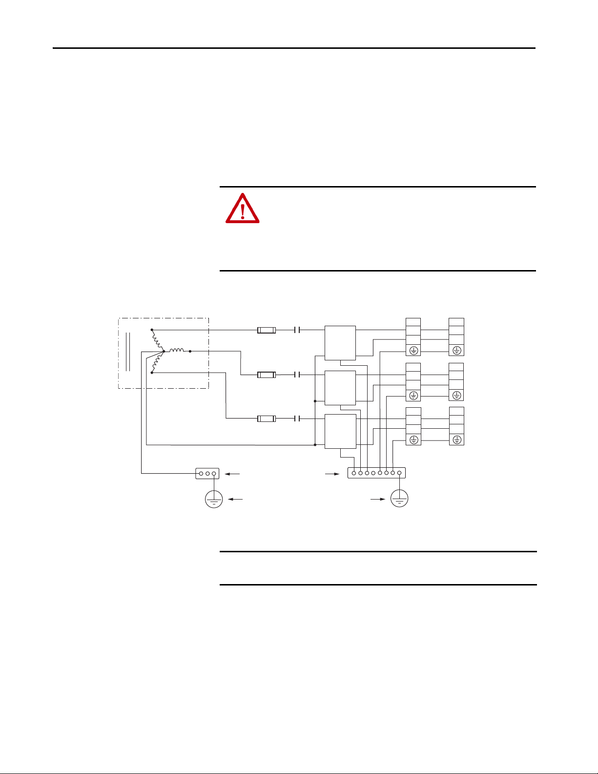
Chapter 4 Connect the Kinetix 350 Drive System
L1
L2
L3
L1
L2
L1
L2
L1
L2
IPD
L1
N
IPD
L1
N
IPD
L1
N
L1
L2
L1
L2
L1
L2
E
E
E
IPD
L1
L2
IPD
L1
L2
IPD
L1
L2
Bonded Cabinet Ground Bus
Transformer (WYE) Secondary
Ground Grid or Power Distribution Ground
AC Line
Filter
AC Line
Filter
AC Line
Filter
Kinetix 350 Drives
(System A)
Single-phase AC Input
Grounded
Neutral
Grounded Neutral
Kinetix 350 Drives
(System A)
Single-phase AC Input
Kinetix 350 Drives
(System A)
Single-phase AC Input
M1
Contac tor
Input Fusing
2097-V31PRx-LM 2097-V33PRx-LM
This example illustrates grounded three-phase power that is wired to singlephase Kinetix 350 drives when phase-to-phase voltage exceeds drive
specifications.
A neutral must be connected when single-phase drives are attached to a threephase isolating transformer secondary. It is not necessary that all three-phases
be loaded with drives, but each drive must have its power return via the neutral
connection
.
ATT EN TI ON : Failure to connect the neutral can result in supply voltage
swings at the individual drives. This condition occurs when the neutral point
moves vectorially as a result of load variations that individual drives
experience. The supply voltage swing can cause undervoltage and
overvoltage trips on the drives, and the drive can be damaged if the
overvoltage limit is exceeded.
Figure 32 - Single-phase Amplifiers (One AC Line Filter Per Drive)
Feeder and branch short circuit protection is not illustrated.
56 Rockwell Automation Publication 2097-UM002D-EN-P - April 2017
IMPORTANT An AC line filter for each drive is the preferred configuration and required for
CE compliance.
Page 57

Connect the Kinetix 350 Drive System Chapter 4
Voiding of CE Compliance
The three-phase and neutral in-line filter applications that are described Three-
phase Power Wired to Single-phase Drives on page 55 are not adequate for CE
compliance for EMC. Therefore, EMC validity and CE marking by Rockwell
Automation is voided when three-phase and neutral in line filters are used.
ATT EN TI ON : The three-phase isolation transformer and neutral in-line filter
applications that are described in this document have not been tested for
EMC by Rockwell Automation. The products that are used in such
installations are not considered CE marked by Rockwell Automation.
If this three-phase isolation transformer and neutral in-line filter application is
used, the responsibility for EMC validation lies with the user and CE marking of
the system becomes your responsibility.
If CE compliance is a customer requirement, use single-phase line filters that
Rockwell Automation has tested and are specified for the product. See Kinetix
Servo Drives Specifications Technical Data, publication KNX-TD003
numbers.
for catalog
Rockwell Automation Publication 2097-UM002D-EN-P - April 2017 57
Page 58

Chapter 4 Connect the Kinetix 350 Drive System
Bonded Cabinet
Ground Bus
Ground Grid or Power
Distribution Ground
Braided
Ground Strap
Ground Stud
Grounding Your Kinetix 350 Drive System
All equipment and components of a machine or process system must have a
common earth ground point that is connected to their chassis. A grounded
system provides a safety ground path for short circuit protection. Grounding
your modules and panels minimize shock hazard to personnel and damage to
equipment caused by short circuits, transient overvoltages, and accidental
connection of energized conductors to the equipment chassis. For CE
grounding requirements, refer to CE Requirements
in Chapter 1.
IMPORTANT To improve the bond between the Kinetix 350 drive and subpanel, construct
your subpanel out of zinc plated (paint-free) steel.
Ground Your Drive to the System Subpanel
ATT EN TI ON : The National Electrical Code contains grounding requirements,
conventions, and definitions. Follow all applicable local codes and
regulations to ground your system safely. See the Figure 33
grounding your Kinetix 350 drive. See Appendix A
for the power wiring
diagram for your Kinetix 350 drive.
If the Kinetix 350 drive is mounted on a painted subpanel, ground the drive to
a bonded cabinet ground bus by using a braided ground strap or 4.0 mm
(12 AWG) solid copper wire 100 mm (3.9 in.) long.
for details on
Figure 33 - Connecting the Braided Ground Strap Example
For drive dimensions, refer to Product Dimensions in Kinetix Servo Drives
Specifications Technical Data, publication KNX-TD003
.
58 Rockwell Automation Publication 2097-UM002D-EN-P - April 2017
Page 59

Connect the Kinetix 350 Drive System Chapter 4
Bonded Ground Bar
(option al)
Bonded Cabinet
Ground Bus
Ground Grid or Power
Distribution Ground
Always follow NEC and
applicable local codes.
Chassis Ground
Chassis Ground
Chassis Ground
Chassis Ground
Always follow NEC and
applicable local codes.
Ground Grid or Power
Distribution Ground
Bonded Ground
Bus
Figure 34 - Chassis Ground Configuration (Multiple Kinetix 350 Drives on One Panel)
Ground Multiple Subpanels
To ground multiple subpanels, refer to the Figure 35 HF bonding is not
illustrated. For information, see Bonding Multiple Subpanels
Figure 35 - Subpanels Connected to a Single Ground Point
on page 26.
Rockwell Automation Publication 2097-UM002D-EN-P - April 2017 59
Page 60

Chapter 4 Connect the Kinetix 350 Drive System
Power Wiring Requirements
The wire must be made of copper with 75 °C (167 °F) minimum rating.
Phasing of main AC power is arbitrary and an earth ground connection is
required for safe and proper operation. See Power Wiring Examples
page 131
for interconnect diagrams.
IMPORTANT The National Electrical Code and local electrical codes take precedence over
the values and methods provided.
Table 24 - Kinetix 350 Drive Power Wiring Requirements
Cat. No. Description
2097-V31PR0-LM
2097-V32PR0-LM
2097-V32PR2-LM
2097-V33PR1-LM
2097-V33PR3-LM
2097-V34PR3-LM
2097-V34PR5-LM
2097-V34PR6-LM
2097-V32PR4-LM
2097-V33PR5-LM
2097-V31PR2-LM
2097-V33PR6-LM
2097-V31PR0-LM
2097-V31PR2-LM
2097-V32PR0-LM
2097-V32PR2-LM
2097-V32PR4-LM
2097-V33PR1-LM
2097-V33PR3-LM
2097-V33PR5-LM
2097-V34PR3-LM
2097-V34PR5-LM
2097-V34PR6-LM
2097-V33PR6-LM 4.0 (12) 7 (0.28) 0.5 (4.5)
2097-V31PR0-LM
2097-V31PR2-LM
2097-V32PR0-LM
2097-V32PR2-LM
2097-V32PR4-LM
2097-V33PR1-LM
2097-V33PR3-LM
2097-V33PR5-LM
2097-V34PR3-LM
2097-V34PR5-LM
2097-V34PR6-LM
2097-V33PR6-LM 4.0 (12) 7 (0.28) 0.5 (4.5)
2097-V3xPRx-LM
2097-V3xPRx-LM
(1) Use for only shunt resistor connection.
(2) Use for bypassing only the STO circuit.
(3) Applies to 2097-V33PRx-LM, and 2097-V34PRx-LM drive modules.
(4) Applies to 2097-V31PRx-LM drive modules.
(5) Applies to 2097-V32PRx-LM drive modules.
Mains input power
(IPD connector)
Motor power
(MP connector)
Shunt/DC Bus
(BC connector)
Control back-up power
(BP connector)
Safe torque-off
(STO connector)
Pins Signals
(1)
(2)
STO-1
(2)
STO-2
STO-3
STO-4
STO-5
STO-6
Ter mina ls
L3
L2
L1
PE
PE
W
V
U
+
+
SH
-
-
+24V DC
-24V DC
+24V DC Control
Control COM
Safety Status
Safety Input 1
Safety COM
Safety Input 2
L2/N
L1
N
(3)
PE
L2
L1
PE
(4)
Recommended Wire Size
mm² (AWG)
Motor power cable depends
on motor/drive combination.
2.5 (14)
(5)
4.0 (12) 7 (0.28) 0.5 (4.5)
6.0 (10) 7 (0.28)
2.5 (14) 7 (0.28) 0.5 (4.5)
2.5 (14) 7 (0.28) 0.5 (4.5)
1.5 (16) 6 (0.25) 0.5 (4.5)
Strip Length
mm (in.)
7 (0.28) 0.5 (4.5)
Tor que Valu e
N•m (lb•in)
0.56…0.79
(5.0…7.0)
on
60 Rockwell Automation Publication 2097-UM002D-EN-P - April 2017
Page 61

Connect the Kinetix 350 Drive System Chapter 4
ATT EN TI ON : To avoid personal injury and/or equipment damage, make sure
that installation complies with specifications regarding wire types,
conductor sizes, branch circuit protection, and disconnect devices. The
National Electrical Code (NEC) and local codes outline provisions for safely
installing electrical equipment.
To avoid personal injury and/or equipment damage, make sure that motor
power connectors are used for only connection purposes. Do not use them to
turn the unit on and off.
To avoid personal injury and/or equipment damage, make sure that shielded
power cables are grounded to prevent potentially high voltages on the shield.
Wiring Guidelines
Use these guidelines as a reference when wiring the connectors on your
Kinetix 350 drive power modules.
IMPORTANT For connector locations of the Kinetix 350 drives, refer to Kinetix 350 Drive
Connectors and Indicators on page 34.
When you tighten screws to secure the wires, refer to the tables that begin
on page 60
When you remove insulation from wires, refer to the tables that begin on
page 60
IMPORTANT To improve system performance, run wires and cables in the wireways as
established in Establish Noise Zones
Follow these steps when wiring the connectors on your Kinetix 350 drive
modules.
1. Prepare the wires for attachment to each connector plug by removing
insulation equal to the recommended strip length.
IMPORTANT Use caution not to nick, cut, or otherwise damage strands as you
for torque values.
for strip lengths.
on page 27.
remove the insulation.
2. Route the cable/wires to your Kinetix 350 drive.
3. Insert wires into connector plugs.
See connector pinout tables in Chapter 3
in Appendix A
4. Tighten the connector screws.
5. Gently pull on each wire to make sure it does not come out of its
terminal; reinsert and tighten any loose wires.
6. Insert the connector plug into the module connector.
Rockwell Automation Publication 2097-UM002D-EN-P - April 2017 61
.
or the interconnect diagrams
Page 62

Chapter 4 Connect the Kinetix 350 Drive System
Kinetix 350 Drive, Front View
Wiring the Kinetix 350 Drive Connectors
This section provides examples and wiring tables to assist you when you make
connections to the Kinetix 350 drive.
Wire the Safe Torque-off (STO) Connector
For the safe torque-off (STO) connector pinouts, feature descriptions, and
wiring information, see Chapter 6
on page 101.
Wire the Back-up Power (BP) Connector
+
+24V DC
24
-24V DC
-
Table 25 - Back-up Power (BP) Connector
Drive Cat. No. Terminals
2097-V3xPRx-LM
+24V DC
-24V DC
Recommended
Wire Size
mm² (AWG)
1.5 (16) 6 (0.25) 0.5 (4.5)
Strip Length
mm (in.)
Torque Value
N•m (lb•in)
62 Rockwell Automation Publication 2097-UM002D-EN-P - April 2017
Page 63

Wire the Input Power (IPD) Connector
Kinetix 350
Drive
Connect the Kinetix 350 Drive System Chapter 4
L2
L2
L1
L1
L2/N
PE
L2/N
L1
L1
N
N
PE
Table 26 - Input Power (IPD) Connector
Drive Cat. No. Terminals
2097-V31PR0-LM
2097-V32PR0-LM
2097-V32PR2-LM
2097-V33PR1-LM
2097-V33PR3-LM
2097-V34PR3-LM
2097-V34PR5-LM
2097-V34PR6-LM
2097-V32PR4-LM
2097-V33PR5-LM
2097-V31PR2-LM
2097-V33PR6-LM
(1) Applies to 2097-V33PRx-LM, and 2097-V34PRx-LM drive modules.
(2) Applies to 2097-V31PRx-LM drive modules.
(3) Applies to 2097-V32PRx-LM drive modules.
L3
L2
L1
PE
L2/N
L1
(1)
N
PE
(2)
L3
L3
L2
L2
L1
L1
PE
Recommended
Wire Size
mm² (AWG)
Strip Length
mm (in.)
Torque Value
N•m (lb•in)
2.5 (14) 7 (0.28) 0.5 (4.5)
L2
L1
(3)
PE
4.0 (12) 7 (0.28) 0.5 (4.5)
6.0 (10) 7 (0.28)
0.56…0.79
(5.0…7.0)
Rockwell Automation Publication 2097-UM002D-EN-P - April 2017 63
Page 64

Chapter 4 Connect the Kinetix 350 Drive System
W
V
U
PE
W
V
U
Kinetix 350 Drive
Bottom View
Wire the Motor Power (MP) Connector
Connections to the motor power (MP) connector include rotary motors and
rotary motor driven actuators.
Table 27 - Motor Power (MP) Termination Specifications
Drive Cat. No. Terminals
2097-V31PR0-LM
2097-V31PR2-LM
2097-V32PR0-LM
2097-V32PR2-LM
2097-V32PR4-LM
2097-V33PR1-LM
2097-V33PR3-LM
2097-V33PR5-LM
2097-V34PR3-LM
2097-V34PR5-LM
2097-V34PR6-LM
2097-V33PR6-LM 4.0 (12)
PE
W
V
U
Recommended
Wire Size
mm² (AWG)
2.5 (14)
Strip Length
mm (in.)
7 (0.28) 0.5 (4.5)
Torque Value
N•m (lb•in)
Cable Shield Terminations
Factory-supplied motor power cables for MP-Series™ and TL-Series™ motors
and actuator are shielded. The braided cable shield must terminate near the
drive during installation. Remove small portion of the cable jacket to expose
the shield braid and clamp the exposed shield to the panel.
ATT EN TI ON : To avoid hazard of electrical shock, ensure shielded power
cables are grounded at a minimum of one point for safety.
IMPORTANT For TL-Series™ motors, also connect the 152 mm (6.0 in.) termination wire
to the closest earth ground.
See Pigtail Terminations
64 Rockwell Automation Publication 2097-UM002D-EN-P - April 2017
on page 65 for more information.
Page 65
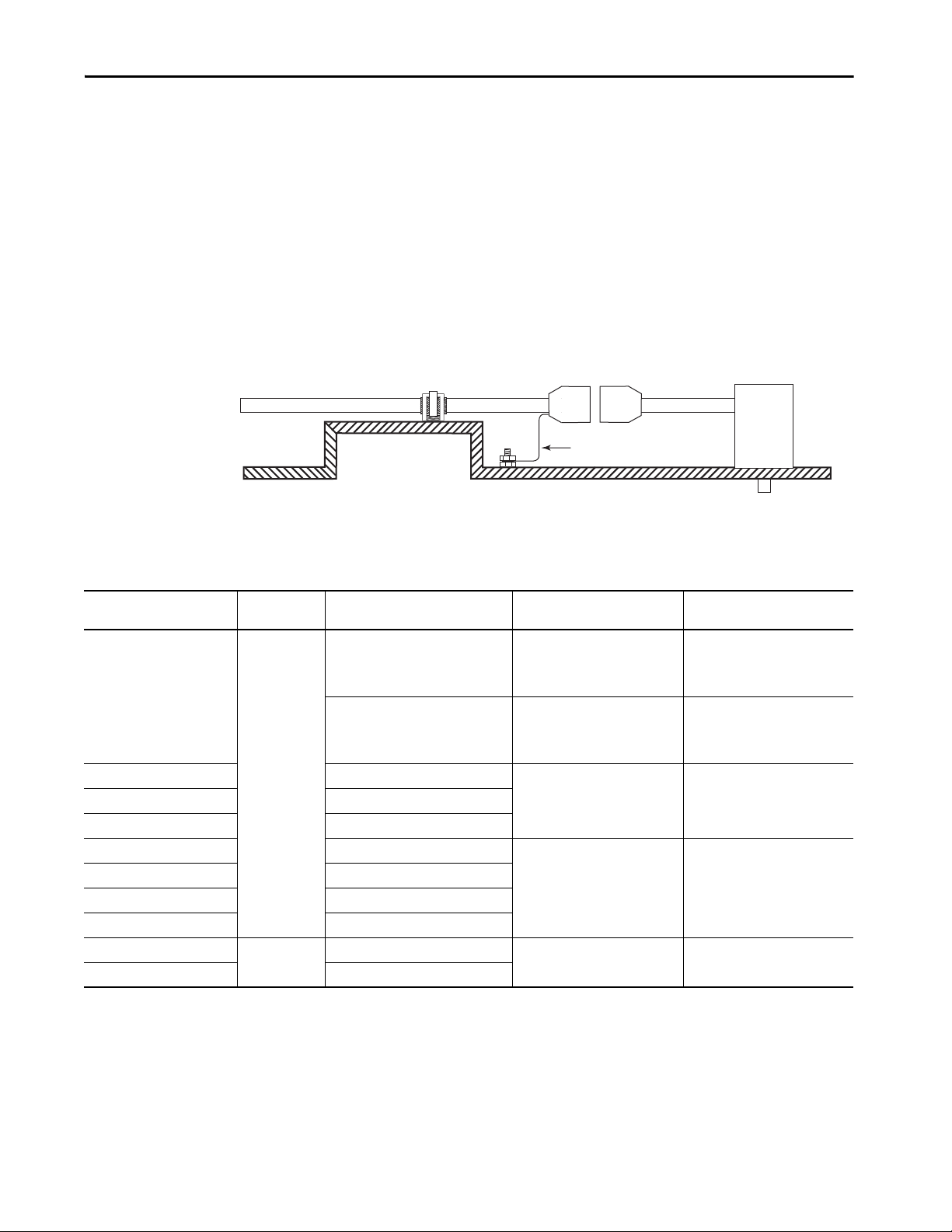
Connect the Kinetix 350 Drive System Chapter 4
(1)
(1)
Pigtail Cable
TL-Series
Motor
Conne ctors
Motor Power Cable
Machine Frame
150 mm (6.0 in.) Termination
Cable Braid Clamped
(1)
to Machine Frame
Pigtail Terminations
TL-Series motors have a short pigtail cable that connects to the motor, but is
not shielded. The preferred method for grounding the TL-Series power cable
on the motor side is to expose a section of the cable shield and clamp it directly
to the machine frame. The motor power cable also has a 150 mm (6.0 in.)
shield termination wire with a ring lug that connects to the closest earth
ground. Use this method and the cable clamp. The termination wire can be
extended to the full length of the motor pigtail if necessary, but it is best to
connect the supplied wire directly to ground without lengthening.
Figure 36 - Pigtail Terminations
(1) Remove paint from machine frame to be sure of proper HF-bond between machine frame, motor case, shield clamp, and ground
stud.Motor Power Cable Compatibility
Table 28 - Motor Power Cable Compatibility
Motor/Actuator Connector Motor/Actuator Cat. No.
MPL-A/B15xxx-4xAA and
MPL-A/B2xxx-4xAA
MP-Series™ (Bulletin MPL)
MPL-A/B3xxx-7xAA,
MPL-A/B4xxx-7xAA, and
MPL-A/B45xxx-7xAA
MP-Series (Bulletin MPS) MPS-A/Bxxxx
MP-Series (Bulletin MPAS) MPAS-A/Bxxxx
MP-Series (Bulletin MPAR) MPAR-A/B1xxx and MPAR-A/B2xxx
MP-Series (Bulletin MPM) MPM-A/Bxxxx
MP-Series (Bulletin MPF) MPF-A/Bxxxx
MP-Series (Bulletin MPAR) MPAR-A/B3xxx
MP-Series (Bulletin MPAI) MPAI-A/Bxxxx
TL-Series (Bulletin TLY)
TL-Series (Bulletin TLAR) TLAR-Axxxx
(1) You must remove the motor-side o-ring when you are using 2090-CPxM7DF-xxAxx cables.
Circular DIN
Circular Plastic
TLY-Axxxx
Motor Power Cables
(with Brake Wires)
Motor Power Cables
(without Brake Wires)
2090-XXNPMF-xxSxx
(standard)
2090-CPBM4DF-xxAFxx
2090-CPWM4DF-xxAFxx
(continuous-flex)
(continuous-flex)
2090-CPBM7DF-xxAAxx
(standard)
2090-CPBM7DF-xxAFxx
(continuous-flex)
(1)
(1)
2090-CPWM7DF-xxAAxx
(standard)
2090-CPWM7DF-xxAFxx
(continuous-flex)
(1)
(1)
2090-XXNPMF-xxSxx
(standard)
2090-CPBM4DF-xxAFxx
2090-CPWM4DF-xxAFxx
(continuous-flex)
(continuous-flex)
2090-CPBM7DF-xxAAxx
(standard)
2090-CPBM7DF-xxAFxx
(continuous-flex)
(1)
(1)
2090-CPWM7DF-xxAAxx
(standard)
2090-CPWM7DF-xxAFxx
(continuous-flex)
(1)
(1)
2090-CPBM6DF-16AAxx (standard) 2090-CPWM6DF-16AAxx (standard)
Rockwell Automation Publication 2097-UM002D-EN-P - April 2017 65
Page 66

Chapter 4 Connect the Kinetix 350 Drive System
Motor Cable
Shield Clamp
Motor Power (MP) Connector Plug
Kinetix 350 Drive
This diagram shows an example of three-phase power wires for motors/
actuators that have no brakes. Thermal switch wires are included in the
feedback cable.
See Kinetix 350 Drive/Rotary Motor Wiring Examples
for interconnect diagrams.
Figure 37 - Motor Power Terminations (Only Three-phase Wires)
that start on page 134
The cable shield clamp that is shown in Figure 37 is mounted to the subpanel.
Ground and secure the motor power cable in your system following
instructions on page 69
66 Rockwell Automation Publication 2097-UM002D-EN-P - April 2017
.
Page 67

Connect the Kinetix 350 Drive System Chapter 4
1
2
3
To M ot or
6
7
5
8
4
This diagram shows an example of wiring with three-phase power wires and
brake wires. The brake wires have a shield braid that is shown in Figure 38
as
gray, which folds back under the cable clamp before the conductors are
attached to the motor brake circuit. Thermal switch wires are included in the
feedback cable.
See Kinetix 350 Drive/Rotary Motor Wiring Examples
that begin on page 134
for interconnect diagrams.
Figure 38 - Motor Power Terminations (Three-phase and Brake Wires)
Item Description Item Description
(1)
1
24V power supply 5 I/O (IOD) connector
(1)
2
Relay and diode assembly
3 Minimize unshielded wires in brake circuit 7 Motor power (MP) connector
4 MP-Series cable brake wires 8 Cable clamp
(1) User supplied. Size as required by motor brake, See Motor Brake Currents on page 140.
(2) Pins 43 and 44 are configured as MTR_ BRAKE+ and MTR_BRAKE- Common respectively. Wire the output as sourcing and set brake engage and
disengage times for motor selected. Motor brake is active on enable.
(3) Diode 1N4004 (1 A @ 400V DC) or equivalent. See Interconnect D iagram Notes
(4) Exposed shield under clamp and place within 50…75 mm (2…3 in.) of drive, see page 69
Rockwell Automation Publication 2097-UM002D-EN-P - April 2017 67
(3)
6 2097-V3xPRx-LM Kinetix 350 drive
that being on page 131.
for details.
(2)
(4)
Page 68
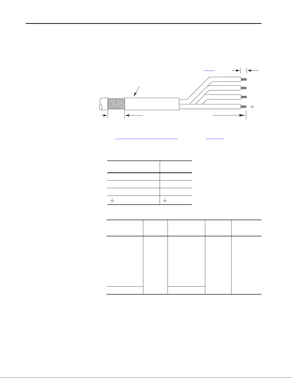
Chapter 4 Connect the Kinetix 350 Drive System
Motor Power Cable
Exposed Braid
25.4 mm (1.0 in.)
Outer Insulation
As required to have ground clamp within
50…75 mm (2…3 in.) of the drive.
Strip Length (See Tab le 30
)
Cable shield and lead preparation are provided with most Allen-Bradley® cable
assemblies. Follow these guidelines if your motor power cable shield and wires
require preparation.
Figure 39 - Cable Shield and Lead Preparation
U
V
W
See Shunt Resistor Wiring Example that being on page 133 for interconnect
diagrams.
Table 29 - Motor Power (MP) Connector
MP-Series or TL-Series Servo
Motor
U / Brown U
V / Black V
W / Blue W
Green/Yellow
Ter min al
Table 30 - Motor Power (MP) Termination Specifications
Drive Cat. No. Terminals
2097-V31PR0-LM
2097-V31PR2-LM
2097-V32PR0-LM
2097-V32PR2-LM
2097-V32PR4-LM
2097-V33PR1-LM
2097-V33PR3-LM
2097-V33PR5-LM
2097-V34PR3-LM
2097-V34PR5-LM
2097-V34PR6-LM
2097-V33PR6-LM 4.0 (12)
PE
W
V
U
Recommended
Wire Size
mm² (AWG)
2.5 (14)
Strip Length
mm (in.)
7 (0.28) 0.5 (4.5)
Tor que V alue
N•m (lb•in)
68 Rockwell Automation Publication 2097-UM002D-EN-P - April 2017
Page 69
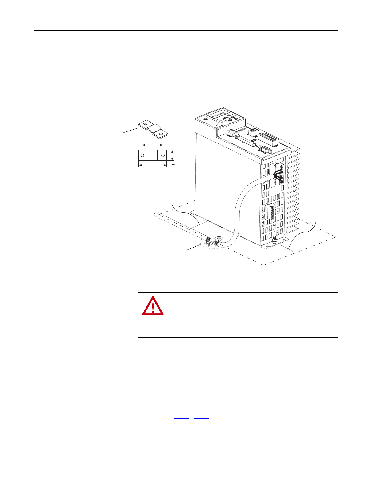
Connect the Kinetix 350 Drive System Chapter 4
If panel is painted, remove paint to
provide metal-to-metal contact.
Motor Power Ground
Shield Clamp
Dimensions are in mm (in.).
Apply the Motor Cable Shield Clamp
This procedure assumes that you have completed wiring your motor power
(MP) connector and are ready to apply the cable shield clamp.
Follow these steps to apply the motor cable shield clamp.
1. Locate a suitable position for installing cable shield clamp within
50…75 mm (2…3 in.) of the drive.
25
(1.0)
34.0
(1.34)
12.7
(0.50)
50…75
(2…3)
50…75
(2…3)
2. Lay out and drill holes for cable clamp.
ATT EN TI ON : Plan the installation of your system so that you can cut, drill,
tap, and weld with the system that is removed from the enclosure. Because
the system is of the open type construction, be careful to keep any metal
debris from falling into it. Metal debris or other foreign matter can become
lodged in the circuitry, which can result in damage to components.
3. Locate the position on the motor power cable that comes under the
clamp and remove about an inch of the cable jacket to expose the shield
braid.
4. Position the exposed portion of the cable braid directly in line with the
clamp.
5. Clamp the exposed shield to the panel by using the clamp and two
#6-32 x 1 screws provided.
6. Repeat step 1
…step 5 for each Kinetix 350 drive you are installing.
Rockwell Automation Publication 2097-UM002D-EN-P - April 2017 69
Page 70

Chapter 4 Connect the Kinetix 350 Drive System
Feedback and I/O Cable Connections
Factory made cables with premolded connectors are designed to minimize
EMI and are recommended over hand-built cables to improve system
performance. However, other options are available for building your own
feedback and I/O cables.
Table 31 - Options for Connecting Motor Feedback and I/O
Connection Option Cat. No. Cable By Using This Type of Cable
Premolded connectors N/A Motor feedback
Low-profile connector 2090-K2CK-D15M Motor feedback
I/O Terminal Block 2097-TB1 I/O interface User-supplied flying-lead cable.
Table 32 - Motor Feedback Cables for Specific Motor/Feedback Combinations
Motor Cat. No. Feedback Type
MPL-A/B15xxx-V/Ex4xAA,
MPL-A/B2xxx-V/Ex4xAA
MPL-A/B15xxx-Hx4xAA,
MPL-A/B2xxx-Hx4xAA
MPL-A/B3xxx-Hx7xAA,
MPL-A/B4xxx-Hx7xAA,
MPL-A/B45xxx-Hx7xAA
MPL-A/B3xxx-M/Sx7xAA,
MPL-A/B4xxx-M/Sx7xAA,
MPL-A/B45xxx-M/Sx7xAA
MPM-A/Bxxxxx-M/S
MPF-A/Bxxxx-M/S
MPAR-A/B3xxxx
MPAI-A/Bxxxx
MPS-A/Bxxxx-M/S
MPAS-A/Bxxxx-V/A
MPAR-A/B1xxxx,
MPAR-A/B2xxxx
TLY-Axxxx-B
TLY-Axxxx-H Incremental encoder
(1) You must remove the motor-side o-ring when you are using 2090-CPxM7DF-xxAxx cables.
High-resolution encoder
Incremental encoder
High-resolution encoder
High-resolution encoder
High-resolution encoder
Premolded Flying-lead
N/A
N/A
2090-CFBM7DD-CEAAxx
2090-CFBM7DD-CEAFxx
flex)
N/A
2090-CFBM6DD-CCAAxx (standard) 2090-CFBM6DF-CBAAxx (standard)TLAR-Axxxxx
See the table Tab le 32 for the premolded motor feedback
cable available for your motor.
See the table Tab le 32 for the flying-lead cable available for
your motor.
Feedback Cable
2090-XXNFMF-Sxx (standard)
2090-CFBM4DF-CDAFxx
(continuous-flex)
2090-XXNFMF-Sxx (standard)
2090-CFBM7DF-CDAFxx
(continuous-flex)
(1)
(standard)
(1)
(continuou s-
2090-CFBM7DF-CEAAxx
2090-CFBM7DF-CEAFxx
continuous-flex)
2090-XXNFMF-Sxx (standard)
2090-CFBM4DF-CDAFxx
(continuous-flex)
(1)
(1)
(standard)
(1)
(
70 Rockwell Automation Publication 2097-UM002D-EN-P - April 2017
Page 71

Connect the Kinetix 350 Drive System Chapter 4
Flying-lead Feedback Cable Pin-outs
Table 33 - 2090-XXNFMF-Sxx or 2090-CFBMxDF-xxAxxx Feedback Cable
Connector Pin
High-resolution Feedback
9V Encoder 5V Encoder 5V Encoder
1Sin+Sin+AM+1
2Sin-Sin-AM-2
3Cos+Cos+BM+3
4Cos-Cos-BM-4
5Data+Data+IM+5
6 Data- Data- IM- 10
9 Reserved EPWR_5V EPWR_5V 14
10 Reserved ECOM ECOM 6
11 EPWR_9V Reserved Reserved 7
12 ECOM Reserved Reser ved 6
13 TS+ T S+ TS+ 1 1
14 TS- TS - TS- –
15 Reserved Reserved S1 12
16 Reserved Reserved S2 13
17 Reserved Reser ved S3 8
Incremental
Feedback
Drive MF
Connector Pin
Table 34 - 2090-CFBM6DF-CBAAxx Feedback Cable
High Resolution Incremental Feedback
Connector Pin
TLY-Axxxx-B
TLAR-Axxxxx
TLY-Axxxx-H
6 BAT+ Reserved BAT+
9
10 AM- 2
Reserved
AM+ 1
11 BM+ 3
12 BM- 4
13 DATA+ IM+ 5
14 DATA- IM- 10
15
17 S2 13
Reserved
S1 12
19 S3 8
22 EPWR 5V EPWR 5V 14
23 ECOM and BAT- ECOM 6
24 Shield Shield Connector housing
Drive MF
Connector Pin
Rockwell Automation Publication 2097-UM002D-EN-P - April 2017 71
Page 72
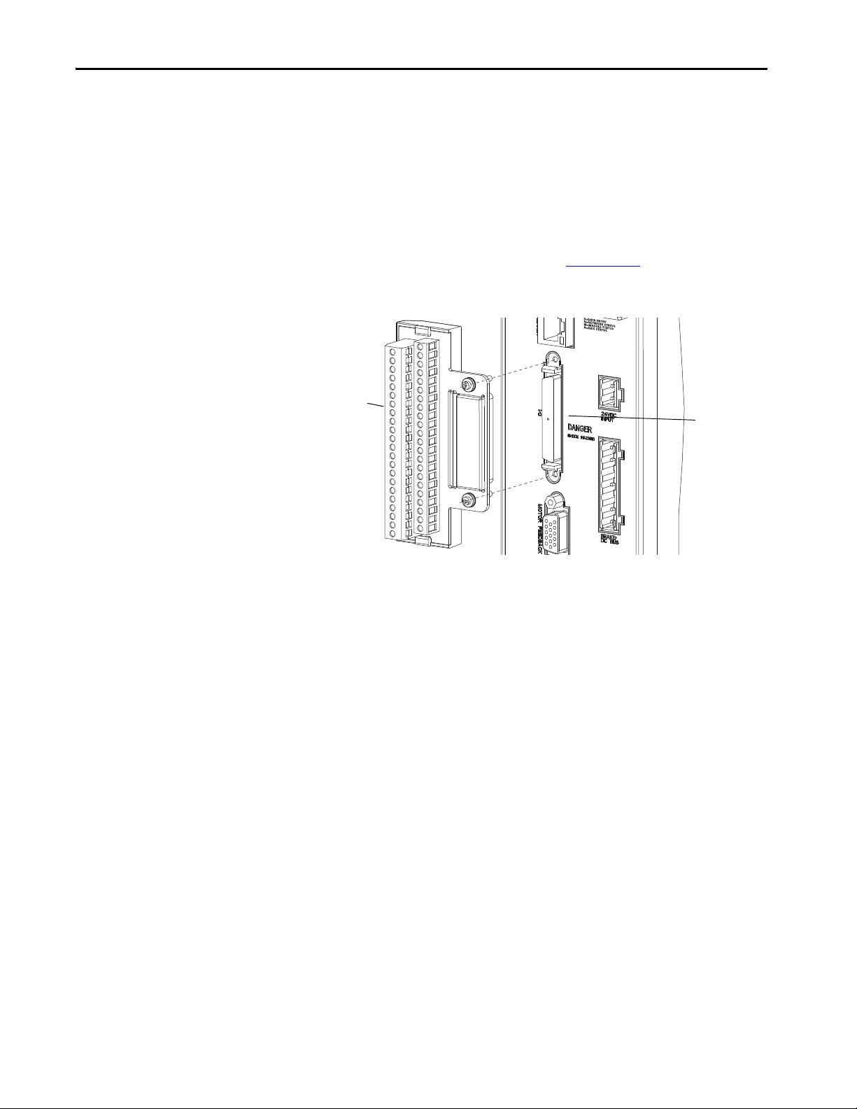
Chapter 4 Connect the Kinetix 350 Drive System
I/O (IOD)
Connector
2097-TB1
I/O Terminal
Expansion Block
Wiring the Feedback and I/O Connectors
These procedures assume that you have mounted your Kinetix 350 system,
completed the power wiring, and are ready to connect motor feedback.
Wire the I/O Connector
Connect your I/O wires to the IOD connector by using the 2097-TB1 I/O
Terminal Expansion Block. See the Kinetix 300 I/O Terminal Expansion
Block Installation Instructions, publication 2097-IN005
Figure 40 - Kinetix 350 Drive (IOD Connector and Terminal Block)
)
30
40
1
11
12
20
21
.
50
GND
29
72 Rockwell Automation Publication 2097-UM002D-EN-P - April 2017
Page 73
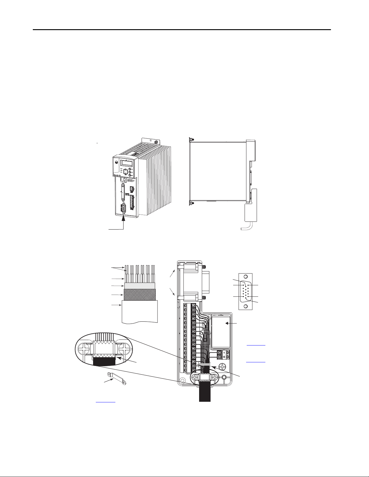
Connect the Kinetix 350 Drive System Chapter 4
2090-K2CK-D15M Connector Kit
with flying-lead feedback cable.
Motor Feedback (MF) Connector
Kinetix 350 Drive, Front View
(2097-V33PR5-LM drive is shown)
Kinetix 350 Drive, Side View
(2097-V33PR5-LM drive is shown)
1
2
34
5
6
7
8
91011121314150
Pin 1
Pin 10
Pin 5
Pin 11
Pin 6
Pin 15
15-pin (male) Motor Feedback
Low-profile Connector
See Appendix 3
for feedback signal
descriptions.
Tie Wrap
Exposed Braid Under Clamp
Bulletin 2090 Feedback Cable
Clamp
Outer Insulation
Braided Shield
Foil Shie ld
Wire I nsulation
Bare Wires
Bulletin 2090
Feedback Cable
Tur n cl amp ove r to hol d
small wires secure.
Mounting
Screws
See Appendix A
for the motor feedback
interconnect drawing for your application.
3.6V battery (catalog number 2090-DA-BAT2)
required for use with only TLY-Axxxx-B motors and TLAR
Axxxxx electric cylinders
(high-resolution 17-bit encoders).
Low Profile Connector Kit
(2090-K2CK-D15M)
See Low Profile Connector Kit Installation Instructions, publication
2093-IN005
, for connector kit specifications.
Wire the Low-profile Connector Kit
The 2090-K2CK-D15M low-profile connector kit is suitable for terminating
flying-lead motor feedback cables. Use it with the Kinetix 350 drive and all
motors with incremental or high-resolution feedback. It has a 15-pin, male, Dsub connector and is compatible with all Bulletin 2090 feedback cables.
TLY-Axxxx-B rotary motors and TLAR-Axxxxx electric cylinders also require
the 2090-DA-BAT2 battery to back up the high-resolution encoder.
Figure 41 - Kinetix 350 Drive (MF Connector)
)
Figure 42 - Wiring (15-pin) Flying-lead Feedback Cable Connections
2090-K2CK-D15M Connector Kit
Rockwell Automation Publication 2097-UM002D-EN-P - April 2017 73
Page 74

Chapter 4 Connect the Kinetix 350 Drive System
+
+
SH
-
-
Kinetix 350 Drive
Front view is shown.
Shunt/DC Bus
(BC) Connector
Shunt Resistor Connections
Follow these guidelines when wiring your 2097-Rx shunt resistor.
IMPORTANT When tightening screws to secure the wires, refer to the tables that begin on
for torque values.
page 60
IMPORTANT To improve system performance, run wires and cables in the wireways as
established in Chapter 2
• See Shunt Resistors
on page 30 for noise zone considerations.
• See Shunt Resistor Wiring Example
.
on page 133.
• See the installation instructions that are provided with your Bulletin
2097 shunt resistor, publication 2097-IN002
Figure 43 - Shunt/DC Bus (BC) Connector
.
Table 35 - Shunt Resistor Power Wiring Requirements
Accessory Description
2097-Rx Shunt resistor
Ethernet Cable Connections
This guideline assumes that you have your Logix5000™ Ethernet/IP module
Connects to
Ter min al s
+
SH
and Kinetix 350 drive that is mounted and ready to connect the network
cables.
IMPORTANT Connection to a larger network through an unmanaged switch without
Internet Group Management Protocol Snooping could cause degradation to
the larger network. Network switches without IEEE-1588 impacts the overall
system accuracy. Your overall network topology, number of connected nodes
and choice of EtherNet switch affects motion performance. For more detailed
information on how to design your network, please consult the Converged
Plantwide Ethernet (CPwE) Design and Implementation Guide, publication
ENET-TD001
.
The EtherNet/IP network is connected by using the Port 1 connector. See
page 34
to locate the Ethernet connector on your Kinetix 350 drive. See
74 Rockwell Automation Publication 2097-UM002D-EN-P - April 2017
Recommended Wire
Size
mm² (AWG)
2.5 (14) 0.5 (4.5)
Tor que Valu e
N•m (lb•in)
Page 75

Connect the Kinetix 350 Drive System Chapter 4
The Ethernet ports are on
bottom of controller.
CompactLogix™ Controller Platform
1769-L33ERM Shown
2
3
5
4
1
R
W
P
Compac tLogix Cont roller Plat form
1769-L33ERM Shown
Personal Compute r
1783-US05T
Stratix 2000
Switch
(1)
Kinetix 350 Drives
Figure 44 to locate the connector on your Logix5000™ communication
module.
Shielded Ethernet cable is available in lengths up to 78 m (256 ft). However,
the total length of Ethernet cable connecting drive-to-drive, drive-tocontroller, or drive-to-switch must not exceed 100 m (328 ft).
If the entire channel is constructed of stranded cable (no fixed cable), then this
equation is for calculating maximum length:
Maximum Length = (113-2N)/y, meters
where N = the number of connections in the channel
and y = the loss factor that is compared to fixed cable (typically 1.2…1.5).
Figure 44 - CompactLogix Ethernet Port Location
The Port 1 Ethernet connection is used for connecting to a Logix5000™
controller and to configure your Kinetix 350 drive.
Figure 45 - Ethernet Wiring Example - External Switch
(1) See Ethernet Cable Connections on page 74 for information on how to use an unmanaged switch in your application.
Rockwell Automation Publication 2097-UM002D-EN-P - April 2017 75
Page 76

Chapter 4 Connect the Kinetix 350 Drive System
Notes:
76 Rockwell Automation Publication 2097-UM002D-EN-P - April 2017
Page 77

Chapter 5
Configure and Start up the Kinetix 350 Drive System
Top ic Pa ge
Keypad Input 78
Configure the Kinetix 350 Drive Ethernet IP Address 81
Configure the Logix5000 EtherNet/IP Controller 84
Apply Power to the Kinetix 350 Drive 93
Test and Tune the Axes 94
Disable EnableInputChecking by Using a Logix Designer Message Instruction 100
TIP Before you begin make sure that you know the catalog number for the
drive, the Logix5000™ controller, and the servo motor/actuator in your
motion control application.
Rockwell Automation Publication 2097-UM002D-EN-P - April 2017 77
Page 78

Chapter 5 Configure and Start up the Kinetix 350 Drive System
Keypad Input
The Kinetix® 350 drive is equipped with a diagnostic status indicator and three
push buttons that are used to select displayed information and to edit a limited
set of parameter values. Parameters can be scrolled by using . To view a
value, press . To return back to Scroll mode press .
After pressing on editable parameters, the yellow status indicator D blinks
indicating that the parameter value can be changed. Use to change the
value. Press to store the new setting and return back to Scroll mode.
Table 36 - Status Display Information
Status Indicator Description
StAt Return to drive status.
Hx.xx Hardware revision. For example, H2.00.
Fx.xx Firmware revision. For example, F2.06.
Ht Heatsink temperature. Heatsink temperature is shown in ºC if greater than 40 ºC.
Otherwise ‘LO (low) is displayed.
buS Displays drive DC bus voltage.
Curr Displays motor phase current (RMS). Shows current value if drive is enabled, otherwise
shows DiS.
dHCP Ethernet DHCP Configuration: 0=’dHCP’ is disabled; 1=’dHCP’ is enabled.
IP_1 Lets you modify the first octet of the IP address.
IP_2 Lets you modify the second octet of the IP address.
IP_3 Lets you modify the third octet of the IP address.
IP_4 Lets you modify the fourth octet of the IP address.
nEt1 Lets you modify the first octet of the netmask.
nEt2 Lets you modify the second octet of the netmask.
nEt3 Lets you modify the third octet of the netmask.
nEt4 Lets you modify the four th octet of the netmask.
gat1 Lets you modify the first octet of the gateway.
gat2 Lets you modify the second octet of the gateway.
gat3 Lets you modify the third octet of the gateway.
gat4 Lets you modify the four th octet of the gateway.
78 Rockwell Automation Publication 2097-UM002D-EN-P - April 2017
Page 79

Configure and Start up the Kinetix 350 Drive System Chapter 5
Status Indicators
The Kinetix 350 drive has four status indicators and a four-digit display on the
top front panel as shown Figure 46
used to monitor the system status, activity, and troubleshoot faults.
Figure 46 - Front Panel Display
. These status indicators and the display are
Table 37 - Status Indicators
Status
Indicator
D Data entr y Yellow status indicator flashes when changing.
N Network state
MModule state
A Axis state
Function Description
Indicates the state of the Network. See Network State
Status Indicator on page 80. The bicolored status indicator
shows red, green, or amber.
Indicates the state of the Network. See Module State
Status Indicator on page 79. The bicolored status indicator
shows red, green, or amber.
Indicates the state of the Network. See Axis State Status
Indicator on page 80 . The bicolored status indicator shows
red, green, or amber.
Table 38 - Module State Status Indicator
Status Indicator State
Off Power off
Flash red/green Drive self-testing
Flashing green Standby
Solid green Operational
Flashing red Major recoverable fault
Solid red Major unrecoverable fault
Rockwell Automation Publication 2097-UM002D-EN-P - April 2017 79
Page 80

Chapter 5 Configure and Start up the Kinetix 350 Drive System
Table 39 - Axis State Status Indicator
Status Indicator State
Off Off
Flash red/ green Self test
Off Initialization - bus not up
Flashing green Initialization - bus up
Off Shutdown - bus not up
Flashing amber
Off Pre- charge - bus not up
Flashing amber
Flashing green
Solid green
Flashing red
Solid red
(1) The axis and the drive define minor fault conditions. While a minor fault does not affect the drive status
(2) The drive also defines alarm conditions. When an alarm condition is detected, a normally solid-green status
(1)
(1)
(1) (2)
Shutdown - bus up
Start inhibit
Stopped
Stopping
(1) (2)
Starting
Running
Tes t in g
Aborting
Major faulted
Aborting
Major faulted
indicator, it does affect the a xis status indicator. When a minor fault condition is detected, a normally solidgreen status indicator indication changes to alternating red-green-red-green, a normally flashing green
status indicator indication changes to alternating red-off-green-off, and a normally flashing amber
indications changes to red-off-amber-off.
indicator indication ch anges to alternating amber-green-amber green while a normally flashing green
status indicator indication changes to alternating amber-off-green-off.
Table 40 - Network State Status Indicator
Status Indicator State
Steady off Not powered, no IP address
Flashing green No connections
Steady green Connected
Flashing red Connection time-out
Steady red Duplicate IP
Flashing green and red Self-test
80 Rockwell Automation Publication 2097-UM002D-EN-P - April 2017
Page 81

Configure and Start up the Kinetix 350 Drive System Chapter 5
Configure the Kinetix 350 Drive Ethernet IP Address
This section offers guidance on how to configure your Ethernet connection to
the Kinetix 350 drive.
Ethernet Connection
Configuration, programming, and diagnostics of the Kinetix 350 drive are
performed over the standard 10/100 Mbps Ethernet communication port by
using the Studio 5000 Logix Designer® application.
The Kinetix 350 drive and your personal computer must be configured to
operate on the same Ethernet network. The IP addresses of the Kinetix 350
drive, the personal computer, or both drive and personal computer can require
configuring to enable Ethernet communication between the two devices.
IMPORTANT Any changes that are made to the Ethernet communication settings on the
Kinetix 350 drive do not take effect until the drive is powered off and
powered on again. Until the power is cycled, the drive continues to use its
previous settings.
Kinetix 350 Drive Ethernet Port Configuration
The IP address of the Kinetix 350 drive is composed of four suboctets that are
separated by three dots to conform to the Class C Subnet structure. Each
suboctet can be configured with number from 1 to 254. As shipped from the
factory the default IP address of a drive is 192.168.124.200.
There are two methods of changing the current IP address. An address can be
assigned to the drive automatically (dynamic IP address) when the drive is
connected to a DHCP (Dynamic Host Configuration Protocol) enabled
server, or you can manually assign an IP address to the drive (static IP address).
Both methods of configuring the drive’s IP address are shown here.
Obtain the Kinetix 350 Drives’ Current Ethernet Settings
The current Ethernet setting and IP address of the Kinetix 350 drive can be
obtained from the drive display and keypad. Press on the display and
use to access parameters IP_1, IP_2, IP_3, and IP_4. Each of these
parameters contains one suboctet of the full IP address, for example, if the
drive default (factory set) address parameters:
• IP_1 = 192
• IP_2 = 168
• IP_3 = 124
• IP_4 = 200
Rockwell Automation Publication 2097-UM002D-EN-P - April 2017 81
Page 82

Chapter 5 Configure and Start up the Kinetix 350 Drive System
By accessing these four parameters, the full IP address on the drive can be
obtained.
If parameters IP_1, IP_2, IP_3, and IP_4 all contain ‘----‘ rather than a
numerical values it means that the drive has DHCP enabled and the DHCP
server has yet to assign the drive its dynamic IP address. As soon as server
assigns an IP address the drive displays the address in the IP_1, IP_2, IP_3, and
IP_4 parameters. See Configure the IP Address Automatically (Dynamic
Address) on page 83
Configure the IP Address Manually (Static Address)
When connecting directly from the Kinetix 350 drive to the personal
computer without a server or when connecting to a private network, where all
devices have static IP addresses, assign the IP address of the Kinetix 350 drive
manually.
To assign the address manually, disable the DHCP mode. Do following the
steps by using the drive keypad.
.
1. Press .
2. Use to access parameter DHCP.
3. Check that this parameter is set to a value of 0.
4. If the DHCP parameter is set to 1, then use and to set to 0.
5. Cycle power to the drive.
The change takes effect.
When DHCP is disabled and the power is cycled to the drive, it reverts to its
previous static IP address.
If you are connecting multiple drives to the personal computer, create unique
IP address for each drive. Do it by using the keypad on each drive to change the
IP_4 parameter. IP_4 is the only octet that can be changed via the keypad.
IP_1, IP2, and IP_3 are read-only accessed this way. The dive power must be
cycled for any changes to take effect.
82 Rockwell Automation Publication 2097-UM002D-EN-P - April 2017
Page 83

Configure and Start up the Kinetix 350 Drive System Chapter 5
Configure the IP Address Automatically (Dynamic Address)
When connecting a Kinetix 350 drive to a network domain with a DHCP
enabled server, the IP address of the Kinetix 350 drive is assigned automatically.
To have the address that is assigned automatically, the drive must have its
DHCP mode enabled. Follow these steps by using the drive keypad and
display.
1. Press .
2. Use the to access parameter DHCP.
3. Check that this parameter is set to 1.
4. If the DHCP parameter is set to 0, use and to set the parameter
to 1.
5. Cycle power to the drive to make this change take effect.
When the Kinetix 350 drive is waiting for an IP address to be assigned to it by
the server it displays ‘----‘ in each of the four octet parameters (IP_1, IP_2,
IP_3, and IP_4) on its display. Once the address is assigned by the server, it
appears in these parameters. If this parameter continues to display ‘----‘, then it
is likely that a connection between the drive and server has not been
established, or the server is not DHCP enabled.
DHCP can be enabled through the Logix Designer application. If you choose
to configure the drive by using a manual (static) IP address, you can switch over
to an automatic (dynamic) address once configuration is complete. See Obtain
the Kinetix 350 Drives’ Current Ethernet Settings on page 81 for information
on how to enable the DHCP from within the Logix Designer application.
TIP A useful feature of the Logix Designer application and communication
interface to the Kinetix 350 drive is the ability to assign the drive a name
(text string). This name can then be used to discover the drive’s IP address
and is useful when the drive has its IP address that is assigned automatically
by the server for easy connection.
Rockwell Automation Publication 2097-UM002D-EN-P - April 2017 83
Page 84
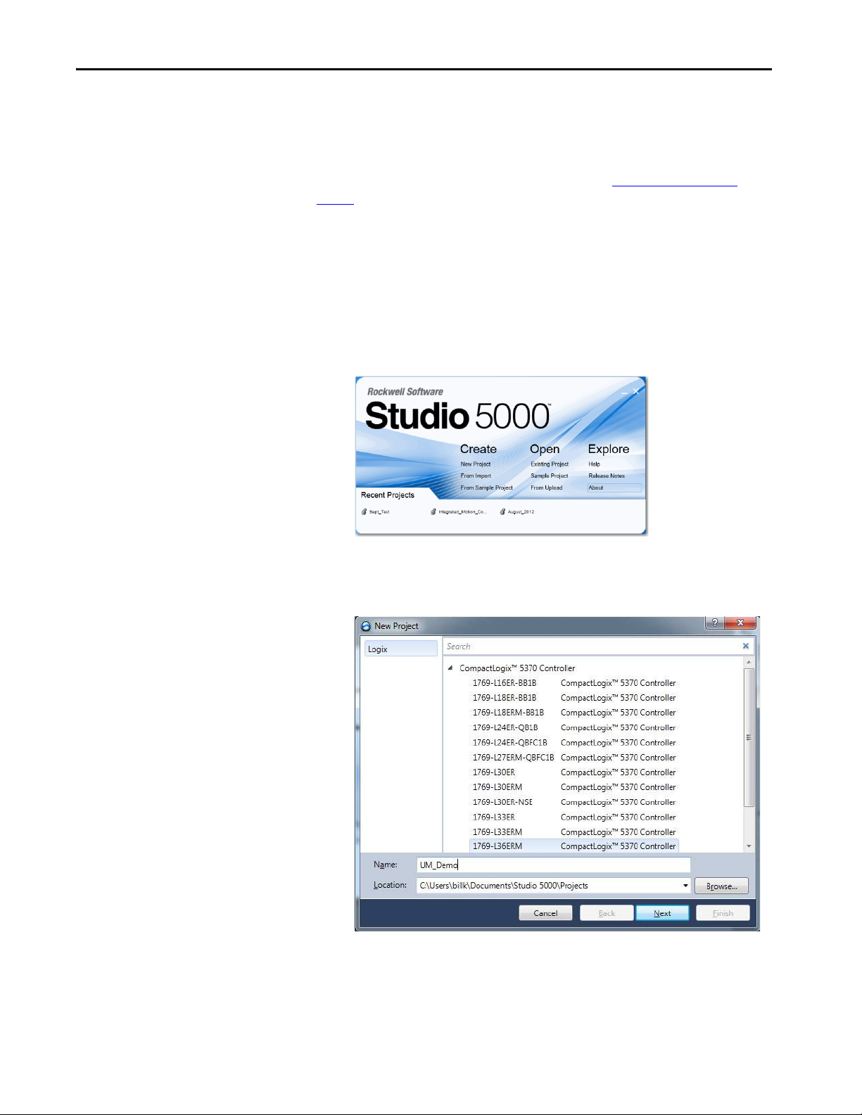
Chapter 5 Configure and Start up the Kinetix 350 Drive System
Configure the Logix5000 EtherNet/IP Controller
This procedure assumes that you have wired your Kinetix 350 drive system and
are using Logix Designer application version 21.00.00 or later.
For help using Logix Designer application as it applies to the configuration of
the ControlLogix® EtherNet/IP controller, refer to Additional Resources
page 9
.
on
Configure the Logix5000 Controller
Follow these steps to configure the Logix5000 controller.
1. Apply power to your Logix5000 controller that contains the EtherNet/
IP port and open your Studio 5000® environment.
2. Click New Project.
The New Project dialog box appears.
3. Select the controller that you are using for your project and click Next.
84 Rockwell Automation Publication 2097-UM002D-EN-P - April 2017
Page 85
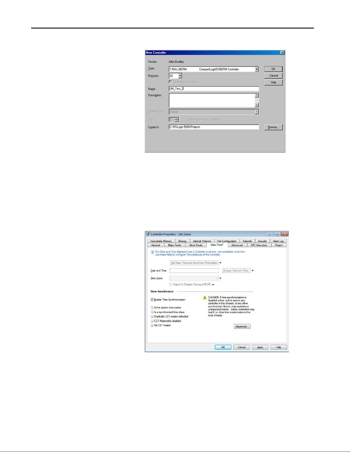
Configure and Start up the Kinetix 350 Drive System Chapter 5
The New Controller dialog box appears.
4. Configure the new controller.
a. From the Type pull-down menu, choose the controller type.
b. From the Revision pull-down menu, choose the revision.
c. Enter the file Name.
5. Click OK.
6. From the Edit menu, choose Controller Properties.
The Controller Properties dialog box appears.
7. Click the Date/Time tab.
8. Check Enable Time Synchronization.
Rockwell Automation Publication 2097-UM002D-EN-P - April 2017 85
Page 86
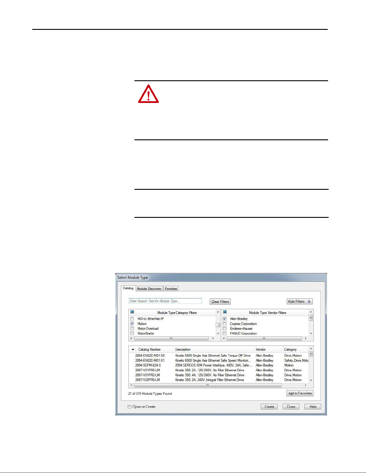
Chapter 5 Configure and Start up the Kinetix 350 Drive System
Configure the Kinetix 350 Drive
Enable Time Synchronization permits the controller to participate in
the ControlLogix Time Synchronization. The controller also
participates in an election in the Logix5000 system for the best
GrandMaster clock.
ATT EN TI ON : Do not change Grand Master clock when motion is active. Time
must be universally understood by all Integrated Motion on the EtherNet/IP
Motion Devices. A change in the wall clock of the Grand Master can introduce
a clock skew between the Integrated Motion on the EtherNet/IP Motion
devices. When clock skew is present the drive can go to sleep, jump, or move
rapidly. Results can be a nuisance motion or motion that can damage
equipment.
9. Click OK.
IMPORTANT To configure Kinetix 350 drive (catalog numbers 2097-V3xPRx-LM) you must
be using RSLogix 5000® software, version 20 or later, or Logix Designer
application.
Follow these steps to configure the Kinetix 350 drive.
1. Right-click the Logix5000 EtherNet/IP controller that you created and
choose New Module.
The Select Module dialog box appears.
2. Clear the Module Type Category Filter and check the Motion category.
86 Rockwell Automation Publication 2097-UM002D-EN-P - April 2017
Page 87
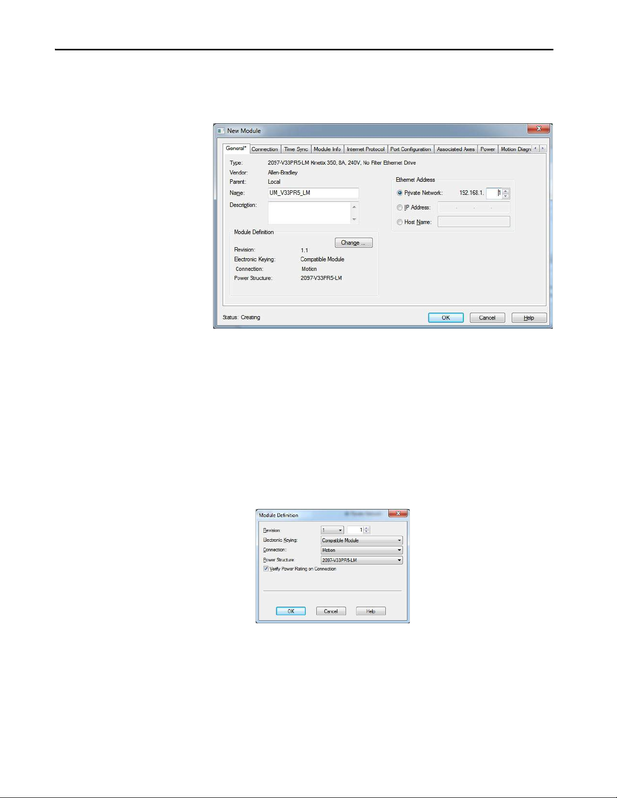
Configure and Start up the Kinetix 350 Drive System Chapter 5
3. Select your 2097-V3xPRx-LM drive as appropriate for your actual
hardware configuration and click Create.
The New Module dialog box appears.
4. Configure the new drive.
a. Enter the drive Name.
b. Click an Ethernet Address option.
In this example, the Private Network address is selected.
c. Enter the address of your EtherNet/IP drive.
In this example, the last octet of the address is 1. This octet must
match the base node address of the drive.
5. Click Change in the Module Definition area.
The Module Definition dialog box appears.
6. From the Power Structure pull-down menu, choose the Bulletin 2097
drive appropriate for your application.
In the example, the 2097-V3xPRx-LM module is chosen.
7. Click OK to close the Module Definition dialog box.
8. Click OK to close the Module Properties dialog box.
Rockwell Automation Publication 2097-UM002D-EN-P - April 2017 87
Page 88

Chapter 5 Configure and Start up the Kinetix 350 Drive System
The 2097-V3xPRx-LM drive appears under the EtherNet/IP module in
the I/O Configuration folder.
9. Right-click the 2097-V3xPRx-LM module that you created and choose
Properties.
The Module Properties dialog box appears.
10. Click the Associated Axes tab.
11. Click New Axis.
The New Tag dialog box appears.
12. Typ e t he ax is Name.
AXIS_CIP_DRIVE is the default Data Type.
13. Click Create.
The new axis (Axis_1) appears under Motion Groups>Ungrouped Axes
in the Controller Organizer and is assigned as Axis 1.
14. Click Apply.
88 Rockwell Automation Publication 2097-UM002D-EN-P - April 2017
Page 89
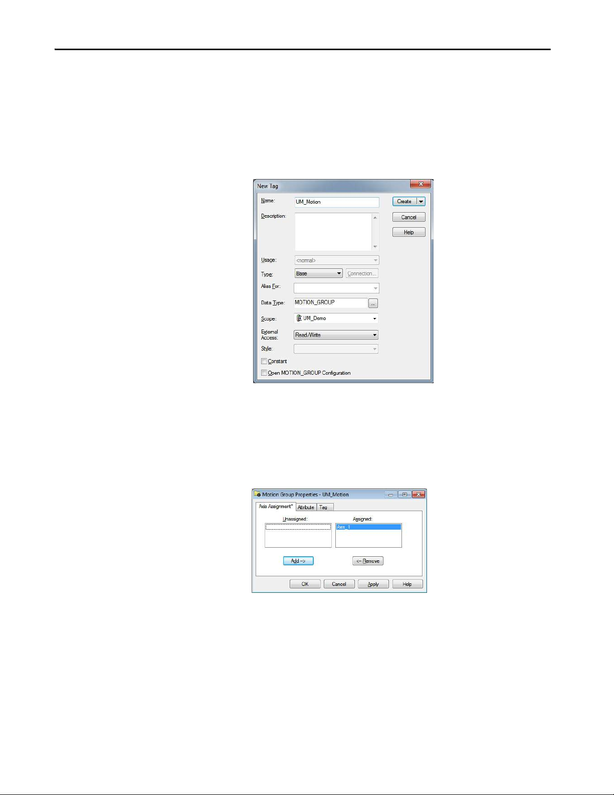
Configure and Start up the Kinetix 350 Drive System Chapter 5
Configure the Motion Group
Follow these steps to configure the motion group.
1. Right-click Motion Groups in the Controller Organizer and choose
New Motion Group.
The New Tag dialog box appears.
2. Type the new motion group Name.
3. Click Create.
The new motion group appears under the Motion Groups folder.
4. Right-click the new motion group and choose Properties.
The Motion Group Properties dialog box appears.
5. Click the Axis Assignment tab and move your axes (created earlier) from
Unassigned to Assigned.
6. Click the Attribute tab and edit the default values as appropriate for
your application.
7. Click OK.
Rockwell Automation Publication 2097-UM002D-EN-P - April 2017 89
Page 90

Chapter 5 Configure and Start up the Kinetix 350 Drive System
Configure Axis Properties
To configure axis properties for your motor or actuator follow these
instructions. If you are using an Integrated Motion Encoder on EtherNet/IP,
catalog number 842E-CM for an axis refer to 842E-CM Integrated Motion
Encoder on EtherNet/IP User Manual, publication 842E-UM002
.
1. Right-click an axis in the Controller Organizer and choose Properties.
2. Click the Motor category.
The Motor Device Specification dialog box appears.
3. From the Data Source pull-down menu, choose Catalog Number.
4. Click Change Catalog.
The Change Catalog Number dialog box appears.
5. Select the motor catalog number appropriate for your application.
To verify the motor catalog number, refer to the motor name plate.
6. Click OK to close the Change Catalog Number dialog box.
90 Rockwell Automation Publication 2097-UM002D-EN-P - April 2017
Page 91

Configure and Start up the Kinetix 350 Drive System Chapter 5
7. Click Apply.
Motor data specific to your motor appears in the Motor category.
8. Click the Scaling category and edit the default values as appropriate for
your application.
9. Click Apply, if you make changes.
10. Click Load category and edit the default values as appropriate for your
application.
11. Click Apply, if you make changes.
12. Click Actions category.
Rockwell Automation Publication 2097-UM002D-EN-P - April 2017 91
Page 92

Chapter 5 Configure and Start up the Kinetix 350 Drive System
The Actions to Take Upon Conditions dialog box appears.
From this dialog box, you can program actions and change the action for
exceptions (faults).
13. Click Parameters.
The Motion Axis Parameters dialog box appears.
From this dialog box, you can set delay times for servo motors. For
recommended motor brake delay times, refer to the Kinetix Motion
Control Selection Guide, publication KNX-SG001
.
14. Click OK.
15. Verify your Logix5000 program and save the file.
92 Rockwell Automation Publication 2097-UM002D-EN-P - April 2017
Page 93

Configure and Start up the Kinetix 350 Drive System Chapter 5
Four Character
Status Indicator
Data Entry Status
Indicator
Download the Program
After completing the Logix5000 configuration, you must download your
program to the Logix5000 processor.
Apply Power to the Kinetix 350 Drive
This procedure assumes that you have wired and configured your Kinetix 350
drive system and your Ethernet/IP interface controller.
SHOCK HAZARD: To avoid hazard of electrical shock, perform all mounting and
wiring of the Bulletin 2097 drive before you apply power. Once power is applied,
connector terminals can have voltage present even when not in use.
Follow these steps to apply power to the Kinetix 350 drive system.
1. Disconnect the load to the motor.
The axis does not operate in position mode during the execution of this
process. Therefore, the position of the axis cannot be guaranteed if the
axis is connected to a vertical load, or the axis is connected to a stored
mechanical energy.
ATT EN TI ON : To avoid personal injury or damage to equipment, disconnect
the load to the motor; including vertical loads. Make sure that each motor is
free of all linkages when you initially apply power to the system.
2. Determine the source of the drive logic power.
If Your Logic Power Then
Is from (24V DC) back-up power Apply (24V DC) back-up power to the drive (BP connector).
Mains input power Apply 120, 240, or 460V AC mains input power to the drive (IPD
connector).
3. Apply 120, 240, or 460V AC mains input power to the Kinetix 350
drive IPD connector.
4. Observe the four-digit status indicator.
If the status indicator is Then
-00- Go to step 5
Blank Return to main step 2
Rockwell Automation Publication 2097-UM002D-EN-P - April 2017 93
Page 94

Chapter 5 Configure and Start up the Kinetix 350 Drive System
5.
If Your Logic Power Then
Is from (24V DC) back-up power
Mains input power Go to step 5
Apply 120, 240, or 460V AC mains input power to the drive
(IPD connector)
6.
If drive ENABLE is Then
Hard wired Apply 24V DC
Not used Disable enableInputChecking by using procedure on
page 100
7. Observe the status indicator on the front of the Kinetix 350 drive.
Status Indicator Condition Status Do This
Module
Axis
Network
Steady green Operational condition Observe the Axis, status indicator page 80
Steady or flashing red Drive is faulted Go to Module State Status Indicator on page79
Steady green or amber, flashing Operational condition Observe the Network, status indicator page 80
Steady or flashing red Axis is faulted Go to Axis State Status Indicator on page 80
Steady green Communication is ready Go to Tes t a nd Tu ne the Ax es
Any state other than steady green Communication error Go to Network State Status Indicator on page 80
on page 94
Test and Tune the Axes
This procedure assumes that you have configured your Kinetix 350 drive, your
ControlLogix EtherNet/IP controller, and applied power to the system. See
Motion System Tuning Application Techniques, publication MOTION-
AT005 for more information on Kinetix servo drive tuning.
.
IMPORTANT Before proceeding with testing and tuning your axes, verify that the drive
status indicators are operating as described in Status Indicators
on page 119
For help using Logix Designer Application as it applies to testing and tuning
your axes with ControlLogix EtherNet/IP controller, refer to Additional
Resources on page 9.
Test the Axes
Follow these steps to test the axes.
1. Verify that the load was removed from each axis.
2. Right-click an axis in your Motion Group folder and choose Properties.
The Axis Properties dialog box appears.
94 Rockwell Automation Publication 2097-UM002D-EN-P - April 2017
Page 95

Configure and Start up the Kinetix 350 Drive System Chapter 5
3. Click Hookup Tests category.
4. Type 2.0 as the number of revolutions for the test or another number
more appropriate for your application.
This Test Performs this Test
Marker
Motor Feedback
Motor and Feedback
Verifies marker detection capability as you rotate the motor
shaft.
Verifies that feedback connections are wired correctly as you
rotate the motor shaft.
Verifies that motor power and feedback connections are wired
correctly as you command the motor to rotate.
5.
If drive ENABLE is Then
Hard wired Apply 24V DC
Not used Disable enableInputChecking by using procedure on page 100
ATT EN TI ON : To avoid personal injury or damage to equipment, apply
only24V ENABLE signal to the axis you are testing.
6. Click the desired tab (Marker/Motor Feedback/Motor and Feedback).
In this example, the Motor and Feedback test is chosen.
7. Click Start.
Rockwell Automation Publication 2097-UM002D-EN-P - April 2017 95
Page 96
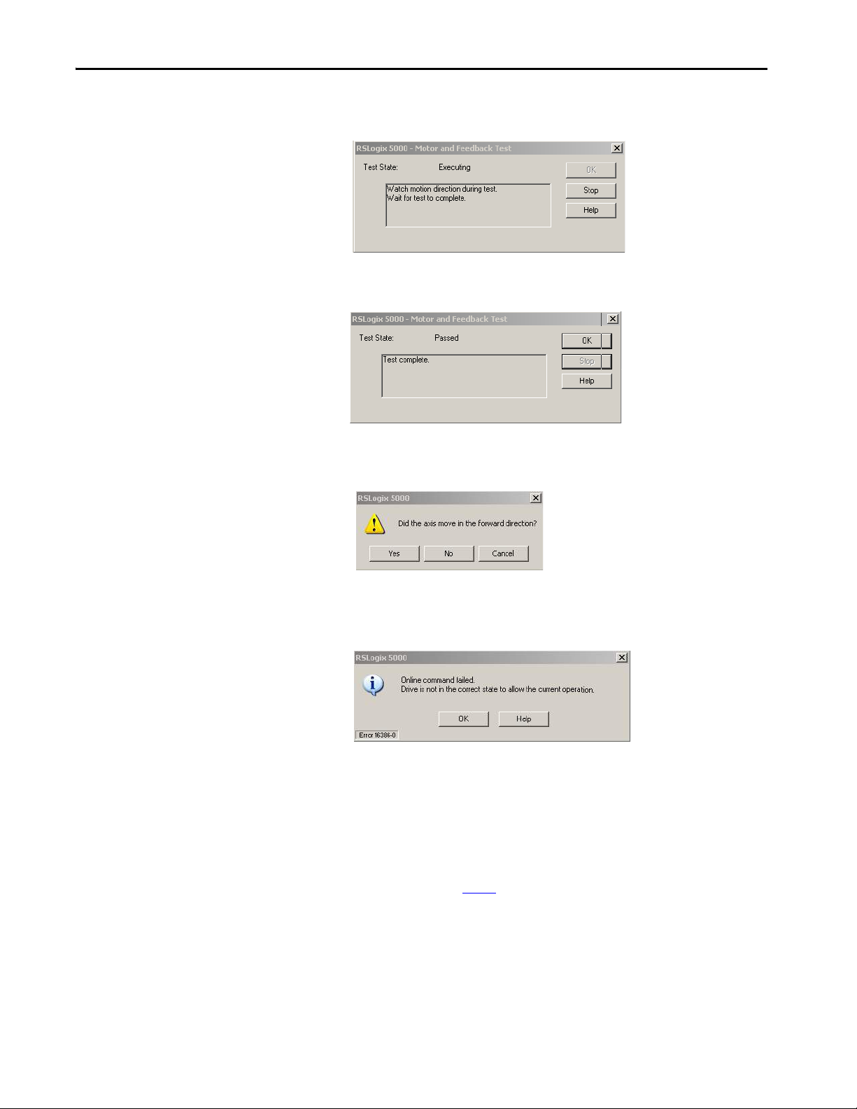
Chapter 5 Configure and Start up the Kinetix 350 Drive System
The RSLogix 5000 - Motor and Feedback Test dialog box appears. The
Test State is Executing.
When the test completes successfully, the Test State changes from
Executing to Passed.
8. Click OK.
This dialog box appears, to confirm that the direction was correct.
9. Click Yes.
If the test fails, this dialog box appears.
a. Click OK.
b. Verify that the Axis status indicator turned solid green during the
test.
c. Verify that the drive ENABLE signal is applied to the axis you are
testing or that the enableInputChecking attribute is set to zero.
d. Verify the unit values that are entered in the Scaling category.
e. Return to main step 6
and run the test again.
96 Rockwell Automation Publication 2097-UM002D-EN-P - April 2017
Page 97
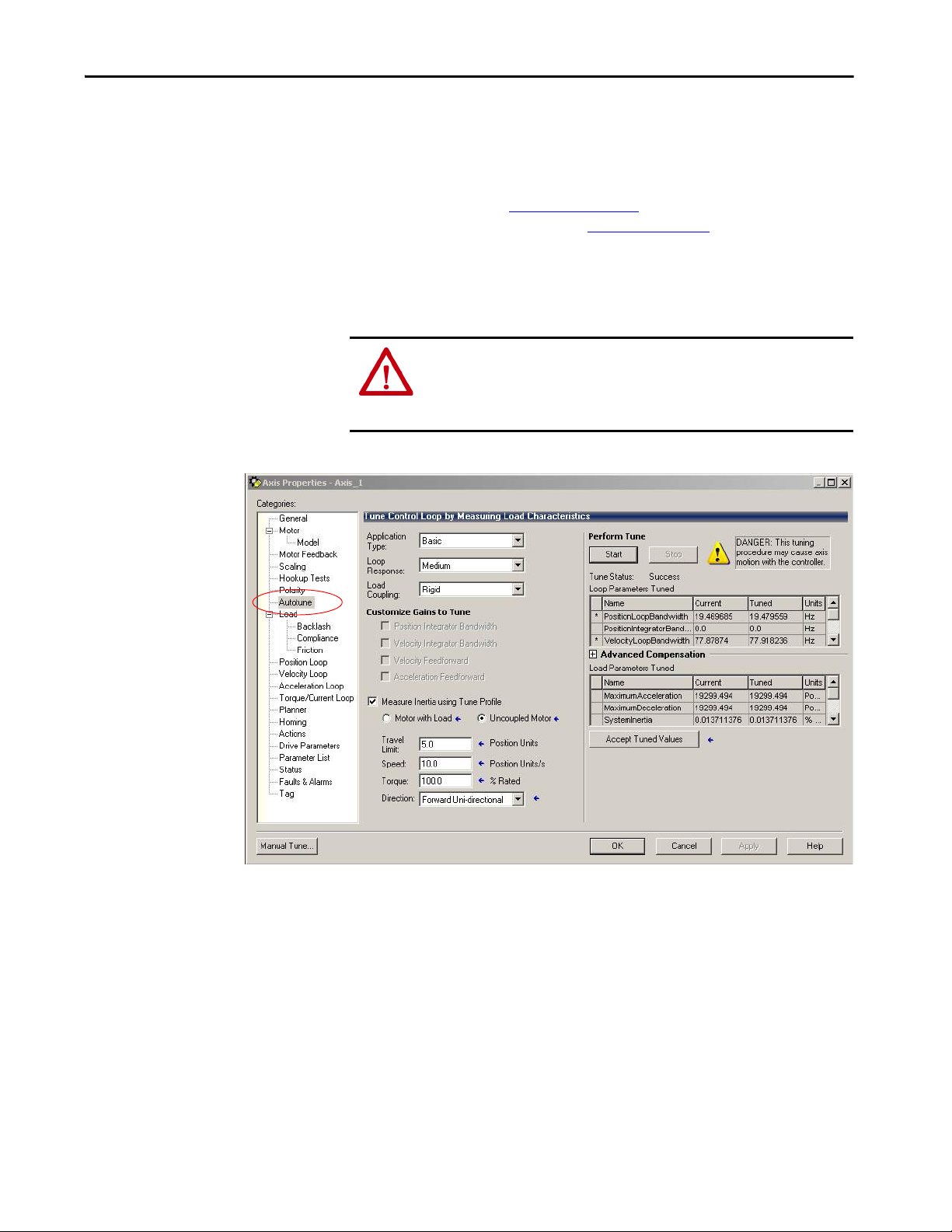
Configure and Start up the Kinetix 350 Drive System Chapter 5
Tune the Axes
The following is a basic procedure for simple systems. If you have a complicated
system, see Integrated Motion on the EtherNet/IP Network: Configuration
and Startup, publication MOTION-UM003
Application Techniques, publication MOTION-AT005
Follow these steps to tune the axes.
1. Verify that the load is still removed from the axis being tuned.
ATT EN TI ON : To reduce the possibility of unpredictable motor response, tune
your motor with the load removed first, including vertical loads, then
reattach the load and perform the tuning procedure again to provide an
accurate operational response
2. Click Autotune category.
and Motion System Tuning
.
3. Type values for Travel Limit and Speed.
In this example, Travel Limit = 5 and Speed = 10. The actual value of
programmed units depends on your application.
4. From the Direction pull-down menu, choose a setting appropriate for
your application.
Forward Uni-directional is default.
5. Edit other fields as appropriate for your application and click Apply.
Rockwell Automation Publication 2097-UM002D-EN-P - April 2017 97
Page 98
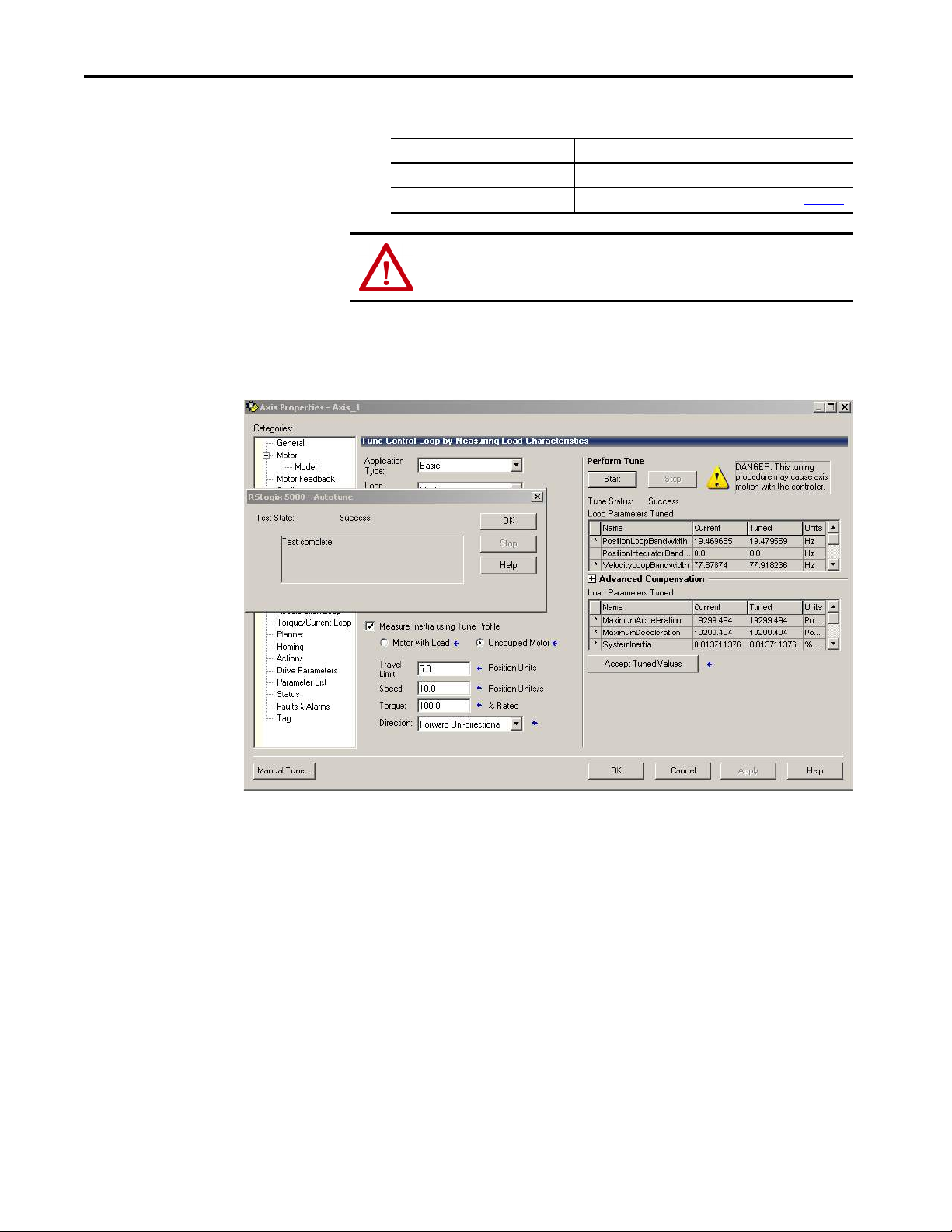
Chapter 5 Configure and Start up the Kinetix 350 Drive System
.
6.
If drive ENABLE is Then
Hard wired Apply 24V DC
Not used Disable enableInputChecking by using procedure on page 100
ATT EN TI ON : To avoid personal injury or damage to equipment, apply only
24V ENABLE signal to the axis you are testing.
7. Click Start.
The RSLogix - Autotune dialog box appears. When the test completes,
the Test State changes from Executing to Success.
Tuned values populate the Loop and Load parameter tables. Actual
bandwidth values (Hz) depend on your application and can require
adjustment once motor and load are connected.
At this point, you can compare existing and tuned values for your gains
and inertias with the prospective tune values.
8. Accept the new values and apply them to the controller.
Now you can run the system with the new gain set and evaluate
performance. You can improve the performance by adjusting application
type, loop response, and/or load coupling selections.
TIP If your application requires stricter performance, you can further improve
performance with manual tuning.
9. Click OK to close the RSLogix 5000 - Autotune dialog box.
10. Click OK to close the Axis Properties dialog box.
98 Rockwell Automation Publication 2097-UM002D-EN-P - April 2017
Page 99

Configure and Start up the Kinetix 350 Drive System Chapter 5
11. If the test fails, this dialog box appears.
a. Click OK.
b. Make motor velocity adjustments.
c. See the appropriate Logix5000 motion module user manual for more
information.
d. Return to step 7
and run the test again.
12. Repeat Test and Tune the Axes
for each axis.
Rockwell Automation Publication 2097-UM002D-EN-P - April 2017 99
Page 100

Chapter 5 Configure and Start up the Kinetix 350 Drive System
Disable EnableInputChecking by Using a Logix Designer Message Instruction
This procedure sends a Logix5000 message to disable the
EnableInputChecking attribute in the Kinetix 350 drive.
1. From the Controller Organizer, choose
Ta s k s > M a i nTa s k > M a i n P r o g r a m > M a i n R o u t i n e .
2. Create an MSG instruction rung as shown.
3. Set the values in the Message Configuration as shown.
4. Click the Communications tab and browse to the drive tag, in this case
K350, as shown.
5. When the program is in Run mode, trigger the rung to run the
instruction.
The drive does not check the enable input signal on IOD-29 Enable to
IOD -26 Common. This MSG instruction is executed only once as it is
a persistent type instruction and gets saved to the drive Non-volatile
Memory. To re-enable the enable input signal checking on IOD-29
Enable to IOD-26 Common, change the Source Element register,
EnableInputChecking from 0 to 1 and trigger the run again.
100 Rockwell Automation Publication 2097-UM002D-EN-P - April 2017
 Loading...