

Page 1

Installation Instructions
Original Instructions
iTRAK 5730 System Starter Kit
Catalog Numbers 2198T-SK-06-05, 2198T-SK-12-10
Topic Page
Product Advisories 2
Open and Inspect the iTRAK 5730 Starter Kit 2
Parts Lists 3
Required Tools 3
Required System Components 3
Product Dimensions 4
Site Requirements 5
Prepare to Lift and Mount the iTRAK 5730 Assembly 5
Mount the iTRAK 5730 Assembly 6
Lift and Mount the iTRAK 5730 Assembly 8
Mount the iTRAK 5730 Starter Kit Power and Control Cabinet 9
Ground Requirements 9
Wire Requirements 9
Wire Diagram 9
Connect the iTRAK 5730 System to the Power and Control Cabinet 11
Lubricate the Track 14
Power and Control Cabinet Controls 14
iTRAK 5730 Starter Kit Configuration 15
Electrical Specifications 24
Environmental Specifications 24
Additional Resources 24
The iTRAK® 5730 Starter kits provide an assembled iTRAK 5730 system and control cabinet ready to help you develop your new machine. The iTRAK 5730 Starter kit is intended for
industrial use only.
Use the instructions in this publication and the iTRAK 5730 System User Manual, publication 2198T-UM003
, to complete the installation and startup of an iTRAK 5730 System Starter
kit. For a complete list of recommended publications, see Additional Resources on page 24.
The iTRAK 5730 System Starter kit was assembled in accordance with the requirements outlined in the iTRAK 5730 System User Manual, publication 2198T-UM003
, and offers Add On
Instructions (AOI) to demonstrate safe torque-off (STO) and Timed SS1 safety functions.These AOIs have been developed for reference only and are not considered as a part of the
product functional safety certification. Therefore, use of any such AOIs are not considered sufficient to achieve risk reduction of hazards identified in the machine risk assessment
without additional measures.For configuration and commissioning of the STO or Timed SS1 safety functions for this purpose, please see the iTRAK 5730 System User Manual,
publication 2198T-UM003
.
Page 2

Product Advisories
Read the following precautions before you begin installation of the product.
Personal Safety
ATTENTION: Only qualified personnel familiar with linear motion equipment and associated machinery should plan or implement the installation, startup,
and subsequent maintenance of the system. Failure to comply can result in personal injury and/or equipment damage.
ATTENTION: Hazardous voltages are present when power is applied to the iTRAK 5730 system. Follow all power supply requirements and complete all
electrical connections as described in these instructions. Operate the equipment within the ratings specified on the iTRAK 5730 system nameplates.
ATTENTION: The movers use strong magnets. There is risk of health hazard for persons with heart pacemakers, metal implants, and hearing aids while in
proximity of magnetic components and the magnetic field produced by components. The magnetic field that is generated can disrupt the functionality of an
automatic implantable cardioverter defibrillator (AICD). People with cardiac pacemakers must not work near the iTRAK 5730 system. Maintenance personnel
must avoid the use of metallic tools and secure items such as badge clips and other personnel effects that could be attracted to the strong magnetic field.
Strong magnets can erase magnetic media. Never let credit cards or electronic media contact or come near the mover or iTRAK 5730 system.
ATTENTION: A hazard of personal injury exists. The movers, which contain application loads, can have high acceleration. Machine guards and safety
enclosures must be implemented to provide protection to personnel.
Product Safety
iTRAK 5730 System Starter Kit Installation Instructions
ATTENTION: Operation of an iTRAK 5730 system must be for its intended use. Instructions for safe installation and operation of the iTRAK 5730 system are in
the iTRAK 5730 System User Manual, publication 2198T-UM003. You are responsible for the product safety of your completed machinery. An incorrectly
applied or installed iTRAK 5730 system can result in component damage or a reduction in product life.
ATTENTION: The iTRAK 5730 system contains electrostatic discharge (ESD) sensitive parts and assemblies. Static control precautions are required when you
install, test, service, or repair this assembly. Component damage can result if ESD control procedures are not followed. If you are not familiar with static
control procedures, reference Guarding Against Electrostatic Damage, publication 8000-4.5.2 or any other applicable ESD protection handbook.
ATTENTION: Operation of the movers with position and motor magnets must be for their intended use. Instructions for safe installation and operation of the
movers with position and motor magnets are in the user manual. You are responsible for the product safety of your completed machinery. An incorrectly
applied or installed mover with position and motor magnets can result in component damage or a reduction in product life.
Open and Inspect the iTRAK 5730 Starter Kit
Remove the Phillips head screws that secure the top and front covers to the crate and remove the covers. If you intend to reuse the shipping crate for storage, retain the covers and
bolts for reuse.
Open the crate and inspect the equipment for damage or missing items. If there is evidence of damage or loss, take the following actions:
• Note on the delivery receipt that the equipment being received is damaged or parts are missing.
• Contact the carrier that made the delivery and schedule an inspection.
• Inform your local Rockwell Automation representative that the equipment is damaged or parts are missing.
• Retain all product packaging for review by the carrier.
For further assistance, contact your Rockwell Automation representative.
The crate can be reused for storage, transport, and shipping.
Product Storage
If you must store the iTRAK 5730 Starter kit before installation, take the following precautions:
• Do not store the equipment outdoors
• Do not store the equipment in a corrosive or humid environment
• If opened, reseal and store the equipment in the shipping container
• Store the equipment in a clean and dry location
Rockwell Automation Publication 2198T-IN002A-EN-P - February 2021 2
Page 3

Parts Lists
Verify the contents of your iTRAK 5730 Starter kit.
iTRAK 5730 System Starter Kit Catalog Number 2198T-SK-06-05
This kit contains these components:
• iTRAK 5730 system - approximate weight 103 kg (227 lb):
• 600 mm straight track
• 5 assembled movers: 2198T-VT0304-E
• 2 metal shipping bars
• Power and control cabinet - approximate weight 86 kg (190.0 lb)
• Compact GuardLogix® controller: 5069-L380ERMS2
• Safety IO: 5069-IB8S, 5069-OBV8S
• iTRAK Power Supply: 2198T-W25-ER
• Kinetix® 5700 DC bus supply: 2198-P031
• Kinetix 5500 line filter: 2198-DB20-F
• Four, 3/8 in. screws and washers
• iTRAK 5730 system power cable, 6 m (19.7 ft): 2198T-CHBFLS8-12AA06
• Ethernet cable, M12 X-code, 5 m (16.4 ft): 1585D-E8TGJM-5
iTRAK 5730 System Starter Kit Installation Instructions
iTRAK 5730 System Starter Kit Catalog Number 2198T-SK-12-10
This kit contains these components:
• iTRAK 5730 system - approximate weight 151 kg (333 lb):
• 1200 mm straight track
• 10 assembled movers: 2198T-VT0304-E
• 2 metal shipping bars
• Power and control cabinet - approximate weight 86 kg (190 lb)
• Compact GuardLogix controller: 5069-L380ERMS2
• Safety IO: 5069-IB8S, 5069-OBV8S
• iTRAK Power Supply: 2198T-W25-ER
• Kinetix 5700 DC bus supply: 2198-P031
• Kinetix 5500 line filter: 2198-DB20-F
• Four, 3/8 in. screws and washers
• iTRAK 5730 system power cable, 6 m (19.7 ft): 2198T-CHBFLS8-12AA06
• Ethernet cable, M12 X-code, 5 m (16.4 ft): 1585D-E8TGJM-5
Required Tools
This table provides a list of the tools that are required to assemble and install an iTRAK 5730 Starter Kit.
Tool Details
Flat-nose screwdriver 3 mm (0.12 in.)
Phillips bit or screwdriver #2
Hexagonal socket 10 mm (for infield covers), 3/8 in. (if the control cabinet is mounted)
Required System Components
These items are not included with the iTRAK 5730 Starter kits and are required for installation:
• A UL rated, 480V AC, 20 A, three-phase input power cable, 10 AWG (6.0 mm2) min.
• Cable (ring) terminals are recommended for termination of the three-phase power cable connections to the circuit breaker (CB1) in the power and control cabinet. See
Wire Requirements on page 9
• M6 x 16 mm lifting hardware is required to lift the iTRAK 5730 assembly into position for mounting.
• Proper lubrication is required to run the system. You can use your own lubrication system or purchase and install the lubrication kit 2198T-AL-SYS-4. See Lubricate the
Track on page 14 for more information.
• To program and start your iTRAK 5730 Starter Kit, use the Studio 5000 Logix Designer® application, version 33 or later. For resources that provide information on how to
configure a Compact GuardLogix controller with the Studio 5000 Logix Designer application, see Additional Resources
for cable (ring) terminal specifications.
on page 24.
Rockwell Automation Publication 2198T-IN002A-EN-P - February 2021 3
Page 4

iTRAK 5730 System Starter Kit Installation Instructions
50.0 mm
(2.0 in.)
386.0 mm
(15.2 in.)
420.0 mm
(16.5 in.)
130.0 mm
(5.1 in.)
350.0 mm
(13.8 in.)
300.0 mm
(11.8 in.)
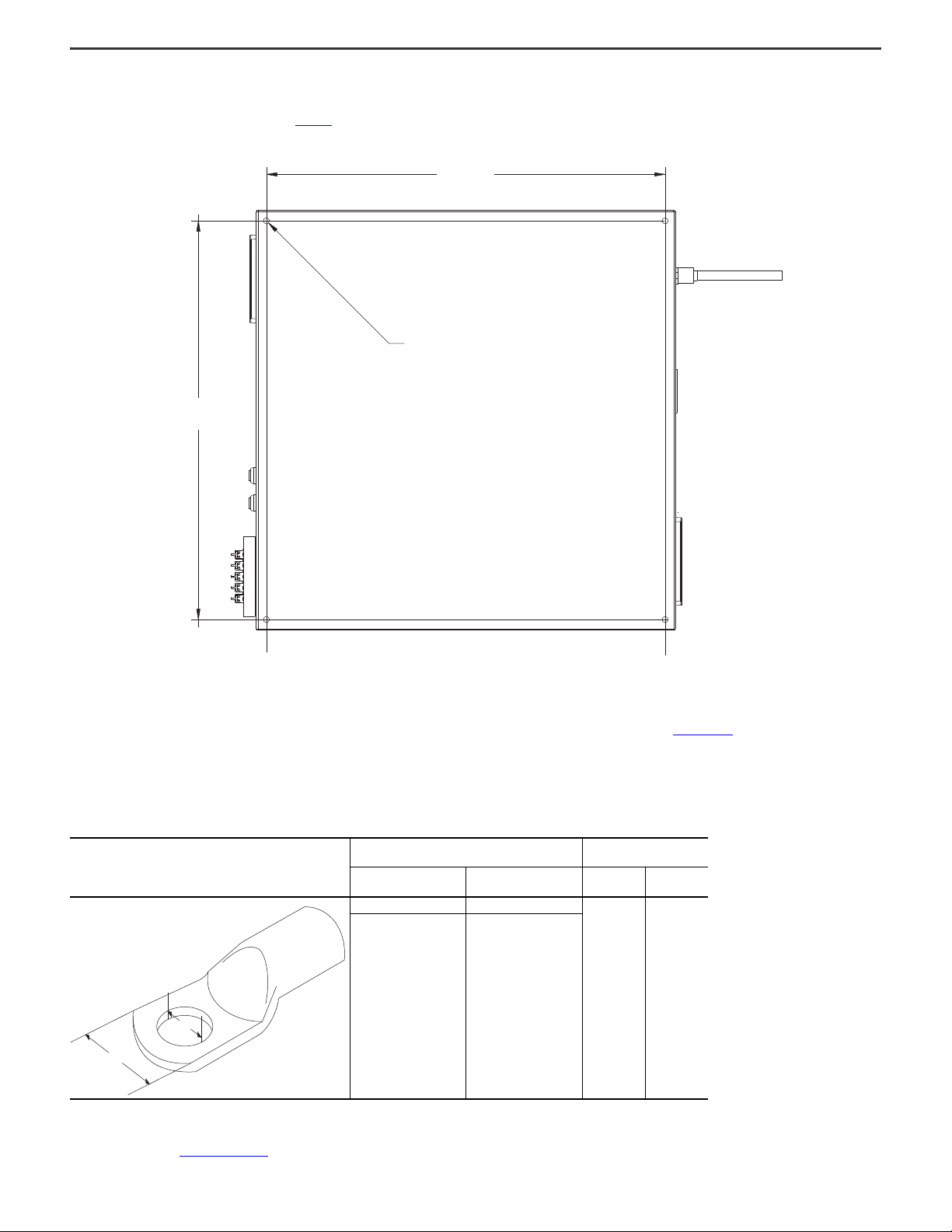
2198T-SK-06-05 iTRAK 5730 Starter kit shown.
762.0 mm
(30.0 in.)
762.0 mm
(30.0 in.)
332.0 mm
(13.0 in.)
Strain-relief Fixture not
Shown for Clarity Only.
Product Dimensions
This section provides approximate dimensions for both of the iTRAK 5730 Starter kits.
Figure 1 - iTRAK 5730 Starter Kit Track with Movers Approximate Dimensions
Figure 2 - iTRAK 5730 Starter Kit Power and Control Cabinet Approximate Dimensions
4 Rockwell Automation Publication 2198T-IN002A-EN-P - February 2021
Page 5

Site Requirements
304.8 mm
(12 in.)
304.8 mm
(12 in.)
Lifting and Mounting Holes Lifting and Mounting Holes
Top Structural Mounting Ring Bottom Structural Mounting Ring
Read the Safety Information section in Chapter 1 of the iTRAK 5730 System User Manual,
publication 2198T-UM003, for important safety and installation guidance information, such
as machine guarding and protection against magnetic and electromagnetic fields. Choose
the location for the iTRAK 5730 Starter kit components installation following the safety
information in the user manual and these considerations:
• Overall finished assembly dimensions
• Operator access to the control panel and E-stop
• Power source location
•Cable lengths
• Objects that can restrict airflow must be a minimum of 304.8 mm (12 in.) away
from the control cabinet side air vents
• Stable and vibration-free surfaces that can support the assembly weight
ATTENTION: Improper use or modification of system components, failure to follow the safety instructions, or disabling safety devices can result in property
damage, injury, electric shock, or death.
Prepare to Lift and Mount the iTRAK 5730 Assembly
Follow these handling and mounting hole use instructions before you attempt to lift, transport, and mount the equipment.
iTRAK 5730 System Starter Kit Installation Instructions
General Handling Instructions
Follow these handling instructions for an iTRAK 5730 assembly:
• Use properly rated equipment and M6 x 16 mm hardware to lift and move the product.
• Qualified professionals must inspect all lifting equipment before it is used to move the product.
• All lifting cables or straps must meet or exceed the maximum weight capacity requirements.
• Wear appropriate personal protection equipment (PPE), including gloves, safety glasses, and safety shoes, when working with kit components and assembling the
product.
ATTENTION: There is a risk of injury by improper handling. You can be injured by being crushed, cut, struck, or sheared while handling and lifting iTRAK 5730
Starter kit components.
Mounting Rings
The structural mounting rings on the iTRAK 5730 assembly contain eight holes each that accept M6 x 16 mm hardware. The mounting ring holes can be used to secure the
appropriate hardware to lift the assembly. The lifting/mounting hole locations are shown in Figure 3. The holes that are used for hardware to lift the assembly are also used for
mounting hardware installation. See Figure 4 on page 6
Figure 3 - Top and Bottom Mounting Ring Lifting and Mounting Holes
for the mounting ring mounting hole patterns.
Rockwell Automation Publication 2198T-IN002A-EN-P - February 2021 5
Page 6

iTRAK 5730 System Starter Kit Installation Instructions
Top Structural Mounting Ring Bottom Structural Mounting Ring
0.00
(0.00)
79.25 (3.12)
115.00
(4.53)
Dimensions are in millimeters and (inches).
62.82 (2.47) REF
0.00 (0.00)
125.00 (4.92)
204.25 (8.04)
0.00
(0.00)
115.00
(4.53)
35.50 (1.40)
62.82 (2.47) REF
0.00 (0.00)
125.00 (4.92)
160.50 (6.32)
Figure 4 - Structural Ring Mounting Hole Pattern
Mount the iTRAK 5730 Assembly
You can mount the iTRAK 5730 assembly to a fixture by using the two metal shipping bars provided in the kit, or by using a customer-sourced mounting system. See the iTRAK 5730
System User Manual, publication 2198T-UM003, for detailed information on how to mount the iTRAK 5730 assembly to a customer-sourced mounting system.
Shipping Bars
Follow these guidelines to install the shipping bars on a mounting surface and to mount the iTRAK 5730 assembly to the shipping bars:
• Secure either of the two holes (through or tapped) on both ends of the shipping bars to a fixture. See Figure 5 on page 7
• Install the shipping bars 104.0 mm (4.1 in.) apart, aligned center-to-center on the mounting holes. See Figure 6 on page 7
• Install the shipping bars with the middle counter-bored holes facing down (away from the iTRAK 5730 assembly).
• Secure the bottom mounting rings of the iTRAK 5730 assembly only to the shipping bars.
• Mount the iTRAK 5730 assembly perpendicular to the shipping bars. See Figure 6 on page 7
.
.
.
6 Rockwell Automation Publication 2198T-IN002A-EN-P - February 2021
Page 7

Figure 5 - Shipping Bar Dimensions
25.4 (1.0)
4 x 12.7 (0.5)
0.0 (0.0)
Dimensions are shown in millimeters and (inches).
2x Ø 6.8 (0.3) Through Hole
(Bar Mount Only)
2x Tap M8 x 1.25 (0.05)
Through Hole (Bar Mount Only)
0.0 (0.0)
7.5 (0 .3)
20.0 (0.8)
16.0 (0.6)
192.5 (7.6)
307.5 (12.1)
480.0 (18.9)
492.5 (19.4)
500.0 (19.7)
2x Ø 6.8 (0.3) Through Hole (iTRAK 5730 Assembly Mount Only)
Ø 11.9 (0.5) 6.5 (0.3)
104.0 mm
(4.1 in.)
Bottom View
Figure 6 - Shipping Bar Installation Dimension
iTRAK 5730 System Starter Kit Installation Instructions
Rockwell Automation Publication 2198T-IN002A-EN-P - February 2021 7
Page 8

iTRAK 5730 System Starter Kit Installation Instructions
B > A
A
B
ɖǥǟʞ
Lift and Mount the iTRAK 5730 Assembly
This table provides the approximate weights of the iTRAK 5730 assemblies:
Kit Cat. No.
2198T-SK-06-05 103 (227)
2198T-SK-12-10 151 (333)
Follow these steps to lift and mount the iTRAK 5730 assembly.
ATTENTION: To guard against possible personal injury and/or equipment damage:
• Qualified professionals must inspect all lifting equipment before it is used to move the product.
• All lifting cables or straps must meet or exceed the maximum weight capacity requirements.
• Inspect all lifting hardware for proper attachment before lifting the equipment.
• Do not subject the equipment to high rates of acceleration or deceleration while transporting to the installation site or when lifting.
• Do not allow personnel or their limbs directly underneath the equipment when it is being lifted and mounted.
1. Remove the Phillips head screws from the top and front covers on the shipping create and remove the covers.
If you want to reuse the shipping crate for storage, retain the covers and hardware for reuse, if not damaged.
2. Install the appropriate lifting hardware in the mounting rings.
• To lift kit catalog number 2198T-SK-06-05, install a minimum of four mounting-ring holes to lift the iTRAK assembly.
• To lift kit catalog number 2198T-SK-12-10, install a minimum of six mounting-ring holes to lift the iTRAK assembly.
3. Connect the appropriate lifting straps to the hardware on the assembly.
Weight
[kg (lb)]
4. Slowly lift and transport the iTRAK 5730 assembly to the installation location.
5. Mount the iTRAK 5730 assembly.
See the iTRAK 5730 System User Manual, publication 2198T-UM003
8 Rockwell Automation Publication 2198T-IN002A-EN-P - February 2021
, for detailed information on how to mount the iTRAK 5730 assembly.
Page 9
iTRAK 5730 System Starter Kit Installation Instructions
724.0 mm
(28.5 in.)
724.0 mm
(28.5 in.)
4x 11.0 mm
(0.4 in.)
Approximate Weight:
86 kg (190 lb)
A
B
Mount the iTRAK 5730 Starter Kit Power and Control Cabinet
The power and control cabinet can be mounted to a panel or be placed on a suitable, stable platform. Mount the power and control cabinet on a panel by using the supplied 3/8 inch
hardware in each of the four mounting holes. See Figure 7 for the power and control cabinet mounting hole dimensions.
Figure 7 - iTRAK 5703 Starter Kit Power and Control Cabinet Mounting Hole Dimensions
Ground Requirements
To reduce the effects of electromagnetic interference (EMI), the iTRAK 5730 assembly and control cabinet must be grounded. The 480V AC input power cable connected to the
control cabinet must be grounded at power source. See ‘Grounding Requirements’ in the iTRAK 5730 System User Manual, publication 2198T-UM003
assembly ground information.
Wire Requirements
Rockwell Automation recommends installation of cable (ring) terminals on the customer-provided power cable. Cable (ring) terminals must meet these specifications:
Cable (Ring) Terminal
Wire Diagram
Use the wire diagram in Figure 8 on page 10 for reference when you complete power, ground, and control power connections.
Cable (Ring) Terminal Dimensions
Width (A)
0.787 in. 0.25 in.
20 mm 6.5 mm
Terminal Hole Diameter
(B)
Cable (Ring) Terminal
Torque
[lb•in] [N•m]
53.0 6.0
, for detailed iTRAK 5730
Rockwell Automation Publication 2198T-IN002A-EN-P - February 2021 9
Page 10

iTRAK 5730 System Starter Kit Installation Instructions
1 2 3 4 5 6 1 2 3 4 E1 E2 E3 E4
10A
OUTPUT MODULE
INPUT MODULE
COMPACTLOGIX
-
5A
343
PE
24C
E5
ETHERNET
SPARE
PE
ENET3
ENET2
OUTPUT A
OUTPUT B
24V
HI
PWR
HI
PWR
24V
iPS1DFE
TO ITRAK
24C
24C
24C
24C
SPARE
24C
SPARE
24 COM
CONT EN-
CONT EN+
DFE
18AWG PE
PE
CUSTOMER SUPPLIED
1L1
1L2
1L3
L2
L3
L1
PE
PE
TB2
24C
PE
PE
PE
SPARE
PE
PE
PE
PE
BLU
BLK
BLU/WHT
GRN/YEL
10AWG
10AWG
18AWG
18AWG
10AWG
10AWG
XLX
+24V
24x 3xx
24 COM, 24C
24C
GROUND STUD ON PLATE
COLOR GAGE WIRE NUMBER
PE
2L1
2L2
2L3
3L1
3L2
3L3
325
248
5L1
5L2
5L3
+24V
24V COM
24C
24C
246SPARE
241
PE
PE
PE
PE
5A
247249
PS1
24V
24V
RET
21
98
-P
031
240245
L1L2L3
4A
5A
iPS1
IN24V+
IN24V+
IN24V-
IN24V-
HIGH
POWER
L1L2L3
PE
341
342
POWER ON
PE
PE
LF1
LINE
LOAD
20A
12
ENET1
ENET4
Logix Controller
SA MOD
-
+
+
-++
-
343
24C
343
24C
5L3
5L2
5L1
F1
3L3
3L2
2L3
2L2
2L1
20A
2L3
2L2
2L1
4L3
4L2
4L1
4L3
4L2
4L1
SR1
440R-D22R2
A1 A2
S11 S21 S12 S22 S32 S42
13 14 23 24S34 L11 Y32 L12
7
TB2
TB3
+24V
SPARE 243
242
2
241
SPARE
41
324
3
TB1
24V COM
+24V +24V AUX
24C
24C
24C
24C
24C
24C 24C
24C
24C
24C
341
242
342
243
406
245
246 246
247
248
401
401
402
403
403
249
405405
406
407
409408
404
407
240
249
+24V
324 325
2198 - 25 -ER
24x
4xx
140M-D8E-C25
100-C23EJ10
1489-M3C040
1606-XLS480E-3
1489-M1C050
1489-M1C050
1489-M1C100
1489-M1C050
CUSTOMER SUPPLIED
2198-DBR20-F
24C
24C
24C
P1
P2
PE
TB4
SPARE
403
409
402
402
404
LA+
LA-
344
24C
344
24C
+24V - TB3
24V COM
24V COM
24V COM
24V COM
+24V - TB3
24V COM
+24V - TB3
+24V - TB3
+24V - TB3
24V COM
+24V - TB3
+24V - TB1
TB1
24V COM
+24V - TB1
+24V - TB1
+24V - TB1
24V COM
24V COM
24V COM
+24V TO SR1
24V TO DFE
+24V TO IPS
+24V TO LOGIX
+24V FROM PS1
+24V TO SR1
+24V TO SW1
+24V TO D1
24V COM TO IPS
24V COM TO DFE
24V COM TO LOGIX
24V COM TO F1
24V COM TO D2
24V COM TO SR1
+24V TO K1
+24V TO F1
TO GROUND STUD
TO DFE
TO LF1 LINE
TO LF1 LOAD
TO ENCLOSURE
TO COVER
TO LOGIX
24V COM TO K1
24V COM TO D3
24V COM TO D1
TO PS1
+24V - TB3
SI-0
SI-0
SR1_S12
DFE_EN-
OFFPAGELEFT-L
DFE_EN+
SO-0P
SO-0P
+24V LA+ 24V
COM LA-
24V COM LA-
+24V LA+
D3
E-STOP LED
CB7
CB2
SW2
RESET
D1
YEL
CB6
D2
WHT
CB4
CB1
CB5
SW2
BLU
CB3
K1
2
143
5
A1
A2
14
6
13
SW1
E-STOP
1
2
4
3
406
404
Figure 8 - iTRAK 5730 System Starter Kit Wiring Diagram
COUPLERS (2)
PANEL MOUNT
3L1
10 Rockwell Automation Publication 2198T-IN002A-EN-P - February 2021
140G-H6C3-C20
24V COM FROM PS1
Page 11

iTRAK 5730 System Starter Kit Installation Instructions
1
7
8
6
2
9
5
3
4
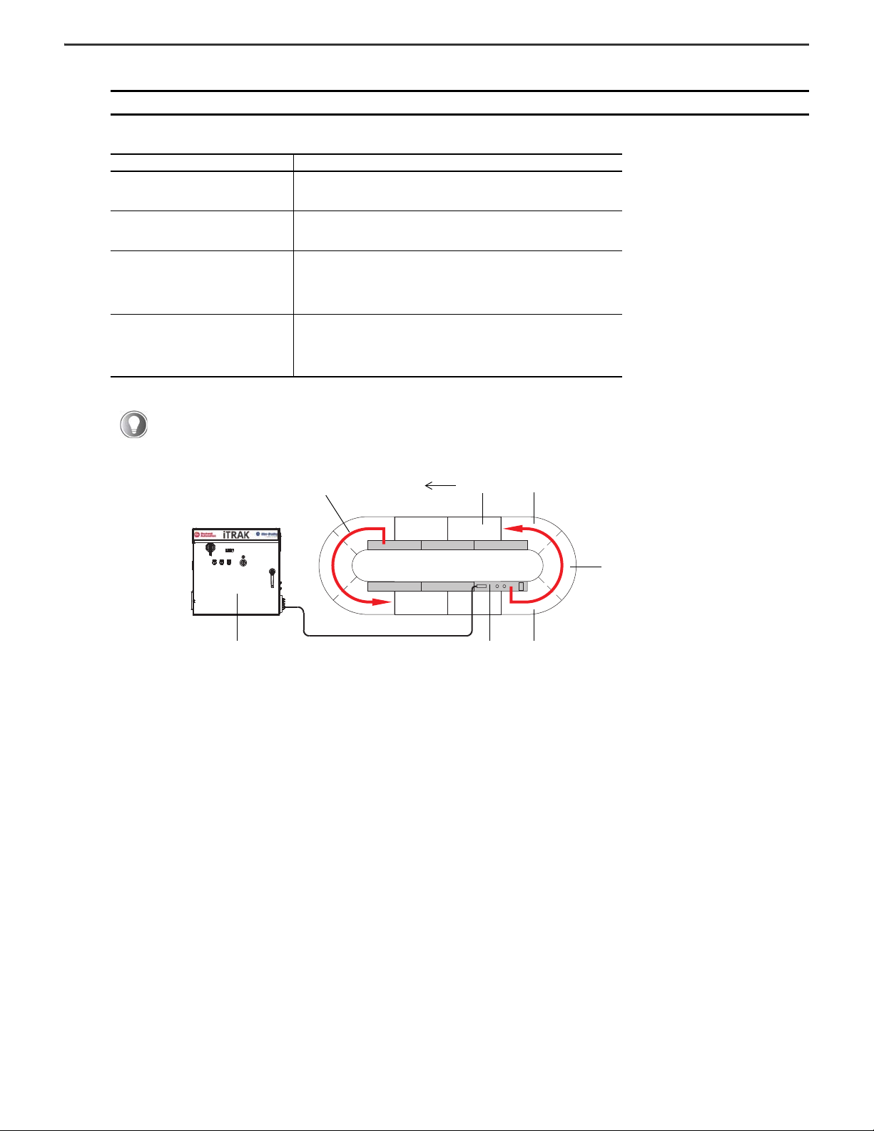
Connect the iTRAK 5730 System to the Power and Control Cabinet
Use this system diagram to understand the system components and connections that are required for the iTRAK 5730 Starter kit.
Item Description Item Description
1
Strain-relief fixture for the 480V AC input power cable
2 iTRAK 5730 Starter kit power and control cabinet 7 Ethernet cable (RJ45 to M12)
3 iTRAK power supply (inside cabinet) 8 Power cable (DC-bus and 24V DC)
4 iTRAK power supply cable clamp (inside cabinet) 9 iTRAK 5730 power and control input connector module
5 Customer-supplied Ethernet cable (RJ45 to RJ45)
(1) In accordance with IEC 60309 series, this fixture provides adequate strain relief and a minimum earthing conductor cross-section of 2.5 mm2 (14 AWG) as part of a multi-conductor
power cable.
Follow these steps to connect the iTRAK 5730 Starter kit track and power and control cabinet.
SHOCK HAZARD: Do not make any cable connections when power is applied to any component in the iTRAK 5730 system. To avoid a shock hazard, verify that
(1)
6 Studio 5000 Logix Designer (not supplied with system)
system power is not applied before you begin this procedure.
1. Verify that power is disconnected from the 480V AC, three-phase power source.
2. Complete these steps on the power and control cabinet.
a. Rotate the main circuit breaker handle to the OFF position.
b. Rotate the door handle clockwise and open the cabinet door.
Rockwell Automation Publication 2198T-IN002A-EN-P - February 2021 11
Page 12

iTRAK 5730 System Starter Kit Installation Instructions
4
2
1
CB1
3
2 1
1
2
2198T-W25K-ER iTRAK Power Supply (bottom view)
Front of Po wer
Supply
3. To connect the 480V AC three-phase power cable to the main circuit breaker (CB1), complete these steps.
a. Feed the power cable through the strain-relief fixture on the upper, left side of the cabinet.
b. Install cable (ring) terminals on the individual wires of the three-phase power cable.
c. Remove the Phillips head screw and cover from the top of the circuit breaker (CB1) in the control cabinet.
d. Secure the three-phase power wires to the input terminals (L1, L2, L3) on the circuit breaker. Apply final torque: 6 N•m (53 lb•in).
e. Connect and secure the power ground cable to the PE stud with the nut provided. Apply final torque: 6 N•m (53 lb•in).
Item Description Item Description
1 Customer-provided 480V AC power cable 3 PE ground stud
2 Strain-relief fixture 4 CB1 input terminals (L1, L2, L3)
f. Re-install the cover on the circuit breaker.
4. To connect the power and control cable to the iTRAK power supply, complete these steps.
a. Verify that a small portion of the cable jacket has been removed to expose the shield braid.
b. On the right side of the cabinet, insert the loose leads on the iTRAK power cable through the gland.
c. Connect the leads of the iTRAK power cable to the 24V DC (ICP) and DC-bus (IDC) connectors on the bottom of the iTRAK power supply.
Item Description
1 24V iTRAK control power
2DC-bus output power
Connects to Terminals (Output A)
Pin Signal
ICP-1
ICP-2
IDC-4
IDC-3
IDC-2
IDC-1
24V+
24V–
GND
H
L
DC-
Wire Color
Red
White
Green/Yellow
Brown
Black
Blue
Wire Size
mm² (AWG)
1.5…6
(16…10)
2.5…6.0
(12…10)
Strip Length
mm (in.)
10.0 (0.39)
10.0 (0.39)
Torque Value
N•m (lb•in)
0.7…0.8
(6.1…7.0)
0.7…0.8
(6.1…7.0)
12 Rockwell Automation Publication 2198T-IN002A-EN-P - February 2021
Page 13

iTRAK 5730 System Starter Kit Installation Instructions
iTRAK Power Supply
Cable Clamp
Power Input Connector Cover
Ethernet Port Cover
5. To terminate the cable shields to the ground clamp on the bottom of the iTRAK power supply, complete these steps.
a. Loosen the clamp knob.
b. Position the exposed portion of each cable braid directly in line with the clamp.
c. Finger-tighten the clamp knob.
The cable must not move within the clamp under its own weight or when slight pressure is applied by hand.
6. To connect the iTRAK power cable to the iTRAK power and control input connector module, complete these steps.
a. Use a 10 mm hexagonal socket bit to remove the M6 x 35 mm hex head bolts that secure the infield covers to the iTRAK assembly. Reassembly torque: 4.5 N•m (40.0
lb•in).
b. On the iTRAK power and control input connector module, remove the protective cap from the power input connector and the Link 0 Ethernet port.
Rockwell Automation Publication 2198T-IN002A-EN-P - February 2021 13
Page 14

iTRAK 5730 System Starter Kit Installation Instructions
Connector Module Ethernet Port Connector
Ethernet Cable M12 Connector
1
34 5 62
c. Verify that the iTRAK power cable connector outer-housing is in the unlocked position.
d. Align the arrow on the cable connector with the arrow on the power input connector on the connector module.
e. Insert the cable connector into the motor power connector on the connector module until it is fully seated.
f. Rotate the cable connector outer housing to the locked position.
7. Connect the RJ45 Ethernet connector on the Ethernet cable to a port on the power and control cabinet.
8. Complete these steps on the iTRAK power and control input connector module.
a. Verify that the connector pins are aligned and insert the Ethernet cable M12 connector into the Ethernet connector on the connector module.
b. By turning the cable outer housing clockwise, secure the cable to the connector module mounting ring until the cable is fully seated.
9. Connect the 480V AC input power cable to the grounded power source.
Lubricate the Track
We recommend that you apply a lubricant (such as Kluber 4 UH1-68N) to the track system before putting the iTRAK 5730 assembly into service. You can purchase and install the
iTRAK 5730 lubrication system, catalog number 2198T-AL-SYS-4 for automated track lubrication. The lubrication system requires a 24V DC power source and can be connected to
the 24V I/O port on the Logix controller in the power and control cabinet. See the iTRAK 5730 System User Manual, publication 2198T-UM003, for details.
Power and Control Cabinet Controls
Figure 9 provides identification and descriptions of the controls and indicator lights on the power and control cabinet.
Figure 9 - iTRAK Power and Control Cabinet Controls
Item Description Item Description
1 Main circuit breaker 4 Reset
2 24V DC power indicator light (yellow) 5 E-stop
3 480V AC power indicator light (white) 6 Mechanical, lockable handle
14 Rockwell Automation Publication 2198T-IN002A-EN-P - February 2021
Page 15

iTRAK 5730 System Starter Kit Installation Instructions
1
2
3
4
5
iTRAK 5730 Starter Kit Configuration
Each iTRAK 5730 Starter kit includes two pre-configured Studio Logix Designer project (*.acd) files, which allow you to startup of the system out-of-the-box. This section provides
information about the iTRAK 5730 Starter kit project file configuration. For details on how to configure an iTRAK 5730 system, see the iTRAK 5730 System User Manual, publication
2198T-UM003.
To view the configuration of your iTRAK Starter kit, open the appropriate file for your track catalog number: 2198T-SK-06-05.acd or 2198T-SK-12-10.acd. The images in this section
represent starter kit 2198T-SK-06-05.acd file.
Project File Structure
The project files have the following are structure:
Item Description
1 File name.
Event task. The Motion Group Execution triggers the event task, which contains the Device Handler for the iTRAK
2
5730. See Device Handler for iTRAK 5730 for details.
8 ms periodic task. The 8 ms task contains the following two programs:
• P01_iTRAK_Management - This program contains routines to monitor the status of the Device Handler and the
iTRAK 5730 hardware, and startup, shutdown, clear fault, and tuning sequence.
3
• P02_iTRAK_Motion - This program contains different motion sequences including:
– Simple moves, such as jogging and homing movers
– Advanced motion, such as station programming which includes built-in collision avoidance.
256 ms periodic task. The 256 ms task contains the raM_Dvc_DHLP_iTRAK5730 program. This program is a
4
language pack, which can be used to choose the language in which all the messages (like faults, alarms, etc.) are
displayed. The starter kit code contains the English Language pack only.
Safety task. The Safety task contains a routine that enables the safe torque-off function on all the motor modules
5
when an E-stop is enabled.
Device Handler for iTRAK 5730
The iTRAK 5730 device handler is a library set for interaction with the Rockwell Automation iTRAK 5730. The device handler provides powerful tools for device diagnostics and
management. The device handler consists of a program paired with associated data structures that synchronizes the physical movers with path axes. The device handler provides:
• A basic instruction set for commissioning and enabling the iTRAK 5730.
• A set of instructions for basic operation of the iTRAK 5730, such as energize/de-energize, clear faults, etc.
• An architecture for virtual or physical operation of the iTRAK 5730.
• Enhanced management of the track as well as individual movers in the form of axes with the following features:
• Text-based status and diagnostics
•Faceplate
• Error management
• Multilingual support for diagnostics messages.
Rockwell Automation Publication 2198T-IN002A-EN-P - February 2021 15
Page 16

iTRAK 5730 System Starter Kit Installation Instructions
Hardware Component IP Address Assignments
This table lists the hardware components included in the kits and the assigned IP
address (if applicable).
Hardware Component Catalog Number Qty. IP Address
Compact GuardLogix controller 5069-L380ERMS2 1 192.160.1.100
Safety input module 5069-IB8S 1 —
Safety output module 5069-OBV8S 1 —
Kinetix 5700 DC bus supply 2198-P031 1 192.168.1.10
iTRAK power supply 2198T-W25-ER 1 192.168.1.11
Kinetix 5500 line filter 2198-DB20-F 1 —
Motor module section
Motor module section
iTRAK 5730 starter
kit 2198T-SK-06-05
iTRAK 5730 starter
kit 2198T-SK-12-10
10 192.168.1.20…192.168.1.29
14 192.168.1.20…192.168.1.33
Axis and Hardware Component Configuration
Each mover and motor module section is represented as a CIP axis in the Motion Group.
Figure 10 is an example of the 2198T-SK-06-05 starter kit I/O configuration tree. The
mover CIP axes are represented by CIPMover_nn in Figure 10. The motor module
section CIP axes are represented by CIPSection_nn in Figure 10
Each mover is also associated with a corresponding virtual axis (represented by
Mover_nn in Figure 10
). The virtual axes are used when you need to run a simulation
without the physical movers. The virtual axes are also used to command the physical
movers by linking the CIP Mover axis to the virtual mover axis.
.
Figure 10 - 2198T-SK-06-05 iTRAK 5730 Starter Kit I/O Configuration Tree
2198T-SK-06-05 Starter Kit
There are 10 motor module section axes in the I/O configuration tree. The
2198T-SK-06-05 starter kit is comprised of four 600 mm straight motor modules (two
on each side of the track) and two curved motor modules. Each curved motor module
is internally comprised of three motor sections. There are five mover axes in the I/O
configuration tree.
2198T-SK-12-10 Starter Kit
There are 14 motor module section axes in the I/O configuration tree. The
2198T-SK-06-05 starter kit is comprised of eight 600 mm straight motor modules (four
on each side of the track) and two curved motor modules. Each curved motor module
is internally comprised of three motor sections. There are 10 mover axes in the I/O
configuration tree.
16 Rockwell Automation Publication 2198T-IN002A-EN-P - February 2021
Page 17

iTRAK 5730 System Starter Kit Installation Instructions
Mover CIP Axes Configuration
This section describes how the mover CIP axes are configured.
Each straight motor module is 300 mm long and each curved module has an arc length of 900 mm (300 mm for each motor module in the curve). The Unwind value for each mover
CIP axis is set to the total length of the track.
Follow these steps to view the mover CIP axes configuration.
1. In the Controller Organizer, right-click the CIPMover_nn axis and choose Properties.
The Properties dialog box appears.
2. Select the Scaling category.
3. The Unwind value is set to the total length of the track (in millimeters). 3000 mm in this example for starter kit 2198T-SK-06-05.
4. The Mode is set to ‘Cyclic,’ identifying a closed loop track.
Rockwell Automation Publication 2198T-IN002A-EN-P - February 2021 17
Page 18

iTRAK 5730 System Starter Kit Installation Instructions
Motor Module Section CIP Axes Configuration
This section describes how the motor module section CIP axes are configured.
Follow these steps to configure the motor module section CIP axes.
1. In the Controller Organizer, right-click the CIPSection_nn axis and choose Properties.
The Properties dialog box appears.
2. Expand Motion and select the Associated Axes Category.
For each iTRAK 5730 motor module, five axes are possible; one section axis and up to four mover axes.
• Axis 1 is the section axis.
• Axis 2…Axis 5 are the mover axes.
3. Select the Track Configuration category.
4. The Track ID is set to ‘1.’
The iTRAK 5730 Starter kits can support one track ID only. When multiple tracks are configured, choose the track ID from the Track ID pull-down
menu.
18 Rockwell Automation Publication 2198T-IN002A-EN-P - February 2021
Page 19
5. The Mover Axis Assignment Sequence is set to ‘Decreasing Position from Reference Mover.’
Power and Control Input Connector Module Section 0Power and Control Cabinet
Section 1
Section 2Section n
Power Flow
IMPORTANT All motor module section axes must be configured with the same Mover Axis Assignment Sequence.
Available options include:
Mover Axis Assignment Sequence Description
Decreasing Position
Increasing Position
Decreasing Position from Reference Mover
Increasing Position from Reference Mover
Based on the Mover Axis Assignment Sequence, the track assigns mover IDs as follows:
• Mover 0 is the mover associated with Axis 2 (Mover) of section 0 of the track. Section 0 is the motor module section to which the power and control
input connector module is connected (see illustration). Section 0 is assigned the IP address 192.168.1.20 and is associated with the CIPSection_00 axis.
Mover 0 is defined based on the Mover Axis Assignment Sequence chosen. In the starter kit code, the reference mover is Mover 0 and is associated with
the CIPMover_00 axis.
The motor module assigns movers on the track as decreasing sequential axis instances.
The mover with the highest position value is the first mover, followed by movers with
decreasing position values.
The motor module assigns movers on the track as increasing sequential axis instances.
The mover with the lowest position value is the first mover, followed by movers with
increasing position values.
The motor module assigns movers on the track as decreasing sequential axis instances
based on the mover identified as the “Reference Mover.’ The ‘Reference Mover’ is the first
mover, followed by movers of decreasing position values relative to the ‘Reference
Mover.’ A south pole position magnet (with the black anodized surface finish) installed on a
mover electrically identifies the ‘Reference Mover.’
The motor module assigns movers on the track as increasing sequential axis instances
based on the mover identified as the ‘Reference Mover.” The ‘Reference Mover’ is the first
mover, followed by movers of increasing pos ition values relative to the ‘Reference Mover.’
A south pole position magnet (with the black anodized surface finish) installed on a mover
electrically identifies the ‘Reference Mover.’
iTRAK 5730 System Starter Kit Installation Instructions
• Other movers (if any) associated with the section 0 are assigned successive mover IDs. (mover 1 is Axis 3, and so on).
• If there are no movers associated with the section axes other than Axis 2, then the mover associated with Axis 2 of section 1 is assigned mover 1, and
so on. Section 1 is the section next to section 0 in the counterclockwise direction. Section 1 is assigned the IP address 192.168.1.21 and is associated with
the CIPSection_01 axis. Mover 1 is next to the reference mover, has a smaller position value, and is associated with the CIPMover_01 axis.
Rockwell Automation Publication 2198T-IN002A-EN-P - February 2021 19
Page 20

iTRAK 5730 System Starter Kit Installation Instructions
Section A
Section B
Section C
Top View
6. Section Motor defines the type of motor module section assigned to the motor module section CIP axis.
IMPORTANT A curved motor module is comprised of three individual sections: curve section A, curve section B, and curve section C.
Each of the three curve sections needs to be added as a separate motor module and configured individually.
• If your motor module is a straight section, select 2198T-L20-T0303-A00-S2
• If your motor module is a curve section A, select 2198T-L20-T0309-D18-S2-A
• If your motor module is a curve section B, select 2198T-L20-T0309-D18-S2-B
• If your motor module is a curve section C, select 2198T-L20-T0309-D18-S2-C
7. Motor Mover is set to 2198T-VT0304-E. This is the only valid option.
8. The Track Length field is set to the total length of the track (in meters).
The Length parameter of the CIPMover_nn axes associated with this section axis is automatically updated in the Motor Feedback
section based on the Track Length parameter value for the section axis.
Download the Program and Start the Controller
Follow these steps to download project file to the controller and start the iTRAK system.
1. Apply power to the system.
2. In Studio 5000 Logix Designer, connect to the controller and download the project file.
3. Set the controller to Remote Run mode.
4. Expand ms0008p10 (8 ms task) and P01_iTRAK_Management and open R01_iTRAK_DeviceStatus.
20 Rockwell Automation Publication 2198T-IN002A-EN-P - February 2021
Page 21

5. Verify that the Sts_Physical, Sts_Connected and Sts_Idle outputs are set.
The Device Status is an Add On Instruction (AOI) to view the status of the Device Handler and the hardware.
Parameter Description
Sts_Physical The iTRAK is in physical operation.
Sts_Connected All the hardware is communicating with the controller and the Motion Group is synced.
Sts_Idle The Device Handler is connected and is waiting for the user to apply the track configuration.
6. To initiate the startup sequence, access the R02_iTRAK_Sequence routine and enable Cmd_Startup bit in rung 0.
iTRAK 5730 System Starter Kit Installation Instructions
The startup sequence configures the track and energizes the motor module sections and movers. A successful startup enables the track for motion.
7. To check if the routine completed successfully, verify that the bStartupCompleted bit is latched and the nStartSeq tag value is set to 999.
Rockwell Automation Publication 2198T-IN002A-EN-P - February 2021 21
Page 22
iTRAK 5730 System Starter Kit Installation Instructions
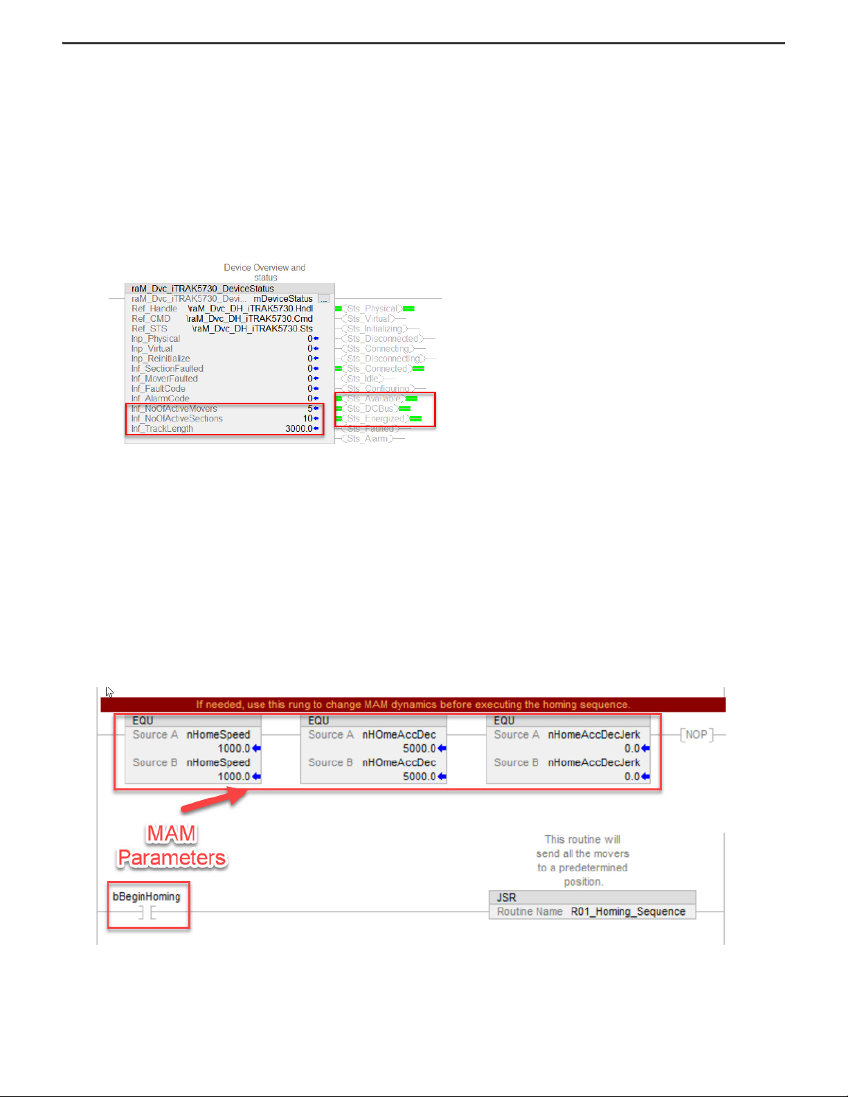
8. Expand ms0008p10 (8 ms task) and P01_iTRAK_Management and open R01_iTRAK_DeviceStatus.
9. Verify that the Sts_Available, Sts_DCBus and Sts_Energized outputs are set.
10. Verify the following:
For a 2198T-SK-06-05 starter kit:
• The number of active movers (Inf_ActiveMovers tag) is 5
• The number of active sections (Inf_ActiveSections tag) is 10
• The track length (Inf_TrackLength tab) is 3000 (mm)
For a 2198T-SK-12-10 starter kit:
• The number of active movers (Inf_ActiveMovers tag) is 10
• The number of active sections (Inf_ActiveSections tag) is 14
• The track length (Inf_TrackLength tag) is 4200 (mm)
Motion Profiles
There are three types of motion profiles included in the iTRAK 5730 Starter kit code.
• Two of the profiles provide basic homing and jogging moves.
• A third profile uses multiple station AOIs to send vehicles to target positions that simulate process station locations. These AOIs include collision avoidance built into the
algorithm that controls adjacent movers so that they do not collide when moving between stations.
The code simulates two process zones:
• The first zone is a one-up process station, where one mover stops for 400 ms and then exits the station.
• The second zone is a two-up station, where two movers stop simultaneously for 800 ms with a pitch of 200 mm.
All three move profiles can be enabled from the Main Routine (ms0008p10 > P02_iTRAK_Motion > R00_Main_Routine).
The main routine can also be used to change the move parameters for the homing and jogging sequence. To start the main routine, toggle the appropriate tag in the same rung as
the JSR. For example, to start the homing sequence, toggle bBeginHoming to start the R01_Homing_Sequence routine.
22 Rockwell Automation Publication 2198T-IN002A-EN-P - February 2021
Page 23
iTRAK 5730 System Starter Kit Installation Instructions
In many cases the application involves repetitive logic for all the movers/axes. In such cases commands, checks based on positions, dynamics, and the state of each mover is
implemented easily in loops. To illustrate this, the jog sequence is implemented by using both ladder logic and structured text. We encourage you to implement your application in
whichever language with which you are comfortable and/or proficient. The ICT libraries work well in both Ladder Logic and Structured Text. Set the bUseST bit to run the structured
text routine R03_Jog_Sequence_ST and reset this bit to run the ladder logic routine R02_Jog_Sequence.
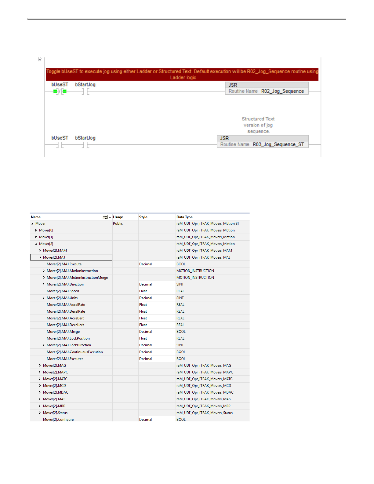
Mover Interface for the iTRAK 5730 System
The Mover array is a User Defined Data Type that is used by the Device Handler to access motion instructions for the iTRAK 5730 system from one public interface. A public
parameter is part of the Device Handler program (raM_Dvc_DH_iTRAK5730). A public parameter can be accessed by other programs, as opposed to a local parameter which can only
be accessed by routines in which the tag is defined. The public parameter is accessed by other programs using the notation \[ProgramName].TagName. For example, to access the
Mover array the notation will be .\raM_Dvc_DH_iTRAK.Mover5730[i] where i is the ith mover. Open the Device Handler program and explore the Mover array.
Rockwell Automation Publication 2198T-IN002A-EN-P - February 2021 23
Page 24

iTRAK 5730 System Starter Kit Installation Instructions
Each mover array has motion instructions like MAJ, MAG, MAPC, etc. The motion interface contains all the parameters associated with a particular motion instruction. For example, in
this image the MAJ structure contains members that are present in a standard MAJ motion instruction block in Studio 5000. All axis feedback and status are consolidated in the
Mover array. To jog a mover, populate the MAJ motion instruction interface for the appropriate mover and then enable the Execute bit. There is an Execute bit for each motion
instruction in the Mover array. When a Device Handler is instantiated, all parameters are set to 0.
The station routines (R04_Station_01, R05_Station_02, and R06_Station_03) have the station AOIs which define the position of the station, station ID, and parameters, which define
the move when movers exit the station. These parameters include velocity, acceleration, deceleration, jerk, and minimum pitch between movers. The routine contains logic that
simulates vehicles stopping for a specific amount of time and sending them to the next station.
For information on the iTRAK device handler and the associated AOIs, see the documentation in the Independent Cart Technology libraries package available in the Product
Compatibility and Download Center website, rok.auto/pcdc
.
Electrical Specifications
Category Specification
Electrical rating 480V AC, 16 A, 50/60 Hz
Short circuit rating 10 kA
Electrical system TN-C
Environmental Specifications
Category Specification
Environmental compliance Rockwell Automation maintains current product environmental information on its website at: https://rok.auto/certifications
IP rating IP22, Type 1
Ambient operating temperature 5 °C (41 ° F)…40 °C (104 ° F)
Altitude Up to 1000 m (3281 ft)
Relative humidity Less than 50% at 40 °C (104 ° F)
Transportation and storage temperature -25…+55 °C (-13…+131 °F)
Additional Resources
These documents contain additional information concerning related products from Rockwell Automation.
Resource Description
iTRAK 5730 System User Manual, publication 2198T-UM003
iTRAK 5730 System Technical Data, publication 2198T-TD002
Kinetix® Servo Drives Specifications Technical Data, publication KNX-TD003
Kinetix 5700 iTRAK Power Supply and iTRAK Bus Conditioner Module Supply Installation
Instruction, publication 2198T-IN001
Independent Cart Technology Libraries, available on the Product Compatibility and
Download Center website, rok.auto/pcdc
GuardLogix 5580 and Compact GuardLogix 5380 Controller Systems Safety Reference
Manual, publication 1756-RM012
Compact GuardLogix 5380 Controllers User Manual, publication 5069-UM001
EtherNet/IP Network Devices User Manual, ENET-UM006
Ethernet Reference Manual, ENET-RM002
System Security Design Guidelines Reference Manual, SECURE-RM001
Industrial Components Preventive Maintenance, Enclosures, and Contact Ratings
Specifications, publication IC-TD002
Safety Guidelines for the Application, Installation, and Maintenance of Solid-State Control,
publication SGI-1.1
Industrial Automation Wiring and Grounding Guidelines, publication 1770-4.1
Product Certifications website, rok.auto/certifications
You can view or download publications at rok.auto/literature
. Provides declarations of conformity, certificates, and other certification details.
.
Provides information and instructions for how to assemble, lift, mount, connect, configure, troubleshoot, and
maintain an iTRAK 5730 system.
Product specifications for Rockwell Automation iTRAK 5730 system components, with performance,
environmental, certifications, load force, and dimension drawings.
Product specifications for Kinetix Integrated Motion over the EtherNet/IP™ network, Kinetix 5700 iTRAK Power
Supply, Integrated Motion over sercos interface, EtherNet/ IP networking, and component servo drive
families.
Provides information for wiring and connecting the Kinetix 5700 iTRAK power supply to the iTRAK system.
Provides standardized object-oriented libraries for iTRAK systems.
Describes the GuardLogix 5580 and Compact GuardLogix 5380 controller systems, which are type-approved
and certified for use in safety applications.
Provides information on how to install, configure, program, and use CompactLogix and Compact GuardLogix
controllers.
Describes how to configure and use EtherNet/IP devices to communicate on the EtherNet/IP network.
Describes basic Ethernet concepts, infrastructure components, and infrastructure features.
Provides guidance on how to conduct security assessments, implement Rockwell Automation products in a
secure system, harden the control system, manage user access, and dispose of equipment.
Provides a quick reference tool for Allen-Bradley industrial automation controls and assemblies.
Designed to harmonize with NEMA Standards Publication No. ICS 1.1-1987 and provides general guidelines for
the application, installation, and maintenance of solid-state control in the form of individual devices or
packaged assemblies incorporating solid-state components.
Provides general guidelines for installing a Rockwell Automation industrial system.
24 Rockwell Automation Publication 2198T-IN002A-EN-P - February 2021
Page 25

Notes:
iTRAK 5730 System Starter Kit Installation Instructions
Rockwell Automation Publication 2198T-IN002A-EN-P - February 2021 25
Page 26

Waste Electrical and Electronic Equipment (WEEE)
At the end of life, this equipment should be collected separately from any unsorted municipal waste.
Rockwell Automation maintains current product environmental information on its website at rok.auto/pec.
Your comments help us serve your documentation needs better. If you have any suggestions on how to improve our content, complete the form at rok.auto/docfeedback.
For technical support, visit rok.auto/support.
Rockwell Otomasyon Ticaret A.Ş. Kar Plaza İş Merkezi E Blok Kat:6 34752 İçerenkÖy, İstanbul, Tel: +90 (216) 5698400 EEE YÖnetmeliğine Uygundur
Allen-Bradley, CompactLogix, expanding human possibility, GuardLogix, iTRAK, Kinetix, Rockwell Automation, and Studio 5000 Logix Designer are trademarks of Rockwell
Automation, Inc.
EtherNet/IP is a trademark of ODVA, Inc.
Trademarks not belonging to Rockwell Automation are property of their respective companies.
Publication 2198T-IN002A-EN-P - February 2021
Copyright © 2021 Rock well Automation, Inc. All rights reserved. Printed in the U.S.A.
*PN-586584*
PN-586584
 Loading...