

Allen-Bradley 1756 GuardLogix, 5069 CompactLogix, 1789 SoftLogix, 1756 ControlLogix, 5069 Compact GuardLogix Reference Manual
...Page 1

Reference Manual
Logix 5000 Advanced Process Control and Drives and
Equipment Phase and Sequence Instructions
1756 ControlLogix, 1756 GuardLogix, 1769 CompactLogix, 1769 Compact GuardLogix, 1789
SoftLogix, 5069 CompactLogix, Emulate 5570
Page 2
Important user information
ies information about practices or circumstances that can cause an explosion in a hazardous environment, which may lead to
Read this document and the documents listed in the additional resources section about installation, configuration, and operation of this equipment
before you install, configure, operate, or maintain this product. Users are required to familiarize themselves with installation and wiring instructions
in addition to requirements of all applicable codes, laws, and standards.
Activities including installation, adjustments, putting into service, use, assembly, disassembly, and maintenance are required to be carried out by
suitably trained personnel in accordance with applicable code of practice. If this equipment is used in a manner not specified by the manufacturer,
the protection provided by the equipment may be impaired.
In no event will Rockwell Automation, Inc. be responsible or liable for indirect or consequential damages resulting from the use or application of this
equipment.
The examples and diagrams in this manual are included solely for illustrative purposes. Because of the many variables and requirements associated
with any particular installation, Rockwell Automation, Inc. cannot assume responsibility or liability for actual use based on the examples and
diagrams.
No patent liability is assumed by Rockwell Automation, Inc. with respect to use of information, circuits, equipment, or software described in this
manual.
Reproduction of the contents of this manual, in whole or in part, without written permission of Rockwell Automation, Inc., is prohibited.
Throughout this manual, when necessary, we use notes to make you aware of safety considerations.
WARNING: Identif
personal injury or death, property damage, or economic loss.
ATTENTION: Identifies information about practices or circumstances that can lead to personal injury or death, property damage, or economic
loss. Attentions help you identify a hazard, avoid a hazard, and recognize the consequence
Important:
Labels may also be on or inside the equipment to provide specific precautions.
Identifies information that is critical for successful application and understanding of the product.
SHOCK HAZARD: Labels may be on or inside the equipment, for example, a drive or motor, to alert people that dangerous voltage may be
present.
BURN HAZARD: Labels may be on or inside the equipment, for example, a drive or motor, to alert people that surfaces may reach dangerous
temperatures.
ARC FLASH HAZARD: Labels may be on or inside the equipment, for example, a motor control center, to alert people to potential Arc Flash. Arc
Flash will cause severe injury or death. Wear proper Personal Protective Equipment (PPE). Follow ALL Regulatory requirements for safe work
practices and for Personal Protective Equipment (PPE).
Allen-Bradley, Rockwell Software, Rockwell Automation, and TechConnect are trademarks of Rockwell Automation, Inc.
Trademarks not belonging to Rockwell Automation are property of their resp ective companies.
Page 3

Summary of changes
This manual includes new and updated information. Use these reference tables to
locate changed information.
Global changes
None for this release.
New or enhanced features
Subject Reason
Common Attributes on page 537 Added link to the Elementary Data Types topic
Immediate values on page 540 Added Integer Immediate Values and Floating Point
Immediate Values tables.
Data Conversions on page 541 Changed Optimal data types to intermediate data types and
included extended data types USINT, INT, UINT, UDINT,
ULINT, LREAL. In the Convert SINT or INT to DINT section,
added converting DINT to LINT. Included converting data
for 32 and 64 bits.
Elementary data types on page 545 Changed the topic title from Data Types to Elementary Data
Types. Added LINT, USINT, UINT, UDINT, ULINT, REAL, and
LREAL.
LINT data types on page 548 Added a list of applicable controllers that support LINT data
types used in instructions.
Floating Point Values on page 548 Added a list of applicable controllers. Added LREAL tag
description.
Index Through Arrays on page 551 Added two new tips explaining Logix Designer allows
subscripts that are extended data type tags only. Also
explained using all available integer elementary data types
as a subscript index.
Bit Addressing on page 552 Added new definitions.
FOR_DO on page 525 Updated the description for loop ends.
Equipment Phase Instructions on page 415
The controllers that support Equipment Phase instructions
expanded to include the CompactLogix 5370 and
CompactLogix 5380, ControlLogix 5570 and ControlLogix
5580, and Compact GuardLogix 5370 and Compact
GuardLogix 5380 controllers.
Rockwell Automation Publication 1756-RM006K-EN-P - November 2018 3
Page 4

Page 5

Instruction Locator
Use this locator to find the applicable Logix5000 controllers instruction manual
for each instruction.
Logix5000 Controllers General Instructions
Reference Manual 1756-RM003
Absolute Value (ABS) Alarm (ALM) Master Driven Coordinated Control (MDCC)
Add (ADD) Attach to Equipment Phase (PATT) Motion Apply Axis Tuning (MAAT)
Analog Alarm (ALMA) Attach to Equipment Sequence (SATT) Motion Apply Hookup Diagnostics (MAHD)
Always False (AFI) Coordinated Control (CC) Motion Arm Output Cam (MAOC)
Arc Cosine (ACS, ACOS) D Flip-Flop (DFF) Motion Arm Registration (MAR)
Arc Sine (ASN, ASIN) Deadtime (DEDT) Motion Arm Watch (MAW)
Arc Tangent (ATN, ATAN) Derivative (DERV) Motion Axis Fault Reset (MAFR)
ASCII Chars in Buffer (ACB) Detach from Equipment Phase (PDET) Motion Axis Gear (MAG)
ASCII Clear Buffer (ACL) Detach from Equipment Sequence (SDET) Motion Axis Home (MAH)
ASCII Handshake Lines (AHL) Discrete 3-State Device (D3SD) Motion Axis Jog (MAJ)
ASCII Read (ARD) Discrete 2-State Device (D2SD) Motion Axis Move (MAM)
ASCII Read Line (ARL) Enhanced PID (PIDE) Motion Axis Position Cam (MAPC)
ASCII Test for Buffer Line (ABL) Enhanced Select (ESEL) Motion Axis Stop (MAS)
ASCII Write (AWT) Equipment Phase Clear Failure (PCLF) Motion Axis Time Cam (MATC)
ASCII Write Append (AWA) Equipment Phase Command (PCMD) Motion Axis Shutdown (MASD)
Bit Field Distribute (BTD) Equipment Phase External Request (PXRQ) Motion Axis Shutdown Reset (MASR)
Bit Field Distribute with Target (BTDT) Equipment Phase Failure (PFL) Motion Calculate Cam Profile (MCCP)
Bit Shift Left (BSL) Equipment Phase New Parameters (PRNP) Motion Coordinated Path Move (MCPM)
Logix5000 Controllers Advanced Process
Control and Drives and Equipment Phase
and Sequence Instructions Reference
Manual 1756-RM006
Logix5000 Controllers Motion Instructions
Reference Manual MOTION-RM002
Bit Shift Right (BSR) Equipment Phase Override Command (POVR) Motion Calculate Slave Values (MCSV)
Bitwise And (AND) Equipment Phase Paused (PPD) Motion Coordinated Transform with Orientation
(MCTO)
Bitwise (NOT) Equipment Sequence Assign Sequence Identifier
(SASI)
Bitwise (OR) Equipment Sequence Clear Failure (SCLF) Motion Calculate Transform Position with
Boolean AND (BAND) Equipment Sequence command (SCMD) Motion Change Dynamics (MCD)
Boolean Exclusive OR (BXOR) Equipment Sequence Override (SOVR) Motion Coordinated Change Dynamics (MCCD)
Boolean NOT (BNOT) Function Generator (FGEN) Motion Coordinated Circular Move (MCCM)
Boolean OR (BOR) High Pass Filter (HPF) Motion Coordinated Linear Move (MCLM)
Break (BRK) High/Low Limit (HLL) Motion Coordinated Shutdown (MCSD)
Breakpoints (BPT) Integrator (INTG) Motion Coordinated Shutdown Reset (MCSR)
Clear (CLR) Internal Model Control (IMC) Motion Coordinated Stop (MCS)
Compare (CMP) JK Flip-Flop (JKFF) Motion Coordinated Transform (MCT)
Rockwell Automation Publication 1756-RM006K-EN-P - November 2018 5
Motion Calculate Transform Position (MCTP)
Orientation (MCTPO)
Page 6

Instruction Locator
Logix5000 Controllers General Instructions
Reference Manual 1756-RM003
Convert to BCD (TOD) Lead-Lag (LDLG) Motion Direct Drive Off (MDF)
Convert to Integer (FRD) Low Pass Filter (LPF) Motion Direct Drive On (MDO)
Copy File (COP), Synchronous Copy File (CPS) Maximum Capture (MAXC) Motion Direct Start (MDS)
Cosine (COS) Minimum Capture (MINC) Motion Disarm Output Cam (MDOC)
Compute (CPT) Modular Multivariable Control (MMC) Motion Disarm Registration (MDR)
Count down (CTD) Moving Average (MAVE) Motion Disarm Watch (MDW)
Count up (CTU) Moving Standard Deviation (MSTD) Motion Group Shutdown (MGSD)
Count up/down CTUD Multiplexer (MUX) Motion Group Shutdown Reset (MGSR)
Data Transition (DTR) Notch Filter (NTCH) Motion Group Stop (MGS)
Degrees (DEG) Phase State Complete (PSC) Motion Group Strobe Position (MGSP)
Diagnostic Detect (DDT) Position Proportional (POSP) Motion Redefine Position (MRP)
Digital Alarm (ALMD) Proportional + Integral (PI) Motion Run Axis Tuning (MRAT)
DINT To String (DTOS) Pulse Multiplier (PMUL) Motion Run Hookup Diagnostics (MRHD)
Divide (DIV) Ramp/Soak (RMPS) Motion Servo Off (MSF)
End of Transition (EOT) Rate Limiter (RLIM) Motion Servo On (MSO)
Equal to (EQU) Reset Dominant (RESD)
File Arithmetic (FAL) Scale (SCL)
File Bit Comparison (FBC) S-Curve (SCRV)
FIFO Load (FFL) Second-Order Controller (SOC)
FIFO Unload (FFU) Second-Order Lead Lag (LDL2)
Logix5000 Controllers Advanced Process
Control and Drives and Equipment Phase
and Sequence Instructions Reference
Manual 1756-RM006
Logix5000 Controllers Motion Instructions
Reference Manual MOTION-RM002
File Average (AVE) Select (SEL)
File Standard Deviation (STD) Selected Negate (SNEG)
File Fill (FLL) Selected Summer (SSUM)
File Sort (SRT) Set Dominant (SETD)
Find String (FIND) Split Range Time Proportional (SRTP)
For (FOR) Totalizer (TOT)
File Search and Compare (FSC) Up/Down Accumulator (UPDN)
Get System Value (GSV) and Set System Value
(SST)
Greater Than or Equal to (GEQ)
Greater than (GRT)
Insert String (INSERT)
Immediate Output (IOT)
Jump to Label (JMP) and Label (LBL)
Jump to Subroutine (JSR), Subroutine (SBR), and
Return (RET)
Jump to External Routine (JXR)
Less Than (LES)
6 Rockwell Automation Publication 1756-RM006K-EN-P - November 2018
Page 7

Instruction Locator
Logix5000 Controllers General Instructions
Reference Manual 1756-RM003
Less Than or Equal to (LEQ)
LIFO Load (LFL)
LIFO Unload (LFU)
License Validation (LV)
Limit (LIM)
Log Base (LOG)
Lower to Case (LOWER)
Masked Move (MVM)
Masked Move with Target (MVMT)
Master Control Reset (MCR)
Masked Equal to (MEQ)
Message (MSG)
Middle String (MID)
Modulo (MOD)
Move (MOV)
Multiply (MUL)
Natural Log (LN)
Negate (NEG)
Not Equal to (NEQ)
No Operation (NOP)
One Shot (ONS)
One Shot Falling (OSF)
One Shot Falling with Input (OSFI)
One Shot Rising (OSR)
One Shot Rising with Input (OSRI)
Output Energize (OTE)
Output Latch (OTL)
Output Unlatch (OTU)
Proportional Integral Derivative (PID)
Radian (RAD)
Real to String (RTOS)
Reset (RES)
Reset SFC (SFR)
Return (RET)
Retentive Timer On (RTO)
Retentive Timer On with Reset (RTOR)
Pause SFC (SFP)
Size In Elements (SIZE)
Sequencer Input (SQI)
Logix5000 Controllers Advanced Process
Control and Drives and Equipment Phase
and Sequence Instructions Reference
Manual 1756-RM006
Logix5000 Controllers Motion Instructions
Reference Manual MOTION-RM002
Rockwell Automation Publication 1756-RM006K-EN-P - November 2018 7
Page 8

Instruction Locator
Logix5000 Controllers General Instructions
Reference Manual 1756-RM003
Sequencer Load (SQL)
Sequencer Output (SQO)
Sine (SIN)
Square Roost (SQR/SQRT)
String Concatenate (CONCAT)
String Delete (DELETE)
String to DINT (STOD)
String to REAL (STOR)
Swap Byte (SWPB)
Subtract (SUB)
Tangent (TAN)
Timer Off Delay (TOF)
Timer Off Delay with Reset (TOFR)
Timer On Delay (TON)
Timer On Delay with Reset (TONR)
Temporary End (TND)
Tracepoints (TPT)
Trigger Event Task (EVENT)
Truncate (TRN)
Unknown Instruction (UNK)
Upper Case (UPPER)
User Interrupt Disable (UID)/User Interrupt Enable
(UIE)
X to the Power of Y (XPY)
Examine if Closed (XIC)
Examine If Open (XIO)
Bitwise Exclusive (XOR)
Logix5000 Controllers Advanced Process
Control and Drives and Equipment Phase
and Sequence Instructions Reference
Manual 1756-RM006
Logix5000 Controllers Motion Instructions
Reference Manual MOTION-RM002
8 Rockwell Automation Publication 1756-RM006K-EN-P - November 2018
Page 9

Preface
Process Control Instructions
Table of contents
Studio 5000 environment................................................................................................. 15
Additional resources .......................................................................................................... 16
Purpose of this manual ...................................................................................................... 16
Legal Notices ....................................................................................................................... 16
Chapter 1
Process Control Instructions ........................................................................................... 19
Alarm (ALM) ...................................................................................................................... 20
Discrete 3-State Device (D3SD) ..................................................................................... 26
Discrete 2-State Device (D2SD) ..................................................................................... 41
Deadtime (DEDT) ............................................................................................................ 51
Function Generator (FGEN) .......................................................................................... 56
Lead-Lag (LDLG) .............................................................................................................. 62
Enhanced PID (PIDE) ...................................................................................................... 67
Position Proportional (POSP) ...................................................................................... 102
Ramp/Soak (RMPS) ....................................................................................................... 111
Scale (SCL) ........................................................................................................................ 125
Split Range Time Proportional (SRTP) ...................................................................... 130
Totalizer (TOT) .............................................................................................................. 137
Coordinated Control (CC) ........................................................................................... 147
CC Function Block Configuration ...................................................................... 181
CC Function Block Model Initialization ............................................................ 182
CC Function Block Tuning ................................................................................... 183
CC Function Block Tuning Errors ...................................................................... 183
CC Function Block Tuning Procedure ............................................................... 184
Internal Model Control (IMC) .................................................................................... 184
IMC Fun
IMC Function Block Model Initialization ......................................................... 202
IMC Function Block Tuning ................................................................................ 202
IMC Function Block Tuning Errors .................................................................... 203
IMC Function Block Tuning Procedure ............................................................. 204
Modular Multivariable Control (MMC) .................................................................... 204
MMC Function Block Configuration ................................................................. 243
MMC Function Block Model Initialization....................................................... 245
MMC Function Block Tuning .............................................................................. 245
Use an MMC Function Block for Splitter Control .......................................... 246
MMC Function Block Tuning Errors ................................................................. 246
MMC Function Block Tuning Procedure .......................................................... 247
Current SP
Use the Coordinated Control Function Block to Control ............................. 248
CV High/Low Limiting ................................................................................................. 250
CV Percent Limiting ....................................................................................................... 251
CV Rate-of-Change Limiting ........................................................................................ 252
ction Block Configuration .................................................................... 201
......................................................................................................................... 248
Rockwell Automation Publication 1756-RM006K-EN-P - November 2018 9
Page 10

Table of contents
Drives
Filter
Select_Limit Instructions
CV Windup Limiting ..................................................................................................... 253
Execution ........................................................................................................................... 254
Switch Between Program Control and Operator Control .............................. 254
Operating Modes ...................................................................................................... 255
Convert the PV and SP Values to Percent .......................................................... 257
Primary Loop Control ............................................................................................ 257
Processing Faults ....................................................................................................... 259
Select the Control Variable .................................................................................... 259
Update the CVOper and CVProg Values ........................................................... 260
Select the Setpoint .................................................................................................... 260
SP High/Low Limiting ........................................................................................... 261
Chapter 2
Drives Instructions .......................................................................................................... 263
Integrator (INTG) ........................................................................................................... 264
Proportional + Integral (PI) .......................................................................................... 270
Pulse Multiplier (PMUL) ............................................................................................... 281
S-Curve (SCRV) .............................................................................................................. 289
Second-Order Controller (SOC) ................................................................................. 298
Up/Down Accumulator (UPDN) ............................................................................... 308
HMI Button Control (HMIBC) ................................................................................. 312
Chapter 3
Filter Instructions ............................................................................................................ 319
Derivative (DERV) .......................................................................................................... 320
High Pass Filter (HPF) ................................................................................................... 324
Low Pass Filter (LPF) ...................................................................................................... 330
Notch Filter (NTCH) .................................................................................................... 336
Second-Order Lead Lag (LDL2) ................................................................................... 341
Chapter 4
Select/Limit Instructions ............................................................................................... 349
Enhanced Select (ESEL) ................................................................................................. 350
High/Low Limit (HLL) ................................................................................................. 357
Multiplexer (MUX) ......................................................................................................... 362
Rate Limiter (RLIM) ....................................................................................................... 365
Select (SEL) ....................................................................................................................... 370
Selected Negate (SNEG) ................................................................................................ 373
Selected Summer (SSUM) ............................................................................................. 376
10 Rockwell Automation Publication 1756-RM006K-EN-P - November 2018
Page 11

Table of contents
Statistical Instructions
Logical and Move
Equipment Phase
Equipment Sequence
Chapter 5
Instructions
Statistical Instructions ..................................................................................................... 381
Moving Average (MAVE) .............................................................................................. 382
Maximum Capture (MAXC) ........................................................................................ 388
Minimum Capture (MINC) ......................................................................................... 392
Moving Standard Deviation (MSTD) ......................................................................... 395
Chapter 6
Logical and Move Instructions ...................................................................................... 401
D Flip-Flop (DFF) ........................................................................................................... 401
JK Flip-Flop (JKFF) ......................................................................................................... 404
Reset Dominant (RESD) ................................................................................................ 407
Set Dominant (SETD) .................................................................................................... 411
Chapter 7
Equipment Phase Instructions ...................................................................................... 415
Attach to Equipment Phase (PATT) ........................................................................... 416
Detach from Equipment Phase (PDET) ..................................................................... 421
Equipment Phase Clear Failure (PCLF) ..................................................................... 424
Equipment Phase Command (PCMD) ...................................................................... 427
Equipment Phase External Request (PXRQ)............................................................. 433
Equipment Phase Failure (PFL) .................................................................................... 443
Equipment Phase New Parameters (PRNP) .............................................................. 448
Equipment Phase Override Command (POVR) ...................................................... 451
Equipment Phase Paused (PPD) ................................................................................... 455
Phase State Complete (PSC) ......................................................................................... 460
Rockwell Automation Publication 1756-RM006K-EN-P - November 2018 11
Chapter 8
Equipment Sequence instructions ................................................................................ 465
Attach to Equipment Sequence (SATT) .................................................................... 465
Detach from Equipment Sequence (SDET)............................................................... 468
Equipment Sequence Assign Sequence Identifier (SASI) ........................................ 470
Equipment Sequence Clear Failure (SCLF) ............................................................... 471
Equip
ment Sequence command (SCMD) .................................................................. 473
Equipment Sequence Diagram instructions ............................................................... 476
Equipment Sequence Override (SOVR) ..................................................................... 476
Guidelines for SATT instructions ................................................................................ 479
Guidelines for SCMD instructions .............................................................................. 480
Guidelines for SOVR instructions ................................................................................ 480
Result codes for SATT instructions ............................................................................. 481
Result codes for SCLF instructions .............................................................................. 482
Page 12

Table of contents
Function Block Attributes
Structured Text
Result codes for SCMD instructions ........................................................................... 483
Result codes for SOVR instructions ............................................................................. 484
SASI instruction examples ............................................................................................. 485
SATT instruction examples ........................................................................................... 486
SCLF instruction examples ............................................................................................ 486
SCMD instruction examples ......................................................................................... 487
SDET instruction examples ........................................................................................... 487
SOVR instruction examples ........................................................................................... 488
When should I use an SOVR instruction instead of an SCMD instruction? ...... 489
Chapter 9
Programming
Choose the Function Block Elements.......................................................................... 492
Latching Data.................................................................................................................... 493
Function Block Responses to Overflow Conditions ................................................ 494
Order of Execution .......................................................................................................... 495
Timing Modes .................................................................................................................. 499
Program/Operator Control ........................................................................................... 502
Function Block States ...................................................................................................... 505
Chapter 10
Structured Text Syntax ................................................................................................... 508
Structured Text Components: Comments ................................................................ 509
Structured Text Components: Assignments .............................................................. 510
Specify a non-retentive assignment ....................................................................... 511
Assign an ASCII character to a string data member ......................................... 512
Structured Text Components: Expressions ................................................................ 513
Use arithmetic operators and functions .............................................................. 514
Use bitwise operators ............................................................................................... 516
Use logical operators ................................................................................................ 516
Use relational operators .......................................................................................... 517
Structured Text Components: Instructions ............................................................... 519
ured Text Components: Constructs ................................................................. 520
Struct
Character string literals ................................................................................................... 521
String Types ............................................................................................................... 522
CASE_OF ......................................................................................................................... 523
FOR_DO ........................................................................................................................... 525
IF_THEN .......................................................................................................................... 527
REPEAT_UNTIL ........................................................................................................... 530
WHILE_DO .................................................................................................................... 533
Structured Text Attributes............................................................................................. 535
12 Rockwell Automation Publication 1756-RM006K-EN-P - November 2018
Page 13

Common Attributes for
Index
Advanced Process Control
and Drives Instructions
Table of contents
Chapter 11
Common Attributes ........................................................................................................ 537
Math Status Flags ............................................................................................................. 537
Immediate values .............................................................................................................. 540
Data Conversions ............................................................................................................. 541
Elementary data types ...................................................................................................... 545
LINT data types ............................................................................................................... 548
Floating Point Values ...................................................................................................... 548
Index Through Arrays ..................................................................................................... 551
Bit Addressing ................................................................................................................... 552
Function Block Faceplate Controls .............................................................................. 552
Faceplate Control Properties Dialog - General Tab ................................................. 553
Faceplate Control Properties Dialog - Display Tab .................................................. 554
Faceplate Control Properties Dialog - Font Tab ....................................................... 555
Faceplate Control Properties Dialog - LocaleTab ..................................................... 556
ASCII Character Codes .................................................................................................. 557
ASCII character codes ..................................................................................................... 557
Rockwell Automation Publication 1756-RM006K-EN-P - November 2018 13
Page 14

Page 15

Studio 5000 environment
Preface
This manual provides a programmer with details about the available General,
Motion, Process, and Drives instruction set for a Logix-based controller.
If you design, program, or troubleshoot safety applications that use GuardLogix
controllers, refer to the
Reference Manual, publication 1756-RM095.
This manual is one of a set of related manuals that show common procedures for
programming and operating Logix 5000 controllers.
GuardLogix Safety Application Instruction Set Safety
For a complete list of common procedures manuals, refer to the
Controllers Common Procedures Programming Manual, publication 1756-
PM001 .
The term Logix 5000 controller refers to any controller based on the Logix 5000
operating system.
The Studio 5000 Automation Engineering & Design Environment® combines
engineering and design elements into a common environment. The first element is
the Studio 5000 Logix Designer® application. The Logix Designer application is
the rebranding of RSLogix 5000® software and will continue to be the product to
program Logix 5000™ controllers for discrete, process, batch, motion, safety, and
drive-based solutions.
Logix 5000
Rockwell Automation Publication 1756-RM006K-EN-P - November 2018 15
The Studio 5000® environment is the foundation for the future of
Rockwell Automation® engineering design tools and capabilities. The Studio 5000
environment is the one place for design engineers to develop all elements of their
control system.
Page 16

Preface
Additional resources
Purpose of this manual
Legal Notices
These documents contain additional information concerning related Rockwell
Automation products.
Resource Description
Industrial Automation Wiring and Grounding Guidelines ,
publication 1770-4.1
Provides general guidelines for installing a Rockwell
Automation industrial system.
Product Certifications webpage, available
at http://ab.rockwellautomation.com
Provides declarations of conformity, certificates, and other
certification details.
View or download publications
at http://www.rockwellautomation.com/literature
. To order paper copies of
technical documentation, contact the local Rockwell Automation distributor or
sales representative.
This manual provides a programmer with details about each available instruction
for a Logix-based controller. This manual also gives you guidance and examples to
use equipment phase instructions to transition to different state, handle faults, set
up break points, and so forth.
Copyright Notice
Copyright © 2019 Rockwell Automation Technologies, Inc. All Rights Reserved.
Printed in USA.
This document and any accompanying Rockwell Software products are
copyrighted by Rockwell Automation Technologies, Inc. Any reproduction
and/or distribution without prior written consent from Rockwell Automation
Technologies, Inc. is strictly prohibited. Please refer to the license agreement for
details.
16 Rockwell Automation Publication 1756-RM006K-EN-P - November 2018
End User License Agreement (EULA)
You can view the Rockwell Automation End-User License Agreement ("EULA")
by opening the License.rtf file located in your product's install folder on your hard
drive.
Open source licenses
The software included in this product contains copyrighted software that is
licensed under one or more open source licenses. Copies of those licenses are
included with the software. Corresponding Source code for open source packages
included in this product are located at their respective web site(s).
Alternately, obtain complete Corresponding Source code by contacting Rockwell
Automation via the Contact form on the Rockwell Automation
website:
http://www.rockwellautomation.com/global/about-
Page 17

Preface
us/contact/contact.page
Please include "Open Source" as part of the request text.
A full list of all open source software used in this product and their corresponding
licenses can be found in the OPENSOURCE folder
included with the Release
Notes. The default installed location of these licenses is C:\Program Files
(x86)\Common
Files\Rockwell\Help\
<Product>\ReleaseNotes\OPENSOURCE\index.htm.
Trademark Notices
Allen-Bradley, ControlBus, ControlFLASH, Compact GuardLogix, Compact
I/O, ControlLogix, CompactLogix, DCM, DH+, Data Highway Plus,
DriveLogix, DPI, DriveTools, Explorer, FactoryTalk, FactoryTalk Administration
Console, FactoryTalk Alarms and Events, FactoryTalk Batch, FactoryTalk
Directory, FactoryTalk Security, FactoryTalk Services Platform, FactoryTalk
View, FactoryTalk View SE, FLEX Ex, FlexLogix, FLEX I/O, Guard I/O, High
Performance Drive, Integrated Architecture, Kinetix, Logix5000, Logix 5000,
Logix5550, MicroLogix, DeviceNet, EtherNet/IP, PLC-2, PLC-3, PLC-5,
PanelBuilder, PowerFlex, PhaseManager, POINT I/O, PowerFlex, Rockwell
Automation, RSBizWare, Rockwell Software, RSEmulate, Historian,
RSFieldbus, RSLinx, RSLogix, RSNetWorx for DeviceNet, RSNetWorx for
EtherNet/IP, RSMACC, RSView, RSView32, Rockwell Software Studio 5000
Automation Engineering & Design Environment, Studio 5000 View Designer,
SCANport, SLC, SoftLogix, SMC Flex, Studio 5000, Ultra 100, Ultra 200,
VersaView, WINtelligent, XM, SequenceManager are trademarks of Rockwell
Automation, Inc.
Any Rockwell Automation logo, software or hardware product not mentioned
herein is also a trademark, registered or otherwise, of Rockwell Automation, Inc.
Other Trademarks
CmFAS Assistant, CmDongle, CmStick, CodeMeter, CodeMeter Control
Center, and WIBU are trademarks of WIBU-SYSTEMS AG in the United States
and/or other countries.
All other trademarks are the property of their respective holders and are hereby
acknowledged.
Warranty
This product is warranted in accordance with the product license. The product’s
performance may be affected by system configuration, the application being
performed, operator control, maintenance, and other related factors. Rockwell
Automation is not responsible for these intervening factors. The instructions in
this document do not cover all the details or variations in the equipment,
Rockwell Automation Publication 1756-RM006K-EN-P - November 2018 17
Page 18

Preface
procedure, or process described, nor do they provide directions for meeting every
possible contingency during installation, operation, or maintenance. This
product’s implementation may vary among users.
This document is current as of the time of release of the product; however, the
accompanying software may have changed since the release. Rockwell Automation,
Inc. reserves the right to change any information contained in this document or
the software at any time without prior notice. It is your responsibility to obtain the
most current information available from Rockwell when installing or using this
product.
Environmental Compliance
Rockwell Automation maintains current product environmental information on
its website at
http://www.rockwellautomation.com/rockwellautomation/about-
us/sustainability-ethics/product-environmental-compliance.page
Contact Rockwell
Customer Support Telephone — 1.440.646.3434
Online Support — http://www.rockwellautomation.com/support/
18 Rockwell Automation Publication 1756-RM006K-EN-P - November 2018
Page 19
Process
Process Control
The Process Control instructions include these instructions:
Chapter 1
Instructions
Available Instructions
Ladder Diagram
Not available
Function Block and Structured Text
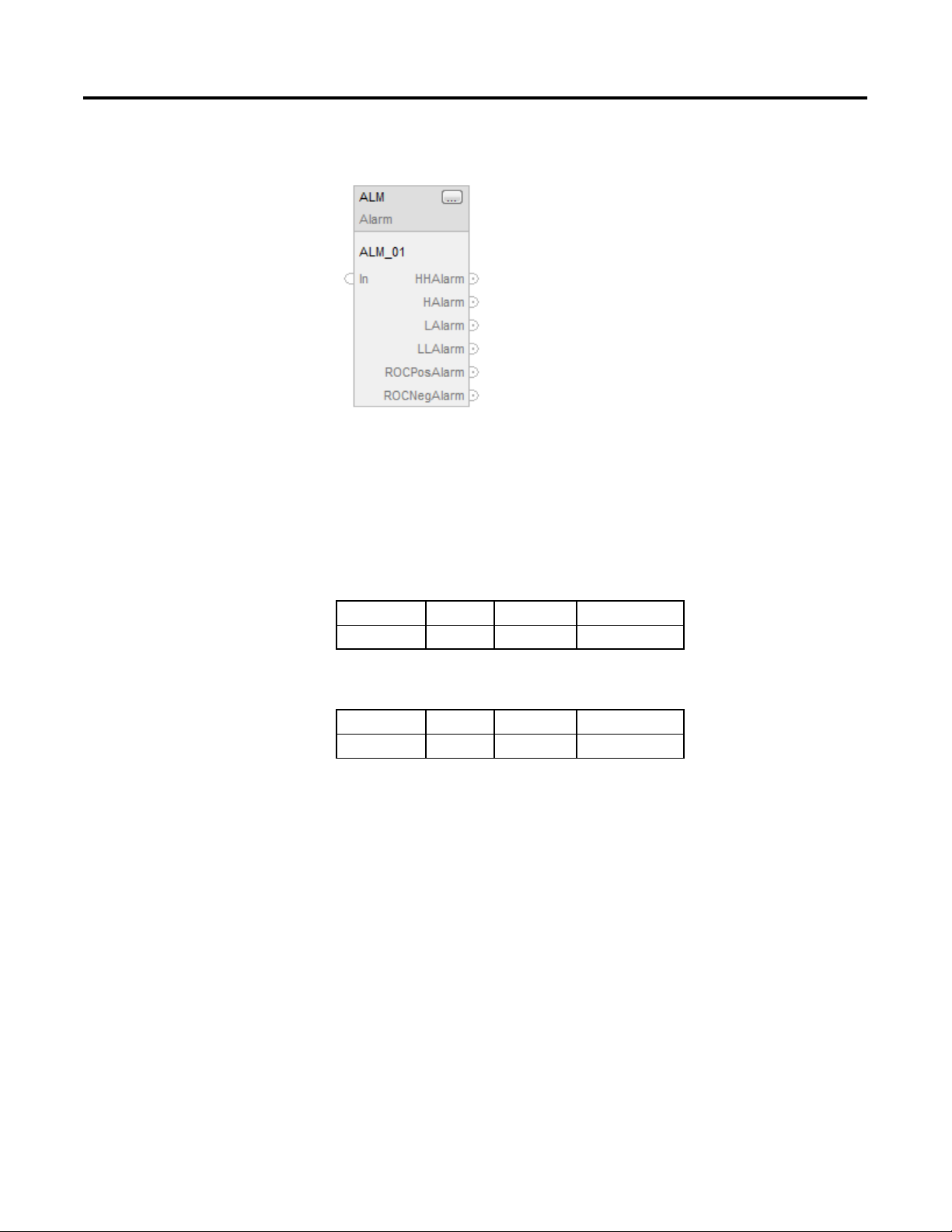
ALM SCL PIDE RMPS POSP SRTP LDLG FGEN
TOT DEDT D2SD D3SD IMC CC MMC
If you want to Use this instruction
Provide alarming for any analog signal. ALM
Control discrete devices, such as solenoid valves, pumps, and motors, that
have only two possible states (e.g., on/off, open/closed, etc.).
D2SD
Control discrete devices, such as high/low/off feeders that have three
possible states (e.g., fast/slow/off, forward/stop/reverse, etc.).
Perform a delay of a single input. You select the amount of deadtime
delay.
Convert an input based on a piece-wise linear function. FGEN
Provide a phase lead-lag compensation for an input signal. LDLG
Regulate an analog output to maintain a process variable at a certain
setpoint, using a PID algorithm.
Raise/lower or open/close a device, such as a motor-operated valve, by
pulsing open or close contacts.
Provide for alternating ramp and soak periods to follow a temperature
profile.
Convert an unscaled input value to a floating point value in engineering
units.
Rockwell Automation Publication 1756-RM006K-EN-P - November 2018 19
D3SD
DEDT
PIDE
POSP
RMPS
SCL
Page 20

Chapter 1
Process Control Instructions
Take the 0-100% output of a PID loop and drive heating and cooling
Alarm (ALM)
digital output contacts with a periodic pulse.
SRTP
Provide a time-scaled accumulation of an analog input value, such as a
volumetric flow.
Control a single process variable by maintaining a single controller output. IMC
Control a single process variable by manipulating as many as three
different control variables.
Control two process variables to their setpoints using up to three control
variables.
TOT
CC
MMC
See also
Filter Instructions on page 319
Logical and Move Instructions on page 401
Drives Instructions on page 263
Select/Limit Instructions on page 349
Statistical Instructions on page 381
This information applies to the CompactLogix 5370, ControlLogix 5570,
Compact GuardLogix 5370, GuardLogix 5570, Compact GuardLogix 5380,
CompactLogix 5380, CompactLogix 5480, ControlLogix 5580, and GuardLogix
5580 controllers.
The ALM instruction provides alarming for any analog signal.
Available Languages
Ladder Diagram
This instruction is not available in ladder diagram logic.
20 Rockwell Automation Publication 1756-RM006K-EN-P - November 2018
Page 21
Process Control Instructions
Chapter 1
Function Block
Structured Text
ALM(ALM_tag)
Operands
Function Block
Operand Type Format Description
ALM tag ALARM structure ALM structure
Structured Text
Operand Type Format Description
ALM tag ALARM structure ALM structure
See Structured Text Syntax for more information on the syntax of expressions
within structured text.
Rockwell Automation Publication 1756-RM006K-EN-P - November 2018 21
Page 22

Chapter 1
Process Control Instructions
ROC negative alarming. If invalid, the instruction assumes a value of
ALARM Structure
Input Parameter Data Type Description
EnableIn BOOL Enable input. If false, the instruction does not execute and outputs
are not updated.
Default is true.
In REAL The analog signal input.
Valid = any float
Default = 0.0
HHLimit REAL The high-high alarm limit for the input.
Valid = any real value
Default = maximum positive value
HLimit REAL The high alarm limit for the input.
Valid = any real value
Default = maximum positive value
LLimit REAL The low alarm limit for the input.
Valid = any real value
Default = maximum negative value
LLLimit REAL The low-low alarm limit for the input.
Valid = any real value
Default = maximum negative value
Deadband REAL The alarm deadband for the high-high to low-low limits
Valid = any real value 0.0
Default = 0.0
ROCPosLimit REAL The rate-of-change alarm limit in units per second for a positive
(increasing) change in the input. Set ROCPosLimit = 0 to disable
ROC positive alarming. If invalid, the instruction assumes a value of
0.0 and sets the appropriate bit in Status.
Valid = any real value 0.0
Default = 0.0
ROCNegLimit REAL The rate-of-change alarm limit in units per second for a negative
(decreasing) change in the input. Set ROCNegLimit = 0 to disable
ROCPeriod REAL Time period in seconds for calculation (sampling interval) of the
22 Rockwell Automation Publication 1756-RM006K-EN-P - November 2018
0.0 and sets the appropriate bit in Status.
Valid = any real value 0.0
Default = 0.0
rate of change value. Each time the sampling interval expires, a
new sample of In is stored, and ROC is re-calculated. Instead of an
enable bit like other conditions in the analog alarm, the rate-ofchange detection is enabled by putting any non-zero value in the
ROCPeriod.
Valid = 0.0 to 32767.0
Default = 0.0.
Page 23
Process Control Instructions
Chapter 1
Output Parameter Data Type Description
EnableOut BOOL Indicates if instruction is enabled. Cleared to false if ROC
overflows.
HHAlarm BOOL The high-high alarm indicator.
Default = false
HAlarm BOOL The high alarm indicator.
Default = false
LAlarm BOOL The low alarm indicator.
Default = false
LLAlarm BOOL The low-low alarm indicator.
Default = false
ROCPosAlarm BOOL The rate-of-change positive alarm indicator.
Default = false
ROCNegAlarm BOOL The rate-of-change negative alarm indicator.
Default = false
ROC REAL The rate-of-change output.
Status DINT Status of the function block.
InstructFault (Status.0) BOOL The instruction detected one of the following execution errors.
This is not a minor or major controller error. Check the remaining
status bits to determine what occurred.
DeadbandInv (Status.1) BOOL Invalid Deadband value.
ROCPosLimitInv (Status.2) BOOL Invalid ROCPosLimit value.
ROCNegLimitInv (Status.3) BOOL Invalid ROCNegLimit value.
ROCPeriodInv (Status.4) BOOL Invalid ROCPeriod value.
Description
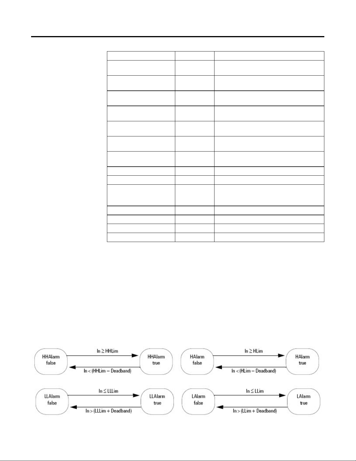
The ALM instruction provides alarm indicators for high-high, high, low, low-low,
rate-of-change positive, and rate-of-change negative. An alarm deadband is
available for the high-high to low-low alarms. A user-defined period for
performing rate-of-change alarming is also available.
High-high to Low-low Alarm
The high-high and low-low alarm algorithms compare the input to the alarm limit
and the alarm limit plus or minus the deadband.
Rockwell Automation Publication 1756-RM006K-EN-P - November 2018 23
Page 24
Chapter 1
Process Control Instructions
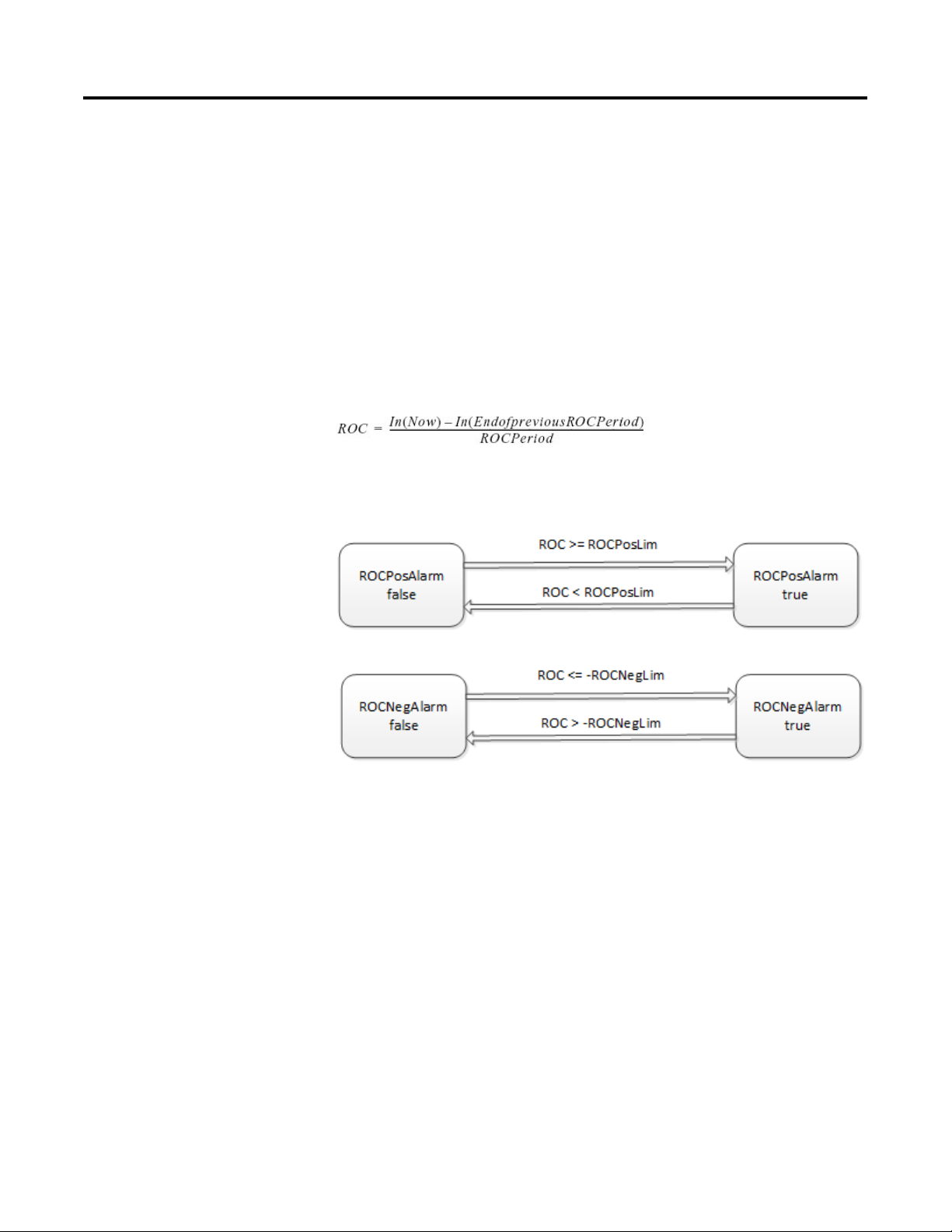
Rate-of-change Alarm
The rate-of-change (ROC) alarm compares the change of the input over the
ROCPeriod to the rate-of-change limits. The ROCPeriod provides a type of
deadband for the rate-of-change alarm. For example, define an ROC alarm limit of
O
F/second with a period of execution of 100 ms. If you use an analog input
2
module with a resolution of 1
O
F, every time the input value changes, an ROC
alarm is generated because the instruction calculates an effective rate of
10°F/second. However, enter an ROCPeriod of 1 sec and the instruction only
O
generates an alarm if the rate truly exceeds the 2
F/second limit.
The ROC alarm calculates the rate-of-change as:
The instruction performs this calculation when the ROCPeriod expires. Once the
instruction calculates the ROC, it determines alarms as:
Monitoring the ALM Instruction
There is an operator faceplate available for the ALM instruction.
Affects Math Status Flags
No
Major/Minor Faults
None specific to this instruction. See Common Attributes for operand-related
faults.
24 Rockwell Automation Publication 1756-RM006K-EN-P - November 2018
Page 25
Process Control Instructions
Chapter 1
Execution
Function Block
Condition/State Action Taken
Prescan Rung-condition-in bits are cleared to false.
Rung-condition-in is false Rung-condition-in bits are cleared to false.
Rung-condition-in is true Rung-condition-in bits are set to true.
The instruction executes.
Postscan Rung-condition-in bits are cleared to false.
Structured Text
Condition/State Action Taken
Prescan See Prescan in the Function Block table.
Normal Execution See Rung-condition-in is true in the Function Block table.
Postscan See Postscan in the Function Block table.
Example
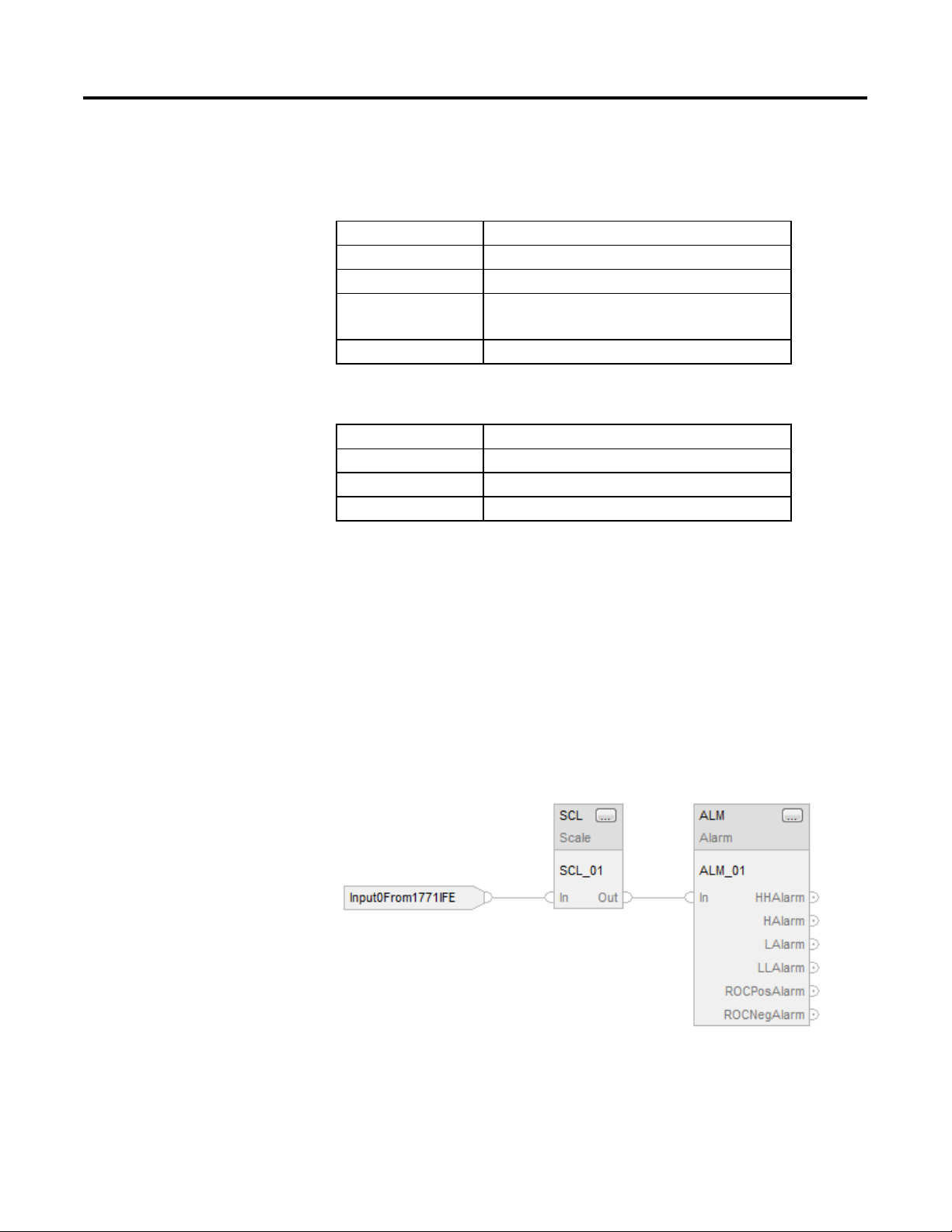
The ALM instruction is typically used either with analog input modules (such as
1771 I/O modules) that do not support on-board alarming, or to generate alarms
on a calculated variable. In this example, an analog input from a 1771-IFE module
is first scaled to engineering units using the SCL instruction. The Out of the SCL
instruction is an input to the ALM instruction to determine whether to set an
alarm. The resulting alarm output parameters could then be used in your program
and/or viewed on an operator interface display.
Function Block
Rockwell Automation Publication 1756-RM006K-EN-P - November 2018 25
Structured Text
SCL_01.IN := Input0From1771IFE;
Page 26

Chapter 1
Process Control Instructions
SCL(SCL_01);
Discrete 3-State Device
ALM_01.IN := SCL_01.Out;
ALM(ALM_01);
See also
(D3SD)
Common Attributes on page 537
Structured Text Syntax on page 508
Function Block Faceplate Controls on page 552
This information applies to the CompactLogix 5370, ControlLogix 5570,
Compact GuardLogix 5370, GuardLogix 5570, Compact GuardLogix 5380,
CompactLogix 5380, CompactLogix 5480, ControlLogix 5580, and GuardLogix
5580 controllers.
The D3SD instruction controls a discrete device having three possible states, such
as fast/slow/off or forward/stop/reverse.
Available Languages
Ladder Diagram
This instruction is not available in ladder diagram logic.
26 Rockwell Automation Publication 1756-RM006K-EN-P - November 2018
Page 27
Process Control Instructions
Chapter 1
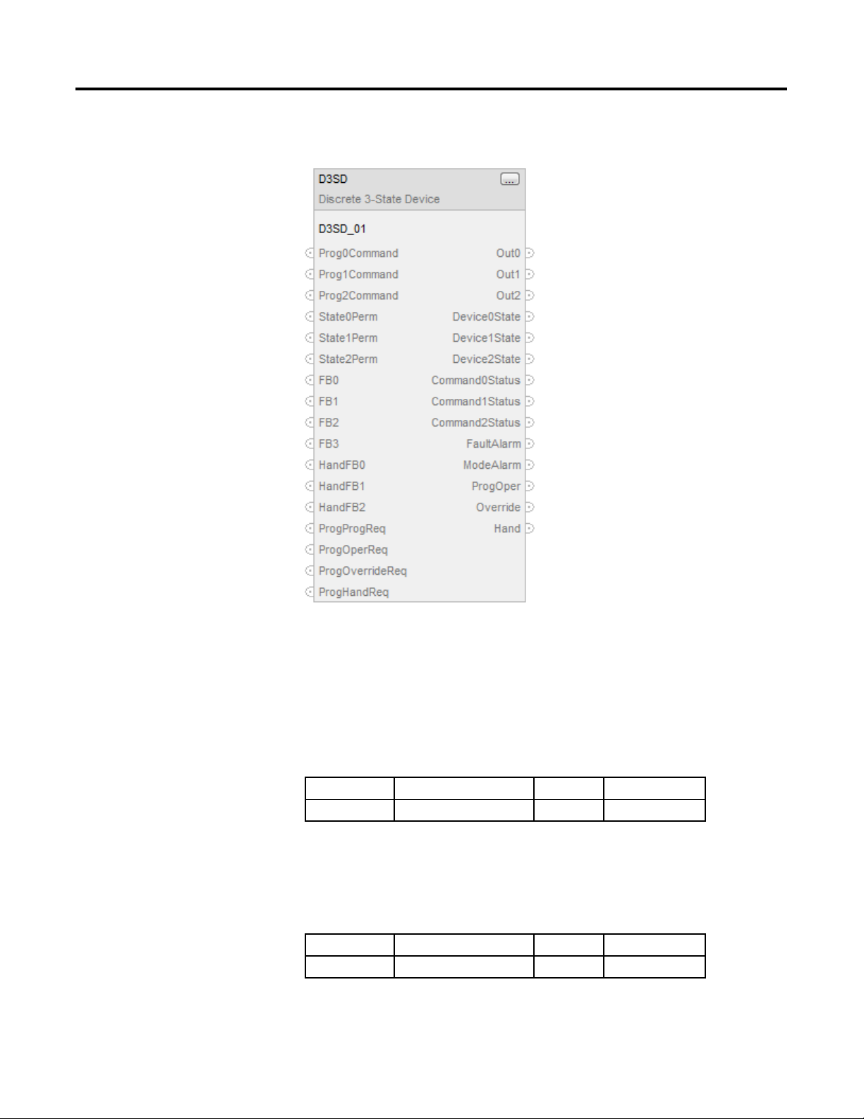
Function Block
Structured Text
D3SD(D3SD_tag)
Operands
Structured Text
Operand Type Format Description
D3SD tag DISCRETE_3STATE structure D3SD structure
See Structured Text Syntax for more information on the syntax of expressions
within structured text.
Function Block
Operand Type Format Description
D3SD tag DISCRETE_3STATE structure D3SD structure
Rockwell Automation Publication 1756-RM006K-EN-P - November 2018 27
Page 28

Chapter 1
Process Control Instructions
DISCRETE_3STATE Structure
Input Parameter Data
Type
EnableIn BOOL Enable input. If false, the instruction does not execute and outputs are not
Prog0Command BOOL Program state 0 command. This input determines the device state when the
Prog1Command BOOL Program state 1 command. This input determines the device state when the
Prog2Command BOOL Program state 2 command. This input determines the device state when the
Oper0Req BOOL Operator state 0 request. Set to true by the operator interface to place the device
Oper1Req BOOL Operator state 1 request. Set true by the operator interface to place the device into
Oper2Req BOOL Operator state 2 request. Set to true by the operator interface to place the device
State0Perm BOOL State 0 permissive. Unless in Hand or Override mode, this input must be true for
State1Perm BOOL State 1 permissive. Unless in Hand or Override mode, this input must be true for
State2Perm BOOL State 2 permissive. Unless in Hand or Override mode, this input must be true for
FB0 BOOL The first feedback input available to the instruction.
FB1 BOOL The second feedback input available to the instruction.
FB2 BOOL The third feedback input available to the instruction.
FB3 BOOL The fourth feedback input available to the instruction.
HandFB0 BOOL Hand feedback state 0. This input from a field hand/off/auto station shows the
Description
updated.
Default is true.
device is in Program control. If true, the device is commanded to the 0 state.
Default is false.
device is in Program control. If true, the device is commanded to the 1 state.
Default is false.
device is in Program control. If true, the device is commanded to the 2 state.
Default is false.
into the 0 state when the device is in Operator control.
Default is false.
the 1 state when the device is in Operator control.
Default is false.
into the 2 state when the device is in Operator control.
Default is false.
the device to enter the 0 state. This input has no effect if the device is already in
the 0 state.
Default is true.
the device to enter the 1 state. This input has no effect if the device is already in
the 1 state.
Default is true.
the device to enter the 2 state. This input has no effect if the device is already in
the 2 state.
Default is true.
Default is false.
Default is false.
Default is false.
Default is false.
requested state of the field device. True indicates the field device is being
requested to enter the 0 state; false indicates the field device is being requested to
enter some other state.
Default is false.
28 Rockwell Automation Publication 1756-RM006K-EN-P - November 2018
Page 29

Process Control Instructions
Chapter 1
Input Parameter Data
Type
HandFB1 BOOL Hand feedback state 1. This input from a field hand/off/auto station shows the
HandFB2 BOOL Hand feedback state 2. This input from a field hand/off/auto station shows the
FaultTime REAL Fault time value. Configure the value in seconds of the time to allow the device to
FaultAlarmLatch BOOL Fault alarm latch input. When true and FaultAlarm is true, latch FaultAlarm. To
FaultAlmUnLatch BOOL Fault alarm unlatch input. Set this input to true when FaultAlarmLatch is set to
OverrideOnInit BOOL Override on initialization request. If this bit is true, then during instruction first
OverrideOnFault BOOL Override on fault request. Set this value to true if the device should go to Override
Out0State0 BOOL Output 0 state 0 input. This value determines the value of Output0 when the
Out0State1 BOOL Output 0 state 1 input. This value determines the value of Output0 when the
Out0State2 BOOL Output 0 state 2 input. This value determines the value of Output0 when the
Out1State0 BOOL Output 1 state 0 input. This value determines the value of Output1 when the
Out1State1 BOOL Output 1 state 1 input. This value determines the value of Output1 when the
Out1State2 BOOL Output 1 state 2 input. This value determines the value of Output1 when the
Description
requested state of the field device. True indicates the field device is being
requested to enter the 1 state; false indicates the field device is being requested to
enter some other state.
Default is false.
requested state of the field device. True indicates the field device is being
requested to enter the 2 state; false indicates the field device is being requested to
enter some other state.
Default is false.
reach a newly commanded state. Set FaultTime = 0 to disable the fault timer. If
this value is invalid, the instruction assumes a value of zero and sets the
appropriate bit in Status.
Valid = any float 0.0
Default = 0.0
unlatch FaultAlarm, set FaultAlmUnlatch to true or clear FaultAlarmLatch to false.
Default is false.
unlatch FaultAlarm. The instruction clears this input to false.
Default is false.
scan, the instruction is placed in Operator control with Override true and Hand
false. If ProgHandReq is true, then Override is cleared to false and Hand is set to
true.
Default is false.
mode and enter the Override State on a fault alarm. After the fault alarm is
removed, the instruction is placed in Operator control.
Default is false.
device is in the 0 state.
Default is false.
device is in the 1 state.
Default is false.
device is in the 2 state.
Default is false.
device is in the 0 state.
Default is false.
device is in the 1 state.
Default is false.
device is in the 2 state.
Default is false.
Rockwell Automation Publication 1756-RM006K-EN-P - November 2018 29
Page 30

Chapter 1
Process Control Instructions
Input Parameter Data
Type
Out2State0 BOOL Output 2 state 0 input. This value determines the value of Output2 when the
Out2State1 BOOL Output 2 state 1 input. This value determines the value of Output2 when the
Out2State2 BOOL Output 2 state 2 input. This value determines the value of Output2 when the
OverrideState DINT Override state input. Set this input to indicate the state of the device when in
FB0State0 BOOL Feedback 0 state 0 input. This value determines the expected value of FB0 when
FB0State1 BOOL Feedback 0 state 1 input. This value determines the expected value of FB0 when
FB0State2 BOOL Feedback 0 state 2 input. This value determines the expected value of FB0 when
FB1State0 BOOL Feedback 1 state 0 input. This value determines the expected value of FB1 when
FB1State1 BOOL Feedback 1 state 1 input. This value determines the expected value of FB1 when
FB1State2 BOOL Feedback 1 state 2 input. This value determines the expected value of FB1 when
FB2State0 BOOL Feedback 2 state 0 input. This value determines the expected value of FB2 when
FB2State1 BOOL Feedback 2 state 1 input. This value determines the expected value of FB2 when
FB2State2 BOOL Feedback 2 state 2 input. This value determines the expected value of FB2 when
FB3State0 BOOL Feedback 3 state 0 input. This value determines the expected value of FB3 when
FB3State1 BOOL Feedback 3 state 1 input. This value determines the expected value of FB3 when
Description
device is in the 0 state.
Default is false.
device is in the 1 state.
Default is false.
device is in the 2 state.
Default is false.
Override mode.
2 = Device should go to the 2 state
1 = Device should go to the 1 state
0 = Device should go to the 0 state
An invalid value sets the appropriate bit in Status.
Valid = 0 to 2
Default = 0
the device is in the 0 state.
Default is false.
the device is in the 1 state.
Default is false.
the device is in the 2 state.
Default is false.
the device is in the 0 state.
Default is false.
the device is in the 1 state.
Default is false.
the device is in the 2 state.
Default is false.
the device is in the 0 state.
Default is false.
the device is in the 1 state.
Default is false.
the device is in the 2 state.
Default is false.
the device is in the 0 state.
Default is false.
the device is in the 1 state.
Default is false.
30 Rockwell Automation Publication 1756-RM006K-EN-P - November 2018
Page 31

Process Control Instructions
Chapter 1
Input Parameter Data
Type
FB3State2 BOOL Feedback 3 state 2 input. This value determines the expected value of FB3 when
ProgProgReq BOOL Program program request. Set to true by the user program to request Program
ProgOperReq BOOL Program operator request. Set to true by the user program to request operator
ProgOverrideReq BOOL Program override request. Set to true by the user program to request the device to
ProgHandReq BOOL Program hand request. Set to true by the user program to request the device to
OperProgReq BOOL Operator program request. Set to true by the operator interface to request
OperOperReq BOOL Operator operator request. Set to true by the operator interface to request
ProgValueReset BOOL Reset program control values. When true, all the program request inputs are
Description
the device is in the 2 state.
Default is false.
control. Ignored if ProgOperReq is true. Holding this true and ProgOperReq false
locks the instruction in Program control.
Default is false.
control. Holding this true locks the instruction in Operator control.
Default is false.
enter Override mode. Ignored if ProgHandReq is true.
Default is false.
enter Hand mode.
Default is false.
Program control. The instruction clears this input to false.
Default is false.
Operator control. The instruction clears this input to false.
Default is false.
cleared to false at each execution of the instruction.
Default is false.
Output Parameter Data Type Description
EnableOut BOOL Indicates if instruction is enabled.
Out0 BOOL The first output of the instruction.
Out1 BOOL The second output of the instruction.
Out2 BOOL The third output of the instruction.
Device0State BOOL Device state 0 output. True when the device
is commanded to the 0 state and the
feedback indicates the device really is in the
0 state.
Device1State BOOL Device state 1 output. True when the device
is commanded to the 1 state and the
feedback indicates the device really is in the
1 state.
Device2State BOOL Device state 2 output. True when the device
is commanded to the 2 state and the
feedback indicates the device really is in the
2 state.
Command0Status BOOL Device state 0 command status. True when
the device is being commanded to the 0
state; false when the device is being
commanded to some other state.
Rockwell Automation Publication 1756-RM006K-EN-P - November 2018 31
Page 32

Chapter 1
Process Control Instructions
Command1Status BOOL Device state 1 command status. True when
the device is being commanded to the 1
state; false when the device is being
commanded to some other state.
Command2Status BOOL Device state 2 command status. True when
the device is being commanded to the 2
state; false when the device is being
commanded to some other state.
FaultAlarm BOOL Fault alarm output. True if the device has
been commanded to a new state, and the
FaultTime has expired without the feedback
indicating that the new state has actually
been reached. Also set to true if, after
reaching a commanded state, the feedbacks
suddenly indicate that the device is no
longer in the commanded state.
ModeAlarm BOOL Mode alarm output. True if the device is in
operator control and a ProgxCommand input
requests a state which is different from the
state currently commanded by the operator.
This alarm is intended as a reminder that a
device was left in Operator control.
ProgOper BOOL Program/operator control indicator. True
when in Program control. False when in
Operator control.
Override BOOL Override mode. True when the device is in
the Override mode.
Hand BOOL Hand mode. True when the device is in the
Hand mode.
Status DINT Status of the function block.
InstructFault (Status.0) BOOL The instruction detected one of the following
execution errors. This is not a minor or major
controller error. Check the remaining status
bits to determine what occurred.
FaultTimeInv (Status.1) BOOL Invalid FaultTime value. The instruction sets
FaultTime = 0.
OverrideStateInv (Status.2) BOOL The Override value is out of range. It
prevents the instruction from entering the
Override state.
ProgCommandInv (Status.3) BOOL Multiple program state command bits are set
at the same time. Refer to Commanded State
in Program Control section.
OperReqInv (Status.4) BOOL Multiple operator state request bits are set at
the same time. Refer to Commanded State in
Program Control section.
32 Rockwell Automation Publication 1756-RM006K-EN-P - November 2018
HandCommandInv (Status.5) BOOL Multiple hand feedback state request bits are
set at the same time.
Page 33

Process Control Instructions
Chapter 1
Description
The D3SD instruction controls a discrete device having three possible states, such
as fast/slow/off or forward/stop/reverse. Typical discrete devices of this nature
include feeder systems, and reversible motors.
Affects Math Status Flags
No
Major/Minor Faults
None specific to this instruction. See Common Attributes for operand-related
faults.
Execution
Function Block
Condition/State Action Taken
Prescan EnableIn and EnableOut bits are cleared to false.
Tag.EnableIn is false EnableIn and EnableOut bits are cleared to false.
Tag.EnableIn is true EnableIn and EnableOut bits are set to true.
The instruction executes
Instruction first run Set ProgOper to Operator Mode.
Set Command0Status to True.
Set Command1Status to False.
Set Command2Status to False.
Instruction first scan The fault timer is cleared.
ModeAlarm is cleared to false.
All the operator request inputs are cleared to false.
If ProgValueReset is true, all the program request inputs are
cleared to false.
When OverrideOnInit is true, ProgOper is cleared to false(Operator
control).
If ProgHandReq is false and OverrideOnInit is true, Hand is cleared
to false and Override is set to true (Override mode).
If ProgHandReq is true, Hand is set to true and Override is cleared
to false(Hand mode).
Postscan EnableIn and EnableOut bits are cleared to false.
Rockwell Automation Publication 1756-RM006K-EN-P - November 2018 33
Page 34

Chapter 1
Process Control Instructions
Structured Text
In Structured Text, EnableIn is always true during normal scan. Therefore, if the
instruction is in the control path activated by the logic it will execute.
Condition/State Action Taken
Prescan See Prescan in the Function Block table.
Normal Execution See Tag.EnableIn is true in the Function Block table.
Postscan See Postscan in the Function Block table.
Examples
The D3SD instruction is typically used to control 3-state devices such as
high/low/off feed systems. In this example, the D3SD instruction controls a feed
system consisting of a pair of solenoid valves adding vegetable oil to a batch tank.
One of the valves is on a large diameter feed pipe into the batch tank, and the
other valve is plumbed in parallel on a small diameter feed pipe. When oil is first
added, the D3SD instruction is commanded to the fast feed state (state 2) where
both valves are opened. When the oil added approaches the target amount, the
D3SD instruction is commanded to the slow feed state (state 1) where the "large
valve" is closed and the "small valve" is kept open. When the target is reached, the
D3SD instruction is commanded to go to the off state (state 0) and both valves are
closed. As long as the D3SD instruction is in Program control, the valves open
according to the CloseOilFeed, SlowOilFeed, and FastOilFeed inputs. The
operator can also take Operator control of the feed system if necessary. The
solenoid valves in this example have limit switches which indicate when the valves
are fully closed or opened. These switches are wired into the FB0, FB1, FB2, and
FB3 feedback inputs. This allows the D3SD instruction to generate a FaultAlarm
if the solenoid valves do not reach their commanded states within the configured
FaultTime.
34 Rockwell Automation Publication 1756-RM006K-EN-P - November 2018
Page 35

Process Control Instructions
Chapter 1
Function Block
Structured Text
OilFeedController.Prog0Command := ClosedOilFeed;
OilFeedController.Prog1Command := SlowOilFeed;
OilFeedController.Prog1Command := FastOilFeed;
OilFeedController.FB0 := SmallOilValveClosed;
OilFeedController.FB1 := SmallOilValveOpened;
OilFeedController.FB2 := LargeOilValveClosed;
OilFeedController.FB3 := LargeOilValveOpened;
D3SD(OilFeedController);
SmallOilValve := OilFeedController.Out0;
LargeOilValve := OilFeedController.Out1;
Rockwell Automation Publication 1756-RM006K-EN-P - November 2018 35
Page 36

Chapter 1
Process Control Instructions
Switch Between Program Control and Operator Control
The following diagram shows how the D3SD instruction changes between
Program control and Operator control.
(1) The instruction remains in Operator control mode when ProgOperReq is
true.
Commanded State in Program Control
The following table shows how the D3SD instruction operates when in Program
control.
Prog0
Command
false false true either either true Command0Status is cleared to false
false true false either true either Command0Status is cleared to false
true false false true either either Command0Status is set to true
Prog1
Command
Prog2
Command
State0
Perm
State1
Perm
State2
Perm
Description
Command1Status is cleared to false
Command2Status is set to true
Command1Status is set to true
Command2Status is cleared to false
Command1Status is cleared to false
Command2Status is cleared to false
If more than one program command input is true:
• The instruction sets the appropriate bit in Status
36 Rockwell Automation Publication 1756-RM006K-EN-P - November 2018
• If Override and Hand are cleared to false, the instruction holds the previous
state
Page 37

Process Control Instructions
Chapter 1
Commanded State in Operator Control
The following table shows how the D3SD instruction operates when in Operator
control.
State1
Oper0Req Oper1Req Oper2Req State0 Perm
false false true either either true Command0Status is cleared to false
false true false either true either Command0Status is cleared to false
true false false true either either Command0Status is set to true
Perm State2 Perm Description
Command1Status is cleared to false
Command2Status is set to true
Command1Status is set to true
Command2Status is cleared to false
Command1Status is cleared to false
Command2Status is cleared to false
If more than one operator command input is true:
• The instruction sets the appropriate bit in Status
• If Override and Hand are cleared to false, the instruction holds the previous
state
After every instruction execution, the instruction:
• Clears all the operator request inputs
• If ProgValueReset is true, clears all the program request inputs to false
Hand Mode or Override Mode
The following table describes how the D3SD instruction determines whether to
operate in Hand or Override mode.
ProgHandReq ProgOverrideReq FaultAlarm and OverrideOnFault Description
true either either Hand mode
Hand is set to true
Override is cleared to false
false true either Override mode
Hand is cleared to false
Override is set to true
false either true Override mode
Hand is cleared to false
Override is set to true
When Override is set, it takes precedence over Program and Operator control.
The following table describes how the Override mode affects the commanded
state.
Rockwell Automation Publication 1756-RM006K-EN-P - November 2018 37
Page 38

Chapter 1
Process Control Instructions
Override Override State Description
true 2 Command0Status is cleared to false
Command1Status is cleared to false
Command2Status is set to true
true 1 Command0Status is cleared to false
Command1Status is set to true
Command2Status is cleared to false
true 0 Command0Status is set to true
Command1Status is cleared to false
Command2Status is cleared to false
If OverrideState is invalid, the instruction sets the appropriate bit in Status and
does not enter the override state.
When Hand is true, it takes precedence over Program and Operator control. The
following table describes how the Hand mode affects the commanded state.
Hand HandFB0 HandFB1 HandFB2 Description
true false false true Command0Status is cleared to false
Command1Status is cleared to false
Command2Status is set to true
true false true false Command0Status is cleared to false
Command1Status is set to true
Command2Status is cleared to false
true true false false Command0Status is set to true
Command1Status is cleared to false
Command2Status is cleared to false
If more than one HandFB input is true, the instruction sets the appropriate bit in
Status and, if Hand is true, the instruction holds the previous state.
38 Rockwell Automation Publication 1756-RM006K-EN-P - November 2018
Page 39

Process Control Instructions
Chapter 1
Output State
The D3SD output state is based on the state of the command status.
CommandStatus Output State
Command0Status is true Out0 = Out0State0
Out1 = Out1State0
Out2 = Out2State0
Command0Status is true and
FB0 = FB0State0 and
FB1 = FB1State0 and
FB2 = FB2State0 and
FB3 = FB3State0
Command1Status is true Out0 = Out0State1
Command1Status is true and
FB0 = FB0State1 and
FB1 = FB1State1 and
FB2 = FB2State1 and
FB3 = FB3State1
Command2Status is true Out0 = Out0State2
Command2Status is true and
FB0 = FB0State2 and
FB1 = FB1State2 and
FB2 = FB2State2 and
FB3 = FB3State2
Stop and clear the fault timer.
Device0State is set to true
Out1 = Out1State1
Out2 = Out2State1
Stop and clear the fault timer.
Device1State is set to true
Out1 = Out1State2
Out2 = Out2State2
Stop and clear the fault timer.
Device2State is set to true
Fault Alarm Conditions
The D3SD instruction checks for these fault alarm conditions.
Fault alarm condition resulting from Rules
Device state was commanded to change,
but the feedback did not indicate that the
desired state was actually reached within
the FaultTime
The device unexpectedly left a state
(according to the feedback) without
being commanded to
Rockwell Automation Publication 1756-RM006K-EN-P - November 2018 39
Start the fault timer when Command0Statusn Command0Status
Command1Statusn Command1Status
Command2Status
n-1
or Command2Statusn
n-1
n-1
Set FaultAlarm when the fault timer done and FaultTime > 0.0
Set FaultAlarm to true when the fault timer is not timing and one of the
following conditions is satisfied:
Command0Status is true and Device0State is false
Command1Status is true and Device1State is false
Command2Status is true and Device2State is false
or
Page 40

Chapter 1
Process Control Instructions
If there is no fault present, FaultAlarm is cleared to false if one of the following
conditions is met:
• Command0Status is true and Device0State is true
• Command1Status is true and Device1State is true
• Command2Status is true and Device2State is true
• FaultTime 0
FaultAlarm cannot be cleared to false when FaultAlarmLatch is true, unless
FaultAlmUnlatch is true and no fault is present.
Mode Alarm Conditions
The mode alarm reminds an operator that a device has been left in Operator
control. The mode alarm only turns on when, in Operator control mode, the
program tries to change the state of the device from the operator’s commanded
state. The alarm does not turn on if an operator places a device in Operator
control mode and changes the state. The D3SD instruction checks for mode alarm
conditions, using these rules.
ModeAlarm is When
true
false Prog2Command = Command2Status and
Prog2Command Prog2Command
Prog2Command Command2Status or
Prog1Command Prog1Command
Prog1Command Command1Status or
Prog0Command Prog1Command
Prog0Command Command0Status
Prog1Command = Command1Status and
Prog0Command = Command0Status or
The device is in Override, Hand, or Program control mode
See also
Common Attributes on page 537
Structured Text Syntax on page 508
n-1
n-1
n-1
and
and
and
40 Rockwell Automation Publication 1756-RM006K-EN-P - November 2018
Page 41

Process Control Instructions
Chapter 1
Discrete 2-State Device
(D2SD)
This information applies to the CompactLogix 5370, ControlLogix 5570,
Compact GuardLogix 5370, GuardLogix 5570, Compact GuardLogix 5380,
CompactLogix 5380, CompactLogix 5480, ControlLogix 5580, and GuardLogix
5580 controllers.
The D2SD instruction controls a discrete device which has only two possible
states (such as on/off or open/closed).
Available Languages
Ladder Diagram
This instruction is not available in ladder diagram logic.
Function Block
Rockwell Automation Publication 1756-RM006K-EN-P - November 2018 41
Structured Text
D2SD(D2SD_tag)
Operands
There are data conversion rules for mixed data types within an instruction. See
Data Conversion.
Page 42

Chapter 1
Process Control Instructions
Structured Text
Operand Type Format Description
D2SD tag DISCRETE_2STATE Structure D2SD structure
See Structured Text Syntax for more information on the syntax of expressions
within structured text.
Function Block
Operand Type Format Description
D2SD tag DISCRETE_2STATE Structure D2SD structure
DISCRETE_2STATE Structure
Input Parameter Data Type Description
EnableIn BOOL Enable input. If false, the instruction does not execute and
outputs are not updated.
Default is true.
ProgCommand BOOL Used to determine CommandStatus when the device is in
Program control. When true, the device is commanded to
the 1 state; when false, the device is commanded to the 0
state.
Default is false.
Oper0Req BOOL Operator state 0 request. Set by the operator interface to
place the device in the 0 state when the device is in
Operator control.
Default is false.
Oper1Req BOOL Operator state 1 request. Set by the operator interface to
place the device in the 1 state when the device is in
Operator control.
Default is false.
State0Perm BOOL State 0 permissive. Unless in Hand or Override mode, this
input must be set for the device to enter the 0 state. This
input has no effect for a device already in the 0 state.
Default is true.
State1Perm BOOL State 1 permissive. Unless in the Hand or Override mode,
this input must be set for the device to enter the 1 state.
This input has no effect for a device already in the 1 state.
Default is true.
FB0 BOOL The first feedback input available to the D2SD instruction.
Default is false.
FB1 BOOL The second feedback input available to the D2SD
instruction.
Default is false.
HandFB BOOL Hand feedback input. This input is from a field
hand/off/auto station and it shows the requested state of
the field device. When true, the field device is being
requested to enter the 1 state; when false, the field device
is being requested to enter the 0 state.
Default is false.
42 Rockwell Automation Publication 1756-RM006K-EN-P - November 2018
Page 43

Process Control Instructions
Chapter 1
FaultTime REAL Fault time value. Configure the value in seconds of the
time to allow the device to reach a newly commanded
state. Set FaultTime = 0 to disable the fault timer. If this
value is invalid, the instruction assumes a value of zero
and sets the appropriate bit in Status.
Valid = any float 0.0
Default = 0.0
FaultAlarmLatch BOOL Fault alarm latch input. When true and FaultAlarm is true,
latch FaultAlarm. To unlatch FaultAlarm set
FaultAlmUnlatch to true or clear FaultAlarmLatch to false.
Default is false.
FaultAlmUnLatch BOOL Fault alarm unlatch input. Set FaultAlmUnLatch when
FaultAlarmLatch is set to unlatch FaultAlarm. The
instruction clears this input to false.
Default is false.
OverrideOnInit BOOL Override on initialization request. If this bit is true, then
during instruction first scan, the 2-state device is placed in
Operator control, Override is set to true, and Hand is
cleared to false. If ProgHandReq is true, then Override is
cleared to false and Hand is set to true.
Default is false.
OverrideOnFault BOOL Override on fault request. Set OverrideOnFault to true if
the device should go to Override mode and enter the
OverrideState on a fault alarm. After the fault alarm is
removed, the 2-state device is placed in Operator control.
Default is false.
OutReverse BOOL Reverse default out state. The default state of Out is
cleared to false when commanded to state 0, and set to
true when commanded to state 1. When OutReverse is
true, Out is set to true when commanded to state 0, and
cleared to false when commanded to state 1.
Default is false.
OverrideState BOOL Override state input. Configure this value to specify the
state of the device when the device is in Override mode.
True indicates the device should go to the 1 state; false
indicates the device should go to the 0 state.
Default is false.
FB0State0 BOOL Feedback 0 state 0 input. Configure the state of the FB0
when the device is in the 0 state.
Default is false.
FB0State1 BOOL Feedback 0 state 1 input. Configure the state of the FB0
when the device is in the 1 state.
Default is false.
FB1State0 BOOL Feedback 1 state 0 input. Configure the state of the FB1
when the device is in the 0 state.
Default is false.
FB1State1 BOOL Feedback 1 state 1 input. Configure the state of the FB1
when the device is in the 1 state.
Default is false.
ProgProgReq BOOL Program program request. Set to true by the user
program to request Program control. Ignored if
ProgOperReq is true. Holding this true and ProgOperReq
false locks the instruction into Program control.
Default is false.
Rockwell Automation Publication 1756-RM006K-EN-P - November 2018 43
Page 44

Chapter 1
Process Control Instructions
ProgOperReq BOOL Program operator request. Set to true by the user
program to request Operator control. Holding this true
locks the instruction into Operator control.
Default is false.
ProgOverrideReq BOOL Program override request. Set to true by the user program
to request the device to enter Override mode. Ignored if
ProgHandReq is true.
Default is false.
ProgHandReq BOOL Program hand request. Set to true by the user program to
request the device to enter Hand mode.
Default is false.
OperProgReq BOOL Operator program request. Set to true by the operator
interface to request Program control. The instruction
clears this input to false.
Default is false.
OperOperReq BOOL Operator operator request. Set to true by the operator
interface to request Operator control. The instruction
clears this input to false.
Default is false.
ProgValueReset BOOL Reset program control values. When true, all the program
request inputs are cleared to false at each execution of the
instruction.
Default is false.
Output Parameter Data Type Description
EnableOut BOOL Indicates if instruction is enabled.
Out BOOL The output of the 2-state instruction.
Device0State BOOL Device 0 state output. Set to true when the device is
commanded to the 0 state and the feedbacks indicate the
device really is in the 0 state.
Device1State BOOL Device 1 state output. Set to true when the device is
commanded to the 1 state and the feedbacks indicate the
device really is in the 1 state.
CommandStatus BOOL Command status output. Set to true when the device is
being commanded to the 1 state and cleared when the
device is being commanded to the 0 state.
FaultAlarm BOOL Fault alarm output. Set to true if the device was
commanded to a new state and the FaultTime has expired
without the feedbacks indicating that the new state has
actually been reached. Also set to true if, after reaching a
commanded state, the feedbacks suddenly indicate that
the device is no longer in the commanded state.
ModeAlarm BOOL Mode alarm output. Set to true if the device is in Operator
control and a program command changes to a state which
is different from the state currently commanded by the
operator. This alarm is intended as a reminder that a
device was left in Operator control.
ProgOper BOOL Program/Operator control indicator. True when in
Program control. False when in Operator control.
Override BOOL Override mode. True when the device is in the Override
mode.
44 Rockwell Automation Publication 1756-RM006K-EN-P - November 2018
Page 45

Process Control Instructions
Chapter 1
Hand BOOL Hand mode. True when the device is in the Hand mode.
Status DINT Status of the function block.
InstructFault (Status.0) BOOL The instruction detected one of the following execution
errors. This is not a minor or major controller error. Check
the remaining status bits to determine what occurred.
FaultTimeInv (Status.1) BOOL Invalid FaultTime value. The instruction sets FaultTime =
0.
OperReqInv (Status.2) BOOL Both operator state request bits are true.
Description
The D2SD instruction controls a discrete device which has only two possible
states (such as on/off or open/closed). Typical discrete devices of this nature
include motors, pumps, and solenoid valves.
Monitoring the D2SD Instruction
There is an operator faceplate available for the D2SD instruction.
Affects Math Status Flags
No
Major/Minor Faults
None specific to this instruction. See Common Attributes for operand-related
faults.
Execution
Function Block
Condition/State Action Taken
Prescan EnableIn and EnableOut bits are cleared to false.
Tag.EnableIn is false EnableIn and EnableOut bits are cleared to false.
Tag.EnableIn is true EnableIn and EnableOut bits are set to true.
The instruction executes.
Instruction first run Set ProgOper to Operator Mode. Set CommandStatus to False.
Instruction first scan Set EnableOut to true.
ModeAlarm and operator request inputs are cleared to false,
If ProgValueReset is true, all the program request inputs are cleared to
false.
When OverrideOnInit is true, ProgOper is cleared to false (Operator
control).
If ProgHandReq is cleared and OverrideOnInit is set, clear Hand and set
Override (Override mode).
If ProgHandReq is set, set Hand and clear Override (Hand mode).
Postscan EnableIn and EnableOut bits are cleared to false.
Rockwell Automation Publication 1756-RM006K-EN-P - November 2018 45
Page 46

Chapter 1
Process Control Instructions
Structured Text
In Structured Text, EnableIn is always true during normal scan. Therefore, if the
instruction is in the control path activated by the logic it will execute.
Condition/State Action Taken
Prescan See Prescan in the Function Block table.
Normal Execution See Tag.EnableIn is true in the Function Block table.
Postscan See Postscan in the Function Block table.
Examples
SD instruction is typically used to control on-off or open-close devices such as
pumps or solenoid valves. In this example, the D2SD instruction controls a
solenoid valve adding corn syrup to a batch tank. As long as the D2SD instruction
is in Program control, the valve opens when the AddSyrup input is set. The
operator can also take Operator control of the valve to open or close it if necessary
The solenoid valve in this example has limit switches that indicate when the valve
is fully closed or opened. These switches are wired into the FB0 and FB1 feedback
inputs. This allows the D2SD instruction to generate a FaultAlarm if the solenoid
valve does not reach the commanded state within the configured FaultTime.
Function Block
46 Rockwell Automation Publication 1756-RM006K-EN-P - November 2018
Page 47

Process Control Instructions
Chapter 1
Structured Text
SyrupController.ProgCommand := AddSyrup;
SyrupController.FB0 := SyrupValveClosedLimitSwitch;
SyrupController.FB1 := SyrupValveOpenedLimitSwitch;
D2SD(SyrupController);
SyrupValve := SyrupController.Out;
Switch Between Program Control and Operator Control
The following diagram shows how the D2SD instruction changes between
Program control and Operator control.
Rockwell Automation Publication 1756-RM006K-EN-P - November 2018 47
(1) The instruction remains in Operator control mode when ProgOperReq is
true.
Page 48

Chapter 1
Process Control Instructions
Commanded State in Program Control
The following diagram shows how the D2SD instruction operates when in
Program control.
Commanded State in Operator Control
The following diagram shows how the D2SD instruction operates when in
Operator control.
If both Oper0Req and Oper1Req are true:
• The instruction sets the appropriate bit in Status to true
• If Override and Hand are false, the instruction holds the previous state.
After every instruction execution, the instruction:
• Clears all the operator request inputs to false
• If ProgValueReset is true, clears all the program request inputs to false
48 Rockwell Automation Publication 1756-RM006K-EN-P - November 2018
Page 49

Process Control Instructions
Chapter 1
Hand Mode or Override Mode
The following table describes how the D2SD instruction determines whether to
operate in Hand or Override mode.
FaultAlarm and
ProgHandReq ProgOverrideReq
true either either Hand mode
false true either Override mode
false either true Override mode
OverrideOnFault Description
Hand is set to true
Override is cleared to false
Hand is cleared to false
Override is set to true
Hand is cleared to false
Override is set to true
When the instruction is in Override mode, CommandStatus = OverrideState.
When the instruction is in Hand mode, CommandStatus = HandFB.
Output State
The D2SD output state is based on the state of the command status.
CommandStatus Output State
false If OutReverse is false, Out is cleared to false
If OutReverse is true, Out is set to true
true If OutReverse is false, Out is set to rue
If OutReverse is true, Out is cleared to false
false and
FB0 = FB0State0 and
FB1 = FB1State0
true and
FB0 = FB0State1 and
FB1 = FB1State1
The fault timer is stopped and cleared to 0
Device0State is set to true
The fault timer is stopped and cleared to 0
Device1State is set to true
Rockwell Automation Publication 1756-RM006K-EN-P - November 2018 49
Page 50

Chapter 1
Process Control Instructions
Fault Alarm Conditions
The D2SD instruction checks for these fault alarm conditions.
Fault alarm condition
resulting from Rules
Device state was commanded to change, but the
feedback did not indicate that the desired state
was actually reached within the FaultTime
The device unexpectedly left a state (according
to the feedback) without being commanded to
Start the fault timer when CommandStatus
Set FaultAlarm when faulttimer is done and FaultTime > 0.0
Set FaultAlarm to true when the fault timer is not timing and one of the
following conditions is satisfied:
CommandStatus is false and Device0State is false
CommandStatus is true and Device1State is false
CommandStatus
n
FaultAlarm is cleared to false if one of the following conditions is met:
• CommandStatus is false and Device0State is true
• CommandStatus is true and Device1State is true
• FaultTime 0
FaultAlarm cannot be cleared to false when FaultAlarmLatch is true, unless
FaultAlmUnlatch is true and no fault is present.
n-1
Mode Alarm Conditions
The mode alarm reminds an operator that a device has been left in Operator
control. The mode alarm only turns on when, in Operator control mode, the
program tries to change the state of the device from the operator’s commanded
state. The alarm does not turn on if an operator places a device in Operator
control mode and changes the state. The D2SD instruction checks for mode alarm
conditions, using these rules.
ModeAlarm When
True ProgCommand n ProgCommandn-1 and
ProgCommand
False ProgCommand = CommandStatus or
the device is in Override, Hand, or Program control mode
CommandStatus
n
See also
Common Attributes on page 537
Structured Text Syntax on page 508
Data Conversions on page 541
50 Rockwell Automation Publication 1756-RM006K-EN-P - November 2018
Page 51

Process Control Instructions
Chapter 1
Deadtime (DEDT)
This information applies to the CompactLogix 5370, ControlLogix 5570,
Compact GuardLogix 5370, GuardLogix 5570, Compact GuardLogix 5380,
CompactLogix 5380, CompactLogix 5480, ControlLogix 5580, and GuardLogix
5580 controllers.
The DEDT instruction performs a delay of a single input. You select the amount
of deadtime delay.
Available Languages
Ladder Diagram
This instruction is not available in ladder diagram logic.
Function Block
Structured Text
DEDT(DEDT_tag,storage);
Operands
Structured Text
Operand Type Format Description
DEDT tag DEADTIME structure DEDT structure
storage REAL array deadtime buffer
See Structured Text Syntax for more information on the syntax of expressions
within structured text.
Function Block
Operand Type Format Description
DEDT tag DEADTIME structure DEDT structure
storage REAL array deadtime buffer
Rockwell Automation Publication 1756-RM006K-EN-P - November 2018 51
Page 52

Chapter 1
Process Control Instructions
DEADTIME Structure
Input Parameter Data Type Description
EnableIn BOOL Enable input. If false, the instruction does
not execute and outputs are not updated.
Default is true.
In REAL The analog signal input to the instruction.
Valid = any float
Default = 0.0
InFault BOOL Bad health indicator for the input. If the
input value is read from an analog input,
then InFault is controlled by fault status on
the analog input. If true, InFault indicates
the input signal has an error, the instruction
sets the appropriate bit in Status, the control
algorithm is not executed, and Out is held.
Default is false.
false = good health
Deadtime REAL Deadtime input to the instruction. Enter the
deadtime in seconds. If this value is invalid,
the instruction assumes a value of zero and
sets the appropriate bit in Status.
Valid = 0.0 to (StorageArray size * DeltaT)
Default = 0.0
Gain REAL Gain input to the instruction. The value of In
is multiplied by this value. This allows
simulation of a process gain.
Valid = any float
Default = 1.0
Bias REAL Bias input to the instruction. The value of In
multiplied by the Gain is added to this value.
This allows simulation of an ambient
condition.
Valid = any float
Default = 0.0
TimingMode DINT Selects timing execution mode.
0 = Period mode
1 = oversample mode
2 = real time sampling mode
Valid = 0 to 2
Default = 0
For more information about timing modes,
see Function Block Attributes.
OversampleDT REAL Execution time for oversample mode.
Valid = 0 to 4194.303 seconds
Default = 0
RTSTime DINT Module update period for real time sampling
mode
Valid = 1 to 32,767ms
Default = 1
RTSTimeStamp DINT Module time stamp value for real time
sampling mode.
Valid = 0 to 32,767ms
Default = 0
52 Rockwell Automation Publication 1756-RM006K-EN-P - November 2018
Page 53

Process Control Instructions
Chapter 1
Output Parameter Data Type Description
EnableOut BOOL Indicates if instruction is enabled. Cleared to
false if Out overflows.
Out REAL The calculated output of the deadtime
algorithm.
DeltaT REAL Elapsed time between updates. This is the
elapsed time in seconds used by the control
algorithm to calculate the process output.
Status DINT Status of the function block.
InstructFault
(Status.0)
InFaulted (Status.1) BOOL In health is bad.
DeadtimeInv
(Status.2)
TimingMode
(Status.27)
RTSMissed (Status.28) BOOL Only used in real time sampling mode. Set
RTSTimeInv
(Status.29)
RTSTimeStampInv
(Status.30)
DeltaTInv (Status.31) BOOL Invalid DeltaT value.
BOOL The instruction detected one of the following
execution errors. This is not a minor or major
controller error. Check the remaining status
bits to determine what occurred.
BOOL Invalid Deadtime value.
BOOL Invalid TimingMode value.
For more information about timing modes, see
Function Block Attributes.
when
ABS(DeltaT - RTSTime) > 1 millisecond.
BOOL Invalid RTSTime value.
BOOL Invalid RTSTimeStamp value.
Description
The DEDT instruction uses a data buffer to store delayed data, thereby allowing
any length deadtime desired. The DEDT instruction is designed to execute in a
task where the scan rate remains constant.
To use the DEDT instruction, create a storage array to store the deadtime buffer
to hold the samples of (In x Gain) + Bias. The storage array should be large enough
to hold the largest desired deadtime, using this formula:
StorageArray Size Needed = Maximum Deadtime (secs) / DeltaT (secs)
Servicing the Deadtime Buffer
During runtime, the instruction checks for a valid Deadtime. Deadtime must be
between 0.0 and (StorageArray Size x DeltaT).
If the Deadtime is invalid, the instruction sets an appropriate Status bit and sets
Out = (In x Gain) + Bias.
Rockwell Automation Publication 1756-RM006K-EN-P - November 2018 53
Page 54

Chapter 1
Process Control Instructions
The deadtime buffer functions as a first-in, first-out buffer. Every time the
deadtime algorithm executes, the oldest value in the deadtime buffer is moved into
Out. The remaining values in the buffer shift downward and the value ((In x
Gain) + Bias) is moved to the beginning of the deadtime buffer. A new value that
is placed in the deadtime buffer appears in the Out after Deadtime seconds.
The number of array elements required to perform the programmed delay is
calculated by dividing Deadtime by DeltaT. If Deadtime is not evenly divisible by
DeltaT, then the number of array elements and the programmed delay are
rounded to the nearest increment of DeltaT. For example, to find the number of
array elements required to perform the programmed delay given Deadtime = 4.25s
and DeltaT = 0.50s:
4.25s / 0.50s = 8.5
rounds up to 9 array elements required
The actual delay applied to the input in this example is:
number of array elements x DeltaT = programmed delay or
9 x 0.5s = 4.5s
Runtime changes to either Deadtime or DeltaT change the point in which values
are moved out of the buffer. The number of elements required to perform the
programmed delay can either increase or decrease. Prior to servicing the deadtime
buffer, the following updates occur:
If the number of required elements needs to increase, the new buffer elements are
populated with the oldest value in the current deadtime buffer.
If the number of required elements needs to decrease, the oldest elements of the
current deadtime buffer are discarded.
Instruction Behavior on InFault Transition
When InFault is true (bad), the instruction suspends execution, holds the last
output, and sets the appropriate bit in Status.
When InFault transitions from true to false, the instruction sets all values in the
deadtime buffer equal to In x Gain + Bias.
Affects Math Status Flags
No
54 Rockwell Automation Publication 1756-RM006K-EN-P - November 2018
Major/Minor Faults
None specific to this instruction. See Common Attributes for operand-related
faults.
Page 55

Process Control Instructions
Chapter 1
Execution
Function Block
Condition/State Action Taken
Prescan EnableIn and EnableOut bits are cleared to false.
Tag.EnableIn is false EnableIn and EnableOut bits are cleared to false.
Tag.EnableIn is true EnableIn and EnableOut bits are set to true.
The instruction executes.
Instruction first run N/A
Instruction first scan N/A
The instruction does not execute, but does validate input
parameters.
Postscan EnableIn and EnableOut bits are cleared to false.
Structured Text
Condition/State Action Taken
Prescan See Prescan in the Function Block table.
Normal Execution See Tag.EnableIn is true in the Function Block table.
Postscan See Postscan in the Function Block table.
Example
In this example, the DEDT instruction simulates a deadtime delay in a simulated
process. The output of the PIDE instruction is passed through a deadtime delay
and a first-order lag to simulate the process. The array DEDT_01array is a REAL
array with 100 elements to support a deadtime of up to 100 samples. For example,
if this routine executes every 100 msec, the array would support a deadtime of up
to 10 seconds.
Rockwell Automation Publication 1756-RM006K-EN-P - November 2018 55
Page 56

Chapter 1
Process Control Instructions
Function Block
Function Generator (FGEN)
See also
Com
mon Attributes on page 537
Structured Text Syntax on page 508
This information applies to the CompactLogix 5370, ControlLogix 5570,
Compact GuardLogix 5370, GuardLogix 5570, Compact GuardLogix 5380,
CompactLogix 5380, CompactLogix 5480, ControlLogix 5580, and GuardLogix
5580 controllers.
The FGEN instruction converts an input based on a piece-wise linear function.
Available Languages
Ladder Diagram
This instruction is not available in ladder diagram.
56 Rockwell Automation Publication 1756-RM006K-EN-P - November 2018
Page 57

Process Control Instructions
Chapter 1
Function Block
Structured Text
FGEN(FGEN_tag,X1,Y1,X2,Y2);
Operands
Function Block
Operand Type Format Description
FGEN tag FUNCTION_
GENERATOR
X1 REAL array X-axis array, table one. Combine with the Y-axis array, table one to
Y1 REAL array Y-axis array, table one. Combine with the X-axis array, table one to
X2 REAL array (optional)
Y2 REAL array (optional)
structure FGEN structure
define the points of the first piece-wise linear curve.
Valid = any float
define the points of the first piece-wise linear curve.
Valid = any float
X-axis array, table two. Combine with the Y-axis array, table two to
define the points of the second piece-wise linear curve.
Valid = any float
Y-axis array, table two. Combine with the X-axis array, table two to
define the points of the second piece-wise linear curve.
Valid = any float
Rockwell Automation Publication 1756-RM006K-EN-P - November 2018 57
Page 58

Chapter 1
Process Control Instructions
Structured Text
Operand Type Format Description
FGEN tag FUNCTION_
GENERATOR
X1 REAL array X-axis array, table one. Combine with the Y-axis array, table one to
Y1 REAL array Y-axis array, table one. Combine with the X-axis array, table one to
X2 REAL array (optional)
Y2 REAL array (optional)
structure FGEN structure
define the points of the first piece-wise linear curve.
Valid = any float
define the points of the first piece-wise linear curve.
Valid = any float
X-axis array, table two. Combine with the Y-axis array, table two to
define the points of the second piece-wise linear curve.
Valid = any float
Y-axis array, table two. Combine with the X-axis array, table two to
define the points of the second piece-wise linear curve.
Valid = any float
See Structured Text Syntax for more information on the syntax of expressions
within structured text.
FUNCTION_GENERATOR Structure
Input Parameter Data Type Description
EnableIn BOOL Enable input. If false, the instruction does not execute and
outputs are not updated.
Default is true.
In REAL The analog signal input to the instruction.
Valid = any float
Default = 0.0
XY1Size DINT Number of points in the piece-wise linear curve to use from
table one. If the value is less than one and Select is cleared,
the instruction sets the appropriate bit in Status and the
output is not changed.
Valid = 1 to (smallest of X1 and Y1 array sizes)
Default = 1
XY2Size DINT Number of points in the piece-wise linear curve to use from
table two. If the value is less than one and Select is set, the
instruction sets the appropriate bit in Status and the output
is not changed.
Valid = 0 to (smallest of X2 and Y2 array sizes)
Default = 0
Select BOOL This input determines which table to use. When cleared,
the instruction uses table one; when set, the instruction
uses table two.
Default is cleared.
58 Rockwell Automation Publication 1756-RM006K-EN-P - November 2018
Page 59

Process Control Instructions
Chapter 1
Output Parameter Data Type Description
EnableOut BOOL Indicates if instruction is enabled. Cleared to false on
overflow
Out REAL Output of the instruction.
Status DINT Status of the function block.
InstructFault (Status.0) BOOL Instruction generated a fault.
XY1SizeInv (Status.1) BOOL Size of table 1 is invalid or not compatible with the array
size.
XY2SizeInv (Status.2) BOOL Size of table 2 is invalid or not compatible with the array
size.
XisOutofOrder (Status.3) BOOL The X parameters are not sorted.
Description
The following illustration shows how the FGEN instruction converts a twelvesegment curve.
Rockwell Automation Publication 1756-RM006K-EN-P - November 2018 59
The X-axis parameters must follow the relationship:
X[1] < X[2] < X[3] < ... < X[XY<n>Size],
where XY<n>Size > 1 and is a number of points in the piece-wise linear curve and
where n is 1 or 2 for the table selected. You must create sorted X-axis elements in
the X arrays.
The Select input determines which table to use for the instruction. When the
instruction is executing on one table, you can modify the values in the other table.
Change the state of Select to execute with the other table.
Page 60

Chapter 1
Process Control Instructions
Before calculating Out, the X axis parameters are scanned. If they are not sorted in
ascending order, the appropriate bit in Status is set and Out remains unchanged.
Also, if XY1Size or XY2Size is invalid, the instruction sets the appropriate bit in
Status and leaves Out unchanged.
The instruction uses this algorithm to calculate Out based on In:
• When In X[1], set Out = Y[1]
• When In > X[XY<n>Size], set Out = Y[XY<n>Size]
• When X[n] < In X[n+1], calculate Out = ((Y[n+1]-Yn)/ (X[n+1]-
Xn))*(In-Xn)+Yn
Affects Math Status Flags
No
Major/Minor Fault
None specific to this instruction. See Common Attributes for operand-related
faults.
Execution
Function Block
Condition Function Block Action
Prescan EnableIn and EnableOut bits are cleared to false.
Tag.EnableIn is false EnableIn and EnableOut bits are cleared to false.
Tag.EnableIn is true EnableIn and EnableOut bits are set to true. The instruction executes.
Instruction first run N/A
Instruction first scan N/A
Postscan EnableIn and EnableOut bits are set to true. The instruction executes.
Structured Text
Condition/State Action Taken
Prescan See Prescan in the Function Block table.
Normal Execution See Tag.EnableIn is true in the Function Block table.
Postscan See Postscan in the Function Block table.
60 Rockwell Automation Publication 1756-RM006K-EN-P - November 2018
Page 61

Process Control Instructions
Chapter 1
Examples
Example 1
In this example, the FGEN instruction characterizes a flow signal which is then
totalized using a TOT instruction. The FGEN_01X1 and FGEN_01Y1 arrays are
REAL arrays of 10 elements each to support up to a 9 segment curve. You can use
arrays of any size to support a curve of any desired number of segments.
Example
2
This example passes optional parameters to FGEN instruction.
See also
Com
mon Attributes on page 537
Structured Text Syntax on page 508
Rockwell Automation Publication 1756-RM006K-EN-P - November 2018 61
Page 62

Chapter 1
Process Control Instructions
Lead-Lag (LDLG)
This information applies to the CompactLogix 5370, ControlLogix 5570,
Compact GuardLogix 5370, GuardLogix 5570, Compact GuardLogix 5380,
CompactLogix 5380, CompactLogix 5480, ControlLogix 5580, and GuardLogix
5580 controllers.
The LDLG instruction provides a phase lead-lag compensation for an input signal.
This instruction is typically used for feedforward PID control or for process
simulations.
Available Languages
Ladder Diagram
This instruction is not available in ladder diagram.
Function Block
Structured Text
LDLG(LDLG_tag);
Operands
Function Block
Operand Type Format Description
LDLG tag LEAD_LAG Structure LDLG structure
Structured Text
Operand Type Format Description
LDLG tag LEAD_LAG Structure LDLG structure
See Structured Text Syntax for more information on the syntax of expressions
within structured text.
62 Rockwell Automation Publication 1756-RM006K-EN-P - November 2018
Page 63

Process Control Instructions
Chapter 1
LEAD_LAG Structure
Input Parameter Data Type Description
EnableIn BOOL Enable input. If cleared, the instruction does not execute and
outputs are not updated.
Default is set.
In REAL The analog signal input to the instruction.
Valid = any float
Default = 0.0
Initialize BOOL Request to initialize filter control algorithm. When Initialize is
set, Out = (In x Gain) + Bias.
Default = cleared
Lead REAL The lead time in seconds. Set Lead = 0.0 to disable the lead
control algorithm. If Lead < 0.0, the instruction sets the
appropriate bit in Status and limits Lead to 0.0. If Lead >
maximum positive float, the instruction sets the appropriate
bit in Status.
Valid = any float 0.0
Default = 0.0
Lag REAL The lag time in seconds. The minimum lag time is DeltaT/2. If
Lag < DeltaT/2, the instruction sets the appropriate bit in
Status and limits Lag to DeltaT/2. If Lag > maximum positive
float, the instruction sets the appropriate bit in Status.
Valid = any float DeltaT/2
Default = 0.0
Gain REAL The process gain multiplier. This value allows the simulation of
a process gain. The In signal is multiplied by this value. I = (In
x Gain) + Bias
Valid = any float
Default = 1.0
Bias REAL The process offset level. This value allows the simulation of an
ambient condition. This value is summed with the results of
the multiplication of In times Gain. I = (In x Gain) + Bias
Valid = any float
Default = 0.0
TimingMode DINT Selects timing execution mode.
0 = Periodic rate
1 = Oversample mode
2 = Real-time sampling mode
Valid = 0 to 2
Default = 0
For more information about timing modes, see Function Block
Attributes.
OversampleDT REAL Execution time for oversample mode.
Valid = 0 to 4194.303 seconds
Default = 0
RTSTime DINT Module update period for real time sampling mode
Valid = 1 to 32,767ms
Default = 1
RTSTimeStamp DINT Module time stamp value for real time sampling mode.
Valid = 0 to 32,767ms
Default = 0
Rockwell Automation Publication 1756-RM006K-EN-P - November 2018 63
Page 64

Chapter 1
Process Control Instructions
Output Parameter Data Type Description
EnableOut BOOL Enable output.
Out REAL The calculated output of the algorithm. Math status flags are
used for this output.
DeltaT REAL Elapsed time between updates. This is the elapsed time in
seconds used by the control algorithm to calculate the process
output.
Status DINT Status of the function block.
InstructFault (Status.0) BOOL The instruction detected one of the following execution errors.
This is not a minor or major controller error. Check the
remaining status bits to determine what occurred.
LeadInv (Status.1) BOOL Lead < minimum value or Lead > maximum value.
LagInv (Status.2) BOOL Lag < minimum value or Lag > maximum value.
TimingModeInv (Status.27) BOOL Invalid TimingMode value.
For more information about timing modes, see Function Block
Attributes.
RTSMissed (Status.28) BOOL Only used in real time sampling mode. Set when
ABS | DeltaT - RTSTime | > 1 (.001 second).
RTSTimeInv (Status.29) BOOL Invalid RTSTime value.
RTSTimeStampInv
(Status.30)
DeltaTInv (Status.31) BOOL Invalid DeltaT value.
BOOL Invalid RTSTimeStamp value.
Description
The LDLG instruction supports one lead and lag in series. The instruction also
allows configurable gain and bias factors. The LDLG instruction is designed to
execute in a task where the scan rate remains constant.
The LDLG instruction uses this equation:
with these parameter limits:
Parameter Limitations
Lead LowLimit = 0.0
HighLimit = maximum positive float
Lag LowLimit = DeltaT/2 (DeltaT is in seconds)
HighLimit = maximum positive float
Whenever the value computed for the output is invalid, NAN, or INF, the
instruction sets Out = the invalid value and sets the Math overflow status flag.
64 Rockwell Automation Publication 1756-RM006K-EN-P - November 2018
Page 65

Process Control Instructions
Chapter 1
When the value computed for the output becomes valid, the instruction initializes
the internal parameters and sets Out = (In x Gain) + Bias.
Math Status Flags
No
Major/Minor Faults
None specific to this instruction. See Common Attributes for operand-related
faults.
Execution
Function Block
Condition Function Block Action
Prescan EnableIn and EnableOut bits are cleared to false.
Tag.EnableIn is false EnableIn and EnableOut bits are cleared to false.
Tag.EnableIn is true EnableIn and EnableOut bits are set to true.
The instruction executes.
Instruction first run N/A
Instruction first scan Execute "Out = (In * Gain) + Bias".
Recalculate Lead/Lag coefficients.
Postscan EnableIn and EnableOut bits are cleared to false.
Structured Text
Condition/State Action Taken
Prescan See Prescan in the Function Block table.
Normal Execution See Tag.EnableIn is true in the Function Block table.
Postscan See Postscan in the Function Block table.
Example
The LDLG instruction in this example adds a first-order lag to a simulated
process. Optionally, you could enter a Gain on the LDLG instruction to simulate
a process gain, and you could enter a Bias to simulate an ambient condition.
Rockwell Automation Publication 1756-RM006K-EN-P - November 2018 65
Page 66

Chapter 1
Process Control Instructions
Function Block
Structu
red Text
DEDT_01.In := SimulatedLoop.CVEU;
DEDT(DEDT_01,DEDT_01_array);
LDLG_01.In := DEDT_01.Out;
LDLG(LDLG_01);
SimulatedLoop.PV := LDLG_01.Out;
PIDE(SimulatedLoop);
See also
Function Block Attributes on page 491
Common Attributes on page 537
Structured Text Syntax on page 508
66 Rockwell Automation Publication 1756-RM006K-EN-P - November 2018
Page 67

Process Control Instructions
Chapter 1
Enhanced PID (PIDE)
This information applies to the CompactLogix 5370, ControlLogix 5570,
Compact GuardLogix 5370, GuardLogix 5570, Compact GuardLogix 5380,
CompactLogix 5380, CompactLogix 5480, ControlLogix 5580, and GuardLogix
5580 controllers.
The PIDE instruction provides enhanced capabilities over the standard PID
instruction. The instruction uses the velocity form of the PID algorithm. The gain
terms are applied to the change in the value of error or PV, not the value of error
or PV.
Available Languages
Ladder Diagram
This instruction is not available in ladder diagram.
Function Block
Rockwell Automation Publication 1756-RM006K-EN-P - November 2018 67
Page 68

Chapter 1
Process Control Instructions
Maximum scaled value for PV. The value of PV and SP which corresponds to 100 percent
Structured Text
PIDE(PIDE_tag);
Operands
Function Block
Operand Type Format Description
PIDE tag PID_ENHANCED structure PIDE structure
autotune tag PIDE_AUTOTUNE structure (optional)
autotune structure
Structured Text
Operand Type Format Description
PIDE tag PID_ENHANCED structure PIDE structure
See Structured Text Syntax for more information on the syntax of expressions
within structured text.
PIDE Structure
Input Parameter Data Type Description
EnableIn BOOL Enable input. If false, the instruction does not execute and outputs are not updated.
Default is true.
PV REAL Scaled process variable input. This value is typically read from an analog input module.
Valid = any float
Default = 0.0
PVFault BOOL PV bad health indicator. If PV is read from an analog input, then PVFault is normally
controlled by the analog input fault status. When PVFault is true, it indicates the input
signal has an error.
Default is false = "good health"
PVEUMax REAL
span of the Process Variable.
Valid = PVEUMin < PVEUMax maximum positive float
Default = 100.0
PVEUMin REAL Minimum scaled value for PV. The value of PV and SP which corresponds to 0 percent
span of the Process Variable.
Valid = maximum negative float PVEUMin < PVEUMax
Default = 0.0
SPProg REAL SP program value, scaled in PV units. SP is set to this value when in Program control
and not Cascade/Ratio mode. If the value of SPProg < SPLLimit or > SPHLimit, the
instruction sets the appropriate bit in Status and limits the value used for SP.
Valid = SPLLimit to SPHLimit
Default = 0.0
68 Rockwell Automation Publication 1756-RM006K-EN-P - November 2018
Page 69

Process Control Instructions
Chapter 1
Ratio high limit value. Limits the value of Ratio obtained from RatioProg or RatioOper. If
SPOper REAL SP operator value, scaled in PV units. SP is set to this value when in Operator control
and not Cascade/Ratio mode. If the value of SPOper < SPLLimit or > SPHLimit, the
instruction sets the appropriate bit in Status and limits the value used for SP.
Valid = SPLLimit to SPHLimit
Default = 0.0
SPCascade REAL SP Cascade value, scaled in PV units. If CascadeRatio is true and UseRatio is false, then
SP = SPCascade. This is typically the CVEU of a primary loop. If CascadeRatio and
UseRatio are true, then SP = (SPCascade x Ratio). If the value of SPCascade < SPLLimit
or > SPHLimit, set the appropriate bit in Status and limit the value used for SP.
Valid = SPLLimit to SPHLimit
Default = 0.0
SPHLimit REAL SP high limit value, scaled in PV units. If SPHLimit > PVEUMax, the instruction sets the
appropriate bit in Status.
Valid = SPLLimit to PVEUMax
Default = 100.0
SPLLimit REAL SP low limit value, scaled in PV units. If SPLLimit < PVEUMin, the instruction sets the
appropriate bit in Status. If SPHLimit < SPLLimit, the instruction sets the appropriate
bit in Status and limits SP using the value of SPLLimit.
Valid = PVEUMin to SPHLimit
Default = 0.0
UseRatio BOOL Allow ratio control permissive. Set to true to enable ratio control when in Cascade/Ratio
mode.
Default is false.
RatioProg REAL Ratio program multiplier. Ratio and RatioOper are set equal to this value when in
Program control. If RatioProg < RatioLLimit or > RatioHLimit, the instruction sets the
appropriate bit in Status and limits the value used for Ratio.
Valid = RatioLLimit to RatioHLimit
Default = 1.0
RatioOper REAL Ratio operator multiplier. Ratio is set equal to this value when in Operator control. If
RatioOper < RatioLLimit or > RatioHLimit, the instruction sets the appropriate bit in
Status and limits the value used for Ratio.
Valid = RatioLLimit to RatioHLimit
Default = 1.0
RatioHLimit REAL
RatioHLimit < RatioLLimit, the instruction sets the appropriate bit in Status and limits
Ratio using the value of RatioLLimit.
Valid = RatioLLimit to maximum positive float
Default = 1.0
RatioLLimit REAL Ratio low limit value. Limits the value of Ratio obtained from RatioProg or RatioOper. If
RatioLLimit < 0, the instruction sets the appropriate bit in Status and limits the value to
zero. If RatioHLimit < RatioLLimit, the instruction sets the appropriate bit in Status and
limits Ratio using the value of RatioLLimit.
Valid = 0.0 to RatioHLimit
Default = 1.0
CVFault BOOL Control variable bad health indicator. If CVEU controls an analog output, then CVFault
normally comes from the analog output’s fault status. When true, CVFault indicates an
error on the output module and the instruction sets the appropriate bit in Status.
Default is false = "good health"
CVInitReq BOOL CV initialization request. This signal is normally controlled by the "In Hold" status on
the analog output module controlled by CVEU or from the InitPrimary output of a
secondary PID loop.
Default is false.
Rockwell Automation Publication 1756-RM006K-EN-P - November 2018 69
Page 70

Chapter 1
Process Control Instructions
CVInitValue REAL CVEU initialization value, scaled in CVEU units. When CVInitializing is true, CVEU =
CVInitValue and CV equals the corresponding percentage value. CVInitValue comes
from the feedback of the analog output controlled by CVEU or from the setpoint of a
secondary loop. Instruction initialization is disabled when CVFaulted or CVEUSpanInv is
true.
Valid = any float
Default = 0.0
CVProg REAL CV program manual value. CV equals this value when in Program Manual mode. If
CVProg < 0 or > 100, or < CVLLimit or > CVHLimit when CVManLimiting is true, the
instruction sets the appropriate bit in Status and limits the CV value.
Valid = 0.0 to 100.0
Default = 0.0
CVOper REAL CV operator manual value. CV equals this value when in Operator Manual mode. If not
Operator Manual mode, the instruction sets CVOper = CV at the end of each instruction
execution. If CVOper < 0 or > 100, or < CVLLimit or > CVHLimit when CVManLimiting
is true, the instruction sets the appropriate bit in Status and limits the CV value.
Valid = 0.0 to 100.0
Default = 0.0
CVOverride REAL CV override value. CV equals this value when in override mode. This value should
correspond to a safe state output of the PID loop. If CVOverride < 0 or >100, the
instruction sets the appropriate bit in Status and limits the CV value.
Valid = 0.0 to 100.0
Default = 0.0
CVPrevious REAL CV
value. If CVSetPrevious is set, CV
n-1
equals this value. CV
n-1
is the value of CV from
n-1
the previous execution. CVPrevious is ignored when in manual, override or hand mode
or when CVInitializing is set. If CVPrevious < 0 or > 100, or < CVLLimit or > CVHLimit
when in Auto or cascade/ratio mode, the instruction sets the appropriate bit in Status
and limits the CVn-1 value.
Valid = 0.0 to 100.0
Default = 0.0
CVSetPrevious BOOL Request to use CVPrevious. If true, CVn-1 = CVPrevious
Default is false.
CVManLimiting BOOL Limit CV in manual mode request. If Manual mode and CVManLimiting is true, CV is
limited by the CVHLimit and CVLLimit values.
Default is false.
CVEUMax REAL Maximum value for CVEU. The value of CVEU which corresponds to 100 percent CV. If
CVEUMax = CVEUMin, the instruction sets the appropriate bit in Status.
Valid = any float
Default = 100.0
CVEUMin REAL Minimum value of CVEU. The value of CVEU which corresponds to 0 percent CV. If
CVEUMax = CVEUMin, the instruction sets the appropriate bit in Status.
Valid = any float
Default = 0.0
CVHLimit REAL CV high limit value. This is used to set the CVHAlarm output. It is also used for limiting
CV when in Auto or Cascade/Ratio mode, or Manual mode if CVManLimiting is true. If
CVHLimit > 100 or < CVLLimit, the instruction sets the appropriate bit in Status. If
CVHLimit < CVLLimit, the instruction limits CV using the value of CVLLimit.
Valid = CVLLimit < CVHLimit 100.0
Default = 100.0
CVLLimit REAL CV low limit value. This is used to set the CVLAlarm output. It is also used for limiting CV
when in Auto or Cascade/Ratio mode, or Manual mode if CVManLimiting is true. If
CVLLimit < 0 or CVHLimit < CVLLimit, the instruction sets the appropriate bit in Status.
If CVHLimit < CVLLimit, the instruction limits CV using the value of CVLLimit.
Valid = 0.0 CVLLimit < CVHLimit
Default = 0.0
70 Rockwell Automation Publication 1756-RM006K-EN-P - November 2018
Page 71

Process Control Instructions
Chapter 1
When true, HandFBFault indicates an error on the input module and the instruction sets
CVROCLimit REAL CV rate of change limit, in percent per second. Rate of change limiting is only used
when in Auto or Cascade/Ratio modes or Manual mode if CVManLimiting is true. Enter
0 to disable CV ROC limiting. If CVROCLimit < 0, the instruction sets the appropriate bit
in Status and disables CV ROC limiting.
Valid = 0.0 to maximum positive float
Default = 0.0
FF REAL Feed forward value. The value of feed forward is summed with CV after the zero-
crossing deadband limiting has been applied to CV. Therefore changes in FF are always
reflected in the final output value of CV. If FF < -100 or > 100, the instruction sets the
appropriate bit in Status and limits the value used for FF.
Valid = -100.0 to 100.0
Default = 0.0
FFPrevious REAL FF
value. If FF SetPrevous is set, the instruction sets FF
n-1
= FFPrevious. FF
n-1
n-1
is the
valu eof FF from the previous execution. If FFPrevious < -100 or > 100, the instruction
sets the appropriate bit in Status and limits value used for FF
n-1
Valid = -100.0 to 100.0
Default - 0.0
FFSetPrevious BOOL Request to use FFPrevious. If true, FFn-1 = FFPrevious.
Default is false.
HandFB REAL CV Hand feedback value. CV equals this value when in Hand mode and HandFBFault is
false (good health). This value typically comes from the output of a field mounted
hand/ auto station and is used to generate a bumpless transfer out of hand mode. If
HandFB < 0 or > 100, the instruction sets the appropriate bit in Status and limits the
value used for CV.
Valid = 0.0 to 100.0
Default = 0.0
HandFBFault BOOL HandFB value bad health indicator. If the HandFB value is read from an analog input,
then HandFBFault is typically controlled by the status of the analog input channel.
the appropriate bit in Status.
Default is false = "good health"
WindupHIn BOOL Windup high request. When true, the CV cannot integrate in a positive direction. The
signal is typically obtained from the WindupHOut output from a secondary loop.
Default is false.
WindupLIn BOOL Windup low request. When true, the CV cannot integrate in a negative direction. This
signal is typically obtained from the WindupLOut output from a secondary loop.
Default is false.
ControlAction BOOL Control action request. Set to true to calculate error as E = PV - SP; clear to false to
calculate error as E = SP - PV.
Default is false.
DependIndepend BOOL Dependent/independent control request. When true, use the dependent form of the
PID equation; when false, use the independent form of the equations.
Default is false.
PGain REAL Proportional gain. When the independent form of the PID algorithm is selected, enter
the unitless proportional gain into this value. When the dependent PID algorithm is
selected, enter the unitless controller gain into this value. Enter 0 to disable the
proportional control. If PGain < 0, the instruction sets the appropriate bit in Status and
uses a value of PGain = 0.
Valid = 0.0 to maximum positive float
Default = 0.0
Rockwell Automation Publication 1756-RM006K-EN-P - November 2018 71
Page 72

Chapter 1
Process Control Instructions
IGain REAL Integral gain. When the independent form of the PID algorithm is selected, enter the
integral gain in units of 1/minutes into this value. When the dependent PID algorithm
is selected, enter the integral time constant in units of minutes/repeat into this value.
Enter 0 to disable the integral control. If IGain < 0, the instruction sets the appropriate
bit in Status and uses a value of IGain = 0.
Valid = 0.0 to maximum positive float
Default = 0.0
DGain REAL Derivative gain. When the independent form of the PID algorithm is selected, enter the
derivative gain in units of minutes into this value. When the dependent PID algorithm
is used, enter the derivative time constant in units of minutes into this value. Enter 0 to
disable the derivative control. If DGain < 0, the instruction sets the appropriate bit in
Status and uses a value of DGain = 0.
Valid = 0.0 to maximum positive float
Default = 0.0
PVEProportional BOOL Proportional PV control request. When true, calculate the proportional term
(DeltaPTerm) using the change in process variable (PVPercent). When false, use the
change in error (EPercent).
Default is false.
PVEDerivative BOOL Derivative PV control request. When true, calculate the derivative term (DeltaDTerm)
using the change in process variable (PVPercent). When false, use the change in error
(EPercent).
Default is true.
DSmoothing BOOL Derivative Smoothing request. When true, changes in the derivative term are
smoothed. Derivative smoothing causes less output "jitters" as a result of a noisy PV
signal but also limits the effectiveness of high derivative gains.
Default is false.
PVTracking BOOL SP track PV request. Set to true to cause SP to track PV when in manual mode. Ignored
when in Cascade/Ratio or Auto mode.
Default is false.
ZCDeadband REAL Zero crossing deadband range, scaled in PV units. Defines the zero crossing deadband
range. Enter 0 to disable the zero crossing deadband checking. If ZCDeadband < 0, the
instruction sets the appropriate bit in Status and disables zero crossing deadband
checking.
Valid = 0.0 to maximum positive float
Default = 0.0
ZCOff BOOL Zero crossing disable request. Set to true to disable zero crossing for the deadband
calculation.
Default is false.
PVHHLimit REAL PV high-high alarm limit value, scaled in PV units.
Valid = any float
Default = maximum positive float
PVHLimit REAL PV high alarm limit value, scaled in PV units.
Valid = any float
Default = maximum positive float
PVLLimit REAL PV low alarm limit value, scaled in PV units.
Valid = any float
Default = maximum negative float
PVLLLimit REAL PV low-low alarm limit value, scaled in PV units.
Valid = any float
Default = maximum negative float
PVDeadband REAL PV alarm limit deadband value, scaled in PV units. Deadband is the delta value
between the turn-on and turn-off value for each of the PV alarm limits. If PVDeadband
< 0.0, the instruction sets the appropriate bit in Status and limits PVDeadband to zero.
Valid = 0.0 to maximum positive float
Default = 0.0
72 Rockwell Automation Publication 1756-RM006K-EN-P - November 2018
Page 73

Process Control Instructions
Chapter 1
PVROCPosLimit REAL PV positive rate of change alarm limit. The limit value for a positive (increasing) change
in PV, scaled in PV units per seconds. Enter 0.0 to disable positive PVROC alarm
checking. If PVROCPosLimit < 0.0, the instruction sets the appropriate bit in Status and
disables positive PVROC checking.
Valid = 0.0 to maximum positive float
Default = 0.0 PV/second
PVROCNegLimit REAL PV negative rate of change alarm limit. The limit value for a negative (decreasing)
change in PV, scaled in PV units per seconds. Enter 0.0 to disable negative PVROC alarm
checking. If PVROCNegLimit < 0, the instruction sets the appropriate bit in Status and
disables negative PVROC checking.
Valid = 0.0 to maximum positive float
Default = 0.0
PVROCPeriod REAL PV rate of change sample period. The time period, in seconds, over which the rate of
change for PV is evaluated. Enter 0 to disable PVROC alarm checking If PVROCPeriod <
0.0, the instruction sets the appropriate bit in Status, and disables positive and negative
PVROC checking.
Valid = any float 0.0
Default = 0.0 seconds
DevHHLimit REAL Deviation high-high alarm limit value, scaled in PV units. Deviation is the difference in
value between the process variable (PV) and the setpoint (SP). Deviation alarming
alerts the operator to a discrepancy between the process variable and the setpoint
value. If DevHHLimit < 0.0, the instruction sets the appropriate bits in Status and sets
DevHHLimit = 0.0.
Valid = 0.0 to maximum positive float
Default = maximum positive float
DevHLimit REAL Deviation high alarm limit value, scaled in PV units. Deviation is the difference in value
between the process variable (PV) and the setpoint (SP). Deviation alarming alerts the
operator to a discrepancy between the process variable and the setpoint value. If
DevHLimit < 0.0, the instruction sets the appropriate bit in Status and sets DevHLimit
= 0.0.
Valid = 0.0 to maximum positive float
Default = maximum positive float
DevLLimit REAL Deviation low alarm limit value, scaled in PV units. Deviation is the difference in value
between the process variable (PV) and the setpoint (SP). Deviation alarming alerts the
operator to a discrepancy between the process variable and the setpoint value. If
DevLLimit < 0.0, the instruction sets the appropriate bit in Status and sets DevLLimit =
0.0.
Valid = 0.0 to maximum positive float
Default = maximum positive float
DevLLLimit REAL Deviation low-low alarm limit value, scaled in PV units. Deviation is the difference in
value between the process variable (PV) and the setpoint (SP). Deviation alarming
alerts the operator to a discrepancy between the process variable and the setpoint
value. If DevLLLimit < 0.0, the instruction sets the appropriate bit in Status and sets
DevLLLimit = 0.0.
Valid = 0.0 to maximum positive float
Default = maximum positive float
DevDeadband REAL The deadband value for the Deviation alarm limits, scaled in PV units. Deadband is the
delta value between the turn-on and turn-off value for each of the Deviation alarm
limits. If DevDeadband < 0.0, the instruction sets the appropriate bit in Status and sets
DevDeadband = 0.0.
Valid = 0.0 to maximum positive float
Default = 0.0
AllowCasRat BOOL Allow cascade/ratio mode permissive. Set to true to allow Cascade/Ratio mode to be
selected using either ProgCasRatReq or OperCasRatReq.
Default is false.
Rockwell Automation Publication 1756-RM006K-EN-P - November 2018 73
Page 74

Chapter 1
Process Control Instructions
Manual mode after initialization request. When true, the instruction is placed in Manual
ManualAfterInit BOOL
mode when CVInitializing is true, unless the current mode is Override or Hand. When
ManualAfterInit is false, the instruction’s mode is not changed, unless requested to do
so.
Default is false.
ProgProgReq BOOL Program program request. Set to true by the user program to request Program control.
Ignored if ProgOperReq is true. Holding this true and ProgOperReq false locks the
instruction in Program control. When ProgValueReset is true, the instruction clears this
input to false at each execution.
Default is false.
ProgOperReq BOOL Program operator request. Set to true by the user program to request Operator control.
Holding this true locks the instruction in Operator control. When ProgValueReset is
true, the instruction clears this input to false at each execution.
Default is false.
ProgCasRatReq BOOL Program cascade/ratio mode request. Set to true by the user program to request
Cascade/Ratio mode. When ProgValueReset is true, the instruction clears this input to
false at each execution.
Default is false.
ProgAutoReq BOOL Program auto mode request. Set to true by the user program to request Auto mode.
When ProgValueReset is true, the instruction clears this input to false at each
execution.
Default is false.
ProgManualReq BOOL Program manual mode request. Set to true by the user program to request Manual
mode. When ProgValueReset is true, the instruction clears this input to false ateach
execution.
Default is false.
ProgOverrideReq BOOL Program override mode request. Set to true by the user program to request Override
mode. When ProgValueReset is true, the instruction clears this input to false at each
execution.
Default is false.
ProgHandReq BOOL Program hand mode request. Set to true by the user program to request Hand mode.
This value is usually read as a digital input from a hand/auto station. When
ProgValueReset is true, the instruction clears this input to false at each execution.
Default is false.
OperProgReq BOOL Operator program request. Set to true by the operator interface to request Program
control. The instruction clears this input to false at each execution.
Default is false.
OperOperReq BOOL Operator operator request. Set to true by the operator interface to request Operator
control. The instruction clears this input to false at each execution.
Default is false.
OperCasRatReq BOOL Operator cascade/ratio mode request. Set to true by the operator interface to request
Cascade/ Ratio mode. The instruction clears this input to false at each execution.
Default is false.
OperAutoReq BOOL Operator auto mode request. Set to true by the operator interface to request Auto
mode. The instruction clears this input to false at each execution.
Default is false.
OperManualReq BOOL Operator manual mode request. Set to true by the operator interface to request Manual
mode. The instruction clears this input to false at each execution.
Default is false.
ProgValueReset BOOL Reset program control values. When true, all the program request inputs are cleared to
false by the instruction at each execution. When true and in Operator control, the
instruction sets SPProgram = SP and CVProgram = CV.
Default is false.
74 Rockwell Automation Publication 1756-RM006K-EN-P - November 2018
Page 75

Process Control Instructions
Chapter 1
TimingMode DINT Selects timing execution mode.
0 = Periodic mode
1 = Oversample mode
2 = Real time sampling mode
For more information about timing modes, see Function Block Attributes.
Valid = 0 to 2
Default = 0
OversampleDT REAL Execution time for oversample mode.
Valid = 0 to 4194.303 seconds
Default = 0
RTSTime DINT Module update period for real time sampling mode
Valid = 1 to 32,767ms
Default = 1
RTSTimeStamp DINT Module time stamp value for real time sampling mode.
Valid = 0 to 32,767ms
Default = 0
AtuneAcquire BOOL Acquire PIDE AtuneData request.
Default is false.
AtuneStart BOOL Start Autotune request.
Default is false.
AtuneUseGains BOOL Use Autotune gains request.
Default is false.
AtuneAbort BOOL Abort Autotune request.
Default is false.
AtuneUnacquire BOOL Unacquire PIDE AtuneData request.
Default is false.
Output Parameter Data Type Description
EnableOut BOOL Indicates if instruction is enabled. Cleared to false if CVEU overflows.
CVEU REAL Scaled control variable output. Scaled using CVEUMax and CVEUMin, where
CVEUMax corresponds to 100 percent and CVEUMin corresponds to 0 percent.
This output typically controls an analog output module or a secondary loop.
CVEU = (CV x CVEUSpan / 100) + CVEUMin
CVEU span calculation: CVEUSpan = (CVEUMax - CVEUMin)
CV REAL Control variable output. This value is expressed as 0 to 100 percent. CV is limited
by CVHLimit and CVLLimit when in auto or cascade/ratio mode or manual mode
if CVManLimiting is true. Otherwise this value is limited by 0 and 100 percent.
CVInitializing BOOL Initialization mode indicator. CVInitializing is set to true when CVInitReq is true,
during instruction first scan, and on a true to false transition of CVHealth (bad to
good). CVInitializing is cleared to false after the instruction has been initialized
and CVInitReq is false.
CVHAlarm BOOL CV high alarm indicator. Set to true when the calculated value of
CV > 100 or CVHLimit.
CVLAlarm BOOL CV low alarm indicator. Set to true when the calculated value of
CV < 0 or CVLLimit.
CVROCAlarm BOOL CV rate of change alarm indicator. Set to true when the calculated rate of
change for CV exceeds CVROCLimit.
Rockwell Automation Publication 1756-RM006K-EN-P - November 2018 75
Page 76

Chapter 1
Process Control Instructions
SP REAL Current setpoint value. The value of SP is used to control CV when in Auto or
Cascade/ Ratio mode.
SPPercent REAL The value of SP expressed in percent of span of PV.
SPPercent = ((SP - PVEUMin) x 100) / PVSpan
PV Span calculation: PVSpan = (PVEUMax - PVEUMin)
SPHAlarm BOOL SP high alarm indicator.
Set to true when the SP > SPHLimit.
SPLAlarm BOOL SP low alarm indicator.
Set to true when the SP < SPLLimit.
PVPercent REAL PV expressed in percent of span.
PVPercent = ((PV- PVEUMin) x 100) / PVSpan
PV Span calculation: PVSpan = (PVEUMax - PVEUMin)
E REAL Process error. Difference between SP and PV, scaled in PV units.
EPercent REAL The error expressed as a percent of span.
InitPrimary BOOL Initialize primary loop command. Set to true when not in Cascade/Ratio mode
or when CVInitializing is true. This signal is normally used by the CVInitReq
input of a primary PID loop.
WindupHOut BOOL Windup high indicator. Set to true when CV high or CV low limit (depending on
the control action) or SP high limit has been reached. This signal is typically
used by the WindupHIn input to prevent the windup of the CV output on a
primary loop.
WindupLOut BOOL Windup low indicator. Set to true when CV high or CV low limit (depending on
the control action) or SP low limit has been reached. This signal is typically used
by the WindupLIn input to prevent the windup of the CV output on a primary
loop.
Ratio REAL Current ratio multiplier.
RatioHAlarm BOOL Ratio high alarm indicator. Set to true when Ratio > RatioHLimit.
RatioLAlarm BOOL Ratio low alarm indicator. Set to true when Ratio < RatioLLimit.
ZCDeadbandOn BOOL Zero crossing deadband indicator. When true the value of CV does not change. If
ZCOff is true, then ZCDeadbandOn is set to true when | E | is within the
ZCDeadband range. If ZCOff is false, then ZCDeadbandOn is set to true when | E |
crosses zero and remains within the ZCDeadband range. ZCDeadbandOn is
cleared to false when | E | exceeds the deadband range or when ZCDeadband =
0.
PVHHAlarm BOOL PV high-high alarm indicator. Set to true when PV PVHHLimit. Cleared to
false when PV < (PVHHLimit - PVDeadband)
PVHAlarm BOOL PV high alarm indicator. Set to true when PV PVHLimit. Cleared to false
when PV < (PVHLimit - PVDeadband)
PVLAlarm BOOL PV low alarm indicator. Set to true when PV PVLLimit. Cleared to false
when PV > (PVLLimit + PVDeadband)
PVLLAlarm BOOL PV low-low alarm indicator. Set to true when PV PVLLLimit. Cleared to
false when PV > (PVLLLimit + PVDeadband)
PVROCPosAlarm BOOL PV positive rate-of-change alarm indicator. Set to true when calculated PV rate-
of-change PVROCPosLimit.
PVROCNegAlarm BOOL PV negative rate-of-change alarm indicator. Set to true when calculated PV
rate-of-change (PVROCNegLimit x -1).
DevHHAlarm BOOL Deviation high-high alarm indicator. Set to true when
PV (SP + DevHHLimit). Cleared to false when
PV < (SP + DevHHLimit - DevDeadband)
76 Rockwell Automation Publication 1756-RM006K-EN-P - November 2018
Page 77

Process Control Instructions
Chapter 1
DevHAlarm BOOL Deviation high alarm indicator. Set to true when
PV (SP + DevHLimit). Cleared to false when
PV < (SP + DevHLimit - DevDeadband)
DevLAlarm BOOL Deviation low alarm indicator. Set to true when
PV (SP - DevLLimit). Cleared to false when
PV > (SP - DevLLimit + DevDeadband)
DevLLAlarm BOOL Deviation low-low alarm indicator. Set to true when
PV (SP - DevLLLimit). Cleared to false when
PV > (SP - DevLLLimit + DevDeadband)
ProgOper BOOL Program/operator control indicator. Set to true when in Program control.
Cleared to false when in Operator control.
CasRat BOOL Cascade/ratio mode indicator. Set to true when in the Cascade/Ratio mode.
Auto BOOL Auto mode indicator. Set to true when in the Auto mode.
Manual BOOL Manual mode indicator. Set to true when in the Manual mode.
Override BOOL Override mode indicator. Set to true when in the Override mode.
Hand BOOL Hand mode indicator. Set to true when in the Hand mode.
DeltaT REAL Elapsed time between updates. This is the elapsed time in seconds used by the
control algorithm to calculate the process output.
AtuneReady BOOL Set to true when the specified AtuneData has been acquired by the PIDE
instruction.
AtuneOn BOOL Set to true when auto tuning has been initiated.
AtuneDone BOOL Set to true when auto tuning has completed.
AtuneAborted BOOL Set to true when auto tuning has been aborted by the user or due to errors that
occurred during the auto tuning operation.
AtuneBusy BOOL Set to true when the specified AtuneData could not be acquired because it is
currently acquired by another PIDE instruction.
Status1 DINT Status of the function block.
InstructFault
(Status1.0)
PVFaulted (Status1.1) BOOL Process variable (PV) health bad.
CVFaulted (Status1.2) BOOL Control variable (CV) health bad.
HandFBFaulted
(Status1.3)
PVSpanInv
(Status1.4)
SPProgInv
(Status1.5)
SPOperInv
(Status1.6)
SPCascadeInv
(Status1.7)
SPLimitsInv
(Status1.8)
RatioProgInv
(Status1.9)
RatioOperInv
(Status1.10)
BOOL The instruction detected one of the following execution errors. This is not a
minor or major controller error. Check the remaining status bits to determine
what occurred.
BOOL HandFB value health bad.
BOOL Invalid span of PV. PVEUMax £ PVEUMin.
BOOL SPProg < SPLLimit or SPProg > SPHLimit. The instruction uses the limited value
for SP.
BOOL SPOper < SPLLimit or SPOper > SPHLimit. The instruction uses the limited
value for SP.
BOOL SPCascade < SPLLimit or SPCascade > SPHLimit. The instruction uses the
limited value for SP.
BOOL Limits invalid: SPLLimit < PVEUMin, SPHLimit > PVEUMax, or SPHLimit <
SPLLimit. If SPHLimit < SPLLimit, the instruction limits the value using SPLLimit
BOOL RatioProg < RatioLLimit or RatioProg > RatioHLimit. The instruction limits the
value for Ratio.
BOOL RatioOper < RatioLLimit or RatioOper > RatioHLimit. The instruction limits the
value for Ratio.
Rockwell Automation Publication 1756-RM006K-EN-P - November 2018 77
Page 78

Chapter 1
Process Control Instructions
RatioLimitsInv
BOOL RatioLLimit < 0 or RatioHLimit < RatioLLimit.
(Status1.11)
CVProgInv
(Status1.12)
CVOperInv
(Status1.13)
BOOL CVProg < 0 or CVProg > 100, or CVProg < CVLLimit or CVProg > CVHLimit
when CVManLimiting is true. The instruction limits the value for CV.
BOOL CVOper < 0 or CVOper > 100, or CVOper < CVLLimit or CVOper > CVHLimit
when CVManLimiting is true. The instruction limits the value for CV.
CVOverrideInv (Status1.14) BOOL CVOverride < 0 or CVOverride > 100. The instruction limits the value for CV.
CVPreviousInv (Status1.15) BOOL CVPrevious < 0 or CVPrevious > 100, or CVPrevious < CVLLimit or CVPrevious >
CVHLimit when in Auto or Cascade/Ratio mode. The instruction limits the value
of CVn-1.
CVEUSpanInv
(Status1.16)
CVLimitsInv
(Status1.17)
CVROCLimitInv
BOOL Invalid CVEU span. The instruction uses a value of
CVEUMax = CVEUMin.
BOOL CVLLimit < 0, CVHLimit > 100, or CVHLimit < CVLLimit. If CVHLimit <
CVLLimit, the instruction limits CV using CVLLimit.
BOOL CVROCLimit < 0. The instruction disables ROC limiting.
(Status1.18)
FFInv (Status1.19) BOOL FF < -100 or FF > 100. The instruction uses the limited value for FF.
FFPreviousInv
(Status1.20)
HandFBInv
BOOL FFPrevious < - 100 or FFPrevious > 100. The instruction uses the limited value
for FF
n-1.
BOOL HandFB < 0 or HandFB > 100. The instruction uses the limited value for CV.
(Status1.21)
PGainInv
BOOL PGain < 0. The instruction uses a value of PGain = 0.
(Status1.22)
IGainInv
BOOL IGain < 0. The instruction uses a value of IGain = 0.
(Status1.23)
DGainInv
BOOL DGain < 0. The instruction uses a value of DGain = 0.
(Status1.24)
ZCDeadbandInv
BOOL ZCDeadband < 0. The instruction disables zero crossing deadband.
(Status1.25)
PVDeadbandInv
BOOL PVDeadband < 0. The instruction limits PVDeadband to zero.
(Status1.26)
PVROCLimitsInv
BOOL PVROCPosLimit < 0, PVROCNegLimit < 0, or PVROCPeriod < 0.
(Status1.27)
DevHLLimitsInv
(Status1.28)
BOOL Deviation high-low limits invalid. Low-low limit < 0,
low limit < 0, high limit < 0, or high-high limit < 0. The instruction uses 0 for
the invalid limit.
DevDeadbandInv
BOOL Deviation deadband < 0. The instruction uses a value of DevDeadband = 0.
(Status1.29)
Status2 DINT Timing status of the function block.
TimingModeInv
(Status2.27)
RTSMissed
(Status2.28)
RTSTimeInv
BOOL Invalid TimingMode value.
For more information about timing modes, see Function Block Attributes.
BOOL Only used in real time sampling mode. Set to true when
ABS | DeltaT - RTSTime | > 1 (.001 second).
BOOL Invalid RTSTime value.
(Status2.29)
RTSTimeStampInv
BOOL Invalid RTSTimeStamp value.
(Status2.30)
DeltaTInv
BOOL Invalid DeltaT value.
(Status2.31)
78 Rockwell Automation Publication 1756-RM006K-EN-P - November 2018
Page 79

Process Control Instructions
Chapter 1
Description
The PID algorithm regulates the CV output in order to maintain the PV at the SP
when the instruction executes in Cascade/Ratio or Auto modes.
When ControlAction is set, the calculated value of EPercent and PVPIDPercent
is negated before being used by the control algorithm.
The following table describes how the instruction calculates the PID terms.
PID Term Method of Calculation
proportional The proportional term is calculated using:
• PV when PVEProportional is set or
• Error when PVEProportional is cleared
Set PGain = 0 to disable proportional control.
integral The integral term is calculated using Error. Set IGain = 0 to disable integral control.
Also, setting PGain = 0 when DependIndepend is set will disable integral control.
derivative The derivative term is calculated using:
• PV when PVEDerivative is set or
• Error when PVEDerivative is cleared
Set DGain = 0 to disable derivative control. Also, setting PGain = 0 when
DependIndepend is set will disable derivative control.
Derivative smoothing is enabled when DSmoothing is set and disabled when
DSmoothing is cleared. Derivative smoothing causes less CV output "jitter" as a result of
a noisy PV signal but also limits the effectiveness of high derivative gains.
Computing CV
The PID control algorithm computes the value for CV by summing Delta PTerm,
Delta ITerm, Delta
DTerm, and CV from the previous execution of the instruction, for example CV
. When CVsetPrevious is set,
1
CVn-1 is set equal to CVPrevious. This lets you preset CV
to a specified value
n-1
n-
before computing the value of CV.
CalculatedCV = CV
+ D PTerm + DITerm + DDTerm
n-1
PIDE Algorithms
The PIDE instruction uses a velocity form PID algorithm similar to that used in
most DCS systems. Some advantages to a velocity form algorithm include:
• Bumpless adaptive gain changes – You can change gains on the fly without
initializing the algorithm.
• Multi-loop control schemes – You can implement cross limiting between
loops by manipulating the CV
n-1
term.
Rockwell Automation Publication 1756-RM006K-EN-P - November 2018 79
Page 80

Chapter 1
Process Control Instructions
Independent Gains Form
In this form of the algorithm, each term of the algorithm (proportional, integral,
and derivative) has a separate gain. Changing one gain only affects that term and
not any of the others, where:
PIDE term: Description:
CV Control variable
E Error in percent of span
∆t
Kp Proportional gain
KI Integral gain in min -1
KD Derivative gain in minutes
Update time in seconds used by the loop
a larger value of K
causes a faster integral response.
I
Dependent Gains Form
This form of the algorithm changes the proportional gain into a controller gain.
By changing the controller gain, you change the action of all three terms
(proportional, integral, and derivative) at the same time, where:
PIDE term: Description:
CV Control variable
E Error in percent of span
∆t
Kc Controller gain
TI Integral time constant in minutes per repeat a larger value of T1
TD Derivative time in constant in minutes
Update time in seconds used by the loop
causes a slower integral response
minutes for the integral term to repeat the action of the
It takes T
1
proportional term in response to a step change in error.
PIDE term: Description:
CV Control variable
E Error in percent of span
∆t
Update time in seconds used by the loop
80 Rockwell Automation Publication 1756-RM006K-EN-P - November 2018
Page 81

Process Control Instructions
Chapter 1
PIDE term: Description:
Kp Proportional gain
KI Integral gain in min -1
a larger value of K
KD Derivative gain in minutes
causes a faster integral response.
I
Determining Which Algorithm to Use
The PIDE equations above are representative of the algorithms used by the PIDE
instruction. You can substitute the change in error values for the change in PV (in
percent of span) for the proportional and derivative terms by manipulating the
parameters PVEProportional and PVEDerivative. By default, the PIDE
instruction uses the change in error for the proportional term and the change in
PV for the derivative term. This eliminates large derivative spikes on changes in
setpoint.
You can convert the gains used between the different PIDE algorithm forms using
these equations:
Each algorithm provides identical control with the appropriate gains. Some people
prefer the independent gains style because they can manipulate individual gains
without affecting the other terms. Others prefer the dependent gains style because
they can, at least to a certain extent, change just the controller gain and cause an
overall change in the aggressiveness of the PID loop without changing each gain
separately.
Monitoring the PIDE Instruction
There is an operator faceplate available for the PIDE instruction.
Rockwell Automation Publication 1756-RM006K-EN-P - November 2018 81
Page 82

Chapter 1
Process Control Instructions
Autotuning the PIDE Instruction
The Logix Designer application PIDE autotuner provides an open-loop autotuner
built into the PIDE instruction. You can autotune from PanelView terminal or
any other operator interface devices, as well as the Logix Designer application. The
PIDE block has an Autotune Tag (type PIDE_AUTOTUNE) that you specify
for those PIDE blocks that you want to autotune.
The PIDE autotuner is installed with the application, but you need an activation
key to enable it. The autotuner is only supported in function block programming;
it is not available in ladder diagram or structured text programming.
Use the Autotune tab to specify and configure the autotune tag for a PIDE block.
Affects Math Status Flags
No
Major/Minor Faults
None specific to this instruction. See Common Attributes for operand-related
faults.
Execution
Function Block
Condition/State Action Taken
Prescan EnableIn and EnableOut bits are cleared to false.
Tag.EnableIn is false EnableIn and EnableOut bits are cleared to false.
Tag.EnableIn is true EnableIn and EnableOut bits are set to true.
The instruction executes.
82 Rockwell Automation Publication 1756-RM006K-EN-P - November 2018
Page 83

Process Control Instructions
Chapter 1
Instruction first run N/A
Instruction first scan If CVFault and CVEUSpanlnv are set,see Processing Faults later in this instruction.
If CVFault and CVEUSpanlnv are cleared:
1. CVInitializing is set
2. If PVFault is set, PVSpanlnv and SPlimitsInv are cleared. See Processing Faults
in this instruction.
3. The PID control algorithm is not executed.
4. The instruction sets CVEU = CVInitValue and CV = corresponding percentage.
5. When CVInitializing and Manual AfterInit are set, the instructions misables
auto and cascade/ratio modes. If the current mode is not Override or Hand
mode, the instruction changes to manual ode.If ManualAfterInit is cleared, the
mode is not changed.
CVEu = CVInitValue
= CV = CVEU - CVEUMin x100
CV
n-1
CVEUMax - CVEUMin
CVOper = CV
Postscan EnableIn and EnableOut bits are cleared to false.
Structured Text
Condition/State Action Taken
Prescan See Prescan in the Function Block table.
Normal Execution See Tag.EnableIn is true in the Function Block table.
Postscan See Postscan in the Function Block table.
When CVInitReq is set, or during instruction first scan, or on a set to cleared
transition of CVFault (bad to good), the instruction initializes the CVEU and CV
outputs to the value of CVInitValue. If the timing mode is not oversample and
EnableIn transitions from cleared to set, the instruction initializes the CVEU and
CV values. CVInitialization is cleared after the initialization and when CVInitReq
is cleared.
The CVInitValue normally comes from the analog output’s readback value. The
CVInitReq value normally comes from the "In Hold" status bit on the analog
output controlled by CVEU. The initialization procedure is performed to avoid a
bump at startup in the output signal being sent to the field device.
When using cascaded PID loops, the primary PID loop can be initialized when the
secondary loop is initialized or when the secondary loop leaves the Cascade/Ratio
mode. In this case, move the state of the InitPrimary output and SP output from
the secondary loop to the CVInitReq input and CVInitValue input on the
primary loop.
Rockwell Automation Publication 1756-RM006K-EN-P - November 2018 83
The instruction does not initialize and the CVEU and CV values are not updated
if CVFault or CVEUSpanInv is set.
Page 84

Chapter 1
Process Control Instructions
Examples
Example 1
The easiest way to implement a PIDE instruction is to create a function block
routine in a program in a periodic task. The default timing mode for the PIDE
instruction is periodic. When the PIDE instruction is used in a periodic task and
in periodic timing mode, it automatically uses the periodic task's update rate as its
delta t update time. All you need to do is wire the process variable analog input
into the PV parameter on the PIDE instruction and wire the CVEU out of the
PIDE instruction into the controlled variable analog output.
Optionally, you can wire the analog input’s fault indicator (if one is available) into
the PVFault parameter on the PIDE instruction. This forces the PIDE into
Manual mode when the analog input is faulted and stops the PIDE CVEU output
from winding up or down when the PV signal is not available.
Function Block
84 Rockwell Automation Publication 1756-RM006K-EN-P - November 2018
Page 85

Process Control Instructions
Chapter 1
Structured Text
PIDE_01.PV := Local:1:I.Ch0Data;
PIDE_01.PVFault := Local:1:I.Ch0Fault;
PIDE(PIDE_01);
Local:2:)O.Ch0Data :=PIDE_01.CVEU;
Example 2
Cascade control is useful when externally-caused upsets to the controlled variable
occur often, which then cause upsets to the process variable you are trying to
control. For example, try to control the temperature of liquid in a tank by varying
the amount of steam fed into a heating jacket around the tank. If the steam flow
suddenly drops because of an upstream process, the temperature of the liquid in
the tank eventually drops and the PIDE instruction then opens the steam valve to
compensate for the drop in temperature.
In this example, a cascaded loop provides better control by opening the steam valve
when the steam flow drops before the liquid temperature in the tank drops. To
implement a cascaded loop, use a PIDE instruction to control the steam valve
opening based on a process variable signal from a steam flow transmitter. This is
the secondary loop of the cascaded pair. A second PIDE instruction (called the
primary loop) uses the liquid temperature as a process variable and sends its CV
output into the setpoint of the secondary loop. In this manner, the primary
temperature loop asks for a certain amount of steam flow from the secondary
steam flow loop. The steam flow loop is then responsible for providing the amount
of steam requested by the temperature loop in order to maintain a constant liquid
temperature.
Rockwell Automation Publication 1756-RM006K-EN-P - November 2018 85
Page 86

Chapter 1
Process Control Instructions
Function Block
Structured Text
PrimaryLoop.PV := Local:1:I.CH0Data;
PrimaryLoop.CVInitReq := SecondaryLoop.InitPrimary;
PrimaryLoop.CVInitValue := SecondaryLoop.SP;
PrimaryLoop.WindupHIn := SecondaryLoop.WindupHOut;
PrimaryLoop.WindupLIn := SecondaryLoop.WindupLOut;
PIDE(PrimaryLoop);
SecondaryLoop.PV := Local:1:I.Ch1Data;
SecondaryLoop.SPCascade := PrimaryLoop.CVEU;
PIDE(SecondaryLoop);
Local:2:O.Ch0Data:= SecondaryLoop.CVEU;
For a cascaded pair of loops to work correctly, the secondary loop must have a
faster process response than the primary loop. This is because the secondary loop’s
process must be able to compensate for any upsets before these upsets affect the
86 Rockwell Automation Publication 1756-RM006K-EN-P - November 2018
Page 87

Process Control Instructions
Chapter 1
primary loop’s process. In this example, if steam flow drops, the steam flow must
be able to increase as a result of the secondary controller’s action before the liquid
temperature is affected.
To set up a pair of cascaded PIDE instructions, set the AllowCasRat input
parameter in the secondary loop. This allows the secondary loop to be placed into
Cascade/Ratio mode. Next, wire the CVEU from the primary loop into the
SPCascade parameter on the secondary loop. The SPCascade value is used as the
SP on the secondary loop when the secondary loop is placed into Cascade/Ratio
mode. The engineering unit range of the CVEU on the primary loop should
match the engineering unit range of the PV on the secondary loop. This lets the
primary loop scale its 0-100% value of CV into the matching engineering units
used for the setpoint on the secondary loop.
The PIDE instruction supports several other features to more effectively support
cascade control. Wire the InitPrimary output on the secondary loop into the
CVInitReq input on the primary loop and wire the SP output of the secondary
into the CVInitValue input on the primary. This sets the CVEU value of the
primary loop equal to the SP of the secondary loop when the secondary loop leaves
Cascade/Ratio mode. This allows a bumpless transfer when you place the
secondary loop back into Cascade/Ratio mode. Also, wire the WindupHOut and
WindupLOut outputs on the secondary loop into the WindupHIn and
WindupLIn inputs on the primary loop. This causes the primary loop to stop
increasing or decreasing, as appropriate, its value of CVEU if the secondary loop
hits a SP limit or CV limit and eliminates any windup on the primary loop if these
conditions occur.
Example 3
Ratio control is typically used to add a fluid in a set proportion to another fluid.
For example, if you want to add two reactants (say A and B) to a tank in a constant
ratio, and the flow rate of reactant A may change over time because of some
upstream process upsets, you can use a ratio controller to automatically adjust the
rate of reactant B addition. In this example, reactant A is often called the
"uncontrolled" flow since it is not controlled by the PIDE instruction. Reactant B
is then called the "controlled" flow.
To perform ratio control with a PIDE instruction, set the AllowCasRat and
UseRatio input parameters. Wire the uncontrolled flow into the SPCascade input
parameter. When in Cascade/Ratio mode, the uncontrolled flow is multiplied by
either the RatioOper (when in Operator control) or the RatioProg (when in
Program control) and the resulting value is used by the PIDE instruction as the
setpoint.
Rockwell Automation Publication 1756-RM006K-EN-P - November 2018 87
Page 88

Chapter 1
Process Control Instructions
Function Block
Structured Text
PIDE_01.PV := ControlledFlow;
PIDE_01.SPCascade := UncontrolledFlow;
PIDE(PIDE_01);
Local:2:O.Ch0Data := PIDE_01.CVEU;
Switching Between Program Control and Operator Control
The PIDE instruction can be controlled by either a user program or an operator
interface. You can change the control mode at any time. Program and Operator
control use the same ProgOper output. When ProgOper is set, control is Program;
when ProgOper is cleared, control is Operator.
88 Rockwell Automation Publication 1756-RM006K-EN-P - November 2018
Page 89

Process Control Instructions
Chapter 1
The following diagram shows how the PIDE instruction changes between
Program control and Operator control.
(1) The instruction remains in Operator control mode when ProgOperReq is set.
Operating Modes
The PIDE instruction supports the following PID modes.
PID Operating
Mode
Cascade/Ratio While in Cascade/Ratio mode the instruction computes the change in CV. The instruction regulates CV to
Auto While in Auto mode the instruction computes the change in CV. The instruction regulates CV to
Manual While in Manual mode the instruction does not compute the change in CV. The value of CV is
Override While in Override mode the instruction does not compute the change in CV.
Description
maintain PV at either the SPCascade value or the SPCascade value multiplied by the Ratio value.
SPCascade comes from either the CVEU of a primary PID loop for cascade control or from the
"uncontrolled" flow of a ratio-controlled loop.
Select Cascade/Ratio mode using either OperCasRatReq or ProgCasRatReq:
Set OperCasRatReq to request Cascade/Ratio mode. Ignored when ProgOper, ProgOverrideReq,
ProgHandReq, OperAutoReq, or OperManualReq is set, or when AllowCasRat is cleared.
Set ProgCasRatReq to request Cascade/Ratio mode. Ignored when ProgOper or AllowCasRat is cleared or
when ProgOverrideReq, ProgHandReq, ProgAutoReq, or ProgManualReq is set.
maintain PV at the SP value. If in program control, SP = SPProg; if in Operator control, SP = SPOper.
Select Auto mode using either OperAutoReq or ProgAutoReq:
Set OperAutoReq to request Auto mode. Ignored when ProgOper, ProgOverrideReq, ProgHandReq, or
OperManualReq is set.
Set ProgAutoReq to request Auto mode. Ignored when ProgOper is cleared or when ProgOverrideReq,
ProgHandReq, or ProgManualReq is set.
determined by the control. If in Program control, CV = CVProg; if in Operator control, CV = CVOper.
Select Manual mode using either OperManualReq or ProgManualReq:
Set OperManualReq to request Manual mode. Ignored when ProgOper, ProgOverrideReq, or
ProgHandReq is set.
Set ProgManualReq to request Manual mode. Ignored when ProgOper is cleared or when
ProgOverrideReq or ProgHandReq is set.
CV = CVOverride, regardless of the control mode. Override mode is typically used to set a "safe state" for
the PID loop.
Select Override mode using ProgOverrideReq:
Set ProgOverrideReq to request Override mode. Ignored when ProgHandReq is cleared.
Rockwell Automation Publication 1756-RM006K-EN-P - November 2018 89
Page 90

Chapter 1
Process Control Instructions
Hand While in Hand mode the PID algorithm does not compute the change in CV.
CV = HandFB, regardless of the control mode. Hand mode is typically used to indicate that control of the
final control element was taken over by a field hand/auto station.
Select Hand mode using ProgHandReq:
Set ProgHandReq to request hand mode. This value is usually read as a digital input from a hand/auto
station.
The Cascade/Ratio, Auto, and Manual modes can be controlled by a user program
when in Program control or by an operator interface when in Operator control.
The Override and Hand modes have a mode request input that can only be
controlled by a user program; these inputs operate in both Program and Operator
control.
Selecting the Setpoint
Once the instruction determines program or operator control and the PID mode,
the instruction can obtain the proper SP value. You can select the cascade/ratio SP
or the current SP.
Cascade/Ratio SP
The cascade/ratio SP is based on the UseRatio and ProgOper values.
90 Rockwell Automation Publication 1756-RM006K-EN-P - November 2018
Page 91

Process Control Instructions
Chapter 1
Current SP
The current SP is based on the Cascade/Ratio mode, the PVTracking value, auto
mode, and the ProgOper value.
SP High/Low Limiting
The high-to-low alarming algorithm compares SP to the SPHLimit and SPLLimit
alarm limits. SPHLimit cannot be greater than PVEUMax and SPLLimit cannot
be less than PVEUMin.
Rockwell Automation Publication 1756-RM006K-EN-P - November 2018 91
Page 92

Chapter 1
Process Control Instructions
Updating the SPOper and SPProg Values
The PIDE instruction makes SPOper = SP or SPProg = SP to obtain bumpless
control switching between Program and Operator control or when switching from
Cascade/Ratio mode.
PV High/Low Alarming
The high-high to low-low alarming algorithm compares PV to the PV alarm limits
and the PV alarm limits plus or minus the PV alarm deadband
92 Rockwell Automation Publication 1756-RM006K-EN-P - November 2018
(1) During instruction first scan, the instruction clears all the PV alarm outputs.
The instruction also clears the PV alarm outputs and disables the alarming
algorithm when PVFaulted is set.
Page 93

Process Control Instructions
Chapter 1
PV Rate-of-Change Alarming
PV rate-of-change (ROC) alarming compares the change in the value of PV over
the PVROCPeriod against the PV positive and negative rate-of-change limits. The
PVROCPeriod provides a type of deadband for the rate-of-change alarm. For
example, if you use a ROC alarm limit of 2°F/second with a period of execution of
100 ms, and an analog input module with a resolution of 1°F, then every time the
input value changes, a ROC alarm is generated because the instruction sees a rate
of 10°F/second. However, by entering a PVROCPeriod of at least 1 sec, the ROC
alarm is only generated if the rate truly exceeds the 2°F/second limit.
The ROC calculation is only performed when the PVROCPeriod has expired.
The rate-of-change is calculated as:
ElapsedROCPeriod = ElapsedROCPeriod + ElapsedTimeSinceLastExecution
If ElapsedROCPeriod ≥ PVROCPeriod then:
This value: Is:
PVROC
PVROC
PVROC
N-1
ElapsedROCPeriod ElapsedROCPeriod = 0
N-1
= PV
Once PVROC has been calculated, the PV ROC alarms are determined as follows:
(1) During instruction first scan, the instruction clears the PV ROC alarm
outputs. The instruction also clears the PVROC alarm outputs and disables the
PV ROC alarming algorithm when PVFaulted is set.
Rockwell Automation Publication 1756-RM006K-EN-P - November 2018 93
Page 94

Chapter 1
Process Control Instructions
Converting the PV and SP Values to Percent
The instruction converts PV and SP to a percent and calculates the error before
performing the PID control algorithm. The error is the difference between the PV
and SP values. When ControlAction is set, the values of EPercent, E, and
PVPIDPercent are negated before being used by the PID algorithm.
(1) PVPIDPercent and Deviation are internal parameters used by the PID control
algorithm.
Deviation High/Low Alarming
Deviation is the difference in value between the process variable (PV) and setpoint
(SP). Deviation alarming alerts the operator to a discrepancy between the process
variable and the setpoint value.
94 Rockwell Automation Publication 1756-RM006K-EN-P - November 2018
Page 95

Process Control Instructions
Chapter 1
The high-high to low-low alarming algorithm compares the deviation to deviation
alarm limits and the deviation alarm limits plus or minus the deadband.
(1) During instruction first scan, the instruction clears the deviation alarm
outputs. The instruction also clears the deviation alarm outputs and disables the
alarming algorithm when PVFaulted or PVSpanInv is set.
Zero Crossing Deadband Control
You can limit CV such that its value does not change when error remains within
the range specified by ZCDeadband (| E | ≤ ZCDeadband).
Rockwell Automation Publication 1756-RM006K-EN-P - November 2018 95
(1)
When ZCOff is cleared, ZCDeadband > 0, error has crossed zero for the first
time, (i.e. En >= 0 and En-1 < 0 or when En <= 0 and En-1 > 0), and | En | <=
ZCDeadband, the instruction sets ZCDeadbandOn.
Page 96

Chapter 1
Process Control Instructions
(2)
On the transition to Auto or Cascade/Ratio mode, the instruction sets En-1 =
En.
The instruction disables the zero crossing algorithm and clears ZCDeadband
under these conditions:
• during instruction first scan
• ZCDeadband ≤ 0
• Auto or Cascade/Ratio is not the current mode
• PVFaulted is set
• PVSpanInv is set
Feedforward Control
Compute CV by summing CV from the zero crossing algorithm with ∆FF. The
value of ∆FF = FF – FFn-1. When FFSetPrevious is set, FFn-1=FFPrevious. This
lets you preset FFn-1 to a specified value before the instruction calculates the value
of ∆FF.
96 Rockwell Automation Publication 1756-RM006K-EN-P - November 2018
Page 97

Process Control Instructions
Chapter 1
Selecting the Control Variable
Once the PID algorithm has been executed, select the CV based on program or
operator control and the current PID mode.
CV Windup Limiting
Limit the CV such that its value cannot increase when WindupHIn is set or
decrease when WindupLIn is set. These inputs are typically the WindupHOut or
WindupLOut outputs from a secondary loop. The WindupHIn and WindupLIn
inputs are ignored if CVInitializing, CVFault, or CVEUSpanInv is set.
Rockwell Automation Publication 1756-RM006K-EN-P - November 2018 97
Page 98

Chapter 1
Process Control Instructions
CV Percent Limiting
The following diagram illustrates how the instruction determines CV percent
limiting.
(1) During instruction first scan, the instruction clears the alarm outputs.
CV High/Low Limiting
The instruction always performs alarming based on CVHLimit and CVLLimit.
Limit CV by CVHLimit and CVLLimit when in auto or cascade/ratio mode.
When in manual mode, limit CV by CVHLimit and CVLLimit when
CVManLimiting is set. Otherwise limit CV by 0 and 100 percent.
98 Rockwell Automation Publication 1756-RM006K-EN-P - November 2018
(1) During instruction first scan, the instruction clears the alarm outputs.
Page 99

Process Control Instructions
Chapter 1
CV Rate-of-Change Limiting
The PIDE instruction limits the rate-of-change of CV when in Auto or
Cascade/Ratio mode or when in Manual mode and CVManLimiting is set. A
value of zero disables CV rate-of-change limiting.
The CV rate-of-change is calculated as:
where DeltaT is in seconds.
Once CV rate-of-change has been calculated, the CV rate-of-change alarms are
determined as follows:
(1) During instruction first scan, the instruction clears the alarm output. The
instruction also clears the alarm output and disables the CV rate-of-change
algorithm when CVInitializing is set.
(2) When in Auto or Cascade/Ratio mode or when in Manual mode and
CVManLimiting is set, the instruction limits the change of CV.
Rockwell Automation Publication 1756-RM006K-EN-P - November 2018 99
Page 100

Chapter 1
Process Control Instructions
Updating the CVOper and CVProg Values
If not in the Operator Manual mode, the PIDE instruction sets CVOper = CV.
This obtains bumpless mode switching from any control to the Operator Manual
mode.
Primary Loop Control
Primary loop control is typically used by a primary PID loop to obtain bumpless
switching and anti-reset windup when using Cascade/Ratio mode. The primary
loop control includes the initialize primary loop output and the anti-reset windup
outputs. The InitPrimary output is typically used by the CVInitReq input of a
primary PID loop. The windup outputs are typically used by the windup inputs of
a primary loop to limit the windup of its CV output.
100 Rockwell Automation Publication 1756-RM006K-EN-P - November 2018
(1) During instruction first scan, the instruction sets InitPrimary.
(2) When CVInitializing is set or when not in Cascade/Ratio mode the
instruction sets InitPrimary.
(3) When CVInitializing is cleared and in Cascade/Ratio mode, the instruction
clears InitPrimary.
 Loading...