

Page 1
Installation Instructions
Original Instructions
Elf and Cadet 3 Tongue Interlock Switches
Catalog Numbers 440K-C21048, 440K-C21050, 440K-C21052, 440K-C21054, 440K-C21055, 440K-C21057, 440K-C21058, 440K-C21060,
440K-C21061, 440K-C21062, 440K-C21065, 440K-C21067, 440K-C21068, 440K-C21070, 440K-C21074, 440K-C21080, 440K-C21088, 440K-C21089,
440K-C21090, 440K-C21091, 440K-C21092, 440K-C21093, 440K-C21094, 440K-C21095, 440K-C21096, 440K-C21097, 440K-C21098,
440K-E2NNAPS, 440K-E2NNFPS, 440K-E33014, 440K-E33024, 440K-E33025, 440K-E33029, 440K-E33030, 440K-E33031, 440K-E33034,
440K-E33036, 440K-E33037, 440K-E33040, 440K-E33041, 440K-E33045, 440K-E33046, 440K-E33047, 440K-E33053, 440K-E33074,
440K-E33075, 440K-E33077, 440K-E33078, 440K-E33079, 440K-E33080
Summary of Changes
This publication contains new and updated information as indicated in the
following table.
Top ic Pa ge
Updated Specifications table 1
Added UL 508 Information section 2
Added Attention table 3
Installation
Installation of the Elf™ and Cadet™ 3 Tongue Interlock Switches must be in
accordance with the following steps and stated specifications and should be
carried out by suitably competent personnel. The unit is not to be used as a
mechanical stop. Guard stops and guides must be mounted.
Adherence to the recommended maintenance instructions forms part of the
warranty.
ATTENTION: The presence of spare actuators can
compromise the integrity of the safety systems. Personal
injury or death, property damage or economic loss can result.
Appropriate management controls, working procedures, and
alternative protective measures should be introduced to
control their use and availability.
Attribute Value
A600/AC-15 240V/3 A, 120V/6 A, N150/DC13 24V/2 A
Contact rating
Input 240V, 24V, 250V, 60V, 30V, 30V
Ingress protection rating IP67
Operating temperature -20…+80 °C (-4…+176 °F)
Mechanical life 1,000,000 operations
Torque settings, max
M12 QD (4-pin): 250V/4 A
M12 QD (5-pin): 60V/4 A
M12 QD (6-pin): 30V/2 A
M12 QD (8-pin): 30V/2 A
1.4 N•m (12.39 lb•in) mounting bolts
1.2 N•m (10.62 lb•in) lid screws
1.0 N•m (8.85 lb•in) terminal screws
0.57 N•m (5.04 lb•in) head bolts
Maintenance
Every week, check the alignment of the actuator to the switch and the correct
operation of the switching circuit. Also check for signs of abuse or interference.
Inspect the switch casing and actuator for damage. Replace if needed.
At least every six months, isolate all power. Remove the lid and end cover. Inspect
all terminals for tightness. Clean out any accumulation of fine dirt. Check for any
sign of wear of damage, for instance, actuator wear, cam assembly wear, contact
oxidization and replace if needed. Replace cover and tighten screws to specified
settings. Reinstate the power and check for correct operation. Reapply tamper
evident varnish or similar compound for mountings.
WAR N IN G : Do not defeat, tamper, remove, or bypass this unit.
Severe injury to personnel could result.
Specifications
Attribute Value
Safety contacts (Elf)
Safety contacts (Cadet 3)
Thermal current 10 A
Auxiliary contacts 1 N.O.
Switching current/
voltage
1 N.C. or 2 N.C. direct opening action
2 N.C. or 3 N.C. direct opening action
3 mA/18V, min
Repair
If there is any malfunction or damage, no attempts at repair should be made. The
unit should be replaced before machine operation is allowed. DO NOT DISMANTLE
THE UNIT.
IMPORTANT
2
After installation and commissioning, the actuator,
switch, and switch lid mounting screws should be
coated with tamper evident varnish or similar
compound.
Page 2
Elf and Cadet 3 Tongue Interlock Switches Installation Instructions
1 x M16
2 x M5
2 x M4
1.4 N•m
(12.39 lb•in)
6 (0.24)
7.5 (0.29)
1 (0.04)
2.5 (0.098)
1 (0.04)
2.5 (0.098)
8.75 (0.34)
18.25 (0.72)
M4
23 (0.91)
1 (0.04)
3 (0.12)
29 (1.14)
8 (0.31)
3 (0.12)
7.5 (0.3)
24 (0.94)
12
(0.47)
Cat. No. 440K-A21006
The products shown in this document, conform with the Essential
lth and Safety Requirements (EHSRs) of the European Machinery
Hea
Directive. These products are third-party certified to EN 60947-5-1 and
EN ISO 14119.
Declaration of Conformity and certification: rok.auto/certifications
.
ISO 14119 defines types of interlocking devices and coding.
Product Type Coding
440K 2 Low
ATTENTION: Discard the plastic transit plugs (shipped with
select conduit models only) at installation and replace with
UL Listed outlet box plugs or the equivalent.
UL 508 Information
• When used in elevated ambients, temperature rating of field wiring shall
not be less than ambient.
• Use copper conductors only.
• Use polymeric conduit only. End of line device.
• Use only one conduit entrance for field connections.
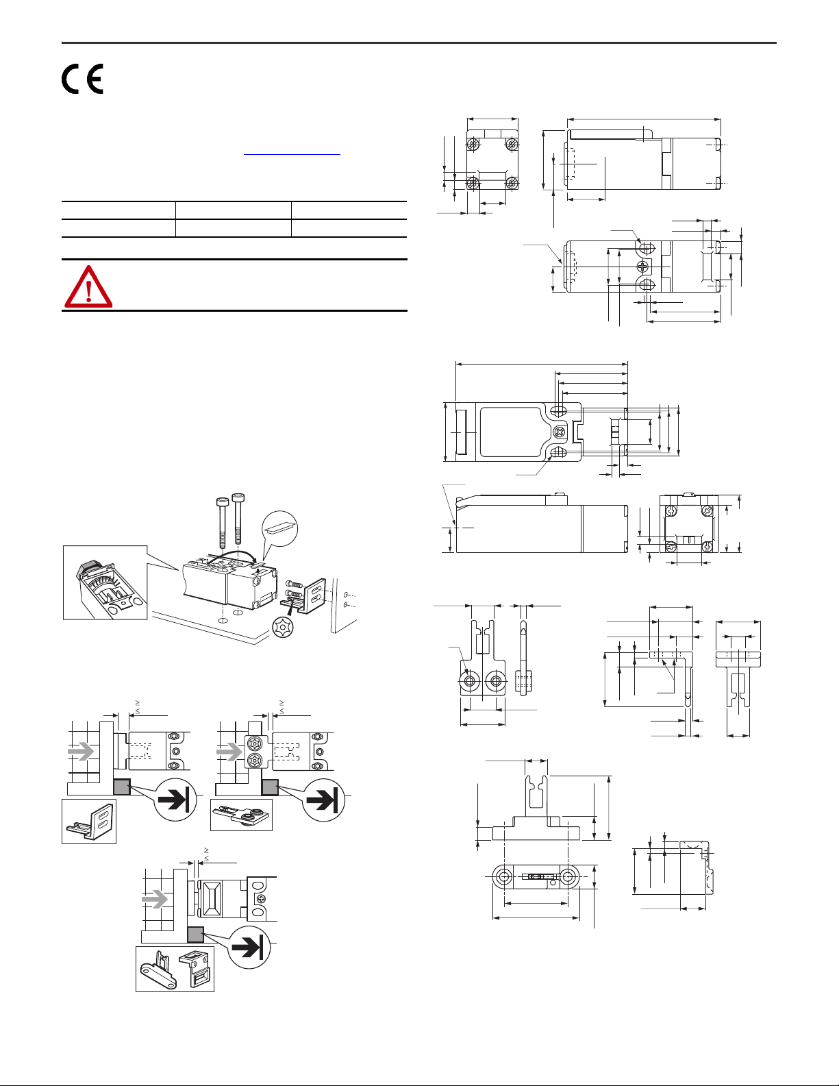
Mounting
Approximate Dimensions
Figure 1 - Elf Tongue Interlock Switch Dimensions [mm (in.)]
25 (0.98) 75 (2.95)
4 (0.16)
4.5 (0.18)
6 (0.24)
13 (0.51)
Figure 2 - Cadet 3 Tongue Interlock Switch Dimensions [mm (in.)]
31 (1.22)
1 x M16
1 x M16
90.5 (3.56)
2 x M4
29 (1.14)
12.5 (0.49)
12.5
(0.49)
17.5 (0.69)
38.4 (1.51)
36.4 (1.43)
34.4 (1.35)
2 x M4
18 (0.71)
16.5 (0.65)
13
(0.51)
3 (0.12)
4.5 (0.18)
4 (0.16)
4 (0.16)
4.5 (0.18)
34.5 (1.36)
36 (1.42)
20 (0.79)
22 (0.87)
25 (0.98)
6 (0.24)
13 (0.51)
Key Placement
13
(0.51)
Figure 3 - Key Dimensions [mm (in.)]
12 (0.47)
M4
25 (0.59)
Cat. No. 440K-A21014
12 (0.47)
8.5 (0.33)
Cat. No. 440K-A21030
3 (0.12)
15 (0.98)
40 (1.57)
55.5 (2.19)
14 (0.55)
40 (1.57)
15.5 (0.61)
4 (0.16)
4.5 (0.18)
25 (0.98)
3 (0.12)
13.5 (0.53)
4 (0.16)
13 (0.51)
30.4 (1.2)
25 (0.98)
2 Rockwell Automation Publication 440K-IN001D-EN-P - July 2020
Page 3

Head Rotation
0.57 N•m (5.04 lb•in)
B
D
C
A
1112
2324
2
1
1
3
2
4
3
4
1112
2122
2
1
1
3
2
4
3
4
1112
2122
3334
1
5
1
5
2
6
3
4
6
2
4
3
1112
2122
3132
1
5
2
6
3
4
1
5
6
2
4
3
Elf QD Elf QD Cadet 3 QD Cadet 3 QD
1112
2324
1112
2122
1112
2122
3334
1112
2122
3132
Cadet 3Elf Cadet 3Elf
1112
2122
1
2
4
5
1112
2122
1
2
4
5
3132
Safety C
2
5
1
3
4
Safety A
Safety A
N/A
Safety B
Safety B
5-pin Micro (M12)
for ArmorBlock® Guard I/O™
Cadet 3Elf
=
=
3.8
4.2
11/12
23/24
0 mm6
=
=
4
11/12
21/22
0 mm6
=
=
3.8
11/12
21/22
0 mm
4.5
33/34
=
=
3.8
11/12
21/22
0 mm
3.3
33/34
=
=
3.8
11/12
21/22
0 mm
31/32
Cadet 3Elf Cadet 3 Cadet 3Elf
Pinouts
Elf and Cadet 3 Tongue Interlock Switches Installation Instructions
Wiring
ATTENTION: Improper selection or installation of the devices affects the integrity of the safety systems.
Personnel injury or death, property damage or economic loss can result.
Comply with ISO 14119 including selection, accessibility to the installation, arrangement and fastening, possible substitute actuation, motivation to
defeat, and actuation mode.
Management controls, working procedures, training, and additional protective measures should be used to minimize the motivation to defeat and to
manage the use and availability of spare actuators.
Comply with IEC 62061 or ISO 13849-1 and ISO 13849-2 for functional safety.
Comply with ISO 13857 and ISO 13855 for guard openings and minimum (safe) distances.
Rockwell Automation Publication 440K-IN001D-EN-P - July 2020 3
Page 4

Rockwell Automation Support
Use these resources to access support information.
Technical Support Center Find help with how-to videos, FAQs, chat, user forums, and product notification updates. rok.auto/support
Knowledgebase Access Knowledgebase articles. rok.auto/knowledgebase
Local Technical Support Phone Numbers Locate the telephone number for your country. rok.auto/phonesupport
Literature Library Find installation instructions, manuals, brochures, and technical data publications. rok.auto/literature
Product Compatibility and Download Center
(PCDC)
Download firmware, associated files (such as AOP, EDS, and DTM), and access product
release notes.
rok.auto/pcdc
Documentation Feedback
Your comments help us serve your documentation needs better. If you have any suggestions on how to improve our content, complete the form at rok.auto/docfeedback.
Waste Electrical and Electronic Equipment (WEEE)
At the end of life, this equipment should be collected separately from any unsorted municipal waste.
Rockwell Automation maintains current product environmental compliance information on its website at rok.auto/pec.
Your comments help us serve your documentation needs better. If you have any suggestions on how to improve our content, complete the form at rok.auto/docfeedback.
For technical support, visit rok.auto/support.
Rockwell Otomasyon Ticaret A.Ş. Kar Plaza İş Merkezi E Blok Kat:6 34752 İçerenköy, İstanbul, Tel: +90 (216) 5698400 EEE Yönetmeliğine Uygundur
Allen-Bradley, ArmorBlock, expanding human possibility, Cadet, Elf, Guard I/O, Guardmaster, and Rockwell Automation are trademarks of
Rockwell Automation, Inc.
Trademarks not belonging to Rockwell Automation are property of their respective companies.
Publication 440K-IN001D-EN-P - July 2020 | Supersedes Publication 440K-IN001C-EN-P-August 2019
Copyright © 2020 Rockwell Automation, Inc. All rights reserved. Printed in the U.S.A.
PN-462122
W21687 Ver 09
 Loading...