

Page 1

User Manual
E3 & E3 Plus Solid-State Overload Relay
Catalog Numbers
193/592-EC1, -EC2, -EC3, -EC5
Page 2
Important User Information
IMPORTANT
Solid-state equipment has operational characteristics differing from those of electromechanical equipment. Safety
Guidelines for the Application, Installation and Maintenance of Solid State Controls (publication SGI-1.1
your local Rockwell Automation sales office or online at http://www.rockwellautomation.com/literature/
important differences between solid-state equipment and hard-wired electromechanical devices. Because of this difference,
and also because of the wide variety of uses for solid-state equipment, all persons responsible for applying this equipment
must satisfy themselves that each intended application of this equipment is acceptable.
In no event will Rockwell Automation, Inc. be responsible or liable for indirect or consequential damages resulting from
the use or application of this equipment.
The examples and diagrams in this manual are included solely for illustrative purposes. Because of the many variables and
requirements associated with any particular installation, Rockwell Automation, Inc. cannot assume responsibility or
liability for actual use based on the examples and diagrams.
No patent liability is assumed by Rockwell Automation, Inc. with respect to use of information, circuits, equipment, or
software described in this manual.
Reproduction of the contents of this manual, in whole or in part, without written permission of Rockwell Automation,
Inc., is prohibited.
Throughout this manual, when necessary, we use notes to make you aware of safety considerations.
WARNING: Identifies information about practices or circumstances that can cause an explosion in a hazardous
environment, which may lead to personal injury or death, property damage, or economic loss.
available from
) describes some
ATTENTION: Identifies information about practices or circumstances that can lead to personal injury or death,
property damage, or economic loss. Attentions help you identify a hazard, avoid a hazard, and recognize the
consequence
SHOCK HAZARD: Labels may be on or inside the equipment, for example, a drive or motor, to alert people that
dangerous voltage may be present.
BURN HAZARD: Labels may be on or inside the equipment, for example, a drive or motor, to alert people that
surfaces may reach dangerous temperatures.
Identifies information that is critical for successful application and understanding of the product.
Allen-Bradley, Rockwell Software, Rockwell Automation, and TechConnect are trademarks of Rockwell Automation, Inc.
Trademarks not belonging to Rockwell Automation are property of their respective companies.
Page 3

Table of Contents
Manual Objectives . . . . . . . . . . . . . . . . . . . . . . . . . . . . . . . . . . . . . . . . . . . . . . . . 9
Who Should Use This Manual . . . . . . . . . . . . . . . . . . . . . . . . . . . . . . . . . . . . . 9
Vocabulary. . . . . . . . . . . . . . . . . . . . . . . . . . . . . . . . . . . . . . . . . . . . . . . . . . . . . . . . 9
Conventions . . . . . . . . . . . . . . . . . . . . . . . . . . . . . . . . . . . . . . . . . . . . . . . . . . . . . . 9
Reference Manuals . . . . . . . . . . . . . . . . . . . . . . . . . . . . . . . . . . . . . . . . . . . . . . . . 9
Product Overview
Installation & Wiring
Introduction . . . . . . . . . . . . . . . . . . . . . . . . . . . . . . . . . . . . . . . . . . . . . . . . . . . . . 11
Description . . . . . . . . . . . . . . . . . . . . . . . . . . . . . . . . . . . . . . . . . . . . . . . . . . . . . . 11
Catalog Number Explanation . . . . . . . . . . . . . . . . . . . . . . . . . . . . . . . . . . . . . 12
Single-/Three-Phase Operation. . . . . . . . . . . . . . . . . . . . . . . . . . . . . . . . . . . . 12
Protection & Warning Functions. . . . . . . . . . . . . . . . . . . . . . . . . . . . . . . . . . 12
Parameter Monitoring . . . . . . . . . . . . . . . . . . . . . . . . . . . . . . . . . . . . . . . . . . . . 13
Current-Based Operational Data . . . . . . . . . . . . . . . . . . . . . . . . . . . . . . 13
Diagnostic Parameters . . . . . . . . . . . . . . . . . . . . . . . . . . . . . . . . . . . . . . . . 13
Voltage Parameters . . . . . . . . . . . . . . . . . . . . . . . . . . . . . . . . . . . . . . . . . . . 13
Power Parameters. . . . . . . . . . . . . . . . . . . . . . . . . . . . . . . . . . . . . . . . . . . . . 13
Overload Relay Features . . . . . . . . . . . . . . . . . . . . . . . . . . . . . . . . . . . . . . . . . . 14
Trip Relay . . . . . . . . . . . . . . . . . . . . . . . . . . . . . . . . . . . . . . . . . . . . . . . . . . . 14
Inputs & Outputs . . . . . . . . . . . . . . . . . . . . . . . . . . . . . . . . . . . . . . . . . . . . 14
User Interface . . . . . . . . . . . . . . . . . . . . . . . . . . . . . . . . . . . . . . . . . . . . . . . . 15
DeviceNet Compatibility . . . . . . . . . . . . . . . . . . . . . . . . . . . . . . . . . . . . . 16
Flash Memory . . . . . . . . . . . . . . . . . . . . . . . . . . . . . . . . . . . . . . . . . . . . . . . . 16
Introduction . . . . . . . . . . . . . . . . . . . . . . . . . . . . . . . . . . . . . . . . . . . . . . . . . . . . . 17
Receiving . . . . . . . . . . . . . . . . . . . . . . . . . . . . . . . . . . . . . . . . . . . . . . . . . . . . . . . . 17
Unpacking/Inspecting . . . . . . . . . . . . . . . . . . . . . . . . . . . . . . . . . . . . . . . . . . . . 17
Storing . . . . . . . . . . . . . . . . . . . . . . . . . . . . . . . . . . . . . . . . . . . . . . . . . . . . . . . . . . 17
General Precautions . . . . . . . . . . . . . . . . . . . . . . . . . . . . . . . . . . . . . . . . . . . . . . 18
Starter Assembly . . . . . . . . . . . . . . . . . . . . . . . . . . . . . . . . . . . . . . . . . . . . . . . . . 18
Installation. . . . . . . . . . . . . . . . . . . . . . . . . . . . . . . . . . . . . . . . . . . . . . . . . . . 18
Approximate Dimensions . . . . . . . . . . . . . . . . . . . . . . . . . . . . . . . . . . . . . 21
Separate Panel Adapter . . . . . . . . . . . . . . . . . . . . . . . . . . . . . . . . . . . . . . . . . . . 24
Approximate Dimensions . . . . . . . . . . . . . . . . . . . . . . . . . . . . . . . . . . . . . 24
Voltage Input Module . . . . . . . . . . . . . . . . . . . . . . . . . . . . . . . . . . . . . . . . . . . . 26
Specifications . . . . . . . . . . . . . . . . . . . . . . . . . . . . . . . . . . . . . . . . . . . . . . . . . . . . 26
Power Terminals . . . . . . . . . . . . . . . . . . . . . . . . . . . . . . . . . . . . . . . . . . . . . 26
Three-Pole Terminal Blocks . . . . . . . . . . . . . . . . . . . . . . . . . . . . . . . . . . . 27
Terminal Lug Kits . . . . . . . . . . . . . . . . . . . . . . . . . . . . . . . . . . . . . . . . . . . . 27
Control, DeviceNet, & Voltage Input Module Terminals . . . . . . . . 27
Terminal Designations. . . . . . . . . . . . . . . . . . . . . . . . . . . . . . . . . . . . . . . . . . . . 29
Control Terminals. . . . . . . . . . . . . . . . . . . . . . . . . . . . . . . . . . . . . . . . . . . . 29
DeviceNet Terminals . . . . . . . . . . . . . . . . . . . . . . . . . . . . . . . . . . . . . . . . . 29
Grounding. . . . . . . . . . . . . . . . . . . . . . . . . . . . . . . . . . . . . . . . . . . . . . . . . . . . . . . 29
Short-Circuit Ratings. . . . . . . . . . . . . . . . . . . . . . . . . . . . . . . . . . . . . . . . . . . . . 30
Short-Circuit Ratings . . . . . . . . . . . . . . . . . . . . . . . . . . . . . . . . . . . . . . . . . 30
High-Fault Short-Circuit Ratings . . . . . . . . . . . . . . . . . . . . . . . . . . . . . . 31
Fuse Coordination . . . . . . . . . . . . . . . . . . . . . . . . . . . . . . . . . . . . . . . . . . . . . . . 32
Rockwell Automation Publication 193-UM002I-EN-P - December 2011 3
Page 4

Typical Motor Connections. . . . . . . . . . . . . . . . . . . . . . . . . . . . . . . . . . . . . . . 34
Three-Phase Direct On-Line (DOL) & Single-Phase Full Voltage 34
External Line Current Transformer Application . . . . . . . . . . . . . . . . . . . . 34
Specifications . . . . . . . . . . . . . . . . . . . . . . . . . . . . . . . . . . . . . . . . . . . . . . . . 34
Installation Requirements . . . . . . . . . . . . . . . . . . . . . . . . . . . . . . . . . . . . . 35
External Potential Transformer (PT) Connection . . . . . . . . . . . . . . . 36
Core Balanced Ground Fault Sensor Application. . . . . . . . . . . . . . . . 37
Typical Control Circuit. . . . . . . . . . . . . . . . . . . . . . . . . . . . . . . . . . . . . . . . . . . 41
Wiring Diagrams . . . . . . . . . . . . . . . . . . . . . . . . . . . . . . . . . . . . . . . . . . . . . 41
External/Remote Reset (FRN 3.001 & Later) . . . . . . . . . . . . . . . . . . . 44
Protective Trip & Warning
Functions
Introduction . . . . . . . . . . . . . . . . . . . . . . . . . . . . . . . . . . . . . . . . . . . . . . . . . . . . . 45
Trip Enable . . . . . . . . . . . . . . . . . . . . . . . . . . . . . . . . . . . . . . . . . . . . . . . . . . . . . . 45
Warning Enable. . . . . . . . . . . . . . . . . . . . . . . . . . . . . . . . . . . . . . . . . . . . . . . . . . 45
Overload Protection . . . . . . . . . . . . . . . . . . . . . . . . . . . . . . . . . . . . . . . . . . . . . . 45
Overload Trip. . . . . . . . . . . . . . . . . . . . . . . . . . . . . . . . . . . . . . . . . . . . . . . . 45
FLA Setting . . . . . . . . . . . . . . . . . . . . . . . . . . . . . . . . . . . . . . . . . . . . . . . . . . 46
CT Ratio . . . . . . . . . . . . . . . . . . . . . . . . . . . . . . . . . . . . . . . . . . . . . . . . . . . . 47
Trip Class. . . . . . . . . . . . . . . . . . . . . . . . . . . . . . . . . . . . . . . . . . . . . . . . . . . . 47
Trip Curves . . . . . . . . . . . . . . . . . . . . . . . . . . . . . . . . . . . . . . . . . . . . . . . . . . 47
Auto/Manual Reset. . . . . . . . . . . . . . . . . . . . . . . . . . . . . . . . . . . . . . . . . . . 49
Overload Warning. . . . . . . . . . . . . . . . . . . . . . . . . . . . . . . . . . . . . . . . . . . . 50
Overload Diagnostics . . . . . . . . . . . . . . . . . . . . . . . . . . . . . . . . . . . . . . . . . 51
Non-Volatile Thermal Memory. . . . . . . . . . . . . . . . . . . . . . . . . . . . . . . . 51
Phase Loss Protection. . . . . . . . . . . . . . . . . . . . . . . . . . . . . . . . . . . . . . . . . . . . . 51
Phase Loss Trip. . . . . . . . . . . . . . . . . . . . . . . . . . . . . . . . . . . . . . . . . . . . . . . 51
Ground Fault Protection (E3 Plus) . . . . . . . . . . . . . . . . . . . . . . . . . . . . . . . . 52
Ground Fault Setting Range . . . . . . . . . . . . . . . . . . . . . . . . . . . . . . . . . . . 53
Ground Fault Trip. . . . . . . . . . . . . . . . . . . . . . . . . . . . . . . . . . . . . . . . . . . . 53
Ground Fault Trip Inhibit . . . . . . . . . . . . . . . . . . . . . . . . . . . . . . . . . . . . 54
Ground Fault Warning . . . . . . . . . . . . . . . . . . . . . . . . . . . . . . . . . . . . . . . 55
Ground Fault Filter . . . . . . . . . . . . . . . . . . . . . . . . . . . . . . . . . . . . . . . . . . . 55
Stall Protection . . . . . . . . . . . . . . . . . . . . . . . . . . . . . . . . . . . . . . . . . . . . . . . . . . 56
Stall Time. . . . . . . . . . . . . . . . . . . . . . . . . . . . . . . . . . . . . . . . . . . . . . . . . . . . 56
Jam Protection (High Overload). . . . . . . . . . . . . . . . . . . . . . . . . . . . . . . . . . . 57
Jam Trip . . . . . . . . . . . . . . . . . . . . . . . . . . . . . . . . . . . . . . . . . . . . . . . . . . . . . 57
Jam Warning. . . . . . . . . . . . . . . . . . . . . . . . . . . . . . . . . . . . . . . . . . . . . . . . . 58
Underload Protection . . . . . . . . . . . . . . . . . . . . . . . . . . . . . . . . . . . . . . . . . . . . 58
Underload Trip . . . . . . . . . . . . . . . . . . . . . . . . . . . . . . . . . . . . . . . . . . . . . . 58
Underload Warning . . . . . . . . . . . . . . . . . . . . . . . . . . . . . . . . . . . . . . . . . . 59
PTC Trip . . . . . . . . . . . . . . . . . . . . . . . . . . . . . . . . . . . . . . . . . . . . . . . . . . . . 61
PTC Warning. . . . . . . . . . . . . . . . . . . . . . . . . . . . . . . . . . . . . . . . . . . . . . . . 62
Current Imbalance Protection. . . . . . . . . . . . . . . . . . . . . . . . . . . . . . . . . . . . . 62
Current Imbalance Trip. . . . . . . . . . . . . . . . . . . . . . . . . . . . . . . . . . . . . . . 62
Current Imbalance Warning . . . . . . . . . . . . . . . . . . . . . . . . . . . . . . . . . . 63
Communication Fault Protection
. . . . . . . . . . . . . . . . . . . . . . . . . . . . . . . . . 64
4 Rockwell Automation Publication 193-UM002I-EN-P - December 2011
Page 5

Comm Fault Trip . . . . . . . . . . . . . . . . . . . . . . . . . . . . . . . . . . . . . . . . . . . . 64
Comm Fault Warning . . . . . . . . . . . . . . . . . . . . . . . . . . . . . . . . . . . . . . . . 65
Communication Idle Protection. . . . . . . . . . . . . . . . . . . . . . . . . . . . . . . . . . . 65
Comm Idle Trip. . . . . . . . . . . . . . . . . . . . . . . . . . . . . . . . . . . . . . . . . . . . . . 65
Comm Idle Warning. . . . . . . . . . . . . . . . . . . . . . . . . . . . . . . . . . . . . . . . . . 66
Remote Trip . . . . . . . . . . . . . . . . . . . . . . . . . . . . . . . . . . . . . . . . . . . . . . . . . 66
Voltage Protection . . . . . . . . . . . . . . . . . . . . . . . . . . . . . . . . . . . . . . . . . . . . . . . 67
Under Voltage (UV) Trip . . . . . . . . . . . . . . . . . . . . . . . . . . . . . . . . . . . . . 67
Under Voltage (UV) Warning . . . . . . . . . . . . . . . . . . . . . . . . . . . . . . . . . 68
Over Voltage (OV) Trip . . . . . . . . . . . . . . . . . . . . . . . . . . . . . . . . . . . . . . 68
Over Voltage (OV) Warning . . . . . . . . . . . . . . . . . . . . . . . . . . . . . . . . . . 69
Voltage Unbalance Protection. . . . . . . . . . . . . . . . . . . . . . . . . . . . . . . . . . . . . 69
Voltage Unbalance Trip. . . . . . . . . . . . . . . . . . . . . . . . . . . . . . . . . . . . . . . 69
Voltage Unbalance Warning. . . . . . . . . . . . . . . . . . . . . . . . . . . . . . . . . . . 70
Voltage Rotation Protection. . . . . . . . . . . . . . . . . . . . . . . . . . . . . . . . . . . . . . . 71
Voltage Rotation Trip . . . . . . . . . . . . . . . . . . . . . . . . . . . . . . . . . . . . . . . . 71
Voltage Rotation Warning . . . . . . . . . . . . . . . . . . . . . . . . . . . . . . . . . . . . 71
Frequency Protection . . . . . . . . . . . . . . . . . . . . . . . . . . . . . . . . . . . . . . . . . . . . . 72
Under Frequency (UF) Trip. . . . . . . . . . . . . . . . . . . . . . . . . . . . . . . . . . . 72
Under Frequency Warning . . . . . . . . . . . . . . . . . . . . . . . . . . . . . . . . . . . . 72
Over Frequency (OF) Trip . . . . . . . . . . . . . . . . . . . . . . . . . . . . . . . . . . . . 73
Over Frequency (OF) Warning . . . . . . . . . . . . . . . . . . . . . . . . . . . . . . . . 73
Voltage Input Module Detection . . . . . . . . . . . . . . . . . . . . . . . . . . . . . . . . . . 74
Voltage Hardware Trip . . . . . . . . . . . . . . . . . . . . . . . . . . . . . . . . . . . . . . . 74
Voltage Hardware Warning . . . . . . . . . . . . . . . . . . . . . . . . . . . . . . . . . . . 74
Real Power (kW) Protection . . . . . . . . . . . . . . . . . . . . . . . . . . . . . . . . . . . . . . 75
Under Real Power Trip . . . . . . . . . . . . . . . . . . . . . . . . . . . . . . . . . . . . . . . 75
Under Real Power Warning . . . . . . . . . . . . . . . . . . . . . . . . . . . . . . . . . . . 75
Over Real Power Trip. . . . . . . . . . . . . . . . . . . . . . . . . . . . . . . . . . . . . . . . . 76
Over Real Power Warning. . . . . . . . . . . . . . . . . . . . . . . . . . . . . . . . . . . . . 76
Reactive Power (kVAR) Protection . . . . . . . . . . . . . . . . . . . . . . . . . . . . . . . . 77
Under Reactive Power Consumed Trip. . . . . . . . . . . . . . . . . . . . . . . . . 77
Under Reactive Power Consumed Warning . . . . . . . . . . . . . . . . . . . . 78
Over Reactive Power Consumed Trip . . . . . . . . . . . . . . . . . . . . . . . . . . 78
Over Reactive Power Consumed Warning . . . . . . . . . . . . . . . . . . . . . . 79
Under Reactive Power Generated Trip . . . . . . . . . .
. . . . . . . . . . . . . . . 79
Under Reactive Power Generated Warning . . . . . . . . . . . . . . . . . . . . . 80
Over Reactive Power Generated Trip. . . . . . . . . . . . . . . . . . . . . . . . . . . 80
Over Reactive Power Generated Warning . . . . . . . . . . . . . . . . . . . . . . 81
Apparent Power (kVA) Protection. . . . . . . . . . . . . . . . . . . . . . . . . . . . . . . . . 81
Under Apparent Power Trip . . . . . . . . . . . . . . . . . . . . . . . . . . . . . . . . . . 82
Under Apparent Power Warning . . . . . . . . . . . . . . . . . . . . . . . . . . . . . . 82
Over Apparent Power Trip . . . . . . . . . . . . . . . . . . . . . . . . . . . . . . . . . . . . 83
Over Apparent Power Warning. . . . . . . . . . . . . . . . . . . . . . . . . . . . . . . . 83
Power Factor Protection . . . . . . . . . . . . . . . . . . . . . . . . . . . . . . . . . . . . . . . . . . 84
Under Power Factor Lagging Trip . . . . . . . . . . . . . . . . . . . . . . . . . . . . . 84
Rockwell Automation Publication 193-UM002I-EN-P - December 2011 5
Page 6

Under Power Factor Lagging Warning . . . . . . . . . . . . . . . . . . . . . . . . . 85
Over Power Factor Lagging Trip . . . . . . . . . . . . . . . . . . . . . . . . . . . . . . . 85
Over Power Factor Lagging Warning. . . . . . . . . . . . . . . . . . . . . . . . . . . 86
Under Power Factor Leading Trip . . . . . . . . . . . . . . . . . . . . . . . . . . . . . 86
Under Power Factor Leading Warning . . . . . . . . . . . . . . . . . . . . . . . . . 87
Over Power Factor Leading Trip. . . . . . . . . . . . . . . . . . . . . . . . . . . . . . . 87
Over Power Factor Leading Warning. . . . . . . . . . . . . . . . . . . . . . . . . . . 88
Protective Trip & Warning Summary . . . . . . . . . . . . . . . . . . . . . . . . . . . . . . 88
Preventive Maintenance Diagnostics (E3 Overload Relays Series C &
Later) . . . . . . . . . . . . . . . . . . . . . . . . . . . . . . . . . . . . . . . . . . . . . . . . . . . . . . . . . . . 91
Monitoring . . . . . . . . . . . . . . . . . . . . . . . . . . . . . . . . . . . . . . . . . . . . . . . . . . 91
Start Inhibit. . . . . . . . . . . . . . . . . . . . . . . . . . . . . . . . . . . . . . . . . . . . . . . . . . 91
Start Inhibit Trip . . . . . . . . . . . . . . . . . . . . . . . . . . . . . . . . . . . . . . . . . . . . . 91
Preventive Maintenance Flags . . . . . . . . . . . . . . . . . . . . . . . . . . . . . . . . . 92
Queue Clearing. . . . . . . . . . . . . . . . . . . . . . . . . . . . . . . . . . . . . . . . . . . . . . . 93
DeviceNet™ Node
Commissioning
Programmable Parameters
Monitoring Parameters
Introduction . . . . . . . . . . . . . . . . . . . . . . . . . . . . . . . . . . . . . . . . . . . . . . . . . . . . . 95
Setting the Hardware Switches (Series B & Later) . . . . . . . . . . . . . . . 95
Using RSNetWorx for DeviceNet. . . . . . . . . . . . . . . . . . . . . . . . . . . . . . 96
Commissioning the Protection Functions . . . . . . . . . . . . . . . . . . . . . . . . . 103
Introduction . . . . . . . . . . . . . . . . . . . . . . . . . . . . . . . . . . . . . . . . . . . . . . . . . . . . 105
Programming . . . . . . . . . . . . . . . . . . . . . . . . . . . . . . . . . . . . . . . . . . . . . . . . . . . 105
Program Lock . . . . . . . . . . . . . . . . . . . . . . . . . . . . . . . . . . . . . . . . . . . . . . . 105
Reset to Default Factory Settings. . . . . . . . . . . . . . . . . . . . . . . . . . . . . . 105
Parameter Group Listing. . . . . . . . . . . . . . . . . . . . . . . . . . . . . . . . . . . . . . . . . 105
Overload Setup Group . . . . . . . . . . . . . . . . . . . . . . . . . . . . . . . . . . . . . . . 111
Advanced Setup Group . . . . . . . . . . . . . . . . . . . . . . . . . . . . . . . . . . . . . . 114
Reset/Lock Group. . . . . . . . . . . . . . . . . . . . . . . . . . . . . . . . . . . . . . . . . . . . . . . 123
DeviceNet Setup Group. . . . . . . . . . . . . . . . . . . . . . . . . . . . . . . . . . . . . . 125
Output Setup Group. . . . . . . . . . . . . . . . . . . . . . . . . . . . . . . . . . . . . . . . . 127
DeviceLogix Group — E3 Plus. . . . . . . . . . . . . . . . . . . . . . . . . . . . . . . . 131
Introduction . . . . . . . . . . . . . . . . . . . . . . . . . . . . . . . . . . . . . . . . . . . . . . . . . . . . 135
Phase Current Reporting. . . . . . . . . . . . . . . . . . . . . . . . . . . . . . . . . . . . . . . . . 135
Current Range . . . . . . . . . . . . . . . . . . . . . . . . . . . . . . . . . . . . . . . . . . . . . . 135
Reporting Accuracy. . . . . . . . . . . . . . . . . . . . . . . . . . . . . . . . . . . . . . . . . . 136
Ground Fault Current Reporting . . . . . . . . . . . . . . . . . . . . . . . . . . . . . . . . . 137
Current Range . . . . . . . . . . . . . . . . . . . . . . . . . . . . . . . . . . . . . . . . . . . . . . 137
Frequency Range . . . . . . . . . . . . . . . . . . . . . . . . . . . . . . . . . . . . . . . . . . . . 137
Diagnostic Parameters . . . . . . . . . . . . . . . . . . . . . . . . . . . . . . . . . . . . . . . . . . . 137
Monitor Group . . . . . . . . . . . . . . . . . . . . . . . . . . . . . . . . . . . . . . . . . . . . . . . . . 138
Voltage Parameters
6 Rockwell Automation Publication 193-UM002I-EN-P - December 2011
Introduction . . . . . . . . . . . . . . . . . . . . . . . . . . . . . . . . . . . . . . . . . . . . . . . . . . . . 147
Phase Voltage Reporting . . . . . . . . . . . . . . . . . . . . . . . . . . . . . . . . . . . . . . . . . 147
Page 7

Voltage Range . . . . . . . . . . . . . . . . . . . . . . . . . . . . . . . . . . . . . . . . . . . . . . . 147
Voltage Accuracy . . . . . . . . . . . . . . . . . . . . . . . . . . . . . . . . . . . . . . . . . . . . 148
Voltage Monitor Group. . . . . . . . . . . . . . . . . . . . . . . . . . . . . . . . . . . . . . . . . . 148
Voltage Setup Group . . . . . . . . . . . . . . . . . . . . . . . . . . . . . . . . . . . . . . . . . . . . 151
Power Parameters
Trip History and Snapshot
Logic Controller
Communication Examples
Introduction . . . . . . . . . . . . . . . . . . . . . . . . . . . . . . . . . . . . . . . . . . . . . . . . . . . . 159
Phase Power Reporting . . . . . . . . . . . . . . . . . . . . . . . . . . . . . . . . . . . . . . . . . . 159
Power Range . . . . . . . . . . . . . . . . . . . . . . . . . . . . . . . . . . . . . . . . . . . . . . . . 159
Power Accuracy . . . . . . . . . . . . . . . . . . . . . . . . . . . . . . . . . . . . . . . . . . . . . 161
Power Monitor Group. . . . . . . . . . . . . . . . . . . . . . . . . . . . . . . . . . . . . . . . . . . 161
Power Setup Group. . . . . . . . . . . . . . . . . . . . . . . . . . . . . . . . . . . . . . . . . . . . . . 171
Trip and Warning History . . . . . . . . . . . . . . . . . . . . . . . . . . . . . . . . . . . . . . . 183
TripWarn History Group . . . . . . . . . . . . . . . . . . . . . . . . . . . . . . . . . . . . 183
Trip Snapshot. . . . . . . . . . . . . . . . . . . . . . . . . . . . . . . . . . . . . . . . . . . . . . . . . . . 189
Trip Snapshot Group . . . . . . . . . . . . . . . . . . . . . . . . . . . . . . . . . . . . . . . . 190
Introduction . . . . . . . . . . . . . . . . . . . . . . . . . . . . . . . . . . . . . . . . . . . . . . . . . . . . 193
I/O Messaging . . . . . . . . . . . . . . . . . . . . . . . . . . . . . . . . . . . . . . . . . . . . . . . . . . 193
Explicit Messaging. . . . . . . . . . . . . . . . . . . . . . . . . . . . . . . . . . . . . . . . . . . . . . . 195
Reading Device Status using the Parameter Object Class (0x0F) . 195
Reading Device Status using the Control Supervisor Object Class
(0x29) . . . . . . . . . . . . . . . . . . . . . . . . . . . . . . . . . . . . . . . . . . . . . . . . . . . . . . 197
Reading the Trip Class using the Overload Object Class (0x2C). 199
Reading a Group of Parameters using the E3 Status Object Class
(0x0375). . . . . . . . . . . . . . . . . . . . . . . . . . . . . . . . . . . . . . . . . . . . . . . . . . . . 201
Using DeviceLogix™
Troubleshooting
Introduction . . . . . . . . . . . . . . . . . . . . . . . . . . . . . . . . . . . . . . . . . . . . . . . . . . . . 205
DeviceLogix Programming . . . . . . . . . . . . . . . . . . . . . . . . . . . . . . . . . . . . . . . 206
DeviceLogix Programming Example. . . . . . . . . . . . . . . . . . . . . . . . . . . 206
Introduction . . . . . . . . . . . . . . . . . . . . . . . . . . . . . . . . . . . . . . . . . . . . . . . . . . . . 213
Advisory LEDs. . . . . . . . . . . . . . . . . . . . . . . . . . . . . . . . . . . . . . . . . . . . . . . . . . 213
Trip/Warn LED . . . . . . . . . . . . . . . . . . . . . . . . . . . . . . . . . . . . . . . . . . . . 213
Network Status LED. . . . . . . . . . . . . . . . . . . . . . . . . . . . . . . . . . . . . . . . . 215
OUT A & OUT B LEDs. . . . . . . . . . . . . . . . . . . . . . . . . . . . . . . . . . . . . 215
IN 1,2,3 & 4 LEDs. . . . . . . . . . . . . . . . . . . . . . . . . . . . . . . . . . . . . . . . . . . 215
Power-Up Sequence . . . . . . . . . . . . . . . . . . . . . . . . . . . . . . . . . . . . . . . . . . . . . 215
DeviceNet Modes of Operation . . . . . . . . . . . . . . . . . . . . . . . . . . . . . . . . . . 216
Power-Up Reset Mode . . . . . . . . . . . . . . . . . . . . . . . . . . . . . . . . . . . . . . . 216
Run Mode . . . . . . . . . . . . . . . . . . . . . . . . . . . . . . . . . . . . . . . . . . . . . . . . . . 216
Recoverable Error Mode . . . . . . . . . . . . . . . . . . . . . . . . . . . . . . . . . . . . . 217
Unrecoverable Error Mode . . . . . . . . . . . . . . . . . . . . . . . . . . . . . . . . . . . 217
Resetting a Trip . . . . . . . . . . . . . . . . . . . . . . . . . . . . . . . . . . . . . . . . . . . . . . . . . 217
Trip/Warn LED Troubleshooting Procedures. . . . . . . . . . . . . . . . . . . . . 218
Rockwell Automation Publication 193-UM002I-EN-P - December 2011 7
Page 8

DeviceNet Troubleshooting Procedures. . . . . . . . . . . . . . . . . . . . . . . . . . . 222
Loss of Node Address . . . . . . . . . . . . . . . . . . . . . . . . . . . . . . . . . . . . . . . . 222
Input and Output Troubleshooting Procedures. . . . . . . . . . . . . . . . . . . . 222
Specifications
DeviceNet™ Information
Electrical Specifications . . . . . . . . . . . . . . . . . . . . . . . . . . . . . . . . . . . . . . . . . . 225
Environmental Specifications . . . . . . . . . . . . . . . . . . . . . . . . . . . . . . . . . . . . 227
Electromagnetic Compatibility Specifications. . . . . . . . . . . . . . . . . . . . . . 227
Functionality Specifications . . . . . . . . . . . . . . . . . . . . . . . . . . . . . . . . . . . . . . 228
Protection . . . . . . . . . . . . . . . . . . . . . . . . . . . . . . . . . . . . . . . . . . . . . . . . . . . . . . 229
Electronic Data Sheets (EDS) . . . . . . . . . . . . . . . . . . . . . . . . . . . . . . . . . . . . 231
Product Codes . . . . . . . . . . . . . . . . . . . . . . . . . . . . . . . . . . . . . . . . . . . . . . . . . . 231
DeviceNet Objects . . . . . . . . . . . . . . . . . . . . . . . . . . . . . . . . . . . . . . . . . . . . . . 232
Identity Object – Class Code 0x01. . . . . . . . . . . . . . . . . . . . . . . . . . . . . . . . 233
Message Router – Class Code 0x02 . . . . . . . . . . . . . . . . . . . . . . . . . . . . . . . 234
DeviceNet Object – Class Code 0x03 . . . . . . . . . . . . . . . . . . . . . . . . . . . . . 234
Assembly Object – Class Code 0x04 . . . . . . . . . . . . . . . . . . . . . . . . . . . . . . 235
Output Assemblies . . . . . . . . . . . . . . . . . . . . . . . . . . . . . . . . . . . . . . . . . . . . . . 236
Input Assemblies . . . . . . . . . . . . . . . . . . . . . . . . . . . . . . . . . . . . . . . . . . . . . . . . 237
Connection Object – Class Code 0x05. . . . . . . . . . . . . . . . . . . . . . . . . . . . 239
Discrete Input Point Object – Class Code 0x08. . . . . . . . . . . . . . . . . . . . 243
Discrete Output Point Object – Class Code 0x09. . . . . . . . . . . . . . . . . . 243
Parameter Object – Class Code 0x0F . . . . . . . . . . . . . . . . . . . . . . . . . . . . . 244
Parameter Group Object – Class Code 0x10. . . . . . . . . . . . . . . . . . . . . . . 245
Discrete Output Group Object - CLASS CODE 0x001E . . . . . . . . . 246
Control Supervisor Object – Class Code 0x29 . . . . . . . . . . . . . . . . . . . . . 247
Control Supervisor ODVA Fault and Warning Codes . . . . . . . . . . 250
Acknowledge Handler Object – 0x2B. . . . . . . . . . . . . . . . . . . . . . . . . . . . . 251
Overload Object – Class Code 0x2C. . . . . . . . . . . . . . . . . . . . . . . . . . . . . . 251
DPI Fault Object - CLASS CODE 0x0097 . . . . . . . . . . . . . . . . . . . . . . . . 254
DPI Warning Object - CLASS CODE 0x0098 . . . . . . . . . . . . . . . . . . . . 257
DeviceNet Interface Object – Class Code 0xB4 . . . . . . . . . . . . . . . . . . . . 260
MCC Object - CLASS CODE 0x00C2 . . . . . . . . . . . . . . . . . . . . . . . . . . . 261
Logic Supervisor Object - CLASS CODE 0x030E . . . . . . . . . . . . . . . . . 261
E3 Status Object - CLASS CODE 0x0375 . . . . . . . . . . . . . . . . . . . . . . . . 262
CE Compliance
Two-Speed Applications
Accessories
8 Rockwell Automation Publication 193-UM002I-EN-P - December 2011
EC Directive Compliance. . . . . . . . . . . . . . . . . . . . . . . . . . . . . . . . . . . . . . . . 269
EMC Directive. . . . . . . . . . . . . . . . . . . . . . . . . . . . . . . . . . . . . . . . . . . . . . . . . . 269
Low Voltage Directive . . . . . . . . . . . . . . . . . . . . . . . . . . . . . . . . . . . . . . . . . . . 270
Introduction . . . . . . . . . . . . . . . . . . . . . . . . . . . . . . . . . . . . . . . . . . . . . . . . . . . . 271
External Control Applications. . . . . . . . . . . . . . . . . . . . . . . . . . . . . . . . . . . . 271
Output Control Applications . . . . . . . . . . . . . . . . . . . . . . . . . . . . . . . . . . . . 271
Accessories. . . . . . . . . . . . . . . . . . . . . . . . . . . . . . . . . . . . . . . . . . . . . . . . . . . . . . 273
Page 9

Preface
IMPORTANT
Manual Objectives
Who Should Use This Manual
Vocabulary
The purpose of this manual is to provide you with the necessary information to
apply the E3 Overload Relay with DeviceNet communications. Described in this
manual are methods for installing, configuring, and troubleshooting.
Read this manual in its entirety before installing, operating,
servicing, or initializing the E3 Overload Relay.
This manual is intended for qualified personnel responsible for setting up and
servicing these devices. You must have previous experience with and a basic
understanding of communications technology, configuration procedures,
required equipment, and safety precautions.
To make efficient use of the E3 Overload Relay, you must be able to program and
operate devices with communications and have a basic understanding of the E3
Overload Relay’s parameter settings and functions. You should also understand
DeviceNet network operations, including how slave devices operate on the
network and communicate with a DeviceNet master.
In this manual, we refer to the:
• E3 Overload Relay as it applies to both the E3 and E3 Plus Overload
Relays.
• E3 Plus Overload Relay when features and/or functions apply specifically
to it.
Conventions
Reference Manuals
Parameter names are shown in italic typeface.
E3 refers to the overload relays E3 and E3 Plus. “E3” is the standard version. “E3
Plus” is the enhanced version.
For SLC 500 and 1747-SDN information:
• DeviceNet Scanner Module Installation Instructions Publication
1747-IN058E-EN-P
• DeviceNet Scanner Module User Manual Publication
1747-UM655B-EN-P
For PLC5 and 1771-SDN information:
• DeviceNet Scanner Module Installation Instructions Publication 1771-5.14
• DeviceNet Scanner Module Configuration Manual Publication
1771-6.5.118
For MicroLogix/CompactLogic and 1769-ADN information:
Rockwell Automation Publication 193-UM002I-EN-P - December 2011 9
Page 10

Preface
IMPORTANT
• DeviceNet Module Installation Instructions Publication
1769-IN001B-EN-P
• DeviceNet Module User Manual Publication 1769-UM001B-EN-P
For ControlLogic and 1756-DNB information:
• DeviceNet Module Installation Instructions Publication
1756-IN566C-EN-P
• DeviceNet Module User Manual Publication DNET-UM004A-EN-P
To install and implement a DeviceNet network:
• DeviceNet Media Design and Installation Guide Publication
DNET-UM072_-EN-P
Read the DeviceNet Media Design and Installation Guide,
Publication DNET-UM072_-EN-P, in its entirety before
planning and installing a DeviceNet system. If the network is
not installed according to this document, unexpected
operation and intermittent failures can occur.
If this manual is not available, please contact either the local
Rockwell Automation Distributor or Sales Office and request
a copy. Electronic copies may also be obtained via the
Internet or from the Allen-Bradley Home Page at
“www.ab.com.”.
10 Rockwell Automation Publication 193-UM002I-EN-P - December 2011
Page 11
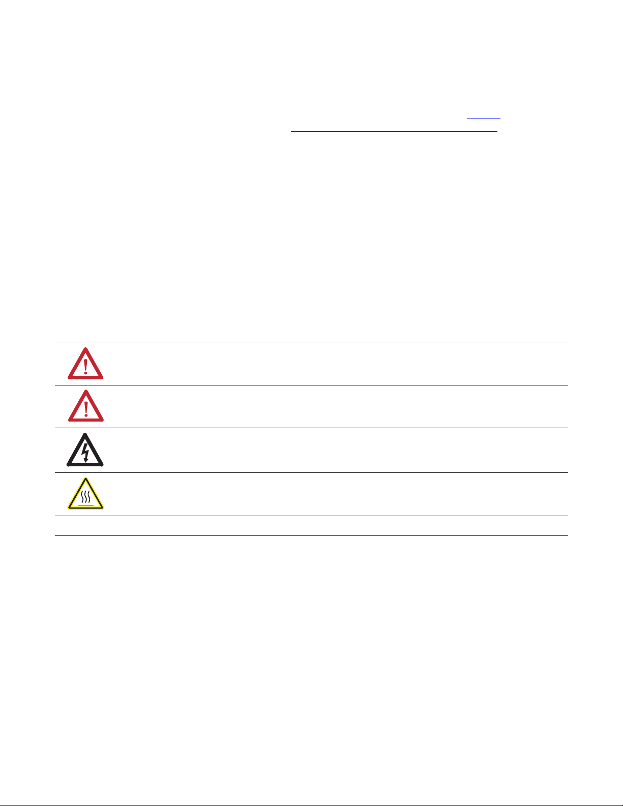
Product Overview
E3 PLUS
S1
S2
13 14 23 24 95 96 IT1 IT2
1 2 3 4 5 6
NETWORK
STATUS
OUT A
IN 1
IN 2
OUT B
IN 3
IN 4
MSD
LSD
TRIP
WARN
TEST/
RESET
DS/N
FRN
4.XXX
1AOXXXXX
XXX
SER
Test/Reset Button
Voltage Input Module
Connection
(193/592 EC5 only)
Ground Fault
Sensor Input
Output & PTC
Terminals
NOTE: On model EC5
devices, terminals IT1 and
IT2 are marked 7 and
8, respectively.
LED Status
Indicators
Node Address Switches
(series B and later)
DeviceNet Port
Input
Terminals
Chapter
1
Introduction
Description
This chapter provides a brief overview of the features and functionality of the E3
Overload Relay.
The E3 Overload Relay is a multi-function solid-state microprocessor-based
electronic overload relay for the protection of squirrel-cage induction motors
rated from 0.4…5,000 A. Four versions are available: the E3 model, EC1, and
E3Plus models EC2, EC3, and EC5.
Figure 1 - Front Panel Display (E3 Plus Overload Relay shown)
Rockwell Automation Publication 193-UM002I-EN-P - December 2011 11
Page 12

Chapter 1 Product Overview
193 - EC1 B B
592
Bulletin
Number
Type
EC1 E3
EC2 E3 Plus➊
EC3 E3 Plus➋
EC5 E3 Plus➋
Current Rating
(Amps)
P0.4…2.0
A1…5
B 3…15
C 5…25
D 9…45
E18…90
F28…140
G42…210
H60…302
J84…420
K 125…630
L 172…860
Bulletin 500
Contactor Size
T Size 00
C Size 0…2
D Size 3
E Size 4
F Size 5
G Size 6
Bulletin 100 Contactor
Size
B C09…C23
D C30…C43
E C60…C85
F D95…D180
G D210…D420
H D630…D860
ZPanel Mount, CT fed
➊ (0.4…90 A) Provides 1…5 A internal core-balanced ground fault protection
➋ (0.4.…5000 A) Provides 20 mA…5 A external core balanced ground fault protection. External ground fault
sensor required (Cat. nos. 193-CBCT-1…4).
Catalog Number Explanation
The solid-state overload relay purchased has its own catalog number. The catalog
number is explained below.
Single-/Three-Phase Operation
The overload relay is factory programmed for three-phase operation. The
installer can easily be changed to single-phase operation by accessing and
changing Single/Three Phase, Parameter 27. Refer to page 34 for typical motor
connections.
Protection & Warning Functions
12 Rockwell Automation Publication 193-UM002I-EN-P - December 2011
The E3 Overload Relay provides the following protection and warning functions:
Function Model
• Overload
• Phase loss (trip only)
• Stall (trip only)
• Jam
• Underload
• Current imbalance
• Number of starts (warning only)
• Operating hours (warning only)
• Voltage
• Power
• Frequency
• Ground fault EC2, EC3, & EC5 Only
• Thermistor (PTC) input EC2 and EC3 Only
Refer to Chapter 3 on page 45 for further explanation of these protection and
warning functions.
All Models
EC5 Only
Page 13

Product Overview Chapter 1
Parameter Monitoring
The E3 Overload Relay allows the user to monitor information on various
parameters over the DeviceNet™ network.
Current-Based Operational Data
Current-Based Operational Data Unit of Measure
Individual phase currents Amperes
Average current Amperes
Average current % of motor FLC
Percentage of thermal capacity utilized %
Current imbalance percentage %
Ground fault current (EC2, EC3, and EC5 only) Amperes
Refer to Chapter 6 for further information.
Diagnostic Parameters
• Device Status
• Trip S t atus
• Warning Status
• Time to an overload trip (in seconds)
• Time to reset after an overload trip (in
seconds)
• History of the past five trips and warnings
• Diagnostic data at the time of a trip
Refer to Chapter 6 for further information.
Voltage Parameters
• Voltage range
• Phase rotation
• Voltage warning status
Refer to Chapter 7 for further information.
• Voltage unbalance
• Voltage frequency
Power Parameters
• Power range
• Reactive power
• Apparent power
Refer to Chapter 8 for further information.
• Power factor
• Power consumed
Rockwell Automation Publication 193-UM002I-EN-P - December 2011 13
Page 14
Chapter 1 Product Overview
Overload Relay Features
Trip Relay
When the E3 Overload Relay is in the unpowered state, the trip relay contact is
open. The trip relay contact closes approximately 2 to 35 seconds after power is
applied if no trip condition exists.
Inputs & Outputs
In addition to the trip relay, the E3 Overload Relay provides inputs and outputs as
shown below.
Table 1 - Inputs & Outputs
Model Inputs ➊ Outputs
EC1 2 1
EC2, EC3 4 2
EC5 6 2
➊ Inputs are rated at 24V only. For 120V AC inputs, add the AC Input Interface Module, Cat. No. 193-EIMD.
The status of each input and output can be monitored over the DeviceNet
network through Device Status, Parameter 21, or one of the input assemblies.
Additionally, the outputs can be controlled over the network using one of the
output assemblies. Refer to Appendix B for listings of the available input and
output assemblies.
Series B and later E3 Plus Overload Relays offer added flexibility by providing the
capability to perform control functions with the inputs and outputs through
DeviceLogix™.
Series B or later E3 Overload Relay inputs are independently configurable for trip
reset, remote trip, two-speed, and normal operation.
ATTENTION: If the outputs are being commanded via an explicit
message, ensure that there is no established I/O connection that is
actively controlling the outputs and that the explicit message connection
has a non-zero expected packet rate (EPR) setting.
ATTENTION: The state of the outputs during a protection fault,
DeviceNet communication fault, or a DeviceNet communication idle may
be dependent on the following OUT A or OUT B parameters: PrFltState, Pr
FltValue, Dn FltState, Dn FltValue, Dn IdlState, and Dn IdlValue. For
details, refer to the Output Setup Group section in Chapter 5.
14 Rockwell Automation Publication 193-UM002I-EN-P - December 2011
Page 15

Product Overview Chapter 1
ATTENTION: The E3 Overload Relay’s output control firmware latches
OUT A and OUT B closed upon receipt of a network close command. The
outputs will maintain the commanded closed state until receipt of a
network open command. Parameters OutX Pr FltState and OutX Pr
FltValue, found in the E3 Overload Relay’s output setup group, allows
flexibility concerning the operation of the outputs in the event of a trip.
Factory default settings cause the outputs to open upon
occurrence of a trip. E3 outputs that were closed prior to a trip
will reclose upon trip reset, provided that a network open
command is not received first.
User Interface
Refer to Figure 1 on page 11 for the location of LED status indication, Test/Reset
button, and node address switches.
LED Status Indication
The following LED status indicators are provided on the E3 Overload Relay. See
Chapter 12 for detailed information on each status.
Network Status — Illuminated in green or red, this indicates the network
connection status.
Tr ip / Wa rn i ng — Under a warning condition, the LED status flashes a sequence
of red and/or amber. Under the trip condition, the LED status flashes a sequence
of red. In either condition, the flash pattern followed by a pause identifies the
specific trip or warning. The meaning of the flash pattern can be found on the E3
Overload Relay’s side label or Table XX on page XX.
OUT A and OUT B — When the output contacts are commanded closed, the
LED illuminates amber.
IN 1…IN 4 —When the user-connected device contact is closed, the LED status
illuminates in amber.
NOTE: IN 3, IN 4, and OUT B are available only on the E3 Plus Overload Relay.
Test/Reset ButtonT
Tes t — If Test Enable is activated, the trip relay contact will open if the E3
Overload Relay is in an untripped condition and the Test/Reset button is
pressed. For devices with firmware revision number (FRN) 2.000 and later, the
Test/Reset button must be pressed for a minimum of two seconds to activate the
test function.
Reset — If the E3 Overload Relay (a) is in a tripped condition, (b) the cause of
Rockwell Automation Publication 193-UM002I-EN-P - December 2011 15
Page 16

Chapter 1 Product Overview
IMPORTANT
the trip is no longer present, and (c) the test/reset button is pressed, the trip relay
contact will close.
ATTENTION: The Test function associated with the Test/Reset button is
enabled by default. Activating the Test function while a motor is operating
will cause the starting contactor to drop out and stop motor operation.
Node Address Switches
The node address switches, located on the front of the Series B and later E3
Overload Relays, provide a physical means for setting the device node address
value. Switch settings greater than 63 allow the node address to be software
configured.
DeviceNet Compatibility
The E3 Overload Relay supports the following DeviceNet functionality:
Functionality Models
• Polled I/O messaging
• Change-of-state/cyclic messaging
• Explicit messaging
• Group 4 off-line node recovery messaging
• Full parameter object support
• Auto-baud rate identification
• Configuration consistency value
• UCMM (Unconnected Message Manager) Series B and later devices
• DeviceLogix component technology E3 Plus, Series B and later devices
All models
Flash Memory
Series B and later E3 Overload Relays incorporate flash memory. This facilitates
updating of the product firmware as new revisions are released.
It is not possible to flash upgrade from Series B firmware to Series C
firmware.
16 Rockwell Automation Publication 193-UM002I-EN-P - December 2011
Page 17

Installation & Wiring
Chapter
2
Introduction
Receiving
Unpacking/Inspecting
Storing
This chapter provides instructions for receiving, unpacking, inspecting, and
storing the E3 Overload Relay. Installation and wiring instructions for common
applications are also included.
It is the responsibility of the user to thoroughly inspect the equipment before
accepting the shipment from the freight company. Check the item(s) received
against the purchase order. If any items are damaged, it is the responsibility of the
user not to accept delivery until the freight agent has noted the damage on the
freight bill. Should any concealed damage be found during unpacking, it is again
the responsibility of the user to notify the freight agent. The shipping container
must be left intact and the freight agent should be requested to make a visual
inspection of the equipment.
Remove all packing material from around the E3 Overload Relay. After
unpacking, check the item’s nameplate catalog number against the purchase
order.
The E3 Overload Relay should remain in its shipping container prior to
installation. If the equipment is not to be used for a period of time, it must be
stored according to the following instructions in order to maintain warranty
coverage:
• Store in a clean, dry location.
• Store within an ambient temperature range of -40 °C…+85 °C
(-40 °F…+185 °F).
• Store within a relative humidity range of 0…95%, non-condensing.
• Do not store where the device could be exposed to a corrosive atmosphere.
• Do not store in a construction area.
Rockwell Automation Publication 193-UM002I-EN-P - December 2011 17
Page 18

Chapter 2 Installation & Wiring
General Precautions
In addition to the specific precautions listed throughout this manual, the
following general statements must be observed.
ATTENTION: The E3 Overload Relay contains electrostatic discharge
(ESD) sensitive parts and assemblies. Status control precautions are
required when installing, testing, servicing, or repairing this assembly.
Component damage may result if ESD control procedures are not
followed. If you are not familiar with static control procedures, refer to
Allen-Bradley publication 8000-sb001_-en-p, Guarding Against
Electrostatic Damage”, or any other applicable ESD protection handbook.
ATTENTION: An incorrectly applied or installed E3 Overload Relay can
result in damage to the components or reduction in product life. Wiring or
application errors (e.g., incorrectly figuring the FLA setting, supplying
incorrect or inadequate DeviceNet supply voltage, connecting an external
supply voltage to the input or thermistor terminals, or operating.storing in
excessive ambient temperatures) may result in malfunction of the E3
Overload Relay.
ATTENTION: Only personnel familiar with the E3 Overload Relay and
associated machinery should plan to install, start up, and maintain the
system. Failure to comply may result in personal injury or equipment
damage.
Starter Assembly
ATTENTION: The purpose of this user manual is to serve as a guide for
proper installation. The National Electrical Code (NEC) and any other
governing regional or local code will overrule this information. Rockwell
Automation cannot assume responsibility for the compliance or proper
installation of the E3 Overload Relay or associated equipment. A hazard of
personal injury and/or equipment damage exists if codes are ignored
during installation.
ATTENTION: The earth ground terminal of the E3 Overload Relay shall be
connected to a solid earth ground via a low-impedance connection.
The following figures and tables illustrate the starter assembly instructions and
approximate dimensions.
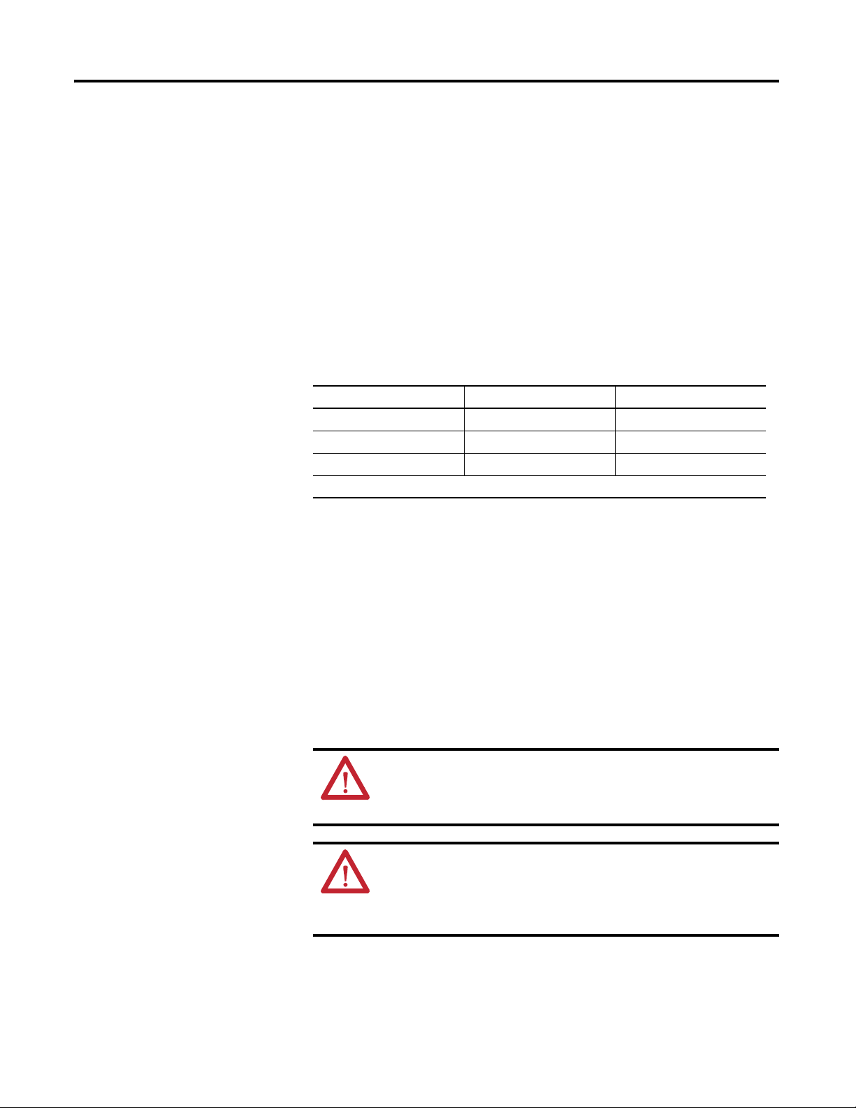
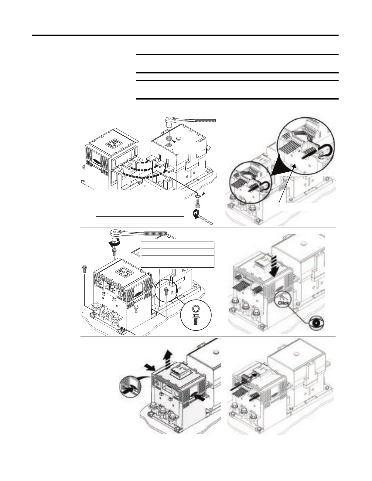
Installation
The 100-C09…C43 Starter Assembly installation instructions for use with
Catalog Numbers 193-EC_ _B and -EC_ _D are shown in Figure 2
.
18 Rockwell Automation Publication 193-UM002I-EN-P - December 2011
Page 19
Installation & Wiring Chapter 2
3
1
2
2.5 N m
2 lb in
2
4 N·m
35 lb-in
1
Figure 2 - 100-C09…C43 Starter Assembly Installation
The 100-C60…C85 Starter Assembly installation instructions for use with
Catalog Numbers 193-EC_ _E are shown in Figure 3
.
Figure 3 - 100-C60…C85 Starter Assembly Installation
The 100-D95…D860 Starter Assembly installation instructions for use with
Catalog Numbers 193-EC_ _F, 193-EC_ _G, and -EC_ _H are shown below.
ATTENTION: The voltage ratings of the E3 Overload Relay’s output and
trip relays must not be exceeded. If the voltage ratings are exceeded, an
interposing relay must be used.
ATTENTION: Connect the internal metal shield to a solid earth ground
via a low impedance connection.
Rockwell Automation Publication 193-UM002I-EN-P - December 2011 19
Page 20
Chapter 2 Installation & Wiring
IMPORTANT
IMPORTANT
1
100-D95 / D110
100-D95E / D110E / D115E
100-D115 / D140 / D180
100-D210 / D420
100-D630 / D860
Ground fault protection requires connection of an external core balance
current transformer (CBCT).
For identification of the proper CT ratio to be programmed, refer to the
product nameplate.
Figure 4 - 100-D95…D860 Starter Assembly Installation
4
Supplied
with Contactor
1
Supplied
11 N·m (100 lb-in)
22 N·m (195 lb-in)
43 N·m (380 lb-in)
68 N·m (600 lb-in)
with
Contactor
Accessory 193-EIMD shown.
2
193-EC _ _ F
193-EC _ _ G
193-EC _ _ H
(M5) 3.4 N·m (30 lb-in)
(M6) 7.3 N·m (65 lb-in)
(M12 Provided)
45 N·m (400 lb-in)
3
a
b
5
6
a
20 Rockwell Automation Publication 193-UM002I-EN-P - December 2011
Page 21
Installation & Wiring Chapter 2
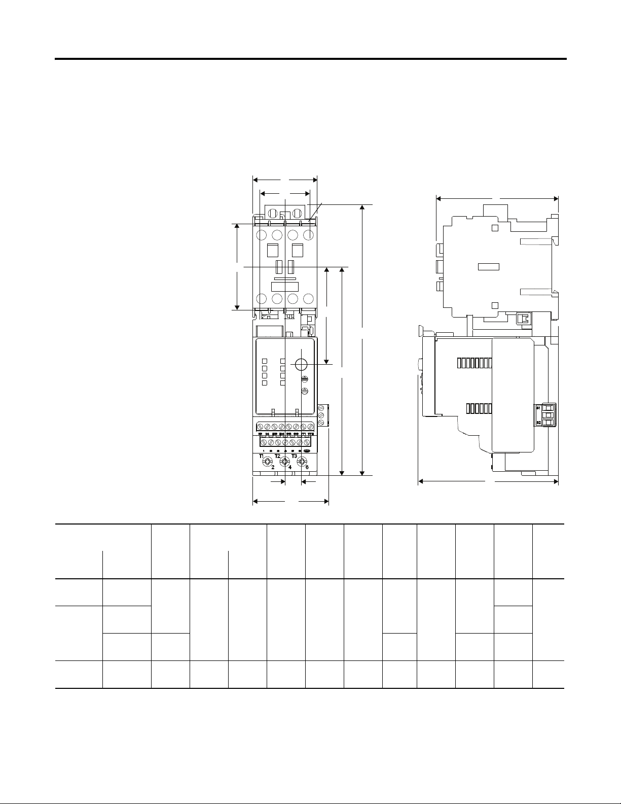
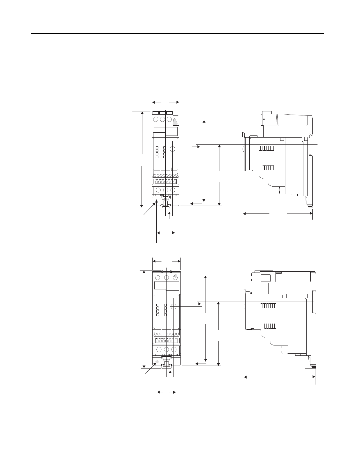
Approximate Dimensions
Approximate dimensions are shown in millimeters (inches). Dimensions are not
intended to be used for manufacturing purposes.
Figure 5 - Overload Relay 193-EC_ _ B, D, & E with Contactor 100-C*
A
D1
D2
ØD
E1
B
H
B1
11.4
(29/64)
F1
Height B
Cat. No.
Overload
Relay
193-EC_ _B C09, C-12,
193-EC_ _D C30, C37 104
193-EC_ _E C60, C72,
Contactor
100-
C16, C2345(1-25/32)
C43 54
C85
Width
A without with B1
(2-1/8)
72
(2-53/64)
193-EIMD
188.3
(7-13/32)
236.1
(9-19/64)
207.7
(8-11/64)
255.5
(10-1/16)
145.1
(5-23/32)
173.2
(6-13/16)
Depth
C E1F1D1D2H Ø D
107
(4-7/32)
124.6
(4-29/32)
67.9
(2-43/64)
89.8
(3-17/32)
53.2
2-3/32)60(2-23/64)35(1-3/8)
62.2
(2-7/16)
80.2
(3-9/64)
100
(3-15/16)55(2-11/64)
45
(1-25/32)
C
85.1
(3-23/64)
(4-3/32)
107
(4-7/32)
125.5
(4-15/16)
4.2
(11/64)
5.5
(7/32)
Rockwell Automation Publication 193-UM002I-EN-P - December 2011 21
Page 22
Chapter 2 Installation & Wiring
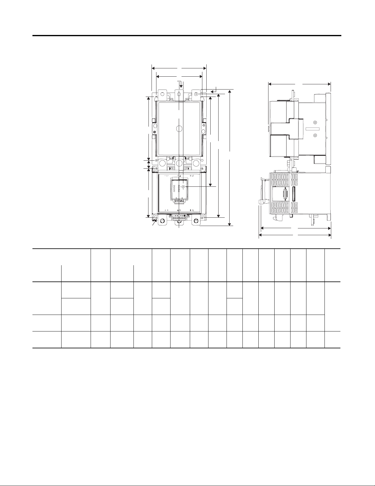
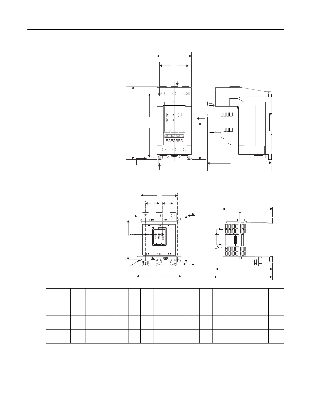
Figure 6 - Overload Relay 193-E_ _F, G, & H with Contactor 100-D*
A
G
11.4
(0.45)
C
L
H
K
J
F
E1
B1
B
D
Cat. No.
Overload
Relay
193-EC_ _F D95, D110 120
193-EC_ _G D210, D250,
193-EC_ _H D630, D860 255
Contactor
100-
D140, D180 339.8
D300, D420
Width
A without with B1
(4.72)
155
(6.10)
(10.04)
Height B
193-EIMD
336.3
(13.24)
(13.38)
385.8
(15.19)
552
(21.73)
418
(16.46)
487.4
(19.19)
915
(36.02)
ØM
311.8
(12.27)
317.8
(12.51)
360.8
(14.2)
508
(20.0)
C
L
Depth
C D E1F GHJ KL ØM
175.1
(6.89)
198.9
(7.83)
291.7
(11.49)
156
(6.14)
180
(7.09)
270.7
(10.66)
216.1
12.5
(8.51)
(0.49)
16
(0.63)
255
(10.04)21(0.83)
373.9
(14.72)
52.5
(2.07)
100
(3.94)
130
(5.12)
226
(8.90)
145
(5.71)
180
(7.09)
230
(8.90)
135
(5.31)
140
(5.51)
108
(4.25)
22.3
(0.88)
23.5
(0.93)
109
(4.29)
180.9
5.6
(7.12)
(0.22)
204.7
(8.06)
297.5
(11.71)13(0.51)
22 Rockwell Automation Publication 193-UM002I-EN-P - December 2011
Page 23
Installation & Wiring Chapter 2
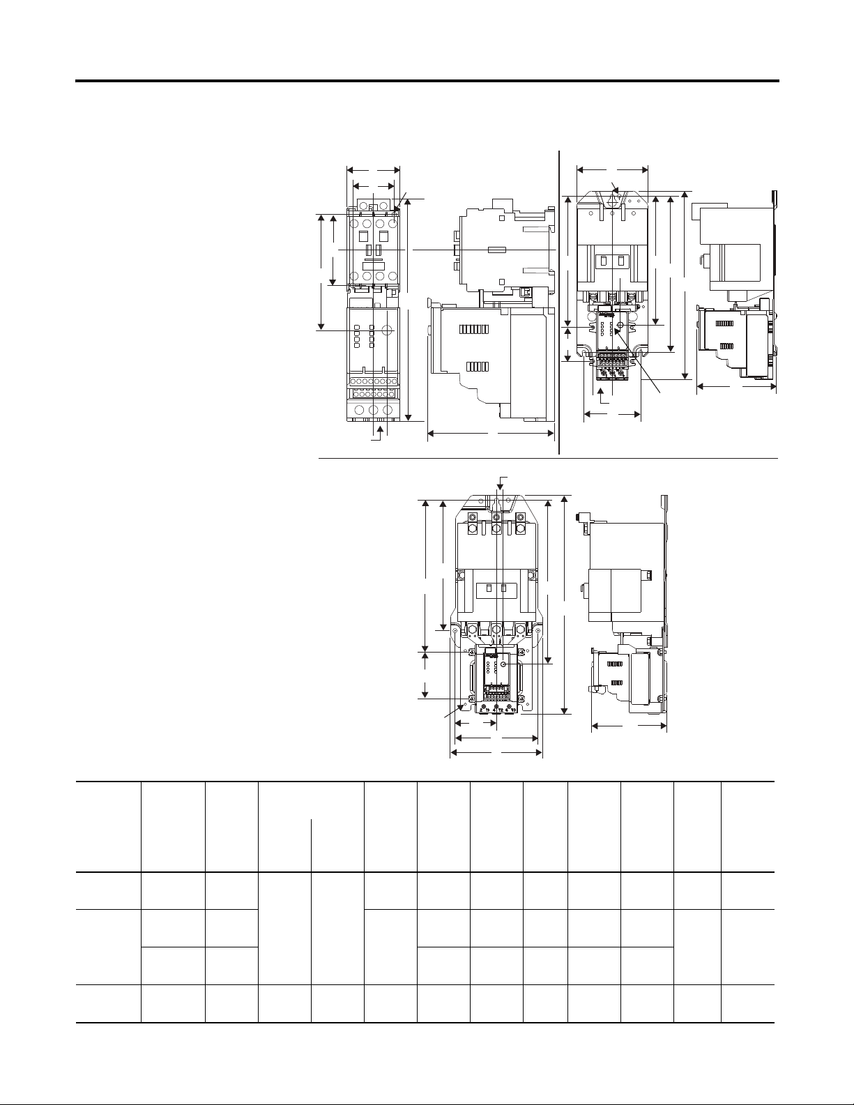
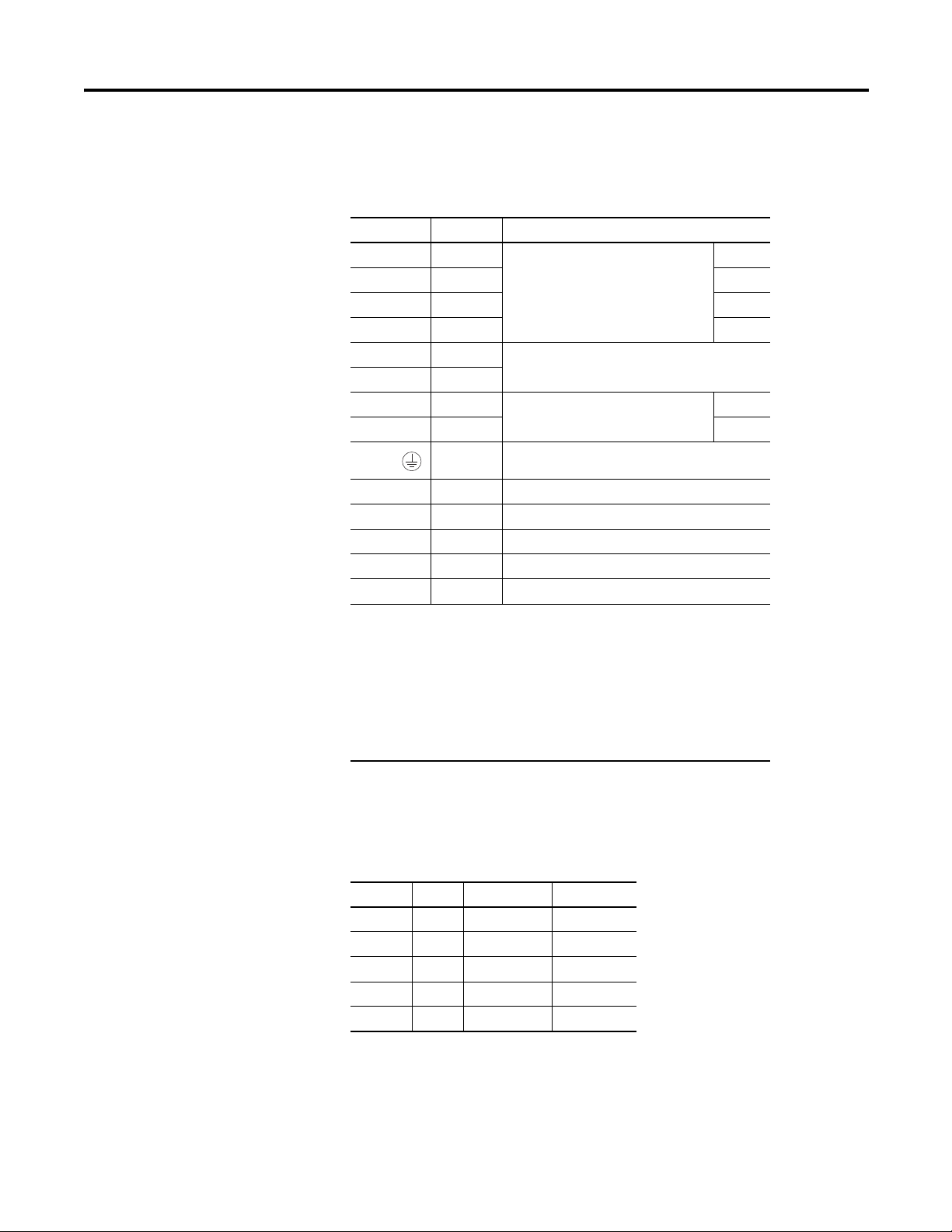
Figure 7 - Overload Relay 592-EC_ _ T, C, & D with NEMA Contactor
Size 00
A
D
ØF
Size 0...2
A
ØF
H
E
(29/64)
11.4
B
Size 3
J
J
K
L
D
C
11.4
(29/64)
E
H
B
H
11.4
(29/64)
E
B
C
Cat. No.
Overload
Relay
592-EC_ _T 00 45
592-EC_ _C 0, 1 90.4
592-EC_ _D 3 155.5
NEMA
Contactor
Size
2100
Width
A without with
(1-25/32)
(3-9/16)
(3-15/16)
(6-1/8)
K
ØF
Height B
193-EIMD
Depth
CDEØFHJKL
188.3
(7-13/32)
236.1
(9-19/64)
Rockwell Automation Publication 193-UM002I-EN-P - December 2011 23
207.7
(8-11/64)
255
(10-1/16)
107
(4-7/32)35(1-3/8)60(2-23/64)
112.1
(4-13/32)
126.3
(4-31/32)
69.9
(2-3/4)
80
(3-5/32)
139.9
(5-33/64)
L
D
A
179.4
(7-1/16)
219.3
(8-5/8)
219.9
(8-43/64)
4.2
(11/64)
5.15
((13.64)
5.54
(7/32)
7.1
(9/32)
97.9
(3-27/32)
159.4
(7-15/32)
186
(7-21/64)
276.7
(10.9)
C
———
163
(6-7/16)
189.5
(7-15/32)
256.3
(10-3/32)
47.5
(1-7/8)
78.5
(3-3/32)
27.5
(1-5/64)
42.3
(1-21/32)
Page 24
Chapter 2 Installation & Wiring
11.4
(29/64)
30
(1-3/16)
45
(1-25/32)
7.3
(9-32)
135
(5-5/16)
154.2
(6-5/64)
100.5
(3-31/32)
6.1
(1/4)
115
(4-17/32)
Ø 4.4
(11/64)
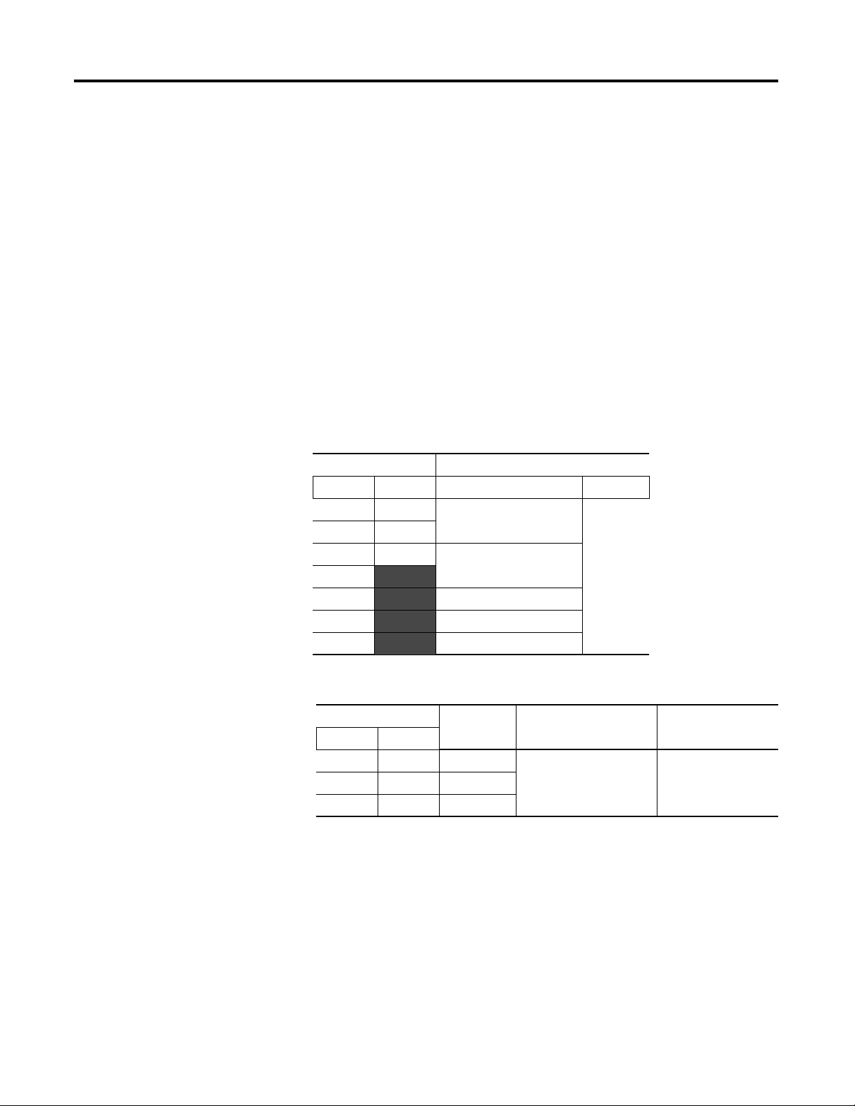
Separate Panel Adapter
Approximate Dimensions
Approximate dimensions are shown in millimeters (inches). Dimensions are not
intended to be used for manufacturing purposes.
Figure 8 - 193-ECPM1 Panel Adapter for use with Cat. No. 193-EC_ _B
45
(1-25/32)
7.3
(9/32)
159.3
(6-17/64)
Ø 4.4
(11/64)
11.4
(29/64)
30
(1-3/16)
135
(5-5/16)
6.1
(1/4)
100.5
(3-31/32)
115
(4-17/32)
Figure 9 - 193-ECPM2 Panel Adapter for use with Cat. No. 193-EC_ _D & Z
24 Rockwell Automation Publication 193-UM002I-EN-P - December 2011
Page 25
Installation & Wiring Chapter 2
K
0
2
4
6
8
0
2
4
6
8
M
N
P
A
D
B
C
E
F
E
L
J
G
I
H
Figure 10 - 193-ECPM3 Panel Adapter for use with Cat. No. 193-EC_ _E
71.7
(2-53/64)
60
(2-23/64)
11.4
(29/64)
150.5
(5-15/16)
155.1
(6-7/64) w/
130
(5-1/8)
(19/32)
193-EIMD
77
(3-1/32)
131.2
15
5.0
(13/64)
Ø 5.5
(7/32)
(5-11/64)
Figure 11 - Separate Panel Adapter for use with Cat. No. 193-EC_ _ F, G, & H
Overload
Cat. No.ABCDEFGHI JKLMNP
193-EC_ _ F 4.72
(120.0)
193-EC_ _ G 6.09
(154.7)
193-EC_ _H 10.0
(255.0)
7.19
(182.6)
7.40
(188.1)
10.28
(261.0)
6.09
(154.6)
6.41
(162.8)
8.54
(217.0)
3.94
(100)
5.12
(130)
8.90
(226)
1.54
(39)
1.89
(48)
2.76
(70)
0.45
(11.4)
0.45
(11.4)
0.45
(11.4)
1.03
(26.3)
1.06
(26.8)
3.97
(100.8)
5.32
(135)
5.51
(140.0)
4.24
(107.7)
1.94
(49.4)
2.03
(51.5)
1.37
(134.9)
0.22
(5.6)
0.26
(6.5)
0.53
(13.5)
0.24
0.47
(6.0)
(12)
0.08
0.49
(2.0)
(12.5)
—0.87
(22.0)
5.95
(151.2)
6.89
(175)
10.54
(267.8)
6.89
(175)
7.83
(198.9)
11.49
(291.7)
7.12
(180.9)
8.06
(204.7)
11.72
(297.5)
Rockwell Automation Publication 193-UM002I-EN-P - December 2011 25
Page 26

Chapter 2 Installation & Wiring
Voltage Input Module
The voltage input module, Cat. No. 193-NVEC5VIM, is an add-on accessory for
use with the E3 Plus. Approximate dimensions are shown in millimeters (inches).
Dimensions are not intended to be used for manufacturing purposes.
Figure 12 - 193-NVEC5VIM Voltage Input Module
0.886
(22.5)
L1
L2
L3
0.457
(11.6)
2.972
(75.5)
2.782
(70.65)
Ø 0.177
(4.5)
Specifications
3.216
(82.0)
Power Terminals
Table 2 - Wire Size & Torque Specification
193-EC_ _B & D,
Wire Type Conductor Torque
Stranded/Solid [AWG] Single #14…6 AWG
Multiple #10…6 AWG
Flexible-Stranded with Ferrule Metric Single 2.5…16 mm
Multiple 6…10 mm
Coarse-Stranded/Solid Metric Single 2.5…25 mm
Multiple 6…16 mm
592-EC_ _T, C
22 lb-in.
30 lb-in.
2.5 Nm
3.4 Nm
2.5 Nm
3.4 Nm
Cat. No.
2
2
2
2
193-EC_ _E,
592-EC_ _D
#12…1 AWG
35 lb-in.
#6…2 AWG
35 lb-in.
4…35 mm
4 Nm
4…25 mm
4 Nm
4…50 mm
4 Nm
4…35 mm
4 Nm
2
2
2
2
26 Rockwell Automation Publication 193-UM002I-EN-P - December 2011
Page 27

Three-Pole Terminal Blocks
Table 3 - Three-Pole Terminal Blocks
Installation & Wiring Chapter 2
Cat. No. 100-DTB1890 (A) 6…1/0 AWG, 16…50 mm
(B) 6 AWG…250 MCM, 16…120 mm
90…110 lb.-in., 10…12 Nm
100-DTB420 (2) 4 AWG…600 MCM, 25…240 mm
180…220 lb.-in., 20…25 Nm
2
Terminal Lug Kits
Table 4 - Terminal Lug Kits
Cat. No. 100-DL 110 Lug 6…2/0 AWG, 16…70 mm
90…110 lb.-in., 10…12 Nm
Terminal 13/32 in, 10 mm
150 lb.-in., 17 Nm
180 Lug 6 AWG…250 MCM, 16…120 mm
90…110 lb.-in., 10…12 Nm
Terminal 1/2 in., 13 mm
275 lb.-in., 16 Nm
420 Lug 2 AWG…350 MCM
375 lb.-in., 42 Nm
Terminal 11/16 in., 17 mm
140 lb.-in., 16 Nm
630 Lug 2/0 AWG…500 MCM, 70…240 mm
400 lb.-in., 45 N
Terminal 3/4 in, 19 mm
600 lb.-in., 68 Nm
860 Lug 2/0 AWG…500 MCM, 70…240 mm
400 lb.-in., 45 Nm
Terminal 3/4 in, 19 mm
600 lb.-in., 68 Nm
2
2
2
2
2
2
Control, DeviceNet, & Voltage Input Module Terminals
Table 5 - Wire Size & Torque Specification
Wire Type Conductor Torque All Cat. No. Types
Stranded/Solid [AWG] Single 24...12 AWG
Multiple
(stranded only)
Rockwell Automation Publication 193-UM002I-EN-P - December 2011 27
24...16 AWG
5 lb-in
Page 28

Chapter 2 Installation & Wiring
Wire Type Conductor Torque All Cat. No. Types
Flexible-Stranded with Ferrule Metric Single 0.25…2.5 mm
Multiple 0.5...0.75 mm
2
2
0.55 Nm
Coarse-Stranded/Solid Metric Single 0.2...2.5 mm
Multiple 0.2...1.5 mm
2
2
0.55 Nm
Table 6 - Maximum Wire Length (PTC & input)
Minimum Cross Section mm
2
0.5 0.75 1.5 2.5 4.0
AWG 20 18 16 14 12
Maximum Length ➊ meters 160 250 400 600 1000
feet 525 825 1300 1950 3200
➊ The use of shielded cable is recommended for the PTC thermistor circuit to assist in
obtaining compliance with Electromagnetic Compatibility (EMC) requirements.
Shielded cable is recommended for the input circuits, where wire lengths exceed 200
meters (656 feet).
NOTE: For reliable input signal processing, input wiring should be routed in raceways
separate from power cabling.
Table 7 - Ground Fault Sensor Terminals (S1 & S2)
Wire Type Shielded, Twisted Pair
Cross Section 0.2…4.0 mm
Torque 0.55 N·m (5 lb.-in.)
2
(#24…12 AWG)
28 Rockwell Automation Publication 193-UM002I-EN-P - December 2011
Page 29
Installation & Wiring Chapter 2
Terminal Designations
Control Terminals
Table 8 - Control Terminal Designation
Terminal Reference Description
1IN 1
2IN2 2
3IN 3 3
4IN 4 4 ➊➋
5V+ +24V
6V+
7IN 5
8IN 6 6 ➋
END Earth Ground ➌
13/14 OUT A Output A
23/24 OUT B Output B ➊➋
95/96 Trip Relay Trip Relay
IT1/IT2 PTC Thermistor (PTC) Input ➊➍
S1/S2 — External Ground Fault Sensor Input ➋➎
General Purpose Sinking Input Number:
General Purpose Sinking Input Number:
1
➊➋
5 ➋
➊
Features are available only with the E3 Plus Overload Relay (Cat. No. 193/592-EC2 and
193/592-EC3).
➋ Available only on Cat. Nos. 193/592-EC5_ _.
➌ An earth ground connection to this terminal will assist in obtaining compliance with
EMC requirements.
➍ The use of shielded cable is recommended for the positive PTC thermistor circuit to
assist in obtaining compliance with EMC requirements.
➎ Available only on Cat. No. 193/592-EC3_ _ and 193/592-EC4_ _.
DeviceNet Terminals
Table 9 - DeviceNet Terminal Designation
Terminal Signal Function Color
1 V- Common Black
2 CAN_L Signal Low Blue
3 Drain Shield Non-Insulated
4 CAN_H Signal High White
5 V+ Po9wer Supply Red
Grounding
The following grounding recommendations are provided to ensure EMC
requirements during installation.
Rockwell Automation Publication 193-UM002I-EN-P - December 2011 29
Page 30
Chapter 2 Installation & Wiring
• The earth ground terminal of the E3 Overload Relay shall be connected to
a solid earth ground via a low-impedance connection.
• Installations employing an external ground fault sensor shall ground the
cable shield at the sensor with no connection made at the E3 Plus Overload
Relay.
• The PTC thermistor cable shield shall be grounded at the E3 Plus
Overload Relay with no connection made at the opposite end.
Short-Circuit Ratings
The E3 Overload Relay is suitable for use on circuits capable of delivering not
more than the RMS symmetrical amperes listed in the following tables.
Short-Circuit Ratings
Table 10 - UL
Cat. No. Maximum
193-EC_ _ 592-EC_ _ Available Fault Current [A] Voltage [V]
B T 5,000 600
DC
ED10,000
F
G 18,000
H 42,000
Z 5,000
Table 11 - IEC
Cat. No.
B T 1,000 100,000 690
D C 3,000
E D 5,000
Prospective
Current I
r
[A]
Conditional Short-Circuit
Current Iq [A]193-EC_ _ 592-EC_ _ Maximum Voltage [V]
30 Rockwell Automation Publication 193-UM002I-EN-P - December 2011
Page 31

Installation & Wiring Chapter 2
High-Fault Short-Circuit Ratings
Table 12 - Per UL 508 & CSA 22.2, No. 14 with Bulletin 100-C & 100-D Contactors
Cat. No.
193-EC1, -EC2, -EC3,
-EC4, -EC5
_B C09 9 100,000 600 20
_D C30 30 100,000 600 50
_E C60 60 100,000 600 80
FF, ZZ D95 95 100,000 600 200
GF, ZZ D180 180 100,000 600 300
GG, ZZ D210 210 100,000 600 400
HG, ZZ D210 210 100,000 600 400
JG, ZZ D300 300 100,000 600 500
Contactor
100-
C12 12 20
C16 16 30
C23 23 30
C37 37 50
C43 43 70
C72 72 100
C85 85 150
D110 110 200
D140 140 250
D250 250 400
D300 300 500
D250 250 400
D300 300 500
D420 420 600
Starter
FLC [A]
Available Fault
Current [A] Voltage [V]
Maximum
Class J or
CC Fuse [A]
Rockwell Automation Publication 193-UM002I-EN-P - December 2011 31
Page 32

Chapter 2 Installation & Wiring
Table 13 - Per UL 508 & CSA 22.2, No. 14 with NEMA Contactors
Maximum
Cat. No.
592-EC1, -EC2,
-EC3, -EC5
_T 00 100,000 600 — 20 —
_C 0 100,000 240 30 30 FDB 3025/
_D 3 100,000 240 200 350 FDB 3150/
Contactor
Size
1 100,000 240 60 100 FDB 3050/
2 100,000 240 100 200 FDB 3100/
Available Fault
Current [A]
Voltage
[V]
480 30 30 FDB 3025/
600 30 30 —
480 30 50 FDB 3050/
600 30 50 —
480 60 100 —
600 60 100 —
480 100 200 FDB 3125/
600 100 200 FDB 3100/
UL Fuse [A]
RJ
Circuit Breaker/
Limiter
LFB3070R
LFB3070R
LFB3035R
LFB3035R
LFB3150R
LFB3150R
LFB3150R
LFB3150R
Fuse Coordination
The following tables list Type I and Type II Fuse Coordination when used in
conjunction with Bulletin 100-C and 100-D Contactors.
ATTENTION: Select the motor branch circuit protection that complies
with the NEC and any other governing regional or local codes.
32 Rockwell Automation Publication 193-UM002I-EN-P - December 2011
Page 33

Table 14 - IEC per EN60947-4-1
Installation & Wiring Chapter 2
Cat. No. 193EC1, EC2,
EC3, EC4, EC5
Contactor
100-
Max.
Starter
FLC [A]
Short-Circuit Current
Prospective
[A]
I
r
Conditional
Iq [A]
Max.
Voltage
[V]
Class J Fuse [A]
with
Type I
with
Type II
_B C09 9 1,000 100,000 600 20 15
C12 12 20 20
C16 16 30 30
C23 23 40 40
_D C30 30 3,000 100,000 600 50 50
C37 37 50 50
C43 43 70 70
_E C60 60 3,000 100,000 600 80 80
C72 72 100 100
C85 85 5,000 150 150
FF, ZZ D95 95 10,000 100,000 600 200 200
D110 110 200 200
D140 140 250 250
GF, ZZ D180 180 10,000 100,000 600 300 300
GG, ZZ D210 210 10,000 100,000 600 400 400
D250 250 400 400
D300 300 500 500
HG, ZZ D210 210 10,000 100,000 600 400 400
D250 250 400 400
D300 300 500 500
JG, ZZ D300 300 10,000 100,000 600 500 500
D420 420 600 600
Table 15 - NEMA Contactors
Short-Circuit Current
Prospective
[A]
I
r
Conditional
Iq [A]
Max.
Voltage
[V]
Cat. No.
592-EC
Contactor
Size
Max.
Starter
FLC [A]
_T 00 9 1,000 100,000 600 20 20
_C 0, 1 18, 27 3,000 30 30
245 6060
_D 3 90 5,000 200 200
Rockwell Automation Publication 193-UM002I-EN-P - December 2011 33
Class J Fuse [A]
with
with
Type I
Type II
Page 34

Chapter 2 Installation & Wiring
IMPORTANT
IMPORTANT
L1
2/T1
4/T2
6/T3
M
T1
Three-Phase Direct-On-Line
Single-Phase Full-Voltage
T2
L2
E3/E3 Plus
L1 L2
Voltage Input Module
(For 193/592-EC5 only)
E3/E3Plus
L1
2/T1
4/T2
6/T3
M
T1T2T3
S.C.P.D.
L2
L3
L1
L2
L3
Voltage Input Module
(For 193/592-EC5 only)
S.C.P.D.
Typical Motor Connections
Three-Phase Direct On-Line (DOL) & Single-Phase Full Voltage
ATTENTION: When working on energized circuits, DO NOT rely on
voltage and current information provided by the E3 and E3 Plus Overload
Relay for personal safety. Always use a portable voltage or current
measurement device to measure the signal locally.
Single/Three Ph, Parameter 27, should be set to single-phase.
Traditional single-phase wiring connecting T2 to L3 will result in a vector
imbalance of current flowing through the E3 Plus Overload Relay. This
will result in inaccurate ground fault reporting and protection.
The following wiring diagram illustrates the E3 Overload Relay typical motor
connections in a three-phase DOL and Single-Phase Full Voltage applications.
Figure 13 - Wiring Diagram, Three-Phase DOL & Single-Phase Full Voltage
External Line Current Transformer Application
34 Rockwell Automation Publication 193-UM002I-EN-P - December 2011
193-EC_ZZ E3 and E3 Plus Overload Relays are designed for use with separately
mounted, customer-supplied, line current transformers (CTs) as required in
higher-current applications. The FLA setting range is 9…5000 A for these units
with a legal setting range per current transformer. CT Ratio, Parameter 78, is
provided for setting the current transformer ratio to be installed.
Specifications
The 193-EC_ZZ Overload Relays are intended for use with CTs having a
secondary current rating of 5 A. The installer shall (1) provide one CT for each
motor phase and shall (2) connect the CT’s secondary leads to the appropriate E3
Page 35

Installation & Wiring Chapter 2
Overload Relay power terminals as shown in Figure 14 on page 36. The CTs shall
have an appropriate ratio rating as detailed in Table 18.
Additionally, the CT shall be selected to be capable of providing the required VA
to the secondary load, which includes the E3 Overload Relay burden of 0.1 VA at
the rated secondary current and the wiring burden.
Finally, the CT shall (1) be rated for Protective Relaying to accommodate the
high inrush currents associated with motor startup and shall (2) have an accuracy
≤±2% over its normal operating range. Typical CT ratings include:
of
• ANSI USA
• CSA (Canada)
• IEC (Europe)
ATTENTION: The improper selection of a current transformer can result
in the E3 Overload Relay reporting inaccurate motor operational data and
possible motor damage. The selected current transformer must be rated
for protective relaying applications.
• Class C5 BO.1
• Class 10L5
• 5 VA Class SP10
Installation Requirements
• The 193-EC_ZZ Overload Relays are designed to be installed in193ECPM2 Panel Mount Adapters and connected to separately mounted
current transformers.
• For 193-ECPM2 Panel Mount Adapter assembly, refer to the instructions
included with the panel mount adapter.
ATTENTION: Placing the E3 Overload Relay closer than the
recommended distance, six times the cable diameter (including
insulation), may compromise its current reporting and protection
capabilities.
• The E3 Overload Relay must be mounted a distance equal to or greater
than six times the cable diameter (including insulation) from the nearest
current-carrying conductor or current transformer.
• For applications employing multiple conductors per phase, the diameter of
each cable should be added and multiplied by six to determine the proper
placement distance for the E3 Overload Relay.
Rockwell Automation Publication 193-UM002I-EN-P - December 2011 35
Page 36

Chapter 2 Installation & Wiring
Primary
Current
Transformers
E3 Overload
Relay
6x
6x
or
NEMA
L1 L2
L3
L1/1 L2/3 L3/5
T1/2 T2/4 T3/6
E3
M
T1
T2
T3
IEC
L1 L2
L3
K1
L1/1 L2/3 L3/5
T1/2 T2/4 T3/6
E3
M
Primary
Current
Transformers
Primary
Current
Transformers
Figure 14 - Overload Relay Mounting Placement
Figure 15 - External CT Connection Diagrams
External Potential Transformer (PT) Connection
The 193/592-EC5_ _ E3 Plus Overload Relay can be used with external stepdown PTs. The PT ratio is programmed into the E3 Plus Overload Relay by
entering the primary winding rating into PT Pri, Parameter 289, and the
secondary winding rating into PT Sec, Parameter 290. The voltage mode is also
programmed into the E3 Plus Overload Relay by selecting the appropriate mode
in Volt Mode, Parameter 156. The E3 Overload Relay Plus will support Wye,
Delta, and Open Delta voltage modes with potential transformers.
36 Rockwell Automation Publication 193-UM002I-EN-P - December 2011
Page 37

Table 16 - Wiring Diagrams, External PT Connection
Load
Wye Connection with PTs
Delta Connection with PTs
Line
L1 L2 L3
N/GRND
L1 L2 L3
Line
L1 L2 L3
L1 L2 L3
Load
Open Delta Connection with PTs
Line
L1 L2 L3
Load
L1 L2 L3
Installation & Wiring Chapter 2
Core Balanced Ground Fault Sensor Application
The 193-EC3_ _ E3 Plus Overload Relays are intended to provide ground fault
protection when used with the external 193-CBCT_ Core Balanced Ground
Fault Sensor. The ground fault sensor mounts separately from the E3 Plus
Overload Relay and must be placed within three meters of the E3 Plus Overload
Relay. The customer-supplied power cable for wiring the ground fault sensor to
the E3 Plus Overload Relay must meet the specifications outlined in Ta bl e 7 o n
page 28.
Power Cable Installation Requirements
• All power cables (including the neutral when used) must pass through the
sensor window. The equipment ground conductor (the conductor used to
carry the non-current-carrying metal parts of equipment, as defined by
Article 100 of the NEC) must not pass through the sensor window.
• The power cables through the sensor window should be straight, tightly
bundled, centered in the window, and perpendicular to the sensor for a
length equal to or greater than six times the cable diameter (including
insulation) from the sensor.
• All other conductors with available fault currents in excess of 1,000 A
should be placed a distance equal to or greater than six times the cable
diameter (including insulation) from the sensor.
• The power cables of the branch circuit to be protected by the E3 Plus
Overload Relay must not be grounded on the load side of the ground fault
sensor.
Rockwell Automation Publication 193-UM002I-EN-P - December 2011 37
Page 38

Chapter 2 Installation & Wiring
L3
L1
L2
L1
L2
L3
1
1
The spacer is a short piece of cable, approximately
ten times the cable diameter in length, without
connections to any terminal.
• If the power cables are enclosed in a conducting jacket, the jacket must be
grounded on the line side of the sensor. The jacket must not pass through
the sensor window, but must be cut at the window and joined with a
conductor that passes outside the sensor window.
• The power system may be solidly grounded or grounded through an
impedance at its source as long as the impedance allows a magnitude of
current to flow that is within the 20 mA…5 A operational range of the E3
Plus Overload Relay.
Figure 16 - Core Balanced Ground Fault Sensor Mounting Placement
90°
6x
Fault Sensor
Core Balanced Ground
Power
Cables
6x
Figure 17 - Power Cable Configuration — Two Cables per Phase
Figure 18 - Ground Fault Sensor Wiring
E3 Plus Overload Relay
L1 L2
1
L3
35
L1 L2 L3
Cat. No. 193-CBCT_
Core Balanced
Ground Fault Sensor
S1
S2
13 14 23 24 95 96 1T1 1T2
1 2 3 4 5 6
T1
T2
T3
2
4
6
Motor
38 Rockwell Automation Publication 193-UM002I-EN-P - December 2011
Page 39

Installation & Wiring Chapter 2
IMPORTANT
Control Wire Requirements
The shield of the twisted pair cable must be connected to earth ground
at the ground fault sensor with no connection made at the E3 Plus
Overload Relay.
• The maximum length of the shielded cable is 100 feet (30.48 meters).
• All control terminals are for copper wire only in sizes #12…24 AWG.
• Ring lug termination is required for the ground sensor terminals of 193-
CBCT2 and larger.
• The sensor fastener torque is 26…30 lb-in.
• The 193-CBCT1 wires should be twisted before termination by applying
one twist per inch (per 25.4 millimeters).
Table 17 - Control Wire Specifications
Cat. No.
193-
CBCT1 45 50/60 1000:1 19.1 mm
CBCT2 90 #2 AWG
CBCT3 180 #250 MCM
CBCT4 420 $350 MCM
➊ For a three-phase system with one cable per phase.
➋ For a three-phase system with two cables per phase.
Max.
Current
[A] Hz
Tur ns
Ratio
Sensor
Window
I.D.
(.75 in.)
Max.
Recommended
Cable Size @ 600V
#8 AWG
(10 mm2) ➊
(350 mm
(120 mm
(185 mm
Approximate Dimensions
2
2
2
) ➊
) ➊
) ➋
Cat. No.
100-C09 IEC
Contactor
…-C37 00…2
…-C85 00…3
…-D180 00…4
…-D240 00…5
NEMA
Contactor
Size
Approximate dimensions are shown in millimeters (inches). Dimensions are not
intended to be used for manufacturing purposes.
Rockwell Automation Publication 193-UM002I-EN-P - December 2011 39
Page 40

Chapter 2 Installation & Wiring
Figure 19 - 193-CBCT1
12.7
(.50)
50.8
63.5
(2.00)
(2.50)
45.3
(1.78)
23.1
(.91)
Ø 44.5
(1.75)
Ø 19.1
(.75)
3.2
(.12)
4.0
(.16)
Figure 20 - 193-CBCT2 & 193-CBCT3
E
44.5
(1.75)
5.3
(.21)
F
11.8
(.47)
B
Cat. No.ABC ØDE F
193-CBCT2 96
(3.78)
193-CBCT3 122.4
(4.82)
89.6
(3.53)
115.9
(4.56)
48.3
(1.90)
59.7
(2.35)
A
C
39.6
(1.56)
63.5
(2.50)
3.2
(.13)
Ø D
54.6
(2.15)
54.1
(2.13)
69.9
(2.75)
98.0
(3.78)
Figure 21 - 193-CBCT4
146.8
74.4
(2.93)
56.2
(2.21)
11.8
(.47)
82.6
(3.25)
(5.78)
74.9
(2.95)
3.2
(.13)
5.5
(.22)
96.7
123.2
(4.85)
(3.81)
143.5
(5.65)
40 Rockwell Automation Publication 193-UM002I-EN-P - December 2011
Page 41

Typical Control Circuit Wiring Diagrams
ATTENTION: Do not exceed the ratings of the E3 Overload Relay’s
output and trip relay. If the coil current or voltage of the contactor exceeds
the overload relay’s ratings, an interposing relay must be used.
ATTENTION: When the power is applied to the E3 Overload Relay,
DeviceNet terminals V+ and V-, the N.O. trip relay contact across
terminals 95 and 96 will close after approximately 2.35 seconds if no trip
condition exists.
ATTENTION: Additional control circuit protection may be required. Refer
to the applicable electrical codes.
ATTENTION: Do not apply external voltage to 1T1, 1T2, or the input
terminals IN 1…4. This may cause equipment damage.
Installation & Wiring Chapter 2
Full-Voltage Non-Reversing Starter (with Network Control)
Figure 22 - NEMA Nomenclature
L2
6/T3
Three-Phase
SPCD
L1
E3/E3 Plus
4/T2
2/T1
T2
T1
L2 L3
T3
M
6/T3
13
E3
Out A
A1
14
Single-Phase
SPCD
L1
E3/E3 Plus
4/T2
2/T1
T2
T1
M
1
Contact shown with supply voltage applied.
E3
1
Trip Relay
A2
M
96
95
Rockwell Automation Publication 193-UM002I-EN-P - December 2011 41
Page 42

Chapter 2 Installation & Wiring
L1
E3 Plus
Trip Relay
2
95
96
13
23
E3 Plus
Out B
14
24
K2
K1
A1 A1
K1
K2
A2
A2
N
Contact shown with supply voltage applied.
2
E3 Plus
Out A
Figure 23 - CENELEC Nomenclature
Single-Phase
Three-Phase
L1
1 3 5
A1
K1
A2
2 4 6
T1 T3 T5
M
2
Contact shown with supply voltage applied.
A1
K1
A2
1 3 5
2 4 6
T1 T3 T5
M
Full-Voltage Reversing Starter (with Network Control)
Figure 24 - NEMA Nomenclature
E3 Plus
Out A REV
13 14
E3 Plus
Out B FOR
23 24
A1 A2
FOR
A1 A2
REV
E3 Plus
Trip Relay
95 96
1
Contact shown with supply voltage applied.
Out A
E3
Trip Relay
N
1
E3
13
14
95
2
96
A1
K
A2
Figure 25 - CENELEC Nomenclature
42 Rockwell Automation Publication 193-UM002I-EN-P - December 2011
Page 43

Installation & Wiring Chapter 2
E3 Plus
Out A
E3 Plus
Out B
13 14
23 24
LOW
HIGH
A1 A2
A1 A2
95 96
E3 Plus
Trip Relay
1
Contact shown with supply voltage applied.
1
LOW
HIGH
Figure 26 - IEC Reversing Starter Application Schematic
24V -
CAN L
Shield
CAN H
24V +
24V
red
CAN H
white
13 14
13 14
5
3
1
K2M
K2M
K1M
shield
blue
black
6
4
2
CAN L
24V -
OUT B
23 24 22 21
OUT A
13 14 22 21
96
95
6
24V +
5
IN4
IN3
IN2
IN1
1T2
1T1
K1M
K2M
6
4
2
W
V
U
F2
A1 A2
K2M
A1 A2
K1M
M
3~
N
230V AC
DeviceNet
23 24
Q1
13 14
Q1
6
5
5
L3
4
L2
L1
3
2
1
Q1
6
3
4
1
2
K1M
Two-Speed Non-Reversing (with Network Control)
The following figures show wiring diagrams of two-speed non-reversing starters
with Series B and later E3 Plus Overload Relays.
Figure 27 - NEMA Nomenclature
Rockwell Automation Publication 193-UM002I-EN-P - December 2011 43
Page 44

Chapter 2 Installation & Wiring
IMPORTANT
E3 Plus
Trip Relay
Contact shown with supply voltage applied.
2
2
E3 Plus
Out A
E3 Plus
Out B
L1
95
96
23
24
13
14
K2
K1
A1
A2
A1
A2
K2
K1
N
Figure 28 - CENELEC Nomenclature
External/Remote Reset (FRN 3.001 & Later)
To reset a trip from an external/remote location, configure one of the E3
Overload Relay’s inputs for trip reset operation using one of Parameters 83…86.
Wire the input as shown below.
Figure 29 - Reset Wiring
Reset
1-4
Reset operation is edge sensitive and trip free. That is, holding the push
button down (maintaining the reset contact in a closed position) will not
prevent the E3 Overload Relay from tripping.
5
44 Rockwell Automation Publication 193-UM002I-EN-P - December 2011
Page 45

Protective Trip & Warning Functions
IMPORTANT
Chapter
3
Introduction
Trip Enable
The purpose of this chapter is to provide detailed information regarding the
protective trip and warning functions of the E3 Overload Relay. In this chapter,
you will find considerable mention given to programming parameters as they
relate to these functions. For complete descriptions of the programming
parameters, refer to Chapter 5—Programmable Parameters.
Trip Enable, Parameter 24, allows the installer to enable or disable the desired
protective functions separately. The overload, phase loss, and communication
fault trip functions are enabled from the factory.
The E3 Overload Relay requires overload trip protection to be enabled at
all times. The E3 Plus Overload Relay requires either overload or PTC trip
protection to be enabled at all times.
ATTENTION: To avoid unexpected behavior of the outputs, the Trip
Enable settings should not be altered during the machine operation.
Doing so may result in an unintended actuation of controlled industrial
equipment with potential for machine damage or serious injury to
personnel.
Warning Enable
Overload Protection
Warning Enable, Parameter 25, allows the installer to enable or disable the desired
warning functions separately. All warning functions are disabled from the factory.
The E3 Overload Relay provides overload protection through true RMS current
measurement of the individual phase currents of the connected motor. Based on
the maximum current measured and the programmed FLA Setting and Trip
Class, a thermal model that simulates the actual heating of the motor is
calculated. The percent thermal capacity utilized, Parameter 9, reports this
calculated value and can be read via the DeviceNet network.
Overload Trip
The E3 Overload Relay will trip with an overload indication if:
• no trip currently exists,
• overload protection is enabled, and
Rockwell Automation Publication 193-UM002I-EN-P - December 2011 45
Page 46

Chapter 3 Protective Trip & Warning Functions
IMPORTANT
• % Therm Utilized reaches 100%.
If the E3 Overload Relay trips on an overload, the following will occur:
• the TRIP/WARN LED will flash a red two-blink pattern,
• Bit 1 in Trip Status, Parameter 14, will go to “1”,
• Bit 0 in Device Status, Parameter 21, will go to “1”,
• the Trip Relay contact will open, and
• the outputs will be placed in their Protection Fault state (if so
programmed).
The Protection Fault State of OUT A and OUT B is defined by:
• OUTA Pr FltState, Parameter 65
• OUTA Or FltValue, Parameter 66
• OUTB Pr FltState, Parameter 71
• OUTB Pr FltValue, Parameter 72
FLA Setting
The FLA Setting, Parameter 28, is provided for the installer to enter the motor’s
full-load current rating. The 2-SpdFLA Set, Parameter 88, is provided in series B
and later E3 Plus Overload Relay units for programming the high-speed FLA
values in two-speed motor applications. The FLA Setting ranges and default
values for the various E3 Overload Relays can be found in Chapter 5—
Programmable Parameters. Below are setting guidelines regarding service
factor, maximum continuous rated (MCR) motors, and wye-delta (star-delta)
motors.
USA & Canada Guidelines
• Motor Service Factor ≥ 1.15: For motors with a service factor rating of
1.15 or greater, program the FLA setting to the printed nameplate’s fullload current rating.
• Motor Service Factor < 1.15: For motors with a service factor rating less
than 1.15, program the FLA setting to 90% of the printed nameplate’s fullload current rating.
• Wye-Delta (Y-Δ) Applications: Follow the application’s service factor
instructions, except divide the printed nameplate’s full-load current rating
by 1.73.
Outside USA & Canada Guidelines
• Maximum Continuous Rated (MCR) Motors: Program the FLA setting
to the printed nameplate’s full-load current rating.
• Star-Delta (Y-Δ) Applications: Follow the MCR instructions, except
divide the printed nameplate’s full-load current rating by 1.73.
46 Rockwell Automation Publication 193-UM002I-EN-P - December 2011
Page 47

Protective Trip & Warning Functions Chapter 3
IMPORTANT
IMPORTANT
CT Ratio
Devices with the FLA setting range of 9…5000 A (Cat. No. 193-EC_ZZ) are
intended for use with primary current transformers. CT Ratio, Parameter 78,
allows the installer to identify the turns ratio of the transformers(s) in use. Each
CT Ratio selection has a corresponding valid FLA setting range, as described in
the following table.
Table 18 - CT Ratio/FLA Setting Range Correspondence
FLA Setting
CT Ratio
50:5 9…45 300:5 60…302 1200:5 240…1215
100:5 18…90 500:5 84…420 2500:5 450…2250
150:5 28…140 600:5 125…630 5000:5 1000…5000
200:5 42…210 800:5 172…860 —
Range (A) CT Ratio
ATTENTION: Improper configuration of the CT Ratio parameter can result
in the E3 Overload Relay reporting inaccurate motor operational data and
possible motor damage.
Catalog Numbers 193-EC_ _F, G, and H are assemblies that contain
primary current transformers. The device nameplate identifies the
propter CT ratio to be programmed and the associated legal FLA setting
range.
The E3 Overload Relay’s TRIP/WARN LED status indicator will flash an
amber configuration warning (13-flash sequence) when the FLA setting is
outside of the legal range of the selected CT Ratio setting (e.g., CT Ratio
set at 300:5 and the FLA Setting at 50 A).
FLA Setting
Range (A) CT Ratio
FLA Setting
Range (A)
Trip Class
Trip Class is defined as the maximum time (in seconds) for an overload trip to
occur when the motor’s operating current is six times its rated current. The E3
Overload Relay offers an adjustable trip class range of 5…30, which can be
programmed in increments of one via Trip Class, Parameter 29.
Trip Curves
The following figures illustrate the E3 Overload Relay’s time-current
characteristics for trip classes 5, 10, 20, and 30.
Rockwell Automation Publication 193-UM002I-EN-P - December 2011 47
Page 48

Chapter 3 Protective Trip & Warning Functions
Figure 30 - Time-Current Characteristics for Trip Classes 5, 10, 20, & 30
1000
Trip Class 5
1000
Trip Class 10
Cold Trip
Hot Trip
100
10
Time (seconds)
1
100% 1000%
10000
1000
100
Time (seconds)
10
1
100%
Current (% FLA)
Trip Class 20
Current (% FLA)
1000%
100
10
Time (seconds)
1
100% 1000%
10000
1000
100
Time (seconds)
10
1
100% 1000%
Current (% FLA)
Trip Class 30
Current (% FLA)
For trip class time-current characteristics other than 5, 10, 20, or 30, scale the
Class 10 trip time according to the following table:
Table 19 - Time-Current Characteristic Scaling Factors
Tri p C lass
Trip Class
10 Multiplier Trip Class
5 0.5 14 1.4 23 2.3
6 0.6 15 1.5 24 2.4
7 0.7 16 1.6 25 2.5
8 0.8 17 1.7 26 2.6
9 0.9 18 1.8 27 2.7
10 1.0 19 1.9 28 2.8
11 1.1 20 2.0 29 2.9
12 1.2 21 2.1 30 3.0
13 1.3 22 2.2
48 Rockwell Automation Publication 193-UM002I-EN-P - December 2011
Trip Class
10 Multiplier Trip Class
Trip Class
10 Multiplier
Page 49

Protective Trip & Warning Functions Chapter 3
Auto/Manual Reset
OL/PTC ResetMode, Parameter 30, allows the user to select the reset mode for
the E3 Overload Relay after an overload or thermistor (PTC) trip. If an overload
trip occurs and automatic reset mode is selected, the E3 Overload Relay will
automatically reset when the value stored in % Therm Utilized, Parameter 9, falls
below the value stored in OL Reset Level, Parameter 31. If manual reset mode is
selected, the E3 Overload Relay can be manually reset after the % Therm Utilized
is less than the OL Reset Level.
OL Reset Level, Parameter 31, is adjustable from 1 to 100% TCU. The following
table illustrates the typical overload reset time delay when OL Reset Level is set to
75% TCU.
Table 20 - Typical Overload Relay Reset Time Delays
Trip Class Reset Delay Time in Seconds ➊
545
10 90
15 135
20 180
30 270
➊ Times shown are based on OL Reset Level, Parameter 31, being set to 75% TCU.
For reset time delays corresponding to other OL Reset Level settings, see the
following charts.
Rockwell Automation Publication 193-UM002I-EN-P - December 2011 49
Page 50

Chapter 3 Protective Trip & Warning Functions
Figure 31 - Overload Reset Times
100
90
80
70
60
50
40
30
20
10
OL Reset Level (% TCU)
0
0 500 1000 1500 2000 2500 3000 3500 4000 4500 5000
100
90
80
70
60
OL Reset Level (% TCU)
50
0 100 200 300 400 500
Time to Reset in Seconds
Time to Reset in Seconds
Trip Class 5 Trip Class 10 Trip Class 20 Trip Class 30
ATTENTION: In explosive environment applications, OL/PTC Reset Mode,
Parameter 30, must be set to Manual.
ATTENTION: In an explosive environment applications, OL Reset Level,
Parameter 31, must be set as low as possible or in accordance with the
motor thermal time constant.
Overload Warning
The E3 Overload Relay will indicate an overload warning if:
• no warning currently exists,
• overload warning is enabled, and
• % Therm Utilized is equal to or greater than OL Warn Level.
When the overload warning conditions are satisfied, the:
• TRIP/WARN LED status indicator will flash an amber 2-blink pattern,
• Warning Status, Parameter 15, will set to 1, and
• Device Status, Parameter 21, will set to 1.
OL Warn Level, Parameter 32, can be used as an alert for impending overload trip
and is adjustable from 0…100% TCU.
50 Rockwell Automation Publication 193-UM002I-EN-P - December 2011
Page 51

Protective Trip & Warning Functions Chapter 3
Overload Diagnostics
Time to Trip
When the measured motor current exceeds the trip rating of the E3 Overload
Relay, the Time to Trip, Parameter 12, indicates the estimated time remaining
before an overload trip occurs. When the measured current is below the trip
rating, the Time to Trip value is reported as 9,999 seconds.
Time To Reset
After an overload trip, the E3 Overload Relay will report the time remaining until
the device can be reset through Time to Reset, Parameter 13. Once the % Therm
Utilized value falls to or below the OL Reset Level, the Time to Reset value will
indicate zero until the overload trip is reset. After an overload trip is reset, the
Time to Reset value is reported as 9,999 seconds.
Phase Loss Protection
Non-Volatile Thermal Memory
The E3 Overload Relay includes a non-volatile circuit to provide thermal
memory. The time constant of the circuit corresponds to a Trip Class 30 setting.
During normal operation, the thermal memory circuit is continually monitored
and updated to accurately reflect the thermal utilization of the connected motor.
If power is removed, the thermal memory of the circuit decays at a rate equivalent
to the cooling of a Trip Class 30 application. When the power is re-applied, the
E3 Overload Relay checks the thermal memory circuit voltage to determine the
initial value of % Therm Utilized, Parameter 9.
A high current imbalance, or phase failure, can be caused by defective contacts in
a contactor or circuit breaker, loose terminals, blown fuses, sliced wires, or faults
in the motor. When a phase failure exists, the motor can experience an additional
temperature rise or excessive mechanical vibration. This may result in a
degradation of the motor insulation or increased stress on the motor bearings.
Rapid phase loss detection helps to minimize the potential damage and loss of
production.
Phase Loss Trip
The E3 Overload Relay will trip with a phase loss indication if:
• no trip currently exists,
• Phase Loss Protection is enabled,
• PL Inhibit Time has expired, and
Rockwell Automation Publication 193-UM002I-EN-P - December 2011 51
Page 52

Chapter 3 Protective Trip & Warning Functions
IMPORTANT
IMPORTANT
• Current Imbal is equal to or greater than 100% for a time period greater
than the programmed PL Trip Delay.
If the E3 Overload Relay trips on a phase loss, the:
• TRIP/WARN LED status indicator will flash a red 3-blink pattern,
• bit 2 in Trip Status, Parameter 14 will set to 1,
• bit 0 of Device Status, Parameter 21, will set to 1,
• trip relay contact will be open, and
• outputs will be placed in their Protective Fault state (if so programmed).
The Protection Fault State of OUT A and OUT B is defined by:
• OUTA Pr FltState, Parameter 65,
• OUTA PrFltValue, Parameter 66,
• OUTB Pr FltState, Parameter 71, and
• OUTB Pr FltValue, Parameter 72.
PL Inhibit Time, Parameter 33, allows the installer to inhibit a phase loss trip
from occurring during the motor starting sequence. It is adjustable from 0…250
seconds.
Ground Fault Protection (E3 Plus)
PL Trip Delay, Parameter 34, allows the installer to define the time period for
which a phase loss condition must be present before a trip occurs. It is adjustable
from 0.1…25.0 seconds.
The phase loss inhibit timer starts after the maximum phase of load current
transitions from 0 A to 30% of the device’s minimum FLA Setting. The E3
Overload Relay does not begin monitoring for a phase loss condition until
the PL Inhibit Time expires.
In isolated or high impedance-grounded systems, core-balanced current sensors
are typically used to detect low level ground faults caused by insulation
breakdowns or entry of foreign objects. Detection of such ground faults can be
used to interrupt the system to prevent further damage or to alert the appropriate
personnel to perform timely maintenance.
The E3 Plus Overload Relay provides core-balanced ground fault detection
capability, with the option of enabling Ground Fault Trip, Ground Fault
Warning, or both. The ground fault detection method and range depends upon
the catalog number of the relay ordered.
52 Rockwell Automation Publication 193-UM002I-EN-P - December 2011
Page 53

Figure 32 - Ground Fault Capabilities
Protective Trip & Warning Functions Chapter 3
Ground Fault
Catalog Number Series
193/592-EC2_ _, & 193-EC2ZZ (≤ 90A) B & C Internal 1…5 A 1…5 A
193-EC2_ _, except for 193-EC2ZZ (> 90A) B External ➊ 1…5 A
193/592-EC3_ _, & 193-EC5_ _ C External
➊ A Catalog Number 825-CBCT Core Balance Ground Fault Sensor must be used.
➋ One of the following Catalog Number 193-CBCT_ Core Balance Ground Fault Sensors must be
used:
1 — Ø 20 mm window
2 — Ø 40 mm window
3 — Ø 65 mm window
4 — Ø 85 mm window
➌ 20…100 mA for resistive loads only. For motor load information, consult your local Rockwell
Automation sales office or Allen Bradley distributor.
ATTENTION: The E3 Plus Overload Relay is not a ground fault circuit
interrupt or for personal protection as defined in Article 100 of the NEC.
ATTENTION: The E3 Plus Overload Relay is not intended to signal a
disconnecting means to open the faulted current. A disconnecting device
must be capable of interrupting the maximum available fault current of
the system on which it is used.
Method
➋➌ 20mA…5 A
Ground Fault
Trip/Warning Range
Ground Fault Setting Range
Series A and B E3 Plus Overload Relays have one ground fault sensing range, 1…5
A. E3 Plus Overload Relays, 193/592-EC3_ _ and 193/592-EC5_ _ Series C and
later, using an193-CBCT external core balance ground fault sensor have four
sensing ranges which are selectable via the GF Sensing Range, Parameter 106.
These ranges are:
• 20…100 mA — For resistive loads only. For motor load information,
consult your local Rockwell Automation sales office or Allen-Bradley
distributor.
• 100…500 mA
• 200 mA …1.0 A
• 1.0…5.0 A
Ground Fault Trip
The E3 Plus Overload Relay will trip with a ground fault indication if:
• no trip currently exists,
• ground fault protection is enabled,
Rockwell Automation Publication 193-UM002I-EN-P - December 2011 53
Page 54

Chapter 3 Protective Trip & Warning Functions
IMPORTANT
IMPORTANT
• GF Inhibit Time has expired, and
• GF Current is equal to or greater than the GF Trip Level for a time period
greater than the GF Trip Delay.
If the E3 Plus Overload Relay trips on a ground fault, the:
• TRIP/WARN LED will flash a red 4-blink pattern,
• bit 3 in Parameter 14, Trip Status, will set to 1,
• bit 0 of Parameter 21, Device Status, will set to 1,
• trip relay contact will open, and
• outputs will be placed in their Protection Fault state (if so programmed).
The Protection Fault State of OUT A and OUT B is defined by:
• OUTA Pr FltState, Parameter 65
• OUTA Pr FltValue, Parameter 66
• OUTB Pr FltState, Parameter 71
• OUTB Pr FltValue, Parameter 72
GF Inhibit Time, Parameter 35, allows the installer to inhibit a ground fault trip
from occurring during the motor starting sequence and is adjustable from 0…250
seconds.
GF Trip Delay, Parameter 36, allows the installer to define the time period a
ground fault condition must be present before a trip occurs and is adjustable from
0.0…25.0 seconds.
Parameter 37, GF Trip Level, allows the installer to define the ground fault
current at which the E3 Plus Overload Relay will trip and is adjustable from:
• 1.0…5.0 A (Catalog Number 193/592-EC2_ _)
• 20.0 mA…5.0 A (Catalog Number 193/592-EC3_ _ & 193/592-EC5_ _)
The ground fault inhibit timer starts after the maximum phase load
current transitions from 0 A to 30% of the device’s minimum FLA Setting
or the GF Current is greater than or equal to 50% of the device’s minimum
GF Current Setting. The E3 Overload Relay does not begin monitoring for
a ground fault condition until the GF Inhibit Time expires.
Ground Fault Trip Inhibit
Ground faults can quickly rise from low-level arcing levels to short circuit
magnitudes. A motor starting contactor may not have the necessary rating to
interrupt a high magnitude ground fault. In these circumstances it is desirable for
an upstream circuit breaker with the proper rating to interrupt the ground fault.
NOTE: The GF Trip Inhibit feature is only available in E3 Plus Overload Relays Series
B and later.
54 Rockwell Automation Publication 193-UM002I-EN-P - December 2011
Page 55

Protective Trip & Warning Functions Chapter 3
IMPORTANT
When enabled, GF Trip Inhibit, Parameter 89, inhibits a ground fault trip from
occurring when the ground fault current exceeds the maximum range of the core
balance sensor (approximately 10 A).
Ground Fault Warning
The E3 Plus Overload Relay will indicate a ground fault warning if:
• no warning currently exists,
• ground fault warning is enabled,
• GF Inhibit Time has expired, and
• GF Current is equal to or greater than the GF Warn Level (Series C and
later devices) for a time period greater than the GF Warn Delay.
When the ground fault warning conditions are satisfied, the
• TRIP/WARN LED status indicator will flash an amber 4-blink pattern,
• bit 3 in Warning Status, Parameter 15, will set to 1, and
• bit 1 of Device Status, Parameter 21, will go to 1.
GF Warn Level, Parameter 38, allows the installer to define the ground fault
current at which the E3 Plus Overload Relay will indicate a warning and is
adjustable from 1.0…5.0 A.
In Series C and later, GF Warn Delay, Parameter 105, allows the installer to
define the time period (adjustable from 0.0…25.0 s) for which a ground fault
condition must be present before a warning occurs.
In E3 Plus Overload Relay Series A and B, the ground fault warning
function does not include a time delay feature. Once the GF Inhibit Time
has expired, the ground fault warning indication is instantaneous.
Ground Fault Filter
An E3 Plus Overload Relay with firmware revision 5.00 and higher has the
capability to filter ground fault currents for High Resistance Grounded (HRG)
systems from its current-based protection trip and warning functions. These
filters include: Thermal Overload, Phase Imbalance, Jam, and Stall.
The Ground Fault Filter is useful for smaller-sized motors that trip unexpectedly
due to a controlled ground fault current that is significant relative to the current
draw of the electric motor. GF Filter Enable, Parameter 131, allows the user to
enable this filter.
This filter only disables the effects of the ground fault current from the currentbased motor protection trip and warning functions. Current-based diagnostic
data will be reported unfiltered when this feature is enabled.
Rockwell Automation Publication 193-UM002I-EN-P - December 2011 55
Page 56

Chapter 3 Protective Trip & Warning Functions
IMPORTANT
IMPORTANT
IMPORTANT
Stall Protection
When a motor stalls during its starting sequence, the motor heats up very rapidly.
After the permissible stalling time, the motor reaches the temperature limit of its
insulation. Rapid stall detection during the starting sequence can extend the
motor’s life, as well as minimize potential damage and loss of production.
Stall Time
The E3 Overload Relay will trip with a stall indication when:
• no trip currently exists,
• stall protection is enabled, and
• the maximum phase current is greater than the Stall Trip Level for a time
period greater than the Stall Enabled Time.
If the E3 Overload Relay trips on a stall, the:
• TRIP/WARN LED status indicator will flash a red 5-blink pattern,
• bit 4 in Trip Status, Parameter 14, will set to 1,
• bit 0 in Device Status, Parameter 21, will set to 1
• Trip Relay contacts will open, and
• outputs will be placed in their Protection Fault state (if so programmed).
The Protection Fault State of OUT A and OUT B is defined by:
• OUTA Pr FltState, Parameter 65
• OUTA Pr FltValue, Parameter 66
• OUTB Pr FltState, Parameter 71
• OUTB Pr FltValue, Parameter 72
Stall Enabled Time, Parameter 39, allows the installer to adjust the time the E3
Overload Relay monitors for a stall condition during the motor starting sequence
and is adjustable from 0…250 seconds.
Stall Trip Level, Parameter 40, allows the installer to define the locked rotor
current and is adjustable from 100…600% of the FLA Setting, Parameter 28.
Stall Protection is only enabled during the motor starting sequence. If the
maximum phase of load current falls below the programmed Stall Trip
Level before the Stall Enabled Time elapses, the E3 Overload Relay
disables Stall Protection until the next motor starting sequence.
The E3 Overload Relay considers a motor to have begun its starting
sequence if the maximum phase of motor current transitions from 0 A to
approximately 30% of the minimum FLA Setting.
56 Rockwell Automation Publication 193-UM002I-EN-P - December 2011
Page 57

Protective Trip & Warning Functions Chapter 3
IMPORTANT
Jam Protection (High Overload)
Motor current greater than the motor’s nameplate rating may indicate a high
overload or stall condition, such as an overloaded conveyor or jammed gear.
These conditions can result in overheating of the motor and equipment damage.
Rapid jam fault detection helps to minimize damage and loss of production.
Jam Trip
The E3 Overload Relay will trip with a jam indication if:
• no trip currently exists,
• Jam Protection is enabled,
• Jam Inhibit Time has expired, and
• the maximum phase current is greater than the Jam Trip Level for a time
period greater than the Jam Trip Delay.
If the E3 Overload Relay trips on a jam, the:
• no trip currently exists,
• Jam Protection is enabled,
• Jam Inhibit Time has expired,
• maximum phase current is greater than the Jam Trip Level for a time period
greater than the Jam Trip Delay.
If the E3 Overload Relay trips on a jam, the:
• TRIP/WARN LED status indicator will flash a red 6-blink pattern,
• bit 5 in Trip Status, Parameter 14, will set to 1,
• bit 0 in Device Status, Parameter 21, will set to 1,
• Trip Relay contact will open, and
• outputs will be placed in their Protection Fault State (if so programmed).
The Protection Fault State of OUT A and OUT B is defined by:
• OUTA Pr FltState, Parameter 65
• OUTA Pr FltValue, Parameter 66
• OUTB Pr FltState, Parameter 71
• OUTB Pr FltValue, Parameter 72
Jam Inhibit Time, Parameter 41, allows the installer to inhibit a jam trip from
occurring during the motor starting sequence. It is adjustable from 0…250
seconds.
Jam Trip Delay, Parameter 42, allows the installer to define the time period a jam
condition must be present before a trip occurs. It is adjustable from 0.1…25.0
seconds.
Rockwell Automation Publication 193-UM002I-EN-P - December 2011 57
Page 58

Chapter 3 Protective Trip & Warning Functions
IMPORTANT
IMPORTANT
Jam Trip Level, Parameter 43, allows the installer to define the current at which
the E3 Overload Relay will trip on a jam. It is user-adjustable from 50…600% of
the FLA Setting, Parameter 28.
The Jam Inhibitor timer starts after the maximum phase of load current
transitions from 0 A to 30% of the device’s minimum FLA setting. The E3
Overload Relay does not begin monitoring for a jam condition until the
Jam Inhibit Time expires.
Jam Warning
The E3 Overload Relay will indicate a Jam warning if:
• no warning currently exists,
• Jam Warning is enabled,
• Jam Inhibit Time has expired, and
• the maximum phase current is equal to or greater than the JamWarn Level.
Underload Protection
When the Jam Warning conditions are satisfied, the:
• TRIP/WARN LED will flash an amber 6-blink pattern,
• bit 5 in Parameter 15, Warning Status, will set to “1”, and
• bit 1 in Parameter 21, Device Status, will set to “1”.
Jam Warn Level, Parameter 44, allows the installer to define the current at which
the E3 Overload Relay will indicate a warning. It is user-adjustable from
50…600% for the FLA Setting, Parameter 28.
The Jam Warning function does not include a time delay feature. Once
the Jam Inhibit Time has expired, the Jam Warning indication is
instantaneous.
Motor current less than a specific level may indicate a mechanical malfunction in
the installation, such as a torn conveyor belt, damaged fan blade, broken shaft, or
worn tool. Such conditions may not harm the motor, but they can lead to loss of
production. Rapid underload fault detection helps to minimize damage and loss
of production.
Underload Trip
The E3 Overload Relay will trip with an underload indication if:
• no trip currently exists,
• Underload Protection is enabled,
• UL Inhibit Time has expired, and
58 Rockwell Automation Publication 193-UM002I-EN-P - December 2011
Page 59

Protective Trip & Warning Functions Chapter 3
IMPORTANT
IMPORTANT
IMPORTANT
• minimum phase current is less than the UL Trip Level for a time period
greater than the UL Trip Delay.
If the E3 Overload Relay trips on an underload, the:
• TRIP/WARN LED will flash a red 7-blink pattern,
• bit 6 in Parameter 14, Trip Status, will set to “1”,
• bit 0 of Parameter 21, Device Status, will set to “1”,
• Trip Relay contact will open, and
• outputs will be placed in their Protection Fault State (if so programmed).
The Protection Fault State of OUT A and OUT B is defined by:
• OUTA Pr FltState, Parameter 65
• OUTA Pr FltValue, Parameter 66
• OUTB Pr FltState, Parameter 71
• OUTB Pr FltValue, Parameter 72
UL Inhibit Time, Parameter 45, allows the installer to inhibit an underload trip
from occurring during the motor starting sequence and is adjustable from 0…250
seconds.
UL Trip Delay, Parameter 46, allows the installer to define the time period that an
underload condition must be present before a trip occurs. It is adjustable from
0.1…25.0 seconds.
UL Trip Level, Parameter 47, allows the installer to define the current at which
the E3 Overload Relay will trip on an Underload. It is user-adjustable from
10…100%
➊ 50…100% for devices with firmware revision (FRN) 1.003 and earlier.
➊ of the FLA Setting, Parameter 28.
The Underload Inhibit Timer starts after the maximum phase of load
current transitions from 0 A to 30% of the device’s minimum FLA setting.
The E3 Overload Relay does not begin monitoring for an underload
condition until the UL Inhibit Time expires.
For any given application, the practical limit of the UL Trip Level,
Parameter 47, will be dependent on the FLA Setting and the lower limit
of the E3 Overload Relay’s current measurement capability. See Table 34
on page 142.
Underload Warning
The E3 Overload Relay will immediately indicate an Underload warning if:
• no warning currently exists,
• Underload Warning is enabled,
• UL Inhibit Time has expired, and
Rockwell Automation Publication 193-UM002I-EN-P - December 2011 59
Page 60

Chapter 3 Protective Trip & Warning Functions
IMPORTANT
• minimum phase current is less than the UL Warn Level.
When the Underload Warning conditions are satisfied, the:
• TRIP/WARN LED will flash an amber 7-blink pattern,
• bit 6 in Parameter 15, Warning Status, will set to “1”, and
• bit 1 of Parameter 21, Device Status, will set to “1”.
UL Warn Level, Parameter 48, allows the installer to define the current at which
the E3 Overload Relay will indicate a warning. It is user-adjustable from
10…100%
➊ 50…100% for devices with firmware revision (FRN) 1.003 and earlier.
➊ of the FLA Setting, Parameter 28.
The Underload Warning function does not include a time delay feature.
Once the UL Inhibit Time has expired, the Underload Warning indication
is instantaneous.
Thermistor/PTC Protection
The E3 Plus Overload Relay models -EC2 and -EC3 provide terminals IT1 and
IT2 for the connection of positive temperature coefficient (PTC) thermistor
sensors. PTC sensors are commonly embedded in motor stator windings to
monitor the motor winding temperature. When the motor winding temperature
reaches the PTC sensor’s temperature rating, the PTC sensor’s resistance
transitions from a low to high value. Since PTC sensors react to actual
temperature, enhanced motor protection can be provided to address such
conditions as obstructed cooling and high ambient temperatures.
The following table defines the E3 Plus Overload Relay’s PTC thermistor input
and response ratings.
Table 21 - E3 Plus PTC Input Ratings
Resistance: Response 3400 Ω ± 150 Ω
Reset 1600 Ω ± 100 Ω
Short-Circuit Trip 25 Ω ± 10 Ω
Maximum Voltage at: PTC Terminals (R
PTC Terminals (R
Maximum Number of Sensors 6
Maximum Cold Resistance of PTC Sensor Chain 1500
Response Time 800 ms
= 4k Ω) < 7.5V
PTC
= open) 30V
PTC
Ω
The following figure illustrates the required PTC sensor characteristics per IEC34-11-2.
60 Rockwell Automation Publication 193-UM002I-EN-P - December 2011
Page 61

Protective Trip & Warning Functions Chapter 3
IMPORTANT
Figure 33 - PTC Sensor Characteristics per IEC-34-11-2
4000
1330
550
250
100
20
10
0 °C
-20 °C
TNF-5K
TNF-20K
TNF+5K
TNF
TNF+15K
PTC Trip
The E3 Plus Overload Relay will trip with a PTC indication if:
• no trip currently exists,
• PTC Protection is enabled, and
• resistance across terminals 1T1 and 1T2 is either greater than the relay’s
response resistance or less than the short-circuit trip resistance.
If the E3 Plus Overload Relay trips on a PTC, the:
• TRIP/WARN LED will flash a red 8-blink pattern,
• bit 7 in Trip Status, Parameter 14, will set to “1”,
• bit 0 of Device Status, Parameter 21, will set to “1”,
• Trip Relay contact will open, and
• outputs will be placed in their Protection Fault State (if so programmed).
The Protection Fault State of OUT A and OUT B is defined by:
• OUTA Pr FltState, Parameter 65
• OUTA Pr FltValue, Parameter 66
• OUTB Pr FltState, Parameter 71
• OUTB Pr FltValue, Parameter 72
Rockwell Automation Publication 193-UM002I-EN-P - December 2011 61
Page 62

Chapter 3 Protective Trip & Warning Functions
Parameter 30, OL/PTC ResetMode, allows the user to select the reset mode for
the E3 Plus Overload Relay after an overload or thermistor (PTC) trip. If a PTC
trip occurs and automatic reset mode is selected, the relay will automatically reset
when the PTC resistance drops below the reset resistance. If manual reset mode is
selected, the E3 Plus Overload Relay must be manually reset after the PTC
resistance drops below the relay’s reset resistance.
PTC Warning
The E3 Plus Overload Relay will immediately indicate a PTC warning if:
• no warning currently exists,
• PTC Warning is enabled, and
• resistance across terminals 1T1 and 1T2 is either greater than the E3 Plus
Overload Relay’s response resistance or less than the short-circuit trip
resistance.
When the PTC warning conditions are satisfied, the:
• TRIP/WARN LED will flash an amber 8-blink pattern,
• bit 7 in Warning Status, Parameter 15, will set to “1”, and
• bit 1 of Device Status, Parameter 21, will set to “1”.
Current Imbalance Protection
A current imbalance can be caused by an unbalance in the voltage supply, unequal
motor winding impedance, or long and varying wire lengths. When a current
imbalance exists, the motor can experience an additional temperature rise,
resulting in degradation of the motor insulation and reduction of life expectancy.
Rapid Current Imbalance fault detection helps extend motor life expectancy and
minimize potential damage and loss of production.
Current Imbalance can be defined by the following equation:
%CI = 100% * (I
where
%CI = Percent Current Imbalance
= Maximum Deviation from the Average Current
I
d
= Average Current
I
a
d/Ia
)
Current Imbalance Trip
The E3 Overload Relay will trip with a Current Imbalance indication if:
• no trip currently exists,
62 Rockwell Automation Publication 193-UM002I-EN-P - December 2011
Page 63

Protective Trip & Warning Functions Chapter 3
IMPORTANT
IMPORTANT
• Current Imbalance protection is enabled,
• CI Inhibit Time has expired, and
• Current Imbal is equal to or greater than the CI Trip Level for a time
period greater than the CI Trip Delay.
If the relay trips on a Current Imbalance, the:
• TRIP/WARN LED will flash a red 9-blink pattern,
• bit 8 in Trip Status, Parameter 14, will set to “1”,
• bit 0 in Device Status, Parameter 21, will go to “1”,
• Trip Relay contacts will open, and
• outputs will be placed in their Protection Fault State (if so programmed).
The Protection Fault State of OUT A and OUT B is defined by:
• OUTA Pr FltState, Parameter 65
• OUTA Pr FltValue, Parameter 66
• OUTB Pr FltState, Parameter 71
• OUTB Pr FltValue, Parameter 72
CI Inhibit Time, Parameter 49, allows the installer to inhibit a current imbalance
trip from occurring during the motor starting sequence. It is adjustable from
0…250 seconds.
CI Trip Delay, Parameter 50, allows the installer to define the time period for
which a current imbalance condition must be present before a trip occurs. It is
adjustable from 0.1…25.0 seconds.
CI Trip Level, Parameter 51, allows the installer to define the percent current
imbalance which will cause the relay to trip on a Current Imbalance. It is
adjustable from 10…100%.
The Current Imbalance inhibit timer starts after the maximum phase of
load current transitions from 0 A to 30% of the device’s minimum FLA
Setting. The E3 Overload Relay does not begin monitoring for a current
imbalance condition until the CI Inhibit Time expires.
Current Imbalance Warning
The E3 Overload Relay will indicate a Current Imbalance warning if:
• no warning currently exists,
• Current Imbalance warning is enabled,
• CI Inhibit Time has expired, and
• Current Imbal is equal to or greater than CI Warn Level.
When the Current Imbalance warning conditions are satisfied, the:
Rockwell Automation Publication 193-UM002I-EN-P - December 2011 63
Page 64

Chapter 3 Protective Trip & Warning Functions
IMPORTANT
IMPORTANT
• TRIP/WARN LED will flash an amber 9-blink pattern,
• bit 8 in Warning Status, Parameter 15, will set to “1”, and
• bit 1 in Device Status, Parameter 21, will set to “1”.
CI Warn Level, Parameter 52, allows the installer to define the percent current
imbalance at which the E3 Overload Relay will indicate a warning. It is useradjustable from 10…100%.
The Current Imbalance Warning function does not include a time delay
feature. Once the CI Inhibit Time has expired, The CI warning indication is
instantaneous.
Communication Fault Protection
A disruption of the communication link between the E3 Overload Relay and a
DeviceNet network can result in the loss of application control and/or critical
process diagnostic data. Rapid communication fault detection helps minimize
potential damage due to uncontrolled or unmonitored applications.
Comm Fault Trip
The E3 Overload Relay will trip with a Comm Fault indication if:
• no trip currently exists,
• Comm Fault protection is enabled, and
• the E3 Overload Relay experiences a loss of communication.
If the relay trips on a Comm Fault, the:
• Network Status LED will blink red or become solid red
• TRIP/WARN LED will flash a red 10-blink pattern
• bit 9 in Trip Status, Parameter 14, will set to “1”
• bit 0 in Device Status, Parameter 21, will set to “1”
• Trip Relay contacts will open, and
• outputs will be placed in their Protection Fault State (if so programmed).
The Protection Fault State of OUT A and OUT B is defined by:
• OUTA Pr FltState, Parameter 65
• OUTA Pr FltValue, Parameter 66
• OUTB Pr FltState, Parameter 71
• OUTB Pr FltValue, Parameter 72
64 Rockwell Automation Publication 193-UM002I-EN-P - December 2011
Page 65

Protective Trip & Warning Functions Chapter 3
IMPORTANT
The Comm Fault State of OUT A and OUT B is defined by:
• OUTA Dn FltState, Parameter 67
• OUTA Dn FltValue, Parameter 68
• OUTB Dn FltState, Parameter 73
• OUTB Dn FltValue, Parameter 74
Comm Fault Warning
The E3 Overload Relay will indicate a Comm Fault warning if:
• no warning currently exists,
• Comm Fault Warning is enabled, and
• the relay experiences a loss of communication.
When the Comm Fault warning conditions are satisfied, the:
• Network Status LED will blink red or become solid red,
• TRIP/WARN LED will flash an amber 10-blink pattern,
• bit 9 in Parameter 15, Warning Status, will set to “1”, and
• bit 1 of Parameter 21, Device Status, will set to “1”.
Communication Idle Protection
If a communication fault occurs and either Comm Fault Trip is not enabled or
the Pr FltState parameters are set to “Ignore”, the:
• Network Status LED will blink red or become solid red and
• outputs will be placed in their Comm Fault.
When a programmable controller is placed into the program mode, the execution
of its ladder program is suspended, and any connected networks go to an idle
state. If inadvertent, this can result in the loss of application control and/or
critical process diagnostic data. Rapid communication idle detection helps
minimize the potential damage due to uncontrolled or unmonitored
applications.
Comm Idle Trip
The E3 Overload Relay will trip with a Comm Idle indication if:
• no trip currently exists,
• Comm Idle protection is enabled, and
• the network controller that the E3 Overload Relay is communicating to is
placed to program mode.
If the relay trips on a Comm Idle, the:
• TRIP/WARN LED will flash a red 11-blink pattern,
Rockwell Automation Publication 193-UM002I-EN-P - December 2011 65
Page 66

Chapter 3 Protective Trip & Warning Functions
IMPORTANT
IMPORTANT
• bit 10 in Trip Status, Parameter 14, will set to “1”,
• bit 0 of Device Status, Parameter 21, will set to “1”,
• Trip Relay contact will open, and
• outputs will be placed in their Protection Fault State (if so programmed).
The Protection Fault State of OUT A and OUT B is defined by:
• OUTA Pr FltState, Parameter 65
• OUTA Pr FltValue, Parameter 66
• OUTB Pr FltState, Parameter 71
• OUTB Pr FltValue, Parameter 72
The Comm Fault State of OUT A and OUT B is defined by:
• OUTA Dn FltState, Parameter 67
• OUTA Dn FltValue, Parameter 68
• OUTB Dn FltState, Parameter 73
• OUTB Dn FltValue, Parameter 74
Comm Idle Warning
The E3 Overload Relay will indicate a Comm Idle warning if:
• no warning currently exists,
• Comm Idle Warning is enabled, and
• the network controller that is communicating to the E3 Overload Relay is
• placed in idle mode.
When the Comm Idle warning conditions are satisfied, the:
• TRIP/WARN LED will flash an amber 11-blink pattern,
• bit 10 in Warning Status, Parameter 15, will set to “1”, and
• bit 1 in Device Status, Parameter 21, will set to “1”.
If a communication idle occurs and either Comm Idle Trip is not enabled or the
Pr FltState parameters are set to “Ignore”, the outputs will be placed in their
Comm Idle State.
Remote Trip
The Remote Trip function provided in series B and later devices allows the
capability of tripping the E3 Overload Relay from a remote source (e.g., a
vibration switch). Proper set-up requires that Remote Trip is enabled in Trip
Enable, Parameter 24, and that an input assignment, Parameters 83 – 86, is
configured for Remote Trip.
66 Rockwell Automation Publication 193-UM002I-EN-P - December 2011
Page 67

Protective Trip & Warning Functions Chapter 3
IMPORTANT
When the remote trip condition sensor contact closes, the:
• TRIP/WARN LED will flash a red 15-blink pattern,
• bit 14 in Trip Status, Parameter 14, will set to “1”,
• Trip Relay contact will open, and
• outputs will be placed in their Protection Fault State (if so programmed).
The Protection Fault State of OUT A and OUT B is defined by:
• OUTA Pr FltState, Parameter 65
• OUTA Pr FltValue, Parameter 66
• OUTB Pr FltState, Parameter 71
• OUTB Pr FltValue, Parameter 72
Voltage Protection
The E3 Plus model EC5 has the capability to protect against poor voltage quality
by offering voltage based protection. The user can prevent a contactor from
energizing if the voltage is either too high or too low.
Under Voltage (UV) Trip
The E3 Overload Relay will trip with a UV indication if:
• no trip currently exists,
• Under Voltage protection is enabled,
• UV Inhibit Time has expired, and
• the Average Voltage L-L is equal to or less than the UV Trip Level for a
time period greater than the programmed UV Trip Delay.
When the under voltage trip conditions are satisfied, the:
• TRIP/WARN LED will flash a red 1 long and 2 short blink pattern,
• bit 1 in UV Trip Status, Parameter 160, will go to “1”
• bit 0 of Device Status, Parameter 21, will go to “1”
• Trip Relay contact will be open, and
• outputs will be placed in their Protection Fault state (if so programmed).
UV Inhibit Time, Parameter 215, allows the installer to inhibit an under voltage
trip from occurring during the motor starting sequence and is adjustable from
0…250 seconds.
UV Trip Delay, Parameter 216, allows the installer to define the time period an
under voltage condition must be present before a trip occurs. It is adjustable from
0.1…25.0 seconds.
UV Trip Level, Parameter 217, allows the installer to define the average L-L
voltage in which the E3 Plus Overload Relay will trip. It is adjustable from
0…65535 V.
Rockwell Automation Publication 193-UM002I-EN-P - December 2011 67
Page 68

Chapter 3 Protective Trip & Warning Functions
Under Voltage (UV) Warning
The E3 Overload Relay will immediately indicate an under voltage warning
condition if:
• no warning currently exists,
• UV Warning is enabled,
• UV Inhibit Time has expired, and
• Average Voltage L-L is equal to or less than the UV Warn Level.
When the under voltage warning conditions are satisfied, the:
• TRIP/WARN LED will flash an amber 1 long and 2 short blink pattern,
• bit 1 in V Warning Status, Parameter 161, will set to “1”, and
• bit 1 of Device Status, Parameter 21, will go to “1”.
UV Warn Level, Parameter 218, allows the installer to define the average L-L
voltage in which the E3 Plus Overload Relay will indicate a warning and is
adjustable from 0…65535V.
Over Voltage (OV) Trip
The E3 Overload Relay will trip with an over voltage indication if:
• no trip currently exists,
• OV Protection is enabled,
• OV Inhibit Time has expired, and
• Average Voltage L-L is equal to or greater than OV Trip Level for a time
period
• greater than the programmed OV Trip Delay.
When the over voltage trip conditions are satisfied, the:
• TRIP/WARN LED will flash a red 1 long and 3 short blink pattern,
• bit 2 in Parameter 160, V Trip Status, will set to “1”
• bit 0 of Parameter 21, Device Status, will set to “1”
• Trip Relay contact will be open, and
• outputs will be placed in their Protection Fault state (if so programmed).
OV Inhibit Time, Parameter 219, allows the installer to inhibit an over voltage
trip from occurring during the motor starting sequence and is adjustable from
0…250 seconds.
OV Trip Delay, Parameter 220, allows the installer to define the time period an
over voltage condition must be present before a trip occurs. It is adjustable from
0.1…25.0 seconds.
68 Rockwell Automation Publication 193-UM002I-EN-P - December 2011
Page 69

Protective Trip & Warning Functions Chapter 3
OV Trip Level, Parameter 221, allows the installer to define the average L-L
voltage in which the E3 Plus Overload Relay will trip. It is adjustable from
0…65535 V.
Over Voltage (OV) Warning
The E3 Overload Relay will immediately indicate an over voltage warning
condition if:
• no warning currently exists,
• OV Warning is enabled,
• OV Inhibit Time has expired, and
• Average Voltage L-L is equal to or greater than the OV Warn Level.
When the under voltage warning conditions are satisfied, the:
• TRIP/WARN LED will flash an amber 1 long and 3 short blink pattern,
• bit 2 in V Warning Status, Parameter 161, will set to “1”, and
• bit 1 of Device Status, Parameter 21, will set to “1”.
Voltage Unbalance Protection
OV Warn Level, Parameter 222, allows the installer to define the average L-L
voltage in which the E3 Plus Overload Relay will indicate a warning and is
adjustable from 0…65535 V.
An unbalance in the voltage supply will create an unequal motor winding
impedance resulting in a current imbalance. This causes the motor to experience
an additional temperature rise, resulting in degradation of the motor insulation
and reducing its life expectancy. Voltage Unbalance detection helps extend motor
life expectancy and minimize potential damage and loss of production.
Voltage Unbalance can be defined by the following equation:
%VU = 100% * (V
where:
%VU = Percent Voltage Unbalance
V
= Maximum Deviation from the Average Voltage
d
= Average Voltage
V
a
d/Va
)
Voltage Unbalance Trip
The E3 Overload Relay will trip with a Voltage Unbalance indication if:
Rockwell Automation Publication 193-UM002I-EN-P - December 2011 69
Page 70

Chapter 3 Protective Trip & Warning Functions
• no trip currently exists,
• Voltage Unbalance protection is enabled,
• V UnbalInhibitTime has expired, and
• Volt Unbalance is equal to or greater than the V UnbalTripLevel for a time
period greater than the V UnbalTripDelay.
If the relay trips on a Voltage Unbalance, the:
• TRIP/WARN LED will flash red a 1 long and 4 short blink pattern,
• bit 3 in V Trip Status, Parameter 160, will set to “1”,
• bit 0 in Device Status, Parameter21, will set to “1”,
• Trip Relay contacts will open, and
• outputs will be placed in their Protection Fault State (if so programmed).
V UnbalInhibitTime, Parameter 229, allows the installer to inhibit a voltage
unbalance trip from occurring during the motor starting sequence. It is adjustable
from 0…250 seconds.
V UnbalTripDelay, Parameter 230, allows the installer to define the time period
for which a voltage unbalance condition must be present before a trip occurs. It is
adjustable from 0.1…25.0 seconds.
V UnbalTripLevel, Parameter 231, allows the installer to define the percent
voltage unbalance which will cause the relay to trip on a voltage unbalance. It is
adjustable from 0…100%.
Voltage Unbalance Warning
The E3 Overload Relay will indicate a Voltage Unbalance warning if:
• no warning currently exists,
• Voltage Unbalance warning is enabled,
• VUnbalInhibitTime has expired, and
• Volt Unbalance is equal to or greater than V UnbalWarnLevel.
When the Voltage Unbalance warning conditions are satisfied, the:
• TRIP/WARN LED will flash an amber 1 long and 4 short blink pattern,
• bit 3 in V Warn Status, Parameter 161, will set to “1”, and
• bit 1 in Device Status, Parameter 21, will set to “1”.
V UnbalWarnLevel, Parameter 232, allows the installer to define the percent
voltage unbalance in which the E3 Overload Relay will indicate a warning. It is
user-adjustable from 0…100%.
70 Rockwell Automation Publication 193-UM002I-EN-P - December 2011
Page 71

Protective Trip & Warning Functions Chapter 3
Voltage Rotation Protection
Wiring of a three phase voltage system can effect the rotational direction of an
electric motor. The E3 Plus model EC5 can protect against the improper phase
rotation so that an electric motor rotates in the proper direction, ABC or ACB,
to prevent equipment from being damaged.
Voltage Rotation Trip
The E3 Overload Relay will trip with a Voltage Rotation indication if:
• no trip currently exists,
• Voltage Rotation protection is enabled,
• Ph Rot InhibitTime has expired, and
• V Phase Rot is not equal to the Ph Rot Trip.
If the relay trips on a Voltage Rotation, the:
• TRIP/WARN LED will flash red a 1 long and 5 short blink pattern,
• bit 4 in V Trip Status, Parameter 160, will set to “1”,
• bit 0 in Device Status, Parameter 21, will set to “1”,
• Trip Relay contacts will open, and
• outputs will be placed in their Protection Fault State (if so programmed).
Ph Rot InhibitTime, Parameter 223, allows the installer to inhibit a voltage
rotation trip from occurring during the motor starting sequence. It is adjustable
from 0…250 seconds.
Ph Rot Trip, Parameter 224, allows the installer to define the proper phase
rotation for the voltage system. It is adjustable from 1 (ABC) to 2 (ACB).
Voltage Rotation Warning
The E3 Overload Relay will indicate a Voltage Rotation warning if:
• no warning currently exists,
• Voltage Rotation warning is enabled,
• Ph Rot InhibitTime has expired, and
• V Phase Rot is not equal Ph Rot Trip.
When the Voltage Rotation warning conditions are satisfied, the following will
occur:
• TRIP/WARN LED will flash an amber 1 long and 5 short blink pattern,
• bit 4 in V Warn Status, Parameter 161, will set to “1”, and
• bit 1 in Device Status, Parameter 21, will set to “1”.
Rockwell Automation Publication 193-UM002I-EN-P - December 2011 71
Page 72

Chapter 3 Protective Trip & Warning Functions
Frequency Protection
The E3 Plus model EC5 has the capability to protect against poor voltage quality
by offering frequency based protection. The user can prevent a contactor
fromenergizing if the voltage frequency is either too high or too low.
Under Frequency (UF) Trip
The E3 Overload Relay will trip with an under frequency indication if:
• no trip currently exists,
• Under Frequency protection is enabled,
• UF Inhibit Time has expired, and
• Volt Frequency is equal to or less than UF Trip Level for a time period.
greater than the programmed UF Trip Delay.
When the under frequency trip conditions are satisfied, the:
• TRIP/WARN LED will flash a red 1 long and 6 short blink pattern,
• bit 5 in V Trip Status, Parameter 160, will set to “1”,
• bit 0 of Device Status, Parameter 21, will set to “1”,
• Trip Relay contact will be open, and
• outputs will be placed in their Protection Fault state (if so programmed).
UF Inhibit Time, Parameter 233, allows the installer to inhibit an under
frequency trip from occurring during the motor starting sequence and is
adjustable from 0…250 seconds.
UF Trip Delay, Parameter 234, allows the installer to define the time period an
under frequency condition must be present before a trip occurs. It is adjustable
from 0.1…25.0 seconds.
UF Trip Level, Parameter 235, allows the installer to define the frequency in
which the E3 Plus Overload Relay will trip. It is adjustable from 0…250 Hz.
Under Frequency Warning
The E3 Overload Relay will immediately indicate an under frequency warning
condition if:
• no warning currently exists,
• UFWarning is enabled,
• UF Inhibit Time has expired, and
• Volt Frequency is equal to or less than the UF Warn Level.
When the under frequency warning conditions are satisfied, the:
• TRIP/WARN LED will flash an amber 1 long and 6 short blink pattern
• bit 5 in V Warning Status, Parameter 161, will set to “1”, and
• bit 1 of Device Status, Parameter 21, will set to “1”.
72 Rockwell Automation Publication 193-UM002I-EN-P - December 2011
Page 73

Protective Trip & Warning Functions Chapter 3
UF Warn Level, Parameter 236, allows the installer to define the frequency in
which the E3 Plus Overload Relay will indicate a warning and is adjustable from
0…250 Hz.
Over Frequency (OF) Trip
The E3 Overload Relay will trip with an over frequency indication if:
• no trip currently exists,
• OF Protection is enabled,
• OF Inhibit Time has expired, and
• Volt Frequency is equal to or less than OF Trip Level for a time period
greater than the programmed OF Trip Delay.
When the over frequency trip conditions are satisfied, the:
• TRIP/WARN LED will flash a red 1 long and 7 short blink pattern,
• bit 6 in V Trip Status, Parameter 160, will set to “1”,
• bit 0 of Device Status, Parameter 21, will set to “1”,
• Trip Relay contact will be open, and
• outputs will be placed in their Protection Fault state (if so programmed).
OF Inhibit Time, Parameter 237, allows the installer to inhibit an over frequency
trip from occurring during the motor starting sequence and is adjustable from
0…250 seconds.
OF Trip Delay, Parameter 238, allows the installer to define the time period an
over frequency condition must be present before a trip occurs. It is adjustable
from 0.1…25.0 seconds.
OF Trip Level, Parameter 239, allows the installer to define the frequency in
which the E3 Plus Overload Relay will trip. It is adjustable from 0…250 Hz.
Over Frequency (OF) Warning
The E3 Overload Relay will immediately indicate an over frequency warning
condition if:
• no warning currently exists,
• OF Warning is enabled,
• OF Inhibit Time has expired, and
• Volt Frequency is equal to or greater than the OF Warn Level.
When the over frequency warning conditions are satisfied, the:
• TRIP/WARN LED will flash an amber 1 long and 7 short blink pattern,
• bit 6 in V Warning Status, Parameter 161, will set to “1”, and
Rockwell Automation Publication 193-UM002I-EN-P - December 2011 73
Page 74

Chapter 3 Protective Trip & Warning Functions
• bit 1 of Device Status, Parameter 21, will set to “1”.
OF Warn Level, Parameter 240, allows the installer to define the frequency in
which the E3 Plus Overload Relay will indicate a warning and is adjustable from
0…250 Hz.
Voltage Input Module Detection
The E3 Plus model EC5 uses a Voltage Input Module to collect the voltage
signals of a power system. In the event that communications halt between the
voltage input module and the relay module, the E3 Plus model EC5 can issue a
trip or a warning to signify this unlikely event.
Voltage Hardware Trip
The E3 Overload Relay will trip with a Voltage Input Module Not Detected
indication if:
• no trip currently exists,
• Voltage Hardware Fault protection is enabled, and
• improper communications with the Voltage Input Module.
When the voltage hardware fault trip conditions are satisfied, the:
• TRIP/WARN LED will flash a red 1 long and 1 short blink pattern,
• bit 1 in V Trip Status, Parameter 160, will set to “1”,
• bit 0 of Device Status, Parameter 21, will set to “1”,
• Trip Relay contact will be open, and
• outputs will be placed in their Protection Fault state (if so programmed).
Voltage Hardware Warning
The E3 Overload Relay will issue a warning with a Voltage Input Module Not
Detected indication if:
• no warning currently exists,
• Voltage Hardware Fault warning is enabled, and
• improper communications with the Voltage Input Module.
When the voltage hardware fault warning conditions are satisfied, the:
TRIP/WARN LED will flash an amber 1 long and 1 short blink pattern,
bit 1 in V Warn Status, Parameter 161, will set to “1”, and
bit 1 of Device Status, Parameter 21, will set to “1”.
74 Rockwell Automation Publication 193-UM002I-EN-P - December 2011
Page 75

Protective Trip & Warning Functions Chapter 3
Real Power (kW) Protection
The E3 Plus Model EC5 has the capability to protect against real power (kW) for
specific applications that require the monitoring of both voltage and current. The
user can protect or issue a warning in the event that the real power (kW)
consumption of an electric motor is either too high or too low.
Under Real Power Trip
The E3 Overload Relay will trip with an under real power indication if:
• no trip currently exists,
• Under Real Power protection is enabled,
• UW Inhibit Time has expired, and
• Total Real Power is equal to or less than UW Trip Level for a time period
greater than the programmed UW Trip Delay.
When the under real power trip conditions are satisfied, the:
• TRIP/WARN LED will flash a red 2 long and 1 short blink pattern,
• bit 0 in PW Trip Status, Parameter 227, will set to “1”,
• bit 0 of Device Status, Parameter 21, will set to “1”,
• Trip Relay contact will be open, and
• outputs will be placed in their Protection Fault state (if so programmed).
UW Inhibit Time, Parameter 241, allows the installer to inhibit an under real
power trip from occurring during the motor starting sequence and is adjustable
from 0…250 seconds.
UW Trip Delay, Parameter 242, allows the installer to define the time period an
under real power condition must be present before a trip occurs. It is adjustable
from 0.1…25.0 seconds.
UW Trip Level, Parameter 243, allows the installer to define the total real power
in which the E3 Plus Overload Relay will trip. It is adjustable from 0…32767.
Under Real Power Warning
The E3 Overload Relay will immediately indicate an under real power warning
condition if:
• no warning currently exists,
• Under Real Power Warning is enabled,
• UW Inhibit Time has expired, and
• Total Real Power is equal to or less than the UW Warn Level.
When the under real power warning conditions are satisfied, the:
• TRIP/WARN LED will flash an amber 2 long and 1 short blink pattern,
Rockwell Automation Publication 193-UM002I-EN-P - December 2011 75
Page 76

Chapter 3 Protective Trip & Warning Functions
• bit 0 in PW Warn Status, Parameter 228, will set to “1”, and
• bit 1 of Device Status, Parameter 21, will set to “1”.
UW Warn Level, Parameter 244, allows the installer to define the total real power
in which the E3 Plus Overload Relay will indicate a warning and is adjustable
from 0…32767.
Over Real Power Trip
The E3 Overload Relay will trip with an over real power indication if:
• no trip currently exists,
• Over Real Power protection is enabled,
• OW Inhibit Time has expired, and
• Total Real Power is equal to or greater than OW Trip Level for a time
period greater than the programmed OW Trip Delay.
When the over real power trip conditions are satisfied, the:
• TRIP/WARN LED will flash a red 2 long and 2 short blink pattern,
• bit 1 in PW Trip Status, Parameter 227, will set to “1”,
• bit 0 of Device Status, Parameter 21, will set to “1”,
• Trip Relay contact will be open, and
• outputs will be placed in their Protection Fault state (if so programmed).
OW Inhibit Time, Parameter 245, allows the installer to inhibit an over real
power trip from occurring during the motor starting sequence and is adjustable
from 0…250 seconds.
OW Trip Delay, Parameter 246, allows the installer to define the time period an
over real power condition must be present before a trip occurs. It is adjustable
from 0.1…25.0 seconds.
OW Trip Level, Parameter 247, allows the installer to define the total real power
in which the E3 Plus Overload Relay will trip. It is adjustable from 0…32767.
Over Real Power Warning
The E3 Overload Relay will immediately indicate an over real power warning
condition if:
• no warning currently exists,
• Over Real Power Warning is enabled,
• OW Inhibit Time has expired, and
• Total Real Power is equal to or greater than the OW Warn Level.
76 Rockwell Automation Publication 193-UM002I-EN-P - December 2011
Page 77

Protective Trip & Warning Functions Chapter 3
When the over real power warning conditions are satisfied, the:
• TRIP/WARN LED will flash an amber 2 long and 2 short blink pattern,
• bit 1 in PW Warn Status, Parameter 228, will set to “1”, and
• bit 1 of Device Status, Parameter 21, will set to “1”.
OW Warn Level, Parameter 248, allows the installer to define the total real power
in which the E3 Plus Overload Relay will indicate a warning and is adjustable
from 0…32767.
Reactive Power (kVAR) Protection
The E3 Plus model EC5 has the capability to protect against reactive power
(kVAR) for specific applications that require the monitoring of the reactive
component of voltage and current. The user can protect or issue a warning in the
event that the reactive power (kVAR) consumption or generation from an electric
motor is either too high or too low. This protection can be used with
synchronous motors or motors that have an active Power Factor correction
capacitor.
Under Reactive Power Consumed Trip
The E3 Overload Relay will trip with an under reactive power consumed
indication if:
no trip currently exists,
Under Reactive Power Consumed protection is enabled,
UVARC Inhibit Time has expired, and
Total Reactive Power is equal to or less than UVARC Trip Level for a time period
greater than the programmed UVARC Trip Delay.
When the under real power trip conditions are satisfied, the:
TRIP/WARN LED will flash a red 2 long and 3 short blink pattern,
bit 2 in PW Trip Status, Parameter 227, will set to “1”,
bit 0 of Device Status, Parameter 21, will set to “1”,
Trip Relay contact will be open, and
outputs will be placed in their Protection Fault state (if so programmed).
UVARC Inhibit Time, Parameter 249, allows the installer to inhibit an under
reactive power consumed trip from occurring during the motor starting sequence
and is adjustable from 0…250 seconds.
Rockwell Automation Publication 193-UM002I-EN-P - December 2011 77
Page 78

Chapter 3 Protective Trip & Warning Functions
UVARC Trip Delay, Parameter 250, allows the installer to define the time period
an under reactive power consumed condition must be present before a trip
occurs. It is adjustable from 0.1…25.0 seconds.
UVARC Trip Level, Parameter 251, allows the installer to define the total
reactive power consumed in which the E3 Plus Overload Relay will trip. It is
adjustable from 0…32767.
Under Reactive Power Consumed Warning
The E3 Overload Relay will immediately indicate an under reactive power
consumed warning condition if:
• no warning currently exists,
• Under Reactive Power Consumed Warning is enabled,
• UVARC Inhibit Time has expired, and
• Total Reactive Power is equal to or less than the UVARC Warn Level.
When the under reactive power consumed warning conditions are satisfied, the:
TRIP/WARN LED will flash an amber 2 long and 3 short blink pattern,
bit 2 in PW Warn Status, Parameter 228, will set to “1”, and
bit 1 of Device Status, Parameter 21, will set to “1”.
UVARC Warn Level, Parameter 252, allows the installer to define the total
reactive power consumed in which the E3 Plus Overload Relay will indicate a
warning and is adjustable from 0…32767.
Over Reactive Power Consumed Trip
The E3 Overload Relay will trip with an over reactive consumed power
indication if:
• no trip currently exists,
• Over Reactive Power Consumed protection is enabled,
• OVARC Inhibit Time has expired, and
• Total Reactive Power is equal to or greater than OVARC Trip Level for a
time period greater than the programmed OVARC Trip Delay.
When the over reactive power consumed trip conditions are satisfied, the:
• TRIP/WARN LED will flash a red 2 long and 4 short blink pattern,
• bit 3 in PW Trip Status, Parameter 227, will go to “1”,
• bit 0 of Device Status, Parameter 21, will go to “1”,
• Trip Relay contact will be open, and
78 Rockwell Automation Publication 193-UM002I-EN-P - December 2011
Page 79

Protective Trip & Warning Functions Chapter 3
• outputs will be placed in their Protection Fault state (if so programmed).
OVARC Inhibit Time, Parameter 253, allows the installer to inhibit an over
reactive power consumed trip from occurring during the motor starting sequence
and is adjustable from 0…250 seconds.
OVARC Trip Delay, Parameter 254, allows the installer to define the time period
an over reactive power consumed condition must be present before a trip occurs.
It is adjustable from 0.1…25.0 seconds.
OVARC Trip Level, Parameter 255, allows the installer to define the total
reactive power consumed in which the E3 Plus Overload Relay will trip. It is
adjustable from 0…32767.
Over Reactive Power Consumed Warning
The E3 Overload Relay will immediately indicate an over real power warning
condition if:
• no warning currently exists,
• Over Reactive Power Consumed Warning is enabled,
• OVARC Inhibit Time has expired, and
• Total Reactive Power is equal to or greater than the OVARC Warn Level.
When the over reactive power consumed warning conditions are satisfied, the:
• TRIP/WARN LED will flash an amber 2 long and 4 short blink pattern,
• bit 3 in PW Warn Status, Parameter 228, will set to “1”,
• bit 1 of Device Status, Parameter 21, will go set “1”
OVARC Warn Level, Parameter 256, allows the installer to define the total
reactive power consumed in which the E3 Plus Overload Relay will indicate a
warning and is adjustable from 0…32767.
Under Reactive Power Generated Trip
The E3 Overload Relay will trip with an under reactive power generated
indication if:
• no trip currently exists,
• Under Reactive Power Generated protection is enabled,
• UVARG Inhibit Time has expired, and
• Total Reactive Power is equal to or less than UVARG Trip Level for a time
period greater than the programmed UVARG Trip Delay.
When the under reactive power trip conditions are satisfied, the:
• TRIP/WARN LED will flash a red 2 long and 5 short blink pattern,
Rockwell Automation Publication 193-UM002I-EN-P - December 2011 79
Page 80

Chapter 3 Protective Trip & Warning Functions
• bit 4 in PW Trip Status, Parameter 227, will set to “1”,
• bit 0 of Device Status, Parameter 21, will go to “1”,
• Trip Relay contact will be open, and
• outputs will be placed in their Protection Fault state (if so programmed).
UVARG Inhibit Time, Parameter 257, allows the installer to inhibit an under
reactive power generated trip from occurring during the motor starting sequence
and is adjustable from 0…250 seconds.
UVARG Trip Delay, Parameter 258, allows the installer to define the time period
an under reactive power generated condition must be present before a trip occurs.
It is adjustable from 0.1…25.0 seconds.
UVARG Trip Level, Parameter 259, allows the installer to define the total
reactive power generated in which the E3 Plus Overload Relay will trip. It is
adjustable from -32767 …0.
Under Reactive Power Generated Warning
The E3 Overload Relay will immediately indicate an under reactive power
generated warning condition if:
• no warning currently exists,
• Under Reactive Power generated Warning is enabled,
• UVARG Inhibit Time has expired, and
• Total Reactive Power is equal to or less than the UVARG Warn Level.
When the under reactive power generated warning conditions are satisfied, the
following will occur:
• TRIP/WARN LED will flash an amber 2 long and 5 short blink pattern,
• bit 4 in PW Warn Status, Parameter 228, will set to “1”, and
• bit 1 of Device Status, Parameter 21, will set to “1”.
UVARG Warn Level, Parameter 260, allows the installer to define the total
reactive power generated in which the E3 Plus Overload Relay will indicate a
warning and is adjustable from -32767…0.
Over Reactive Power Generated Trip
The E3 Overload Relay will trip with an over reactive power generated indication
if:
• no trip currently exists,
• Over Reactive Power Generated protection is enabled,
• OVARG Inhibit Time has expired, and
80 Rockwell Automation Publication 193-UM002I-EN-P - December 2011
Page 81

Protective Trip & Warning Functions Chapter 3
• Total Reactive Power is equal to or greater than OVARG Trip Level for a
time period greater than the programmed OVARG Trip Delay.
When the over reactive power generated trip conditions are satisfied, the:
• bit 5 in PW Trip Status, Parameter 227, will set to “1”,
• bit 0 of Device Status, Parameter 21, will set to “1”,
• Trip relay contact will be open, and
• outputs will be placed in their Protection Fault state (if so programmed).
OVARG Inhibit Time, Parameter 261, allows the installer to inhibit an over
reactive power generated trip from occurring during the motor starting sequence
and is adjustable from 0…250 seconds.
OVARG Trip Delay, Parameter 262, allows the installer to define the time period
an over reactive power generated condition must be present before a trip occurs.
It is adjustable from 0.1…25.0 seconds.
OVARG Trip Level, Parameter 263, allows the installer to define the total
reactive power generated in which the E3 Plus Overload Relay will trip. It is
adjustable from -32767 …0.
Apparent Power (kVA) Protection
Over Reactive Power Generated Warning
The E3 Overload Relay will immediately indicate an over reactive generated
power warning condition if:
• no warning currently exists,
• Over Reactive Power Generated Warning is enabled,
• OVARG Inhibit Time has expired, and
• Total Reactive Power is equal to or greater than the OVARG Warn Level.
When the over reactive power generated warning conditions are satisfied, the:
• TRIP/WARN LED will flash an amber 2 long and 6 short blink pattern,
• bit 5 in PW Warn Status, Parameter 228, will set to “1”, and
• bit 1 of Device Status, Parameter 21, will set to “1”.
OVARG Warn Level, Parameter 264, allows the installer to define the total
reactive power generated in which the E3 Plus Overload Relay will indicate a
warning and is adjustable from -32767…0.
The E3 Plus Model EC5 has the capability to protect against apparent power
(kVA) for specific applications that require the monitoring of both voltage and
current. The user can protect or issue a warning in the event that the apparent
power (kVA) consumption of an electric motor is either too high or too low.
Rockwell Automation Publication 193-UM002I-EN-P - December 2011 81
Page 82

Chapter 3 Protective Trip & Warning Functions
Under Apparent Power Trip
The E3 Overload Relay will trip with an under apparent power indication if:
• no trip currently exists,
• Under Apparent Power protection is enabled,
• UVA Inhibit Time has expired, and
• Total Apparent Power is equal to or less than UVA Trip Level for a time
period greater than the programmed UVA Trip Delay.
When the under apparent power trip conditions are satisfied, the:
• TRIP/WARN LED will flash a red 2 long and 7 short blink pattern,
• bit 6 in Parameter 227, PW Trip Status, will set to “1”,
• bit 0 of Parameter 21, Device Status, will set to “1”,
• Trip Relay contact will be open, and
• outputs will be placed in their Protection Fault state (if so programmed).
UVA Inhibit Time, Parameter 265, allows the installer to inhibit an under
apparent power trip from occurring during the motor starting sequence and is
adjustable from 0…250 seconds.
UVA Trip Delay, Parameter 266, allows the installer to define the time period an
under apparent power condition must be present before a trip occurs. It is
adjustable from 0.1…25.0 seconds.
UVA Trip Level, Parameter 267, allows the installer to define the total apparent
power in which the E3 Plus Overload Relay will trip. It is adjustable from
0…32767.
Under Apparent Power Warning
The E3 Overload Relay will immediately indicate an under apparent power
warning condition if:
• no warning currently exists,
• Under Apparent Power Warning is enabled,
• UVA Inhibit Time has expired, and
• Total Apparent Power is equal to or less than the UVA Warn Level.
When the under apparent power warning conditions are satisfied, the:
• TRIP/WARN LED will flash an amber 2 long and 7 short blink pattern,
• bit 6 in PW Warn Status, Parameter 228, will go to “1”, and
• bit 1 of Device Status, Parameter 21, will go to “1”.
82 Rockwell Automation Publication 193-UM002I-EN-P - December 2011
Page 83

Protective Trip & Warning Functions Chapter 3
UVA Warn Level, Parameter 268, allows the installer to define the total apparent
power in which the E3 Plus Overload Relay will indicate a warning and is
adjustable from 0…32767.
Over Apparent Power Trip
The E3 Overload Relay will trip with an over apparent power indication if:
• no trip currently exists,
• Over Apparent Power protection is enabled,
• OVA Inhibit Time has expired, and
• Total Apparent Power is equal to or greater than OVA Trip Level for a time
period greater than the programmed OVA Trip Delay.
When the over apparent power trip conditions are satisfied, the:
• TRIP/WARN LED will flash a red 2 long and 8 short blink pattern,
• bit 7 in PW Trip Status, Parameter 227, will go to “1”,
• bit 0 of Device Status, Parameter 21, will go to “1”,
• Trip Relay contact will be open, and
• outputs will be placed in their Protection Fault state (if so programmed).
OVA Inhibit Time, Parameter 269, allows the installer to inhibit an over
apparent power trip from occurring during the motor starting sequence and is
adjustable from 0…250 seconds.
OVA Trip Delay, Parameter 270, allows the installer to define the time period an
over apparent power condition must be present before a trip occurs. It is
adjustable from 0.1…25.0 seconds.
OVA Trip Level, Parameter 271, allows the installer to define the total apparent
power in which the E3 Plus Overload Relay will trip. It is adjustable from
0…32767.
Over Apparent Power Warning
The E3 Overload Relay will immediately indicate an over apparent power
warning condition if:
• no warning currently exists,
• Over Apparent Power Warning is enabled,
• OVA Inhibit Time has expired, and
• Total Apparent Power is equal to or greater than the OVA Warn Level.
When the over apparent power warning conditions are satisfied, the:
• TRIP/WARN LED will flash an amber 2 long and 8 short blink pattern,
Rockwell Automation Publication 193-UM002I-EN-P - December 2011 83
Page 84

Chapter 3 Protective Trip & Warning Functions
• bit 7 in PW Warn Status, Parameter 228, will go to “1”, and
• bit 1 of Device Status, Parameter 21, will go to “1”.
OVA Warn Level, Parameter 272, allows the installer to define the total apparent
power in which the E3 Plus Overload Relay will indicate a warning and is
adjustable from 0…32767.
Power Factor Protection
The E3 Plus model EC5 has the capability to protect against power factor (PF)
for specific applications that require the monitoring the phase angle difference
between voltage and current. The user can protect or issue a warning in the event
that the power factor for an electric motor is either too high or too low for both
leading and lagging applications.
Under Power Factor Lagging Trip
The E3 Overload Relay will trip with an under power factor lagging indication if:
• no trip currently exists,
• Under Power Factor Lagging protection is enabled,
• UPFLG Inhibit Time has expired, and
• Total PF is equal to or less than UPFLG Trip Level for a time period
greater than the programmed UPFLG Trip Delay
When the under power factor lagging trip conditions are satisfied, the:
• TRIP/WARN LED will flash a red 2 long and 9 short blink pattern,
• bit 8 in PW Trip Status, Parameter 227, will set to “1”,
• bit 0 of Device Status, Parameter 21, will set to “1”,
• Trip Relay contact will be open, and
• outputs will be placed in their Protection Fault state (if so programmed).
UPFLG Inhibit Time, Parameter 273, allows the installer to inhibit an under
power factor lagging trip from occurring during the motor starting sequence and
is adjustable from 0…250 seconds.
UPFLG Trip Delay, Parameter 274, allows the installer to define the time period
an under power factor lagging condition must be present before a trip occurs. It is
adjustable from 0.1…25.0 seconds.
UPFLG Trip Level, Parameter 275, allows the installer to define the total power
factor lagging in which the E3 Plus Overload Relay will trip. It is adjustable from
0…32767.
84 Rockwell Automation Publication 193-UM002I-EN-P - December 2011
Page 85

Protective Trip & Warning Functions Chapter 3
Under Power Factor Lagging Warning
The E3 Overload Relay will immediately indicate an under power factor lagging
warning condition if:
• no warning currently exists,
• Under Power Factor Lagging Warning is enabled,
• UPFLG Inhibit Time has expired, and
• Total PF is equal to or less than the UPFLG Warn Level.
When the under power factor lagging warning conditions are satisfied, the:
• TRIP/WARN LED will flash an amber 2 long and 9 short blink pattern,
• bit 8 in PW Warn Status, Parameter 228, will go to “1”, and
• bit 1 of Device Status, Parameter 21, will go to “1”.
UPFLG Warn Level, Parameter 276, allows the installer to define the total power
factor lagging in which the E3 Plus Overload Relay will indicate a warning and is
adjustable from 0…32767.
Over Power Factor Lagging Trip
The E3 Overload Relay will trip with an over power factor lagging indication if:
• no trip currently exists,
• Over Power Factor Lagging protection is enabled,
• OPFLG Inhibit Time has expired, and
• Total PF is equal to or greater than OPFLG Trip Level for a time period
greater than the programmed OPFLG Trip Delay.
When the over power factor lagging trip conditions are satisfied, the:
• TRIP/WARN LED will flash a red 2 long and 10 short blink pattern
• bit 9 in PW Trip Status, Parameter 227, will set to “1”,
• bit 0 of Device Status, Parameter 21, will set to “1”,
• Trip Relay contact will be open, and
• outputs will be placed in their Protection Fault state (if so programmed).
OPFLG Inhibit Time, Parameter 277, allows the installer to inhibit an over
power factor lagging trip from occurring during the motor starting sequence and
is adjustable from 0…250 seconds.
OPFLG Trip Delay, Parameter 278, allows the installer to define the time period
an over power factor lagging condition must be present before a trip occurs. It is
adjustable from 0.1…25.0 seconds.
Rockwell Automation Publication 193-UM002I-EN-P - December 2011 85
Page 86

Chapter 3 Protective Trip & Warning Functions
OPFLG Trip Level, Parameter 279, allows the installer to define the total power
factor lagging in which the E3 Plus Overload Relay will trip. It is adjustable from
0…32767.
Over Power Factor Lagging Warning
The E3 Overload Relay will immediately indicate an over power factor lagging
warning condition if:
• no warning currently exists,
• Over Power Factor Lagging Warning is enabled,
• OPFLG Inhibit Time has expired, and
• Total PF is equal to or greater than the OPFLG Warn Level.
When the over power factor lagging warning conditions are satisfied, the:
• TRIP/WARN LED will flash an amber 2 long and 10 short blink pattern,
• bit 9 in PW Warn Status, Parameter 228, will go to “1”, and
• bit 1 of Device Status, Parameter 21, will go to “1”.
OPFLG Warn Level, Parameter 280, allows the installer to define the total power
factor lagging in which the E3 Plus Overload Relay will indicate a warning and is
adjustable from 0…32767.
Under Power Factor Leading Trip
The E3 Overload Relay will trip with an under power factor leading indication if:
No trip currently exists
Under Power Factor Leading protection is enabled
UPFLD Inhibit Time has expired
Total PF is equal to or less than UPFLD Trip Level for a time period greater than
the programmed UPFLD Trip Delay
When the under power factor leading trip conditions are satisfied, the:
• TRIP/WARN LED will flash a red 2 long and 11 short blink pattern,
• bit 10 in PW Trip Status, Parameter 227, will set to “1”,
• bit 0 of Device Status, Parameter 21, will set to “1”,
• Trip Relay contact will be open, and
• outputs will be placed in their Protection Fault state (if so programmed).
86 Rockwell Automation Publication 193-UM002I-EN-P - December 2011
Page 87

Protective Trip & Warning Functions Chapter 3
UPFLD Inhibit Time, Parameter 281, allows the installer to inhibit an under
power factor leading trip from occurring during the motor starting sequence and
is adjustable from 0…250 seconds.
UPFLD Trip Delay, Parameter 282, allows the installer to define the time period
an under power factor leading condition must be present before a trip occurs. It is
adjustable from 0.1…25.0 seconds.
UPFLD Trip Level, Parameter 283, allows the installer to define the total power
factor leading in which the E3 Plus Overload Relay will trip. It is adjustable from
0…32767.
Under Power Factor Leading Warning
The E3 Overload Relay will immediately indicate an under power factor leading
warning condition if:
• no warning currently exists,
• Under Power Factor Leading Warning is enabled,
• UPFLD Inhibit Time has expired, and
• Total PF is equal to or less than the UPFLD Warn Level.
When the under power factor leading warning conditions are satisfied, the:
• TRIP/WARN LED will flash an amber 2 long and 11 short blink pattern,
• bit 10 in PW Warn Status, Parameter 228, will set to “1”, and
• bit 1 of Device Status, Parameter 21, will set to “1”.
UPFLD Warn Level, Parameter 284, allows the installer to define the total power
factor leading in which the E3 Plus Overload Relay will indicate a warning and is
adjustable from 0…32767.
Over Power Factor Leading Trip
The E3 Overload Relay will trip with an over power factor leading indication if:
no trip currently exists,
Over Power Factor Leading protection is enabled,
OPFLD Inhibit Time has expired, and
Total PF is equal to or greater than OPFLD Trip Level for a time period greater
than the programmed OPFLD Trip Delay.
When the over power factor leading trip conditions are satisfied, the:
• TRIP/WARN LED will flash a red 2 long and 12 short blink pattern,
Rockwell Automation Publication 193-UM002I-EN-P - December 2011 87
Page 88

Chapter 3 Protective Trip & Warning Functions
• bit 11 in Parameter 227, PW Trip Status, will set to “1”,
• bit 0 of Parameter 21, Device Status, will set to “1”,
• Trip Relay contact will be open, and
• The outputs will be placed in their Protection Fault state (if so
programmed).
OPFLD Inhibit Time, Parameter 285, allows the installer to inhibit an over
power factor leading trip from occurring during the motor starting sequence and
is adjustable from 0…250 seconds.
OPFLD Trip Delay, Parameter 286, allows the installer to define the time period
an over power factor leading condition must be present before a trip occurs. It is
adjustable from 0.1…25.0 seconds.
OPFLD Trip Level, Parameter 287, allows the installer to define the total power
factor leading in which the E3 Plus Overload Relay will trip. It is adjustable from
0…32767.
Protective Trip & Warning Summary
Over Power Factor Leading Warning
The E3 Overload Relay will immediately indicate an over power factor leading
warning condition if:
• no warning currently exists,
• Over Power Factor Leading Warning is enabled,
• OPFLD Inhibit Time has expired, and
• Total PF is equal to or greater than the OPFLD Warn Level.
When the over power factor leading warning conditions are satisfied, the:
• TRIP/WARN LED will flash an amber 2 long and 12 short blink pattern,
• bit 11 in PW Warn Status, Parameter 228, will set to “1”, and
• bit 1 of Device Status, Parameter 21, will set to “1”.
OPFLD Warn Level, Parameter 288, allows the installer to define the total power
factor leading in which the E3 Plus Overload Relay will indicate a warning and is
adjustable from 0…32767.
The following tables provide a summary of protective trips and protective
warnings.
88 Rockwell Automation Publication 193-UM002I-EN-P - December 2011
Page 89

Table 22 - Protective Trip Summary
Protective Trip & Warning Functions Chapter 3
Trip Level Trip Delay Inhibit Time
Function Factory Default
Overload
Enabled
Phase Loss
Ground Fault (193/592-EC2)
Ground Fault (193/592-EC3) External 0.02…5 A
Stall 100…600%
Jam 50…600% 250% 0.1…25.0 s 5.0 s 0…250 s 10 s
Underload 10…100% FLA
PTC
Current Imbalance 10…100% 35% 0.1…25.0 s 5.0 s 0…250 s 10 s
Comm Fault Enabled
Comm Idle
Remote Trip
Voltage Input Module
Hardware Fault
Undervoltage L-L ➐ 0...65535 100
Overvoltage L-L
Voltage Unbalance
Phase Rotation
Under Frequency ➐ 0…250 57
Over Frequency
Under Real Power
Over Real Power ➐
Under Consumed kVAR ➐
Over Consumed kVAR ➐
Under Generated kVAR ➐ -32767…0
Over Generated kVAR ➐ -32767…0
Under Power kVA ➐ 0…32767
Over Power kVA ➐ 0…32767
Under Power Factor Lagging ➐ -100…0 -90
Over Power Factor Lagging
Under Power Factor Leading
Over Power Factor Leading
➊ The inhibit time setting parameters are applicable to both the trip and warning functions.
➋ FLA Setting range and default values are dependent upon the current rating of the product. See the user manual for more information.
➌ Phase loss trip level is factory-set at a current imbalance greater than or equal to 100% and is not user-adjustable.
➍ Must use Ground Fault Sensors (Catalog Number 193-CBCT_).
➎ Stall protection is only applicable during the motor starting sequence. If any phase of current falls below the programmed Stall Trip Level, stall
protection is disabled.
➏ 50…100% for devices with FRN 1.003 and earlier.
➐ Available on 193/592-EC5 only.
➐
➐ 0...65535 500
➐ 0…100 75
➐ 1…2 1
➐ 0…250 63
➐
➐ -100…0 -95
➐ 0...100 90
➐ 0...100 95
Disabled
Disabled
Range Default Range Default Range Default
➋
➌
Internal 1…5 A 2.5 A 0.0…25.0 s 0.5 s 0…250 s 10 s
Tri p Clas s
5…30
0.1…25.0 s 1.0 s 0…250 s 0 s
Trip Class
10
➍ 2.5 A 0.0…25.0 s 0.5 s 0…250 s 10 s
➎ 600% ➎ 0…250 s ➎ 10 s ➎
➏ 50% 0.1…25.0 s 5.0 s 0…250 s 10 s
0.1…25.0 s 1.0 s
0…32767
0…250 s 10 s
0.1…25.0 s 1.0 s
➊
Rockwell Automation Publication 193-UM002I-EN-P - December 2011 89
Page 90

Chapter 3 Protective Trip & Warning Functions
Table 23 - Protective Warning Summary
Function
Overload Disabled 0…100%
Phase Loss
Ground Fault (193/592-EC2) Disabled Internal 1…5 A
Ground Fault (193/592-EC3) External 0.02…5 A
Stall
Jam Disabled 50…600% 150%
Underload 10…100%
Thermistor (PTC)
Current Imbalance 10…100% 20% 0…250 s 10 s
Comm Fault
Comm Idle
Voltage Input Module
Hardware Fault
Under Voltage L-L ➎ Disabled
Over Voltage L-L
Voltage Unbalance ➎ 0…100 85
Phase Rotation
Under Frequency
Over Frequency
Under Real Power
Over Real Power ➎
Under Consumed kVAR ➎
Over Consumed kVAR ➎
Under Generated kVAR ➎
Over Generated kVAR ➎
Under Power kVA ➎
Over Power kVA ➎
Under Power Factor Lagging ➎
Over Power Factor Lagging
Under Power Factor Leading
Over Power Factor Leading
➊ The inhibit time setting parameters are applicable to both the trip and warning functions.
➋ Overload warning setting is entered as a percentage of the thermal capacity utilized.
Must use Ground Fault Sensors (Catalog Number 193-CBCT_).
➌
50…100% for devices with FRN 1.003 and earlier.
➍
Available on 193/592-EC5 only.
➎
➎
➎
➎ 1…2 1
➎
➎ 62
➎
➎ -90
➎ 90
Factory
Default
Enabled
➎
Warning Level Inhibit Time
Range Default Range Default
➋ 85%
2.0 A 0…250 s 10 s
➌
➍ 70%
0...65535 400
0…250
0…32767
-32767…0
0…32767
-100…0
0...100
58
-95
95
0…250 s 10 s
0…250 s 10 s
➊
90 Rockwell Automation Publication 193-UM002I-EN-P - December 2011
Page 91

Protective Trip & Warning Functions Chapter 3
IMPORTANT
Preventive Maintenance Diagnostics (E3 Overload Relays Series C & Later)
The purpose of this section is to provide detailed information regarding the
Preventive Maintenance Diagnostic functions of the E3 Overload Relays Series C
and Later. In this section programming and monitoring parameters as they relate
to these functions will be discussed. For complete descriptions of the
programming parameters, Refer to Programmable Parameters on page 105.
Monitoring
Elapsed Time, Parameter 95, logs the hours of motor operation — the time
period that the E3 Overload Relay is sensing motor current present (must be
greater than 30% of the minimum Full Load Current (FLA) setting).
Starts Counter, Parameter 96, logs the number of starts — the number of times
motor current transitions from zero to a reported non-zero value (motor current
must be greater than 30% of the minimum Full Load Current (FLA) setting).
The E3 Overload Relay will report 0 A or 0% FLA if the current is below
30% of the minimum FLA setting.
Start Inhibit
This protective function allows the installer to limit the number of starts in a
given time period. A start is defined as the E3 Overload Relay sensing a transition
in current from zero to a reported non-zero value (motor current must be greater
than 30% of the minimum Full Load Current (FLA) setting). The Start Inhibit
protective function can be set by: Starts/Hour and/or Starts Interval.
Start Inhibit Trip
The E3 Overload Relay will trip with a Blocked Start indication upon motor
stopping when:
• no trip currently exists,
• Start Inhibit is enabled,
• the number of starts count within the past hour period equals the value set
in the Starts/Hour parameter, or
• the time expired since the most recent start is less than the value set in the
Starts Interval parameter.
If the E3 Overload Relay trips on a Blocked Start, the:
• TRIP/WARN LED will flash a red 16-blink pattern,
• bit 15 in Trip Status, Parameter 14, will set to “1”,
• bit 0 in Device Status, Parameter 21, will set to “1”,
• Trip Relay contact will be open, and
Rockwell Automation Publication 193-UM002I-EN-P - December 2011 91
Page 92

Chapter 3 Protective Trip & Warning Functions
IMPORTANT
IMPORTANT
• outputs will be placed in their Protection Fault state (if so programmed).
The Protection Fault State of OUT A and OUT B is defined by:
• OUTA Pr FltState, Parameter 65
• OUTA Pr FltValue, Parameter 66
• OUTB Pr FltState, Parameter 71
• OUTB Pr FltValue, Parameter 72
Starts/Hour, Parameter 99, allows the installer to limit the number of starts per
hour. It is adjustable from 1…120.
Starts Interval, Parameter 100, allows the installer to limit the time between
starts. It is adjustable from 0…3600 seconds.
Starts Available, Parameter 97, reports the number of starts currently available
based on the Start Inhibit settings and the actual motor starting events.
Time to Start, Parameter 98, reports the amount of the time remaining until a
new start can be effected. If the Time to Start time has elapsed, it will report zero
until the next Blocked Start trip occurs.
Preventive Maintenance Flags
The E3 Overload Relay offers preventive maintenance flags in the Warning Status
parameter based on the number of start cycles or the number of operating hours
(motor current must be greater than 30% of the minimum Full Load Current
(FLA) setting). These can be used to send the user a warning message that the
number of starts or number of operating hours has been reached and that it is
time to perform preventive maintenance. The preventive maintenance warning
function can be set by PM - # Starts and/or PM – Oper. Hours.
The E3 Overload Relay will report 0 A or 0% FLA if the current is below
30% of the minimum FLA setting.
PM - # Starts, Parameter 101, allows the installer to set a number of starts. It is
adjustable from 0…65,535.
The E3 Overload Relay will give a PM - # Starts warning indication when:
• PM - # Starts warning is enabled and
• Starts Counter parameter is equal to or greater than the value set in the PM
- # Starts parameter.
Upon a PM - # Starts warning, the:
• TRIP/WARN LED will flash an amber 14-blink pattern,
• bit 13 in Warning Status, Parameter 15, will set to “1”, and
• bit 1 in Device Status, Parameter 21, will set to “1”.
92 Rockwell Automation Publication 193-UM002I-EN-P - December 2011
Page 93

Protective Trip & Warning Functions Chapter 3
PM – Oper. Hours, Parameter 102, allows the installer to set a number of hours
of operation. It is adjustable from 0…65,565 hours.
The E3 Overload Relay will give a PM – Oper. Hours warning indication when:
• PM – Oper. Hours warning is enabled, and
• Elapsed Time parameter is equal to or greater than the value set in the PM
– Oper. Hours parameter.
Upon a PM – Oper. Hours warning, the:
• TRIP/WARN LED will flash an amber 15-blink pattern,
• bit 14 in Warning Status, Parameter 15, will set to “1”, and
• bit 1 in Device Status, Parameter 21, will set to “1”.
Queue Clearing
Using the Clear Queue, Parameter 104, the E3 Overload Relay provides the
capability to simultaneously clear/reset the:
• Trip Logs, Parameters 16…20,
• Warning Logs, Parameters 90…94,
• Starts Counter, Parameter 96, and the
• Elapsed Time Parameter 95.
If using the Preventative Maintenance Flags, the user will want to reset the Starts
Count and Elapsed Time after preventative maintenance has been performed.
Rockwell Automation Publication 193-UM002I-EN-P - December 2011 93
Page 94

Chapter 3 Protective Trip & Warning Functions
94 Rockwell Automation Publication 193-UM002I-EN-P - December 2011
Page 95

DeviceNet™ Node Commissioning
IMPORTANT
The following recommendations are intended to ensure a trouble-free
startup and operation:
• Use the node commissioning tool in RSNetWorx™ or the E3
programming and control terminal when modifying the E3 Overload
Relay’s node address. Do not use the “General” tab found in the
product window in RSNetWorx. The node commissioning tool ensures
that the device goes through a hard reset and requires the user to
upload the most current parameter information from the device prior
to making configuration changes.
• Ensure that you have the most current configuration information prior
to saving a RSNetWorx configuration file.
• If you intend to employ the automatic device recovery (ADR) function
of the DeviceNet scanner, ensure that the device configuration is as
you intend it before saving to memory.
• Be aware that the “Restore Device Defaults” button in RSNetWorx
will reset the E3 Overload Relay’s node address setting to 63. For
Series B and later devices, the hardware node address switches take
precedence over the software node address setting.
Chapter
4
Introduction
E3 Overload Relays are shipped with a default software node address (MAC ID)
setting of 63 and the data rate set to Autobaud. Each device on a DeviceNet
network must have a unique node address which can be set to a value from 0 to
63. Keep in mind that most DeviceNet systems use address 0 for the master
device (Scanner) and node address 63 should be left vacant for introduction of
new slave devices. The node address and data rate for Series B and later E3
Overload Relays can be changed using software or by setting the hardware
switches that reside on the front of each unit. While both methods yield the same
result, it is a good practice to choose one method and deploy it throughout the
system.
Setting the Hardware Switches (Series B & Later)
Use the following steps to commission the card.
1. Set the node address switches. Use the table below to assist you.
Rockwell Automation Publication 193-UM002I-EN-P - December 2011 95
Page 96

Chapter 4 DeviceNet™ Node Commissioning
IMPORTANT
TIP
Table 24 - Node Address Settings
Node Address Switches
8
MSD
6
8
Node Address
Setting Determined By:
0…63 the switch values when set in this range.
2
64…99
99 99 is the default factory setting.
4
2
the software setting using the RSNetWorx
for DeviceNet configuration tool.
LSD
6
4
Resetting an E3 Overload Relay to factory default values will also effect
the node address setting for node address switch settings of 64 to 99.
2. For node address switch values in the range of 0 to 63, cycle power to the
E3 Overload Relay to initialize the new setting.
Using RSNetWorx for DeviceNet
Follow these additional steps for node address switch settings in the range of
64…99. To begin the configuration of an E3 Overload Relay using software,
execute the RSNetWorx software and complete the following procedure. You
must use RSNetWorx Revision 3.21 Service Pack 2 or later.
Recognizing the E3 Overload Relay Online
1. Launch the RSNetWorx software, then select Online from the Network
drop-down menu.
2. Select the appropriate DeviceNet PC interface, then click OK.
DeviceNet drivers must be configured using RSLinx prior to being
available to RSNetWorx.
3. If the RSNetWorx software gives notification to upload or download
devices before viewing configuration, click OK to upload or download
these devices.
4. RSNetWorx now browses the network and displays all of the nodes it has
detected on the network. For some versions of RSNetWorx software, the
E3 Overload Relay Series B and Later EDS files may not be included. In
this event, the device will be identified as an “Unrecognized Device”.
96 Rockwell Automation Publication 193-UM002I-EN-P - December 2011
Page 97

DeviceNet™ Node Commissioning Chapter 4
TIP
TIP
If the screen appears as shown below, continue with Building and
Registering an EDS file.
5. If RSNetWorx software recognizes the device as an E3 Overload Relay,
skip ahead to the following section – Using the Node Commissioning Tool
of RSNetWorx for DeviceNet.
Node Commissioning can also be accomplished by using the
DeviceNet Configuration Terminal, Cat. No. 193-DNCT.
Building and Registering an EDS File
The EDS file defines how RSNetWorx for DeviceNet will communicate to the
E3 Overload Relay. The EDS file can be created over the DeviceNet network or
downloaded from the Internet.
NOTE:
Perform the following steps to build and register the EDS file.
1. Right-click the Unrecognized Device icon. The Register Device menu
appears.
2. Select Yes. The EDS Wizard will appear.
3. Select Next, then Create an ESD File.
4. Select Next.
5. Select Upload EDS.
If you are using DeviceLogix functionality, you must download the EDS file
from www.ab.com/networks/eds.
6. Select Next. The EDS Wizard screen appears:.
Rockwell Automation Publication 193-UM002I-EN-P - December 2011 97
Page 98

Chapter 4 DeviceNet™ Node Commissioning
7. OPTIONAL STEP: Type a value in the Catalog and File Description Text
fields., then select Next.
8. On the Input/Output Screen in the EDS Wizard, select the Polled
checkbox, then enter a value of 8 for Input and 1 for output as shown
below.
9. Select Next. The RSNetWorx will upload the EDS file from the E3
Overload Relay.
10. Select Next to display the icon options for the node.
11. Select the E3 Overload Relay icon, then click Change Icon.
12. Select OK after selecting the desired icon.
13. Select Next.
14. Select Next when prompted to register this device.
15. Select Finish.
98 Rockwell Automation Publication 193-UM002I-EN-P - December 2011
Page 99

DeviceNet™ Node Commissioning Chapter 4
After a short time, the RSNetWorx software updates the online screen by
replacing Unrecognized Device with the name and icon given by the EDS file
that you have just registered.
Using the Node Commissioning Tool of RSNetWorx for DeviceNet
1. Select Node Commissioning from the Tools drop-down menu.
2. Select Browse.
3. Select the E3 Overload Relay located at node 63.
4. Select OK.
NOTE:
The Node Commissioning screen shows Current Device Settings entries
completed. It will also provide the current network baud rate in the New
E3 Overload Relay Settings area. Do not change the baud rate setting
unless you are sure it must be changed.
Rockwell Automation Publication 193-UM002I-EN-P - December 2011 99
Page 100

Chapter 4 DeviceNet™ Node Commissioning
5. Type the node address that you want in the New Device Settings section.
In this example, the new node address is 5.
6. Select Apply.
NOTE:
When the new node address has been successfully applied, the
Current Device Settings section of the window is updated (see the
example below). If an error occurs, check to see if the device is
properly powered up and connected to the network.
7. Select Exit to close the Node Commissioning window.
8. Select Single Pass Browse from the Network drop-down menu to update
the RSNetWorx software and verify that the node address is set correctly.
Produced and Consumed Assembly Configuration
The Input and Output Assembly format for the E3 Overload Relay is identified
by the value in Output Assembly, Parameter 59, and Input Assembly, Parameter
60. These values determine the amount and arrangement of the information
communicated to the master scanner.
100 Rockwell Automation Publication 193-UM002I-EN-P - December 2011
 Loading...