

Allen-Bradley ControlNet SoftLogix 1789, ControlNet ControlLogix 1756, ControlNet GuardLogix 1756, ControlNet Studio 5000 Logix Emulate, ControlNet CompactLogix 1769 User Manual
...Page 1

User Manual
ControlNet Network Configuration
1756 ControlLogix, 1756 GuardLogix, 1769 CompactLogix, 1769 Compact GuardLogix, 1789
SoftLogix, Studio 5000 Logix Emulate
Page 2
Important User Information
Solid-state equipment has operational characteristics differing from those of electromechanical equipment. Safety
Guidelines for the Application, Installation and Maintenance of Solid State Controls (publication SGI-1.1 available from
your local Rockwell Automation sales office or online at http://www.rockwellautomation.com/literature/) describes some
important differences between solid-state equipment and hard-wired electromechanical devices. Because of this difference,
and also because of the wide variety of uses for solid-state equipment, all persons responsible for applying this equipment
must satisfy themselves that each intended application of this equipment is acceptable.
In no event will Rockwell Automation, Inc. be responsible or liable for indirect or consequential damages resulting from
the use or application of this equipment.
The examples and diagrams in this manual are included solely for illustrative purposes. Because of the many variables and
requirements associated with any particular installation, Rockwell Automation, Inc. cannot assume responsibility or
liability for actual use based on the examples and diagrams.
No patent liability is assumed by Rockwell Automation, Inc. with respect to use of information, circuits, equipment, or
software described in this manual.
Reproduction of the contents of this manual, in whole or in part, without written permission of Rockwell Automation,
Inc., is prohibited.
Throughout this manual, when necessary, we use notes to make you aware of safety considerations.
WARNING:
environment, which may lead to personal injury or death, property damage, or economic loss.
ATTENTION:
property damage, or economic loss. Attentions help you identify a hazard, avoid a hazard, and recognize the
consequence
Identifies information about practices or circumstances that can cause an explosion in a hazardous
Identifies information about practices or circumstances that can lead to personal injury or death,
SHOCK HAZARD:
dangerous voltage may be present.
BURN HAZARD:
surfaces may reach dangerous temperatures.
IMPORTANT
Allen-Bradley, ArmorPOINT, CompactLogix, ControlLogix, Data Highway Plus, DriveLogix, FlexLogix, FLEX Ex, FLEX I/O, Logix 5000, PanelView, PanelView Plus, POINT I/O, PowerFlex 700S, Rockwell Software,
Rockwell Automation, RSLinx, RSLinx Classic, RSLogix, RSLogi x 5000, RSNetWorx, RSNetWorx for ControlNe t, RSView, SoftLogix, and TechConnect are tr ademarks of Rockwell Automation, Inc.
Trademarks not belonging to Rockwell Automation are property of their respective companies.
Identifies information that is critical for successful application and understanding of the product.
Labels may be on or inside the equipment, for example, a drive or motor, to alert people that
Labels may be on or inside the equipment, for example, a drive or motor, to alert people that
Page 3
Summary of Changes
Updated Information
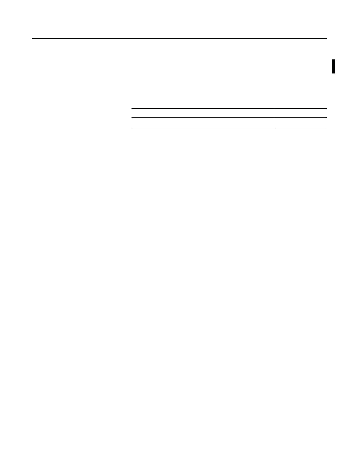
This document contains new and updated information. Changes are designated
by change bars in the outside margins.
This document contains these changes.
Topic Chapter
Updated supported controller models.
Cover
Rockwell Automation Publication CNET-UM001E-EN-P - June 2016 3
Page 4

Summary of Changes
Notes:
4
Rockwell Automation Publication CNET-UM001E-EN-P - June 2016
Page 5

Table of Contents
Preface
ControlNet Overview
Connect a Computer to the
ControlNet Network
Additional Resources ........................................................................................... 7
Chapter 1
Use ControlNet Communication Modules in a Control System ............... 9
Bridge Across Networks ................................................................................... 11
Exchange Information on a ControlNet Network ..................................... 14
ControlNet Network Capacity and Topology ............................................ 21
Chapter 2
Configure the ControlNet Communication Driver
in RSLinx Classic Software .............................................................................. 26
Network Update Time (NUT) ............................................................... 16
Requested Packet Interval (RPI) ............................................................. 17
Actual Packet Interval (API) .................................................................... 17
Schedule the Network ............................................................................... 18
Understand the Network Keeper ........................................................... 19
Default Parameters..................................................................................... 21
Topology ..................................................................................................... 21
Number of Nodes ...................................................................................... 24
Lengths ......................................................................................................... 24
Configure a ControlNet Module
Chapter 3
Use RSLogix 5000 Software ............................................................................ 29
Use RSNetWorx for ControlNet Software .................................................. 44
Configure the I/O Configuration Tree in Your Project ..................... 29
Add a
nd Configure a Local ControlNet Module ................................. 30
Add and Configure a Remote ControlNet Module ............................ 33
Download the Project to the Logix5000 Controller ............................ 36
Electronic Keying. ...................................................................................... 37
Schedule a ControlNet Network for the First Time ........................... 44
Schedule the Network Offline ................................................................. 45
Schedule the Network Online ................................................................. 49
Reschedule a ControlNet Network
that has Previously been Scheduled ......................................................... 53
Page 6

Table of Contents
Control I/O
Produce and Consume Tags
(interlock controllers)
Chapter 4
Set Up the Hardware ......................................................................................... 56
Requested Packet Interval (RPI) ..................................................................... 56
Communication Format .................................................................................. 57
Direct or Rack-optimized Connections .................................................. 58
Ownership ................................................................................................... 61
Add a Remote Adapter ..................................................................................... 63
Add Distributed I/O ......................................................................................... 63
Distributed I/O Communication Formats............................................ 65
Access Distributed I/O ..................................................................................... 65
Validate Connections ........................................................................................ 68
Chapter 5
Terminology ....................................................................................................... 71
Set Up the Hardware......................................................................................... 72
Determine Connections for Produced and Consumed Tags ..................... 73
Organize Tags for Produced or Consumed Data ......................................... 75
Adjust for Bandwidth Limitations .................................................................. 76
Produce a Tag ..................................................................................................... 77
Consume a Tag .................................................................................................. 79
Messaging
Communicate with PanelView
Terminals
Chapter 6
Set Up the Hardware ......................................................................................... 84
Guidelines for MSG Instructions ................................................................... 85
Determine Connections for Messages ............................................................ 86
Guidelines for Caching Message Connections ...................................... 86
Enter Message Logic .......................................................................................... 86
Add the ControlNet Modules and Remote Devices
to the Local Controller’s I/O Configuration ......................................... 87
Enter a Message ........................................................................................... 88
Configure a Message Instruction .................................................................... 88
Stagger the Messages.......................................................................................... 90
Chapter 7
Set Up the Hardware......................................................................................... 92
Determine Connections to PanelView Terminals ....................................... 93
Add a PanelView Terminal .............................................................................. 94
Organize Controller Data for a PanelView Terminal ................................. 96
Index ............................................................................................................................................................................................... 97
6
Rockwell Automation Publication CNET-UM001E-EN-P - June 2016
Page 7

Preface
Additional Resources
This manual describes how you can use ControlNet communication modules
with your Logix5000 controller.
Use this manual if you program applications that use a ControlNet network with
one of these Logix5000 controllers:
CompactLogix controller
•
•
ControlLogix controller
•
PowerFlex 700S with DriveLogix controller
•
SoftLogix5800 controller
Also be familiar with the following:
N
et
working concepts
•
•
RSLogix 5000 software
RSLinx Classic software
•
RSNetWorx for
•
ControlNet software
These documents contain additional information concerning related products
from Rockwell Automation.
Resource Description
ControlNet Modules Installation Instructions,
publication CNET-IN005
Industrial Automation Wiring and Grounding
Guidelines, publication 1770-4.1
Product Certifications website,
http://www.ab.com
Describes how to install 1756-CN2, 1756-CN2R,
1756-CN2RXT, 1756-CNB, 1756-CNBR, 1768-CNB,
and 1768-CNBR ControlNet modules.
Provides general guidelines for installing a Rockwell
Automation industrial system.
Provides declarations of conformity, certificates, and
other certification details.
You can view or download publications at http://www.rockwellautomation.com/
literature. To order paper copies of technical documentation, contact your local
Allen-Bradley distributor or Rockwell Automation sales representative.
Rockwell Automation Publication CNET-UM001E-EN-P - June 2016 7
Page 8

Preface
Notes:
8
Rockwell Automation Publication CNET-
UM001E-EN-P - June 2016
Page 9

Chapter
Use ControlNet Communication Modules in a Control System
9
1
ControlNet Overview
The ControlNet network provides high-speed transmission of time-critical I/O
and interlocking data and messaging data. This data transfer capability enhances
I/O performance and peer-to-peer communication in any system or application.
The Cont
unaffected as devices are connected or disconnected from it. This ensures
dependable, synchronized, and coordinated real-time performance.
The ControlNet network is most often used in these ways:
This chapter describes how you can use ControlNet modules in a network
control system.
Topic Page
rolNet network is highly deterministic and repeatable and remains
As the default network for the ControlLogix platform
•
•
As a backbone to multiple distributed DeviceNet networks
•
As a peer interlocking network
Use ControlNet
Communication Modules in
a Control System
Bridge Across Networks
Exchange Information on a ControlNet Network
ControlNet Network Capacity and Topology
You can fit various ControlNet modules into your control system.
Figure 1 on page 10 shows the following:
•
The controllers produce and consume tags among themselves.
•
The controllers initiate MSG instructions that send/receive data or
configure devices.
•
The computer uploads and downloads projects to the controllers.
The computerconfiguresdevices on the ControlNet network and
•
configures the network itself.
11
14
21
Rockwell Automation Publication CNET-UM001E-EN-P - June 2016 9
Page 10
Chapter 1
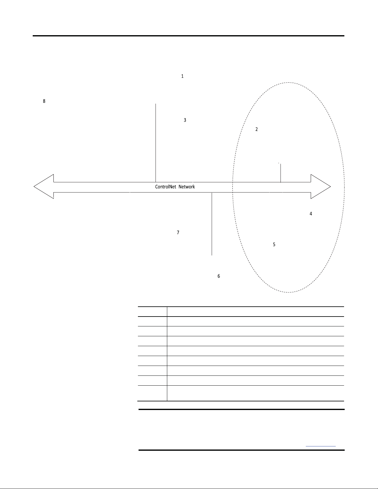
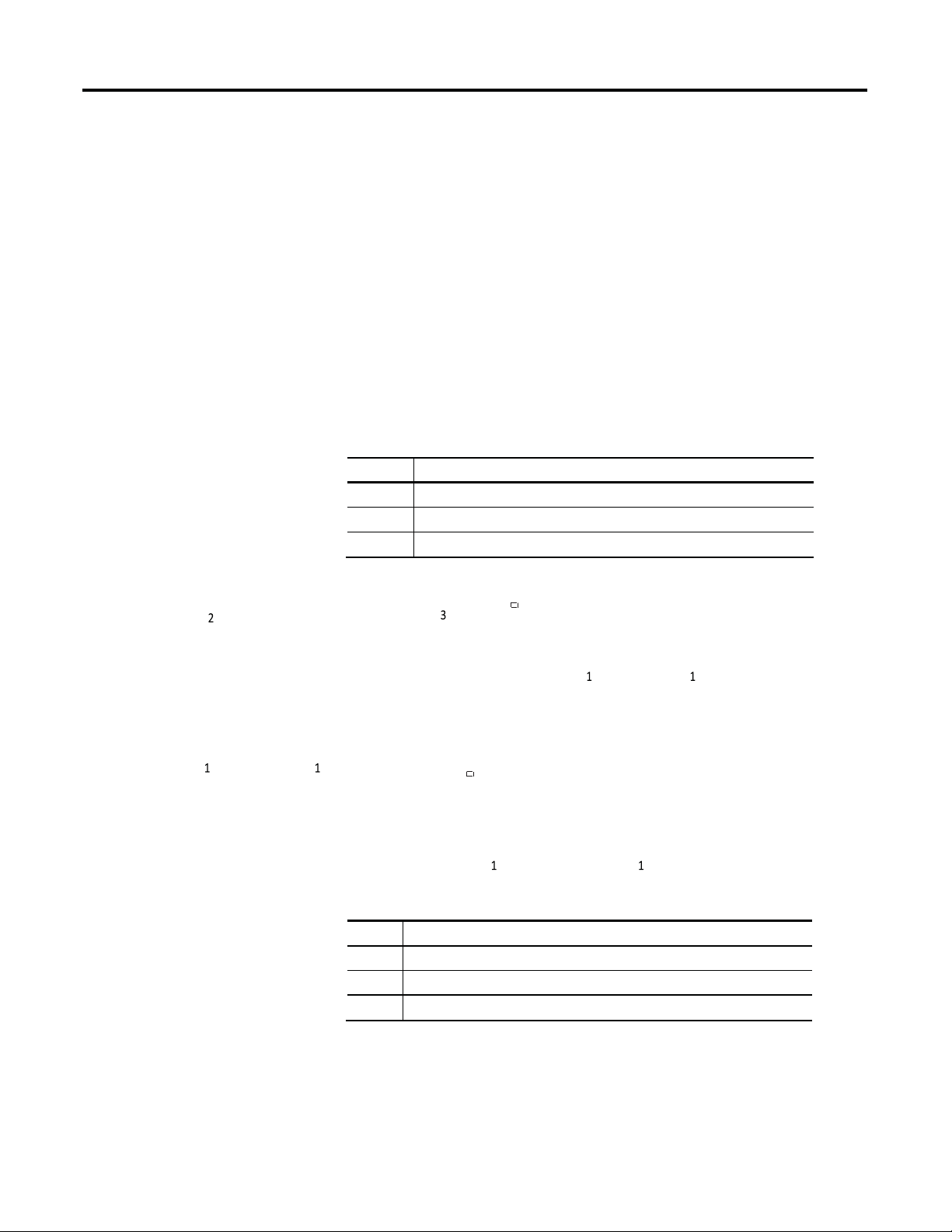
6 PanelView terminal
ControlNet Overview
Figure 1 - ControlNet Modules and the Control System Overview
10
Item Description
1
2
3
4
5
7
8
IMPORTANT
Rockwell Automation Publication CNET-
Personal computer running SoftLogix5800 controller with 1784-PCICS card
1756-CNB module (as an adapter) with 1756 I/O modules
PowerFlex 700S drive
1794-ACN15 adapter with 1794 I/O modules
1734-ACNR adapter with 1734 I/O modules
CompactLogix 1769-L35CR controller with local 1769 I/O modules
ControlLogix controller with 1756-CN2, 1756-CN2R, 1756-CNB, or 1756-CNBR module
as the scanner
For an enhanced redundancy system, you must use a 1756-CNB,
1756-CNBR, 1756-CN2 series B, or 1756-CN2R series B communication
module. The 1756-CN2 or 1756-CN2R series A module does not support
enhanced redundancy. For more information, refer to the ControlLogix
Enhanced Redundancy System User Manual, publication 1756-UM535.
UM001E-EN-P - June 2016
Page 11
ControlNet Overview
(2)
EtherNet/IP
Yes
Yes
Yes
Yes
Yes
Chapter 1
Bridge Across Networks
Some ControlNet modules support the ability to bridge or route communication
to and from different networks, depending on the capabilities of the platform and
communication devices.
IMPORTANT
You can only bridge across networks to communicate with devices. You
cannot bridge across networks to control I/O, even though RSLogix 5000
software can accept such a configuration in the I/O Configuration folder.
All I/O control must originate and end on the same physical network.
The following table describes how communication can bridge across networks.
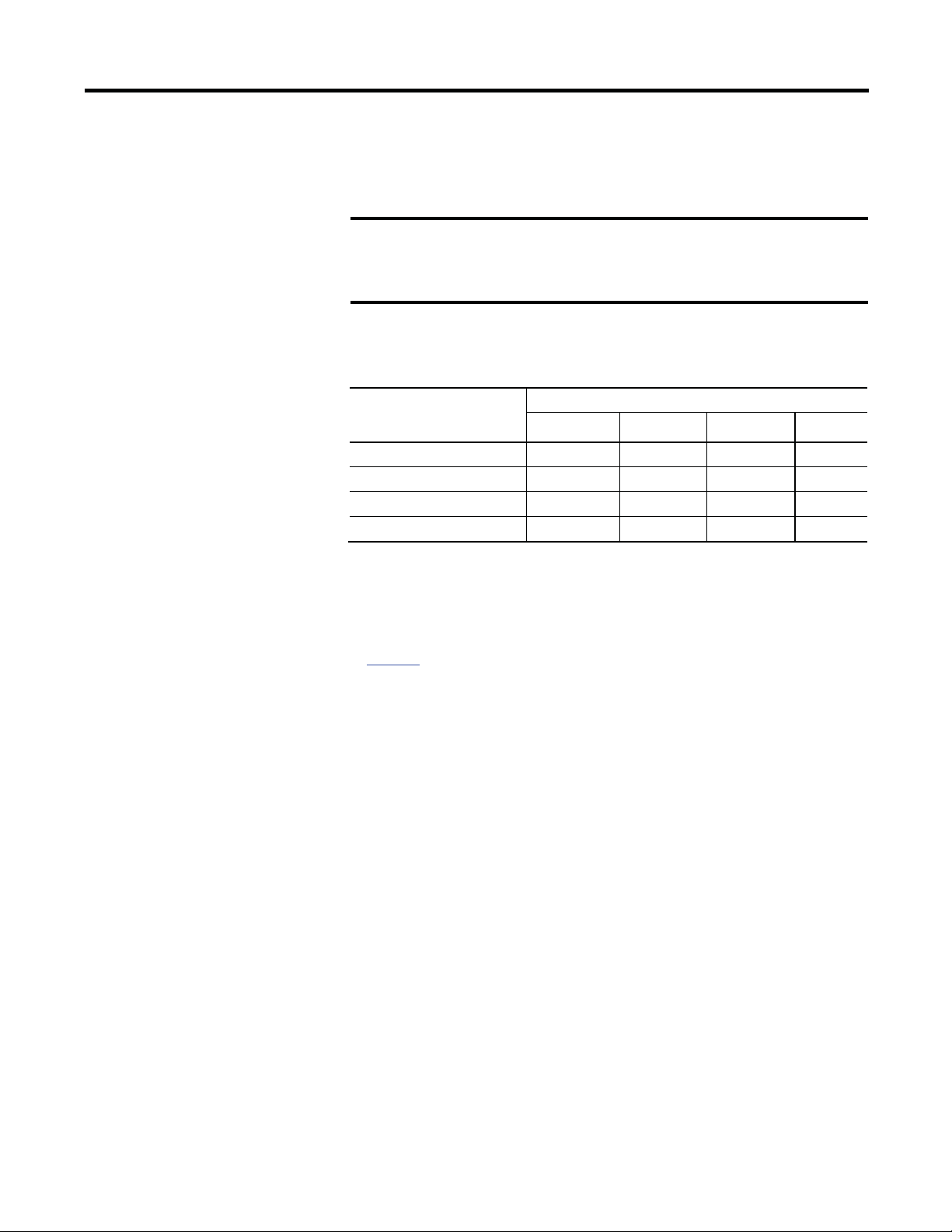
Table 1 - Bridging Across Networks
A device on this network Can communicate with a device on this network
EtherNet/IP ControlNet DeviceNet
ControlNet
DeviceNet No No Yes No
RS-232 Yes
(1) To use RSNetWorx for ControlNet software to configure and schedule a ControlNet network, we recommend
(2) Typically, this is a point-to-point connection between a Logix5000 controller and another device, such as a
Yes Yes Yes Yes
(1)
that you either connect to an EtherNet/IP network and bridge to a ControlNet network or use a 1784-U2CN
cable to connect directly to a ControlNet network.
PanelView Plus operator terminal.
Yes Yes
RS-232
In Figure 2, a workstation configures a drive on the DeviceNet network. The
workstation bridges from the ControlNet network to the DeviceNet network to
reach the drive. The bridge is a ControLogix chassis with ControlNet and
DeviceNet modules.
Rockwell Automation Publication CNET-UM001E-EN-P - June 2016 11
Page 12

Chapter 1
5
Item Description
Item Description
ControlNet Overview
Figure 2 - Drive Configuration on a DeviceNet Network
2
6
PWR
STS
1
Workstation
2
3
Bridge
IMPORTANT
PanelView terminal
The performance of a CompactLogix controller on a ControlNet network
degrades significantly if you use the controller as a bridge. Target
4
Drive
5
6
DeviceNet network
ControlNet network
bridging over a CompactLogix controller on a ControlNet network toward
applications that are not real-time dependent, such as RSLogix 5000
software program downloads.
In the example shown above, you can transfer messages from the DeviceNet
network through the Logix5000 controller to an RSView32 operator interface.
With a CompactLogix controller as a bridge, you can map the data into the
DeviceNet I/O image and then use RSLinx OPC to send the data to the
Logix5000 controller over the ControlNet network. This method conserves the
limited bridging resources of your CompactLogix controller.
12
Rockwell Automation Publication CNET-
UM001E-EN-P - June 2016
Page 13
ControlNet Overview
Item Description
Item Description
1 EtherNet/IP network
3 ControlNet Bridge in 1756 system
Destination
Modules for a 1768 CompactLogix
Modules for a 1769 CompactLogix
Modules for a ControlLogix
DeviceNet
•
1768-L43 or 1768-L45 controller
•
1769-L32C or 1769-L35CR controller
•
1756-CN2 module
Chapter 1
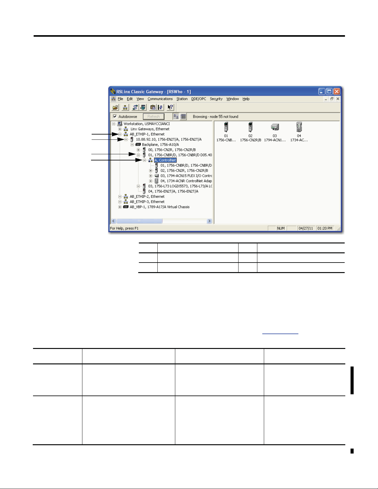
The following example shows how a DeviceNet bridge links to an EtherNet/IP
network in RSLinx software.
Figure 3 - EtherNet/IP Bridge Linking to a ControlNet Network
1
2
3
4
Table 2 - Bridges from a ControlNet Network
Network
EtherNet/IP
System
•
1768-CNB(R) module
•
1769-SDN scanner
•
1768-L43 or 1768-L45 controller
•
1768-CNB(R) module
•
1768-ENBT module
2
EtherNet/IP bridge in 1756 system
4
ControlNet network
The following tables list the possible bridges between communication networks.
Note that you can bridge from a ControlNet network to an Ethernet network
and from an Ethernet network to a ControlNet via a SoftLogix virtual chassis.
However, the products and methods you must use to do so are more detailed than
can be effectively described in the following tables. For more information on how
to bridge from one network to another via a SoftLogix virtual chassis, see the
SoftLogix5800 System User Manual, publication 1789-UM002.
System
•
1769-SDN scanner or 1788-CN2DN
(1)
module
Not applicable
Chassis
•
1756-CN2R module
•
1756-CNB module
•
1756-CNBR module
•
1756-DNB module
•
1756-CN2 module
•
1756-CN2R module
•
1756-CNB module
•
1756-CNBR module
•
1756-ENBT module
•
1756-EN2T module
•
1756-EN2TR module
•
1756-EN3TR module
(1) Can serve as a dedicated standalone bridge from a ControlNet network to a DeviceNet network.
Rockwell Automation Publication CNET-UM001E-EN-P - June 2016 13
Page 14

Chapter 1
•
1768-L43 or 1768-L45
•
1756-CN2 module
•
1768-L43 or 1768-L45
•
1769-L32E or 1769-L35E
•
1756-DNB module
•
1769-L23E-QB1B controller
ControlNet Overview
Table 3 - Bridges from an EtherNet/IP Network
Destination
Network
ControlNet
DeviceNet
(1) Can serve as a dedicated standalone bridge from an EtherNet/IP network to a DeviceNet network.
Modules for a 1768
CompactLogix System
controller
•
1768-ENBT module
•
1768-CNB(R) module
controller
•
1768-ENBT module
•
1769-SDN scanner
Exchange Information on a ControlNet Network
Modules for a 1769
CompactLogix System
Not applicable
controller
•
1769-SDN scanner or 1788EN2DN module
ControlNet communication modules use a message-based protocol that
implements a relative path to send a message from the producing module in a
system to the consuming modules. This protocol also lets you communicate
(1)
between devices on a ControlNet, DeviceNet, or EtherNet/IP network without
writing additional application code.
Modules for a
ControlLogix Chassis
•
1756-CN2R module
•
1756-CNB module
•
1756-CNBR module
•
1756-ENBT module
•
1756-EN2T module
•
1756-EN2TR module
•
1756-EN3TR module
•
1756-ENBT module
•
1756-EN2T module
•
1756-EN2TR module
•
1756-EN3TR module
Modules for a 1769
CompactLogix Packaged
Controller System
Not applicable
•
1769-L23E-QBFC1B controller
•
1769-L23-QBFC1B controller
•
1769-SDN scanner
With unscheduled data, the device from which a message originates, such as a
Logix5000 controller, contains the path information that makes sure the message
reaches its consumers.
For a full explanation of unscheduled and scheduled data, see Network Update
Time (NUT ) on page 16.
Because the producing module holds this information, other modules along the
path simply pass the information along and do not need to store it. The
significant benefits include the following:
•
You do not need to configure routing tables in the bridging module, which
greatly simplifies maintenance and module replacement.
•
You maintain full control over the route taken by each message, which
enables you to select alternative paths for the same end module.
Scheduled data in Logix-based systems use the producer/consumer networking
model instead of a source/destination (master/slave) model. The producer/
consumer model reduces network traffic and increases transmission speed.
14
Rockwell Automation Publication CNET-
UM001E-EN-P - June 2016
Page 15

ControlNet Overview
Chapter 1
In traditional I/O systems, controllers poll input modules to obtain their input
status. In a Logix system, digital input modules are not polled by a controller.
Instead, they produce (multicast) their data either upon a change of state (COS)
or periodically. The frequency of update depends upon the options chosen during
configuration and where on the network the input module resides. The input
module, therefore, is a producer of input data and the controller is a consumer of
the data.
The controller can also produce data for other controllers to consume. The
produced and consumed data is accessible by multiple controllers over the Logix
backplane and the ControlNet network. This data exchange conforms to the
producer/consumer model.
A Cont
rolNet network link’s most important function is to transport timecritical control information, such as I/O data and control interlocking. Other
information that is not time-critical, such as program uploads and downloads, is
also transported but does not interfere with time-critical messages because a
ControlNet network can transmit scheduled and unscheduled data.
On a ControlNet network link, nodes transfer information by establishing
connections. Each message sent by a producer contains a Connection ID (CID).
Nodes that have been configured to recognize the CID consume the message,
becoming consumers themselves.
Media access to the network is controlled by a time-slice access algorithm,
Concurrent Time Domain Multiple Access (CTDMA), which regulates a node’s
opportunity to transmit in each network update interval (NUI). You configure
how often the NUI repeats by selecting a network update time (NUT) in
milliseconds.
Rockwell Automation Publication CNET-UM001E-EN-P - June 2016 15
Page 16
Chapter 1
Parts of NUT
Functions
Scheduled
On a sequential, rotating basis, every scheduled node can transmit data once per
ControlNet Overview
Network Update Time (NUT)
The network update time (NUT) is the shortest interval in which data can be
sent on a ControlNet network. It represents the fastest possible update rate for
scheduled data transfers on that network. For example, a network that runs with a
five ms NUT cannot send scheduled data at a rate faster than five ms. It can,
however, send data at a slower rate. The minimum NUT you can specify is two
ms. The NUT is divided into a three-part structure.
Table 4 - NUT Structure
NUT.
Unscheduled
Maintenance
Time-critical information is sent during this part of the interval.
All nodes transmit on a sequential, rotating basis, the rotation repeating itself
until the time allotted for this portion is used up.
The number of scheduled transmissions determines the time available for
unscheduled transmissions. On a ControlNet network, at least one node can
transmit unscheduled data every NUT.
Information that can be delivered without time constraints is sent during this
part of the interval.
The node with the lowest address transmits information to keep the other nodes
synchronized. This time is automatically subtracted from your NUT. However, the
time required for network maintenance is brief (microseconds) when compared
to that used for the scheduled and unscheduled portions of the NUT.
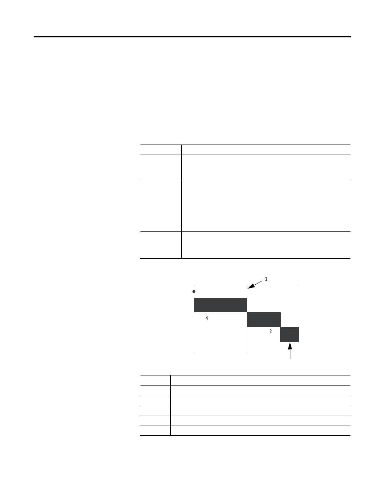
Figure 4 - NUT Structure
5
Item Description
1
2
3
4
5
Start
Boundary moves according to scheduled traffic load
Unscheduled traffic
Network maintenance
Scheduled traffic. Each device transmits only once
3
16
Rockwell Automation Publication CNET-
UM001E-EN-P - June 2016
Page 17

ControlNet Overview
Chapter 1
Requested Packet Interval (RPI)
The RPI is the update rate specified for a particular piece of data on the network.
By using a rack-optimized connection, the RPI can specify the rate for an entire
rack of I/O. With a direct connection, the RPI can specify the rate for a
particular module or peer-to-peer data. When you add a module to the I/O
configuration of a controller, you must configure the RPI, specifying how often
to produce data for that module. For example, if you specify an RPI of 50 ms,
every 50 ms the I/O module sends its data to the controller or the controller
sends its data to the I/O module.
Set the RPI only as fast as needed by the application. The RPI also determines the
number of packets per second that the module will handle on a connection. Each
module has a limit of how many packets it can handle per second. If you exceed
this limit, the module cannot open any more connections.
A faster RPI consumes more network bandwidth. So, to avoid wasting network
bandwidth, set the RPI only as fast as is necessary. For example, if your
application uses a thermocouple module that has data change every 100 ms, do
not set the RPI for that node at 5 ms because the network bandwidth is used to
transmit mostly old data.
IMPORTANT
You cannot set the RPI to a rate faster than the NUT. The network cannot
send data at a rate that is faster than the NUT.
When you run RSNetWorx for ControlNet software, an Actual Packet Interval
(API) is calculated. The API is equal to or faster than the RPI.
Actual Packet Interval (API)
The API is the actual update rate for a particular piece of data on the network. A
ControlNet network sets this rate equal to or faster than the RPI, based on the
binary multiple of the NUT, which is the next fastest rate at which a module can
send data. If this cannot be done, a ControlNet network provides reports that it
cannot support the configuration.
Rockwell Automation Publication CNET-UM001E-EN-P - June 2016 17
Page 18
Chapter 1
NUT
Multiple
Rate at Which Module Can
5 ms
1 5 ms
ControlNet Overview
Understand the Effect of the NUT on the API
This e
xample illustrates how the NUT affects the API. A module on the network
can produce data only at binary multiples of the NUT to a maximum of the
NUT multiplied by 128. These multiples are referred to as rates on a ControlNet
network. Therefore, with a NUT of 5 ms, the module can send data at these rates.
Table 5 - NUT Example Data Rates
Send Data
2
4
8
16
32
64
128
In this example, if you specify an RPI of 25 ms, then the network produces an
API of 20 ms, which is the next fastest rate at which the module can send data.
The module places the data on the network at every fourth network update
10 ms
20 ms
40 ms
80 ms
160 ms
320 ms
640 ms
interval to produce the 20 ms API. Similarly, if you specify an RPI of 150 ms, the
network produces an API of 80 ms.
Schedule the Network
Connections over a ControlNet network can be one of the following:
•
Scheduled—Data transferred at specific times.
Unscheduled—Data transferred when the network can accommodate the
•
transfer.
To use scheduled connections, you must schedule the ControlNet network via
RSNetWorx for ControlNet software. For more information on how to schedule
a ControlNet network with RSNetWorx for ControlNet software, see the section
Use R SNetWorx for ControlNet Software on page 44.
You must use RSNetWorx for ControlNet software to enable any connection in a
remote chassis. In addition, RSNetWorx software transfers configuration
information for the remote modules, verifies and saves NUT and other userspecified network parameters, and establishes a schedule that is compliant with
the RPI and other connection options specified for each module.
18
Rockwell Automation Publication CNET-
UM001E-EN-P - June 2016
Page 19

ControlNet Overview
Chapter 1
IMPORTANT
Control of Scheduled I/O
RSNetWorx for ControlNet software must be run whenever a
scheduled connection is added to, removed from, or changed in your
system.
Scheduled connections let you send and receive data repeatedly at a
predetermined rate. You can use the 1756-CNB or the 1756-CN2 module to
control scheduled I/O when you use it in conjunction with a ControlLogix
controller. When you place the module in the I/O configuration list of a
ControlLogix controller and configure a second ControlLogix chassis with a
remote 1756-CNB or 1756-CN2 module on the same ControlNet network, you
can perform remote control operations on the I/O, or to a second controller in
the second chassis.
In this case, the ControlLogix controller and the 1756-CN2 module in the local
chassis together act as a scanner, while the 1756-CN2 module in the remote
chassis with the I/O plays the role of an adapter.
Understand the Network Keeper
Every ControlNet network requires at least one module to store programmed
parameters for the network and configures the network with those parameters
when the module is started. This module is called a keeper because it keeps the
network configuration. RSNetWorx for ControlNet software configures the
keeper.
To avoid a single point of failure, a ControlNet network supports multiple
redundant keepers. These ControlNet communication modules are keepercapable devices:
•
1756-CN2 and 1756-CN2R modules
•
1756-CNB and 1756-CNBR modules
•
1768-CNB and 1768-CNBR modules
•
1769-L32C and 1769-L35CR controllers
•
1784-PCICS and 1784-PKTCS cards
•
1788-CNx cards
PLC-5C module
•
On a multi-keeper network, any keeper-capable module can keep the network at
any legal node address (01...99). The multi-keeper-capable node with the lowest
node address becomes the active keeper provided it is valid. It has been
configured by RSNetWorx for ControlNet software and that configuration is the
same as that of the first keeper that became active after the network was formed
or reconfigured by RSNetWorx software.
Rockwell Automation Publication CNET-UM001E-EN-P - June 2016 19
Page 20
Chapter 1
ControlNet Overview
If the active keeper is taken off the network, a valid back-up keeper can take over
for it and continue to act as keeper. As long as at least one valid multi-keeper
device is present on the network, new scheduled connections can be established.
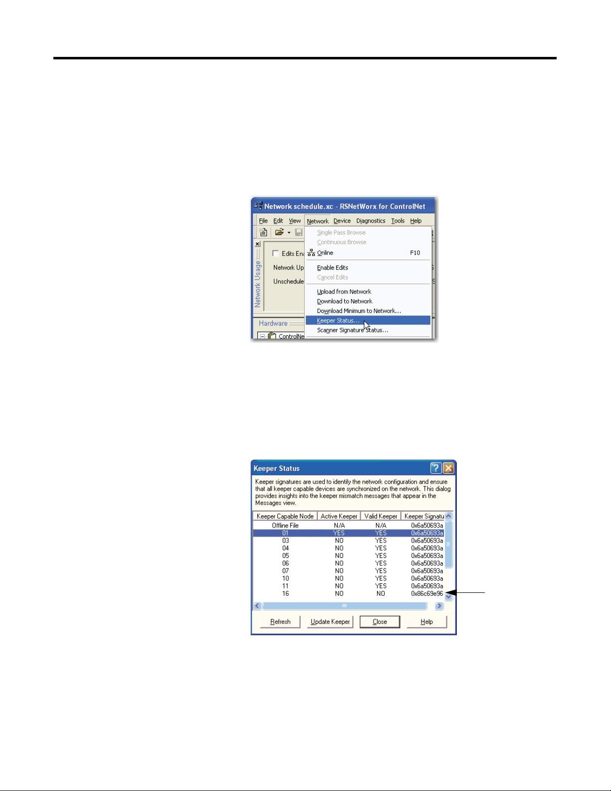
To review the valid keeper devices on your network, follow this procedure in
RSNetWorx for ControlNet software.
1.
From the Network menu, choose Keeper Status.
2.
Review the keeper devices on the Keeper Status dialog box.
On a typical net
•
work, the following must be true:
There must be only one active valid keeper.
All other keepers must be valid. If a keeper is not valid, it cannot
•
perform any scheduled communication. However, all unscheduled
communication occurs as expected.
The keeper signature, shown in hex, must be the same for all nodes.
•
Node 16 is
a valid keeper.
not
20
Rockwell Automation Publication CNET-
UM001E-EN-P - June 2016
Page 21

ControlNet Overview
Chapter 1
Default Parameters
When a ControlNet network is first established, it relies on a default set of
parameters capable of sending only unscheduled data. Default parameters in all
ControlNet devices include the following:
•
Network Update Time (NUT) = 100 ms
Scheduled MaximumNode Address (SMAX) = 1
•
The SMAX is the highest network address of a node that can use the
scheduled service.
Unscheduled Maximum Node Address (UMAX) = 99
•
The UMAX is the highest network address of a node that can
communicate on a ControlNet network. The UMAX must be set equal to
or higher than the SMAX.
Assumed maximum cable lengths and maximum number of repeaters
•
With this default ControlNet network, you can have unscheduled
communication between the various devices on the network by using
RSLogix 5000 software and RSLinx software.
IMPORTANT
To improve performance, configure a ControlNet network with
RSNetWorx for ControlNet software. We recommend these settings:
•
Set the Unscheduled Maximum Node Address (UMAX) equal to
the highest node address on the network. Leaving this parameter
at the default value of 99 wastes bandwidth and reduces system
performance.
Set the Scheduled Maximum Node Address (SMAX) to a value
•
three or four above the highest scheduled node address, so you
can expand the network in the future.
Also, be aware that each skipped node will subtract a small amount
of bandwidth from the network.
ControlNet Network Capacity and Topology
When planning a ControlNet network, consider these factors:
•
Topology
•
Number of nodes
•
Distances
Connections
•
Topology
A ControlNet network supports a variety of topologies, including trunkline/
dropline, star, tree, and ring redundancy. In its simplest form, a ControlNet
network is a trunkline to which you connect nodes with a tap and a one-meter
dropline.
Rockwell Automation Publication CNET-UM001E-EN-P - June 2016 21
Page 22
Chapter 1
ControlNet Overview
3
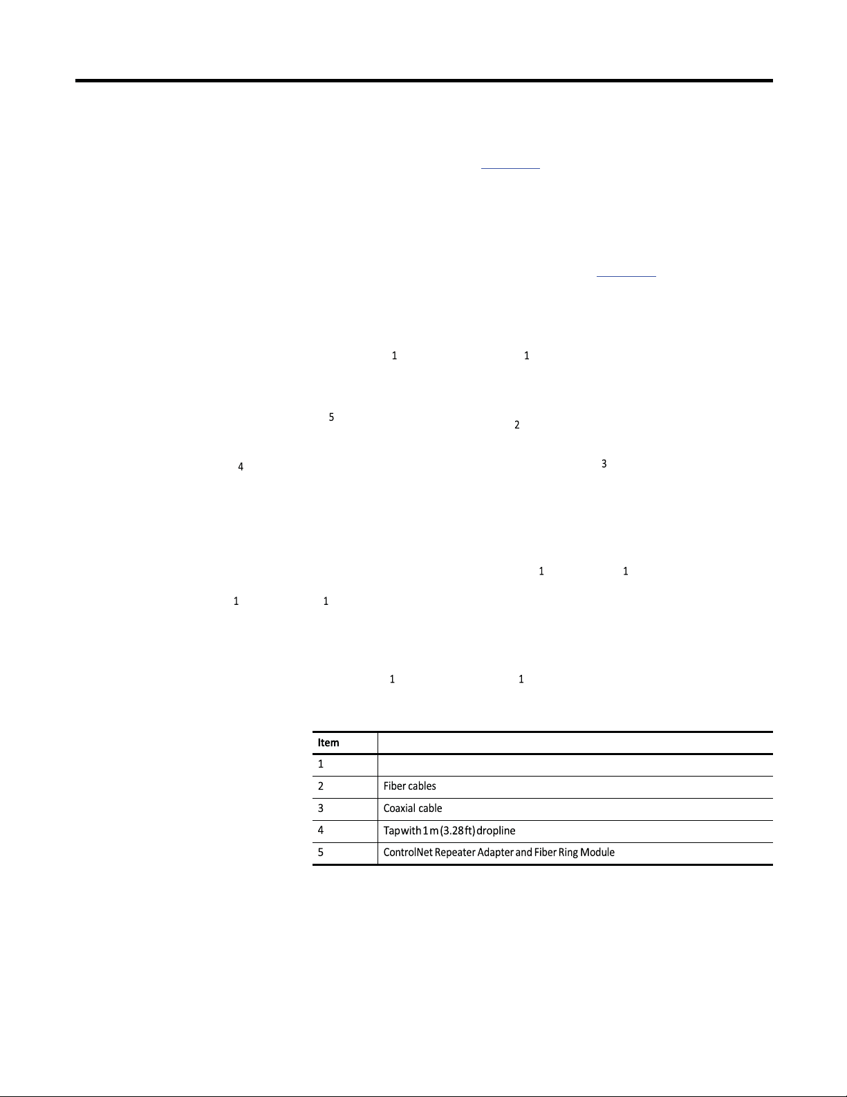
Figure 5 - Example ControlNet Network Trunkline/Dropline Topology
1
2
2
Item Description
1
2
Node
3
Trunkline
Tap with dropline
2
2
Figure 6 - Example ControlNet Network Star Topology
22
Item Description
1
Node
2
3
Rockwell Automation Publication CNET-
Tap with 1 m (3.28 ft) dropline
Coaxial repeater
UM001E-EN-P - June 2016
Page 23
ControlNet Overview
Description
Node
Chapter 1
TIP
Coax repeaters are typically used in trunkline and star topologies. See
the ControlNet Coax Media Planning and Installation Guide,
publication CNET-IN002, for more specific information on coax
topologies you can create.
With fiber media, you can configure your network in trunkline, star,
and ring topologies. Only the 1786-RPFRL and 1786-RPFRXL repeaters
support a ring topology.
For more information, consult the ControlNet Fiber Media Planning
and Installation Guide, publication CNET-IN001.
Figure 7 - Example ControlNet Network Ring Topology
Rockwell Automation Publication CNET-UM001E-EN-P - June 2016 23
Page 24
Chapter 1
S
e
g
m
en
t
Le
ng
th
m
(ft
)
ControlNet Overview
Number of Nodes
Each ControlNet network supports up to 99 nodes. Logix5000 controllers
support multiple ControlNet networks, providing the flexibility to add nodes to
a ControlNet network or boost performance.
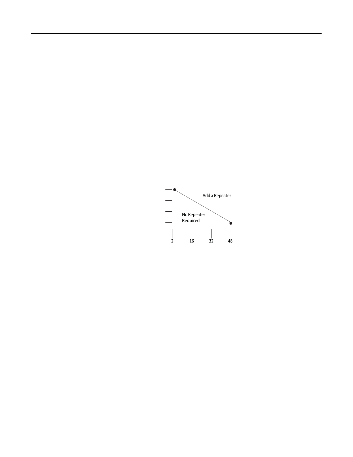
Lengths
In a ControlNet network, the maximum length depends on the number of nodes
on a segment; a segment is a section of trunk between two terminators. Use
repeaters to add segments or increase length.
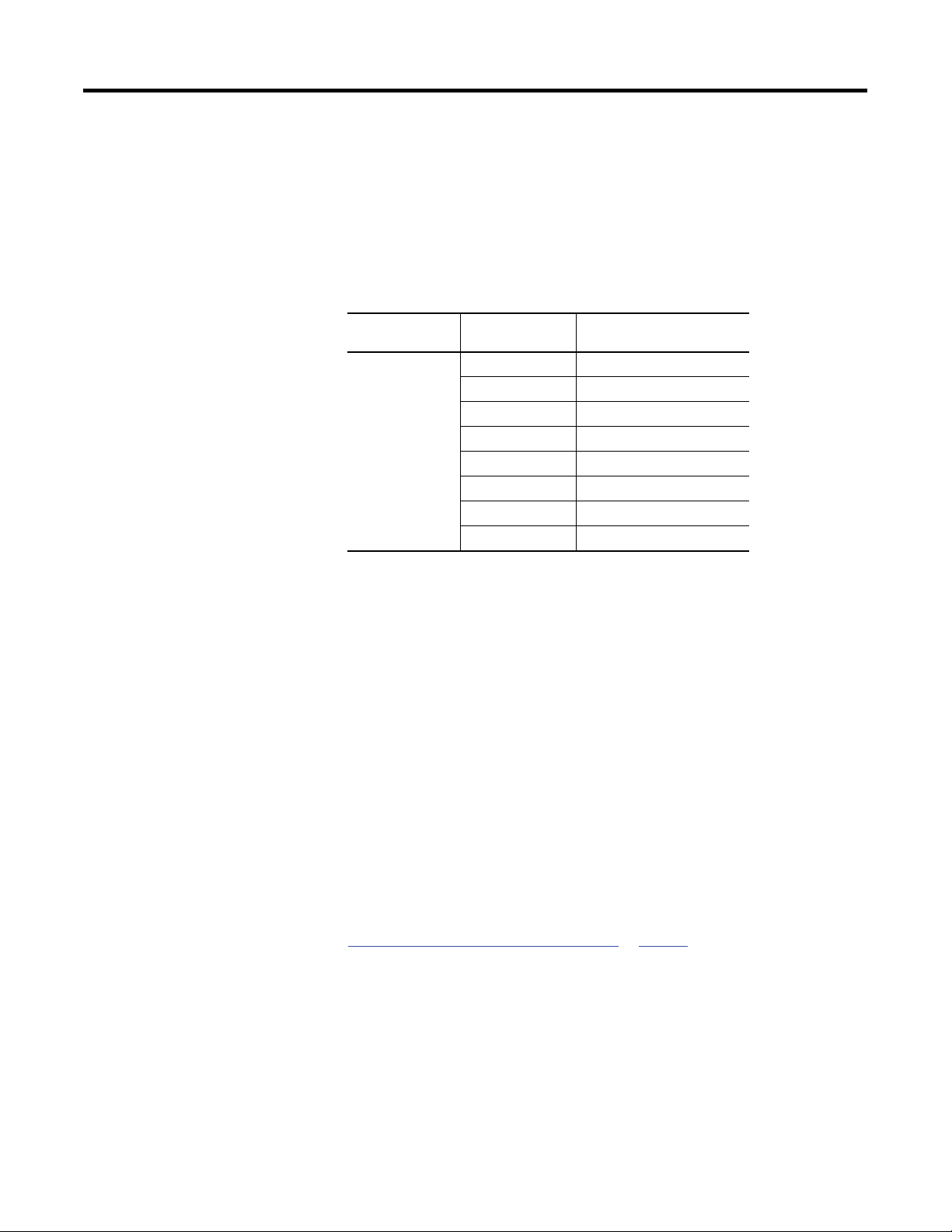
Figure 8 - Maximum Length of a ControlNet Network
Maximum Allowable Segment Length = 1000 m (3280 ft) - 16.3 m (53.4 ft) X [Number of Taps - 2]
1000 (3280)
750 (2460)
500 (1640)
250 (820)
24
This graph assumes that a 1786-RG6 cable is being used.
Rockwell Automation Publication CNET-
UM001E-EN-P - June 2016
Page 25
Chapter
Topic
Page
Configure the ControlNet Communication Driver in RSLinx Classic Software
26
2
Connect a Computer to the ControlNet
Network
This chapter explains how to set up a computer to operate on a ControlNet
network.
You need to load a ControlNet communication driver for a computer to
communicate with other devices on a ControlNet network. A computer uses this
driver to do the following:
•
Upload and download controller projects over ControlNet via RSLogix
5000 software.
•
Schedule the ControlNet network via RSNetWorx for ControlNet
software.
•
Operate an HMI type application.
Depending on the connection device, you can use one of these drivers:
•
1784-PCIC or 1784-PCICS card—You must configure the driver in
RSLinx Classic software, as described on page 26
•
USBCIP driver—Use only with a 1784-U2CN USB-to-ControlNet
cable. You are not required to configure the driver in RSLinx Classic
software.
IMPORTANT
After preparing the driver for use, connect the card or cable to the computer, and
then connect the computer to the network.
If you are running RSLinx Classic software, version 2.51, 2.52, or
2.53, you must manually install the USBCIP driver. To obtain the
driver installation package, refer to answer ID 55431 on the
Rockwell Automation Knowledgebase at
http://www.rockwellautomation.com/knowledgebase.
If you are running RSLinx Classic software, version 2.54 or later,
the USBCIP driver is already installed on the computer.
.
Rockwell Automation Publication CNET-UM001E-EN-P - June 2016 25
Page 26
Chapter 2
Connect a Computer to the ControlNet Network
Configure the ControlNet Communication Driver in RSLinx Classic Software
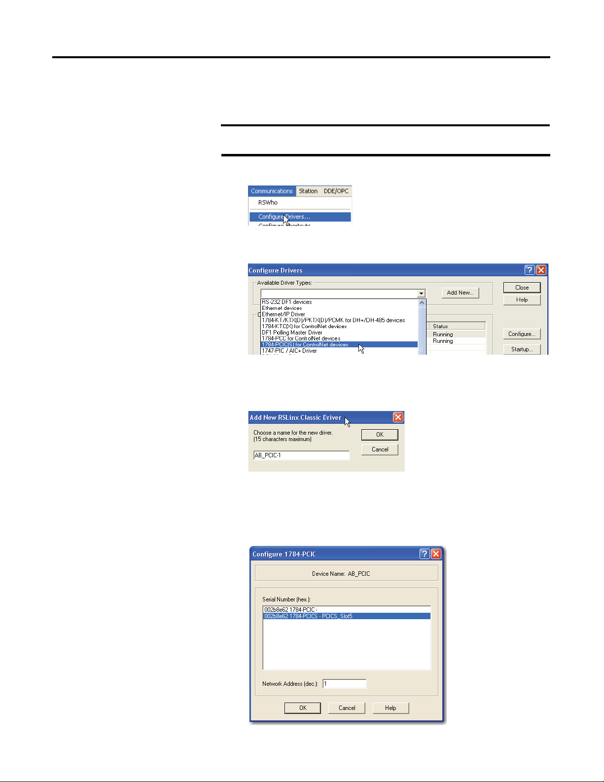
To configure a ControlNet communication driver, perform this procedure in
RSLinx Classic software.
IMPORTANT
1.
From the Communications menu, choose Configure Drivers.
2.
From the Available Driver Types pull-down menu, choose a driver for a
ControlNet devi
3.
Click Add New.
If you are using a 1794-U2CN cable to connect to the network, you are
not required to configure the driver.
ce.
The Add New RSLinx Driver dialog box appears. The driver name
defaults to AB_xxx.
4.
Type the name of the new ControlNet driver.
5.
Click OK.
The Configure Device dialog box appears. The appearance of this screen
varies, depending on the ty
pe of card used.
26
Rockwell Automation Publication CNET-
UM001E-EN-P - June 2016
Page 27

Connect a Computer to the ControlNet Network
6.
If your computer contains multiple cards, from the Serial Number (hex)
field, choose the co
7.
In the Network Address (dec) box, type the correct network address.
8.
Click OK.
rrect card.
The driver is now available and you can choose the ControlNet port from
Who Active in RS
Logix 5000 software.
Chapter 2
Rockwell Automation Publication CNET-UM001E-EN-P - June 2016 27
Page 28

Chapter 2
Connect a Computer to the ControlNet Network
Notes:
28
Rockwell Automation Publication CNET-
UM001E-EN-P - June 2016
Page 29
Chapter
Topic
Page
Use RSLogix 5000 Software
29
3
Configure a ControlNet Module
This chapter explains how to configure a ControlNet communication module to
operate on a ControlNet network.
Use RSNetWorx for ControlNet Software
IMPORTANT
The example configuration process shown in this chapter uses a
1756-CN2R/B ControlLogix ControlNet bridge module in a
ControlLogix controller project.
However, the overall configuration process, described in
Configure the I/O Configuration Tree in Your Project, generally
applies to any of the ControlNet communication modules covered
in this manual.
44
Use RSLogix 5000 Software
Use RSLogix 5000 software to configure the I/O tree in your project.
Configure the I/O Configuration Tree in Your Project
When y
communication module, you must perform these tasks.
ou use RSLogix 5000 software to configure a ControlNet
1.
Add and Config ure a Local ControlNet Module.
2.
Add and Config ure a Remote ControlNet Module.
IMPORTANT
3.
Download the Project to the Logix5000 Controller.
There are some differences between configuring a local
ControlNet communication module and configuring a remote
ControlNet communication module. Those differences are
covered later in this chapter.
Rockwell Automation Publication CNET-UM001E-EN-P - June 2016 29
Page 30
Chapter 3
Configure a ControlNet Module
Add and Configure a Local ControlNet Module
After you have started RSLogix 5000 software and created a controller project,
you can add ControlNet communication modules. A local ControlNet module is
a module that resides in the same chassis as the controller.
IMPORTANT
When you create a new RSLogix 5000 project with the CompactLogix
1769-L32C or 1769-L35CR controller, the Controller Organizer creates a
ControlNet port in the local chassis. In this case, you do not need to add a
separate local communication module.
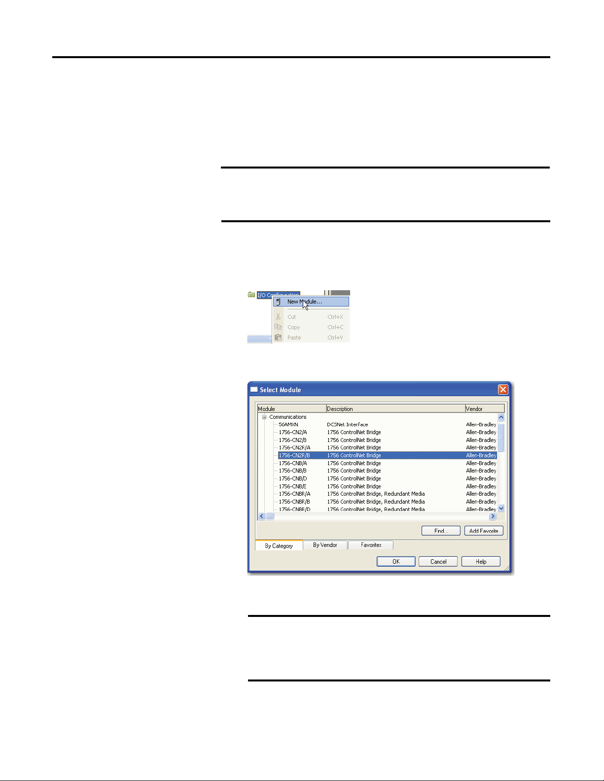
To add a local ControlNet module, follow this procedure.
1.
In RSLogix 5000 software, right-click I/O configuration and choose New
Module.
2.
From the Select Module Type dialog box, expand Communications,
choose the local C
ontrolNet communication module, and then click OK.
30
IMPORTANT
Rockwell Automation Publication CNET-
This procedure shows the New Module dialog box for a
1756-CN2R/B. However, various dialogs appear during
configuration depending on the ControlNet module you select. For
help configuring a module, refer to the online help in
RSLogix 5000 software.
UM001E-EN-P - June 2016
Page 31

Configure a ControlNet Module
Field
Action
Name
Type a name for the local ControlNet module.
Logix5000 Controller
Local ControlNet Communication Module
1768 CompactLogix
1768-CNB, 1768-CNBR
1769 CompactLogix
1769-L32C and 1769-L35CR controllers have a built-in ControlNet port
Chapter 3
This table lists the ControlNet communication modules available locally
in the local chassis, computer, or controller with each Logix5000
controller.
Table 6 - ControlNet Communication Modules Available Locally
ControlLogix
SoftLogix
3.
Complete the fields on the New Module dialog box and then click OK.
Node
Description
Slot
Revision
Electronic Keying
Open Module Properties
1756-CN2, 1756-CN2R, 1756-CNB, 1756-CNBR
1784-PCIC, 1784-PCICS
Enter the module’s node number on the network.
Type a description of the local ControlNet module.
Enter the module’s slot number in the chassis.
Choose a major and minor revision of RSLogix 5000 software.
Choose a keying option, as described in Electronic Keying on page 37.
Leave the box checked to configure connection properties in the next
step.
Rockwell Automation Publication CNET-UM001E-EN-P - June 2016 31
Page 32

Chapter 3
Configure a ControlNet Module
4.
On the Module Properties dialog box, configure the connection properties
and then click A
pply.
Connection Property
Inhibit Module
Major Fault On Controller If
Connection Fails While In Run Mode
Action
If the module does
controller, check the checkbox.
or
If the module needs to communicate with the controller,
leave the checkbox cleared.
IMPORTANT:
leave the checkbox cleared.
If you want the controller to produce a major fault if the
connection to the local communication module fails in Run
mode, check the checkbox.
or
If you want the controller to continue operating if the
connection to the local communication module fails in Run
mode, leave the checkbox cleared. Use ladder logic to
monitor the connection.
not
need to communicate with the
When you test this portion of the system,
32
Rockwell Automation Publication CNET-
UM001E-EN-P - June 2016
Page 33

Configure a ControlNet Module
Chapter 3
Add and Configure a Remote ControlNet Module
After you have added the local ControlNet communication module, you must
add remote ControlNet communication modules. A remote ControlNet module
is a module that resides in a chassis separate from the controller.
To add a remote ControlNet module, perform this procedure.
1.
In RSLogix 5000 software, right-click the local ControlNet
communication mod
2.
From the Select Module Type dialog box, expand Communications, select
a remote ControlNet co
ule and choose New Module.
mmunication module, and then click OK.
You can connect any remote ControlNet communication module to a
local ControlNet com
munication module.
IMPORTANT
Rockwell Automation Publication CNET-UM001E-EN-P - June 2016 33
This procedure shows the New Module dialog box for a
1756-CN2R/B. However, various dialogs appear during
configuration depending on the ControlNet module you select. For
help configuring a module, refer to the online help in
RSLogix 5000 software.
Page 34

Chapter 3
Field
Action
Name
Type a name for the local ControlNet module.
Configure a ControlNet Module
3.
Complete the fields on the New Module dialog box and then click OK.
Node
Description
Chassis Size
Comm Format
Slot
Revision
Electronic Keying
Open Module Properties
Enter the module’s node number on the network.
Type a description of the local ControlNet module.
Enter the total number of slots in the chassis.
Choose a communication format, as described in Communication
Format below.
You do not need to assign a communication format for 1784-PCIC,
1784-PCICS, or 1788-CNx cards.
Enter the module’s slot number in the chassis.
Choose a major and minor revision of RSLogix 5000 software.
Choose a keying option, as described in Electronic Keying on page 37.
Leave the box checked to configure connection properties in the next
step.
34
Communication Format
The communication format determines the following:
•
What configuration options are available
For example, if the module uses None, then you do not have to configure
an RPI rate on the Module Properties dialog box.
•
What type of data is transferred between the owner-controller and I/O
connected via the communication module
•
What tags are generated when configuration is complete
•
The type of connection between the owner-controller and the I/O
connected via the communication module
Rockwell Automation Publication CNET-
UM001E-EN-P - June 2016
Page 35

Configure a ControlNet Module
Communication Format
Function
Effect on RPI
Rack-optimized
The communication module creates a rack image and
You can specify an RPI that meets this criteria:
0
The communication format setting also affects the RPI rate.
Chapter 3
Table 7 - Communication Formats
Listen-only rack-optimized (not
available on all ControlNet
communication modules)
None
Connection Property
Requested Packet Interval (RPI)
Inhibit Module
Major Fault On Controller If Connection Fails While In
Run Mode
Use Scheduled Connection over ControlNet
Action
returns I/O data in the rack image to the owner-controller.
This option is available only for digital I/O modules.
Remember that diagnostic I/O modules will not return
diagnostic data when you use this format.
The communication module creates a rack image and
returns I/O input data in the rack image to the ownercontroller.
The difference between this choice and rack-optimized is
that the I/O data in the rack image is returned to a
controller that does not control the outputs but is listening
only to its input data.
No RPI is required.
•
Equal to or greater than the NUT
•
4.
On the Module Properties dialog box, configure the connection properties
and then click A
Type the requested packet interval between 2.0…750.0 ms.
If your module uses one of the rack-optimized communication formats, the RPI must be equal
to or greater than the ControlNet Network Update Time (NUT).
If the module does
or
If the module needs to communicate with the controller, leave the checkbox cleared.
IMPORTANT:
If you want the controller to produce a major fault if the connection to the local
communication module fails in Run mode, check the checkbox.
or
If you want the controller to continue operating if the connection to the local communication
module fails in Run mode, leave the checkbox cleared. Use ladder logic to monitor the
connection.
Check the box if you want to explicitly schedule the network connection.
Note the following:
•
The checkbox is enabled when the connection for the module crosses ControlNet and the
module supports unscheduled connections.
•
The checkbox is checked and disabled when the connection to the module crosses
ControlNet, and the module does not support unscheduled connections, and therefore,
must be scheduled.
•
The checkbox is cleared and disabled when the connection to the module does not cross
ControlNet, or the connection crosses ControlNet but does not need to be scheduled.
When you test this portion of the system, leave the checkbox cleared.
pply.
not
need to communicate with the controller, check the checkbox.
In the range permitted by RSLogix 5000 programming
software, for example 2…750 ms
When you set the RPI for a remote ControlNet
communication module, we recommend you use a rate
that is a power of two times the NUT.
For example, if your NUT = 5 ms, we recommend these RPI
values.
NUT = 5m
Optimal RPI
values
The RPI field is dimmed.
x 2
5 ms 10 ms 20 ms 40 ms 80 ms
x 21 x 22 x 23 x 24
Rockwell Automation Publication CNET-UM001E-EN-P - June 2016 35
Page 36

Chapter 3
Configure a ControlNet Module
Download the Project to the Logix5000 Controller
IMPORTANT
Before you download your RSLogix 5000 project to your ControlNet
modules, consider whether you will schedule the ControlNet network
offline or online:
•
If you are going to schedule the network offline, complete the
procedure in the section Schedule the Network Offline on page 45.
If you are going to schedule the network online, complete the
•
procedure in this section and then proceed to the section Schedule
the Network Online on page 49.
When you have added the local and remote ControlNet communication modules
to your RSLogix 5000 project, download the new configuration to your
Logix5000 controller.
To download a project to a Logix5000 controller, follow this procedure.
1.
Because you must schedule the ControlNet network before by using the
new configuration, sw
using one of these met
•
itch your Logix5000 controller to Program mode
hods:
Turn the controller keyswitch to PROG.
Turn the controller keyswitch to REM and use RSLogix 5000 software.
•
2.
In RSLogix 5000 software, from the Communications menu, choose Who
Active.
36
Rockwell Automation Publication CNET-
UM001E-EN-P - June 2016
Page 37

Configure a ControlNet Module
3.
From the Who Active dialog box, browse to and select the controller to
which to download a pr
4.
When the Download dialog box appears, click Download.
oject and click Download.
Chapter 3
Electronic Keying
The electronic keying feature automatically compares the expected module, as
shown in the RSLogix 5000 I/O Configuration tree, to the physical module
before I/O communication begins. You can use electronic keying to help prevent
communication to a module that does not match the type and revision expected.
For each module in the I/O Configuration tree, the user-selected keying option
determines if, and how, an electronic keying check is performed. Typically, three
keying option are available:
•
Exact Match
•
Compatible Keying
Disable Keying
•
You must carefully consider the benefits and implications of each keying option
when selecting between them. For some specific module types, fewer options are
available.
Rockwell Automation Publication CNET-UM001E-EN-P - June 2016 37
Page 38

Chapter 3
A number that indicates the module’s specific firmware revision. Minor
Configure a ControlNet Module
Electronic keying is based on a set of attributes unique to each product revision.
When a Logix5000 controller begins communicating with a module, this set of
keying attributes is considered.
Table 8 - Keying Attributes
Attribute Description
Vendor
Product Type
Product Code
Major Revision
Minor Revision
You can find revision information on the General tab of a module’s Properties
The manufacturer of the module, for example, Rockwell Automation/AllenBradley.
The general type of the module, for example, communication adapter, AC
drive, or digital I/O.
The specific type of module, generally represented by its catalog number,
for example, 1756-IB16I.
A number that represents the functional capabilities and data exchange
formats of the module. Typically, although not always, a later, that is
higher, Major Revision supports at least all of the data formats supported
by an earlier, that is lower, Major Revision of the same catalog number
and, possibly, additional ones.
Revisions typically do not impact data compatibility but may indicate
performance or behavior improvement.
dialog box.
Figure 9 - General Tab
IMPORTANT
Changing electronic keying selections online may cause the I/O
communication connection to the module to be disrupted and may
Exact Match
result in a loss of data.
Exact Match keying requires all keying attributes, that is, Vendor, Product Type,
Product Code (catalog number), Major Revision, and Minor Revision, of the
physical module and the module created in the software to match precisely in
order to establish communication. If any attribute does not match precisely, I/O
communication is not permitted with the module or with modules connected
through it, as in the case of a communication module.
38
Rockwell Automation Publication CNET-
UM001E-EN-P - June 2016
Page 39

Configure a ControlNet Module
Chapter 3
Use Exact Match keying when you need the system to verify that the module
revisions in use are exactly as specified in the project, such as for use in highlyregulated industries. Exact Match keying is also necessary to enable Automatic
Firmware Update for the module via the Firmware Supervisor feature from a
Logix5000 controller.
EXAMPLE
In the following scenario, Exact Match keying prevents I/O
communication.
The module configuration is for a 1756-IB16D module with module
revision 3.1. The physical module is a 1756-IB16D module with
module revision 3.2. In this case, communication is prevented because
the Minor Revision of the module does not match precisely.
Module Configuration
Vendor = Allen-Bradley
Product Type = Digital Input
Module
Catalog Number = 1756-IB16D
Major Revision = 3
Minor Revision = 1
Communication is prevented.
IMPORTANT
Physical Module
Vendor = Allen-Bradley
Product Type = Digital Input
Module
Catalog Number = 1756-IB16D
Major Revision = 3
Minor Revision = 2
Changing electronic keying selections online may cause the I/O
Communication connection to the module to be disrupted and may
Compatible Keying
result in a loss of data.
Compatible Keying indicates that the module determines whether to accept or
reject communication. Different module families, communication adapters, and
module types implement the compatibility check differently based on the family
capabilities and on prior knowledge of compatible products.
Compatible Keying is the default setting. Compatible Keying allows the physical
module to accept the key of the module configured in the software, provided that
the configured module is one the physical module is capable of emulating. The
exact level of emulation required is product and revision specific.
Rockwell Automation Publication CNET-UM001E-EN-P - June 2016 39
Page 40

Chapter 3
Configure a ControlNet Module
With Compatible Keying, you can replace a module of a certain Major Revision
with one of the same catalog number and the same or later, that is higher, Major
Revision. In some cases, the selection makes it possible to use a replacement that is
a different catalog number than the original. For example, you can replace a 1756CNBR module with a 1756-CN2R module. Release notes for individual
modules indicate the specific compatibility details.
When a module is created, the module developers consider the module’s
development history to implement capabilities that emulate those of the previous
module. However, the developers cannot know future developments. Because of
this, when a system is configured, we recommend that you configure your module
by using the earliest, that is, lowest, revision of the physical module that you
believe will be used in the system. By doing this, you can avoid the case of a
physical module rejecting the keying request because it is an earlier revision than
the one configured in the software.
EXAMPLE
In the following scenario,
communication:
The module configuration is for a 1756-IB16D module with module
revision 3.3. The physical module is a 1756-IB16D module with
module revision 3.2. In this case, communication is prevented
because the minor revision of the module is lower than expected and
may not be compatible with 3.3.
Compatible Keying prevents I/O
Module Configuration
Vendor = Allen-Bradley
Product Type = Digital Input
Module
Catalog Number = 1756-IB16D
Major Revision = 3
Minor Revision = 3
Physical Module
Vendor = Allen-Bradley
Product Type = Digital Input
Module
Catalog Number = 1756-IB16D
Major Revision = 3
Minor Revision = 2
Communication is prevented.
40
Rockwell Automation Publication CNET-
UM001E-EN-P - June 2016
Page 41

Configure a ControlNet Module
Chapter 3
EXAMPLE
In the following scenario,
Compatible Keying allows I/O
communication:
The module configuration is for a 1756-IB16D module with module
revision 2.1. The physical module is a 1756-IB16D module with
module revision 3.2. In this case, communication is allowed because
the major revision of the physical module is higher than expected and
the module determines that it is compatible with the prior major
revision.
Module Configuration
Vendor = Allen-Bradley
Product Type = Digital Input
Module
Catalog Number = 1756-IB16D
Major Revision = 2
Minor Revision = 1
Physical Module
Vendor = Allen-Bradley
Product Type = Digital Input
Module
Catalog Number = 1756-IB16D
Major Revision = 3
Minor Revision = 2
Communication is allowed.
IMPORTANT
Changing electronic keying selections online may cause the I/O
communication connection to the module to be disrupted and may
result in a loss of data.
Disabled Keying
Disa
bled Keying indicates the keying attributes are not considered when
attempting to communicate with a module. Other attributes, such as data size and
format, are considered and must be acceptable before I/O communication is
established. With Disabled Keying, I/O communication may occur with a
module other than the type specified in the I/O Configuration tree with
unpredictable results. We generally do not recommend using Disabled Keying.
ATTENTION:
if used incorrectly, this option can lead to personal injury or death,
property damage, or economic loss.
Rockwell Automation Publication CNET-UM001E-EN-P - June 2016 41
Be extremely cautious when using Disabled Keying;
Page 42

Chapter 3
Configure a ControlNet Module
If you use Disabled Keying, you must take full responsibility for understanding
whether the module being used can fulfill the functional requirements of the
application.
EXAMPLE
In the following scenario,
communication:
The module configuration is for a 1756-IA16 digital input module. The
physical module is a 1756-IF16 analog input module. In this case,
communication is prevented because the analog module
rejects the data formats that the digital module configuration
requests.
Module Configuration
Vendor = Allen-Bradley
Product Type = Digital Input
Module
Catalog Number = 1756-IA16
Major Revision = 3
Minor Revision = 1
Physical Module
Vendor = Allen-Bradley
Product Type = Analog Input
Module
Catalog Number = 1756-IF16
Major Revision = 3
Minor Revision = 2
Communication is prevented.
Disable Keying prevents I/O
42
Rockwell Automation Publication CNET-
UM001E-EN-P - June 2016
Page 43

Configure a ControlNet Module
Chapter 3
EXAMPLE
In the following scenario,
Disable Keying allows I/O
communication:
The module configuration is for a 1756-IA16 digital input module. The
physical module is a 1756-IB16 digital input module. In this case,
communication is allowed because the two digital modules share
common data formats.
Module Configuration
Vendor = Allen-Bradley
Product Type = Digital Input
Module
Catalog Number = 1756-IA16
Major Revision = 2
Minor Revision = 1
Physical Module
Vendor = Allen-Bradley
Product Type = Digital Input
Module
Catalog Number = 1756-IB16
Major Revision = 3
Minor Revision = 2
Communication is allowed.
IMPORTANT
Changing electronic keying selections online may cause the I/O
communication connection to the module to be disrupted and may
result in a loss of data.
Rockwell Automation Publication CNET-UM001E-EN-P - June 2016 43
Page 44

Chapter 3
Configure a ControlNet Module
Use RSNetWorx for ControlNet Software
You must use RSNetWorx for Co
order to activate the configured I/O devices in your application. You must also
reschedule the network if a change is made to an already-scheduled network.
Schedule a ControlNet Network for the First Time
RSNetWorx for Co
ControlNet communication modules are keeper-cable devices:
•
1756-CN2 and 1756-CN2R modules
•
1756-CNB and 1756-CNBR modules
•
1768-CNB and 1768-CNBR module
•
1769-L32C and 1769-L35CR controllers
1784-PCICS and 1784-PKTCS cards
•
If you configure a keeper on one network and then use it on another network, the
conflicting information can make it difficult to use RSNetWorx for ControlNet
software to schedule the new network. In extreme cases, it may be difficult to go
online:
•
For more information on the network keeper, see the section Un derstand
the Network Keeper on page 19.
ntrolNet software stores information in keeper devices. These
ntrolNet software to schedule the network in
•
For more information on how to reset valid keepers to an unconfigured
state to resolve mismatches, refer to the RSNetWorx for ControlNet
software online help.
•
For more information on how to clear the memory or keeper information
in a ControlNet communication module, refer to the Knowledgebase at
http://www.rockwellautomation.com/support.
44
Rockwell Automation Publication CNET-
UM001E-EN-P - June 2016
Page 45

Configure a ControlNet Module
Chapter 3
Schedule the Network Offline
uling a project offline is most useful in the design phase of your project.
Sched
Scheduling off line can be used to predict performance and measure bandwidth.
TIP
Before scheduling a network offline, make sure of the following:
•
To learn more about using RSLogix 5000 and RSNetWorx software
offline to predict performance, refer to answer ID 54793 on the Rockwell
Automation Knowledgebase at http://www.rockwellautomation.com/
knowledgebase.
Your RSLogix 5000 software project uses one controller and one network.
We recommend that you use only one 1756-CN2, 1756-CNB, or 1768-
CNB module in the local chassis when scheduling the network offline.
•
Your RSLogix 5000 software project is complete but has not been
downloaded to the controller.
If your network has already been scheduled and you made a change to it, you
must reschedule it. For more information, refer to Reschedule a ControlNet
Network that has Previously been Scheduled on page 53.
To schedule a network offline, perform this procedure.
1.
In your RSLogix 5000 software project, right-click your local ControlNet
module and choose P
roperties.
Rockwell Automation Publication CNET-UM001E-EN-P - June 2016 45
Page 46

Chapter 3
Configure a ControlNet Module
2.
From the Module Properties dialog box, click the RSNetWorx tab.
3.
In the ControlNet file field, type a name for a new ControlNet file.
4.
Click Apply.
5.
When a message appears prompting you to create the file, click Yes.
This action creates the file that RSNetWorx for ControlNet software uses
offline to browse and
6.
Click Schedule the ControlNet network.
7.
Click the icon circled below to launch RSNetWorx for ControlNet
schedule the network.
software.
8.
To enable edits in the schedule, in RSNetWorx for ControlNet software,
check Edits Enabled.
46
Rockwell Automation Publication CNET-
UM001E-EN-P - June 2016
Page 47

Configure a ControlNet Module
This is the node with the highest network address that can use
Max Unscheduled Address
Node with the highest network address that can use unscheduled
Media Redundancy
Designates if the network uses media redundancy.
9.
To change the network properties from default settings to those that best
fit your network, f
10.
On the Network Parameters tab, configure the network parameters, as
described in the ta
Parameter Description
Network Update Time (ms) The smallest user-configurable repetitive time cycle at which data can
Max Scheduled Address
rom the Network menu, choose Properties.
ble below, and click OK.
be sent on a ControlNet network.
scheduled time on a ControlNet link. I/O data is transferred during
scheduled time. RSNetWorx for ControlNet software sets this value.
We recommend that you not change it.
Chapter 3
Network Name
time on a ControlNet link. Messaging data is transferred during
unscheduled time.
Nodes set at addresses higher than the maximum unscheduled node
do not communicate on the network. For example, they will not
display in RSLinx software.
User-defined name of the network.
Rockwell Automation Publication CNET-UM001E-EN-P - June 2016 47
Page 48

Chapter 3
Configure a ControlNet Module
11.
Click the Media Configuration tab.
Generally, you can use the default media configuration.
12.
Adjust the configuration if your network is longer or uses repeaters.
If the media configuration does not accurately represent the maximum
propagation dela
y between any two nodes, your network may experience
errors.
Default Media Configuration of 1000 m
(3280.84 ft) of RG6 Coaxial Cable
13.
Click OK.
14.
On the Save Configuration dialog box, click Optimize and rewrite the
schedule for all
15.
Click OK.
16.
Return to your RSLogix 5000 software project.
a.
Save your project to update the network file in your RSLogix 5000
connections.
project.
b.
Download your project as described in Download the Project to the
Logix5000 Controller on page 36.
48
Rockwell Automation Publication CNET-
UM001E-EN-P - June 2016
Page 49

Configure a ControlNet Module
Chapter 3
Schedule the Network Online
Prior to scheduling a network online, make sure that all keepers are unconfigured
or do not conflict with the current network. If your network has already been
scheduled and you made a change to it, you must reschedule it.
Refer to Reschedule a ControlNet Network that has Previously been Scheduled
on page 53 for more information.
To schedule a network online, follow this procedure in RSNetWorx for
ControlNet software.
1.
From the File menu, choose New.
2.
From the New File dialog box, select a ControlNet configuration for the
new file and cl
ick OK.
3.
From the Network menu, choose Online.
Rockwell Automation Publication CNET-UM001E-EN-P - June 2016 49
Page 50

Chapter 3
Configure a ControlNet Module
4.
From the Browse for Network dialog box, expand the tree to find and
select a communication path to t
he ControlNet network and click OK.
This example uses a previously configured communication path to the
controller. Here, the computer is connected to the ControlNet network via
a 1784-PCIC card. The driver was previously configured via RSLinx
software, as described in Connect a Computer to the ControlNet
Network on page 25.
5.
From the Network menu, choose Single Pass Browse.
6.
Check Edits Enabled.
When you enable edits, RSNetWorx for ControlNet software reads data in
the ControlNet mo
dules and builds a schedule for the network.
50
Rockwell Automation Publication CNET-
UM001E-EN-P - June 2016
Page 51

Configure a ControlNet Module
Parameter
Description
Network Update Time
The smallest user-configurable repetitive time cycle in milliseconds at
7.
To change the network properties from default settings to those that best
fit your network, f
8.
On the Network Parameters tab, configure the network parameters as
described in the tab
rom the Network menu, choose Properties.
le below.
Chapter 3
which data can be sent on a ControlNet link.
Max Scheduled Address
Max Unscheduled Address The node with the highest network address that can use unscheduled
Media Redundancy
Network Name
The node with the highest network address that can use scheduled
time on a ControlNet link. I/O data is transferred during scheduled time.
RSNetWorx for ControlNet software sets this value. We recommend
that you do not change it.
time on a ControlNet link. Messaging data is transferred during
unscheduled time.
Nodes set at addresses higher than the maximum unscheduled node do
not communicate on the network. For example, they will not display in
RSLinx software.
Designates if the network uses media redundancy on any of the
network communication modules.
A user-defined name for the network.
Rockwell Automation Publication CNET-UM001E-EN-P - June 2016 51
Page 52

Chapter 3
Configure a ControlNet Module
9.
Click the Media Configuration tab, modify the settings if needed, and
click OK.
erally, you can use the default media configuration. Adjust the
Gen
configuration if your n
etwork is longer or uses repeaters.
IMPORTANT
10.
From the File menu, choose Save.
11.
From the Save Configuration dialog box, click Optimize and rewrite the
schedule for all
If the media configuration does not accurately represent the
maximum propagation delay between any two nodes, your
network may experience errors.
connections.
52
12.
Click OK.
IMPORTANT
13.
In RSLogix 5000 software, save the online project.
Rockwell Automation Publication CNET-
It is better to optimize connections. However, in some cases
involving multiple controllers, the Merge changes... option is
available. This option lets controllers whose connections have not
changed to continue uninterrupted operation. When you merge
changes into the existing schedule, those controllers whose
connections have not changed remain in Run mode rather than
changing to Program mode.
UM001E-EN-P - June 2016
Page 53

Configure a ControlNet Module
Reschedule a ControlNet Network that has Previously
Chapter 3
been Scheduled
If you ch
to apply the changes. For example, if you add I/O to an existing ControlNet
network, you must reschedule the network for the I/O to become active.
To reschedule an already scheduled ControlNet network, follow this procedure
in RSNetWorx for ControlNet software.
ange a previously scheduled network, you must reschedule the network
1.
From the File menu, choose Open.
2.
From the Open dialog box, select the ControlNet file that matches the
existing network and c
lick Open.
3.
From the Network menu, choose Online.
4.
Check Edits Enabled.
When you enable edits, RSNetWorx for ControlNet software reads data in
the ControlNet mod
5.
Save the file.
Rockwell Automation Publication CNET-UM001E-EN-P - June 2016 53
ules and builds a schedule for the network.
Page 54

Chapter 3
Configure a ControlNet Module
6.
From the Save Configuration dialog box, click Optimize and rewrite the
schedule for all
7.
Click OK.
connections.
IMPORTANT
8.
In RSLogix 5000 software, save the online project.
It is better to optimize connections. However, in some cases
involving multiple controllers, the Merge changes... option is
available. This option lets controllers whose connections have not
changed to continue uninterrupted operation. When you merge
changes into the existing schedule, those controllers whose
connections have not changed remain in Run mode rather than
changing to Program mode.
54
Rockwell Automation Publication CNET-
UM001E-EN-P - June 2016
Page 55

Chapter
Topic
Page
Set Up the Hardware
56
4
Control I/O
This chapter explains how a controller controls distributed I/O over a
ControlNet network.
Requested Packet Interval (RPI)
Communication Format
Add a Remote Adapter
Add Distributed I/O
Access Distributed I/O
Validate Connections
56
57
63
63
65
68
To control distributed I/O over a ControlNet network, you must do the
following:
•
Add local and remote ControlNet communication modules to your
RSLogix 5000 project.
When you create a new RSLogix 5000 project with the CompactLogix
1769-L32C or 1769-L35CR controller, the Controller Organizer creates a
ControlNet port in the local chassis. In this case, you do not need to add a
separate local communication module.
•
Add distributed I/O to your RSLogix 5000 project.
•
Schedule the ControlNet network via RSNetWorx for ControlNet
software.
•
Use the I/O information in RSLogix 5000 software.
You can also validate connections to distributed I/O when controlling it over a
ControlNet network. This task is particularly useful when one or more of the
connections are not working but is not required, especially when all connections
appear to work normally.
Rockwell Automation Publication CNET-UM001E-EN-P - June 2016 55
Page 56

Chapter 4
Logix5575 ControlNet
EtherNet/IP
ControlNet
RUN FORCE SD OK
1756-CN2
1734-ACNR 1734-I/O
Control I/O
Set Up the Hardware
Local Chassis (Logix5000
Controller with ControlNet
communication module)
In this example, the Logix5000 controller uses a ControlNet communication
module in the local chassis to connect to the ControlNet network. The
distributed (remote) I/O has a ControlNet adapter to connect it to the
ControlNet network.
Figure 10 - Overview of ControlNet I/O Distribution
Make sure of the following:
•
1756-EN2T
1756-CN2R
Distributed I/O
(ControlNet adapter
with I/O modules)
All wiring and cabling are properly connected.
The communication driver is configured for the programming
•
workstation.
Requested Packet Interval (RPI)
When you configure an I/O module, you define the RPI for the module. The
RPI specifies the interval at which data updates over a connection. For example,
an input module sends data to a controller at the RPI that you assign to the
module. Configure the RPI in milliseconds.
RPI is us
ed only for a module that produces or consumes data. For example, a
local ControlNet communication module does not require an RPI because it is
not a data-producing member of the system, but only a bridge.
In Logix5000 controllers, I/O values update at an interval that you configure via
the I/O configuration folder of the project. The values update asynchronously to
the execution of logic. At the specified interval, the controller updates a value
independently from the execution of logic.
56
Rockwell Automation Publication CNET-
UM001E-EN-P - June 2016
Page 57

Control I/O
Chapter 4
Communication Format
Table 9 - Communication Formats
Communication Format with a
Remote ControlNet
Communication Module
None
Rack-optimized
Rack-optimized—Listen only
When you configure a remote ControlNet communication module or an I/O
module, you choose a communication format. The chosen communication
format determines the data structure for tags associated with the module. Many
I/O modules support different formats. Each format uses a different data
structure.
The chosen communication format also determines the following:
•
Direct or rack-optimized connection
Ownership ofoutputs
•
Criteria for Use
•
When all of the remote I/O communicating with a controller via the remote ControlNet communication module
use a Direct Connection communication format
•
When the connection is used for scheduled peer interlocking
•
When I/O will be mostly direct connections
•
When multiple controllers control the outputs in the chassis
•
When some or all of the remote I/O communicating with a controller via the remote ControlNet communication
module use a rack-optimized communication format
•
To minimize ControlNet network bandwidth when using large volume of digital I/O
•
If only one controller will control the I/O
When some or all of the remote I/O communicating with a controller via the remote ControlNet communication
module use a rack-optimized communication format
I/O module type determines the available communication formats.
Table 10 - Communication Format for Module Types
I/O Module Type
Digital module
Analog module
Desired Connection
Rack-optimized connection
Direct connection or to use specialty features of
the module, such as diagnostics, timestamps, or
electronic fuses
or
Connection for listening to data from the module
Direct connection or to use specialty features of
the module, such as diagnostics, timestamps, or
electronic fuses
or
Connection for listening to data from the module
Required Communication Format
Rack-optimized
•
The data your controller needs from the I/O module. For example, if your
application uses a 1756-IA16I module in a remote chassis that must
provide timestamped input data, choose the CST Timestamped Input Data
communication format.
•
A listen-only communication format that matches the data the I/O module
is broadcasting to other controllers.
•
The data your controller needs from the I/O module. For example, if your
application uses a 1756-OF6CI module in a remote chassis that must
provide floating point output data, choose the Float Data communication
format.
•
A listen-only communication format that matches the data the I/O module
is broadcasting to other controllers.
Rockwell Automation Publication CNET-UM001E-EN-P - June 2016 57
Page 58

Chapter 4
Control I/O
Term Definition
Direct connection
A direct connection is a real-time, data-transfer link between the controller and an analog or digital I/O module that enables
your controller to collect more data from an I/O module. For example, with a direct connection, the controller can collect
diagnostic status data from a 1756-IA8D module that would not be collected in a rack-optimized connection.
The controller maintains and monitors the connection with the I/O module. Any break in the connection, such as a module
fault or the removal of a module while under power, sets fault bits in the data area associated with the module.
A direct connection is any connection
Optimization communication format.
Direct or Rack-optimized Connections
Logix5000 controllers use connections to transmit I/O data. These connections
can be direct or rack-optimized connections.
that does not use the Rack
Rack-optimized
connection
(Digital I/O modules only). A rack-optimized connection consolidates connection usage between the controller and all the
digital I/O modules in the chassis or DIN rail. Instead of a direct connection for each I/O module, the entire chassis or DIN rail
has one connection.
Anytime a remote chassis houses I/O modules that use rack-optimized connections, the remote ControlNet communication
module connecting these modules to their owner-controller must also use a rack-optimized connection. However, you can use
both direct and rack-optimized connections to the same remote chassis. For example, if your remote chassis houses six digital
I/O modules and your application requires direct connections for three and rack-optimized connections for the others, you can
choose direct connections for the first three and rack-optimized connections for the second three. In this case, even though
you must use a rack-optimized connection for the remote ControlNet communication module, the owner-controller still makes
direct connections with the three I/O modules configured as such.
Each remote ControlNet communication module is limited to five rack-optimized connections.
Rack-optimized Connection
58
Rockwell Automation Publication CNET-
UM001E-EN-P - June 2016
Page 59

System Connections
Amount
Controller to local ControlNet communication module
0
(1)
Control I/O
Chapter 4
Direct Connections for I/O Modules
In this example, assume that each distributed I/O module is configured for a
direct connection to the controller.
ControlNet Adapter with
Three Digital I/O Modules
ControlNet Adapter with
Two Analog I/O Modules
ControlNet Adapter with
Two Digital I/O Modules
The table below calculates the connections in this example.
Table 11 - Connection Calculations
0
Controller to ControlNet adapter
Direct connection for digital I/O modules
Direct connection for analog I/O modules
(1) In this example, the remote ControlNet adapter uses the communication format of None.
TIP
Direct connections to many modules may not be feasible because the
Total connections used 7
module supports a finite number of connections, and direct
connections may require more resources than the module has
available.
In this case, use rack-optimized connections. Refer to Rack-optimized
Connections for I/O Modules on page 60 for more information on how
to limit connection use and network traffic.
5 digital
2 analog
Page 60

Chapter 4
Control I/O
Rack-optimized Connections for I/O Modules
In this example, assume that each digital I/O module is configured for a rackoptimized connection to the controller. Analog modules must be configured for
direct connections.
ControlNet Adapter with
Three Digital I/O Modules
This table calculates the connections in this example.
ControlNet Adapter with
Two Analog I/O Modules
ControlNet Adapter with
Two Digital I/O Modules
Table 12 - Connection Calculations
System Connections
Controller to local ControlNet communication module
Controller to ControlNet adapters with digital modules (rackoptimized connection to each adapter)
Controller to ControlNet adapter with analog modules (direct
connection for each analog I/O module)
Amount
Total connections used 4
0
2
2
The rack-optimized connection limits connections, but can also limit the status
and diagnostic information that is available from the digital I/O modules.
To in
crease the number of available connections, use a rack-optimized connection
to any remote adapter with multiple digital I/O modules that permit rackoptimized connections, instead of direct connections to those I/O modules.
60
Rockwell Automation Publication CNET-
UM001E-EN-P - June 2016
Page 61

Ownership
Control I/O
Chapter 4
Type of Ownership Definition
Owner controller
Listen-only connection
The controller that creates the primary configuration and communication connection to a module. The owner controller writes
configuration data and can establish a connection to the module. The owner controller is the only device that controls the
outputs.
An owner connection is any connection
that does not include listen-only in its
An I/O connection where another controller provides the configuration data for the I/O module. A controller using a listen-only
connection only monitors the module. It does not write configuration data and can maintain a connection to the I/O module
only when the owner controller is actively controlling the I/O module.
In a Logix5000 system, modules multicast data. This means that multiple
controllers can receive the same data at the same time from a single module.
When you choose a communication format, you have to choose whether to
establish an owner or listen-only relationship with the module.
communication format.
Listen-only Connection
Rockwell Automation Publication CNET-UM001E-EN-P - June 2016 61
Page 62

Chapter 4
Stop communication with the module if it
Output module
Does not own the module
Owner, such as not listen-only
Module Type
Ownership
Description
Input modules
Owner
The controller that establishes an owner connection to an input module configures that module. This configuring
Control I/O
Table 13 - Module Ownership
Module Type
Input module
Controller
Does not own the module
Owns the module
Owns the module
Listen-only
Table 14 - Module Ownership Control
controller is the first controller to establish an owner connection.
Once a controller owns and configures an input module, other controllers can establish owner connections to that
module. This lets additional owners continue to receive multicasted data if the original owner-controller’s
connection to the module breaks. All other additional owners must have the identical configuration data and
communication format as the original owner controller, or the connection attempt is rejected.
Listen-only
Output modules Owner
Listen-only
Once a controller owns and configures an input module, other controllers can establish a listen-only connection
to that module. These controllers can receive multicast data while another controller owns the module. If all
owner controllers break their connections to the input module, controllers with listen-only connections no longer
receive multicast data.
The controller that establishes an owner connection to an output module configures that module. Only one owner
connection is allowed for an output module. If another controller attempts to establish an owner connection, the
connection attempt is rejected.
Once a controller owns and configures an output module, other controllers can establish listen-only connections
to that module. These controllers can receive multicast data while another controller owns the module. If the
owner controller breaks its connection to the output module, all controllers with listen-only connections no longer
receive multicast data.
Choose the Type of Ownership for a Module
Desired Function
Maintain communication with the module if
it loses communication with the other
controller.
loses communication with the other
controller.
Required Connection Type
Owner, such as not listen-only
Owner, such as not listen-only
Use the same configuration as the other
owner controller.
Listen-only
Controlling input modules differs from controlling output modules.
62
Rockwell Automation Publication CNET-
UM001E-EN-P - June 2016
Page 63

Control I/O
Type of Distributed I/O
Required Remote Adapter
Configuration Method
1756 ControlLogix I/O
1756-CN2, 1756-CN2R
RSLogix 5000 software
1756-CN2 1756-EN2T
1756-CN2R
1734-ACNR
1734-I/O
Chapter 4
Add a Remote Adapter
Add Distributed I/O
The type of distributed I/O determines your choice of a remote ControlNet
adapter. Before choosing a remote adapter, you must add local and remote
ControlNet modules to an RSLogix 5000 project. For more information on
adding ControlNet modules to a project, see Add and Configure a Local
ControlNet Module on page 30 and Add and Configure a Remote ControlNet
Module on page 33.
Table 15 - Remote Adapter Options
1768 CompactLogix I/O
1794 FLEX I/O
1797 FLEX Ex I/O
1734 POINT I/O
1738-ArmorPOINT
1797-ANCR
1734-ACNR
1738-ACNR
1756-CNB, 1756-CNBR
1768-CNB, 1768-CNBR
1794-ACN15, 1794-ACNR15
To communicate with I/O modules in your system, you add a bridge, adapter, and
I/O modules to the I/O Configuration folder of the controller. Within the
folder, you organize modules into a hierarchy of tree/branch and parent/child.
Controller and Local
Communication Modules
RUN FORCE SD OK
Remote Adapter
Local Communication Bridge Module
and I/O Modules
Distributed I/O Module
Remote Adapter for the Distributed I/O Chassis or DIN Rail
Rockwell Automation Publication CNET-UM001E-EN-P - June 2016 63
Page 64

Chapter 4
Control I/O
To add distributed I/O to your RSLogix 5000 project, perform this procedure.
1.
Add the local and remote ControlNet communication modules.
For more information, refer to Add and Configure a Local ControlNet
Module on page 30 and Add and Configure a Remote ControlNet
Module on page 33.
2.
In RSLogix 5000 software, right-click your remote ControlNet
communication mod
3.
From the Module Properties dialog box, configure the distributed I/O
ule and choose New Module.
module.
IMPORTANT
This procedure shows the Module Properties dialog box for a
1794-IB16XOB16P/A digital combo module. However, various
dialogs appear during configuration depending on the type of
distributed I/O. For help configuring a module, refer to the online
help in RSLogix 5000 software.
To Then
Use the module’s default configuration
Customize the configuration
a.
Type the module name, communication
format, and RPI.
b. Click Finish.
a.
Type the module name, communication
format, and RPI.
b. Click Next to proceed through
subsequent screens to configure
additional parameters, such as filter
times and fault actions.
64
Rockwell Automation Publication CNET-
UM001E-EN-P - June 2016
Page 65

Control I/O
Address Variable
Definition
Identifies one of these types of data:
Chapter 4
Access Distributed I/O
Distributed I/O Communication Formats
Your selection of communication format when you add distributed I/O modules
is based on whether you want rack-optimized or direct connections to each
distributed I/O module and corresponds directly with the communication
format you chose for your remote adapter.
Remote Adapter Communication Format
Rack Optimization
None
Distributed I/O Communication Format
Rack Optimization
An appropriate direct-connection format
I/O information is presented as a structure of multiple fields dependent on the
specific features of the I/O module. The name of the structure is based on the
location of the I/O module in the system. Each I/O tag is automatically created
when you configure the I/O module in RSLogix 5000 software. Each tag name
follows this format:
Location:SlotNumber:Type.MemberName.SubMemberName.Bit
Location
SlotNumber
Type
MemberName
SubMemberName
Bit (optional)
Identifies the network location by using one of these values:
•
LOCAL—Local DIN rail or chassis
•
ADAPTER_NAME—Remote adapter or bridge that you specify
Slot number of I/O module location in its chassis.
•
I—Input
•
O—Output
•
C—Configuration
•
S—Status
Specific data from the I/O module depending on the type of data the
module can store. For example, Data and Fault are possible fields of data
for an I/O module. Data is the common name for values that are sent to or
received from I/O points.
Specific data related to a MemberName.
Specific point on the I/O module depending on the size of the I/O module
(0...31 for a 32-point module).
Rockwell Automation Publication CNET-UM001E-EN-P - June 2016 65
Page 66

Chapter 4
Address Variable
Definition
Location
Remote_FLEX_CNET_adapter
Control I/O
I/O infor
mation is available in the Controller Tags portion of your
RSLogix 5000 project. You can monitor or edit the tags.
To access distributed I/O, within the Controller Organizer of RSLogix 5000
software, double-click Controller Tags.
The Controller Tags dialog box appears.
66
This example contains a tag named
Remote_FLEX_CNET_adapter:1:C.Filter_0.
SlotNumber
Type
MemberName
Rockwell Automation Publication CNET-
Filter_0
UM001E-EN-P - June 2016
1
Configuration
Page 67

Control I/O
Example
Example Tag Names Created by
Chapter 4
This example shows an I/O tree configured with a remote FLEX I/O adapter
and two remote FLEX I/O modules.
EXAMPLE
Table 16 - Example Tag Names
Example
1
2
3
Tag
Example 1 Remote 1794-ACN15
Example 2 Remote 1794-IA16
Example 3 Remote 1794-OB16D
Module
adapter FLEX_adapter
Input_module in slot 1
rack-optimized connection
Output_module in slot 2
rack-optimized connection
(1)
RSLogix 5000 Software
FLEX_adapter:I
FLEX_adapter:I.SlotStatusBits
FLEX_adapter:I.Data
FLEX_adapter:O
FLEX_adapter:O.Data
FLEX_adapter:1:C
FLEX_adapter:1:C.Config
FLEX_adapter:1:C.DelayTime_0
FLEX_adapter:1:I
FLEX_adapter:2:C
FLEX_adapter:2:C.SSData
FLEX_adapter:2:O
FLEX_adapter:2:O
1
2
3
(1) The tags listed are not a complete list of the tags created for each module type. For a full list of the tags created
for each module, see the Tag Monitor tool in RSLogix 5000 software.
Rockwell Automation Publication CNET-UM001E-EN-P - June 2016 67
Page 68

Chapter 4
If a warning symbol
Then
Appears over the I/O Configuration folder
The controller cannot communicate with the
Control I/O
Validate Connections
You need to verify that the controller can communicate with the devices that you
have just configured.
To validate connections, perform this procedure.
1.
Determine if communication has been established with the devices.
!
device. Go to step 2.
Does
not
appear over the I/O Configuration
folder
2.
Identify any faults in communication modules by working down through
the I/O configuration t
ree.
The controller can communicate with the device
and connections are valid.
In this example, faults occurred at the remote 1756-CNB module and the
I/O modules added below it.
3.
Identify the fault codes, specifically the fault at the module that is highest
in the I/O t
4.
Right-click the module and choose Properties.
5.
From the Module Properties dialog box, click the Connection tab.
ree.
68
6.
Identify the fault in the Module Fault area.
Rockwell Automation Publication CNET-
UM001E-EN-P - June 2016
Page 69

Control I/O
7.
To interpret the fault codes, return to RSLogix 5000 software and from
the Help menu
8.
From the Help Topics dialog box, click the Index tab.
9.
Type module fault.
, choose Contents.
Chapter 4
10.
In the list of module fault codes, select the range for the fault code you just
identified and cl
11.
Follow the recommendations for your fault code.
ick Display.
Rockwell Automation Publication CNET-UM001E-EN-P - June 2016 69
Page 70

Chapter 4
Control I/O
Notes:
70
Rockwell Automation Publication CNET-
UM001E-EN-P - June 2016
Page 71

Chapter
Topic
Page
Terminology
71
Term
Definition
5
Produce and Consume Tags
(interlock controllers)
This chapter explains how to interlock (produce and consume tags) controllers
via a ControlNet network.
Set Up the Hardware
Determine Connections for Produced and Consumed Tags
Organize Tags for Produced or Consumed Data
Adjust for Bandwidth Limitations
Produce a Tag
Consume a Tag
Interlocking controllers is the preferred method of sharing scheduled data
72
73
75
76
77
79
between controllers when data needs to be delivered regularly, quickly and at a set
interval.
Terminology
A Logix5000 controller lets you produce (broadcast) and consume (receive)
system-shared tags.
Produced tag
Consumed tag
A tag that a controller makes available for use by other controllers. Multiple
controllers can simultaneously consume (receive) the data. A produced tag
sends its data to one or more consumed tags (consumers) without using logic.
The produced tag sends its data at the RPI of the fastest consuming tag.
A tag that receives a produced tag’s data. The data type of the consumed tag
must match the data type, including any array dimensions, of the produced
tag. The RPI of the fastest consumed tag determines the rate at which the
produced tag is produced.
For two controllers to share produced or consumed tags, they must reside on the
same ControlNet network.
Rockwell Automation Publication CNET-UM001E-EN-P - June 2016 71
Page 72

Logix5575 ControlNet
EtherNet/IP
ControlNet
1756-CN2 1756-EN2T 1756-CN2 R
Chapter 5
Produce and Consume Tags (interlock controllers)
Set Up the Hardware
In this example, the controller in the first chassis produces a tag that is consumed
by the controller in the second chassis.
Figure 11 - Interlocking Controllers Example
2
1
24Vdc NOMIN AL
120W
Item Description
1
Chassis 1 can contain any of these combinations:
•
1756 ControlLogix controller with a 1756-CN2 or 1756-CN2R communication
module in the chassis.
•
1756 ControlLogix controller with a 1756-CNB or 1756-CNBR communication
module in the chassis.
•
1768-L43 CompactLogix controller with a 1768-CNB or 1768-CNBR communication
module in the chassis.
•
1769-L32C or 1769-L35CR CompactLogix controller.
•
1789 SoftLogix controller with a 1784-PCICS communication card.
•
PowerFlex 700S with DriveLogix controller and a 1788-CNx ControlNet
communication card.
•
Non-Logix5000 controller or other device connected to ControlNet via a ControlNet
scanner card.
2
Chassis 2 can contain any of these combinations:
•
1756 ControlLogix controller with a 1756-CN2 or 1756-CN2R communication
module in the chassis.
•
1756 ControlLogix controller with a 1756-CNB or 1756-CNBR communication
module in the chassis.
•
1768-L43 CompactLogix controller with a 1768-CNB or 1768-CNBR communication
module in the chassis.
•
1769-L32C or 1769-L35CR CompactLogix controller.
•
1789 SoftLogix controller with a 1784-PCICS communication card.
•
PowerFlex 700S with DriveLogix controller and a 1788-CNx ControlNet
communication card.
•
Non-Logix5000 controller or other device connected to ControlNet via a ControlNet
scanner card.
3
Programming terminal
72
Rockwell Automation Publication CNET-
UM001E-EN-P - June 2016
Page 73

Produce and Consume Tags (interlock controllers)
Tag Type
Required Connections
Produced
The produced tag requires two connections. The producing controller must have
Make sure of the following:
•
The ControlNet communication modules are connected to a scheduled
ControlNet network.
•
All wiring and cabling are properly connected.
The communication driveris configured for the programming
•
workstation.
Chapter 5
Determine Connections for Produced and Consumed Tags
TIP
Logix controllers can produce (broadcast) and consume (receive) system-shared
If you are sharing tags only between ControlLogix controllers, the
controllers are not controlling any I/O modules. You can set the
communication format of the 1756-CN2, 1756-CN2R, 1756-CNB, or
1756-CNBR modules in the remote chassis to None. This limits
connection usage and network traffic.
tags that are sent and received via the ControlNet communication module. Each
produced and consumed tag requires connections.
Table 17 - Tag Type and Connections
one connection for the produced tag and the first consumer and one connection
for each additional consumer (heartbeat). The heartbeat is a small scheduled
packet the consumer sends to indicate that it is getting the produced data.
As you increase the number of controllers that can consume a produced tag, you
also reduce the number of available controller connections for other operations,
Consumed
such as communication and I/O.
Each consumed tag requires one connection for the controller that is consuming
the tag.
All ControlNet modules support at least 32 connections. The number of
available connections limits the number of tags that can be produced or
consumed. If the communication module uses all of its connections for I/O and
other communication modules, no connections are left for produced and
consumed tags.
Rockwell Automation Publication CNET-UM001E-EN-P - June 2016 73
Page 74

Chapter 5
1768-CNB and 1768-CNBR
1788-CNx card in PowerFlex 700S
32 total ControlNet connections, 22 of which can be
1756-CNB and 1756-CNBR
Produce and Consume Tags (interlock controllers)
Table 18 - Produced and Consumed Tags and Number of Connections
Controller Available Connections
CompactLogix
100
PowerFlex 700S with DriveLogix
software
ControlLogix
SoftLogix5800
Communication Card
ControlNet port on the
CompactLogix controller
CompactLogix ControlNet modules
with DriveLogix controller
1756-CN2 and 1756-CN2R series B
ControlNet modules in the local
chassis of a ControlLogix controller
ControlNet modules in the local
chassis of a ControlLogix controller
1784-PCICS card in a SoftLogix5800
controller
Available Connections Connections Used by a
250
32
48
scheduled and used for producing and consuming tags.
131
Note that 3 of the 131 connections are always reserved
for redundant control. Therefore, 128 connections are
available for standard use.
64
We recommend that you do not use more than 40…48
scheduled connections.
127
Connections Used by a
Produced Tag
Number of consumers + 1 1
Produced Tag
Number of consumers
Connections Used by
a Consumed Tag
Connections Used by
a Consumed Tag
1
74
Rockwell Automation Publication CNET-
UM001E-EN-P - June 2016
Page 75

Produce and Consume Tags (interlock controllers)
Function
Guidelines
Create the tags at the controller scope.
You can produce and consume only controller-scoped tags.
If you are producing several tags for the same controller, group the data in these ways:
Chapter 5
Organize Tags for Produced or Consumed Data
Follow these guidelines as you organize your tags for produced or consumed data
(shared data).
Table 19 - Guidelines for Produced or Consumed Data Tags
Produce and consume specific tags.
Use one of these data types:
•
DINT
•
REAL
•
Array of DINTs or REALs
•
User-defined
Limit the size of the tag to ≤480 bytes. If you must transfer more than 480 bytes, create logic to transfer the data in smaller packets or create multiple
To share tags with a PLC-5C controller,
use a user-defined data type.
Use the highest permissible RPI for your
application.
Combine data that goes to the same
controller.
You cannot produce or consume these types:
•
Alias
•
Axis type
•
•
•
•
•
To share other data types, create a user-defined data type that contains the required data. Use the same data
type for the produced tag and corresponding consumed tag or tags.
produce/consume tags.
To This Then
Produce
Consume Integers
If the controller consumes the tag over a ControlNet network, use a binary multiple of the ControlNet network
update time (NUT). For example, if the NUT is 5 ms, use an RPI of 5, 10, 20, or 40 ms.
•
•
BOOL
Consumed
I/O
INT
Message
To reduce the number of connections, group the data into one or more user-defined data types.
To conserve network bandwidth, group the data according to similar update intervals.
Integers, BOOLs or
combinations of both
Only one REAL value Use the REAL data type.
More than one REAL
value
Create a user-defined data type that contains an array of INTs with an
even number of elements, such as INT[2].
Create a user-defined data type that contains an array of REALs.
Create a user-defined data type that contains these members:
Data type
DINT
INT[x], where x is the output size of
the data from the PLC-5C controller.
If you are consuming only one INT,
omit x.
Description
Status
BIT 0
•
0 PLC5 in PROG mode
•
1 PLC5 in RUN mode
Data produced by a PLC-5C
controller
Rockwell Automation Publication CNET-UM001E-EN-P - June 2016 75
Page 76

Chapter 5
Produce and Consume Tags (interlock controllers)
Adjust for Bandwidth Limitations
When you share a tag over a ControlNet network, the tag must fit within the
bandwidth of the network:
•
As the number of connections over a ControlNet network increases,
several connections, including produced or consumed tags, may need to
share a network update time (NUT).
•
A ControlNet node can transmit approximately 500 bytes of scheduled
data in a single NUT.
Depending on system size, your ControlNet network may lack the bandwidth for
large tags. If a tag is too large for your ControlNet network, make one or more of
these adjustments.
Table 20 - Tag Adjustments
Adjustment Description
Increase the requested packet interval (RPI) of your
connections. This is the recommended method.
Reduce your network update time (NUT).
For a ControlNet 1756-CN2, 1756-CN2R, 1756CNB, or 1756-CNBR bridge module in a remote
chassis, choose the most efficient communication
format for that chassis.
Separate the tag into two or more smaller tags.
Create logic to transfer the data in smaller
sections (packets).
At higher RPIs, connections can take turns sending data during an update period.
At a faster NUT, fewer connections have to share an update period.
Are most of the modules in the chassis
nondiagnostic, digital I/O modules?
Yes
No None
The rack optimization format uses an additional eight bytes for each slot in its chassis. Analog
modules or modules that are sending or receiving diagnostic, fuse, timestamp, or schedule data
require direct connections and cannot take advantage of the rack-optimized form. Selecting None
frees up the eight bytes per slot for other uses, such as produced or consumed tags.
1.
Group the data according to similar update rates. For example, you could create one tag for data
that is critical and another tag for data that is not as critical.
2.
Assign a different RPI to each tag.
For information on how to do this, see the Logix5000 Controllers Common Procedures Programming
Manual, publication 1756-PM001.
Then choose this communication format for
the remote 1756-CN2 or 1756-CNB module
Rack optimization
76
Rockwell Automation Publication CNET-
UM001E-EN-P - June 2016
Page 77

Produce and Consume Tags (interlock controllers)
Chapter 5
Produce a Tag
A Logix5000 controller can produce only controller-scoped, user-created tags in
the local controller’s tag structure. Logix5000 controllers cannot produce I/O
tags or tags aliased to I/O tags.
To produce a tag, perform this procedure.
1.
Open the RSLogix 5000 project containing the tag you want to produce.
IMPORTANT
2.
Within the Controller Organizer of RSLogix 5000 software, right-click
Controller Tags and cho
You can create produced tags only when your RSLogix 5000
project is offline.
ose Edit Tags.
Tag Name Field
3.
From the Controller Tags dialog box, type the name of the new tag in an
available Tag Nam
e field.
Rockwell Automation Publication CNET-UM001E-EN-P - June 2016 77
Page 78

Chapter 5
Produce and Consume Tags (interlock controllers)
4.
Right-click the new tag name and choose Edit Tag Properties.
5.
On the Tag Properties dialog box, from the Type pull-down menu, choose
Produced.
78
6.
In the Data Type field, type a data type that the controller can produce.
A controller ca
7.
Click the Connection tab.
Rockwell Automation Publication CNET-
nnot produce a tag by using MSG or INT data types.
UM001E-EN-P - June 2016
Page 79

Produce and Consume Tags (interlock controllers)
8.
In the Maximum Consumers field, type a number of consumers.
If you are unsure of the number of consumers, use a number higher than
the actual number of co
nsumers. Unused connections are deducted from
the number of available controller connections.
9.
Click OK.
Chapter 5
Consume a Tag
IMPORTANT
When your Logix5000 controller produces a tag, any device that
interfaces with a ControlNet network can consume the tag.
However, when a non-Logix controller, such as a personal
computer using a 1784-PKTCS card, consumes the tag produced
by a Logix controller, you must perform additional tasks in
RSNetWorx for ControlNet software.
Logix5000 controllers can consume only controller-scoped user-created tags
from another controller’s tag structure. The Logix5000 controllers cannot
consume I/O tags or tags aliased to I/O tags.
IMPORTANT
You can create consumed tags only when your RSLogix 5000 project is
offline.
To consume a tag, perform this procedure.
1.
Open the RSLogix 5000 project that contains the controller that you want
to consume the p
2.
Make sure the controller producing the tag to be consumed is in the
consuming controller’s I/O c
roduced tag.
onfiguration, as shown in this example.
Local ControlNet module in
consuming controller’s chassis
Remote ControlNet module
Producing controller
3.
Make sure the communication format for the remote ControlNet module
is None.
Rockwell Automation Publication CNET-UM001E-EN-P - June 2016 79
Page 80

Chapter 5
Produce and Consume Tags (interlock controllers)
4.
Within the Controller Organizer of RSLogix 5000 software, right-click
Controller Tags a
5.
From the Controller Tags dialog box, type the name of the new tag in an
available Tag Nam
nd choose Edit Tags.
e field.
Tag Name Field
6.
Right-click the new tag name and choose Edit Properties.
80
Rockwell Automation Publication CNET-
UM001E-EN-P - June 2016
Page 81

Produce and Consume Tags (interlock controllers)
7.
From the Tag Properties dialog box, complete these fields:
•
From the Type pull-down menu, choose Consumed.
In the Data Type field, type a data type that the controller can produce.
•
A controller cannot produce a tag by using the MSG or INT data types.
Chapter 5
8.
Click Connection.
9.
From the Consumed Tag Connection dialog box, complete these fields:
•
From the Producer pull-down menu, choose Producing_controller.
This menu contains all possible paths to previously configured
controllers in the I/O tree.
In the Remote Data field, type the name of the produced tag in the
•
producing controller.
In the RPI field, enter the rate at which the tag will be produced.
•
10.
Click OK.
11.
Use RSNetWorx for ControlNet software to schedule the network.
Rockwell Automation Publication CNET-UM001E-EN-P - June 2016 81
Page 82

Chapter 5
Produce and Consume Tags (interlock controllers)
Notes:
82
Rockwell Automation Publication CNET-
UM001E-EN-P - June 2016
Page 83

Messaging
Topic
Page
Set Up the Hardware
84
Chapter
6
This chapter explains how to use MSG instructions to send data to and receive
data from other modules on a ControlNet network.
Guidelines for MSG Instructions
Determine Connections for Messages
Enter Message Logic
Configure a Message Instruction
Stagger the Messages
Use peer-to-peer messaging when these conditions apply:
•
85
86
86
88
90
Data is sent when a specific condition occurs in your application.
Data is sent at a slower rate than is required by produced and consumed
•
tags.
Data is sent to devices that communicate only with unscheduled data.
•
Rockwell Automation Publication CNET-UM001E-EN-P - June 2016 83
Page 84

Chapter 6
Messaging
Set Up the Hardware
In this example, the controller in the local chassis uses a MSG instruction to send
a message to another module, which can be a controller, on the ControlNet
network.
Figure 12 - Peer-to-Peer Messaging Example
1
3
1756-EN2T
1756-CN2
Item Description
1
Remote chassis with any of these configurations:
•
PLCs, SLC, or Logix5000 controllers on a ControlNet or other network
•
I/O modules, such as ControlLogix analog module configuration data on a
ControlNet or other network
•
1771 block transfer modules
2
Programming terminal
3
Local chassis with any of these combinations:
•
1756 ControlLogix controller with a 1756-CN2 or 1756-CN2R communication
module in the chassis
•
1756 ControlLogix controller with a 1756-CNB or 1756-CNBR communication
module in the chassis
•
1768-L43 CompactLogix controller with a 1768-CNB or 1768-CNBR communication
module in the chassis
•
1769-L32C or 1769-L35CR CompactLogix controller
•
1789 SoftLogix controller with a 1784-PCICS communication card
•
PowerFlex 700S with DriveLogix controller and a 1788-CNx ControlNet
communication card
•
Non-Logix5000 controller or other device connected to ControlNet via a ControlNet
scanner card
1756-CN2R
84
IMPORTANT
The 1769-L32C and 1769-L35CR controllers can produce and consume
tags over a ControlNet network to other Logix5000 controllers. However,
Compact I/O modules that are local to the 1769-L32C and 1769-L35CR
controllers are not accessible to other Logix5000 controllers.
Rockwell Automation Publication CNET-
UM001E-EN-P - June 2016
Page 85

For each MSG instruction, create a control tag.
Each MSG instruction requires its own control tag. This tag contains control elements for
The controller can have 10...40 unconnected outgoing buffers:
Messaging
Chapter 6
Make sure of the following:
•
The ControlNet modules are connected to a ControlNet network.
•
All wiring and cabling are properly connected.
The communication driver is configured for the programming
•
workstation.
Guidelines for MSG
Follow these guidelines as you work with message instructions.
Instructions
Table 21 - Guidelines for MSG Instructions
Function Guidelines
messages, such as DN and EN, error codes, and information to execute the message, such as
destination path and number of words to transfer:
• Data type = MESSAGE
• Scope = controller
• The tag cannot be part of an array or a user-defined data type
Keep the source or destination data at the controller
scope.
If your MSG is to a module that uses 16-bit integers,
use a buffer of INTs in the MSG and DINTs
throughout the project.
If you want to enable more than 16 MSGs at one
time, use some type of management strategy.
Cache connected MSGs that execute most
frequently.
Limit the number of unconnected and uncached
MSGs to fewer than the number of unconnected
buffers.
A MSG instruction can access only tags that are in the Controller Tags folder (controller scope).
If your message is to a module that uses 16-bit integers, such as an SLC 500 controller, and it
transfers integers, not REALs, use a buffer of INTs in the message and DINTs throughout the
project.
This increases the efficiency of your project because Logix5000 controllers execute more
efficiently and use less memory when working with 32-bit integers (DINTs).
If you enable more than 16 MSGs at one time, some MSG instructions may experience delays in
entering the queue. To guarantee the execution of each message, you can take these actions:
• Enable each message in sequence.
• Enable the messages in smaller groups.
• Program a message to communicate with multiple modules.
• Program logic to coordinate the execution of messages.
Cache the connection for those MSG instructions that execute most frequently, up to the
maximum number permissible for your controller revision.
This optimizes execution time because the controller does not have to open a connection each
time the message executes.
• The default number is 10.
• If all the unconnected buffers are in use when an instruction leaves the message queue, the
instruction errors and does not transfer the data.
• You can increase the number of unconnected buffers to a maximum of 40.
For more information on programming MSG instructions, see the Logix5000
Controllers General Instructions Reference Manual, publication 1756-RM003.
The individual system user manuals for Logix5000 controllers also provide MSG
examples unique to specific controller platforms.
Page 86

Chapter 6
(1)
Messaging
Determine Connections for Messages
Messages transfer data to other modules, such as other controllers, I/O modules
or operator interfaces. Each message uses one connection, regardless of how many
modules are in the message path. To conserve connections, you can configure one
message to read from or write to multiple modules. Also, you can configure
multiple messages for the same path and use only one connection if only one
message is active at a time; however, this requires that you write your ladder logic
correctly to make sure that only one message is active at any time.
These connected messages can leave the connection open (cache) or close the
connection when the message has finished transmitting.
Table 22 - Message Connections and Communication Methods
Message Type
CIP data table read or write
CIP generic
Block-transfer read or write
(1) You can connect CIP generic messages, but for most applications we recommend you leave CIP generic
CIP
messages unconnected.
CIP Yes
Communication Method
Not applicable
Yes
Guidelines for Caching Message Connections
Connection
Required
Optional
Enter Message Logic
Follow these guidelines to determine whether to cache a connection.
Message Execution
Repeated
Infrequent
Appropriate Action
Cache the connection.
This keeps the connection open and optimizes message completion time.
Opening a connection during the execution of each message increases
execution time.
Do not cache the connection.
This closes the connection upon completion of the message, freeing up
that connection for other uses.
To send or receive data from a ControlNet module via a message, you must
program a MSG instruction in the local controller’s logic. If the target module is
configured in the I/O Configuration folder of the controller, browse to choose
the module or manually type the message path in the MSG instruction.
86
Rockwell Automation Publication CNET-
UM001E-EN-P - June 2016
Page 87

1756-CN2 1756-EN2T 1756-CN2R 1756-CN2 1756-EN2T 1756-CN2R
Messaging
Chapter 6
Add the ControlNet Modules and Remote Devices to the Local
Controller’s I/O Configuration
Browse to choose the target device of a MSG instruction and add that remote
device to the I/O configuration folder of the local controller. Within the I/O
configuration folder, organize the local and remote devices into a hierarchy of
tree/branch and parent/child.
Figure 13 - I/O Configuration Order for MSG Instruction
1
2
3
4
5
Item Description
1
2
3
4
5
For more information on how to add ControlNet modules and remote devices to
Local controller and communication module
Remote controller and communication modules
Local communication module for the local controller
Remote communication module for the remote controller
Remote controller
the local controller’s I/O configuration, see Chapter 4.
Rockwell Automation Publication CNET-UM001E-EN-P - June 2016 87
Page 88

Chapter 6
Messaging
Enter a Message
Use relay ladder logic to enter a MSG instruction. Click to configure the
MSG instruction, as shown in the example below.
EXAMPLE
TIP
Enter a MSG instruction as shown below.
ATTENTION:
is not already enabled), then execute a MSG instruction that sends data
to another controller.
We recommend an XIO of the MSG control block tag.en, such as the
count_messages.EN portion of this rung, as an in-series precondition for
all message instructions.
Do not manipulate the control bits of a message instruction.
If user_bit and count_messages.EN = 0 (MSG instruction
Configure a Message Instruction
To configure a MSG instruction, perform this procedure.
1.
Click
in the MSG box.
The Module Configuration dialog box appears.
2.
From the Message Type pull-down menu, choose a message type.
88
3.
In the Source Element field, type the appropriate information.
4.
In the Number of Elements field, enter the number of elements.
Rockwell Automation Publication CNET-
UM001E-EN-P - June 2016
Page 89

Messaging
Function
Configuration Box
Required Information
Read (receive) the data
Message Type
CIP Data Table Read
5.
From the Destination Element pull-down menu, choose the instruction’s
destination element.
essage instruction’s destination determines how the message is
The m
configured.
Chapter 6
Write (send) the data
Source Element
Number of Elements
Destination Tag
Message Type
Source Tag
Number of Elements
Destination Element
6.
Click the Communication tab.
First element of the tag that contains data in the other controller
Number of elements to transfer
First element of the controller-scoped tag in this controller for the data
CIP Data Table Write
First element of the controller-scoped tag in this controller that contains the data
Number of elements to transfer
First element of the tag for the data in the other controller
7.
Specify the path of the module for which you sent the message instruction
to the I/O c
•
If the module has been added, click Browse to the choose the path.
If the module has not been added, typethe path in the Path field.
•
8.
Click OK.
Rockwell Automation Publication CNET-UM001E-EN-P - June 2016 89
onfiguration tree:
Page 90

Chapter 6
Rule 1
Enable no more than 16 messages at one time, including block transfers.
Messaging
Stagger the Messages
As you add messages to your project, you may have to coordinate the execution of
the messages. To avoid errors and assure that each message is processed, follow
these rules.
Rule 2
Enable no more than 10 of these types of messages at one time:
•
CIP data table reads or writes that are
•
CIP generic
•
PLC-2, PLC-3, PLC-5, or SLC (all types)
•
Block transfer reads or writes that are
not
not
cached
cached
If the number of messages in your application exceeds rules 1 and 2, then stagger
the execution of your messages. Here are some options:
•
Send each message in sequence.
•
Send the messages in groups that are within the limits of rules 1 and 2.
Program a message to communicate with multiple devices.
•
90
Rockwell Automation Publication CNET-
UM001E-EN-P - June 2016
Page 91

Chapter
Topic
Page
Set Up the Hardware
92
7
Communicate with PanelView Terminals
This chapter explains how a controller uses a ControlNet communication
module to communicate with PanelView software products over a ControlNet
network.
Determine Connections to PanelView Terminals
Add a PanelView Terminal
Organize Controller Data for a PanelView Terminal
93
94
96
Rockwell Automation Publication CNET-UM001E-EN-P - June 2016 91
Page 92

1756-CN2 1756-EN2T
Chapter 7
Item Description
Communicate with PanelView Terminals
Set Up the Hardware
In this example, the controller in the local chassis shares data with an HMI
application on a ControlNet network. This application could be running any of
these:
•
PanelView terminal
•
PanelView Plus terminal
•
Workstation running RSView 32 software
Workstation running an RSView Enterprise application, such as RSView
•
Machine Edition software or RSView Supervisory Edition software
Figure 14 - Example of Communication with PanelView and RSView Products
1
1756-CN2R
1
2
Local controller in any of these combinations:
•
1756 ControlLogix controller with a 1756-CN2 or 1756-CN2R communication
module in the chassis
•
1756 ControlLogix controller with a 1756-CNB or 1756-CNBR communication
module in the chassis
•
1768-L43 CompactLogix controller with a 1768-CNB or 1768-CNBR communication
module in the chassis
•
1769-L32C or 1769-L35CR CompactLogix controller
•
1789 SoftLogix controller with a 1784-PCICS communication card
•
PowerFlex 700S with DriveLogix controller and a 1788-CNx ControlNet
communication card
HMI terminal
2
92
Make sure of the following:
•
The ControlNet communication modules are connected to a scheduled
ControlNet network.
•
All wiring and cabling are properly connected.
Rockwell Automation Publication CNET-
UM001E-EN-P - June 2016
Page 93

Communicate with PanelView Terminals
Communication Type
PanelView Standard
PanelView Plus
Scheduled (always connected)
Supported
Supported in revision 3.2 and
Chapter 7
Determine Connections to PanelView Terminals
How you establish communication between a PanelView or PanelView Plus
terminal and a Logix5000 controller over a ControlNet network depends on how
you want to use controller connections.
later
Unscheduled (connected)
Unscheduled (unconnected)
Not supported
Supported
Supported
Not supported
A Logix controller supports up to 40 outgoing and 3 incoming unconnected
buffers. This limited number of incoming unconnected buffers limits how many
PanelView Standard terminals can request data from a controller.
When you use PanelView terminals with Logix5000 controllers over a
ControlNet network, remember these limitations:
•
A maximum of four PanelView Standard terminals can request data from a
Logix5000 controller.
•
The number of PanelView Plus terminals that can request data from a
Logix5000 controller is dependent on the number of available
unconnected buffers in the Logix5000 controller.
A typical PanelView Plus application uses 5 unconnected buffers in a
Logix5000 controller. With 32 unconnected buffers available at any time
in a Logix5000 controller, a maximum of 6 PanelView Plus terminals can
request data from a Logix5000 controller. Keep in mind, however, that if 6
PanelView Plus terminals are requesting data from a single Logix5000
controller, few unconnected buffers remain for anything else.
For scheduled connected communication, you must add the PanelView or
PanelView Plus terminal to the I/O configuration tree for the controller project.
Rockwell Automation Publication CNET-UM001E-EN-P - June 2016 93
Page 94

Chapter 7
Logix5000 Controller
Local ControlNet Communication Modules
1768 CompactLogix
1768-CNB, 1768-CNBR
Communicate with PanelView Terminals
Add a PanelView Terminal
To add a PanelView terminal, perform this procedure.
1.
If your application is online, go offline.
2.
In RSLogix 5000 software, right-click I/O Configuration and choose New
Module.
3.
From the Select Module dialog box, select a local ControlNet
communication mod
1769 CompactLogix
ControlLogix
SoftLogix
ule type and click OK.
1769-L32C, 1769-L35CR (built-in ControlNet port)
1756-CN2, 1756-CN2R, 1756-CNB, 1756-CNBR
1784-PCIC (unscheduled data only) or 1784-PCICS (unscheduled data only)
94
Rockwell Automation Publication CNET-
UM001E-EN-P - June 2016
Page 95

Communicate with PanelView Terminals
4.
From Module Properties dialog box, configure the local ControlNet
module.
ormation on configuring local ControlNet communication
For inf
modules, refer to Co
5.
Right-click the local communication module and choose New Module.
nfigure a ControlNet Module on page 29.
Chapter 7
PanelView Terminal
6.
From the Select Module Type dialog box, select the PanelView terminal
and click OK.
Rockwell Automation Publication CNET-UM001E-EN-P - June 2016 95
Page 96

Chapter 7
Create arrays to store the data.
Communicate with PanelView Terminals
7.
From the Module Properties dialog box, configure the terminal.
For information on configuring local ControlNet communication
modules, refer to Co
nfigure a ControlNet Module on page 29.
Organize Controller Data for a PanelView Terminal
Organize data for a PanelView or PanelView Plus terminal based on how the data
is used.
Data Type Required Actions
Time-critical scheduled data
(PanelView terminals only)
Not time-critical (PanelView
or PanelView Plus terminals)
Use the I/O tags of the terminal. The terminal supports a maximum
of 32 input tags and 32 output tags.
The tags for this data were created when you added the PanelView
terminal to the I/O configuration of the controller. They are similar
to the tags of I/O modules.
1.
For each screen, create a BOOL array with enough elements for
the bit-level objects on the screen.
For example, the BOOL[32] array gives you 32 bits for push
buttons and indicators.
2.
For each screen, create a DINT array with enough elements for
the word-level objects on the screen.
For example, the DINT[28] array gives you 28 values for numeric
entry controls and numeric displays.
To access the scheduled I/O tags of the PanelView terminal, use these address
formats.
Terminal Function
Writes the data
Reads the data
Address Definition
name_of_terminal:I.Data[x].y
name_of_terminal:O.Data[x].y
96
Address Variable Definition
name_of_terminal
x
y
Rockwell Automation Publication CNET-
Name of the instance in the I/O configuration of the controller
Element of the input (I) or output (O) structure.
Bit number within the input or output element
UM001E-EN-P - June 2016
Page 97

Index
A
access
distributed I/O data 65-67
produced and consumed data 15
scheduled I/O tags 96
actual packet interval 17
adjust
media configuration 48, 52
tags for bandwidth limitations 76
API. See actual packet interval
, 18
B
bandwidth
limitations 76
rack-optimized communication format 57
requested packet interval rate 17
unscheduled maximum node address 21
bridge across networks 11
-14
C
cache message connections 86
capacity of ControlNet network 24
communicate
across networks 11-14
between computer and devices 25
between controller and devices 68
with I/O modules 63
with PanelView products 91-96
communication driver 26
communication format
distributed I/O 65
effect on requested packet interval 34
rack optimized 60
select 57, 65
communication path 50
configure
ControlNet communication driver 26
ControlNet module 29-54
message instructions 88, 89
connection
between computer and ControlNet network
for produced and consumed tags 73
validate 68
consumed tags
creating in RSLogix 5000 software 79-81
defined 71
determine connections 73
guidelines 75
organize tag data 75
control I/O
ControlNet module
bridge across networks 11-14
configure 29-54
overview 9-10
25
55-69
ControlNet network
capacity 24
connect a computer 25
schedule 18, 44-54
topology 21-23
D
data types
distributed I/O
download RSLogix 5000 project 36
71, 75, 78, 81
access data 65-67
add to RSLogix 5000 project 63
communication formats 65
E
electronic keying 37-43
enter message logic 86
-88
I
I/O
control 55-69
rack optimized connections 60
scheduled 19
interlocking controllers. See produced tags
or consumed tags
K
keeper, network 19
keying, electronic 37
-43
L
local ControlNet module
Logix5000 controller
consumed tags 79-81
direct or rack-optimized connections 58
local ControlNet module 30-32
produced tags 77-79
remote ControlNet module 33-35
M
media configuration
message instructions
cache message connections 86
configure 88, 89
guidelines 85
staggering messages 90
message logic 86
-88
48, 52
30-32
N
network keeper 19
network update time
15-18, 21, 35, 75, 76
Rockwell Automation Publication CNET-UM001E-EN-P - June 2016 97
Page 98

Index
NUT. See network update time
O
ownership types
61, 62
P
PanelView terminal
connection to Logix5000 controller 93
controller data 96
hardware setup 92
RSLogix 5000 software setup 94-96
select 95
peer-to-peer messaging 83
produced tags
defined 71
determine connections 73
guidelines 75
Logix5000 controller 77-79
organize tag data 75
R
rack-optimized communication format 60
remote ControlNet module
requested packet interval
RPI. See requested packet interval
RSLinx Classic software 26
RSLogix 5000 software
add distibuted I/O 63
add PanelView terminal 94-96
communication format 34 configure
ControlNet module 29-35 create
consumed tag 79-81
create produced tag 77-79
download project 36
RSNetWorx for ControlNet software
configure network keeper 19
schedule network 44-54
RSView software 92
33-35
17, 56
S
schedule ControlNet network
scheduled I/O 19
scheduled maximum node address 21
select
communication driver 26
communication format 57, 65
communication path 50
local communication module 30, 94
PanelView terminal 95
remote communication module 33
set
communication format 35
network schedule parameters 47, 51
requested packet interval 56
scheduled maximum node address 21
unscheduled maximum node address 21
SMAX. See scheduled maximum node
address
staggering messages in RSLogix 5000 90
18, 44-54
T
tags. See produced tags or consumed tags
terminal connections, PanelView 93
topology of ControlNet network
U
UMAX. See unscheduled maximum node
address
unscheduled maximum node address 21
V
validate connections 68
21-23
98
Rockwell Automation Publication CNET-UM001E-EN-P - June 2016
Page 99

Page 100

Rockwell Automation Support
United States or Canada
1.440.646.3434
Outside United States or
Use the Worldwide Locator at http://www.rockwellautomation.com/support/americas/phone_en.html, or contact
United States
Contact your distributor. You must provide a Customer Support case number (call the phone number above to obtain
Outside United States
Please contact your local Rockwell Automation representative for the return procedure.
Rockwell Automation provides technical information on the Web to assist you in using its products.
At http://www.rockwellautomation.com/support/
application notes, sample code and links to software service packs, and a MySupport feature that you can customize to make the
best use of these tools.
, you can find technical manuals, a knowledge base of FAQs, technical and
For an additional level of technical phone support for installation, configuration, and troubleshooting, we offer TechConnect
support programs. For more information, contact your local distributor or Rockwell Automation representative,
or visit http ://www.rockwellautomation.com/support/
Installation Assistance
If you experience a problem within the first 24 hours of installation, review the information that is contained in this manual.
You can contact Customer Support for initial help in getting your product up and running.
Canada
New Product Satisfaction Return
Rockwell Automation tests all of its products to ensure that they are fully operational when shipped from the manufacturing facility.
However, if your product is not functioning and needs to be returned, follow these procedures.
your local Rockwell Automation representative.
.
one) to your distributor to complete the return process.
Documentation Feedback
Your comments will help us serve your documentation needs better. If you have any suggestions on how to improve this document,
complete this form, publication RA-DU002, available at http://www.rockwellautomation.com/literature/.
Rockwell Otomasyon Ticaret A.Ş., Kar Plaza İş Merkezi E Blok Kat:6 34752 İçerenköy, İstanbul, Tel: +90 (216) 5698400
Publication CNET-UM001E-EN-P - June 2016
Supersedes Publication CNET-UM001D-EN-P - June 2011
Copyright © 2 016 Rockwell Automation, Inc. All rights reserved. Printed in the U.S.A.
 Loading...