

Page 1

This manual links to Knowledgebase Article Logix 5000 Controller Fault
Codes for fault codes; download the spreadsheets now for offline access.
ControlLogix 5580 and
GuardLogix 5580 Controllers
Bulletin 1756
User Manual
Original Instructions
Page 2
ControlLogix 5580 and GuardLogix 5580 Controllers User Manual
Important User Information
Read this document and the documents listed in the additional resources section about installation, configuration, and
operation of this equipment before you install, configure, operate, or maintain this product. Users are required to familiarize
themselves with installation and wiring instructions in addition to requirements of all applicable codes, laws, and standards.
Activities including installation, adjustments, putting into service, use, assembly, disassembly, and maintenance are required to
be carried out by suitably trained personnel in accordance with applicable code of practice.
If this equipment is used in a manner not specified by the manufacturer, the protection provided by the equipment may be
impaired.
In no event will Rockwell Automation, Inc. be responsible or liable for indirect or consequential damages resulting from the use
or application of this equipment.
The examples and diagrams in this manual are included solely for illustrative purposes. Because of the many variables and
requirements associated with any particular installation, Rockwell Automation, Inc. cannot assume responsibility or liability for
actual use based on the examples and diagrams.
No patent liability is assumed by Rockwell Automation, Inc. with respect to use of information, circuits, equipment, or software
described in this manual.
Reproduction of the contents of this manual, in whole or in part, without written permission of Rockwell Automation, Inc., is
prohibited.
Throughout this manual, when necessary, we use notes to make you aware of safety considerations.
WA RN I NG : Identifies information about practices or circumstances that can cause an explosion in a hazardous environment,
which may lead to personal injury or death, property damage, or economic loss.
ATTENTION: Identifies information about practices or circumstances that can lead to personal injury or death, property
damage, or economic loss. Attentions help you identify a hazard, avoid a hazard, and recognize the consequence.
IMPORTANT Identifies information that is critical for successful application and understanding of the product.
Labels may also be on or inside the equipment to provide specific precautions.
SHOCK HAZARD: Labels may be on or inside the equipment, for example, a drive or motor, to alert people that dangerous
voltage may be present.
BURN HAZARD: Labels may be on or inside the equipment, for example, a drive or motor, to alert people that surfaces may
reach dangerous temperatures.
ARC FLASH HAZARD: Labels may be on or inside the equipment, for example, a motor control center, to alert people to potential
Arc Flash. Arc Flash will cause severe injury or death. Wear proper Personal Protective Equipment (PPE). Follow ALL Regulatory
requirements for safe work practices and for Personal Protective Equipment (PPE).
2 Rockwell Automation Publication 1756-UM543K-EN-P - August 2020
Page 3

Table of Contents
Preface . . . . . . . . . . . . . . . . . . . . . . . . . . . . . . . . . . . . . . . . . . . . . . . . . . . . . . 11
Catalog Numbers . . . . . . . . . . . . . . . . . . . . . . . . . . . . . . . . . . . . . . . . . . . . . 11
Summary of Changes . . . . . . . . . . . . . . . . . . . . . . . . . . . . . . . . . . . . . . . . . . 11
Overview . . . . . . . . . . . . . . . . . . . . . . . . . . . . . . . . . . . . . . . . . . . . . . . . . . . . . 11
Additional Resources . . . . . . . . . . . . . . . . . . . . . . . . . . . . . . . . . . . . . . . . . . 12
Chapter 1
ControlLogix and GuardLogix
Systems
Minimum Requirements. . . . . . . . . . . . . . . . . . . . . . . . . . . . . . . . . . . . . . . 15
ControlLogix Controllers. . . . . . . . . . . . . . . . . . . . . . . . . . . . . . . . . . . . . . 16
ControlLogix No Stored Energy (NSE) Controllers . . . . . . . . . . 16
ControlLogix-XT Controllers . . . . . . . . . . . . . . . . . . . . . . . . . . . . . . 16
Process Controllers . . . . . . . . . . . . . . . . . . . . . . . . . . . . . . . . . . . . . . . . 17
Conformal Coated Products. . . . . . . . . . . . . . . . . . . . . . . . . . . . . . . . 17
ControlLogix Redundant Controllers . . . . . . . . . . . . . . . . . . . . . . . 17
ControlLogix System . . . . . . . . . . . . . . . . . . . . . . . . . . . . . . . . . . . . . . . . . . 18
Standalone Controller and I/O . . . . . . . . . . . . . . . . . . . . . . . . . . . . . 18
Multiple Controllers in One Chassis . . . . . . . . . . . . . . . . . . . . . . . . 19
Multiple Devices Connected via Multiple Networks. . . . . . . . . . 20
GuardLogix System. . . . . . . . . . . . . . . . . . . . . . . . . . . . . . . . . . . . . . . . . . . . 21
Design the System . . . . . . . . . . . . . . . . . . . . . . . . . . . . . . . . . . . . . . . . . . . . . 24
CIP Security . . . . . . . . . . . . . . . . . . . . . . . . . . . . . . . . . . . . . . . . . . . . . . . . . . 24
Secure Controller Systems . . . . . . . . . . . . . . . . . . . . . . . . . . . . . . . . . . . . . 25
ControlLogix 5580 Controller Features. . . . . . . . . . . . . . . . . . . . . . . . . 25
GuardLogix 5580 Controller Features . . . . . . . . . . . . . . . . . . . . . . . . . . 26
Features Supported By GuardLogix 5580 Controllers Via t
he Safety Task . . . . . . . . . . . . . . . . . . . . . . . . . . . . . . . . . . . . . . . . . . . . . 27
Chapter 2
Safety Concept of GuardLogix
Controllers
Communication Networks
Functional Safety Capability . . . . . . . . . . . . . . . . . . . . . . . . . . . . . . . . . . . 29
Safety Network Number . . . . . . . . . . . . . . . . . . . . . . . . . . . . . . . . . . . . . . . 30
Safety Signature . . . . . . . . . . . . . . . . . . . . . . . . . . . . . . . . . . . . . . . . . . . . . . . 30
Distinguish between Standard and Safety Components. . . . . . . . . . . 31
Controller Data-flow Capabilities . . . . . . . . . . . . . . . . . . . . . . . . . . . . . . 32
Safety Terminology. . . . . . . . . . . . . . . . . . . . . . . . . . . . . . . . . . . . . . . . . . . . 33
Chapter 3
Networks Available. . . . . . . . . . . . . . . . . . . . . . . . . . . . . . . . . . . . . . . . . . . . 35
EtherNet/IP Network Communication. . . . . . . . . . . . . . . . . . . . . . . . . 37
EtherNet/IP Link Speeds . . . . . . . . . . . . . . . . . . . . . . . . . . . . . . . . . . 37
EtherNet/IP Communication Modules . . . . . . . . . . . . . . . . . . . . . 40
Double Data Rate (DDR) Backplane Communication for
ControlLogix Controllers . . . . . . . . . . . . . . . . . . . . . . . . . . . . . . . . . . 40
ControlNet Network Communication . . . . . . . . . . . . . . . . . . . . . . . . . 41
GuardLogix ControlNet Example . . . . . . . . . . . . . . . . . . . . . . . . . . 42
ControlNet Modules . . . . . . . . . . . . . . . . . . . . . . . . . . . . . . . . . . . . . . 43
Rockwell Automation Publication 1756-UM543K-EN-P - August 2020 3
Page 4

Table of Contents
DeviceNet Network Communication. . . . . . . . . . . . . . . . . . . . . . . . . . . 44
DeviceNet Bridge Module and Linking Devices . . . . . . . . . . . . . . 45
Connections Over DeviceNet Networks . . . . . . . . . . . . . . . . . . . . 45
Data Highway Plus (DH+) Network Communication . . . . . . . . . . . 45
Communicate Over a DH+ Network . . . . . . . . . . . . . . . . . . . . . . . 46
Universal Remote I/O (RIO) Communication . . . . . . . . . . . . . . . . . . 47
Communicate Over a Universal Remote I/O Network . . . . . . . 48
Foundation Fieldbus Communication . . . . . . . . . . . . . . . . . . . . . . . . . . 49
HART Communication . . . . . . . . . . . . . . . . . . . . . . . . . . . . . . . . . . . . . . . 50
Chapter 4
Connect to a Controller
Start Using the Controller
Set the IP Address . . . . . . . . . . . . . . . . . . . . . . . . . . . . . . . . . . . . . . . . . . . . . 51
Requirements . . . . . . . . . . . . . . . . . . . . . . . . . . . . . . . . . . . . . . . . . . . . . 52
Other Methods to Set the IP Address . . . . . . . . . . . . . . . . . . . . . . . 52
Duplicate IP Address Detection . . . . . . . . . . . . . . . . . . . . . . . . . . . . . . . . 52
Duplicate IP Address Resolution. . . . . . . . . . . . . . . . . . . . . . . . . . . . 53
DNS Addressing . . . . . . . . . . . . . . . . . . . . . . . . . . . . . . . . . . . . . . . . . . . . . . 53
Update Controller Firmware. . . . . . . . . . . . . . . . . . . . . . . . . . . . . . . . . . . 55
Firmware Upgrade Guidelines for Safety Controllers . . . . . . . . . 55
Determine Required Controller Firmware. . . . . . . . . . . . . . . . . . . 56
Obtain Controller Firmware . . . . . . . . . . . . . . . . . . . . . . . . . . . . . . . 57
Use ControlFLASH Plus or ControlFLASH Software to
Update Firmware. . . . . . . . . . . . . . . . . . . . . . . . . . . . . . . . . . . . . . . . . . 57
Use AutoFlash to Update Firmware. . . . . . . . . . . . . . . . . . . . . . . . . 58
Chapter 5
Create a Logix Designer Application Project. . . . . . . . . . . . . . . . . . . . . 61
Additional Configuration for a GuardLogix Controller. . . . . . . . . . . 62
Set the Safety Level for a GuardLogix Controller . . . . . . . . . . . . . 62
Passwords for Safety-locking and Unlocking . . . . . . . . . . . . . . . . . 63
Protect the Safety Signature in Run Mode . . . . . . . . . . . . . . . . . . . 64
Assign the Safety Network Number (SNN). . . . . . . . . . . . . . . . . . 65
Copy and Paste a Safety Controller Safety Network Number. . 69
Go Online with the Controller . . . . . . . . . . . . . . . . . . . . . . . . . . . . . . . . . 71
Use RSWho. . . . . . . . . . . . . . . . . . . . . . . . . . . . . . . . . . . . . . . . . . . . . . . 71
Use a Recent Communication Path . . . . . . . . . . . . . . . . . . . . . . . . . 72
Additional Considerations for Going Online with a GuardLogix
Controller . . . . . . . . . . . . . . . . . . . . . . . . . . . . . . . . . . . . . . . . . . . . . . . . . . . . 73
Match Project to Controller . . . . . . . . . . . . . . . . . . . . . . . . . . . . . . . . 73
Firmware Revision Matching . . . . . . . . . . . . . . . . . . . . . . . . . . . . . . . 74
Safety Status/Faults. . . . . . . . . . . . . . . . . . . . . . . . . . . . . . . . . . . . . . . . 74
Safety Signature and Safety-locked and -unlocked Status . . . . . . 75
Checks for Going Online with a GuardLogix Controller. . . . . . 76
Download to the Controller . . . . . . . . . . . . . . . . . . . . . . . . . . . . . . . . . . . 77
Use Who Active. . . . . . . . . . . . . . . . . . . . . . . . . . . . . . . . . . . . . . . . . . . 77
Use the Controller Status Menu . . . . . . . . . . . . . . . . . . . . . . . . . . . . 78
4 Rockwell Automation Publication 1756-UM543K-EN-P - August 2020
Page 5

Table of Contents
Additional Considerations for Download to a
GuardLogix Controller . . . . . . . . . . . . . . . . . . . . . . . . . . . . . . . . . . . . . . . . 78
Upload from the Controller. . . . . . . . . . . . . . . . . . . . . . . . . . . . . . . . . . . . 80
Use Who Active. . . . . . . . . . . . . . . . . . . . . . . . . . . . . . . . . . . . . . . . . . . 80
Use the Controller Status Menu . . . . . . . . . . . . . . . . . . . . . . . . . . . . 81
Additional Considerations for Upload from a
GuardLogix Controller . . . . . . . . . . . . . . . . . . . . . . . . . . . . . . . . . . . . . . . . 82
Choose the Controller Operation Mode . . . . . . . . . . . . . . . . . . . . . . . . 83
Use the keyswitch to Change the Operation Mode . . . . . . . . . . . 84
Use the Logix Designer Application to Change the
Operation Mode . . . . . . . . . . . . . . . . . . . . . . . . . . . . . . . . . . . . . . . . . . 85
Reset Button. . . . . . . . . . . . . . . . . . . . . . . . . . . . . . . . . . . . . . . . . . . . . . . . . . 86
Stage 1 Reset . . . . . . . . . . . . . . . . . . . . . . . . . . . . . . . . . . . . . . . . . . . . . . 87
Stage 2 Reset . . . . . . . . . . . . . . . . . . . . . . . . . . . . . . . . . . . . . . . . . . . . . . 88
Safety Partner Reset. . . . . . . . . . . . . . . . . . . . . . . . . . . . . . . . . . . . . . . . 89
Chapter 6
Use the Secure Digital Card
Manage Controller
Communication
Considerations for Storing and Loading a Safety Project . . . . . . . . . . 93
Store to the SD Card . . . . . . . . . . . . . . . . . . . . . . . . . . . . . . . . . . . . . . . . . . 94
Load from the SD Card. . . . . . . . . . . . . . . . . . . . . . . . . . . . . . . . . . . . . . . . 98
Controller Power-up. . . . . . . . . . . . . . . . . . . . . . . . . . . . . . . . . . . . . . . 98
User-initiated Action . . . . . . . . . . . . . . . . . . . . . . . . . . . . . . . . . . . . . . 99
Other Secure Digital Card Tasks . . . . . . . . . . . . . . . . . . . . . . . . . . . . . . 100
Chapter 7
Connection Overview . . . . . . . . . . . . . . . . . . . . . . . . . . . . . . . . . . . . . . . . 101
Nodes on an EtherNet/IP Network. . . . . . . . . . . . . . . . . . . . . . . . . . . . 102
Devices Included in the Node Count. . . . . . . . . . . . . . . . . . . . . . . 102
Devices Excluded from the Node Count. . . . . . . . . . . . . . . . . . . . 103
Controller Communication Interaction with Control Data. . . . . . 104
Produce and Consume (Interlock) Data. . . . . . . . . . . . . . . . . . . . . . . . 105
Requested Packet Interval (RPI) of Multicast Tags . . . . . . . . . . 106
Send and Receive Messages. . . . . . . . . . . . . . . . . . . . . . . . . . . . . . . . . . . . 107
Determine Whether to Cache Message Connections . . . . . . . . 108
Socket Interface . . . . . . . . . . . . . . . . . . . . . . . . . . . . . . . . . . . . . . . . . . . . . . 108
Simple Network Management Protocol (SNMP) . . . . . . . . . . . . . . . 109
Use a CIP Generic MSG to Enable SNMP on the Controller. 109
Use a CIP Generic MSG to Disable SNMP on the Controller 111
Rockwell Automation Publication 1756-UM543K-EN-P - August 2020 5
Page 6

Table of Contents
Chapter 8
Standard I/O Modules
Safety I/O Devices
Selecting ControlLogix
I/O Modules. . . . . . . . . . . . . . . . . . . . . . . . . . . . . . . . . . . . . . . . . . . . . . . . . 113
Electronic Keying. . . . . . . . . . . . . . . . . . . . . . . . . . . . . . . . . . . . . . . . . 114
Local I/O Modules . . . . . . . . . . . . . . . . . . . . . . . . . . . . . . . . . . . . . . . . . . . 115
Add Local I/O to the I/O Configuration . . . . . . . . . . . . . . . . . . . 115
Remote I/O Modules. . . . . . . . . . . . . . . . . . . . . . . . . . . . . . . . . . . . . . . . . 120
Add Remote I/O to the Ethernet Port on the Controller . . . . 121
Add Remote I/0 to a Local Communication Module . . . . . . . . 123
Add to the I/O Configuration While Online . . . . . . . . . . . . . . . . . . . 127
Modules and Devices that Can be Added While Online . . . . . 128
Determine When Data is Updated. . . . . . . . . . . . . . . . . . . . . . . . . . . . . 129
Input Data Update Flowchart . . . . . . . . . . . . . . . . . . . . . . . . . . . . . 129
Output Data Update Flowchart . . . . . . . . . . . . . . . . . . . . . . . . . . . 130
Chapter 9
Add Safety I/O Devices. . . . . . . . . . . . . . . . . . . . . . . . . . . . . . . . . . . . . . . 131
Configure Safety I/O Devices . . . . . . . . . . . . . . . . . . . . . . . . . . . . . . . . . 132
Using Network Address Translation (NAT) with
CIP Safety Devices . . . . . . . . . . . . . . . . . . . . . . . . . . . . . . . . . . . . . . . . . . . 134
Set the SNN of a Safety I/O Device . . . . . . . . . . . . . . . . . . . . . . . . . . . . 136
Change a Safety I/O Device SNN. . . . . . . . . . . . . . . . . . . . . . . . . . 136
Copy and Paste a Safety I/O Device SNN . . . . . . . . . . . . . . . . . . 138
Connection Reaction Time Limit . . . . . . . . . . . . . . . . . . . . . . . . . . . . . 140
Safety I/O Device Signature. . . . . . . . . . . . . . . . . . . . . . . . . . . . . . . . . . . 141
Configuration via the Logix Designer Application. . . . . . . . . . . 141
Different Configuration Owner (data-only connection) . . . . . 142
Reset Safety I/O Device to Out-of-box Condition. . . . . . . . . . . 143
I/O Device Address Format . . . . . . . . . . . . . . . . . . . . . . . . . . . . . . . . . . . 144
Monitor Safety I/O Device Status . . . . . . . . . . . . . . . . . . . . . . . . . . . . . 144
Replace a Safety I/O Device . . . . . . . . . . . . . . . . . . . . . . . . . . . . . . . . . . . 145
Configuration Ownership. . . . . . . . . . . . . . . . . . . . . . . . . . . . . . . . . 145
Replacement Configuration . . . . . . . . . . . . . . . . . . . . . . . . . . . . . . . 146
Replacement with ‘Configure Only When No Safety Signature
Exists’ Enabled . . . . . . . . . . . . . . . . . . . . . . . . . . . . . . . . . . . . . . . . . . . 147
Replacement with ‘Configure Always’ Enabled. . . . . . . . . . . . . . 152
Chapter 10
Develop Standard Applications
6 Rockwell Automation Publication 1756-UM543K-EN-P - August 2020
Elements of a Control Application. . . . . . . . . . . . . . . . . . . . . . . . . . . . . 153
Tasks. . . . . . . . . . . . . . . . . . . . . . . . . . . . . . . . . . . . . . . . . . . . . . . . . . . . . . . . 155
Task Priority . . . . . . . . . . . . . . . . . . . . . . . . . . . . . . . . . . . . . . . . . . . . . 157
Programs . . . . . . . . . . . . . . . . . . . . . . . . . . . . . . . . . . . . . . . . . . . . . . . . . . . . 157
Scheduled and Unscheduled Programs . . . . . . . . . . . . . . . . . . . . . 159
Routines. . . . . . . . . . . . . . . . . . . . . . . . . . . . . . . . . . . . . . . . . . . . . . . . . . . . . 160
Parameters and Local Tags . . . . . . . . . . . . . . . . . . . . . . . . . . . . . . . . . . . . 161
Program Parameters . . . . . . . . . . . . . . . . . . . . . . . . . . . . . . . . . . . . . . 162
Page 7

Develop Safety Applications
Table of Contents
Programming Languages . . . . . . . . . . . . . . . . . . . . . . . . . . . . . . . . . . . . . . 162
Add-On Instructions . . . . . . . . . . . . . . . . . . . . . . . . . . . . . . . . . . . . . . . . . 163
Extended Properties . . . . . . . . . . . . . . . . . . . . . . . . . . . . . . . . . . . . . . . . . . 164
Access the Module Object from an Add-On Instruction . . . . . . . . . 165
Monitor Controller Status . . . . . . . . . . . . . . . . . . . . . . . . . . . . . . . . . . . . 166
Monitor I/O Connections . . . . . . . . . . . . . . . . . . . . . . . . . . . . . . . . . . . . 167
Determine If I/O Communication Has Timed Out . . . . . . . . . 167
Determine if I/O Communication to a Specific I/O Module
has Timed Out . . . . . . . . . . . . . . . . . . . . . . . . . . . . . . . . . . . . . . . . . . . 168
Automatic Handling of I/O Module Connection Faults . . . . . 168
Sample Controller Projects . . . . . . . . . . . . . . . . . . . . . . . . . . . . . . . . 169
Chapter 11
Safety Task . . . . . . . . . . . . . . . . . . . . . . . . . . . . . . . . . . . . . . . . . . . . . . . . . . 172
Safety Task Period . . . . . . . . . . . . . . . . . . . . . . . . . . . . . . . . . . . . . . . . 173
Safety Task Execution. . . . . . . . . . . . . . . . . . . . . . . . . . . . . . . . . . . . . 174
Safety Programs . . . . . . . . . . . . . . . . . . . . . . . . . . . . . . . . . . . . . . . . . . . . . . 174
Safety Routines . . . . . . . . . . . . . . . . . . . . . . . . . . . . . . . . . . . . . . . . . . . . . . 174
Safety Add-On Instructions . . . . . . . . . . . . . . . . . . . . . . . . . . . . . . . . . . . 175
Safety Tags . . . . . . . . . . . . . . . . . . . . . . . . . . . . . . . . . . . . . . . . . . . . . . . . . . 175
Valid Data Types . . . . . . . . . . . . . . . . . . . . . . . . . . . . . . . . . . . . . . . . . 176
Scope . . . . . . . . . . . . . . . . . . . . . . . . . . . . . . . . . . . . . . . . . . . . . . . . . . . . 176
Program Parameters . . . . . . . . . . . . . . . . . . . . . . . . . . . . . . . . . . . . . . . . . . 177
Produced/Consumed Safety Tags. . . . . . . . . . . . . . . . . . . . . . . . . . . . . . 177
Configure the SNN for a Peer Safety Controller Connection. 178
Produce a Safety Tag. . . . . . . . . . . . . . . . . . . . . . . . . . . . . . . . . . . . . . 182
Consume Safety Tag Data. . . . . . . . . . . . . . . . . . . . . . . . . . . . . . . . . 183
Safety Tag Mapping . . . . . . . . . . . . . . . . . . . . . . . . . . . . . . . . . . . . . . . . . . 186
Restrictions . . . . . . . . . . . . . . . . . . . . . . . . . . . . . . . . . . . . . . . . . . . . . . 186
Create Tag Mapping Pairs. . . . . . . . . . . . . . . . . . . . . . . . . . . . . . . . . 187
Monitor Tag Mapping Status. . . . . . . . . . . . . . . . . . . . . . . . . . . . . . 188
Safety Application Protection . . . . . . . . . . . . . . . . . . . . . . . . . . . . . . . . . 189
Safety-lock the Controller . . . . . . . . . . . . . . . . . . . . . . . . . . . . . . . . . 189
Set Passwords for Safety-locking and Unlocking. . . . . . . . . . . . . 191
Generate a Safety Signature. . . . . . . . . . . . . . . . . . . . . . . . . . . . . . . . 192
Programming Restrictions . . . . . . . . . . . . . . . . . . . . . . . . . . . . . . . . . . . . 194
Monitor Safety Status . . . . . . . . . . . . . . . . . . . . . . . . . . . . . . . . . . . . . . . . 195
View Status via the Online Bar. . . . . . . . . . . . . . . . . . . . . . . . . . . . . 195
View Status via the Safety Tab . . . . . . . . . . . . . . . . . . . . . . . . . . . . . 197
Monitor Safety Connections . . . . . . . . . . . . . . . . . . . . . . . . . . . . . . 198
Utilizing Status. . . . . . . . . . . . . . . . . . . . . . . . . . . . . . . . . . . . . . . . . . . 199
Safety Faults . . . . . . . . . . . . . . . . . . . . . . . . . . . . . . . . . . . . . . . . . . . . . . . . . 201
Nonrecoverable Controller Faults. . . . . . . . . . . . . . . . . . . . . . . . . . 201
Nonrecoverable Safety Faults in the Safety Application . . . . . . 201
Recoverable Faults in the Safety Application . . . . . . . . . . . . . . . . 202
View Faults . . . . . . . . . . . . . . . . . . . . . . . . . . . . . . . . . . . . . . . . . . . . . . 202
Fault Codes . . . . . . . . . . . . . . . . . . . . . . . . . . . . . . . . . . . . . . . . . . . . . . 203
Rockwell Automation Publication 1756-UM543K-EN-P - August 2020 7
Page 8

Table of Contents
Develop Secure Applications
Develop a Fault Routine for Safety Applications . . . . . . . . . . . . . . . . 204
Use GSV/SSV Instructions in a Safety Application. . . . . . . . . . . . . . 205
Chapter 12
Controller Security Features . . . . . . . . . . . . . . . . . . . . . . . . . . . . . . . . . . 208
System-level Security Features . . . . . . . . . . . . . . . . . . . . . . . . . . . . . 209
Controller-specific Security Features . . . . . . . . . . . . . . . . . . . . . . . 211
Verification of Security Implementation. . . . . . . . . . . . . . . . . . . . 212
Configure Trusted Slot . . . . . . . . . . . . . . . . . . . . . . . . . . . . . . . . . . . . . . . 213
Configure User-definable Major Faults. . . . . . . . . . . . . . . . . . . . . . . . . 214
Create a Fault Routine . . . . . . . . . . . . . . . . . . . . . . . . . . . . . . . . . . . . 214
Configure the Program to Use the Fault Routine. . . . . . . . . . . . 214
Jump to the Fault Routine. . . . . . . . . . . . . . . . . . . . . . . . . . . . . . . . . 215
License-based Source and Execution Protection. . . . . . . . . . . . . . . . . 216
Enable License-based Protection . . . . . . . . . . . . . . . . . . . . . . . . . . . 217
Configure Change Detection. . . . . . . . . . . . . . . . . . . . . . . . . . . . . . . . . . 219
Controller Audit Log. . . . . . . . . . . . . . . . . . . . . . . . . . . . . . . . . . . . . . . . . 220
Disable the Ethernet Port . . . . . . . . . . . . . . . . . . . . . . . . . . . . . . . . . . . . . 221
Disable the Ethernet Port on the Port Configuration Tab. . . . 222
Disable the Ethernet Port with a MSG Instruction . . . . . . . . . . 223
Disable the CIP Security Ports . . . . . . . . . . . . . . . . . . . . . . . . . . . . . . . . 225
Disable the USB Port. . . . . . . . . . . . . . . . . . . . . . . . . . . . . . . . . . . . . . . . . 228
Disable the SD Card. . . . . . . . . . . . . . . . . . . . . . . . . . . . . . . . . . . . . . . . . . 230
Disable the 4-character Status Display. . . . . . . . . . . . . . . . . . . . . . . . . . 232
Disable All Categories of Messages . . . . . . . . . . . . . . . . . . . . . . . . . 232
Disable Individual Categories of Messages . . . . . . . . . . . . . . . . . . 234
Disable the Controller Web Pages . . . . . . . . . . . . . . . . . . . . . . . . . . . . . 236
Studio 5000 Logix Designer Application Version 33.00.00
and Later . . . . . . . . . . . . . . . . . . . . . . . . . . . . . . . . . . . . . . . . . . . . . . . . 236
Studio 5000 Logix Designer Application Version 32.00.00 or Earlier
236
Controller Web Page Default Settings. . . . . . . . . . . . . . . . . . . . . . 237
Use a CIP Generic MSG to Disable the Controller Web Pages 238
Use a CIP Generic MSG to Enable the Controller Web Pages 240
Chapter 13
Develop Motion Applications
Motion Overview . . . . . . . . . . . . . . . . . . . . . . . . . . . . . . . . . . . . . . . . . . . . 244
Program Motion Control . . . . . . . . . . . . . . . . . . . . . . . . . . . . . . . . . . . . . 245
Obtain Axis Information . . . . . . . . . . . . . . . . . . . . . . . . . . . . . . . . . . . . . 247
Chapter 14
Troubleshoot the Controller
8 Rockwell Automation Publication 1756-UM543K-EN-P - August 2020
Automatic Diagnostics . . . . . . . . . . . . . . . . . . . . . . . . . . . . . . . . . . . . . . . 249
Considerations for Communication Loss Diagnostics . . . . . . . . . . . 250
Controller Diagnostics with Logix Designer . . . . . . . . . . . . . . . . . . . . 251
I/O Module Properties Tab . . . . . . . . . . . . . . . . . . . . . . . . . . . . . . . . . . . 252
Notification in the Tag Monitor. . . . . . . . . . . . . . . . . . . . . . . . . . . . . . . 253
Page 9

Table of Contents
Enable Major Fault on Controller . . . . . . . . . . . . . . . . . . . . . . . . . . . . . 254
Port Diagnostics . . . . . . . . . . . . . . . . . . . . . . . . . . . . . . . . . . . . . . . . . . . . . 255
Advanced Time Sync . . . . . . . . . . . . . . . . . . . . . . . . . . . . . . . . . . . . . . . . . 257
Controller Diagnostics with Linx-based Software . . . . . . . . . . . . . . . 260
Controller Web Pages . . . . . . . . . . . . . . . . . . . . . . . . . . . . . . . . . . . . . . . . 261
Home Web Page . . . . . . . . . . . . . . . . . . . . . . . . . . . . . . . . . . . . . . . . . 262
Faults Web Page. . . . . . . . . . . . . . . . . . . . . . . . . . . . . . . . . . . . . . . . . . 263
Tasks Webpage. . . . . . . . . . . . . . . . . . . . . . . . . . . . . . . . . . . . . . . . . . . 264
Browse Chassis Webpage. . . . . . . . . . . . . . . . . . . . . . . . . . . . . . . . . . 265
Appendix A
Status Indicators
Change Controller Type
Status Display and Indicators. . . . . . . . . . . . . . . . . . . . . . . . . . . . . . . . . . 268
General Status Messages . . . . . . . . . . . . . . . . . . . . . . . . . . . . . . . . . . . . . . 269
GuardLogix Status Messages . . . . . . . . . . . . . . . . . . . . . . . . . . . . . . . . . . 271
Safety Partner Status Messages. . . . . . . . . . . . . . . . . . . . . . . . . . . . . . . . . 271
Fault Messages . . . . . . . . . . . . . . . . . . . . . . . . . . . . . . . . . . . . . . . . . . . . . . . 271
Major Fault Messages . . . . . . . . . . . . . . . . . . . . . . . . . . . . . . . . . . . . . . . . . 272
I/O Fault Codes . . . . . . . . . . . . . . . . . . . . . . . . . . . . . . . . . . . . . . . . . . . . . 273
Controller Status Indicators. . . . . . . . . . . . . . . . . . . . . . . . . . . . . . . . . . . 274
RUN Indicator. . . . . . . . . . . . . . . . . . . . . . . . . . . . . . . . . . . . . . . . . . . 274
FORCE Indicator . . . . . . . . . . . . . . . . . . . . . . . . . . . . . . . . . . . . . . . . 274
SD Indicator . . . . . . . . . . . . . . . . . . . . . . . . . . . . . . . . . . . . . . . . . . . . . 275
OK Indicator . . . . . . . . . . . . . . . . . . . . . . . . . . . . . . . . . . . . . . . . . . . . 275
Safety Partner OK Indicator . . . . . . . . . . . . . . . . . . . . . . . . . . . . . . . . . . 276
EtherNet/IP Indicators . . . . . . . . . . . . . . . . . . . . . . . . . . . . . . . . . . . . . . . 276
Thermal Monitoring and Thermal Fault Behavior . . . . . . . . . . . . . . 277
Appendix B
Change from a Standard to a Safety Controller . . . . . . . . . . . . . . . . . 279
Change from a Safety to a Standard Controller . . . . . . . . . . . . . . . . . 280
Change Safety Controller Types . . . . . . . . . . . . . . . . . . . . . . . . . . . . . . . 280
Index . . . . . . . . . . . . . . . . . . . . . . . . . . . . . . . . . . . . . . . . . . . . . . . . . . . . . . . 281
Rockwell Automation Publication 1756-UM543K-EN-P - August 2020 9
Page 10

Table of Contents
Notes:
10 Rockwell Automation Publication 1756-UM543K-EN-P - August 2020
Page 11
Preface
Catalog Numbers
This publication is applicable to these controllers:
Standard Catalog Numbers: 1756-L81E, 1756-L81EK, 1756-L82E, 1756-L82EK, 1756-L83E, 1756-L83EK, 1756-L84E,
1756-L84EK, 1756-L85E, 1756-L85EK
No Stored Energy (NSE) Catalog Numbers: 1756-L81E-NSE, 1756-L82E-NSE, 1756-L83E-NSE, 1756-L84E-NSE, 1756-L85E-NSE
ControlLogix-XT Catalog Numbers: 1756-L81EXT, 1756-L82EXT, 1756-L83EXT, 1756-L84EXT, 1756-L85EXT
Process Catalog Numbers: 1756-L81EP, 1756-L83EP, 1756-L85EP
GuardLogix Catalog Numbers 1756-L81ES, 1756-L81ESK, 1756-L82ES, 1756-L82ESK, 1756-L83ES, 1756-L83ESK,
1756-L84ES, 1756-L84ESK, 1756-L8SP, 1756-L8SPK
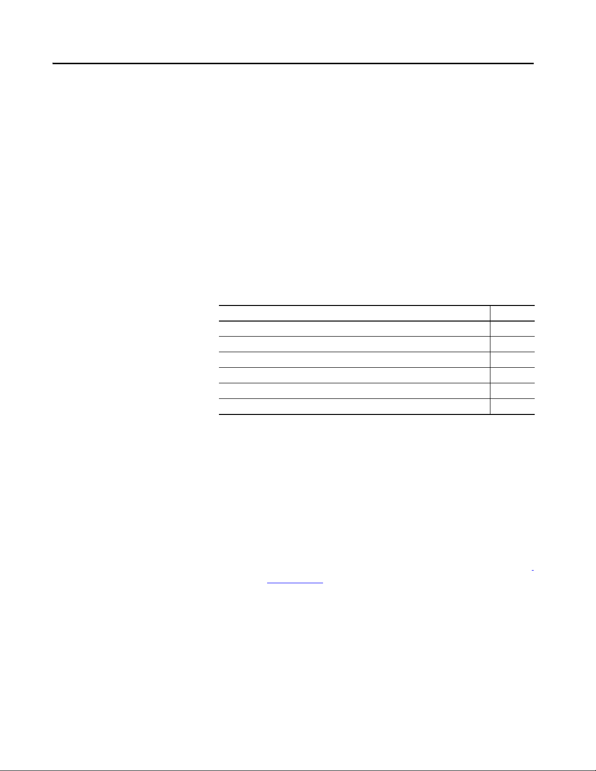
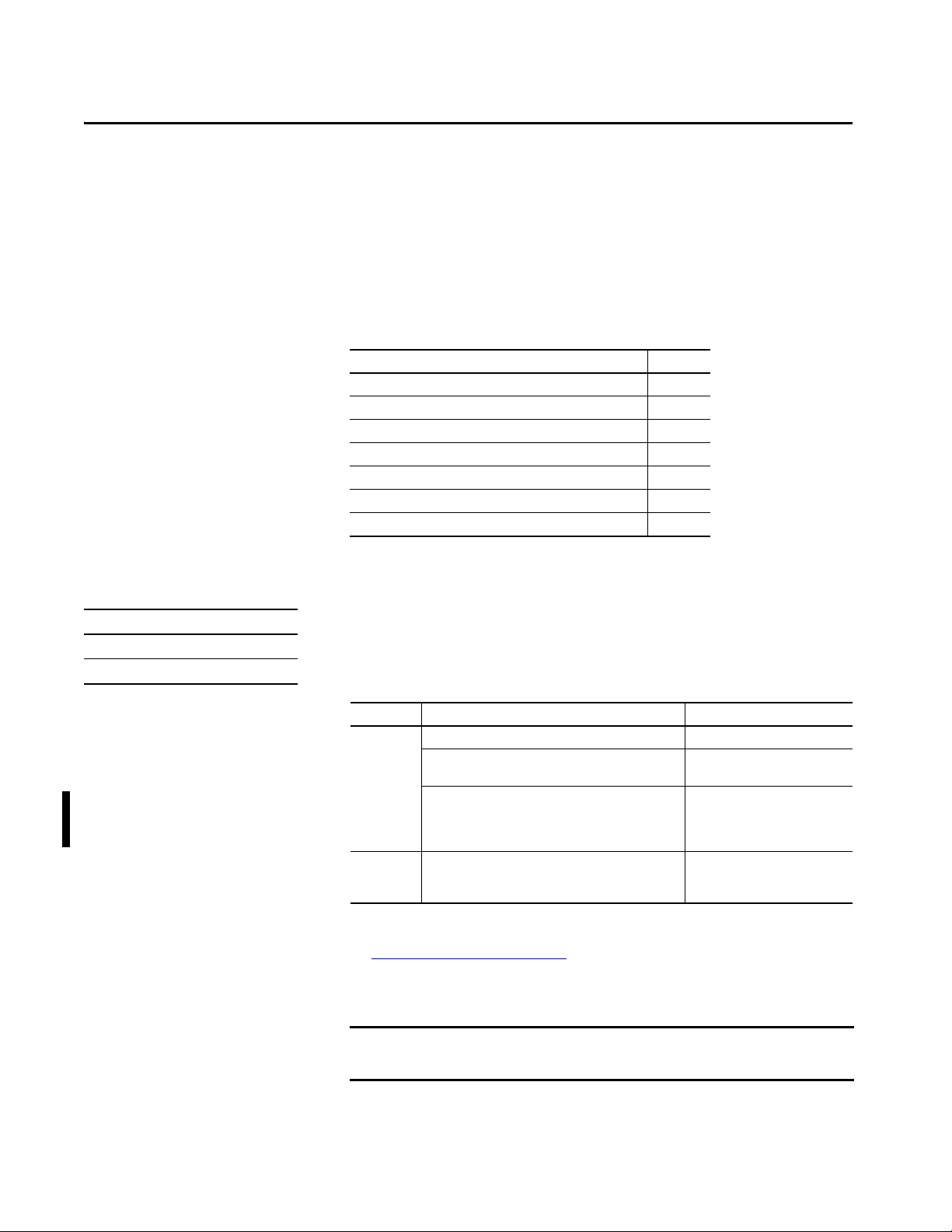
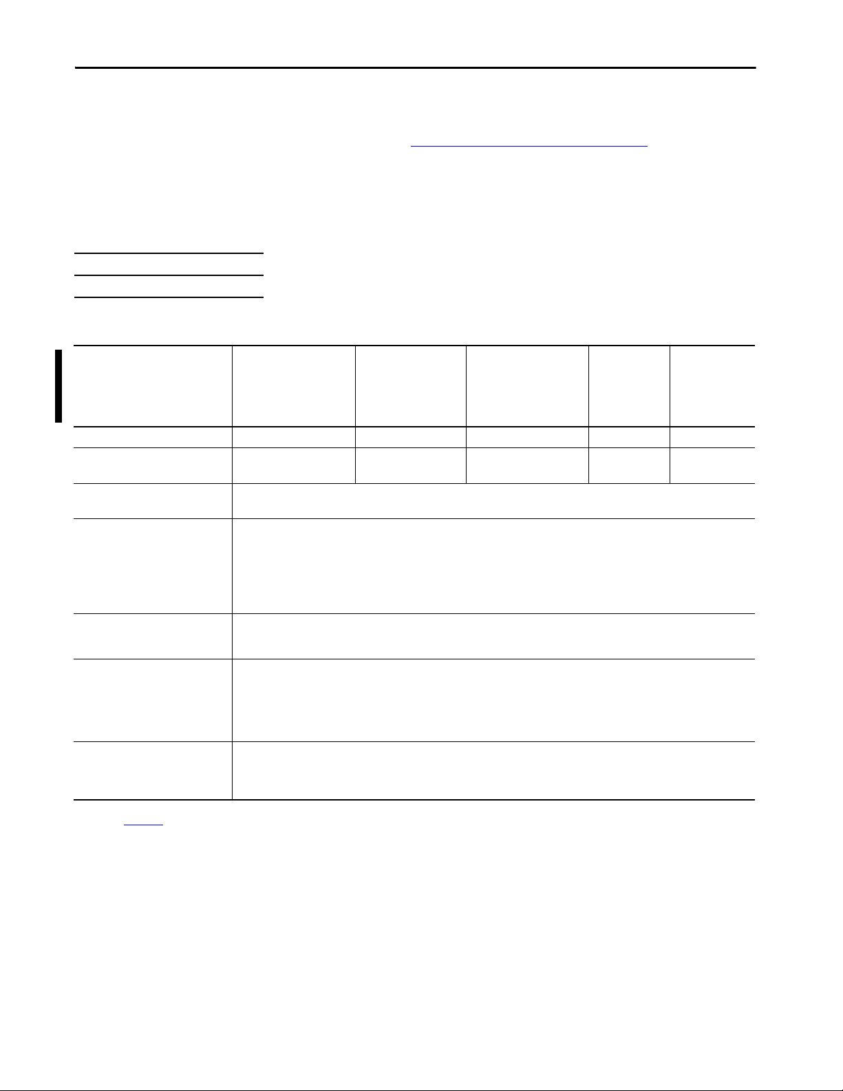
Summary of Changes
This manual contains new and updated information as indicated in the
following table.
Top ic Pag e
Added ControlLogix NSE, ControlLogix-XT, and ControlLogix Process controllers. Throughout.
Updated safety signature definition. 30
Updated behavior of controller status indicators while loading a project from the SD card. 100
Added Simple Network Management Protocol (SNMP). 109
Added Automatic Diagnostics. 249
Added Considerations for Communication Loss Diagnostics. 250
Overview
This manual provides information about designing a system, operating a
ControlLogix® or GuardLogix®-based controllers system, and developing
applications.
You must be trained and experienced in the creation, operation, and
maintenance of safety systems.
For information on Safety Integrity Level (SIL) and Performance Level (PL)
requirements and safety application requirements, see the GuardLogix 5580
and Compact GuardLogix 5380 Controller Systems Safety Reference Manual,
publication 1756-RM012.
Rockwell Automation Publication 1756-UM543K-EN-P - August 2020 11
Page 12
Preface
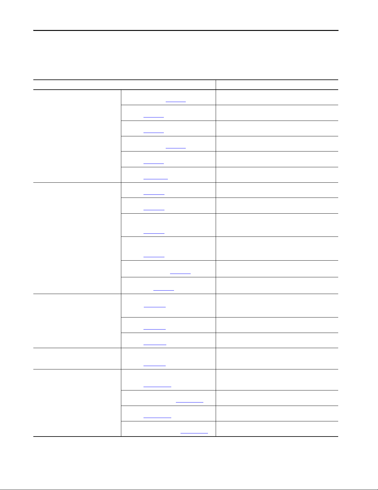
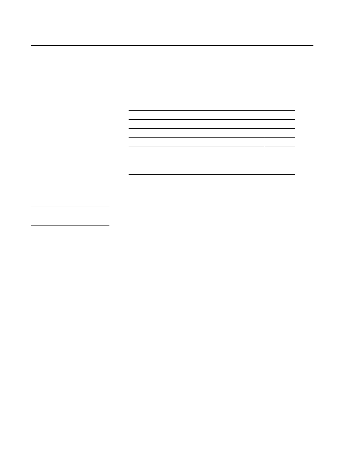
Additional Resources
These documents contain additional information concerning related products
from Rockwell Automation.
Table 1 - Additional Resources
Resource Description
Hardware Installation ControlLogix 5580 Controllers Installation
Technical Data 1756 ControlLogix Controllers Technical Data,
Networks (ControlNet, DeviceNet, EtherNet/IP) EtherNet/IP Network Devices User Manual,
Safety application requirements GuardLogix 5580 and Compact GuardLogix 5380
Motion Integrated Motion on the EtherNet/IP Network
Instructions, publication 1756-IN043
GuardLogix 5580 Controllers Installation Instructions,
publication 1756-IN048
ControlLogix Power Supply Installation Instructions,
publication 1756-IN619
ControlLogix Redundant Power Supply Installation
Instructions, publication 1756-IN620
ControlLogix Chassis Installation Instructions,
publication 1756-IN621
Replacement door labels for the 1756 I/O modules,
publication IASIMP-SP021
publication 1756-TD001
1756 ControlLogix I/O Specifications Technical Data,
publication 1756-TD002
1756 ControlLogix Communications Modules
Specifications Technical Data,
publication 1756-TD003
1756 ControlLogix Integrated Motion Modules
Specifications Technical Data,
publication 1756-TD004
1756 ControlLogix Power Supplies Specifications
Technical Data, publication 1756-TD005
1756 ControlLogix Chassis Specifications Technical
Data, publication 1756-TD006
publication ENET-UM006
ControlNet Network Configuration User Manual,
publication CNET-UM001
DeviceNet Media Design Installation Guide,
publication DNET-UM072
Controller Systems Safety Reference Manual,
publication 1756-RM012
Configuration and Startup User Manual,
publication MOTION-UM003
Integrated Motion on the EtherNet/IP Network
Reference Manual, publication MOTION-RM003
Motion Coordinate System User Manual,
publication MOTION-UM002
SERCOS and Analog Motion Configuration and
Startup User Manual, publication MOTION-UM001
Provides installation instructions for ControlLogix 5580 controllers.
Provides installation instructions for GuardLogix 5580 controllers.
Describes how to install standard power supplies.
Describes how to install redundant power supplies.
Describes how to install ControlLogix chassis.
Contains door labels for the 1756 I/O modules that are available to
print.
Provides specifications for ControlLogix controllers.
Provides specifications for ControlLogix I/O modules.
Provides specifications for ControlLogix Communications Modules.
Provides specifications for ControlLogix Integrated Motion Modules.
Provides specifications for ControlLogix Power Supplies.
Provides specifications for ControlLogix Chassis.
Describes how to configure and use EtherNet/IP™ devices with a Logix
5000™ controller and communicate with various devices on the
Ethernet network.
Provides information about ControlNet® networks.
Provides information about DeviceNet® networks.
Contains detailed requirements for achieving and maintaining
SIL 2/PLd and SIL 3/PLe with the GuardLogix 5580 controller system,
using the Studio 5000 Logix Designer® application.
Details how to design your ControlLogix system for Integrated Motion
on the EtherNet/IP network applications.
Detailed information on axis control modes and attributes for
Integrated Motion on EtherNet/IP networks.
Details how to create and configure a coordinated motion application
system.
Details how to configure a Sercos motion application system.
12 Rockwell Automation Publication 1756-UM543K-EN-P - August 2020
Page 13
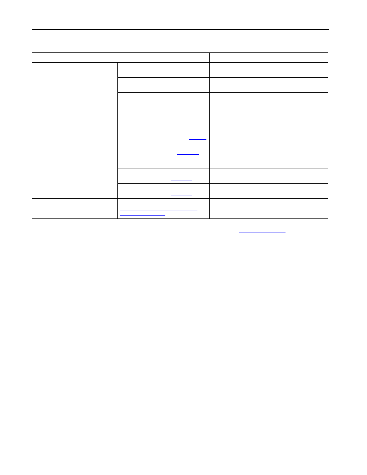
Table 1 - Additional Resources (continued)
Resource Description
Design Considerations Logix 5000 Controllers Design Considerations
Reference Manual, publication 1756-RM094
High Availability System Reference Manual,
publication HIGHAV-RM002
Ethernet Design Considerations Reference Manual,
publication ENET-RM002
FOUNDATION Fieldbus Design Considerations
Reference Manual, PROCES-RM005
Using Logix 5000 Controllers as Masters or Slaves on
Modbus Application Solution, publication CIG-AP129
Programming Tasks and Procedures Logix 5000 Controllers Common Procedures
Programming Manual, publication 1756-PM001
Logix 5000 Controllers General Instructions
Reference Manual, publication 1756-RM003
GuardLogix Safety Application Instruc tion Set
Reference Manual, publication 1756-RM095
Product Certifications Product Certifications website,
https://www.rockwellautomation.com/global/
certification/overview.page
Provides information to help design and plan Logix 5000 systems.
Provides information to help design and plan high availability
systems.
Provides additional information about network design for your
system.
This document provides design choices and best practices for
implementing a FOUNDATION Fieldbus network with the
1788-EN2FFR or 1788-CN2FFR linking devices.
For more information about using Modbus sample programs.
Provides access to the Logix 5000 Controllers set of programming
manuals. The manuals cover such topics as how to manage project
files, organize tags, program logic, test routines, handle faults, and
more.
Provides information on the programming instructions available to
use in Logix Designer application projects.
Provides information on the GuardLogix Safety application instruction
set.
Provides declarations of conformity, certificates, and other
certification details.
Preface
You can view or download publications at rok.auto/literature.
Rockwell Automation Publication 1756-UM543K-EN-P - August 2020 13
Page 14

Notes:
Preface
14 Rockwell Automation Publication 1756-UM543K-EN-P - August 2020
Page 15
Chapter 1
ControlLogix and GuardLogix Systems
This chapter describes features and functions that are associated with the
ControlLogix® 5580 and GuardLogix® 5580 controllers.
Top ic Pag e
Minimum Requirements 15
ControlLogix System 18
GuardLogix System 21
Design the System 24
CIP Security 24
Secure Controller Systems 25
ControlLogix 5580 Controller Features 25
Minimum Requirements
Applies to these controllers:
ControlLogix 5580
GuardLogix 5580
The controllers have these minimum requirements.
• ControlLogix Chassis, Series C (Series B chassis function within a
derated temperature range)
• ControlLogix Chassis Power Supply
• Programming software
System Cat. No. Studio 5000 Logix Designer®
ControlLogix 1756-L83E, 1756-L83EK
1756-L81E, 1756-L81EK, 1756-L82E, 1756-L82EK,
1756-L84E, 1756-L84EK
1756-L81E-NSE, 1756-L82E-NSE, 1756-L83E-NSE,
1756-L84E-NSE, 1756-L85E-NSE, 1756-L81EXT,
1756-L82EXT, 1756-L83EXT, 1756-L84EXT, 1756-L85EXT,
1756-L81EP, 1756-L83EP, 1756-L85EP
GuardLogix 1756-L81ES, 1756-L81ESK, 1756-L82ES, 1756-L82ESK,
1756-L83ES, 1756-L83ESK, 1756-L84ES,1756-L84ESK,
1756-L8SP, 1756-L8SPK
(1) Catalog numbers followed by a “K” indicate a conformal coating option.
(2) For compatible Linx-based communication software, and ControlFLASH Plus™ and ControlFLASH™ software, see the
Product Compatibility and Download Center (PCDC)
(3) Studio 5000 Logix Designer Professional, Full Edition, or a separately licensed GuardLogix Safety Editor must be present on the
workstation in order to edit a GuardLogix project.
(1)
, 1756-L85E, 1756-L85EK
.
Version 28.00.00 or later
Version 29.00.00 or later
Version 33.00.00 or later
Version 31.00.00 or later
(2)
(3)
IMPORTANT If safety connections or safety logic are required for your application, then
you must use a GuardLogix 5580 controller.
Rockwell Automation Publication 1756-UM543K-EN-P - August 2020 15
Page 16
Chapter 1 ControlLogix and GuardLogix Systems
ControlLogix Controllers
The controllers are available with different functionality based on your
application.
ControlLogix No Stored Energy (NSE) Controllers
The NSE controller is intended for use in applications that require the installed
controller to deplete its residual stored energy to specific levels before
transporting it into or out of your application.
The residual stored energy of the NSE controller depletes to 400μJ or less in 40
seconds.
WARNING: If your application requires the NSE controller to deplete its
residual stored energy to 400 µJ or less before you transport it into or out of
the application, complete these steps before you remove the controller.
1. Turn off power to the chassis.
After you turn off power, the controller’s OK status indicator transitions
from Green to Solid Red to OFF.
2. Wait at least 40 seconds for the residual stored energy to decrease to
400 µJ or less before you remove the controller.
There is no visual indication of when the 40 seconds has expired. You m ust
track that time period.
IMPORTANT The Real Time Clock (RTC) does not retain its time and date when the power
is off.
Some applications require that the installed controller to deplete its residual
stored energy to specific levels before transporting it into or out of your
application. This requirement can include other devices that also require a wait
time before removing them. See the documentation of those products for more
information.
ControlLogix-XT Controllers
The ControlLogix-XT ™ (Extended Temperature) controllers function in the
same way as the traditional ControlLogix controllers, with an extended
temperature range, and have the same features as the ControlLogix standard
controllers.
The ControlLogix-XT controllers are conformal coated to add a layer of
protection when exposed to harsh, corrosive environments. While the standard
ControlLogix system can withstand temperatures from 0…60 °C (33…140 °F),
the ControlLogix-XT system can withstand temperatures from -25…+70 °C
(-13…+158 °F).
16 Rockwell Automation Publication 1756-UM543K-EN-P - August 2020
Page 17
ControlLogix and GuardLogix Systems Chapter 1
Process Controllers
The process controller is an extension of the Logix 5000 controller family that
focuses on plantwide process control. The process controller comes configured
with a default process tasking model and dedicated PlantPAx process
instructions optimized for process applications and that improve design and
deployment efforts.
The ControlLogix process controller hardware is also conformal coated to add
a layer of protection when exposed to harsh, corrosive environments, and can
be used in temperature extremes from -25…+70 °C (-13…+158 °F) when
deployed as part of a Logix-XT system.
Conformal Coated Products
ATT EN TI ON : Conformal coated products are shipped with port protection
plugs installed to provide a layer of protection from corrosive environments.
In order to meet the corrosive atmosphere rating of the product, port plugs
need to be installed in unused ports at all times during storage and
operation. If temporary access is required, plugs can be removed, and should
be reinserted after temporary access is complete.
ControlLogix Redundant Controllers
You can use ControlLogix 5580 controllers in redundant applications with the
Studio 5000 Logix Designer application, version 33.00.00 or later.
For information, see these publications:
• High Availability System Reference Manual, publication
HIGHAV-RM002
• ControlLogix 5580 Redundant Controller User Manual, publication
1756-UM015
Rockwell Automation Publication 1756-UM543K-EN-P - August 2020 17
Page 18
Chapter 1 ControlLogix and GuardLogix Systems
ControlLogix System
Applies to these controllers:
ControlLogix 5580
The ControlLogix system is chassis-based, which provides options for
configuring a variety of communications and I/O capabilities. The
ControlLogix controllers support multiple programming languages that enable
sequential, process, motion, and drive control.
A variety of system configuration options are described in the following
sections.
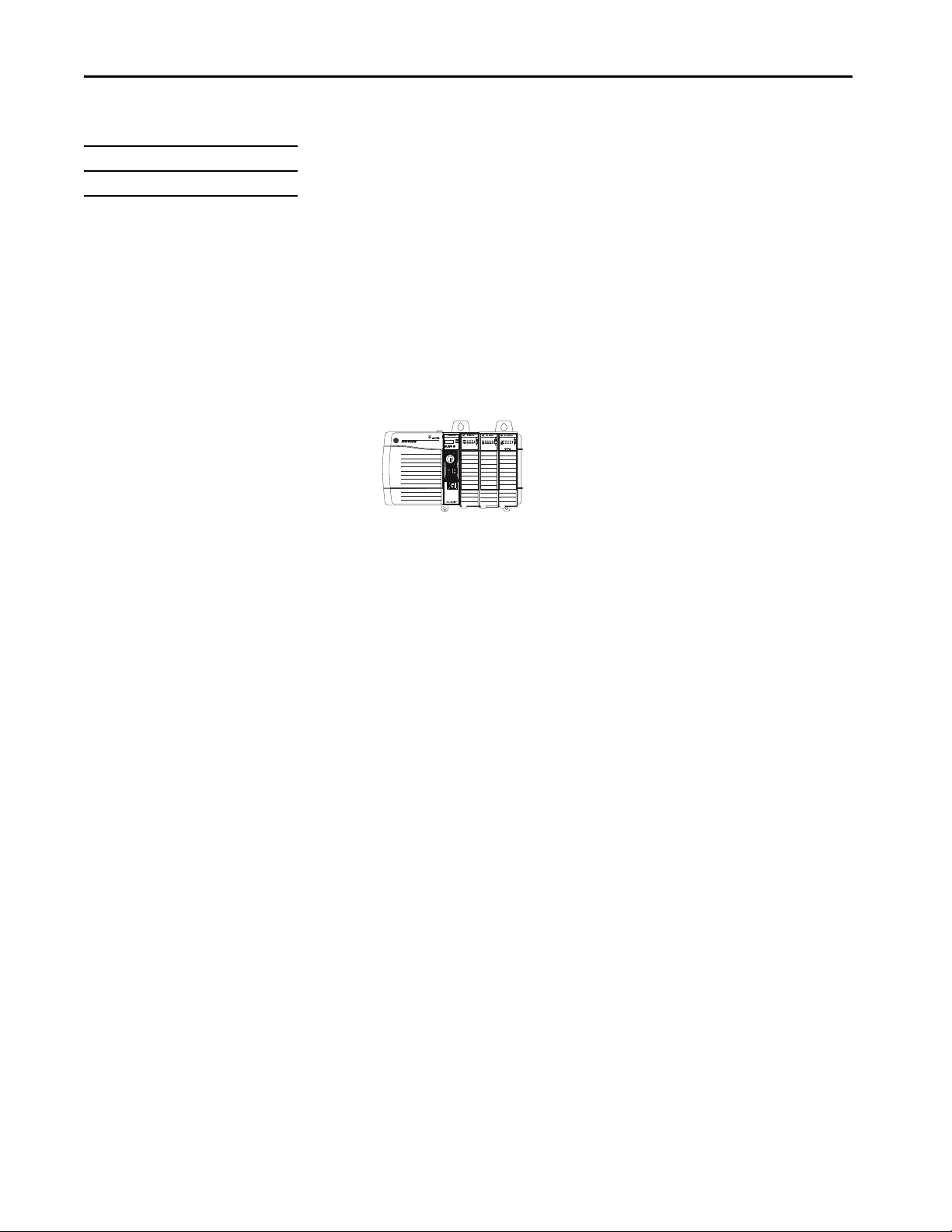
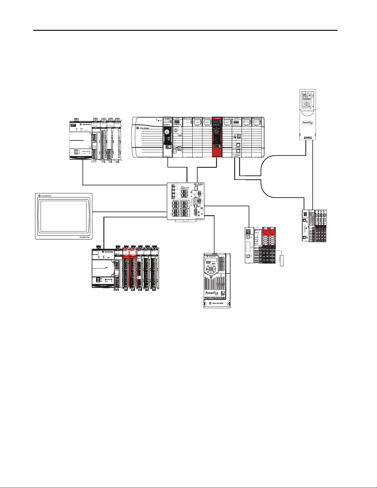
Standalone Controller and I/O
One of the simplest controller configurations is a standalone controller with
I/O assembled in one chassis.
Figure 1 - Standalone Controller and I/O
18 Rockwell Automation Publication 1756-UM543K-EN-P - August 2020
Page 19
ControlLogix and GuardLogix Systems Chapter 1
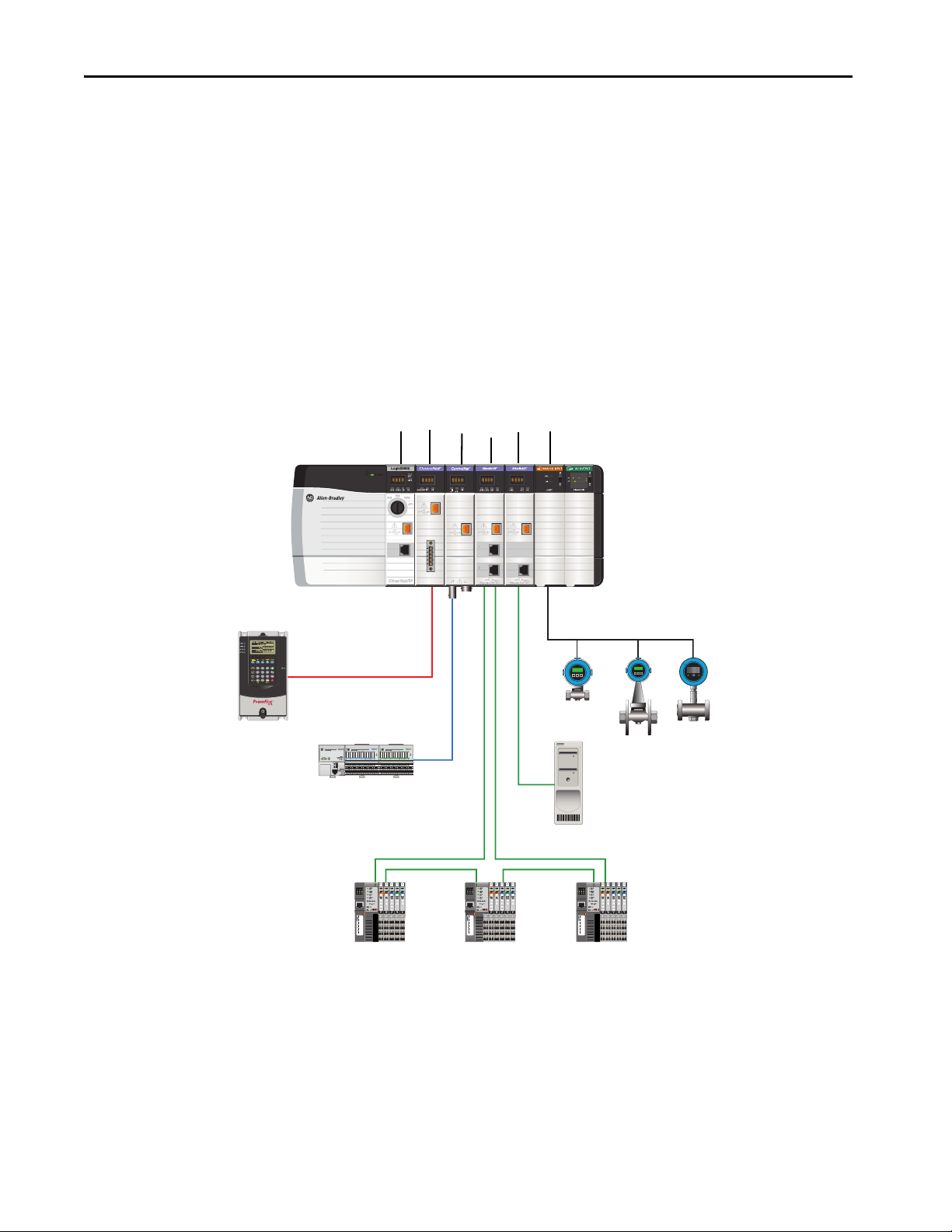
Panel View™ Pl us 7
Stratix® 5400
5069-AEN2TR
Compact 5000 Safety I/O Modules
Compact 5000 I/O Modules
PowerFlex® 755 Drive
1 Gbps
1 Gbps
100 Mbps
100 Mbps
1734-AENTR
1734 POINT I/O™
100 Mbps
1734-AENTR EtherNet/IP Adapter
1734 POINT Guard I/O™
Safety Device
1 Gbps
PowerFlex 527 Drive
(CIP Safety™ enabled)
100 Mbps
1 Gbps
5069-AEN2TR
Compact 5000™ I/O modules
1756-EN2TR
1756-L84ES
1756-L85E
1756-L72
Multiple Controllers in One Chassis
You can use multiple controllers in one ControlLogix chassis. This example
shows a ControlLogix 5580 controller (slot 0) connected directly to the
EtherNet/IP™ network, a ControlLogix 5570 controller (slot 1) connected to
the network through a 1756-EN2TR module (slot 7), and a GuardLogix 5580
controller in a SIL 2/PLd configuration (slot 5) connected directly to the
EtherNet/IP Network.
Figure 2 - Multiple Controllers in One Chassis
IMPORTANT You cannot bridge through the Ethernet (front) port of another controller to
add remote I/O.
Rockwell Automation Publication 1756-UM543K-EN-P - August 2020 19
Page 20
Chapter 1 ControlLogix and GuardLogix Systems
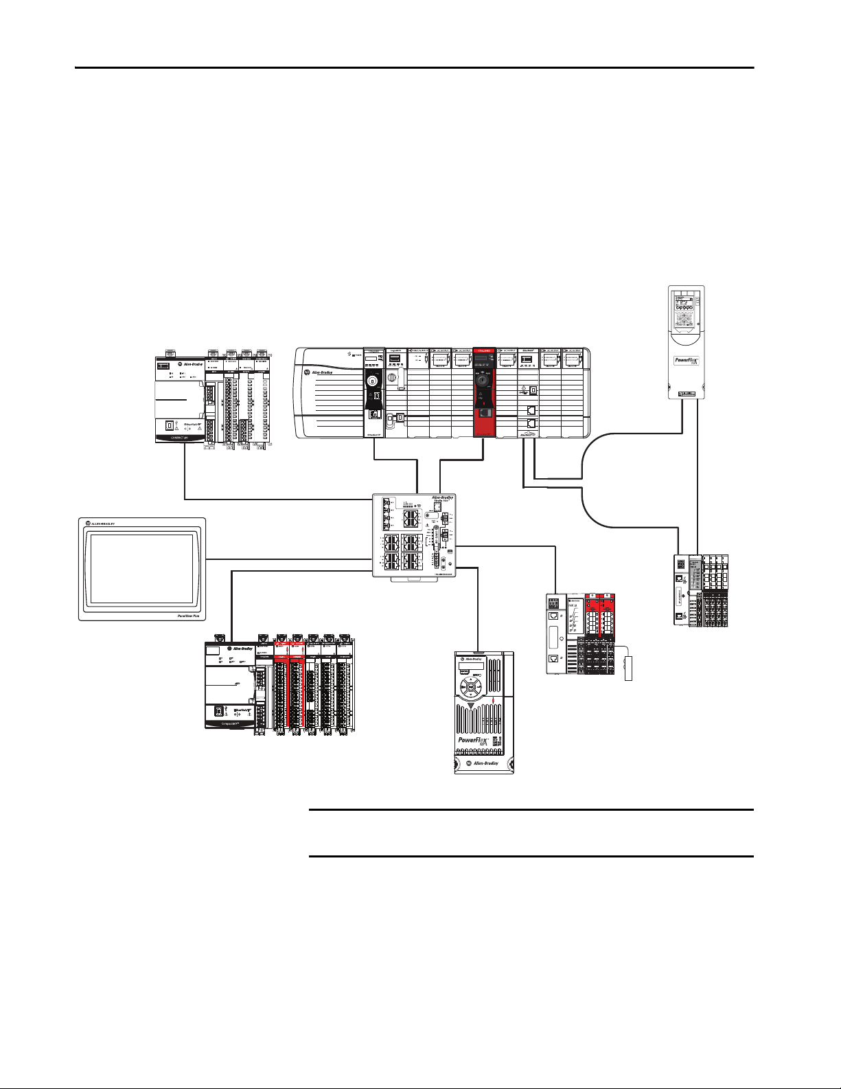
PowerFlex Drive
DeviceNet
FLEX™ I/O
Control Net
Ethernet Device-level
Ring Network
Ethernet
HART
Endress + Hauser Flowmeters
Fac toryTa lk® Ser ver
POINT I/O
1756-L85E
1756-DNB
1756-CN2R
1756-EN2TR
1756-EN2T
1756-IF8H
Multiple Devices Connected via Multiple Networks
For some applications, various devices can be connected to the ControlLogix
chassis via multiple communication networks. For example, a system can be
connected to the following:
• Distributed I/O via an Ethernet network
• A PowerFlex drive connected via a DeviceNet® network
• Distributed I/O via a ControlNet® network.
• Flowmeters that are connected via a HART connection
Figure 3 - Multiple Devices Connected Via Multiple Networks
20 Rockwell Automation Publication 1756-UM543K-EN-P - August 2020
Page 21

ControlLogix and GuardLogix Systems Chapter 1
GuardLogix System
Applies to these controllers:
GuardLogix 5580
The GuardLogix system can communicate with safety I/O devices via
CIP Safety over an EtherNet/IP network (Guard I/O™ modules, integrated
safety drives, integrated safety components).
For a GuardLogix controller, you can interface to local standard I/O in the
backplane via standard tasks while you interface with remote safety I/O
through the EtherNet/IP port.
The GuardLogix system supports up to SIL 3 and PLe safety applications.
• Without a safety partner installed, you can achieve SIL 2/PLd
(Category 3) with the use of the safety task and safety I/O.
• With the use of the safety task and a safety partner installed, you can
achieve SIL 3/PLe (Category 4) capability.
IMPORTANT For the safety task, GuardLogix controllers support Ladder Diagram only.
For standard tasks, GuardLogix controllers support:
• Ladder Diagram (LD)
• Structured Text (ST)
• Function Block Diagram (FBD)
• Sequential Function Chart (SFC)
For SIL 3 safety applications, the GuardLogix system is composed of a primary
GuardLogix controller and a safety partner that function together in a 1oo2
architecture.
• The primary controller is the processor that performs standard and
safety functions and communicates with the safety partner for safetyrelated functions in the GuardLogix control system.
• The safety partner is a co-processor that provides an isolated second
channel for safety-related functions in the system. The safety partner
does not have a key switch or communication port. The primary
controller controls the configuration and operation of the safety partner.
• The safety partner must be installed in the slot immediately to the right
of the primary controller. The firmware major and minor revisions of
the primary controller and safety partner must match exactly to establish
the control partnership that is required for safety applications
For information on Safety Integrity Level (SIL) and Performance Level (PL)
requirements and safety application requirements, see the GuardLogix 5580
and Compact GuardLogix 5380 Controller Systems Safety Reference Manual,
publication 1756-RM012
.
Rockwell Automation Publication 1756-UM543K-EN-P - August 2020 21
Page 22
Chapter 1 ControlLogix and GuardLogix Systems
MOD
NET
MOD
NET
MOD
NET
MOD
NET
2
1
1
1
4
I/O
I/O
6
5
10
2
1
2
1
2
1
1
I/O-A
6
510
1
I/O-B
6
510
1
I/O-A61I/O-B
6
510510
UFB
UFB-A UFB-B
UFB-A UFB-B
D+D-D+
D-
D+
D-
MF-A MF-B MF-A MF-B
D+
D-
MBRK
+
-
5069-IB8S
5069-OBV8S
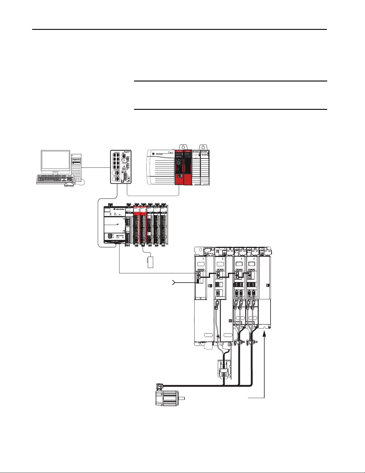
GuardLogix 5580 Safety Controller
GuardLogix 1756-L8SP Safety Partner
Studio 5000 Logix Designer
Application
(version 31.00 or later)
Kinetix® 5700 Servo Drive System
Digital Inputs to Sensors and Control String
Kinetix VP
Servo Motors
2198-CAPMOD-2240
Capacitor Module
(optional component)
1783-BMS
Stratix 5700 Switch
Module Definition
Configured with
Motion and Safety
Conne ction
5069-AEN2TR
Compact 5000 Safety I/O modules
Compact 5000 I/O modules
Safety Device
GuardLogix with Safety I/O and Integrated Safety Drives
In this example, a single GuardLogix safety controller makes the Motion and
Safety connections.
IMPORTANT If only one controller is used in an application with Motion and Safety
connections, it must be a safety controller such as the GuardLogix 5580
controller.
Figure 4 - Motion and Safety Configuration (single controller)
22 Rockwell Automation Publication 1756-UM543K-EN-P - August 2020
Page 23
ControlLogix and GuardLogix Systems Chapter 1
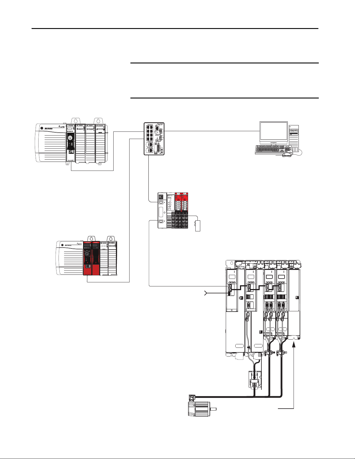
GuardLogix 5580 Safety Controller
GuardLogix 1756-L8SP Safety Partner
Studio 5000 Logix Designer
Application
(version 31.00 or later)
Kinetix 5700 Servo Drive System
Digital Inputs to Sensors and Control String
Kinetix VP
Servo Motors
2198-CAPMOD-2240
Capacitor Module
(optional component)
1734-AENTR
POINT Guard I/O
EtherNet/IP Adapter
1783-BMS
Stratix 5700
Switch
ControlLogix 5580 Controller
Motion Program
Module Definition Configured with
Motion only Connection
Safety Program
Module Definition Configured
with Safety only Connection
Safety
Device
In this example, a standard controller makes the Motion-only connection and a
separate GuardLogix 5580 controller makes the safety-only connection.
IMPORTANT If two controllers are used in an application with motion-only and safety-
only connections, the safety-only connection must be a GuardLogix
controller while the motion-only connection can be made by either a
standard or a safety controller.
Figure 5 - Motion and Safety Configuration (multi-controller)
MOD
MOD
NET
2
1
1
4
I/O
MOD
NET
2
1
I/O
1
6
5
10
UFB
D-
-
MBRK
+
NET
2
2
1
1
I/O-A
I/O-B
1
6
1
6
1
510
510
510510
UFB-A UFB-B
D+D-D+
D+
D-
MF-A MF-B MF-A MF-B
I/O-A61I/O-B
UFB-A UFB-B
MOD
NET
6
D+
D-
Rockwell Automation Publication 1756-UM543K-EN-P - August 2020 23
Page 24

Chapter 1 ControlLogix and GuardLogix Systems
Design the System
Applies to these controllers:
ControlLogix 5580
GuardLogix 5580
When you design a a system, there are several system components to consider
for your application:
• I/O devices
• Motion control axes and drives
• Communication modules
•Controllers
• Chassis
•Power supplies
• Studio 5000 Logix Designer Application
In addition, safety systems have also have components to consider:
•Safety Controller
• Safety Partner (for SIL 3/PLe applications)
•Safety I/O
•Safety Devices
For more information to design and select components for your system, see:
• 1756 ControlLogix Controllers Technical Data,
publication 1756-TD001
• 1756 ControlLogix I/O Specifications Technical Data,
publication 1756-TD002
• GuardLogix 5580 and Compact GuardLogix 5380 Controller Systems
Safety Reference Manual,
publication 1756-RM012
CIP Security
CIP Security™ is a standard, open-source communication method that helps to
provide a secure data transport across an EtherNet/IP network.
The secure data transport is used between certain connected devices to help
protect the devices from threats posed by unauthorized users with malicious
intent.
Rockwell Automation uses the following products to implement CIP Security:
• FactoryTalk Policy Manager
•FactoryTalk Linx
• Studio 5000® Design Environment
• CIP Security-enabled products from Rockwell Automation, for
example, the products described in this publication
For more information on CIP Security, including which products support CIP
Security, see the CIP Security Application Technique, publication SECURE-
AT001.
24 Rockwell Automation Publication 1756-UM543K-EN-P - August 2020
Page 25
ControlLogix and GuardLogix Systems Chapter 1
Secure Controller Systems
The ControlLogix 5580 controller, firmware revision 32 supports
IEC-62443-4-2 SL 1 requirements. For security features and system
requirements, see Develop Secure Applications
ControlLogix 5580 Controller Features
Applies to these controllers:
ControlLogix 5580
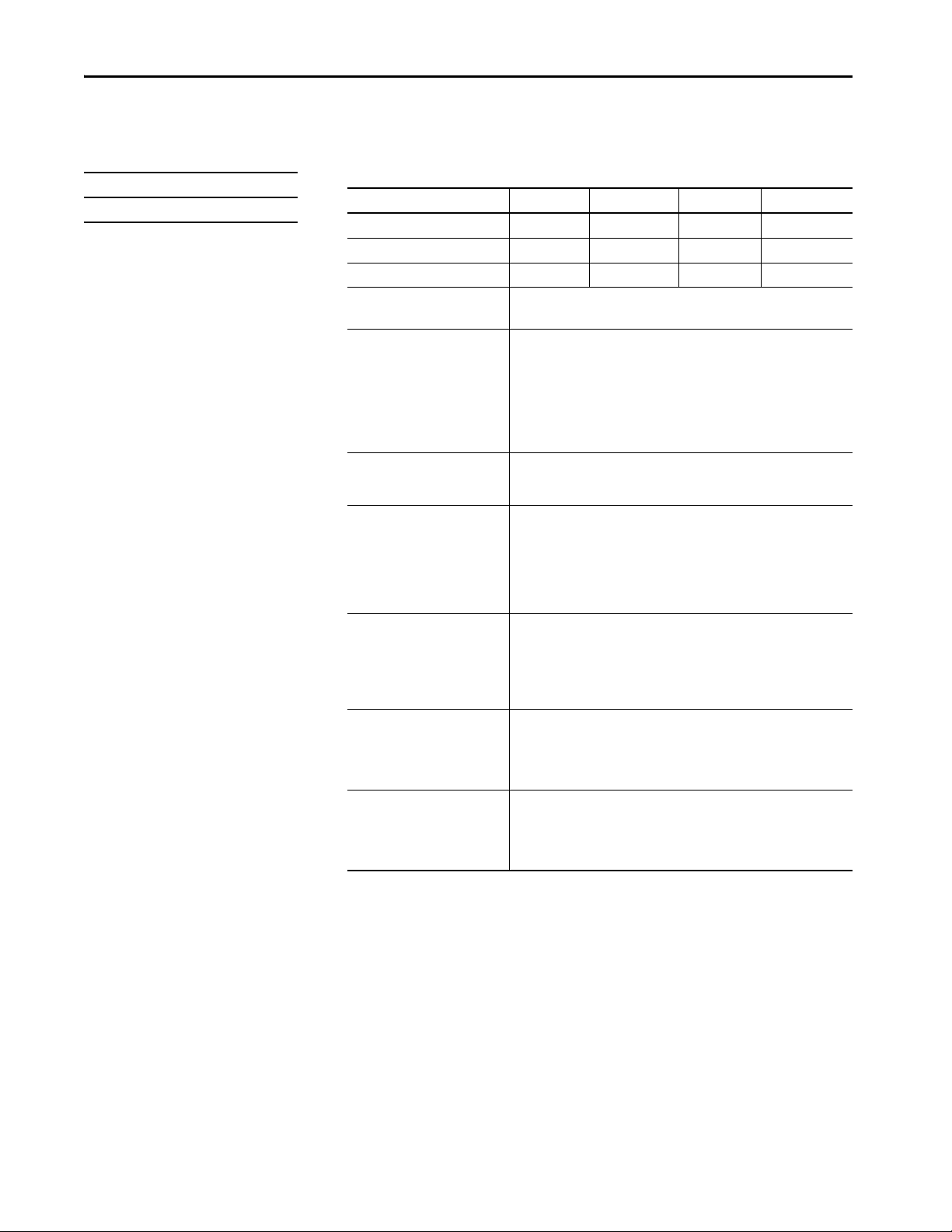
Table 1 - ControlLogix 5580 Controller Features
Feature 1756-L81E, 1756-L81EK,
1756-L81E-NSE,
1756-L81EXT, 1756-L81EP
User Memory 3 MB 5 MB 10 MB 20 MB 40 MB
60 nodes
EtherNet/IP nodes supported, max
Communication ports 1 - USB port, 2.0 full-speed, Type B
Communication options • EtherNet/IP
Controller tasks • 32 tasks
Integrated motion • Integrated Motion on the EtherNet/IP network
Programming languages • Ladder Diagram (LD)
(1) A node is an EtherNet/IP device that you add directly to the I/O configuration, and counts toward the node limits of t he controller. For more information on EtherNet/IP nodes, see the ControlLogix 5580 Controllers User Manual,
publication1756-UM543
(2) With Studio 5000 Logix Designer Application Version 31 or greater.
(3) With Studio 5000 Logix Designer Application Version 28 and Version 29.
(4) With Studio 5000 Logix Designer Application Version 29.
(5) With Studio 5000 Logix Designer Application Version 30 or greater.
(6) With Studio 5000 Logix Designer Application Version 28 or greater.
.
(1)
100 nodes
1 - EtherNet/IP port: 10 Mbps, 100 Mbps, 1 Gbps link speeds
•ControlNet
• DeviceNet
• Data Highway Plus™
• Remote I/O
•SynchLink™
• Third-party process and device networks
• 1000 programs/task
• Event tasks: all event triggers
• Sercos interface
• Analog options
–Encoder input
– Linear displacement transducer (LDT) input
– Serial Synchronous Input (SSI)
• Structured Text (ST)
• Function Block Diagram (FBD)
• Sequential Function Chart (SFC)
This table lists the system, communication, and programming features
available with ControlLogix 5580 controllers.
1756-L82E, 1756L82EK, 1756-L82E-NSE,
1756-L82EXT
(4)
(5)
(2)
(2)
:
80 nodes
175 nodes
(4)
(5)
1756-L83E, 1756-L83EK,
1756-L83E-NSE,
1756-L83EXT, 1756-L83EP
(3)
100 nodes
(5)
250 nodes
on page 207.
1756-L84E,
1756-L84EK,
1756-L84E-NSE,
1756-L84EXT
(4)
150 nodes
(5)
250 nodes
1756-L85E,
1756-L85EK,
1756-L85E-NSE,
1756-L85EXT,
1756-L85EP
(6)
300 nodes
Rockwell Automation Publication 1756-UM543K-EN-P - August 2020 25
Page 26
Chapter 1 ControlLogix and GuardLogix Systems
GuardLogix 5580 Controller Features
Applies to these controllers:
GuardLogix 5580
This table lists the system, communication, and programming features
available with GuardLogix 5580 controllers.
Table 2 - GuardLogix 5580 Controller Features
Feature 1756-L81ES 1756-L82ES 1756-L83ES 1756-L84ES
User Memory 3 MB 5 MB 10 MB 20 MB
Safety Memory 1.5 MB 2.5 MB 5 MB 6 MB
EtherNet/IP nodes supported, max 100 175 250 250
Communication ports 1 - USB port, 2.0 full-speed, Type B
1 - EtherNet/IP port: 10 Mbps, 100 Mbps, 1 Gbps link speeds
Communication options • EtherNet/IP (1756-EWEB cannot be used for safety connections)
• Support for Network address translation (NAT)
• ControlNet
• DeviceNet
• Data Highway Plus
• Remote I/O
•SynchLink
• Third-party process and device networks
Controller tasks • 31 standard tasks, 1 safety task
• 1000 programs/task
• Event tasks: all event triggers
Integrated motion Integrated motion is supported in standard task only.
• Integrated Motion on the EtherNet/IP network
• Sercos interface
•Analog options:
– Encoder input
– Linear displacement transducer (LDT) input
– Serial Synchronous Input (SSI)
Programming languages • For the safety task, GuardLogix controllers support Ladder Diagram only.
• For standard tasks, GuardLogix controllers support:
– Ladder Diagram (LD)
– Structured Text (ST)
– Function Block Diagram (FBD)
– Sequential Function Chart (SFC)
Integrated safety • Integrated safety on the EtherNet/IP network (Kinetix drives, PowerFlex
drives, safety components)
• Distribute and control safety I/O (over EtherNet/IP and DeviceNet networks
only)
• Produce and consume safety tag data.
Controller Features • Data access control
• Firmware supervisor
• Secure Digital (SD) card
• Safety Connections
• Standard Connections
26 Rockwell Automation Publication 1756-UM543K-EN-P - August 2020
Page 27

ControlLogix and GuardLogix Systems Chapter 1
Features Supported By GuardLogix 5580 Controllers Via the Safety Task
In the Logix Designer application, version 31 or later, the Safety task supports a
subset of features that are supported in the standard task as listed in this table.
Feature Studio 5000 Logix Designer Application,
Safety Task Standard Task
Add-on instructions X X
Instruction-based alarms and events — X
Tag-based alarms — X
Controller logging X X
Event task s
Function block diagrams (FBD) — X
Integrated motion X
Analog motion — X
Sercos motion — X
Drive Safety Instructions X —
Ladder Diagram (LD) X X
Language switching X X
License-based source protection — X
Online import of program components — X
Online export of program components X X
Sequential function chart (SFC) routines — X
Structured Text (ST) — X
(1) While the safety task cannot be an Event task, standard Event tasks can be triggered with the use of the Event instruction in the
(2) Limited to the use of Drive Safety Instructions wi th Kinetix 5700 ERS4 drives.
(1)
safety task.
Version 31 or Later
—X
(2)
X
IM PORTANT Safety Consideration
GuardLogix 5580 controllers can produce standard tags as unicast or multicast, but they can only
produce safety tags as unicast. The controllers can consume safety tags as either unicast or multicast.
When you configure a produced safety tag, you are only allowed to configure unicast connection
options. Logix Designer does not allow you to configure multicast connection options.
When you configure a consumed tag, you must consider the capabilities of the producer:
• If the producer in the I/O tree of this controller is a GuardLogix 5580 or Compact GuardLogix 5380
controller, and you are consuming a safety tag, you must configure the consumed tag to use unicast.
• If the producer in the I/O tree of this controller is a GuardLogix 5570 or 5560, or a Compact
GuardLogix 5370, the safety consumed tag can be configured as either unicast or multicast.
• GuardLogix 5580 controllers do not produce safety tags to GuardLogix 5570 (firmware revision 30
and earlier) controllers in the same chassis, because GuardLogix 5580 controllers can only produce
safety tags as unicast, and GuardLogix 5570 (firmware revision30 and earlier) controllers cannot
configure consumed tags as unicast. This restriction does not apply over EtherNet/IP, as consumed
tags can be configured for unicast.
Rockwell Automation Publication 1756-UM543K-EN-P - August 2020 27
Page 28

Chapter 1 ControlLogix and GuardLogix Systems
Notes:
28 Rockwell Automation Publication 1756-UM543K-EN-P - August 2020
Page 29
Chapter 2
Safety Concept of GuardLogix Controllers
Top ic Pag e
Functional Safety Capability 29
Safety Network Number 30
Safety Signature 30
Distinguish between Standard and Safety Components 31
Controller Data-flow Capabilities 32
Safety Terminology 33
Functional Safety Capability
Applies to these controllers:
GuardLogix 5580
The GuardLogix® 5580 controller system is certified for use in safety
applications up to and including SIL 2/PLd and SIL 3/PLe where the
de-energized state is the safe state.
For SIL 3/PLe safety applications, the GuardLogix system is made up of a
primary controller and a safety partner, that function together in a 1oo2
architecture.
For SIL 2/PLd and SIL 3/PLe safety system requirements, including
functional validation test intervals, system reaction time, and PFD/PFH
calculations, see the GuardLogix 5580 and Compact GuardLogix 5380
Controller Systems Safety Reference Manual, publication 1756-RM012
.
You must read, understand, and fulfill these requirements before you operate a
GuardLogix SIL 2/PLd or SIL 3/PLe safety system.
Rockwell Automation Publication 1756-UM543K-EN-P - August 2020 29
Page 30

Chapter 2 Safety Concept of GuardLogix Controllers
Safety Network Number
The safety network number (SNN) uniquely identifies CIP Safety™ subnets
within a routable safety network. The combination of the SNN + Node
Address uniquely identifies each CIP Safety port on each device in the routable
safety network.
The GuardLogix 5580 controllers require two safety network numbers: one
for the Ethernet port, and one for the backplane.
Safety Signature
For an explanation of the Safety Network Number, see the GuardLogix 5580
and Compact GuardLogix 5380 Controller Systems Safety Reference Manual,
publication 1756-RM012.
For information on how to assign the SNN, see Assign the Safety Network
Number (SNN) on page 65.
The safety signature is composed of a safety signature ID (identification
number), and a timestamp (date and time). The safety signature ID applies to
the entire safety portion of the controller and uniquely identifies each project,
including its logic, data, and configuration.
The GuardLogix system uses the safety signature to determine project integrity
and to let you verify that the correct project is downloaded to the target
controller. The ability to create, record, and verify the safety signature is a
mandatory part of the safety-application development process.
The safety signature must be present to operate as a SIL 2/PLd or SIL 3/PLe
safety controller.
See Generate a Safety Signature
on page 192 for more information.
30 Rockwell Automation Publication 1756-UM543K-EN-P - August 2020
Page 31

Safety Concept of GuardLogix Controllers Chapter 2
Distinguish between Standard and Safety Components
Slots of a GuardLogix system chassis that are not used by the safety function
can be populated with other ControlLogix® modules that are certified to the
Low Voltage and EMC Directives. See the Rockwell Automation Product
Certifications page (
certification/overview.page?)
Product Family, and determine the modules that are certified.
You must create and document a clear, logical, and visible distinction between
the safety and standard portions of the controller project. As part of this
distinction, the Studio 5000 Logix Designer® application features safety
identification icons to identify the safety task, safety programs, safety routines,
and safety components.
In addition, the Logix Designer application uses a safety class attribute that is
visible whenever safety task, safety programs, safety routine, safety tag, or safety
Add-On Instruction properties are displayed.
http://www.rockwellautomation.com/global/
to find the CE certificate for the ControlLogix
Rockwell Automation Publication 1756-UM543K-EN-P - August 2020 31
Page 32

Chapter 2 Safety Concept of GuardLogix Controllers
GuardLogix Controller
Controller Data-flow Capabilities
This illustration explains the standard and safety data-flow capabilities of the
GuardLogix controller.
Figure 6 - Data-flow Capabilities
Standard Safety
Standard Tasks
Standard Programs
Standard Routines
Program Data
Controller Standard Tags
Safety Task
Safety Programs
Safety Routines
Program Safety Data
Controller Safety Tags
No. Description
1 Standard tags and logic behave the same way that they do in a standard ControlLogix controller.
2 Standard tag data, program- or controller-scoped, can be exchanged with external HMI devices,
personal computers, and other controllers.
3 GuardLogix controllers are integrated controllers with the ability to move (map) standard tag data into
safety tags for use within the safety task. This is the only way to get standard tag data in to the safety
task. Safety logic in the safety task cannot read or write the standard tag that is the source in the tag
mapping data transfer; it can only reference the safety tag destination of the mapping. But, it can read
and write that safety tag.
ATT EN TI ON : Mapped tag data must not be used to control a SIL 2/PLd or
SIL 3/PLe output directly.
4 Controller-scoped safety tags can be read directly by standard logic.
5 Safety tags can be read or written by safety logic.
6 Safety tags can be exchanged between safety controllers over Ethernet or ControlNet® networks,
including 1756 and 5069 GuardLogix controllers.
7 Safety tag data, program- or controller-scoped, c an be read by external devices, such as HMI devices,
personal computers, or other standard controllers. External devices cannot write to safety tags
(whether the controller is protected or not).
Once this data is read, it is considered standard data, not SIL 3/PLe data.
32 Rockwell Automation Publication 1756-UM543K-EN-P - August 2020
Page 33

Safety Concept of GuardLogix Controllers Chapter 2
Safety Terminology
This table defines safety terms that are used in this manual.
Table 3 - Safety Terms and Definitions
Abbreviation Full Term Definition
1oo1 One Out of One Identifies the programmable electronic controller architecture. 1oo1 is a single-channel system.
1oo2 One Out of Two Identifies the programmable electronic controller architecture. 1oo2 is a dual-channel system.
CIP Safety Common Industrial Protocol – Safety Certified SIL 3/PLe-rated version of CIP™.
DC Diagnostic Coverage The ratio of the detected failure rate to the total failure rate.
PFD Probability of Failure on Demand The average probability of a system to fail to per form its design function on demand.
PFH Probability of Failure per Hour The probability of a system to have a dangerous failure occur per hour.
PL Performance Level ISO 13849-1 safety rating.
SIL Safety Integrity Level A relative level of risk-reduction provided by a safety function, or to specify a target level of risk reduction .
SIL CL SIL Claim Limit The maximum safety integrity level (SIL) that can be achieved.
SNN Safety Network Number A unique number that identifies a section of a safety network.
UNID Unique Node ID (also called unique node
referenc e)
The unique node reference is a combination of a safe ty network number (SNN) and the node address of the
node.
Rockwell Automation Publication 1756-UM543K-EN-P - August 2020 33
Page 34

Chapter 2 Safety Concept of GuardLogix Controllers
Notes:
34 Rockwell Automation Publication 1756-UM543K-EN-P - August 2020
Page 35

Communication Networks
Several communication networks are available.
Top ic Pag e
Networks Available 35
EtherNet/IP Network Communication 37
Double Data Rate (DDR) Backplane Communication for ControlLogix
Control lers
ControlNet Network Communication 41
DeviceNet Network Communication 44
Data Highway Plus (DH+) Network Communication 45
Universal Remote I/O (RIO) Communication 47
Foundation Fieldbus Communication 49
HART Communication 50
Chapter 3
40
Networks Available
Ta b l e 4 describes typical application features that are used with ControlLogix®
and GuardLogix® systems, and lists the networks available to support such
application features.
Table 4 - Applications and Supported Networks
Application Features ControlLogix and GuardLogix Supported
Integrated Motion
Time synchronization EtherNet/IP EtherNet/IP
Control of distributed I/O • EtherNet/IP
Produce/consume data between controllers • EtherNet/IP
Messaging to and from other devices, including access to
the controller via the Studio 5000 Logix Designer®
application
(1) The controllers also support analog and Sercos motion interfaces. For more information, See Develop Motion Applications on page 243.
(1)
Networks for Standard Communications
EtherNet/IP™ EtherNet/IP
• DeviceNet®
• ControlNet®
• Foundation Fieldbus
•HART
• Universal remote I/O
•ControlNet
• EtherNet/IP
•ControlNet
• DeviceNet (only to devices)
• Data Highway Plus™ (DH+™)
• DH-485
GuardLogix Supported Networks for
CIP Safety™ Communications
Time synchronization does not use the safety protocol.
•EtherNet/IP
•ControlNet
Messaging does not use the safety protocol.
Rockwell Automation Publication 1756-UM543K-EN-P - August 2020 35
Page 36

Chapter 3 Communication Networks
For more information about using EtherNet/IP modules, see these
publications:
• EtherNet/IP Modules in Logix 5000 Control Systems User Manual,
publication ENET-UM001
• EtherNet/IP Communication Modules in 5000 Series Systems,
publication ENET-UM004
For more information about network design, see these publications;
• Ethernet Design Considerations Reference Manual,
publication ENET-RM002
.
• ControlNet Network Configuration User Manual,
publication CNET-UM001
• DeviceNet Media Design Installation Guide,
publication DNET-UM072
• FOUNDATION Fieldbus Design Considerations Reference Manual,
publication PROCES-RM005
36 Rockwell Automation Publication 1756-UM543K-EN-P - August 2020
Page 37

Communication Networks Chapter 3
Workstation
5069-AEN2TR Adapter
Compact 5000 I/O Modules
5069-AEN2TR Adapter
Compact 5000 I/O Modules
5069-AEN2TR Adapter
Compact 5000 I/O Modules
Stratix® switch with
Gigabit copper ports
ControlLogix 5580 Controller or GuardLogix 5580 Controller
1756 I/O Modules
1 Gbps
1 Gbps
1 Gbps
1 Gbps
EtherNet/IP Network Communication
Applies to these controllers:
ControlLogix 5580
GuardLogix 5580
The EtherNet/IP network offers a full suite of control, configuration, and data
collection services by layering the Common Industrial Protocol (CIP™) over
the standard Internet protocols, such as TCP/IP and UDP. This combination
of well-accepted standards provides the capability that is required to support
information data exchange and control applications.
IMPORTANT You cannot bridge through the Ethernet (front) port of another controller to
add remote I/O.
EtherNet/IP Link Speeds
The controller supports10 Mbps/100 Mbps/1 Gbps EtherNet/IP link speeds.
Network performance in a the controller system is optimal if the 1 Gbps link
speed is used. However, legacy Ethernet devices do not support the 1 Gbps link
speed. Instead, they support a maximum rate of 100 Mbps.
The difference in maximum link speeds impacts your controller system and, in
some applications, restricts you from using the 1 Gbps link speeds on a
controller.
When you design a controller system and consider using the 1 Gbps rate on the
controller, remember the following:
• You can use the 1 Gbps link speed on the controller port when all
network devices support 1 Gbps, for example, 5069-AEN2TR adapters
with Compact 5000™ I/O modules.
When switches are used in a star topolog y, configure the controller ports
to use Auto Negotiate.
Figure 7 - 1 Gb EtherNet/IP Network Example
Rockwell Automation Publication 1756-UM543K-EN-P - August 2020 37
Page 38
Chapter 3 Communication Networks
Panel View™ Pl us 7
Stratix® 5400
5069-AEN2TR
Compact 5000 Safety I/O Modules
Compact 5000 I/O Modules
PowerFlex® 755 Drive
1 Gbps
1 Gbps
100 Mbps
100 Mbps
1734-AENTR
1734 POINT I/O™
100 Mbps
1734-AENTR EtherNet/IP Adapter
1734 POINT Guard I/O™
Safety Device
1 Gbps
PowerFlex 527 Drive
(CIP Safety™ enabled)
100 Mbps
1 Gbps
5069-AEN2TR
Compact 5000™ I/O modules
1756-EN2TR
1756-L84ES
1756-L85E
1756-L72
• You can use the 1 Gbps link speed on the controller port when some
network devices support a maximum link speed of 100 Mbps. However,
the controller must be connected to those devices through a managed
switch.
38 Rockwell Automation Publication 1756-UM543K-EN-P - August 2020
Page 39

Communication Networks Chapter 3
1756-L85E
1756 I/O
CompactLogix 5570
PowerFlex 700S
Switch
1794-AENT
1756-EN2T
Remote I/O
1734-AENT
Wor kst ati on
Device Level Ring (DLR) Topology
connected via 1783-ETAP with tap
100 Mbps
100 Mbps
100 Mbps
100 Mbps
100 Mbps
100 Mbps
100 Mbps
• Do not mix 1 Gbps and 100 Mbps link speeds within a single DLR ring
or linear network.
IMPORTANT Do not use different link speeds on device ports in the same EtherNet/IP
network without a managed switch.
If you use two or more of these components with a legacy Ethernet
device in a ring or linear topology, set all devices to a fixed speed of 100
Mbps and full duplex:
• ControlLogix 5580/GuardLogix 5580 Controllers
• CompactLogix™ 5380 Controllers
• 5069 communication adapters
• 5094 communication adapters
This can help prevent bursts of traffic, and DLR traffic reversal due to a ring
break, from causing issues.
Figure 8 - 100 Mbps EtherNet/IP Network Example With An Unmanaged Switch
Rockwell Automation Publication 1756-UM543K-EN-P - August 2020 39
Page 40

Chapter 3 Communication Networks
EtherNet/IP Communication Modules
For EtherNet/IP network communication, you have several modules to choose
from. Ta b l e 5
For more information, see the 1756 ControlLogix Communication Modules
Specifications Technical Data, publication 1756-TD003
Table 5 - EtherNet/IP Communication Modules
Module Is used to
1756-L81E, 1756-L81EK
1756-L81ES, 1756-L81ESK, 1756-L81EXT, 1756-L82E,
1756-L82EK, 1756-L82E-NSE, 1756-L82ES, 1756-L82ESK,
1756-L82EXT, 1756-L83E, 1756-L83EK,1756-L83E-NSE,
1756-L83EP, 1756-L83ES, 1756-L83ESK, 1756-L83EXT, 1756-L84E,
1756-L84EK, 1756-L84E-NSE, 1756-L84ES, 1756-L84ESK,
1756-L84EXT, 1756-L85E, 1756-L85EK, 1756-L85E-NSE,
1756-L85EP, 1756-L85EXT
1756-EN2T, 1756-EN2TK, 1756-EN2TXT • Directly connect the controller to an EtherNet/IP network without requiring a bridge module.
1756-EN2TR, 1756-EN2TRK, 1756-EN2TRXT • Perform the same functions as the 1756-EN2T modules.
1756-EN2F, 1756-EN2FK • Perform the same functions as the 1756-EN2T modules.
1756-EN2TP, 1756-EN2TPK • Perform the same functions as the 1756-EN2T modules.
1756-EN3TR, 1756-EN3TRK • Perform the same functions as the 1756-EN2TR modules.
1756-ENBT, 1756-ENBTK • Directly connect the controller to an EtherNet/IP network without requiring a bridge module.
1756-EN2TSC • Perform the same functions as a 1756-ENBT module, with twice the capacity for more demanding
1756-EWEB, 1756-EWEBK • Perform the same functions as the 1756-ENBT modules.
(1) Catalog numbers followed by a “K” indicate a conformal coating option.
(1)
, 1756-L81E-NSE, 1756-L81EP,
• Directly connect the controller to an EtherNet/IP network without requiring a bridge module.
• Communicate with distributed I/O modules and other EtherNet/IP devices.
• Bridge messages over an EtherNet/IP network.
• Support 10 Mbps,100 Mbps, 1 Gbps link speeds.
• Communicate with distributed I/O modules and other EtherNet/IP devices.
• Bridge messages over an EtherNet/IP network.
• 1756-EN2TXT operates in extreme environments with -25…70 °C (-13…158 °F) temperatures.
• Support communication on a ring topology for a Device Level Ring (DLR)
• Also supports a linear topology.
• 1756-EN2TRXT operates in extreme environments with -25…70 °C (-13…158 °F) temperatures.
• Connect fiber media by an LC fiber connector on the module.
• Support for Parallel Redundancy Protocol.
• Extended Integrated Motion on EtherNet/IP network.
• Support of up to 128 motion axes.
• Communicate with distributed I/O modules and other EtherNet/IP devices.
• Bridge messages over an EtherNet/IP network.
• Support for secure access to a control system from within the plant network.
• Provide remote access via an Internet browser to tags in a local ControlLogix controller.
This module does not provide support for I/O or produced/consumed tags.
This module does not support CIP Safety.
lists modules and their primary features.
.
single-fault tolerant ring network.
applications.
Double Data Rate (DDR) Backplane Communication for ControlLogix Controllers
The controllers provides double data rate capabilities across the ControlLogix
backplane.
40 Rockwell Automation Publication 1756-UM543K-EN-P - August 2020
Page 41

Communication Networks Chapter 3
Control Net
Distributed I/O
• 1756-L85E
• 1756-CN2
• 1756 I/O
• 1794-ACN15
• 1794 I/O
Work stat ion
Compa ctLogix
• 1734-ACNR
• 1734 I/O
Pane lView
PowerFlex 700S
ControlNet Network Communication
Applies to these controllers:
ControlLogix 5580
GuardLogix 5580
The ControlNet network is a real-time control network that provides highspeed transport of time-critical I/O and interlocking data and messaging data.
This includes the upload and download of program and configuration data on
one physical-media link.
The ControlNet network is highly deterministic and repeatable and is
unaffected when devices are connected or disconnected from the network.
This quality results in dependable, synchronized, and coordinated real-time
performance.
The ControlNet network often functions as the following:
• A substitute/replacement for the remote I/O (RIO) network because
the ControlNet network adeptly handles large numbers of I/O points
• A backbone for multiple distributed DeviceNet networks
• A peer interlocking network
In the example in Figure 9
, these actions occur via the ControlNet network:
• The controllers produce and consume tags.
• The controllers initiate MSG instructions that do the following:
–Send and receive data.
– Configure devices.
• The workstation is used to do the following:
– Configure the ControlNet devices and the ControlNet network.
– Download and upload projects from the controllers.
Figure 9 - ControlNet Network Overview
Rockwell Automation Publication 1756-UM543K-EN-P - August 2020 41
Page 42

Chapter 3 Communication Networks
ControlNet
Distributed I/O
1756-CN2 Module
(as an Adapter) with
1756 I/O Modules
1794-ACN15 Adapter with
1794 I/O Modules
Pers onal
Computer/
Workstation
GuardLogix 5580 Controller
with 1756-CN2 Module
GuardLogix 5580 Controller
with 1756-DNB Module
1734-ACNR Adapter with
1734 I/O Modules
(1)
PanelView terminal
PLC-5®/40C Controller
PowerFlex 700S
AC Dri ve with
DriveLogix™
Software
1756-DNB Module to DeviceNet
Network with Safety I/O
to DeviceNet Network with
Safety I/O
Compact GuardLogix Controller with
1768-CNB Module
GuardLogix ControlNet Example
The ControlNet communication modules provide the following:
• Support for messaging, produced/consumed safety and standard tags,
and distributed standard I/O
• Support the use of coax and fiber repeaters for isolation and increased
distance.
This example illustrates the following:
• GuardLogix controllers can produce and consume standard or safety
tags between each other.
• GuardLogix controllers can initiate MSG instructions that send/receive
standard data or configure devices. GuardLogix controllers do not
support MSG instructions for safety data.
• The 1756-CN2 module can be used as a bridge, letting the GuardLogix
controller produce and consume standard and safety data to and from
I/O devices.
Figure 10 - ControlNet Communication Example
42 Rockwell Automation Publication 1756-UM543K-EN-P - August 2020
(1) The 1734-ACN adapter does not support POINT Guard I/O Safety modules.
Page 43

ControlNet Modules
Ta b l e 6 lists the available ControlNet modules and their primary features.
Table 6 - ControlLogix ControlNet modules
Module System Is used to
1756-CN2, 1756-CN2K ControlLogix
GuardLogix
1756-CN2R, 1756-CN2RK,
1756-CN2RXT
1756-CNB,1756-CNBK ControlLogix • Control I/O modules.
1756-CNBR, 1756-CNBRK ControlLogix • Perform the same functions as a 1756-CNB module.
ControlLog ix
GuardLogix
• Perform the same functions as a 1756-CNB module.
• Provide twice the capacity for more demanding applications.
• Perform the same functions as a 1756-CN2 module.
• Support redundant ControlNet media.
• 1756-CN2RXT operates in extreme environments with -25…70 °C (-13…158 °F) temperatures.
• Communicate with other ControlNet devices (messages).
• Share data with other Logix 5000™ series controllers (produce/consume).
• Bridge ControlNet links to route messages to devices on other networks.
• Standard connections only.
• Support redundant ControlNet media.
• Standard connections only.
For more information about using ControlNet modules, see ControlNet
Modules in Logix 5000 Control Systems User Manual, publication
CNET-UM001
.
Communication Networks Chapter 3
Rockwell Automation Publication 1756-UM543K-EN-P - August 2020 43
Page 44

Chapter 3 Communication Networks
1756-L85E
Power Flex
Motor
Starter
Input/output Devices
Sensor
Push Button
Cluster
Barcode
Scanner
Indicator Lights
DeviceNet Network
1788-EN2DNR
Compac tLogix
FLEX™ I/O
EtherNet/IP Network
Personal Computer
DeviceNet Network Communication
Applies to these controllers:
ControlLogix 5580
GuardLogix 5580
The DeviceNet network uses the Common Industrial Protocol (CIP) to
provide the control, configuration, and data collection capabilities for
industrial devices. The DeviceNet network uses the proven Controller Area
Network (CAN) technology, which lowers installation costs and decreases
installation time and costly downtime.
A DeviceNet network provides access to the intelligence present in your
devices by letting you connect devices directly to plant-floor controllers
without having to hard-wire each device into an I/O module.
Figure 11 - ControlLogix DeviceNet Network Overview
In this example, the ControlLogix controller is connected to the DeviceNet
network and devices via the 1788-EN2DNR linking device.
For more information about using DeviceNet modules and devices, see
DeviceNet Modules in Logix 5000 Control Systems User Manual, publication
DNET-UM004
44 Rockwell Automation Publication 1756-UM543K-EN-P - August 2020
.
Page 45

Communication Networks Chapter 3
DeviceNet Bridge Module and Linking Devices
Ta b l e 7 lists the available DeviceNet bridge and linking devices that can be
used with the DeviceNet network.
Table 7 - DeviceNet Communication Modules and Capabilities
Module/Device System Is used to
1756-DNB, 1756-DNBK ControlLogix
GuardLogix
1788-EN2DNR ControlLogix Link an EtherNet/IP network to a DeviceNet network.
1788-CN2DN ControlLogix Link a ControlNet network to a DeviceNet network.
• Control I/O modules.
• Communicate with other DeviceNet devices (via messages).
Connections Over DeviceNet Networks
The ControlLogix controller requires two connections for each 1756-DNB
module. One connection is for module status and configuration. The other
connection is a rack-optimized connection for the device data.
Data Highway Plus (DH+) Network Communication
Applies to these controllers:
ControlLogix 5580
For DH+ network communication, you have two module options for use in
the ControlLogix chassis. Ta b l e 8
Table 8 - DH+ Modules and Capabilities
RIO Module Is used to
1756-DHRIO,
1756-DHRIOK
1756-DHRIOXT • Performs the same functions as a1756-DHRIO module.
• Function as a remote I/O (RIO) scanner.
• Support 32 logical rack connections or 16 block transfer connections per channel.
• Establish connections between controllers and I/O adapters.
• Distribute control so that each controller has its own I/O.
• Use for standard communications only.
• Operates in extreme environments with -25…70 °C (-13…158 °F) temperatures.
• Use for standard communications only.
lists the DH+ modules and capabilities.
For DH+ network communication, use a 1756-DHRIO or 1756-DHRIOXT
module in the ControlLogix chassis to exchange information between these
controllers:
•PLC and SLC™ controllers
• ControlLogix controllers and PLC or SLC controllers
•ControlLogix controllers
You can connect a maximum of 32 stations to one DH+ link:
• Channel A supports 57.6 Kbps, 115.2 Kbps, and 230.4 Kbps.
• Channel B supports 57.6 Kbps and 115.2 Kbps.
Rockwell Automation Publication 1756-UM543K-EN-P - August 2020 45
Page 46

Chapter 3 Communication Networks
SLC 500
DH+ Network
Data Collection and Recipe
Management
PLC-5®
ControlLog ix
Control Logix
DH+ Network
RSView®
SLC 500
PLC-5
RSView
Wor kst ati on
EtherNet/IP Network
Figure 12 - ControlLogix DH+ Network Communication Example
Communicate Over a DH+ Network
For the controller to communicate to a workstation or other device over a
DH+ network, use Linx-based communication software to do the following:
• Specify a unique link ID for each ControlLogix backplane and
• Configure the routing table for the 1756-DHRIO or 1756-DHRIOXT
The 1756-DHRIO or 1756-DHRIOXT module can route a message through
up to four communication networks and three chassis. This limit applies only
to the routing of a message and not to the total number of networks or chassis
in a system.
For more information to configure and use a DH+ network via the
1756-DHRIO or 1756-DHRIOXT module, see the Data Highway PlusRemote I/O Communication Interface Module User Manual, publication
1756-UM514
additional network in the communication path.
module.
.
46 Rockwell Automation Publication 1756-UM543K-EN-P - August 2020
Page 47

Communication Networks Chapter 3
OKFORCESDRUN
LINK
NET
SAFETY ON
0000
1756-L85E
1756-RIO
1771-ASB
1746-ASB
PLC-5
1794-ASB
Universal Remote I/O (RIO) Communication
Applies to these controllers:
ControlLogix 5580
For universal remote I/O communication, you have three module options for
use in the ControlLogix chassis. Ta b l e 9
Table 9 - RIO Modules and Capabilities
RIO Module Is used to
1756-RIO,
1756-RIOK
1756-DHRIO,
1756-DHRIOK
1756-DHRIOXT • Performs the same functions as a1756-DHRIO module.
• Function as an RIO scanner and adapter.
• Support connections to 32 racks in any combination of rack size or block transfers.
• Update data to the ControlLogix controller by using scheduled connections.
• Use for standard communications only.
• Function as an RIO scanner.
• Support 32 logical rack connections or 16 block transfer connections per channel.
• Establish connections between controllers and I/O adapters.
• Distribute control so that each controller has its own I/O.
• Use for standard communications only.
• Operates in extreme environments with -25…+70 °C (-13…+158 °F) temperatures.
• Use for standard communications only.
lists the RIO modules and capabilities.
When a channel on the 1756-DHRIO or 1756-DHRIOXT module is
configured for remote I/O, the module acts as a scanner for a universal remote
I/O network. The controller communicates to the module to send and receive
the I/O data on the universal remote I/O network.
The 1756-RIO module can act as a scanner or adapter on a remote I/O
network. The 1756-RIO module transfers digital, block transfer, analog, and
specialty data without message instructions.
Figure 13 - ControlLogix Universal Remote I/O Communication Example
Rockwell Automation Publication 1756-UM543K-EN-P - August 2020 47
Page 48

Chapter 3 Communication Networks
Communicate Over a Universal Remote I/O Network
For the controller to control I/O over a universal remote I/O network, you
must complete these tasks.
1. Configure the remote I/O adapter.
2. Lay out the remote I/O network cable.
3. Connect the remote I/O network cable.
4. Configure the scanner channel.
For more information to configure a remote I/O network with the 1756-RIO,
1756-DHRIO, or 1756-DHRIOXT modules, see these publications:
• Data Highway Plus-Remote I/O Communication Interface Module
User Manual, publication 1756-UM514
• ControlLogix Remote I/O Communication Module User Manual,
publication 1756-UM534
As you design your remote I/O network, remember the following:
• All devices that are connected to a remote I/O network must
communicate by using the same communication rate. These rates are
available for remote I/O:
– 57.6 Kbps
– 115.2 Kbps
– 230.4 Kbps
• You must assign unique partial and full racks to each channel used in
Remote I/O Scanner mode.
Both channels of a 1756-DHRIO or 1756-DHRIOXT module cannot
scan the same partial or full rack address. Both module channels can
communicate to 00…37 octal or 40…77 octal, but each channel can
communicate only with one address at a time in whichever of these two
ranges it falls.
48 Rockwell Automation Publication 1756-UM543K-EN-P - August 2020
Page 49
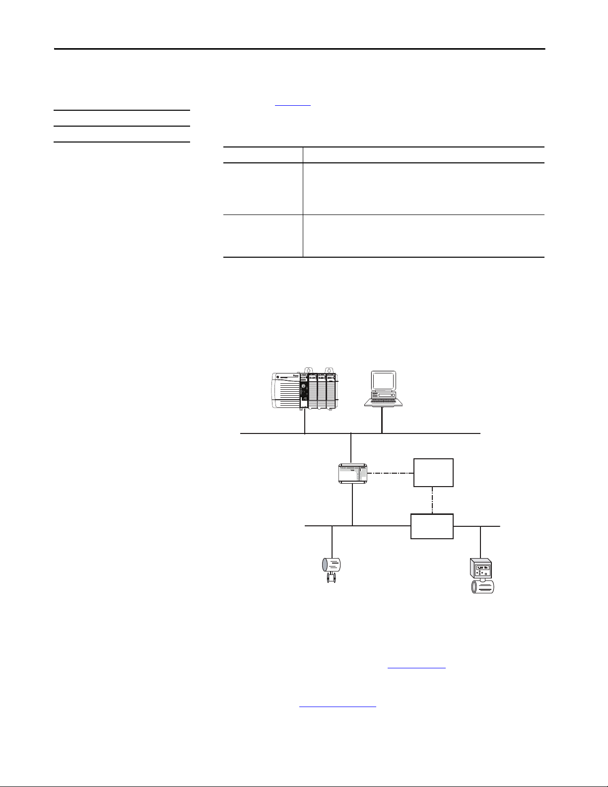
Communication Networks Chapter 3
RSFieldbus™ Software
24V DC
Power
Supply
Power
Conditioner
Field Device Field Device
1788-EN2FFR Linking Device
1756-L85E
Foundation Fieldbus Communication
Applies to these controllers:
ControlLogix 5580
Foundation Fieldbus is an open interoperable fieldbus that is designed for
process control instrumentation. The Foundation Fieldbus devices that are
described in Ta b l e 1 0
can be connected to the ControlLogix controller via
another network as shown in the following example.
Table 10 - Foundation Fieldbus Devices and Capabilities
Fieldbus Device Is used to
1788-EN2FFR • Bridge an EtherNet/IP network to Foundation Fieldbus.
1788-CN2FFR • Connect via low-speed serial (H1) connections.
• Connect via a low-speed serial (H1) and high-speed Ethernet (HSE) network
connections.
• Access devices directly via an OPC server.
• Use for standard communications only.
• Bridge a ControlNet network to a Foundation Fieldbus.
• Support redundant ControlNet media.
• Use for standard communications only.
Foundation Fieldbus distributes and executes control in the device. The
Foundation Fieldbus linking device does the following:
• Bridges from an EtherNet/IP network to an H1 connection
• Accepts HSE or EtherNet/IP messages and converts them to the
H1 protocol
Figure 14 - Foundation Fieldbus Example
Rockwell Automation Publication 1756-UM543K-EN-P - August 2020 49
For more information about using the Foundation Fieldbus devices available
from Rockwell Automation, see these publications:
• EtherNet/IP and ControlNet to FOUNDATION Fieldbus Linking
Device User Manual, publication 1788-UM057
• FOUNDATION Fieldbus Design Considerations Reference Manual,
publication PROCES-RM005
Page 50

Chapter 3 Communication Networks
• 1756-L85E
• 1756-IF8H or
• 1756-OF8H
HART Field Devices
HART Communication
Applies to these controllers:
ControlLogix 5580
HART (Highway Addressable Remote Transducer) is an open protocol that is
designed for process control instrumentation.
Device Is used to
1756 analog HART I/O modules:
1756-IF8H, 1756-IF8HK
1756-IF8IH
1756-IF16H, 1756-IF16HK
1756-IF16IH
1756-OF8H, 1756-OF8HK
1756-OF8IH
ProSoft interface
MVI56-H ART
• Act as HART master to allow communication with HART field devices.
• Interface directly with field devices (through built-in HART modems), which
mitigates the need for external hardware and more wiring.
• Provide access to more field device data, including voltage and current
measurements.
• Directly connect asset management software to HART devices.
• Support dif ferential wiring for environments where improved noise
immunity is needed (input modules).
• Use for standard communications only.
• Acquire data or control applications with slow update requirements, such as a
tank farm.
• Does not require external hardware to access HART signal.
• Does not provide a direct connection to asset management software.
• Use for standard communications only.
The HART protocol combines digital signals with analog signals to ready the
digital signal for the Process Variable (PV). The HART protocol also provides
diagnostic data from the transmitter.
Figure 15 - HART Protocol Example
For more information about using the HART I/O modules, see the
ControlLogix HART Analog I/O Modules User Manual, publication
1756-UM533
.
For more information about the ProSoft HART interface, see the
ProSoft Technologies
50 Rockwell Automation Publication 1756-UM543K-EN-P - August 2020
website at http://www.prosoft-technology.com.
Page 51
Applies to these controllers:
ControlLogix 5580
GuardLogix 5580
Chapter 4
Connect to a Controller
Top ic Pag e
Set the IP Address 51
Duplicate IP Address Detection 52
DNS Addressing 53
Update Controller Firmware 55
Before you can connect to the controller through the Ethernet or USB port,
you must configure the EtherNet/IP™ or USB driver in Linx-based software on
your workstation.
• The controller has an Ethernet port that supports 10 Mbps, 100 Mbps,
or 1 Gbps
Set the IP Address
• The controller has a USB port that uses a Type B receptacle. The port is
USB 2.0 compatible and runs at 12 Mbps.
• Install and configure a communication module in the chassis with the
controller as described in the installation instructions for the
communication module.
For more information on how to install communication drivers, see
EtherNet/IP Network Device User Manual, publication ENET-UM006
When the controller is in the out-of-the-box state, the following apply
regarding IP addresses:
• The controllers ship without an IP address.
• The controller is DHCP-enabled. That is, the controller is config ured to
obtain an IP address via a DHCP server.
If there is no DHCP server or the DHCP server is not configured to set
the IP address, you must set the IP Address manually.
.
Rockwell Automation Publication 1756-UM543K-EN-P - August 2020 51
Page 52

Chapter 4 Connect to a Controller
Requirements
To set the IP address, have the following:
• EtherNet/IP or USB drivers installed on the programming workstation
• MAC ID from the device, which is on the label on the side of the device
• Recommended IP address for the device
Other Methods to Set the IP Address
The controller supports the following methods to change the IP address:
• BOOTP/DHCP utility
• RSLinx® Classic software
• Studio 5000 Logix Designer® application
For more information on how to use these methods, see EtherNet/IP Network
Device User Manual, publication ENET-UM006
.
Duplicate IP Address Detection
The controller verifies that its IP address does not match any other network
device IP address when you perform either of these tasks:
• Connect the module to a EtherNet/IP network.
• Change the controller IP address.
If the controller IP address matches that of another device on the network, the
controller EtherNet/IP port transitions to Conflict mode. In Conflict mode,
these conditions exist:
• Network (NET) status indicator is solid red.
• The 4-character display indicates the conflict.
The display scrolls: <IP_address_of_this_module> Duplicate IP
<Mac_address_of_duplicate_node_detected>
For example: 192.168.1.1 Duplicate IP - 00:00:BC:02:34:B4
52 Rockwell Automation Publication 1756-UM543K-EN-P - August 2020
Page 53
Duplicate IP Address Resolution
When two devices on a network have IP addresses that conflict, the resolution
depends on the conditions in which the duplication is detected. This table
describes how duplicate IP addresses are resolved.
Duplicate IP Address Detection Conditions Resolution Process
• Both devices support duplicate IP address detection.
• Second device is added to the network after the first
device is operating on the network.
• Both devices support duplicate IP address detection
• Both devices were powered up at approximately the
same time.
One device supports duplicate IP address detection and a
second device does not
1. The device that began operation first uses the IP address and continues to operate without interruption.
2. The device that begins operation second detects the duplication and enters Conflict mode.
To assign a new IP address to the controller and leave Conflict mode, set the Network IP Address with the BootP
DHCP EtherNet/IP Commissioning Tool. See the EtherNet/IP Network Device User Manual, publication ENET-UM006
Both EtherNet/IP devices enter Conflict mode.
To resolve this conflict, follow these steps:
a. Assign a new IP address to the controller. Set the Network IP Address with the BootP DHCP EtherNet/IP
Commissioning Tool. See the EtherNet/IP Network Device User Manual, publication ENET-UM006.
b. Cycle power to the other device.
1. Regardless of which device obtained the IP address first, the device that does not support IP address detection uses
the IP address and continues to operate without interruption.
2. The device that supports duplicate IP address detection detects the duplication and enters Conflict mode.
To assign a new IP address to the controller and leave Conflict mode, set the Network IP Address with the BootP
DHCP EtherNet/IP Commissioning Tool. See the EtherNet/IP Network Device User Manual, publication ENET-UM006
Connect to a Controller Chapter 4
.
.
DNS Addressing
You can also use DNS addressing to specify a host name for a controller, a
domain name, and DNS servers. DNS addressing makes it possible to
configure similar network structures and IP address sequences under different
domains.
DNS addressing is necessary only if you refer to the controller by host name,
such as in path descriptions in MSG instructions.
To use DNS addressing, follow these steps.
1. Assign a host name to the controller.
A network administrator can assign a host name. Valid host names must
be IEC-1131-3 compliant.
2. Configure the controller parameters.
3. Configure the IP address, subnet mask, gateway address, a host name for
the controller, domain name, and primary/secondary DNS server
addresses.
In the DNS server, the host name must match the IP address of the
controller.
4. In the Logix Designer application, add the controller to the I/O
configuration tree.
Rockwell Automation Publication 1756-UM543K-EN-P - August 2020 53
Page 54

Chapter 4 Connect to a Controller
IMPORTANT If a child module resides in the same domain as its parent module, type the
host name. If the domain of the child module differs from the domain of its
parent module, type the host name and the domain name
(hostname.domainname)
IMPORTANT You can also use DNS addressing in a module profile in the I/O configuration
tree or in a message path. If the domain name of the destination module
differs from the domain name of the source module, then use a fully qualified
DNS name (hostname.domainname). For example, to send a message from
EN2T1.location1.companyA to EN2T1.location2.companyA, the host names
match, but the domains differ. Without the entry of a fully qualified DNS
name, the module adds the default domain name to the specified host name.
54 Rockwell Automation Publication 1756-UM543K-EN-P - August 2020
Page 55

Connect to a Controller Chapter 4
Update Controller Firmware
Applies to these controllers:
ControlLogix 5580
GuardLogix 5580
To update your controller firmware, complete these tasks:
• Determine Required Controller Firmware
• Obtain Controller Firmware
•Either Use ControlFLASH Plus or ControlFLASH Software to Update
Firmware or Use AutoFlash to Update Firmware
Firmware Upgrade Guidelines for Safety Controllers
IMPOR TANT Safety Consideration
You cannot update a controller that is safety locked.
The IEC 61508 functional safety standard requires impact analysis before
upgrading or modifying components in a certified, functional safety system.
This section provides high-level guidance on how you can perform the impact
analysis for safety controller hardware/firmware upgrades. Reference the
standard to make sure you fulfill all of the requirements as they relate to your
application.
When you upgrade controller firmware to a newer version, consider the
following:
• All major and minor firmware releases for GuardLogix controller
systems are certified for use in safety applications. As part of the
certification process, Rockwell Automation tests the safety-related
firmware functions (for example the CIP Safety™ communication
subsystems, embedded safety instruction execution, and safety-related
diagnostic functions). The firmware release notes identify changes to
safety-related functions.
• Perform an impact analysis of the planned firmware upgrade.
– Review of the firmware release notes for changes in safety-related
functionality.
– Review of hardware and firmware compatibility in the Product
Compatibility and Download site to identify potential compatibility
conflicts.
– Any modification, enhancement, or adaptation of your validated
software must be planned and analyzed for any impact to the
functional safety system as described in the 'Edit Your Safety
Application' section in the safety reference manual for your
controller.
• You must remove and re-generate the safety signature as part of the
firmware upgrade process. Use the online and offline edit process
described in the safety reference manual for your controller.
For more controller-specific information, see the GuardLogix 5580 and
Compact GuardLogix 5380 Safety Reference Manual, publication
1756-RM012
Rockwell Automation Publication 1756-UM543K-EN-P - August 2020 55
.
Page 56

Chapter 4 Connect to a Controller
IMPORTANT GuardLogix 5580 controllers have a different compiler than earlier
controllers. You must revalidate that applications on earlier controllers
compile correctly on GuardLogix 5580 controllers.
For product change management guidelines and definitions of how Rockwell
Automation manages product versions, see System Security Design Guidelines
Reference Manual, publication SECURE-RM001
.
For Example:
1. From the Product Compatibility and Download Center:
a. Review all firmware release notes, starting with the original firmware
revision through the new firmware revision, to identify any changes
that impact the safety-related implementation of the application.
b. Review hardware and firmware compatibility to identify any
restrictions between the original system components and the new
system components.
2. Perform a hazard and risk assessment for any changes identified during
the impact analysis and determine what additional testing is necessary.
3. Perform the online and offline edit process described in the safety
reference manual for your controller. You can restrict the 'Test the
Application' block to the testing identified by the hazard and risk
assessment.
Determine Required Controller Firmware
IMPORTANT The controller must be in Remote Program or Program mode and all major
recoverable faults must be cleared to accept updates.
The firmware major revision level must match the software major version level.
For example, if the controller firmware revision is 31.xxx, you must use the
Logix Designer application, version 31.
IMPOR TANT Safety Consideration
For a GuardLogix® system that includes a Safety Partner (SIL 3/PLe only), the
firmware on the primary controller and safety partner must match. When
you update the firmware on the primary controller, the safety partner
updates automatically.
56 Rockwell Automation Publication 1756-UM543K-EN-P - August 2020
Page 57

Connect to a Controller Chapter 4
Obtain Controller Firmware
You can obtain controller firmware in these ways:
• Firmware is packaged as part of the Studio 5000 Logix Designer
application installation.
IMPORTANT The firmware that is packaged with the software installation is the initial
release of the controller firmware. Subsequent firmware revisions to address
anomalies can be released during the life of a product.
We recommend that you check the Product Compatibility and Download
Center (PCDC) to determine if later revisions of the controller firmware are
available. For more information, see the next bullet.
• From the Rockwell Automation Product Compatibility and Download
Center (PCDC). You can check for available revisions of controller
firmware, and download controller firmware, associated files, and
product release notes.
ControlFLASH Plus™ software version 2.00.00 and later provides
integration with PCDC for an enhanced experience while you browse
for firmware revisions, downloads, release notes, and access to important
notices.
To vi si t P C D C , g o t o http://compatibility.rockwellautomation.com/
Pages/home.aspx.
Use ControlFLASH Plus or ControlFLASH Software to Update Firmware
For information on how to download, install, and use ControlFLASH Plus or
ControlFLASH™ software, see:
• ControlFLASH Plus Quick Start Guide, publication CFP-QS001
• ControlFLASH Firmware Upgrade Kit User Manual,
publication 1756-UM105
Rockwell Automation Publication 1756-UM543K-EN-P - August 2020 57
Page 58

Chapter 4 Connect to a Controller
Use AutoFlash to Update Firmware
To update your controller firmware with the AutoFlash feature, complete these
steps.
ATT EN TI ON : If the Secure Digital Card is locked and set to load on power-up,
then this update can be overwritten by firmware on the SD card.
1. Verify that the network connection is made and your network driver is
configured in Linx-based communication software.
2. Use the Logix Designer application to create a controller project.
3. On the Path bar, click Who Active.
4. On the Who Active dialog box, select your controller under the
communication driver you want to use, and click Update Firmware.
.
5. On the Choose Firmware Revision dialog, browse to the location of the
firmware files (C:\Program Files (x86)\ControlFLASH).
58 Rockwell Automation Publication 1756-UM543K-EN-P - August 2020
Page 59

6. Select the firmware revision, and click Update.
7. On the Confirmation dialog, click Yes.
Connect to a Controller Chapter 4
8. On the ControlFLASH Attention dialog, click OK.
The firmware update begins.
Allow the firmware update to complete without interruption. When the
firmware update is complete, the progress dialog closes.
Rockwell Automation Publication 1756-UM543K-EN-P - August 2020 59
Page 60

Chapter 4 Connect to a Controller
Notes:
60 Rockwell Automation Publication 1756-UM543K-EN-P - August 2020
Page 61

Start Using the Controller
Top ic Pag e
Create a Logix Designer Application Project 61
Additional Configuration for a GuardLogix Controller 62
Go Online with the Controller 71
Download to the Controller 77
Upload from the Controller 80
Choose the Controller Operation Mode 83
Reset Button 86
Chapter 5
Create a Logix Designer Application Project
Applies to these controllers:
ControlLogix 5580
GuardLogix 5580
Create a controller project by using the Studio 5000 Logix Designer®
application.
1. Create a new project and select the controller.
2. Define the properties of the controller.
• Choose the major revision of firmware for the controller.
• Choose the chassis size.
• Choose the slot for the controller.
• Choose a security authority option.
For detailed information on security, refer to the
Logix 5000 Controllers Security Programming Manual,
publication 1756-PM016
•Enter a description of the project.
.
Rockwell Automation Publication 1756-UM543K-EN-P - August 2020 61
Page 62

Chapter 5 Start Using the Controller
Additional Configuration for a GuardLogix Controller
Applies to these controllers:
GuardLogix 5580
GuardLogix® controllers require additional configuration after you create the
project. These topics describe how to configure your controller.
For a GuardLogix controller, the Logix Designer application creates a safety
task and a safety program. A main Ladder Diagram safety routine called
MainRoutine is also created within the safety program.
A red bar under the icon distinguishes safety programs and routines from
standard project components in the Controller Organizer.
Set the Safety Level for a GuardLogix Controller
The safety level declares to the Logix Designer application the intent of the
safety application. The safety level indicates whether the project is at safety
level SIL 2/PLd or SIL 3/PLe.
• The safety level required for an application is based on a required risk
assessment performed by the customer.
• The safety level achieved is determined by conformance to Safety
Integrity Level (SIL) and Performance Level (PL) requirements and
safety application requirements. See the GuardLogix 5580 and
Compact GuardLogix 5380 Controller Systems Safety Reference
Manual, publication 1756-RM012
You must specify the safety level:
•The default setting is SIL 2/PLd.
• You can only modify the setting offline, when the safety application is in
the Unlocked state and no safety signature exists.
• For SIL 3/PLe, you must have a 1756-L8SP Safety Partner installed to
the right of the primary controller.
• If you select SIL 3/PLe, a safety partner appears in the Controller
Organizer I/O tree. If you change the value back to SIL 2/PLd, the
safety partner disappears from the I/O tree.
.
62 Rockwell Automation Publication 1756-UM543K-EN-P - August 2020
Page 63

Start Using the Controller Chapter 5
Perform these steps to set the Safety Level:
1. On the Online toolbar, click the Controller Properties icon.
2. On the Controller Properties dialog, click the Safety tab.
3. On the Safety tab, select the Safety Level.
4. Click Apply.
5. Click OK.
Passwords for Safety-locking and Unlocking
Safety-locking the controller helps to protect safety control components from
modification. Only safety components, such as the safety task, safety programs,
safety routines, safety tags, and safety signature are affected. Standard
components are unaffected. You can safety-lock or -unlock the controller
project when online or offline.
The safety-lock and -unlock feature uses two separate passwords. Passwords are
optional.
IMPORTANT Rockwell Automation does not provide any form of password or security
override services. When products and passwords are configured, Rockwell
Automation encourages customers to follow good security practices and to
plan accordingly for password management.
For information on how to set passwords, see Set Passwords for Safety-locking
and Unlocking on page 191.
Rockwell Automation Publication 1756-UM543K-EN-P - August 2020 63
Page 64

Chapter 5 Start Using the Controller
Protect the Safety Signature in Run Mode
You can prevent the safety signature from being deleted while the controller is
in Remote Run mode, regardless of whether the safety application is locked or
unlocked.
IMPORTANT You must complete these steps before you create a safety signature or safety
lock the controller. Once a safety signature exists, or the application is safety
locked, the Protect Signature in Run Mode checkbox is not editable.
Follow these steps to protect the safety signature:
1. Open the Controller Properties dialog box.
2. Click the Safety tab.
3. Check Protect Signature in Run Mode.
4. Click OK.
64 Rockwell Automation Publication 1756-UM543K-EN-P - August 2020
Page 65

Start Using the Controller Chapter 5
Assign the Safety Network Number (SNN)
When you create controller projects, the Studio 5000 Logix Designer
application generates an SNN value automatically whenever it recognizes a
new subnet that contains CIP Safety™ devices:
• Each CIP Safety-capable port on the controller is assigned an SNN. The
GuardLogix 5580 controllers have two safety network numbers: one for
the EtherNet/IP™ port, and one for the backplane.
• If a bridge or adapter device is in the I/O tree and a child CIP Safety
device is added, the subnet that is created by the bridge or adapter is
assigned an SNN.
For typical users, the automatic assignment of a time-based SNN is sufficient.
However, manual assignment of the SNN is required if the following is true:
• One or more controller ports are on a CIP Safety subnet that already has
an established SNN.
• A safety project is copied to another hardware installation within the
same routable CIP Safety system.
Rockwell Automation recommends changing each SNN to the SNN already
established for that subnet, if one exists. That way, devices created later in the
project are automatically assigned the correct SNN.
For information regarding whether the controller or Ethernet ports are being
added to existing subnets, see the GuardLogix 5580 and Compact GuardLogix
5380 Controller Systems Safety Reference Manual, publication 1756-RM012.
Each safety network must have a unique safety network number. You must be
sure that a unique SNN is assigned to each CIP Safety network that contains
safety devices.
TIP Multiple safety network numbers can be assigned to a CIP Safety subnet or a
ControlBus™ chassis that contains multiple safety devices. However, for simplicity, we
recommend that each CIP Safety subnet has only one unique SNN.
For an explanation on the Safety Network Number, see the GuardLogix 5580
and Compact GuardLogix 5380 Controller Systems Safety Reference Manual,
publication 1756-RM012.
The SNN can be software-assigned (time-based) or user-assigned (manual).
These two formats of the SNN are described in the following sections:
Automatic Assignment of Time-based SNN on page 66
•
• Manual Assignment of SNN on page 67
Rockwell Automation Publication 1756-UM543K-EN-P - August 2020 65
Page 66

Chapter 5 Start Using the Controller
Automatic Assignment of Time-based SNN
When a new controller or device is created, a time-based SNN is automatically
assigned.
• Devices that are created directly under the controller port default to
having the same SNN as that port on the controller.
• For devices not directly under a controller port, subsequent new safety
device additions to the same CIP Safety network are assigned the same
SNN defined within the lowest address on that CIP Safety network.
The time-based format sets the SNN value as the date and time when the
number was generated, according to the computer running the configuration
software.
Figure 16 - Time-based Format
66 Rockwell Automation Publication 1756-UM543K-EN-P - August 2020
Page 67

Start Using the Controller Chapter 5
Manual Assignment of SNN
Manual assignment is useful if you lay out your network and put the SNNs on
your network diagram. It may be easier to read SNNs from a diagram than it is
to copy and paste them from multiple projects.
Manual assignment of the SNN is required if the following is true:
• One or more controller ports are on a CIP Safety subnet that already has
an established SNN.
• A safety project is copied to another hardware installation within the
same routable CIP Safety system.
IMPORTANT If you assign an SNN automatically or manually, make sure that system
expansion does not result in a duplication of SNN and unique node reference
combinations.
A warning appears if your project contains duplicate SNN and unique node
reference combinations. You can still verify the project, but Rockwell
Automation recommends that you resolve the duplicate combinations.
However, there can be safety devices on the routable safety network that have
the same SNN and node address and are not in the project. In this case, these
safety devices are unknown to the Logix Designer application, and you will
not see a warning.
If two different devices have the same node references, the safety system
cannot detect a packet received by one device that was intended for the other
device.
If there are duplicate unique node references, as the system user, you are
responsible for proving that an unsafe condition cannot result.
Rockwell Automation Publication 1756-UM543K-EN-P - August 2020 67
Page 68

Chapter 5 Start Using the Controller
Follow these steps to change the controller SNNs to a manual assignment:
1. On the Online toolbar, click the Controller Properties icon
2. On the Controller Properties dialog, click the Safety tab.
3. On the Safety tab, click to the right of the safety network number
for the port that you want to change.
4. On the Safety Network Number dialog box, select Manual
5. Enter the SNN as a value from 1…9999 (decimal).
6. Click OK.
You can allow the Logix Designer application to automatically assign an SNN,
or you can assign the SNN manually.
68 Rockwell Automation Publication 1756-UM543K-EN-P - August 2020
Page 69

Start Using the Controller Chapter 5
Copy and Paste a Safety Controller Safety Network Number
If you must apply a Safety Network Number (SNN) to other safety controllers,
you can copy and paste the SNN. There are multiple ways to copy and paste
safety controller SNNs.
Copy a Safety Controller SNN
From the Controller Properties Safety Tab:
1. On the Safety tab, click in the SNN field that you want to copy.
2. Press Ctrl-C to copy the SNN.
From the Safety Network Number dialog:
1. On the Controller Properties dialog, click the Safety tab.
2. Click to the right of the safety network number to open the Safety
Network Number dialog.
3. On the Safety Network Number dialog, either click Copy, or click in the
SNN field and Press Ctrl-C.
Rockwell Automation Publication 1756-UM543K-EN-P - August 2020 69
Page 70

Chapter 5 Start Using the Controller
Paste a Safety Controller SNN
1. On the Controller Properties dialog, click the Safety tab.
2. Click to the right of the safety network number to open the Safety
Network Number dialog.
3. On the Safety Network Number dialog, either click Paste, or click in the
SNN field and Press Ctrl-V.
4. Click OK.
5. On the Controller Properties Safety tab, click OK.
70 Rockwell Automation Publication 1756-UM543K-EN-P - August 2020
Page 71

Start Using the Controller Chapter 5
Go Online with the Controller
Applies to these controllers:
ControlLogix 5580
GuardLogix 5580
To go online with the controller, you must first specify a communication path
in the Logix Designer application.
TIP For this section, the USB port was chosen as the communication path. Other paths
through the embedded Ethernet port or via the backplane are also possible.
Use RSWho
1. Open or create a Logix Designer application project.
2. In the application, click RSWho.
3. Expand the communication path and select the controller.
4. If you want to store the path in the project file, click Set Project Path.
If you store the project path in the project, then you do not have to
choose the path each time you go online.
5. After choosing the communication path, click Go Online in the
Who Active dialog box.
Rockwell Automation Publication 1756-UM543K-EN-P - August 2020 71
Page 72

Chapter 5 Start Using the Controller
Go Online will use the highlighted node in the Who Active tree,
regardless of the setting for Path in Project. For more information on the
Who Active dialog box, see the Logix Designer Online Help.
See Additional Considerations for Going Online with a GuardLogix
Controller on page 73.
Use a Recent Communication Path
You can also select a recent communications path and go online or apply it to
your project.
1. In the application, click the arrow that is on the Path bar.
2. On the Select Recent Communications Path dialog box, choose the
path.
3. To store the path in your project, click Set Project Path.
4. Click Go Online.
For more information on the Select Recent Communications Path dialog box,
see the Logix Designer Online Help.
Once you have established a communication path, then you can choose Go
Online from the Controller Status menu when you are working in the project.
See Additional Considerations for Going Online with a GuardLogix
Controller on page 73.
72 Rockwell Automation Publication 1756-UM543K-EN-P - August 2020
Page 73

Start Using the Controller Chapter 5
Additional Considerations for Going Online with a GuardLogix Controller
Applies to these controllers:
GuardLogix 5580
The Logix Designer application determines whether you can go online with a
target controller based on whether the offline project is new or whether
changes occurred in the offline project. If the project is new, you must first
download the project to the controller. If changes occurred to the project, you
are prompted to upload or download. If no changes occurred, you can go
online to monitor the execution of the project.
A number of factors affect these processes, including Project to Controller
Match feature, the safety status and faults, the existence of a safety signature,
the safety-lock/-unlock status of the project and the controller, and the
configured safety level disagreeing with the presence or absence of a partner in
the chassis.
Match Project to Controller
The Match Project to Controller feature affects the download, upload, and go
online processes of standard and safety projects. This feature is located on the
Controller Properties Advanced tab.
If the Match Project to Controller feature is enabled in the offline project, the
Logix Designer application compares the serial number of the controller in the
offline project to that of the connected controller. If they do not match, you
must cancel the download/upload, connect to the correct controller, or
confirm that you are connected to the correct controller that updates the serial
number in the project to match the target controller.
Rockwell Automation Publication 1756-UM543K-EN-P - August 2020 73
Page 74

Chapter 5 Start Using the Controller
Firmware Revision Matching
Firmware revision matching affects the download process. If the revision of the
controller does not match the revision of the project, you are prompted to
update the firmware of the controller. The Logix Designer application lets you
update the firmware as part of the download sequence.
IMPORTANT To update the firmware of the controller, first install a firmware upgrade
kit. An upgrade kit ships on a supplemental DVD along with the Studio
5000® environment.
TIP You can also upgrade the firmware by choosing ControlFLASH Plus™ or
ControlFLASH™ from the Tools menu in the Logix Designer application.
Safety Status/Faults
Uploading program logic and going online is allowed regardless of safety status.
Safety status and faults only affect the download process.
You can view the safety status via the Safety tab on the Controller Properties
dialog box.
74 Rockwell Automation Publication 1756-UM543K-EN-P - August 2020
Page 75

Start Using the Controller Chapter 5
Safety Signature and Safety-locked and -unlocked Status
The existence of a safety signature and the safety-locked or -unlocked status of
the controller affect both the upload and download processes.
The safety signature and the safety lock status are uploaded with the project.
For example, if the project in the controller was safety-unlocked, the offline
project remains safety-unlocked following the upload, even if it was locked
prior to the upload.
Following an upload, the safety signature in the offline project matches the
controller’s safety signature.
The safety lock status always uploads with the project, even when there is no
safety signature.
The existence of a safety signature, and the controller’s safety-lock status,
determines whether or not a download can proceed.
Table 11 - Effect of Safety-lock and safety signature on Download Operation
Safety-lock Status Safety Signature Status Download Functionality
safety signature in the offline project matches
the safety signature in the controller.
Controller safety-unlocked
safety signatures do not match. If the controller had a safety signature, it is automatically deleted, and the entire project is
safety signatures match. If the offline project and the controller are safety-locked, all standard project components are
Controller safety-locked
safety signatures do not match. You must first safety-unlock the controller to allow the download to proceed. If the controller
All standard project components are downloaded. Safety tags are reinitialized to the values
they had when the safety signature was created. Safety lock status matches the status in the
offline project.
downloaded. Safety lock status matches the status in the offline project.
downloaded and safety tags are reinitialized to the values they had when the safety signature
was created.
If the offline project is not safety-locked, but the controller is, the download is blocked and you
must first unlock the controller to allow the download to proceed.
had a safety signature, it is automatically deleted, and the entire project is downloaded. Safety
lock status matches the status in the offline project.
Rockwell Automation Publication 1756-UM543K-EN-P - August 2020 75
Page 76

Chapter 5 Start Using the Controller
Checks for Going Online with a GuardLogix Controller
For a safety project, the Logix Designer application checks for the following:
• Do the offline project and controller serial numbers match (if Project
to Controller Match is selected)?
• Does the offline project contain changes that are not in the controller
project?
• Do the revisions of the offline project and controller firmware
match?
• Are either the offline project or the controller safety-locked?
• Do the offline project and the controller have compatible safety
signatures?
Table 12 - Connect to the Controller with a Safety Project
If the software indicates Then
Unable to connect to controller. Mismatch between the offline project and the
controller serial number. Selected controller may be the wrong controller.
Unable to connect to controller. The revision of the offline project and the controller’s
firmware are not compatible.
You need to upload or download to go online by using the open project. Choose one of the following options:
Unable to connect in a manner that preserves safety signature. The firmware minor
revision on the controller is not compatible with safety signature in offline project.
Unable to connect to controller. Incompatible safety signature cannot be deleted while
project is safety-locked.
Connect to the correct controller, select another project file, or choose the Update
project serial number checkbox and choose Go Online… to connect to the controller
and update the offline project serial number to match the controller.
Choose one of the following options:
• Choose Update Firmware. Choose the required revision and click Update. Click Yes to
confirm your selection.
IMPORTANT: The online project is deleted.
• To preserve the online project, cancel the online process and install a version of the
Studio 5000 environment that is compatible with the firmware revision of your
controller.
• Upload to update the offline project.
• Download to update the controller project.
• Choose File to select another offline project.
• To preserve the safety signature when the firmware minor revision is incompatible,
update the firmware revision in the controller to exactly match the offline project.
Then go online to the controller.
• To proceed with the download despite the safety signature incompatibility, click
Download. The safety signature is deleted.
IMPORTANT: The safety system requires revalidation.
Cancel the online process. You must safety-unlock the offline project before attempting
to go online.
When the controller and the Logix Designer application are online, the safetylocked status and safety signature of the controller match the controller’s
project. The safety-lock status and safety signature of the offline project are
overwritten by the controller. If you do not want the changes to the offline
project to be permanent, do not save the project file following the go online
process.
76 Rockwell Automation Publication 1756-UM543K-EN-P - August 2020
Page 77

Start Using the Controller Chapter 5
Download to the Controller
Applies to these controllers:
ControlLogix 5580
GuardLogix 5580
When you download a project to the controller, it copies the project from the
Logix Designer application onto the controller.
Use Who Active
You can use the features of the Who Active dialog box to download to your
controller after you have set the communication path. Complete these steps to
download to the controller.
1. After choosing the communication path, click Download in the
Who Active dialog box.
2. After reading the warnings in the Download dialog box, click
Download.
Rockwell Automation Publication 1756-UM543K-EN-P - August 2020 77
Page 78

Chapter 5 Start Using the Controller
Use the Controller Status Menu
After you choose a communication path in the Logix Designer application, you
can use the Controller Status menu to download to the controller. To
download, from the Controller Status menu, choose Download.
Figure 17 - Download Via the Controller Status Menu
TIP After the download completes, the project name appears on the scrolling status
display.
Additional Considerations for Download to a GuardLogix Controller
Applies to these controllers:
GuardLogix 5580
For a safety project, the Logix Designer application compares the following
information in the offline project and the controller:
• Controller serial number (if project to controller match is selected)
• Firmware major and minor revisions
•Safety status
• Safety signature (if one exists)
• Safety-lock status
• Safety Partner (if one exists). The Logix Designer application does
not allow the download of a project configured for SIL 2 if a safety
partner is to the right of the primary controller.
After the checks all pass, a download confirmation dialog appears. Click
Download.
The Logix Designer application displays status messages in the download
dialog, progress screen, and the Errors window.
78 Rockwell Automation Publication 1756-UM543K-EN-P - August 2020
Page 79

Start Using the Controller Chapter 5
If the software indicates: Then:
Unable to download to the controller. Mismatch between the offline project
and the controller serial number. Selected controller may be the wrong
controller.
Unable to download to the controller. The major revision of the offline project
and the controller’s firmware are not compatible.
Unable to download a SIL 2 application, Safety Partner is Present. Remove the safety partner.
Unable to download to controller. The safety partner is missing or unavailable. Cancel the download process. Install a compatible safety partner before attempting to
Unable to download to controller. The firmware revision of the safety partner is
not compatible with the primary controller.
Unable to download to controller. Safety partnership has not been established. Cancel this download process and attempt a new download.
Unable to download to controller. Incompatible safety signature cannot be
deleted while the project is safety-locked.
Cannot download in a manner that preserves the safety signature. Controller’s
firmware minor revision is not compatible with safety signature in offline
project.
Unable to download to controller. Controller is locked. Controller and offline
project safety signatures do not match.
Downloading safety signature... The safety signature is present in the offline project and is downloading.
Reloading safety signature... The safety signature is present in the offline project and is not downloaded, because a matching
Connect to the correct controller or verify that this is the correct controller. If it is the correct
controller, check the Update project serial number checkbox to allow the download to proceed.
The project serial number is modified to match the controller serial number.
Choose Update Firmware. Choose the required revision and click Update. Click Yes to confirm your
selection.
download.
Update the firmware revision of the safety partner. Choose Update Firmware. Choose the
required revision and click Update. Click Yes to confirm your selection.
Cancel the download. To download the project, you must safety-unlock the offline project, delete
the safety signature, and download the project.
IMPORTANT: The safety system requires revalidation.
• If the firmware minor revision is incompatible, to preserve the safety signature, update the
firmware revision in the controller to exactly match the offline project. Then download the
offline project.
• To proceed with the download despite the safety signature incompatibility, click Download.
The safety signature is deleted.
IMPORTANT: The safety system requires revalidation.
Choose Unlock. The Safety Unlock for Download dialog box appears. If the Delete Signature
checkbox is selected and you choose Unlock, click Yes to confirm the deletion.
signature exists in the controller and is reloaded from there.
Following a successful download, the safety-locked status and safety signature
of the controller match the project that was downloaded. Safety data is
initialized to the values that existed when the safety signature was created.
Rockwell Automation Publication 1756-UM543K-EN-P - August 2020 79
Page 80

Chapter 5 Start Using the Controller
Upload from the Controller
Applies to these controllers:
ControlLogix 5580
GuardLogix 5580
When you upload a project from the controller, it copies the project from the
controller to the Logix Designer application.
Use Who Active
You can use the features of the Who Active dialog box to upload from your
controller after you have set the communication path. Complete these steps to
upload from the controller.
1. After choosing the communication path, click Upload on the
Who Active dialog box.
2. On the Connected to Upload dialog box, verify that the project is the
one you want to upload.
3. Click Upload.
For more information on the Connected To upload dialog box, see the Logix
Designer Online Help.
80 Rockwell Automation Publication 1756-UM543K-EN-P - August 2020
Page 81

Start Using the Controller Chapter 5
Use the Controller Status Menu
After you have chosen a communication path in the Logix Designer
application, you can use the Controller Status menu to upload from the
controller.
1. From the Controller Status menu, choose Upload.
Figure 18 - Upload Via the Controller Status Menu
2. On the Connected to Upload dialog box, verify that the project is the
one you want to upload.
3. Click Upload.
Rockwell Automation Publication 1756-UM543K-EN-P - August 2020 81
Page 82
Chapter 5 Start Using the Controller
Additional Considerations for
Upload from a GuardLogix
For a safety project, the Logix Designer application compares the following
information in the project and the controller:
• Controller serial number (if project to controller match is selected)
Controller
Applies to these controllers:
GuardLogix 5580
• Open project to the controller project
• Firmware major and minor revisions
• Safety signature (if one exists)
IMPORTANT An upload is allowed regardless of the Safety status and the Safety Locked
state of the offline project and controller. The locked status follows the state
of the uploaded project.
Upload Behavior: Response:
If the project to controller match is enabled, the Logix Designer application
checks whether the serial number of the open project and the seri al number of
the controller match.
The Logix Designer application checks whether the open project matches the
controller project.
The Logix Designer application checks for changes in the offline project. • If there are no changes in the offline project, you can go online without uploading. Click Go
Uploading safety signature... This message appears during the upload only if a safety signature matching the one in the
• Connect to the correct controller or verify that this is the correct controller.
• Select a new projec t to upload into or select another project by choosing Select File.
• If it is the correct controller, select the Update projec t serial number checkbox to allow the
download to proceed. The project serial number is modified to match the controller serial
number.
• If the projects do not match, you must select a matching file or cancel the upload process.
• If the projects match, the soft ware checks for changes in the offline (open) project.
Online.
• If there are changes in the open project that are not present in the controller, you can choose
to upload the project, cancel the upload, or select another file.
controller doe not exist in the offline project.
If you choose Upload, the standard and safety applications are uploaded.
If a safety signature exists, it is also uploaded. The safety-lock status of
the project reflects the original status of the online (controller) project.
TIP Prior to the upload, if an offline safety signature exists, or the offline project is
safety-locked but the controller is safety-unlocked or has no safety signature,
the offline safety signature and safety-locked state are replaced by the online
values (safety-unlocked with no safety signature). If you do not want to make
these changes permanent, do not save the offline project following the
upload.
82 Rockwell Automation Publication 1756-UM543K-EN-P - August 2020
Page 83

Start Using the Controller Chapter 5
Choose the Controller
Use this table as a reference when determining your controller operation mode.
Operation Mode
Applies to these controllers:
ControlLogix 5580
GuardLogix 5580
Keyswitch
Position
RUN Run mode—The controller is actively
REM Remote Run mode—This mode is
PROG Program mode—This controller mode
(1) Moving the keyswitch from Run to Remote leaves the controller in the Remote Run mode, while moving the switch from Program to Remote leaves the controller in the Remote Program mode. You
cannot choose Remote Test mode by the keyswitch alone, it is only available via the Logix Desig ner application.
Available Controller Modes In this mode you can: In this mode you cannot:
(1)
controlling the process/machine. Projects
cannot be edited in the Logix Designer
application when in Run mode.
identical to Run mode except you can edit
the project online, and change the
controller mode through the Logix
Designer application.
Remote Program mode—This mode
functions like Program mo de, except you
can change the controller mode through
the Logix Designer application.
Remote Test mode—This controller
mode executes code, but I/O is not
controlled. You can edit the project
online, and change the controller mode
through the Logix Designer application.
Output modules are commanded to their
Program mode state (on, off, or hold).
does not execute code or control I/O, but
editing operations are available.
Output modules are commanded to their
Program mode state (On, Off, or Hold).
In this position, controller modes cannot
be changed through the Logix Designer
application.
• Turn outputs to the state
commanded by the logic of the
project.
•Execute (scan) tasks
• Send messages
• Send and receive data in response to
a message from another controller
• Produce and consume tags
• Turn outputs to the state
commanded by the logic of the
project.
•Execute (scan) tasks
• Change the mode of the controller
via the Logix Designer application
• While online, edit the project
• Send messages
• Send and receive data in response to
a message from another controller
• Produce and consume tags
• Turn outputs to their configured
state for Program mode
• Change the mode of the controller
via the Logix Designer application
• Download a project
• Schedule a ControlNet network
• While online, edit the project
• Send and receive data in response to
a message from another controller
• Produce and consume tags
• Turn outputs to their configured
state for Program mode
•Execute (scan) tasks
• Change the mode of the controller
via the Logix Designer application
• While online, edit the project
• Send messages
• Send and receive data in response to
a message from another controller
• Produce and consume tags
• Turn outputs to their configured
state for Program mode
• Download a project
• Schedule a ControlNet network
• While online, edit the project
• Send and receive data in response to
a message from another controller
• Produce and consume tags
• Turn outputs to their configured
state for Program mode
• Change the mode of the
controller via the Logix Designer
application
• Download a project
• Schedule a ControlNet® network
• While online, edit the project
• Turn outputs to their configured
state for Program mode
• Download a project
• Schedule a ControlNet network
• Turn outputs to the state
commanded by the logic of the
project.
•Execute (scan) tasks
• Turn outputs to the state
commanded by the logic of the
project.
• Download a project
• Schedule a ControlNet network
• Send messages
• Turn outputs to the state
commanded by the logic of the
project.
•Execute (scan) tasks
• Change the mode of the
controller via the Logix Designer
application
• Send messages
ATTENTION:
Run mode is used only when all
conditions are safe.
You are able to modify a project
file online in Remote Run mode.
Be sure to control outputs with
care to avoid injur y to personnel
and damage to equipment.
Outputs are commanded to
their Program mode state,
which can cause a dangerous
situation.
Do not use Program mode as an
emergency stop (E-stop).
Program mode is not a safety
device.
Outputs are commanded to
their Program mode state,
which can cause a dangerous
situation.
Rockwell Automation Publication 1756-UM543K-EN-P - August 2020 83
Page 84
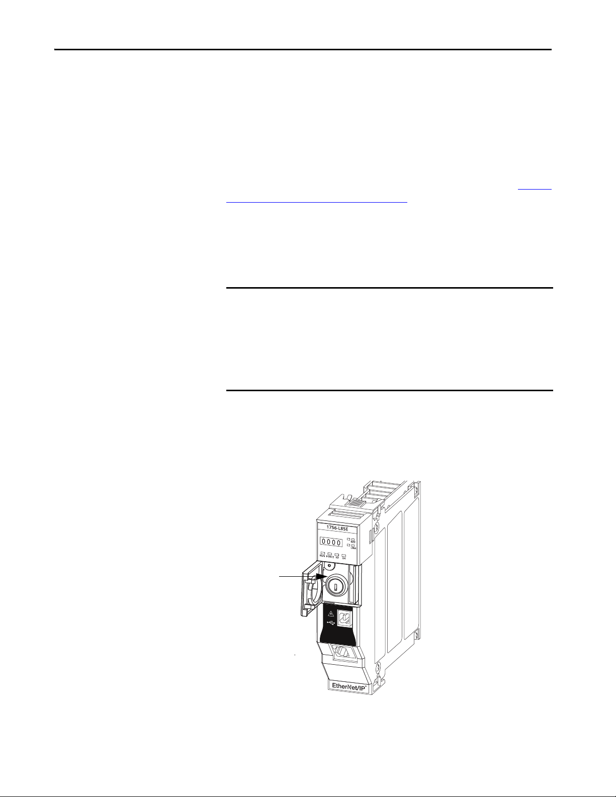
Chapter 5 Start Using the Controller
keyswitch
Use the keyswitch to Change the Operation Mode
To change the operation mode, use the controller keyswitch. The controller
keyswitch provides a mechanical means to enhance controller and control
system security. You must physically move the keyswitch on the controller to
change its operating mode from RUN, to REM, or to PROG.
When the keyswitch on the controller is set to RUN mode, features like online
editing, program downloads, and firmware updates are prohibited. See Choose
the Controller Operation Mode on page 83 for a complete list of prohibited
features.
The physical keyswitch can complement other authorization and
authentication methods that similarly control user-access to the controller,
such as the FactoryTalk® Security service.
IMPORTANT During runtime, we recommend that you place the controller keyswitch in
RUN mode and remove the key (if applicable) from the switch. This can help
discourage unauthorized access to the controller or potential tampering
with the program of the controller, configuration, or device firmware.
Place the keyswitch in REM or PROG mode during controller commissioning
and maintenance and whenever temporary access is necessary to change
the program, configuration, or firmware of the product.
The keyswitch on the front of the controller can be used to change the
controller to one of these modes:
•Run (RUN)
•Remote (REM)
•Program (PROG)
84 Rockwell Automation Publication 1756-UM543K-EN-P - August 2020
Page 85

Start Using the Controller Chapter 5
Use the Logix Designer Application to Change the Operation Mode
When you are online with the controller, and the controller keyswitch is set to
Remote (REM or the center position), then you can use Logix Designer to
change the operation mode.
The Controller Status menu lets you specify these operation modes:
•Remote Program
•Remote Run
• Remote Test
Figure 19 - Operation Mode
TIP For this example, the controller keyswitch is set to Remote mode. If your controller
keyswitch is set to Run or Program modes, the menu options change.
Rockwell Automation Publication 1756-UM543K-EN-P - August 2020 85
Page 86

Chapter 5 Start Using the Controller
ControlLogix and GuardLogix
controllers Reset Button
OK
Safety Partner Reset Button
Reset Button
Applies to these controllers:
ControlLogix 5580
GuardLogix 5580
You can reset the ControlLogix® and GuardLogix controllers, and the
1756-L8SP Safety Partner, with the reset button. The reset button is only read
during a power-up or restart. If you press the reset button at another time, it has
no effect.
For a GuardLogix controller, the Safety Locked status or safety signature does
not prevent you from performing a controller reset. Because the application is
cleared from the controller during a reset, the safety level of the controller is
cleared also. When you download a safety project to the controller, the safety
level is set to the level specified in the project.
A controller has two stages of reset:
• A Stage 1 reset clears the application program and memory, but retains
the IP address and all network settings. A stage 1 reset occurs only if the
controller contains a user application. See Stage 1 Reset
on page 87.
• A Stage 2 reset returns the controller to out-of box settings (including
firmware), and clears all network settings. A stage 2 reset occurs only if
the controller does not contain a user application, and the current
controller firmware is not a 1.x version. See Stage 2 Reset
on page 88.
The Safety Partner reset returns the safety partner to out-of box settings
(including firmware). See Safety Partner Reset
on page 89.
IMPORTANT Because port enable/disable status is associated with the application
program, the controller Ethernet port becomes enabled after a Stage 1 or
Stage 2 reset.
WARNING: When you press the reset button while power is on, an Electric
Arc can occur. This could cause an explosion in hazardous location
installations. Be sure that power is removed or the area is nonhazardous
before proceeding.
86 Rockwell Automation Publication 1756-UM543K-EN-P - August 2020
Page 87

Start Using the Controller Chapter 5
Stage 1 Reset
The stage 1 reset:
• Clears the application program.
• Retains the network settings for the embedded Ethernet port.
• Retains APR (motion position info) information.
• Retains all PTP configuration (Time Synchronization) parameters.
• Retains Wall Clock Time within the energ y retention capability of the
module.
• Creates a timestamped entry in the Controller Log that a Stage 1 Reset
event has occurred.
• Resets the controller to begin the controller start up process.
• Prevents the controller from loading firmware or software from the SD
card on this first start up after the reset, regardless of the setting on the
SD card, and without modifying the SD card contents (the writeprotect setting is irrelevant). An SD card will reload (if configured to do
so) on subsequent powerup situations.
• Enables the Ethernet Port, if it was previously disabled.
To perform a Stage 1 reset, complete these steps. This process assumes that an
SD card is installed in the controller.
1. Power down the controller.
2. Remove the key from the keyswitch.
3. Open the front door on the controller.
4. Use a small tool with a diameter of a paper clip, to press and hold the
reset button. The button is recessed behind the panel.
5. While holding in the reset button, power up the controller.
6. Continue to hold the reset button while the 4-character display cycles
through CLR, 4, 3, 2, 1, Project Cleared.
7. After Project Cleared appears, release the reset button.
IMPORTANT If you release the reset button before Project Cleared scrolls across the
display, the controller continues with powerup and does not reset.
After a Stage 1 reset is performed, load a Logix Designer application project to
the controller in these ways:
• Download the project from the Logix Designer application - For more
information, see Download to the Controller
on page 77
• Cycle power on the controller to load a project from the SD card.
This option works only if the project stored on the SD card is
configured to load the project on powerup.
Rockwell Automation Publication 1756-UM543K-EN-P - August 2020 87
Page 88

Chapter 5 Start Using the Controller
Stage 2 Reset
The stage 2 reset:
• Returns the module to revision 1.x firmware (the out-of-box firmware
revision).
• Clears all user settings to the out-of-box values including network and
time synchronization settings.
• Resets the controller to begin the controller start up process.
• There will be no entries in the controller log after a Stage 2 reset, but
saved logs on the SD card remain.
Follow these steps to perform a Stage 2 reset:
1. Power down the controller.
2. Remove the key from the keyswitch.
3. Open the front door on the controller.
4. Remove the SD card.
5. Use a small tool with a diameter of a paper clip, to press and hold the
reset button. The button is recessed behind the panel.
6. While holding in the reset button, power up the controller.
7. Continue to hold the reset button while the 4-character display cycles
through DFLT, 4, 3, 2, 1, Factory Default.
8. After Factory Default appears, release the reset button.
9. On your workstation, delete all of the files on the SD card.
10. Power down the controller.
11. Reinstall the SD card.
12. Powerup the controller.
13. Verify that the controller is at firmware revision 1.x, and the controller is
set to DHCP.
After a Stage 2 reset is performed, you must complete these tasks to use the
controller again:
• Configure the Ethernet ports, set the desired EtherNet/IP mode, and set
the controller IP address configuration. For more information, see
Connect to a Controller
on page 51.
• Update the firmware revision - For more information, see Upd ate
Controller Firmware on page 55.
• Download a Logix Designer application project to the controller in one
of these ways:
– Download the project from the Logix Designer application - For
more information, see Download to the Controller
on page 77.
– Cycle power on the controller to load a project from the SD card.
This option works only if the project stored on the SD card is
configured to load the project on powerup.
88 Rockwell Automation Publication 1756-UM543K-EN-P - August 2020
Page 89

Start Using the Controller Chapter 5
Safety Partner Reset
Follow these steps to perform a safety partner reset:
1. Power down the safety partner.
2. Use a small tool with a diameter of a paper clip, to press and hold the
reset button. This button is recessed 5 mm (0.19 in.) behind the panel.
3. While holding in the reset button, power up the safety partner.
4. Continue to hold the reset button while the 4-character display cycles
through DFLT, 4, 3, 2, 1, Factory Default.
5. After Factory Default appears, release the reset button.
Rockwell Automation Publication 1756-UM543K-EN-P - August 2020 89
Page 90

Chapter 5 Start Using the Controller
Notes:
90 Rockwell Automation Publication 1756-UM543K-EN-P - August 2020
Page 91

Applies to these controllers:
ControlLogix 5580
GuardLogix 5580
Chapter 6
Use the Secure Digital Card
Top ic Pag e
Considerations for Storing and Loading a Safety Project 93
Store to the SD Card 94
Load from the SD Card 98
Other S ecure Digit al Card Tasks 100
The controllers ship with a Secure Digital (SD) card installed. We recommend
that you leave the SD card installed, so if a fault occurs, diagnostic data is
automatically written to the card. Rockwell Automation can then use the data
to help investigate the cause of the fault.
We recommend that you use the SD cards available from
Rockwell Automation:
• 2 GB SD card, catalog number 1784-SD2
• CodeMeter CmCard SD, 4 GB, catalog number 9509-CMSDCD4
(when license-based source protection and execution protection features
are enabled)
While other SD cards can be used with the controller, Rockwell Automation
has not tested the use of those cards with the controller and you could
experience data corruption or loss.
SD cards that are not provided by Rockwell Automation can have different
industrial, environmental, and certification ratings as those cards that are
available from Rockwell Automation. These cards can have difficulty with
survival in the same industrial environments as the industrially rated versions
available from Rockwell Automation.
The memory card that is compatible with your ControlLogix® controller is
used to load or store the contents of user memory for the controller.
When you use the Store feature, the project that is stored on the SD card
matches the project in the controller memory at that time. Changes that you
make after you store the project are not reflected in the project on the SD card.
If you make changes to the project in the controller memory but do not store
those changes, the next time that you load the project from the SD card to the
controller, you overwrite the changes.
Rockwell Automation Publication 1756-UM543K-EN-P - August 2020 91
Page 92

Chapter 6 Use the Secure Digital Card
IMPORTANT Do not remove the SD card while the controller is reading from, or writing to,
the card. If you remove the card during either activity, the data on the card
or controller can become corrupt.
Additionally, the controller firmware at the time when the card is removed
can become corrupted. Leave the card in the controller until the OK status
indicator turns solid green.
If an SD card is installed, you can see the contents of the card on the
Nonvolatile Memory tab of the Controller Properties dialog box. If a safety
application is stored on the card, the safety-lock status and the safety signature
are shown.
The project must be online to see the contents of the SD card.
For detailed information on how to use nonvolatile memory, refer to the Logix
5000 Controllers Nonvolatile Memory Programming Manual, publication
1756-PM017
.
92 Rockwell Automation Publication 1756-UM543K-EN-P - August 2020
Page 93

Use the Secure Digital Card Chapter 6
Considerations for Storing and Loading a Safety Project
Applies to these controllers:
GuardLogix 5580
Only GuardLogix® 5580 controllers support safety projects. ControlLogix
5580 controllers do not support safety projects.
You cannot store a safety project if the safety task status is Safety Task
Inoperable. When you store a safety project, the controller firmware is also
stored to the SD card.
If no application project exists in the controller, you can save only the firmware
of the safety controller if a valid partnership exists. A firmware-only load does
not clear a Safety Task Inoperable condition.
If a safety signature exists when you store a project, the following occurs:
• Safety tags are stored with the value they had when the signature was
first created.
• Standard tags are stored with their current values.
• The current safety signature is saved.
When you store a safety application project on an SD card,
Rockwell Automation recommends you select Program (Remote Only) as the
Load mode, that is, the mode that the controller enters after a project is loaded
from the SD card.
IMPORTANT To prevent the firmware stored on the SD card from overwriting newly-
updated firmware:
• The update process first checks the load option on the SD card, and
changes the load option to User Initiated if necessary.
• The firmware update proceeds.
• The controller resets.
• The load option remains set to User Initiated.
If the SD card is locked, the load option does not change, and the firmware
that is stored on the SD card can overwrite the newly-updated firmware.
Rockwell Automation Publication 1756-UM543K-EN-P - August 2020 93
Page 94

Chapter 6 Use the Secure Digital Card
Store to the SD Card
Applies to these controllers:
ControlLogix 5580
GuardLogix 5580
We recommend that you back up your Logix Designer project to an SD card
on a regular basis.
If a major nonrecoverable fault occurs that removes the program from the
controller memory, the backup copy on the SD card can be automatically
restored to the controller to quickly resume normal controller operation.
To store a project to the SD card, complete these steps.
1. Make sure that the controller is online in Program mode or Remote
Program mode.
2. Right-click the controller name and choose Properties.
3. On the Nonvolatile Memory tab, click Load/Store.
TIP If Load/Store is dimmed (unavailable), verify the following:
• The controller is in Program mode or Remote Program mode
• You have specified the correct communication path.
• The SD card is installed.
• The SD card is unlocked. The locked status appears in the bottom-left
corner of the Nonvolatile memory/Load Store dialog box.
If the SD card is not installed, a message in the lower-left corner of the
Nonvolatile Memory tab indicates the missing card.
94 Rockwell Automation Publication 1756-UM543K-EN-P - August 2020
Page 95

Table 13 - Load Image Options
Use the Secure Digital Card Chapter 6
4. Change the Load Image properties according to your application
requirements.
This table describes the Load Image options.
If you want to load the
project
Whenever you turn on or
cycle power
Whenever there is no
project in the controller
and you turn on or cycle
chassis power
Only through the Logix
Designer application
Then select this
Load Image
option
On Power Up • During a power cycle, you lose any online changes, tag
On Uninitialized
Memory
User Initiated • If the controller type as well as the major and minor
Notes S afety Considerations
values, and network schedule that you have not stored
in the nonvolatile memory.
• The controller loads the stored project and firmware at
every powerup regardless of the firmware or
application project on the controller.
• You can always use the Studio 5000 Logix Designer®
application to load the project.
• If the project has been cleared from memory, this
option loads the project back into the controller on
power up.
• The controller updates the firmware on the controller,
if required. The application project stored in
nonvolatile memory is also loaded and the controller
enters the selected mode, either Program or Run.
• You can always use the Logix Designer application to
load the project.
revisions of the project in nonvolatile memory match
the controller type and major and minor revisions of
the controller, you can initiate a load.
• For a safety application, On Power Up loads whether or not
the controller is safety-locked or there is a safety signature.
• The controller also updates the firmware on the safety
partner, if required.
• You can initiate a load, regardless of the Safety Task status.
• You can load a project to a safety-locked controller only
when the safety signature of the project stored in
nonvolatile memory matches the project on the controller.
• If the signatures do not match or the controller is safetylocked without a safety signature, you are prompted to first
unlock the controller.
IMPORTANT: When you unlock the controller and initiate a
load from nonvolatile memory, the safety-lock status,
passwords, and safety signature are set to the values
contained in nonvolatile memory once the load is complete.
• If the firmware on the primary controller matches the
revision in nonvolatile memory, the safety partne r firmware
is updated, if required, the application stored in nonvolatile
memory is loaded so that the Safety Task status becomes
Safety Task Operable and the controller enters the Program
mode.
IMPORTANT To prevent the firmware stored on the SD card from overwriting newly-updated firmware:
• The update process first checks the load option on the SD card, and changes the load option to User Initiated if necessary.
• The firmware update proceeds.
• The controller resets.
• The load option remains set to User Initiated.
If the SD card is locked, the load option does not change, and the firmware that is stored on the SD card can overwrite the
newly-updated firmware.
Rockwell Automation Publication 1756-UM543K-EN-P - August 2020 95
Page 96
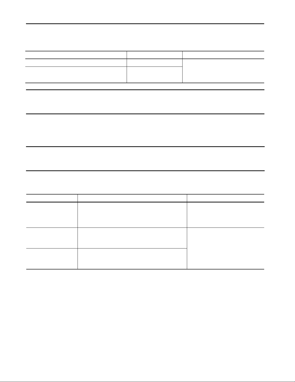
Chapter 6 Use the Secure Digital Card
5. Change the Load Mode properties according to your application
requirements.
If you want the controller to go to this mode after loading Then choose Menu Items
Program Program (remote only)
Run Run (remote only)
IMPOR TANT Safety Consideration
Rockwell Automation recommends that you use Program (Remote Only), when you set the Load Mode for a safety application
project.
6. According to your application requirements, set the Automatic
Firmware Update properties for I/O devices in the configuration tree of
the controller. The Automatic Firmware Update property is also referred
to as the Firmware Supervisor feature.
IMPOR TANT Safety Consideration
Some Safety I/O devices do not support the Firmware Supervisor feature. For example, Safety I/O devices on DeviceNet®
networks and POINT Guard I/O™ modules do not support the Firmware Supervisor feature.
This table describes the Automatic Firmware Update options for I/O
devices.
Setting Description Menu Items
Disable Disables any automatic firmware updates. This item only appears in the menu
Enable and Store Files to Image Enables automatic firmware updates for I/O devices in the configuration tree of
Disable and Delete Files from Image Disables automatic firmware updates for I/O devices in the configuration tree of
(1) The devices that are used with this option must support the revision of firmware being updated to.
when you initially save the image.
the controller. Saves I/O device firmware and controller firmware to the image.
Only I/O devices that are configured for Exact Match Keying will participate in
the Automatic Fir mware Update process.
the controller. Removes I/O device firmware from the image, but does not
remove controller firmware from image.This item only appears in the menu on
subsequent saves of the image.
(1)
7. Click Store.
8. Click Yes in the confirmation dialog box that appears.
96 Rockwell Automation Publication 1756-UM543K-EN-P - August 2020
Page 97

Use the Secure Digital Card Chapter 6
If you enabled Automatic Firmware Update, then a dialog box appears to
inform you which modules are not included in the Automatic Firmware
Update operation.
IMPORTANT Do not remove the SD card while the controller is reading from, or writing to,
the card. If you remove the card during either activity, the data on the card
or controller can become corrupt. Additionally, the controller firmware at
the time when the card is removed can become corrupted. Leave the card in
the controller until the OK status indicator turns solid green.
9. On the Automatic Firmware Update dialog box, click Yes.
The project is saved to the SD card as indicated by the controller status
indicators.
These indications show the store status
While the store is in progress, the following occurs:
• OK indicator is flashing green
• SD indicator is flashing green
• Saving…Do Not Remove SD Card is shown on the status display
• A dialog box in the Logix Designer application indicates that the store is in progress
• Controller Resets
• SAVE is shown on the status display
When the store is complete, the following occurs:
• The co ntroller resets.
IMPORTANT Allow the store to complete without interruption. If you interrupt the store,
data corruption or loss can occur.
Rockwell Automation Publication 1756-UM543K-EN-P - August 2020 97
Page 98

Chapter 6 Use the Secure Digital Card
Load from the SD Card
Applies to these controllers:
ControlLogix 5580
GuardLogix 5580
After you have set the communication path, are online with the controller, and
have changed the controller to Program mode, you can load a project to the
controller from the memory card.
IMPORTANT With the SD card and brand new, out-of-box controllers:
• If you insert an SD card with an image into a brand new, out-of-box
controller (firmware 1.x), then at power-up the controller automatically
updates the firmware up to the version of firmware that is stored on the
SD card. The update happens regardless of the Load Image setting in the
image on the SD card (User Initiated, On Power Up, or On Uninitialized
Memory).
• If the image was created with either On Power Up or On Uninitialized
Memory settings, then the controller both updates the firmware and
loads in the controller application.
You can load from an SD card to a controller in one of the following ways:
• Controller Power-up
• User-initiated Action
TIP You can always use the Logix Designer application to load the project.
Controller Power-up
This table shows what happens at power up when you insert an SD card that
contains an image into a controller.
Image Setting Controller is in out-of-box condition
User Initiated Loads Firmware Only
On Power Up Loads both Firmware and Application • Loads Firmware if there is a revision mismatch
On Uninitialized Memory Loads both Firmware and Application
(1) Indicates change in behavior from ControlLogix 5570 and older controllers.
(2) “Valid” includes the No Project condition.
(v1.x firmware)
(1)
Firmware > 1.x and internal non-volatile
memory is not valid
Does Nothing Does Nothing
• Loads Application
(1)
• Loads Firmware if there is a revision mismatch
• Loads Application
(2)
Firmware > 1.x and internal non-volatile
memory is valid
• Loads Firmware if there is a revision mismatch
• Loads Application
Does Nothing
(2)
98 Rockwell Automation Publication 1756-UM543K-EN-P - August 2020
Page 99

Use the Secure Digital Card Chapter 6
User-initiated Action
IMPORTANT For an out-of-box controller that uses firmware revision 1.xx, you must
manually update the controller to the required firmware revision before you
can load a project on the controller.
You must complete the following before you can upload a project to the
controller from the SD card when the controller is already powered-up:
• Make sure that the controller has a working firmware revision.
• Establish the communication path.
• Go online with the controller.
• Make sure that the controller is in Program mode.
To load a project to the controller from the memory card, complete these steps.
1. Open the Controller Properties, and click the Nonvolatile Memory tab.
2. On the Nonvolatile Memory tab, verify that the project listed next to
Name: is the project that you want to load.
TIP If no project is stored on the SD card, a message in the lower-left corner of the
Nonvolatile Memory tab indicates that an image (or project) is not available as
shown here.
TIP For information on how to change the project that is available to load from
nonvolatile memory, see the Logix 5000 Controllers Nonvolatile Memory
Programming Manual, publication 1756-PM017
.
3. Click Load/Store.
TIP If Load/Store is dimmed (unavailable), verify the following:
• You have specified the correct communication path and are online with
the controller.
• The SD card is installed.
• Verify that the controller is not in Run Mode.
Rockwell Automation Publication 1756-UM543K-EN-P - August 2020 99
Page 100

Chapter 6 Use the Secure Digital Card
4. Click Load.
After you click Load, the project loads to the controller as indicated by
the controller status indicators. A dialog box in the Logix Designer
application also indicates that the store is in progress.
Table 14 - These indications show the load status
Controller SD Indicator OK LED on Controller 4-Character Display Message
ControlLogix 5580 controller when restoring firmware or project Flashing Green Solid Red “LOAD”, then followed by “UPDT”
GuardLogix 5580 SIL 2 controller when restoring firmware or project Flashing Green Solid Red “LOAD”, then followed by “UPDT”
GuardLogix 5580 SIL 3 controller during primary controller firmware update Flashing Green Solid Green “Updating Firmware…Do Not Remove SD Card”
GuardLogix 5580 SIL 3 controller during Safety Partner firmware update Flashing Green Solid Green “Updating Firmware…Do Not Remove SD Card”
GuardLogix 5580 SIL 3 controller during when loading project Flashing Green Solid Green “Loading…Do Not Remove SD Card”
Other Secure Digital Card Tasks
Applies to these controllers:
ControlLogix 5580
GuardLogix 5580
IMPORTANT Let the load complete without interruption. If you interrupt the load, data
corruption or loss can occur.
5. When the load is complete, the controller reboots.
You can perform these tasks with the SD card:
• Change the image that is loaded from the card
• Check for a load that was completed
• Clear an image from the SD card
• Store an empty image
• Change load parameters
• Read/write application data to the card
• View safety-lock status and safety signatures on the Non-volatile
Memory tab - GuardLogix 5580 controllers only.
For more information to complete any of these tasks, see the Logix 5000
Controllers Memory Card Programming Manual, publication 1756-PM017
.
100 Rockwell Automation Publication 1756-UM543K-EN-P - August 2020
 Loading...