

Allen-Bradley ControlLogix 5580, CompactLogix 5380, Logix 5000, CompactLogix 5370, Compact GuardLogix 5370 Reference Manual
...
Reference Manual
Original Instructions
Replacement Guidelines: Logix 5000 Controllers
ControlLogix 5570 to ControlLogix 5580
GuardLogix 5570 to GuardLogix 5580
CompactLogix 5370 to CompactLogix 5380
Compact GuardLogix 5370 to Compact GuardLogix 5380
Important User Information
Read this document and the documents listed in the additional resources section about installation, configuration, and
operation of this equipment before you install, configure, operate, or maintain this product. Users are required to
familiarize themselves with installation and wiring instructions in addition to requirements of all applicable codes, laws,
and standards.
Activities including installation, adjustments, putting into service, use, assembly, disassembly, and maintenance are
required to be carried out by suitably trained personnel in accordance with applicable code of practice.
If this equipment is used in a manner not specified by the manufacturer, the protection provided by the equipment may
be impaired.
In no event will Rockwell Automation, Inc. be responsible or liable for indirect or consequential damages resulting from
the use or application of this equipment.
The examples and diagrams in this manual are included solely for illustrative purposes. Because of the many variables and
requirements associated with any particular installation, Rockwell Automation, Inc. cannot assume responsibility or
liability for actual use based on the examples and diagrams.
No patent liability is assumed by Rockwell Automation, Inc. with respect to use of information, circuits, equipment, or
software described in this manual.
Reproduction of the contents of this manual, in whole or in part, without written permission of Rockwell Automation,
Inc., is prohibited
Throughout this manual, when necessary, we use notes to make you aware of safety considerations.
WARNING: Identifies information about practices or circumstances that can cause an explosion in a hazardous
environment, which may lead to personal injury or death, property damage, or economic loss.
ATTENTION: Identifies information about practices or circumstances that can lead to personal injury or death, property
damage, or economic loss. Attentions help you identify a hazard, avoid a hazard, and recognize the consequence.
IMPORTANT Identifies information that is critical for successful application and understanding of the product.
Labels may also be on or inside the equipment to provide specific precautions.
SHOCK HAZARD: Labels may be on or inside the equipment, for example, a drive or motor, to alert people that dangerous
voltage may be present.
BURN HAZARD: Labels may be on or inside the equipment, for example, a drive or motor, to alert people that surfaces may
reach dangerous temperatures.
ARC FLASH HAZARD: Labels may be on or inside the equipment, for example, a motor control center, to alert people to
potential Arc Flash. Arc Flash will cause severe injury or death. Wear proper Personal Protective Equipment (PPE). Follow ALL
Regulatory requirements for safe work practices and for Personal Protective Equipment (PPE).

Table of Contents
Preface . . . . . . . . . . . . . . . . . . . . . . . . . . . . . . . . . . . . . . . . . . . . . . . . . . . . . . . .9
Summary of Changes . . . . . . . . . . . . . . . . . . . . . . . . . . . . . . . . . . . . . . . . . . . 9
Additional Resources . . . . . . . . . . . . . . . . . . . . . . . . . . . . . . . . . . . . . . . . . . . 9
Websites. . . . . . . . . . . . . . . . . . . . . . . . . . . . . . . . . . . . . . . . . . . . . . . . . . 10
Chapter 1
Before You Begin a Migration Considerations. . . . . . . . . . . . . . . . . . . . . . . . . . . . . . . . . . . . . . . . . . . . . . . . 12
New and Future Features . . . . . . . . . . . . . . . . . . . . . . . . . . . . . . . . . . . . . . 13
Integrated Architecture Tools . . . . . . . . . . . . . . . . . . . . . . . . . . . . . . . . . . 15
Migration Services. . . . . . . . . . . . . . . . . . . . . . . . . . . . . . . . . . . . . . . . . . . . . 15
Chapter 2
Replacement Considerations
with ControlLogix 5580 and
GuardLogix 5580 Systems
Minimum Requirements. . . . . . . . . . . . . . . . . . . . . . . . . . . . . . . . . . . . . . . 18
GuardLogix Controllers Minimum Requirements. . . . . . . . . . . . 18
Product Comparison . . . . . . . . . . . . . . . . . . . . . . . . . . . . . . . . . . . . . . . . . . 19
ControlLogix Controllers . . . . . . . . . . . . . . . . . . . . . . . . . . . . . . . . . . 19
GuardLogix Controllers. . . . . . . . . . . . . . . . . . . . . . . . . . . . . . . . . . . . 20
Controller Dimensions . . . . . . . . . . . . . . . . . . . . . . . . . . . . . . . . . . . . . . . . 22
ControlLogix 5570 Dimensions . . . . . . . . . . . . . . . . . . . . . . . . . . . . 22
ControlLogix 5580 Dimensions . . . . . . . . . . . . . . . . . . . . . . . . . . . . 22
GuardLogix 5570 Dimensions . . . . . . . . . . . . . . . . . . . . . . . . . . . . . . 23
GuardLogix 5580 Dimensions . . . . . . . . . . . . . . . . . . . . . . . . . . . . . . 23
Connectors and Status Indicators. . . . . . . . . . . . . . . . . . . . . . . . . . . . . . . 24
Project Size . . . . . . . . . . . . . . . . . . . . . . . . . . . . . . . . . . . . . . . . . . . . . . . . . . . 26
Configure the Controller . . . . . . . . . . . . . . . . . . . . . . . . . . . . . . . . . . . . . . 26
Connections Overview. . . . . . . . . . . . . . . . . . . . . . . . . . . . . . . . . . . . . 26
Nodes on an EtherNet/IP Network . . . . . . . . . . . . . . . . . . . . . . . . . 27
New Project Dialog Box. . . . . . . . . . . . . . . . . . . . . . . . . . . . . . . . . . . . 28
Controller Properties . . . . . . . . . . . . . . . . . . . . . . . . . . . . . . . . . . . . . . 29
Controller Reset . . . . . . . . . . . . . . . . . . . . . . . . . . . . . . . . . . . . . . . . . . . . . . 37
5570 Controllers . . . . . . . . . . . . . . . . . . . . . . . . . . . . . . . . . . . . . . . . . . 37
5580 Controllers . . . . . . . . . . . . . . . . . . . . . . . . . . . . . . . . . . . . . . . . . . 37
SD Card Behavior. . . . . . . . . . . . . . . . . . . . . . . . . . . . . . . . . . . . . . . . . . . . . 38
Communication Options . . . . . . . . . . . . . . . . . . . . . . . . . . . . . . . . . . . . . . 39
Communication Throughput . . . . . . . . . . . . . . . . . . . . . . . . . . . . . . 40
Download the Program to the Controller . . . . . . . . . . . . . . . . . . . . . . . 41
Build Button . . . . . . . . . . . . . . . . . . . . . . . . . . . . . . . . . . . . . . . . . . . . . . 41
Downloading Workflow Change . . . . . . . . . . . . . . . . . . . . . . . . . . . 42
Upload Fidelity Change. . . . . . . . . . . . . . . . . . . . . . . . . . . . . . . . . . . . 42
Thermal Monitoring and Thermal Fault Behavior . . . . . . . . . . . . . . . 43
Rockwell Automation Publication 1756-RM100F-EN-P - October 2018 3

Table of Contents
Chapter 3
Replacement Considerations
with CompactLogix and Compact
GuardLogix Systems
Minimum Requirements. . . . . . . . . . . . . . . . . . . . . . . . . . . . . . . . . . . . . . . 46
CompactLogix Controllers Minimum Requirements . . . . . . . . . 46
Compact GuardLogix Controllers Minimum Requirements . . 46
Product Comparison . . . . . . . . . . . . . . . . . . . . . . . . . . . . . . . . . . . . . . . . . . 47
CompactLogix Controllers Product Comparison . . . . . . . . . . . . 47
Compact GuardLogix Controllers Product Comparison . . . . . . 49
Controller Spacing . . . . . . . . . . . . . . . . . . . . . . . . . . . . . . . . . . . . . . . . . . . . 51
CompactLogix 5370 L3 and Compact GuardLogix 5370 L3
Spacing . . . . . . . . . . . . . . . . . . . . . . . . . . . . . . . . . . . . . . . . . . . . . . . . . . . 51
CompactLogix 5380 Spacing . . . . . . . . . . . . . . . . . . . . . . . . . . . . . . . 51
Compact GuardLogix 5380 Spacing. . . . . . . . . . . . . . . . . . . . . . . . . 52
Controller Dimensions . . . . . . . . . . . . . . . . . . . . . . . . . . . . . . . . . . . . . . . . 53
CompactLogix 5370 L3 Dimensions . . . . . . . . . . . . . . . . . . . . . . . . 53
CompactLogix 5380 Dimensions . . . . . . . . . . . . . . . . . . . . . . . . . . . 53
Compact GuardLogix 5370 Dimensions. . . . . . . . . . . . . . . . . . . . . 54
Compact GuardLogix 5380 Dimensions. . . . . . . . . . . . . . . . . . . . . 54
Connectors and Status Indicators. . . . . . . . . . . . . . . . . . . . . . . . . . . . . . . 55
Power the Controller . . . . . . . . . . . . . . . . . . . . . . . . . . . . . . . . . . . . . . . . . . 57
Project Size . . . . . . . . . . . . . . . . . . . . . . . . . . . . . . . . . . . . . . . . . . . . . . . . . . . 58
Configure the Controller . . . . . . . . . . . . . . . . . . . . . . . . . . . . . . . . . . . . . . 58
Connections Overview. . . . . . . . . . . . . . . . . . . . . . . . . . . . . . . . . . . . . 58
Nodes on an EtherNet/IP Network . . . . . . . . . . . . . . . . . . . . . . . . . 59
New Project Dialog Box. . . . . . . . . . . . . . . . . . . . . . . . . . . . . . . . . . . . 60
Controller Properties . . . . . . . . . . . . . . . . . . . . . . . . . . . . . . . . . . . . . . 61
Controller Reset Button . . . . . . . . . . . . . . . . . . . . . . . . . . . . . . . . . . . . . . . 67
SD Card Behavior. . . . . . . . . . . . . . . . . . . . . . . . . . . . . . . . . . . . . . . . . . . . . 68
Communication Options . . . . . . . . . . . . . . . . . . . . . . . . . . . . . . . . . . . . . . 69
Communication Throughput . . . . . . . . . . . . . . . . . . . . . . . . . . . . . . 70
EtherNet/IP Modes . . . . . . . . . . . . . . . . . . . . . . . . . . . . . . . . . . . . . . . . . . . 72
Dual-IP Mode. . . . . . . . . . . . . . . . . . . . . . . . . . . . . . . . . . . . . . . . . . . . . 72
Linear/DLR Mode . . . . . . . . . . . . . . . . . . . . . . . . . . . . . . . . . . . . . . . . 73
Use I/O Modules in CompactLogix Systems . . . . . . . . . . . . . . . . . . . . 74
CompactLogix 5370 L3 System. . . . . . . . . . . . . . . . . . . . . . . . . . . . . 75
CompactLogix 5380 System. . . . . . . . . . . . . . . . . . . . . . . . . . . . . . . . 75
Local I/O Module Performance. . . . . . . . . . . . . . . . . . . . . . . . . . . . . 76
Event Task Triggers . . . . . . . . . . . . . . . . . . . . . . . . . . . . . . . . . . . . . . . 77
Scheduled Outputs . . . . . . . . . . . . . . . . . . . . . . . . . . . . . . . . . . . . . . . . 78
Download the Program to the Controller . . . . . . . . . . . . . . . . . . . . . . . 79
Build Button . . . . . . . . . . . . . . . . . . . . . . . . . . . . . . . . . . . . . . . . . . . . . . 79
Downloading Workflow Change . . . . . . . . . . . . . . . . . . . . . . . . . . . 80
Upload Fidelity Change. . . . . . . . . . . . . . . . . . . . . . . . . . . . . . . . . . . . 80
Thermal Monitoring and Thermal Fault Behavior . . . . . . . . . . . . . . . 81
4 Rockwell Automation Publication 1756-RM100F-EN-P - October 2018

Chapter 4
Table of Contents
Replacement Considerations
with Safety Applications
Perform Risk Assessment . . . . . . . . . . . . . . . . . . . . . . . . . . . . . . . . . . . . . . 83
Applications with
1734-AENTR Series A Modules. . . . . . . . . . . . . . . . . . . . . . . . . . . . . . . . 84
Safety Signature . . . . . . . . . . . . . . . . . . . . . . . . . . . . . . . . . . . . . . . . . . . . . . . 84
GSV of Safety Attributes . . . . . . . . . . . . . . . . . . . . . . . . . . . . . . . . . . . 85
Safety Network Number . . . . . . . . . . . . . . . . . . . . . . . . . . . . . . . . . . . . . . . 86
Produce/Consume Safety Tags . . . . . . . . . . . . . . . . . . . . . . . . . . . . . . . . . 87
Safety Application Conversion . . . . . . . . . . . . . . . . . . . . . . . . . . . . . . . . . 88
Exporting and importing Safety Add-on Instructions . . . . . . . . . 88
Convert a Safety Application . . . . . . . . . . . . . . . . . . . . . . . . . . . . . . . 89
Replace Producer Controller . . . . . . . . . . . . . . . . . . . . . . . . . . . . . . . . . . . 94
Chapter 5
Standard Application Conversion Converting Logix Designer Projects. . . . . . . . . . . . . . . . . . . . . . . . . . . . . 95
Produce and Consume Tags. . . . . . . . . . . . . . . . . . . . . . . . . . . . . . . . . . . . 96
RPI of Multicast Tags. . . . . . . . . . . . . . . . . . . . . . . . . . . . . . . . . . . . . . 96
Data Structures. . . . . . . . . . . . . . . . . . . . . . . . . . . . . . . . . . . . . . . . . . . . 97
Late Binding of I/O Data . . . . . . . . . . . . . . . . . . . . . . . . . . . . . . . . . . . . . 103
Standard Native I/O Data Types and Tags . . . . . . . . . . . . . . . . . 103
I/O Data Manipulation. . . . . . . . . . . . . . . . . . . . . . . . . . . . . . . . . . . . . . . 104
Motion Applications . . . . . . . . . . . . . . . . . . . . . . . . . . . . . . . . . . . . . . . . . 105
ControlLogix 5580 and GuardLogix 5580 Controllers . . . . . . 105
CompactLogix 5380 and Compact GuardLogix 5380
Controllers . . . . . . . . . . . . . . . . . . . . . . . . . . . . . . . . . . . . . . . . . . . . . . 106
Axis Position References in Move Instructions . . . . . . . . . . . . . . 107
Pending Edits . . . . . . . . . . . . . . . . . . . . . . . . . . . . . . . . . . . . . . . . . . . . . . . . 107
AXIS_CIP_Drive Data Type . . . . . . . . . . . . . . . . . . . . . . . . . . . . . . . . . 108
Chapter 6
Instruction Execution Math-related Instructions. . . . . . . . . . . . . . . . . . . . . . . . . . . . . . . . . . . . . 110
TRN Instruction Changes . . . . . . . . . . . . . . . . . . . . . . . . . . . . . . . . 110
Improved Math Instruction Accuracy . . . . . . . . . . . . . . . . . . . . . . 111
SQR/SQRT Adjustment. . . . . . . . . . . . . . . . . . . . . . . . . . . . . . . . . . 111
X Mod 0 . . . . . . . . . . . . . . . . . . . . . . . . . . . . . . . . . . . . . . . . . . . . . . . . . 112
AND, NOT, OR, and XOR Support for REAL. . . . . . . . . . . . . 112
Floating Point Literals . . . . . . . . . . . . . . . . . . . . . . . . . . . . . . . . . . . . 113
XPY Instruction. . . . . . . . . . . . . . . . . . . . . . . . . . . . . . . . . . . . . . . . . . 115
0.0 div 0.0. . . . . . . . . . . . . . . . . . . . . . . . . . . . . . . . . . . . . . . . . . . . . . . . 115
Structural Changes to Execution . . . . . . . . . . . . . . . . . . . . . . . . . . . . . . 116
JSR Nesting Level Limit. . . . . . . . . . . . . . . . . . . . . . . . . . . . . . . . . . . 116
Max Number of Inputs or Outputs for a Program JSR/RET . 117
Max Number of InOut Parameters for an
Add-On Instruction . . . . . . . . . . . . . . . . . . . . . . . . . . . . . . . . . . . . . . 118
Jump to Label Must Be Present . . . . . . . . . . . . . . . . . . . . . . . . . . . . 119
MCR Placement . . . . . . . . . . . . . . . . . . . . . . . . . . . . . . . . . . . . . . . . . 120
Rockwell Automation Publication 1756-RM100F-EN-P - October 2018 5

Table of Contents
Data Alignment and Memory Allocation Rules for
User-defined Data Types (UDTs) That Contain LINTs. . . . . 120
Instruction Error and Fault Changes. . . . . . . . . . . . . . . . . . . . . . . . . . . 122
Subscript Expressions . . . . . . . . . . . . . . . . . . . . . . . . . . . . . . . . . . . . . 123
TRN Operator and Math Status Flags. . . . . . . . . . . . . . . . . . . . . . 124
Math Status Flags are Valid Only in One Rung. . . . . . . . . . . . . . 125
AVE and STD Instruction Accuracy . . . . . . . . . . . . . . . . . . . . . . . 126
BTD, FAL, FSC, and CMP No Longer Generate
Math Status . . . . . . . . . . . . . . . . . . . . . . . . . . . . . . . . . . . . . . . . . . . . . . 126
Math Status Flags Not Permitted in Structured Text . . . . . . . . 127
Minor Fault on Overflow . . . . . . . . . . . . . . . . . . . . . . . . . . . . . . . . . 128
Manually Set Math Overflow . . . . . . . . . . . . . . . . . . . . . . . . . . . . . . 129
TOD Instruction Flags and Math Status Flags . . . . . . . . . . . . . . 130
Add-On Instructions Do Not Propagate Math Status Flags . . 130
Subroutines Do Not Affect Math Status Flags . . . . . . . . . . . . . . 131
Carry Flag . . . . . . . . . . . . . . . . . . . . . . . . . . . . . . . . . . . . . . . . . . . . . . . 132
Store NAN in an Integer . . . . . . . . . . . . . . . . . . . . . . . . . . . . . . . . . . 133
Compare NAN Values. . . . . . . . . . . . . . . . . . . . . . . . . . . . . . . . . . . . 133
Operand Changes . . . . . . . . . . . . . . . . . . . . . . . . . . . . . . . . . . . . . . . . . . . . 134
Converting +/- Infinity . . . . . . . . . . . . . . . . . . . . . . . . . . . . . . . . . . . 134
Copy/File Instructions . . . . . . . . . . . . . . . . . . . . . . . . . . . . . . . . . . . . . . . 135
COP and CPS Into Structures . . . . . . . . . . . . . . . . . . . . . . . . . . . . 135
JSR and RET Parameters Passing Into Structures. . . . . . . . . . . . 136
JSR passing Atomic Data type into an Array or Structure . . . . 137
Instructions That Operate On Arrays . . . . . . . . . . . . . . . . . . . . . . 139
GSV/SSV Instructions. . . . . . . . . . . . . . . . . . . . . . . . . . . . . . . . . . . . . . . . 139
MCT/MCTP Instructions. . . . . . . . . . . . . . . . . . . . . . . . . . . . . . . . . . . . 140
Chapter 7
Diagnostics and Status Indicators
with ControlLogix Systems
6 Rockwell Automation Publication 1756-RM100F-EN-P - October 2018
Controller Status Display and Indicators . . . . . . . . . . . . . . . . . . . . . . . 141
4-Character Display . . . . . . . . . . . . . . . . . . . . . . . . . . . . . . . . . . . . . . 141
Status Indicators. . . . . . . . . . . . . . . . . . . . . . . . . . . . . . . . . . . . . . . . . . 142
Ethernet Indicators . . . . . . . . . . . . . . . . . . . . . . . . . . . . . . . . . . . . . . . 142
Controller Web Pages . . . . . . . . . . . . . . . . . . . . . . . . . . . . . . . . . . . . . . . . 143
Home Web Page . . . . . . . . . . . . . . . . . . . . . . . . . . . . . . . . . . . . . . . . . 143
Tasks Web Page . . . . . . . . . . . . . . . . . . . . . . . . . . . . . . . . . . . . . . . . . . 144
Diagnostics Web Pages. . . . . . . . . . . . . . . . . . . . . . . . . . . . . . . . . . . . 145
Advanced Diagnostics Web Pages. . . . . . . . . . . . . . . . . . . . . . . . . . 146
Browse Chassis Web Page . . . . . . . . . . . . . . . . . . . . . . . . . . . . . . . . . 147

Chapter 8
Table of Contents
Diagnostics and Status Indicators
with CompactLogix Systems
Controller Status Display and Indicators . . . . . . . . . . . . . . . . . . . . . . . 150
4-Character Display . . . . . . . . . . . . . . . . . . . . . . . . . . . . . . . . . . . . . . 150
Controller Status Indicators . . . . . . . . . . . . . . . . . . . . . . . . . . . . . . . 152
EtherNet/IP Status Indicators . . . . . . . . . . . . . . . . . . . . . . . . . . . . . 153
Power Status Indicators . . . . . . . . . . . . . . . . . . . . . . . . . . . . . . . . . . . 154
Controller Web Pages . . . . . . . . . . . . . . . . . . . . . . . . . . . . . . . . . . . . . . . . 155
Differences Between 5380 and 5370 Controllers . . . . . . . . . . . . 155
EtherNet/IP Mode Affect on 5380 Controller Web Pages . . . 155
Home Web Page . . . . . . . . . . . . . . . . . . . . . . . . . . . . . . . . . . . . . . . . . 156
Tasks Web Page . . . . . . . . . . . . . . . . . . . . . . . . . . . . . . . . . . . . . . . . . . 157
Diagnostics Web Pages. . . . . . . . . . . . . . . . . . . . . . . . . . . . . . . . . . . . 158
Ethernet Port A1/A2 Web Pages . . . . . . . . . . . . . . . . . . . . . . . . . . 159
Advanced Diagnostics Web Pages. . . . . . . . . . . . . . . . . . . . . . . . . . 160
Browse Chassis Web Page . . . . . . . . . . . . . . . . . . . . . . . . . . . . . . . . . 162
Index . . . . . . . . . . . . . . . . . . . . . . . . . . . . . . . . . . . . . . . . . . . . . . . . . . . . . . 163
Rockwell Automation Publication 1756-RM100F-EN-P - October 2018 7

Table of Contents
Notes:
8 Rockwell Automation Publication 1756-RM100F-EN-P - October 2018
Preface
This manual is intended to offer guidelines when you replace the following:
• ControlLogix® 5570 controller with a ControlLogix® 5580 controller.
Guidelines that reference a ControlLogix 5570 controller also apply to a
ControlLogix 5560 controller.
• CompactLogix™ 5370 L3 controller with a CompactLogix 5380
controller
• GuardLogix® 5560 or GuardLogix 5570 controller with a GuardLogix
5580 controller.
• Compact GuardLogix 5370 L3 controller with a Compact GuardLogix
5380 controller
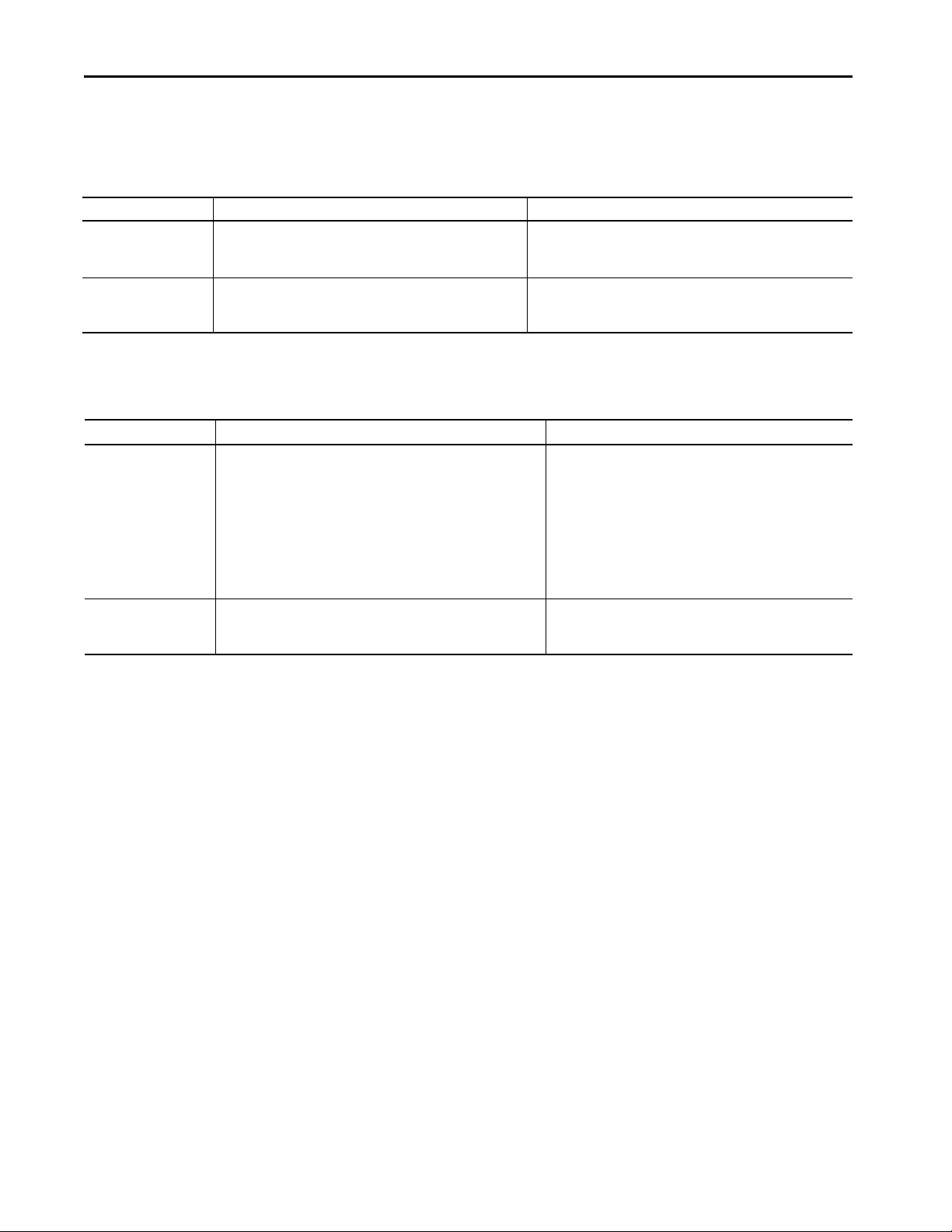
Summary of Changes
This manual contains new and updated information as indicated in the
following table.
Top ic Pa ge
Added information regarding GuardLogix 5580 and Compact GuardLogix 5380
controllers.
Added Chapter 4: Replacement Considerations with Safety Applications 83
Added information on the AXIS_CIP_Drive Data Type for Studio 5000 Logix Designer®
V31.00.00
Additional Resources
These resources contain information about related products from
Rockwell Automation.
These documents contain more information about Logix 5000™ controllers.
Table 1 - Additional Resources
Resource Description
• EtherNet/IP™ Communication Modules in Logix 5000™ Control Systems, publication ENET-UM004
• EtherNet/IP Network Configuration User Manual, publication ENET-UM001
• ControlNet® Network Configuration User Manual, publication CNET-UM001
• DeviceNet® Network Configuration User Manual, publication DNET-UM004
• Logix 5000 Controllers Common Procedures Programming Manual, publication 1756-PM001
• Logix Controllers Instructions Reference Manual, publication 1756-RM009
• Logix 5000 Controllers Advanced Process Control and Drives Instructions Reference Manual, publication 1756-RM006
• Logix 5000 Controllers Motion Instructions Reference Manual, publication MOTION-RM002
• Logix 5000 Controllers Import/Export Reference Manual, publication 1756-RM084
Networks
Logix 5000 Software and Programming
Through out
108
Rockwell Automation Publication 1756-RM100F-EN-P - October 2018 9
Preface
Table 1 - Additional Resources
Resource Description
• 1756 ControlLogix Controllers Technical Data, publication 1756-TD001
• ControlLogix 5580 Controllers Product Information, publication 1756-PC405
• ControlLogix 5580 and GuardLogix 5580 Controllers User Manual, publication 1756-UM543
• ControlLogix Chassis and Power Supply, publication 1756-IN005
• 1756 ControlLogix Chassis Specifications Technical Data, publication 1756-TD006
• CompactLogix 5380 Controller Specifications Technical Data, publication 5069-TD002
• CompactLogix 5380 Controllers Installation Instructions, publication 5069-IN013
• CompactLogix 5380 and Compact GuardLogix 5380 Controllers User Manual, publication 5069-UM001
• CompactLogix 5370 Controllers User Manual, publication 1769-UM021
• CompactLogix 5370 L3 Controllers Quick Start, publication IASIMP-QS023
• CompactLogix Performance and Capacity Quick Reference, publication IASIMP-QR007
ControlLogix Controllers, Chassis, and Power Supply
CompactLogix Controllers
You can view or download publications at
http://www.rockwellautomation.com/literature/
To order paper copies of technical documentation, contact your local
Allen-Bradley distributor or Rockwell Automation sales representative.
.
Websites
Resource Description
https://ab.rockwellautomation.com/ Product Selection Information
Product Compatibility and Download Center (PCDC) Product-relate d downloads including firmware, release
http://samplecode.rockwellautomation.com Studio 5000 Logix Designer Sample Code
notes, associated software, drivers, tools, and utilities
(produc t serial nu mber required)
10 Rockwell Automation Publication 1756-RM100F-EN-P - October 2018
Chapter 1
Before You Begin a Migration
Topic Page
Considerations 12
New and Future Features 13
Integrated Architecture Tools 15
Migration Services 15
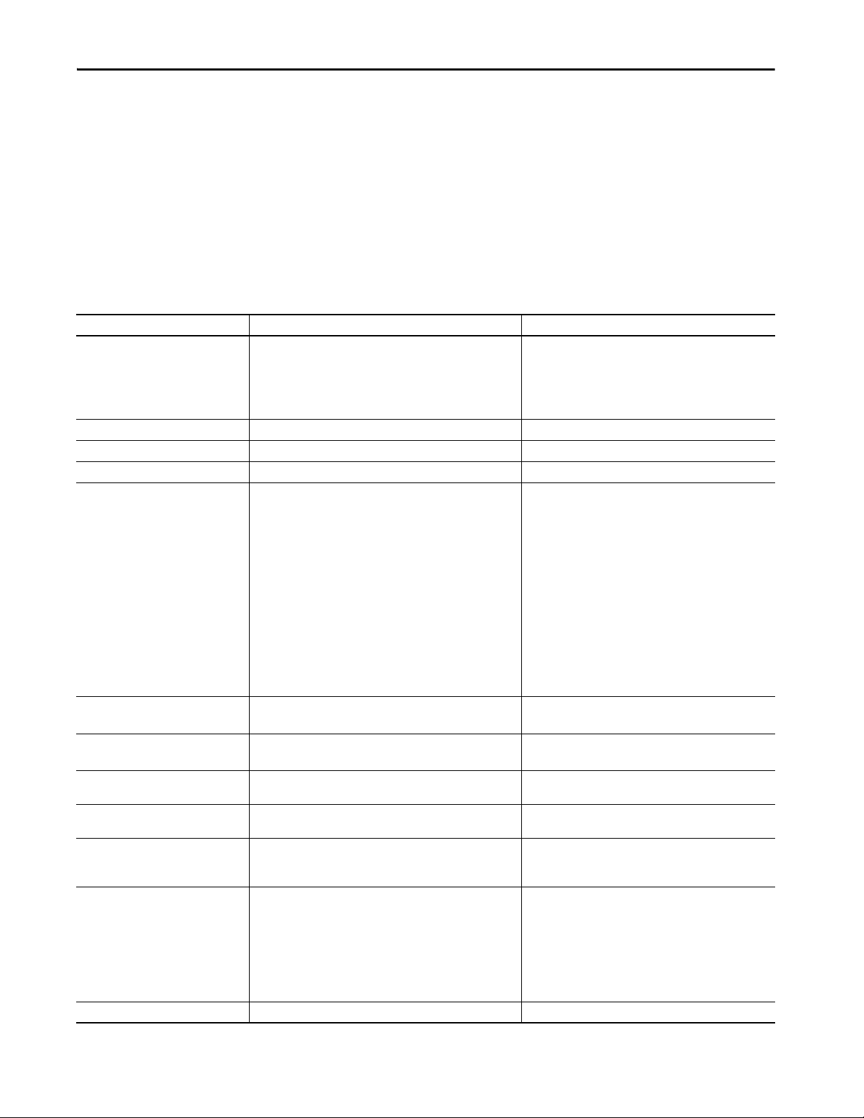
This publication features these controllers, and where applicable, the
controllers are known as:
Controller Family Includes these controllers
5580 controllers ControlLogix® 5580 and GuardLogix® 5580 controllers
5380 controllers CompactLogix™ 5380 and Compact GuardLogix 5380 controllers
5570 controllers ControlLogix 5570 and GuardLogix 5570 controllers
5370 controllers CompactLogix 5370 and Compact GuardLogix 5370 controllers
This publication provides a reference to controller capabilities and how the
5580/5380 controller capabilities differ from the 5570/5370 controllers.
IMPORTANT Any user or third-party developer of communications software to a
ControlLogix or CompactLogix controller must fully follow the Logix 5000™
Data Access Programming Manual, 1756-PM020
.
Beginning with Logix controller families 5380 and 5580, the full
implementation and enforcement of the CIP™ specification standard for
ANSI Extended Symbolic 0x91 is required, as documented in the above
referenced publication and the ODVA CIP specification.
Any custom or 3rd party communications software, which previously only
supported ANSI Extended Symbolic 0x61, will need to be updated to
communicate to these new controllers.
Previous Logix controller families CompactLogix L1, L2, L3, 5370 and
ControlLogix 5550, 5560, 5570 continue to support both the 0x91 CIP
Standard and the older, no longer in use, 0x61.
Rockwell Automation Publication 1756-RM100F-EN-P - October 2018 11

Chapter 1 Before You Begin a Migration
Considerations
Throughout this manual, the following apply:
• Guidelines that reference a ControlLogix 5570 controller also apply to a
ControlLogix 5560 controller.
• There are references to controller project versions. Controller project
versions 20 or earlier are created in RSLogix 5000® software. Controller
project versions 21 or later are created in the Studio 5000 Logix
Designer® environment, referred to as the Logix Designer application
throughout this publication.
• Not all controllers are available with all versions of RSLogix 5000
software or the Logix Designer application.
For example, CompactLogix 5370 L3 controllers are available in
RSLogix 5000 software, version 20 and the Logix Designer application,
version 21 or later.
• Unless otherwise indicated, the graphics that are used throughout
manual are the same for 5380 and 5580 controllers.
Product compatibility information and release notes are available online
within the Product Compatibility and Download Center at
http://www.rockwellautomation.com/rockwellautomation/support/
pcdc.page.
12 Rockwell Automation Publication 1756-RM100F-EN-P - October 2018
Before You Begin a Migration Chapter 1
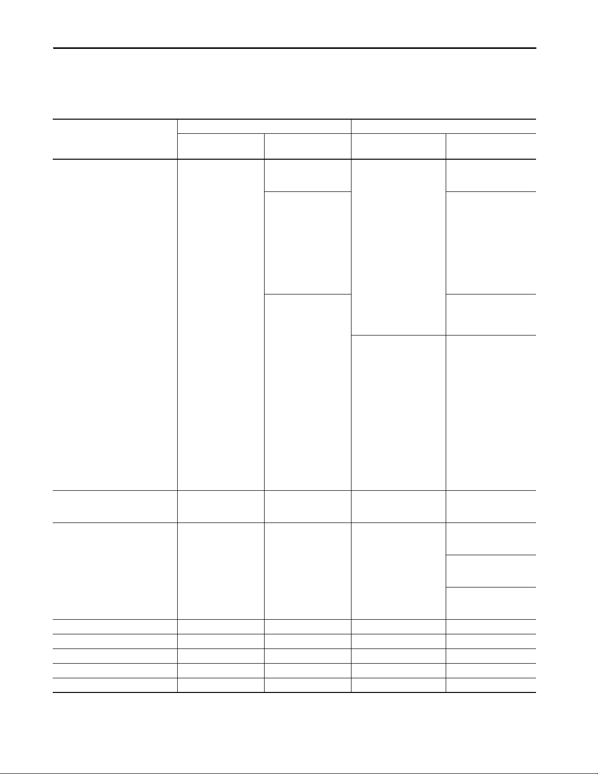
New and Future Features
The following table indicates the Studio 5000 Logix Designer environment
version in which product features are available.
Table 2 - New and Future Features
Feature ControlLogix Controllers CompactLogix Controllers
ControlLogix 5570
GuardLogix 5570
Hardware support No new controllers in
1 Gbps Ethernet port Not applicable Single embedded Ethernet
EtherNet/IP™ modes:
• Dual-IP mode
•DLR/Linear mode
Instruction-based alarms (ALMA, ALMD) All versions Version 29 or later All versions Version 29 or later
Tag-based Alarms Not applicable Version 31 or later Not applicable Version 31 or later
Integrated Motion on EtherNet/IP All versions Version 28 or later All versions
SERCOS motion All versions Version 31 or later Not supported Not supported
Analog motion All versions Version 31 or later Not supported Future
versions 28, 29, or 30
Not applicable Not supported DLR/Linear mode in all versions
ControlLogix 5580
GuardLogix 5580
New controllers in version 28:
• 1756-L83E
• 1756-L85E
New controllers in version 29:
• 1756-L81E
• 1756-L82E
• 1756-L84E
New controllers in version 31:
• 1756-L81ES
• 1756-L82ES
• 1756-L83ES
• 1756-L84ES
port that supports up to 1
Gbps communication rate
CompactLogix 5370 L3
Compact GuardLogix 5370 L3
New controllers in version 28:
• 1769-L30ERMS
• 1769-L33ERMS
• 1769-L36ERMS
New controllers in version 31:
• 1769-L37ERM
• 1769-L37ERMS
• 1769-L38ERM
• 1769-L38ERMS
• 1769-L38ERMO
• 1769-L38ERMOS
Not supported Dual, embedded Ethernet ports
that support CompactLogix 5370
L3 controllers
(3)
CompactLogix 5380
Compact GuardLogix 5380
New controllers in version 28:
• 5069-L320ER
• 5069-L340ERM
New controllers in version 29:
• 5069-L306ER,
5069-L306ERM
• 5069-L310ER,
5069-L310ER-NSE,
5069-L310ERM
• 5069-L320ERM
• 5069-L330ER,
5069-L330ERM
• 5069-L340ER
• 5069-L350ER
New controllers in version 30:
• 5069-L350ERM
• 5069-L380ERM
• 5069-L3100ERM
New controllers in version 31:
• 5069-L306ERS2
• 5069-L306ERMS2
• 5069-L310ERS2
• 5069-L310ERMS2
• 5069-L320ERS2
• 5069-L320ERMS2
• 5069-L330ERS2
• 5069-L330ERMS2
• 5069-L340ERS2
• 5069-L340ERMS2
• 5069-L350ERS2
• 5069-L350ERMS2
• 5069-L380ERS2
• 5069-L380ERMS2
• 5069-L3100ERS2
• 5069-L3100ERMS2
that each support up to 1 Gbps
communication rate
CompactLogix 5380 Controllers
Version 28 or later DLR/Linear mode
CompactLogix 5380 Controllers
Version 29 or later Dual-IP mode and DLR/Linear
Compact GuardLogix 5380
Controllers Version 31or later Dual-IP mode and DLR/Linear
Vers ion 2 8 or la ter
(3)
Rockwell Automation Publication 1756-RM100F-EN-P - October 2018 13
Chapter 1 Before You Begin a Migration
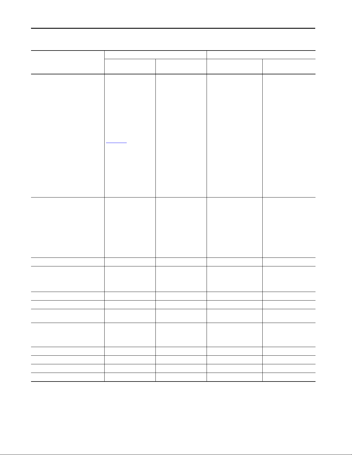
Table 2 - New and Future Features
Feature ControlLogix Controllers CompactLogix Controllers
ControlLogix 5570
GuardLogix 5570
Integrated safety SIL 2/PLd Version 28 or later for
ControlLogix 5570 controllers
only, along with components
of the ControlLogix system
that are type-approved and
certified for use in SIL 2
applications, according to IEC
(2)
61508.
For more information, see the
Using ControlLogix in SIL 2
Applications Safety Reference
Manual, publication
1756-RM001.
Integrated safety SIL 3/PLe Version 28 or later with these
GuardLogix 5570 controllers
and safety partner:
• 1756-L71S and
1756-L7SP
• 1756-L72S and
1756-L7SP
• 1756-L73S and
1756-L7SP
PanelView™ 5000 graphic terminal support Version 27 or later Version 29 or later Version 27 or later Version 29 or later
Redundancy ControlLogix 5570 controllers
- Versions 19, 20, and 24
ControlLogix 5560 controllers
- Versions 19 and 20
PhaseManager™ All versions Future All versions Future
SequenceManager™ Version 28 or later Future Version 28 or later Future
Drive-based CIP Safety stopping functions
(1)
, monitored/timed SS1)
(STO
Controller-based CIP Safety stopping and
Version 30 or later Version 31 or later Version 30 or later Version 31 or later
Not applicable Version 31 or later Not applicable Version 31 or later
monitoring functions
(SS1, SS2, SOS, SLS, SLP, SDI)
Secured Data Exchange Version 30 or later Future Version 30 or later Future
Controller-based Audit Log Version 30 or later Future Version 30 or later Future
Component Change Detection Version 30 or later Future Version 30 or later Future
Emulate All versions Future All versions Future
(1) Only the GuardLogix 5570, GuardLogix 5580, Compact GuardLogix 5370, and Compact GuardLogix 5380 controllers support the CIP Safety™ protocol that is needed for the Safe To rque Off (STO)
function.
(2) This type of SIL 2 application is not supported by ControlLogix 5580 controllers.
(3) Not all CompactLogix 5370 L3 or CompactLogix 5380 controllers support Integrated Motion on an EtherNet/IP network.
ControlLogix 5580
GuardLogix 5580
Version 31 or later with these
GuardLogix 5580 controllers:
• 1756-L81ES
• 1756-L82ES
• 1756-L83ES
• 1756-L84ES
Achieve SIL 2/PLd with the
use of a primary safety
controller, the safety task, and
safety I/O.
CompactLogix 5370 L3
Compact GuardLogix 5370 L3
CompactLogix 5380
Compact GuardLogix 5380
Not supported Version 31 or later with these
Compact GuardLogix 5380
controllers:
• 5069-L306ERS2
• 5069-L306ERMS2
• 5069-L310ERS2
• 5069-L310ERMS2
• 5069-L320ERS2
• 5069-L320ERMS2
• 5069-L330ERS2
• 5069-L330ERMS2
• 5069-L340ERS2
• 5069-L340ERMS2
• 5069-L350ERS2
• 5069-L350ERMS2
• 5069-L380ERS2
• 5069-L380ERMS2
• 5069-L3100ERS2
• 5069-L3100ERMS2
Achieve SIL 2/PLd with the use
of the SIL2/PLd capable safety
controller, the safety task, and
safety I/O.
Version 31 or later with these
GuardLogix 5580 controllers
and safety partner:
• 1756-L81ES
• 1756-L82ES
• 1756-L83ES
• 1756-L84ES
• 1756-L8SP
Version 28 or later with these
Compact GuardLogix 5370 L3
controllers:
• 1769-L30ERMS
• 1769-L33ERMS
• 1769-L36ERMS
• 1769-L36ERMOS
• 1769-L37ERMS
Future
• 1769-L37ERMOS
• 1769-L38ERMS
• 1769-L38ERMOS
Future Not supported Not supported
14 Rockwell Automation Publication 1756-RM100F-EN-P - October 2018

Before You Begin a Migration Chapter 1
Integrated Architecture Tools
Migration Services
The Integrated Architecture® system can help you plan and configure a system,
and migrate system architectures. For more information, go to:
http://www.rockwellautomation.com/rockwellautomation/productstechnologies/integrated-architecture/tools/overview.page?
Rockwell Automation can help you in the following ways:
• To get the most out of your current equipment.
• To determine your next steps.
• To plan for the transition to newer technology.
You can migrate all at once or use our unique, phased approach. The phased
approach helps you minimize the costs, risks, and complexities that are present
when you manage legacy products and systems. Regardless of the migration
approach that you take, Rockwell Automation has the tools and the experience
to guide you through the transition.
For more information, see Migration Solutions Brochure,
publication MIGRAT-BR002
.
Rockwell Automation Publication 1756-RM100F-EN-P - October 2018 15

Chapter 1 Before You Begin a Migration
Notes:
16 Rockwell Automation Publication 1756-RM100F-EN-P - October 2018

Chapter 2
Replacement Considerations with ControlLogix
5580 and GuardLogix 5580 Systems
Topic Page
Minimum Requirements 18
Product Comparison 19
Controller Dimensions 22
Connectors and Status Indicators 24
Project Size 26
Configure the Controller 26
Controller Res et 37
SD Card Behavior 38
Communication Options 39
Download the Program to the Controller 41
Thermal Monitoring and Thermal Fault Behavior 43
This chapter describes features and functions that are associated with the
ControlLogix® 5580 and GuardLogix® 5580 controllers.
This chapter features these controllers, and where applicable, the controllers
are known as:
Controller Family Includes these controllers
5580 controllers ControlLogix 5580 and GuardLogix 5580 controllers
5570 controllers ControlLogix 5570 and GuardLogix 5570 controllers
It is not an exhaustive list of the features and functions available with the
controllers. Instead, the list indicates what is new or changed in the controller
at this release:
• Embedded 10/100/1000 Mbps Ethernet port
• Higher performance and capacity including :
– Motion Processing: 256 total axes
– Total I/O packets processing: 128,000 pps
– 320 unconnected message buffers
– 256 simultaneous cached message instructions in the running state
– Support for up to 300 EtherNet/IP™ nodes
• Support for Compact 5000™ I/O over an EtherNet/IP network
• Change Ethernet port speed without a module reset
Rockwell Automation Publication 1756-RM100F-EN-P - October 2018 17
Chapter 2 Replacement Considerations with ControlLogix 5580 and GuardLogix 5580 Systems
Minimum Requirements
The 5580 controllers have these minimum requirements.
ControlLogix Controllers Minimum Requirements
Requirement, Minimum ControlLogix 5570 Controller ControlLogix 5580 Controller
Chassis 1756-A4, 1756-A7, 1756-A10, 1756-A13, 1756-A17
Series A, Series B, and Series C
Programming Software Studio 5000 Automation Engineering & Design Environment®,
Version 21.00.00 or later
RSLogix 5000® Software Version 20.00.00 or later
1756-A4, 1756-A7, 1756-A10, 1756-A13, 1756-A17
0 °C < Ta < +60 °C (+32 °F < Ta < +140 °F) for Series C Chassis
0 °C < Ta < +50 °C (+32 °F < Ta < +122 °F) for Series B Chassis
Studio 5000 Logix Designer® Application Version 28.00.00 or later
GuardLogix Controllers Minimum Requirements
Requirement, Minimum GuardLogix 5570 Controller GuardLogix 5580 Controller
Chassis 1756-A4, 1756-A7, 1756-A10, 1756-A13, 1756-A17
Series A, Series B, and Series C
Programming Software Studio 5000 Automation Engineering & Design Environment,
Version 21.00.00 or later
RSLogix 5000 Software Version 20.00.00 or later
1756-A4, 1756-A7, 1756-A10, 1756-A13, 1756-A17
Operating in SIL 2/PL d Configuration:
0 °C < Ta < +60 °C (+32 °F < Ta < +140 °F) for Series C Chassis
Note: If operating above +55 °C (+131 °F), modules greater than
6.2 W shall not be installed in slots adjacent to the controller.
Operating in SIL 3/PL e Configuration:
0 °C < Ta < +60 °C (+32 °F < Ta < +140 °F) for Series C Chassis
0 °C < Ta < +50 °C (+32 °F < Ta < +122 °F) for Series B Chassis
Studio 5000 Logix Designer Application Version 31.00.00 or later
18 Rockwell Automation Publication 1756-RM100F-EN-P - October 2018
Replacement Considerations with ControlLogix 5580 and GuardLogix 5580 Systems Chapter 2
Product Comparison
This section compares:
• ControlLogix 5580 controllers to ControlLogix 5570 controllers
• GuardLogix 5580 controllers to GuardLogix 5570 controllers
ControlLogix Controllers
The ControlLogix 5580 controllers operate similarly to the
ControlLogix 5570 controllers, with these differences.
Table 3 - Technical Specifications
Attribute ControlLogix 5570 Controller ControlLogix 5580 Controller
Memory 4…32 MB user memory 1756-L81E: 3 MB
1756-L82E: 5 MB
1756-L83E: 10 MB
1756-L84E: 20 MB
1756-L85E: 40 MB
I/O Memory 0.98 MB Not applicable
Compact 5000 I/O modules supported Not supported Full support
Embedded Ethernet Not applicable 10/100/1000 Mbps
Ethernet nodes Controller connections: a total of 500 connections used for Ethernet
I/O and Ethernet Messaging.
Logix Designer application, version 28:
• 1756-L83E: 100 EtherNet/IP nodes, max
• 1756-L85E: 300 EtherNet/IP nodes, max
Logix Designer application, version 29:
• 1756-L81E: 60 EtherNet/IP nodes, max
• 1756-L82E: 80 EtherNet/IP nodes, max
• 1756-L83E: 100 EtherNet/IP nodes, max
• 1756-L84E: 150 EtherNet/IP nodes, max
• 1756-L85E: 300 EtherNet/IP nodes, max
(2)
Logix Designer application, version 30 or later:
• 1756-L81E: 100 EtherNet/IP nodes, max
• 1756-L82E: 175 EtherNet/IP nodes, max
• 1756-L83E: 250EtherNet/IP nodes, max
• 1756-L84E: 250 EtherNet/IP nodes, max
• 1756-L85E: 300 EtherNet/IP nodes, max
Ethernet performance Not applicable Ethernet I/O (Class 0/1): 128,000 packets per second
Ethernet Messaging (Class 3): 2000 messages per second
Unconnected message buffers 20 outgoing buffers, configurable to 40
4 incoming buffers
Concurrent cached message instructions
in the running state
HMI and Messaging (Class 3) Drawn from the 500 total connections supported by the controller. 512 dedicated messages (256 incoming messages and 256
Integrated motion • SERCOS interface
Motion axes 128, any combination of these supported axis types:
Axes/ms over backplane 8 19
32, drawn from the 500 total connections supported by the
controller.
• Analog options (encoder input, LDT input, SSI input)
•EtherNet/IP network
• CIP™
• Consumed
• Virtual
• Position loop drives
•Servo
•Servo drive
• Generic
320 - Any combination of outgoing or incoming unconnected
buffers.
256 dedicated buffers.
outgoing messages)
• EtherNet/IP network
• SERCOS interface
• Analog options (encoder input, LDT input, SSI input)
256, any combination of these supported axis types:
•CIP
• Consumed
•Virtual
• Position loop drives
(4)
(4)
(3)
Rockwell Automation Publication 1756-RM100F-EN-P - October 2018 19
Chapter 2 Replacement Considerations with ControlLogix 5580 and GuardLogix 5580 Systems
Table 3 - Technical Specifications
Attribute ControlLogix 5570 Controller ControlLogix 5580 Controller
Axes/ms over EtherNet/IP port Not applicable 32 when you use the built-in EtherNet/IP port at 1 Gbps.
Rockwell Automation recommends that you use the built-in
EtherNet/IP port for high-performance motion applications.
Voltage and current ratings 800 mA @ 5.1V DC
5.0 mA @ 1.2V DC
Energy storage module • 1756-ESMCAP capacitor energy storage module (removable)
• 1756-ESMNSE capacitor energy storage module (removable)
• 1756-ESMNRM capacitor energy storage module
(nonremovable)
Weight, approx 0.25 kg (0.55 lb) 0.394 kg (.868 lb)
Wire ca tegory
(1)
3 - on USB port 3 - on USB port
Wire si ze Not applicable Ethernet cabling and installation according to
Reset Button Not applicable A stage 1 reset clears the user application program and
(1) Use this conductor category information for planning conductor routing. See the Industrial Automation Wiring and Grounding Guidelines, publication 1770-4.1.
(2) The 5580 controllers allocate memory as needed, so there is no dedicated I/O memory space.
(3) Data size = 32-bits / 1-DINT
(4) With Studio 5000 Logix Designer Application Ve rsion 31.00.00 or later.
1.2 A @ 5.1V DC
5.0 mA @ 1.2V DC
Embedded in controller, nonremovable
2 - on Ethernet port
IEC 61918 and IEC 61784-5-2
memory, but retains the controller IP address.
A stage 2 reset returns the controller to out-of box settings
(including firmware), and clears all network settings.
GuardLogix Controllers
The GuardLogix 5580 controllers operate similarly to the GuardLogix 5570
controllers, with some differences.
Table 4 - Features and Specifications
Attribute GuardLogix 5570 Controller GuardLogix 5580 Controller
Instruction-based alarms (ALMA,
ALMD)
Tag based alarms Not applicable Yes
PanelView™ 5000 Not supported Full support
User and Safety Memory 1756-L71S: 2 MB + 1 MB Safety
I/O Memory 0.98 MB Not applicable
Compact 5000 I/O modules supported Not supported Full support
Embedded Ethernet Not applicable 10/100/1000 Mbps
Ethernet nodes
(1)
Ethernet performance Not applicable Ethernet I/O (Class 0/1): 128,000 packets per second
Yes Yes
1756-L81ES: 3 MB + 1.5 MB Safety
1756-L72S: 4 MB + 2 MB Safety
1756-L73S: 8 MB + 4 MB Safety
1756-L82ES: 5 MB + 2.5 MB Safety
1756-L83ES: 10 MB + 5.0 MB Safety
1756-L84ES: 20 MB + 6.0 MB Safety
Controller connections: a total of 500 connections used for
Ethernet I/O and Ethernet Messaging.
• 1756-L81ES: 100 EtherNet/IP nodes, max
• 1756-L82ES: 175 EtherNet/IP nodes, max
• 1756-L83ES: 250 EtherNet/IP nodes, max
• 1756-L84ES: 250 EtherNet/IP nodes, max
Ethernet Messaging (Class 3): 2000 messages per second
(3)
(4)
20 Rockwell Automation Publication 1756-RM100F-EN-P - October 2018
Replacement Considerations with ControlLogix 5580 and GuardLogix 5580 Systems Chapter 2
Table 4 - Features and Specifications
Attribute GuardLogix 5570 Controller GuardLogix 5580 Controller
Unconnected message buffers 20 outgoing buffers, configurable to 40
4 incoming buffers
Concurrent cached message
32, drawn from the 500 total connections supported by the controller. 256 dedicated buffers.
instructions in the running state
HMI and Messaging (Class 3) Drawn from the 500 total connections supported by the controller. 512 dedicated messages (256 incoming messages and 256
Integrated motion • SERCOS interface
• Analog options (encoder input, LDT input, SSI input)
• EtherNet/IP network
Drive Safety Instructions with
Not applicable Yes
Kinetix® 5700 ERS4 Drives
Networked Safe Torque Off for Drives
Full support Full support
(CIP Mode/IO Mode)
Networked Safe Torque Off for Kinetix
Full support Full support
(CIP Mode)
Motion axes 100, any combination of these supported axis types:
•CIP
•Consumed
• Virtual
• Position loop drives
•Servo
•Servo drive
Generic
Axes/ms over backplane 8 19
Axes/ms over EtherNet/IP port Not applicable 32 when you use the built-in EtherNet/IP port at 1 Gbps.
Voltage and current ratings 800 mA @ 5.1V DC
5.0 mA @ 1.2V DC
Energy storage module • 1756-ESMCAP capacitor energy storage module (removable)
• 1756-ESMNSE capacitor energy storage module (removable)
• 1756-ESMNRM capacitor energy storage module (nonremovable)
Weight, approx 0.25 kg (0.55 lb) 0.394 kg (.868 lb)
Wire ca tegory
(2)
3 - on USB port 3 - on USB port
Wire si ze Not applicable Ethernet cabling and installation according to
Reset Button Not applicable • A controller stage 1 reset clears the user application
(1) For more information on Ethernet nodes, see Nodes on an EtherNet/IP Network on page 27.
(2) Use this conductor category information for planning conductor routing. See the Industrial Automation Wiring and Grounding Guidelines, publication 1770-4.1
(3) The 5580 controllers allocate memory as needed, so there is no dedicated I/O memory space.
(4) Data size = 32-bits / 1-DINT
320 - Any combination of outgoing or incoming unconnected
buffers.
outgoing messages)
• SERCOS interface
• Analog options (encoder input, LDT input, SSI input)
• EtherNet/IP network
256, any combination of these supported axis types:
•CIP
• Consumed
• Virtual
• Position loop drives
Rockwell Automation recommends that you use the built-in
EtherNet/IP port for high-performance motion applications.
1.2 A @ 5.1V DC
5.0 mA @ 1.2V DC
Embedded in controller, nonremovable
2 - on Ethernet port
IEC 61918 and IEC 61784-5-2
program and memory, but retains the controller IP address.
• A controller st age 2 reset returns the control ler to out-o f
box settings (including firmware), and clears all network
settings. On a GuardLogix 5580 controller, the stage 2 reset
also clears safety settings and the safety signature/safety
locked state.
• The Safety Partner reset returns the 1756-L8SP Safety
Partner to the out-of box settings (including firmware).
• In a SIL 3 application, when you reset the GuardLogix
Controller you must also reset the 1756-L8SP Safety
Part ner.
.
Rockwell Automation Publication 1756-RM100F-EN-P - October 2018 21
Chapter 2 Replacement Considerations with ControlLogix 5580 and GuardLogix 5580 Systems
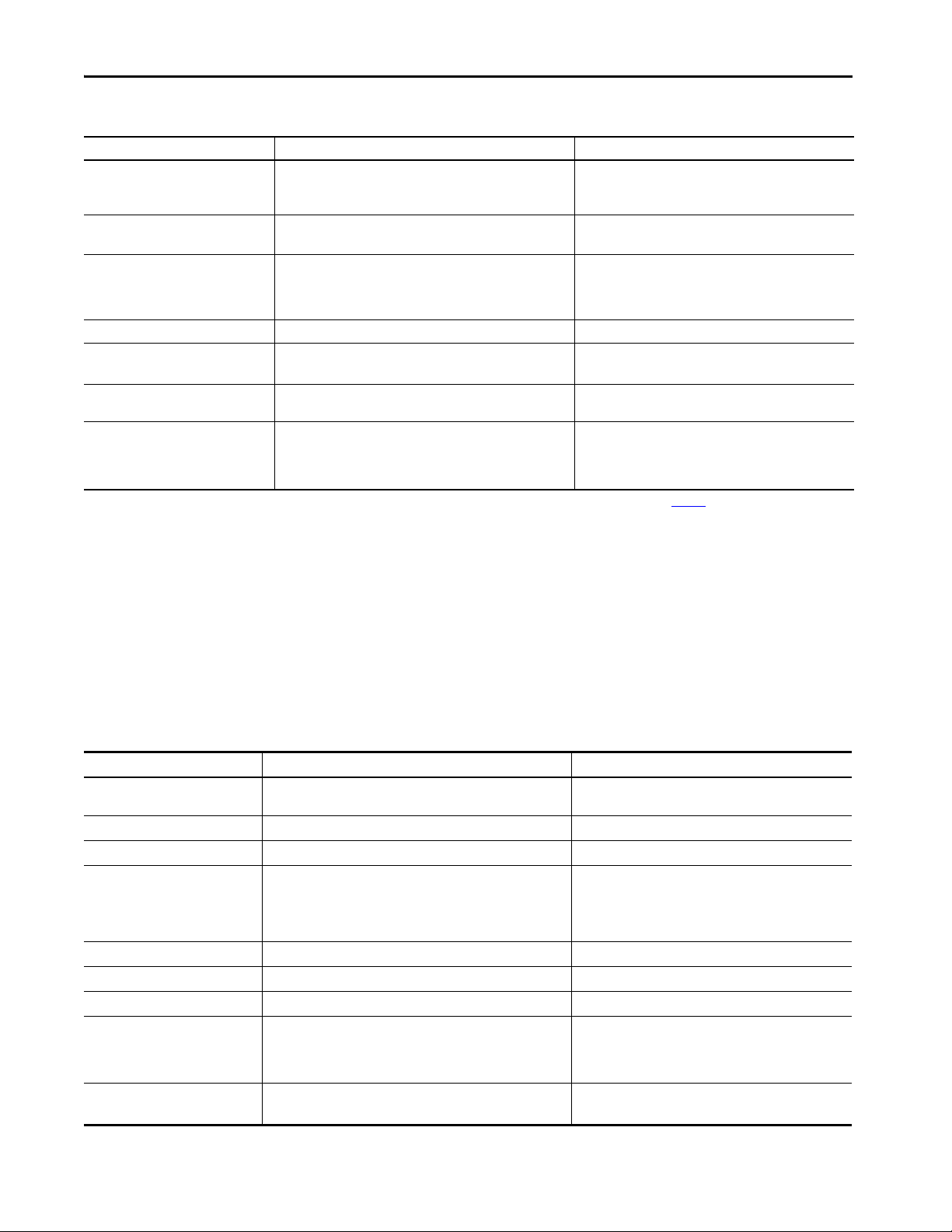
145.20 mm
(5.72 in.)
142.94 mm
(5.63 in.)
34.55 mm
(1.36 in.)
145.20 mm
(5.72 in.)
136.60 mm
(5.50 in.)
34.55 mm
(1.36 in.)
Controller Dimensions
This section shows dimensional differences.
ControlLogix 5570 Dimensions
Logix5572™
RUN FORCE SD OK
ControlLogix 5580 Dimensions
22 Rockwell Automation Publication 1756-RM100F-EN-P - October 2018
Logix5572S™
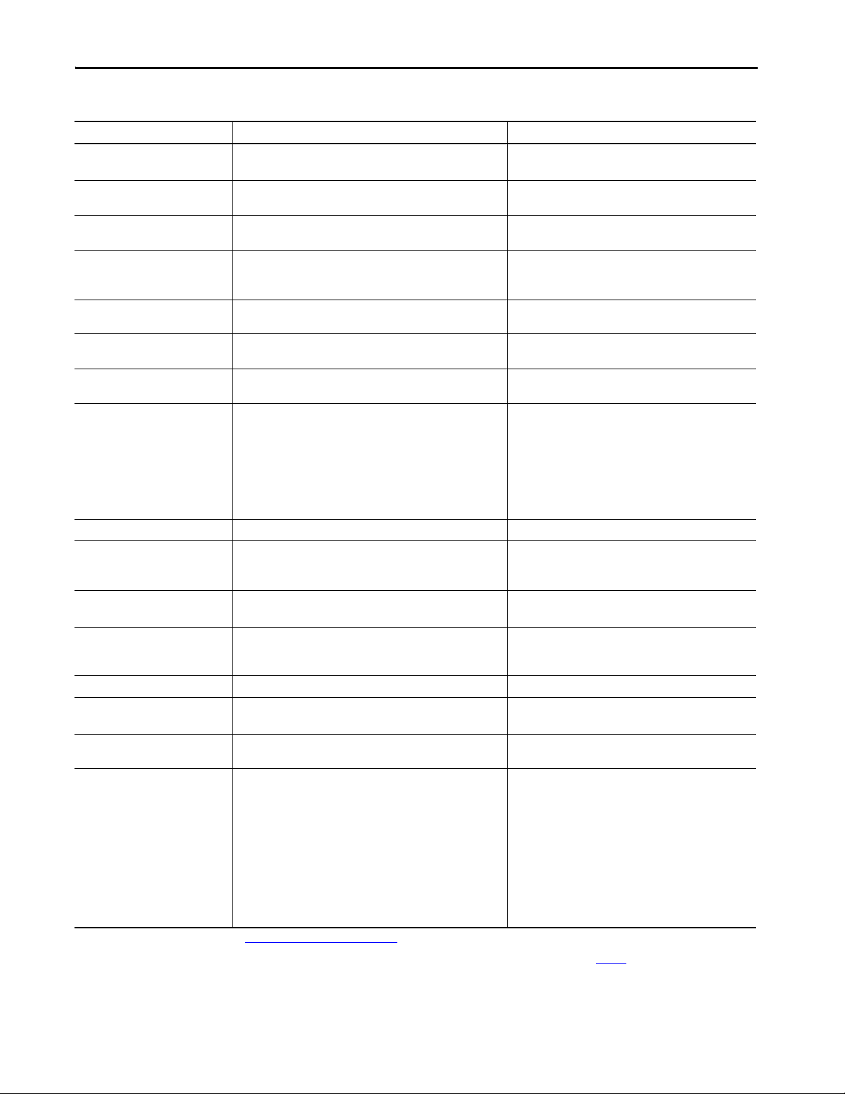
145.20 mm
(5.72 in.)
142.94 mm
(5.63 in.)
34.55 mm
(1.36 in.)
139.6 mm
(5.50 in.)
34.55 mm
(1.360 in.)
145.2 mm
(5.717 in.)
Front view: GuardLogix 5580 Controller, GuardLogix 5580 Safety Partner
Side view: GuardLogix 5580 Controller, GuardLogix 5580 Safety Partner
34.55 mm
(1.360 in.)
145.2 mm
(5.717 in.)
RUN FORCE SD OK
Replacement Considerations with ControlLogix 5580 and GuardLogix 5580 Systems Chapter 2
GuardLogix 5570 Dimensions
Logix5584ES™
RUN
RUN
FORCE SD OK
REM
GuardLogix 5580 Dimensions
Logix55L8SP™
NET
LINK
OK
PROG
32714-M
Rockwell Automation Publication 1756-RM100F-EN-P - October 2018 23
Chapter 2 Replacement Considerations with ControlLogix 5580 and GuardLogix 5580 Systems
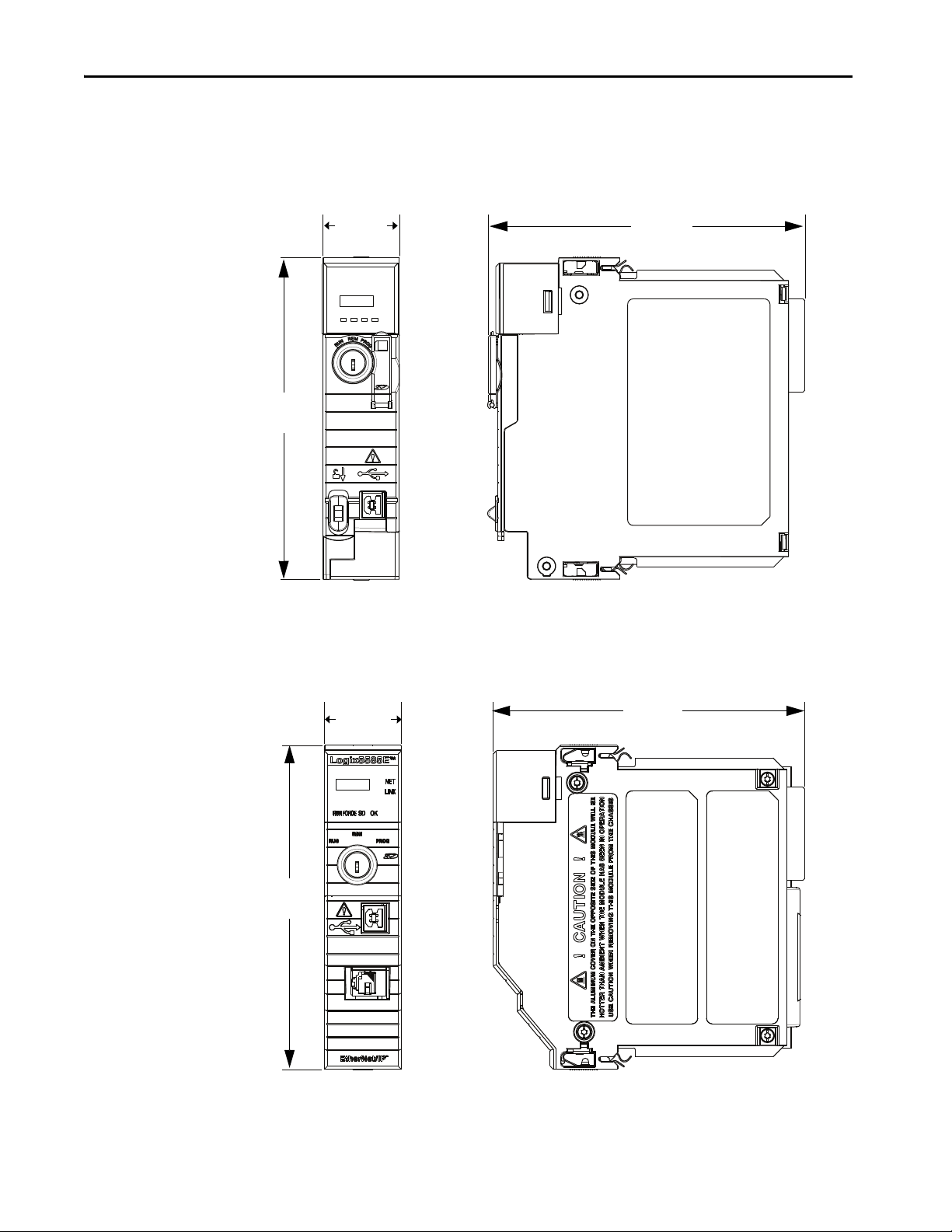
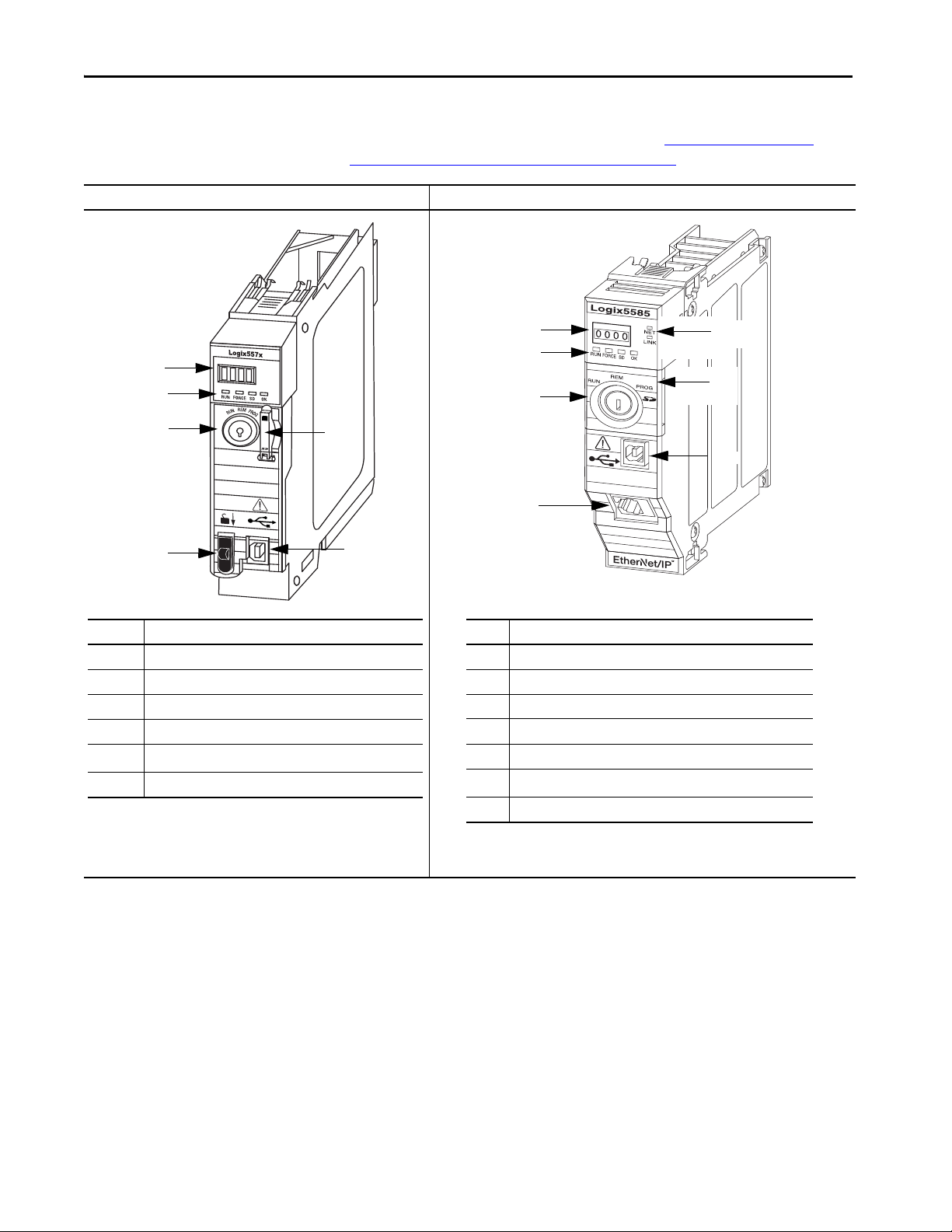
Item Description
14-character Display
2 Status Indicators
3REM RUN PROG Key
4 Energy Storage Module Release
5
SD Card slot behind the door
(1)
(1) The door opens from top to bottom.
6USB Port
1
2
3
5
6
4
1
7
4
3
5
6
2
Item Description
14-character Display
2 Status Indicators
3REM RUN PROG Key
4 Ethernet Port
5 Ethernet Status Indicators
6
SD Card slot and Reset button are behind the door.
(1)
(1) First remove the key, then open the door from right to left.
7USB Port
Connectors and Status Indicators
ControlLogix 5570 ControlLogix 5580
This section shows the front plate differences. For more information on the
status indicators and reset button, see Chapter 7, Diagnostics and Status
Indicators with ControlLogix Systems on page 141.
24 Rockwell Automation Publication 1756-RM100F-EN-P - October 2018
32511-M
Replacement Considerations with ControlLogix 5580 and GuardLogix 5580 Systems Chapter 2
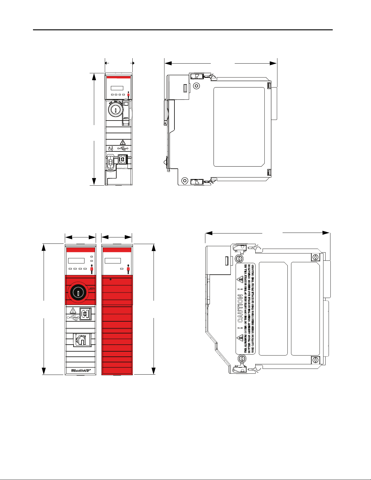
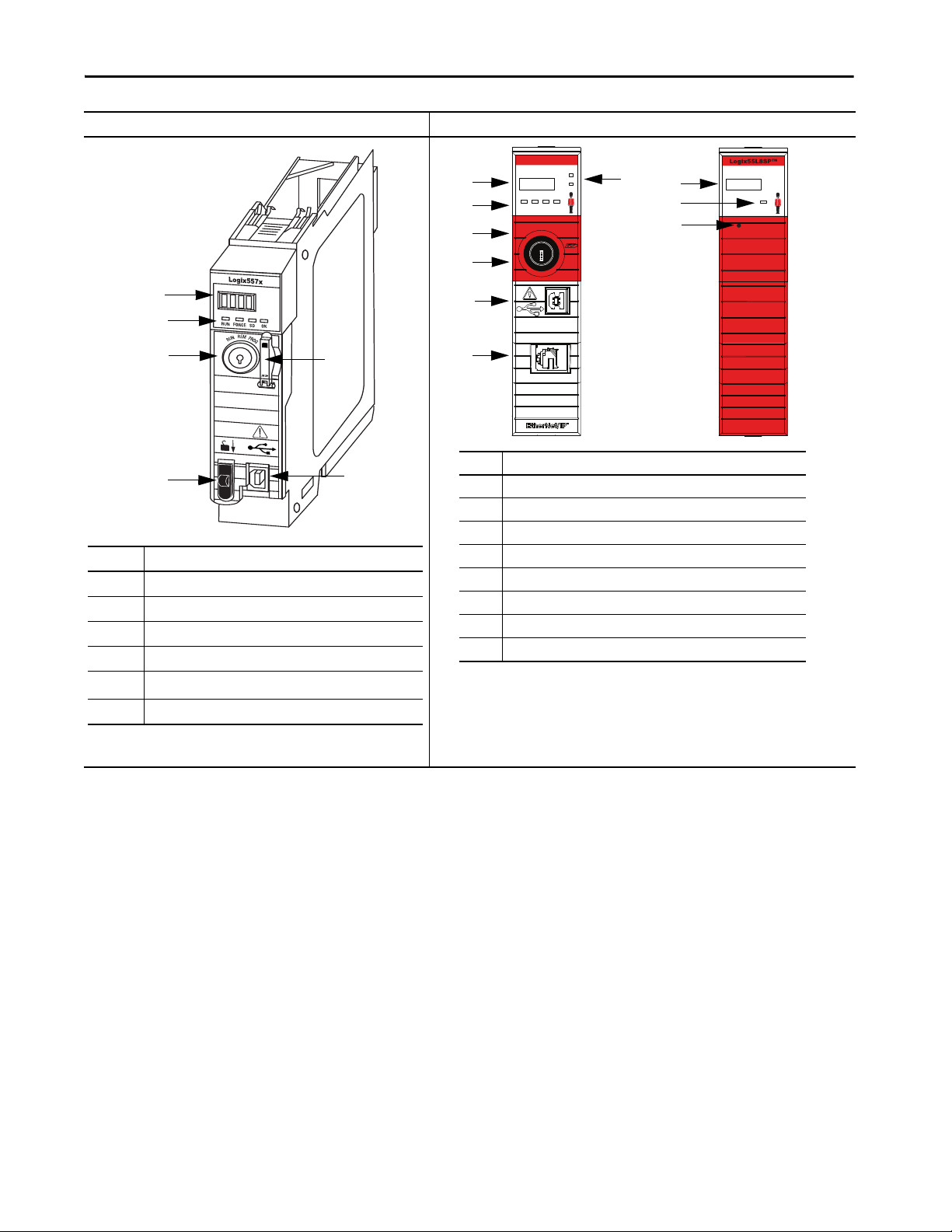
Item Description
14-character Display
2 Status Indicators
3REM RUN PROG Key
4 Energy Storage Module Release
5
SD Card slot behind the door
(1)
(1) The door opens from top to bottom.
6USB Port
1
2
3
5
6
4
1
5
3
7
2
Item
Description
14-character display
2 Status Indicators
3 Mode switch (Remote, Run, Program)
4 SD card slot and Reset Button behind the door
(1)
(1) First remove the key, then open the door from right to left.
5USB Port
6Ethernet Port
7Ethernet Status Indicators
8 Safety Partner Reset Button
6
4
1
2
8
GuardLogix 5570 GuardLogix 5580 and Safety Partner
Logix5584ES™
NET
LINK
RUN
FORCE SD OK
REM
RUN
PROG
OK
Rockwell Automation Publication 1756-RM100F-EN-P - October 2018 25

Chapter 2 Replacement Considerations with ControlLogix 5580 and GuardLogix 5580 Systems
Project Size
Configure the Controller
The size of the .ACD file does not reflect the size of your project that
downloads to the controller. The .ACD file contains multiple components.
Not all components are downloaded to the controller.
You must consider how to best use controller resources when ControlLogix
controllers communicate over an EtherNet/IP network. There are limitations
concerning how much EtherNet/IP communication the controller supports.
Consider the following:
•Connections
•Ethernet Nodes
Connections Overview
A Logix 5000™ controller provides connection resources whenever
communications are established between two devices.
Connections are used when the system contains the following conditions
or activities:
• I/O modules, communication modules, and adapters are present in the
I/O configuration of the user project
• Produced or Consumed tags are configured in the user project
• Connected Messages are executed in the user application
• External devices, programming terminals, or HMIs communicate with
the controller
You must track the number of connections that are used when you configure a
ControlLogix 5570 control system.
26 Rockwell Automation Publication 1756-RM100F-EN-P - October 2018
Replacement Considerations with ControlLogix 5580 and GuardLogix 5580 Systems Chapter 2
Nodes on an EtherNet/IP Network
When used in a Logix Designer application project, version 28 or later,
5580 controllers offer a simplified method for counting controller resources.
When you configure a 5580 control system, you simply count the number of
Ethernet nodes that you include in the I/O configuration section of your Logix
Designer application project.
On the Controller Properties dialog box, the Logix Designer application
project displays the updated number of nodes that are used as you add Ethernet
nodes to the project.
To see an example of how the project displays the node count, see Figure 3 on
page 32. Ta b l e 5 lists the EtherNet/IP node limits for 5580 controllers.
Table 5 - 5580 Controller EtherNet/IP Node Guidelines
Cat. No. Maximum Number of EtherNet/IP Nodes Supported
Logix Designer Application,
Versi on 28
1756-L81E Not applicable 60 100 100
1756-L81ES Not applicable 100
1756-L82E Not applicable 80 175 175
1756-L82ES Not applicable 175
1756-L83E 100 100 250 250
1756-L83ES Not applicable 250
1756-L84E Not applicable 150 250 250
1756-L84ES Not applicable 250
1756-L85E 300 300 300 300
Logix Designer Application,
Versi on 29
Logix Designer Application,
Version 3 0
Logix Designer Application,
Version 31 or later
Devices Included in the Node Count
Any devices that you add directly to the I/O configuration section are counted
toward the node limits of the controller. The following are example devices
that must be counted:
• Remote communication adapters
• Devices with an embedded EtherNet/IP port, such as I/O modules,
drives, and linking devices
• EtherNet/IP devices that are connected to a communication module in
the local chassis
• Remote controllers when a produce/consume connection is established
between the two controllers
• HMI devices that are included in the I/O configuration tree
• Third-party devices that are directly connected to the EtherNet/IP
network
Rockwell Automation Publication 1756-RM100F-EN-P - October 2018 27
Chapter 2 Replacement Considerations with ControlLogix 5580 and GuardLogix 5580 Systems
Devices Excluded from the Node Count
Ethernet devices that exist on the EtherNet/IP network but are not added to
the I/O configuration of the project do not count as nodes. These items are not
added to the I/O configuration and are not considered nodes:
•Computer
• EtherNet/IP communication modules that reside in the local chassis
with the controller
• HMI that is not added to the I/O configuration section
•MSG instruction
• Standard Ethernet devices for which the controller uses a socket
interface to communicate
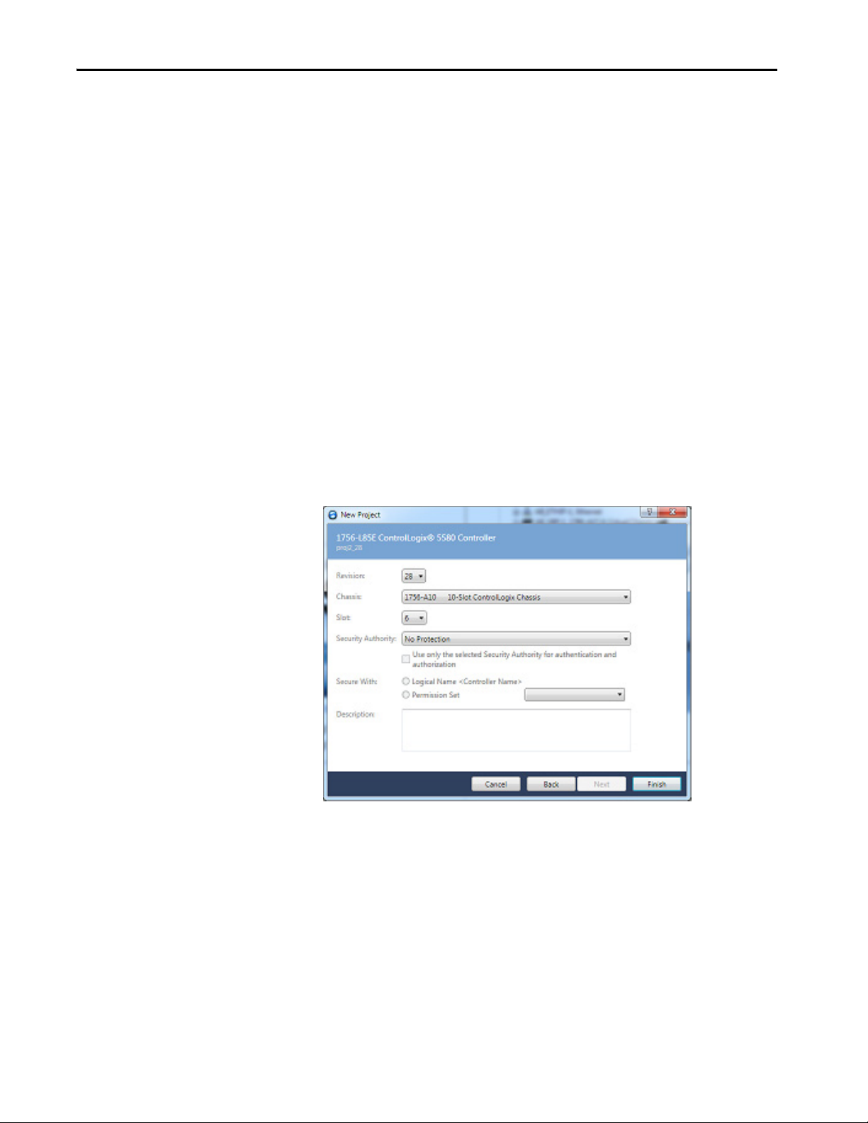
New Project Dialog Box
When you create a project with a 5580 controller, the Module Definition
dialog box appears. The dialog box provides standard controller settings, along
with additional security settings. The information that is entered in this dialog
box displays on the Controller Properties General tab and Security tab.
28 Rockwell Automation Publication 1756-RM100F-EN-P - October 2018
Replacement Considerations with ControlLogix 5580 and GuardLogix 5580 Systems Chapter 2
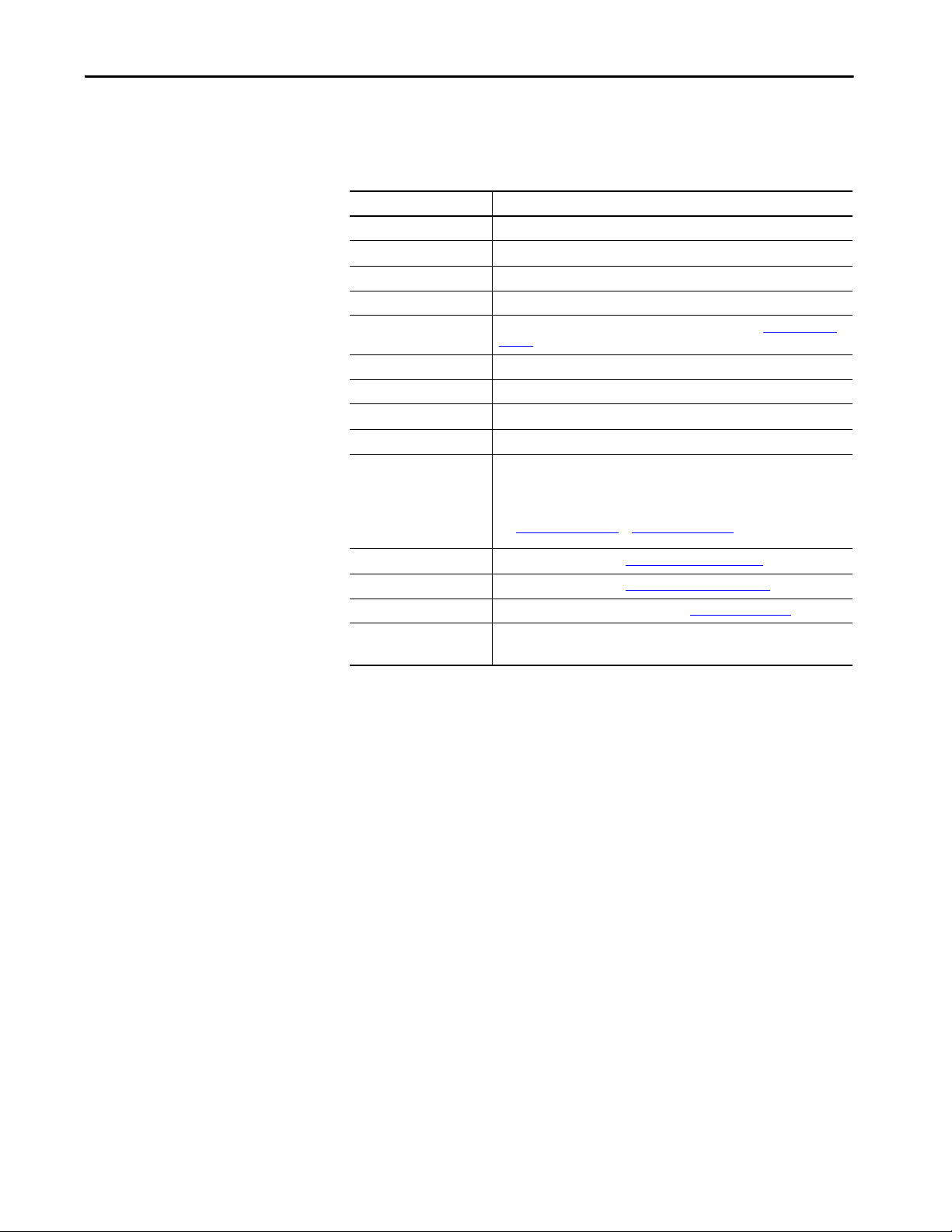
Controller Properties
This table compares the Controller Properties Tab.
Controller Properties Tab Comments
General Same functionality as 5570 controllers.
Major Faults Same functionality as 5570 controllers.
Minor Faults Same functionality as 5570 controllers.
Date/Time Same functionality as 5570 controllers.
Advanced New parameter to enable Minor Overflow fault reporting. See Advanced Tab on
SFC Execution Same functionality as 5570 controllers.
Project Same functionality as 5570 controllers.
Redundancy Currently not available for 5580 controllers.
Nonvolatile Memory Same functionality as the 5570 controllers.
Memory (Logix Designer
application, version 28)
Capacity (Logix Designer
application, version 29 and
later)
Internet Protocol New for 5580 controllers. See Internet Protocol Tab on page 34
Port Configuration New for 5580 controllers. See Port Configuration Tab on page 35.
Security Now has additional security parameters. See Security Tab on page 36
Alarm Log Not available for 5580 controllers in version 28.
page 30
The tabs indicate the same information but are named differently between the
Logix Designer application versions.
Indicates data usage. Data usage is indicated with one value that combines Data
and Logic memory usage and I/O memory usage.
See Memory Tab on page 31
Available in version 29 or later with the same functionality as the 5570 controllers.
or Capacity Tab on page 32.
.
.
Rockwell Automation Publication 1756-RM100F-EN-P - October 2018 29
Chapter 2 Replacement Considerations with ControlLogix 5580 and GuardLogix 5580 Systems
Report Overflow Faults is ena bled by default when
morphing a legacy projec t, but defaults to disabled
when creating a ControlLogix 5580 project.
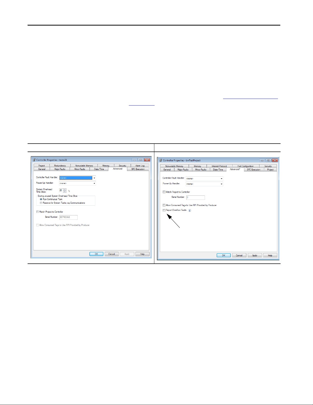
Advanced Tab
The Advanced tab provides a way to assign the Controller Fault Handler and
Power-up Handler. You can also match a project to a specific controller by
serial number.
• Report Overflow Faults is a new parameter that lets you control Minor
Overflow fault reporting. When you create a project, the default setting
is disabled. When you import or open a legacy project, the default
setting is enabled. For more information, see Minor Fault on Overflow
on page 128.
• System Overhead Time Slice is no longer required for 5580 controllers,
and the parameter is removed.
Figure 1 - Controller Properties Dialog Box - Advanced Tab
5570 Controllers Example 5580 Controllers Example
30 Rockwell Automation Publication 1756-RM100F-EN-P - October 2018

Replacement Considerations with ControlLogix 5580 and GuardLogix 5580 Systems Chapter 2
Memory Tab
In the Logix Designer application, version 28 or earlier, the Memory tab
indicates data usage.
• 5570 controllers - Data usage is indicated with two values. The tab
shows I/O memory and Data and Logic memory separately.
As you change the project, you can click Estimate to see the estimated
memory usage and remaining available memory.
• 5580 controllers - Data usage is indicated with one value that combines
Data and Logic memory usage and I/O memory usage.
As you change the project, the data values are automatically updated to
indicate the estimated memory usage and remaining available memory.
Figure 2 - ControlLogix Controller Properties Dialog Box - Memory Tab
ControlLogix 5570 Version 28 Example ControlLogix 5580 Version 28 Example
Rockwell Automation Publication 1756-RM100F-EN-P - October 2018 31
Chapter 2 Replacement Considerations with ControlLogix 5580 and GuardLogix 5580 Systems
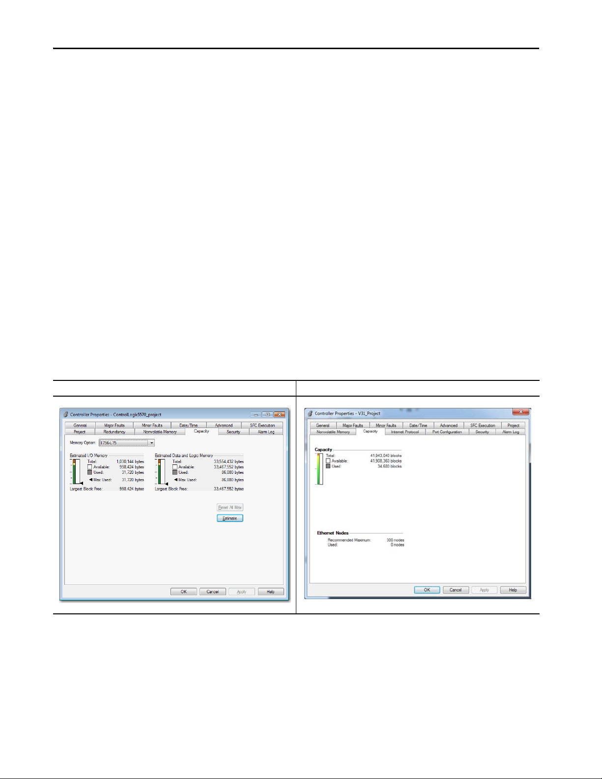
Capacity Tab
In the Logix Designer application, version 29 or later, the Capacity tab
indicates data usage.
• 5570 controllers - Data usage is indicated with two values. The tab
shows I/O memory and Data and Logic memory separately.
GuardLogix 5570 controllers also show the Safety memory.
As you change the project, you can click Estimate to see the estimated
memory usage and remaining available memory.
• 5580 controllers - Data usage is indicated with one value that combines
Data and Logic memory usage and I/O memory usage. The tab also
shows the number of Ethernet nodes that are used. GuardLogix 5580
controllers also show the Safety capacity.
As you change the project, the data values are automatically updated to
indicate the estimated memory usage and remaining available memory.
The number of Ethernet nodes is also updated automatically.
As you change the project, the data values are automatically updated.
Figure 3 - ControlLogix Controller Properties Dialog Box Version 29 or later- Capacity Tab
ControlLogix 5570 Example ControlLogix 5580 Example
32 Rockwell Automation Publication 1756-RM100F-EN-P - October 2018
Replacement Considerations with ControlLogix 5580 and GuardLogix 5580 Systems Chapter 2
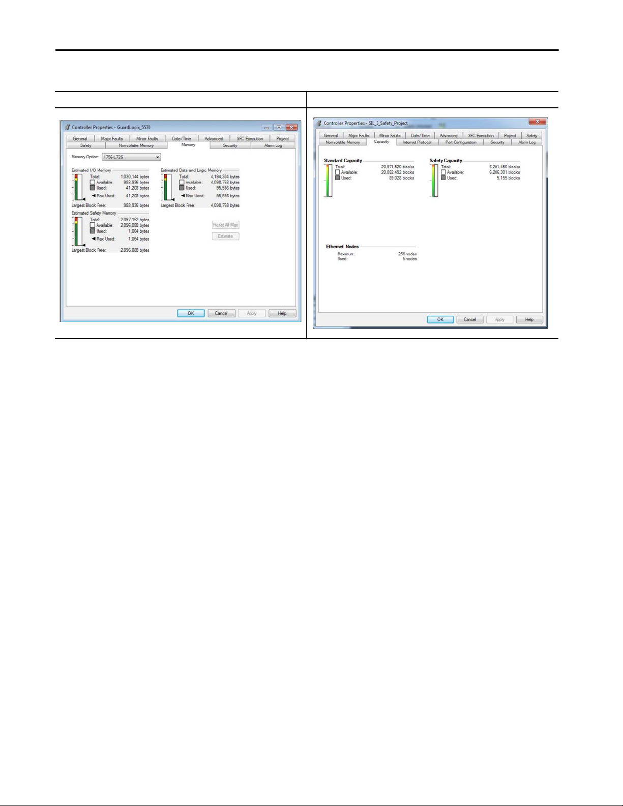
Figure 4 - GuardLogix Controller Properties Dialog Box - Capacity Tab
GuardLogix 5570 Version 28 Example GuardLogix 5580 Version 31 or later Example
Rockwell Automation Publication 1756-RM100F-EN-P - October 2018 33
Chapter 2 Replacement Considerations with ControlLogix 5580 and GuardLogix 5580 Systems
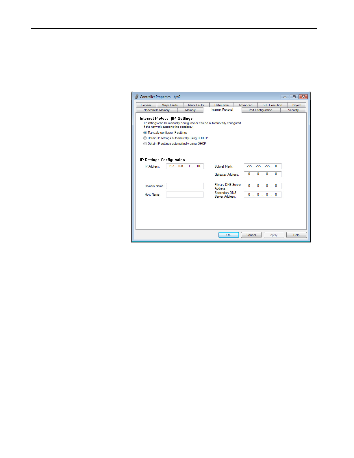
Internet Protocol Tab
When online with the controller, the Internet Protocol tab lets you configure
the IP Settings. These settings are not available offline.
Figure 5 - Controller Properties Dialog Box - Internet Protocol Tab - Online
When online, configurable settings include the following:
• Source of IP Settings (DHCP, BOOTP, or manual configuration)
• Physical Module IP Address
•Subnet Mask
• Gateway Address
•Domain Name
•Host Name, Primary DNS Server Address
•Secondary DNS Server Address
34 Rockwell Automation Publication 1756-RM100F-EN-P - October 2018
Replacement Considerations with ControlLogix 5580 and GuardLogix 5580 Systems Chapter 2
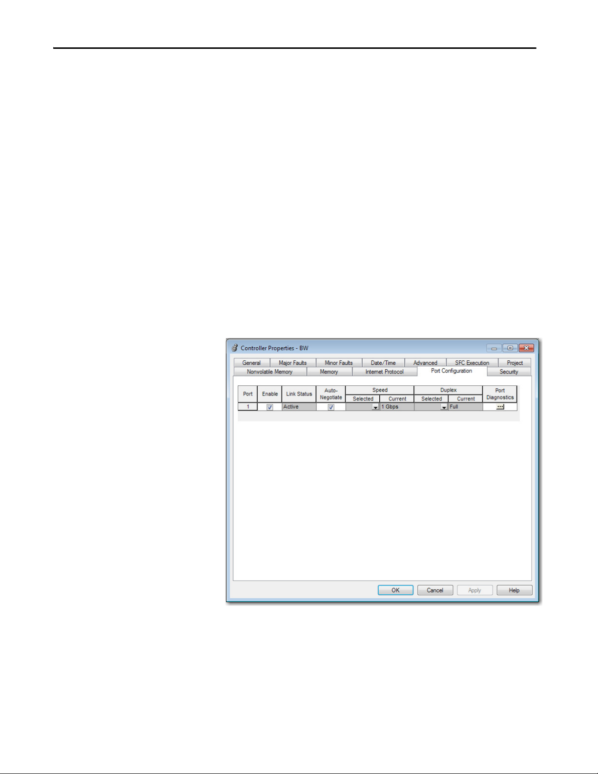
Port Configuration Tab
When online, the Port Configuration tab lets you view and configure the
Ethernet port settings:
•View Link Status
• Enable/Disable the Ethernet port
• Configure Auto-Negotiate
• Configure Selected Speed up to 1 Gbps (or set to auto-negotiate)
•View Current Speed
• Configure Selected Duplex
The 5580 controllers only support full-duplex.
•View Current Duplex
• Access the Port Diagnostics dialog
You can change the Port Configuration parameters without resetting
the controller.
Figure 6 - Controller Properties Dialog Box - Port Configuration Tab
Rockwell Automation Publication 1756-RM100F-EN-P - October 2018 35

Chapter 2 Replacement Considerations with ControlLogix 5580 and GuardLogix 5580 Systems
Port Diagnostics
On the Port Configuration category, click the Port Diagnostics button to view
information for the Ethernet port. For parameter descriptions, see the
ControlLogix 5580 and GuardLogix 5580 Controllers User Manual,
publication 1756-UM543
.
Security Tab
The Security Tab lets you see the controller security settings, for example, the
Security Authority choice. Security settings are configured when you create the
project.
With the Logix Designer application, version 28 or later, the 5580 controllers
support additional parameters in the Security Authority section.
Figure 7 - Controller Properties Dialog Box - Security Tab
5570 Controllers Example 5580 Controllers Example
36 Rockwell Automation Publication 1756-RM100F-EN-P - October 2018

Replacement Considerations with ControlLogix 5580 and GuardLogix 5580 Systems Chapter 2
ControlLogix and GuardLogix 5580
controllers Reset Button
OK
1756-L8SP Safety Partner
Reset Button
Controller Reset
You can clear the program from memory on the 5570 controllers. On 5580
controllers, you can clear the program from memory and reset the controller to
factory default settings.
5570 Controllers
Clearing the program from the on-board NVS memory on the
5570 controllers and the 1756-L7SP Safety Partner, involves removing the
Energy Storage Module.
For information on how to perform this procedure, see Knowledgebase
Answer ID 450803, 1756-L7x: Clearing Memory/Resetting Processor to
Factory Default, accessible at https://rockwellautomation.custhelp.com
'
IMPORTANT When you clear the program on a GuardLogix 5570 Controller, you must also
clear the 1756-L7SP Safety Partner.
5580 Controllers
You can clear the program from memory and reset the 5580 controllers and the
1756-L8SP Safety Partner with the reset button.
For information on how to use the reset button, see the ControlLogix 5580
and GuardLogix 5580 Controllers User Manual, publication 1756-UM543
WARNING: When you press the reset button while power is on, an Electric
Arc can occur. This could cause an explosion in hazardous location
installations. Be sure that power is removed or the area is nonhazardous
.
before proceeding.
IMPORTANT In a SIL 3 application, when you reset the GuardLogix 5580 Controller you
must also reset the 1756-L8SP Safety Partner.
Rockwell Automation Publication 1756-RM100F-EN-P - October 2018 37

Chapter 2 Replacement Considerations with ControlLogix 5580 and GuardLogix 5580 Systems
SD Card Behavior
The controller has changed some behaviors when loading a project from the
SD card into a controller. These changes facilitate a better workflow for easier
commissioning of brand new out of box controllers. All Logix 5000 controllers
ship from the factory with firmware revision 1.x.
With 5580 controllers, the Load Image setting On Uninitialized Memory is
available. This setting replaces the On Corrupt Memory setting that is available
with 5570 controllers.
The general behavior is the same for both settings. The only difference is the
controller behavior when it is in the out-of-box condition, as described in
Ta b l e 6
.
You can install an SD card that uses On Uninitialized Memory in an out-of the
box controller, that is, one that uses firmware revision 1.
x. In this case, at power-
up the image loads both the controller firmware and controller application.
5570 Controllers Example 5580 Controllers Example
When you use an SD card with an image in an out-of-box controller (firmware
revision 1.x), at power-up that controller updates its firmware to the revision
stored on the card. The update happens regardless of the Load Image setting
you made when you transferred the image to the SD card.
The On Power Up, and On Initialized Memory settings also load the
controller application into an out of box controller.
This table shows what happens at power-up when you insert an SD card that
contains an image into a 5580 controller.
Table 6 - SD Card Settings and Controller Power-up Behavior
Image Setting Controller is in Out-of-Box Condition
User Initiated Loads Firmware Only
On Power Up Loads both Firmware and Application • Loads Firmware if there is a revision mismatch
On Uninitialized Memory Loads both Firmware and Application
(1) Indicates change in behavior from ControlLogix 5570 and older controllers.
(2) “Valid” includes the No Project condition.
(v1.x firmware)
(1)
Firmware > 1.x and Internal Nonvolatile
Memory is not Valid
Does Nothing Does Nothing
• Loads Application
(1)
• Loads Firmware if there is a revision mismatch
• Loads Application
(2)
Firmware > 1.x and Internal Nonvolatile
Memory is Valid
• Loads Firmware if there is a revision mismatch
• Loads Application
Does Nothing
(2)
38 Rockwell Automation Publication 1756-RM100F-EN-P - October 2018

Replacement Considerations with ControlLogix 5580 and GuardLogix 5580 Systems Chapter 2
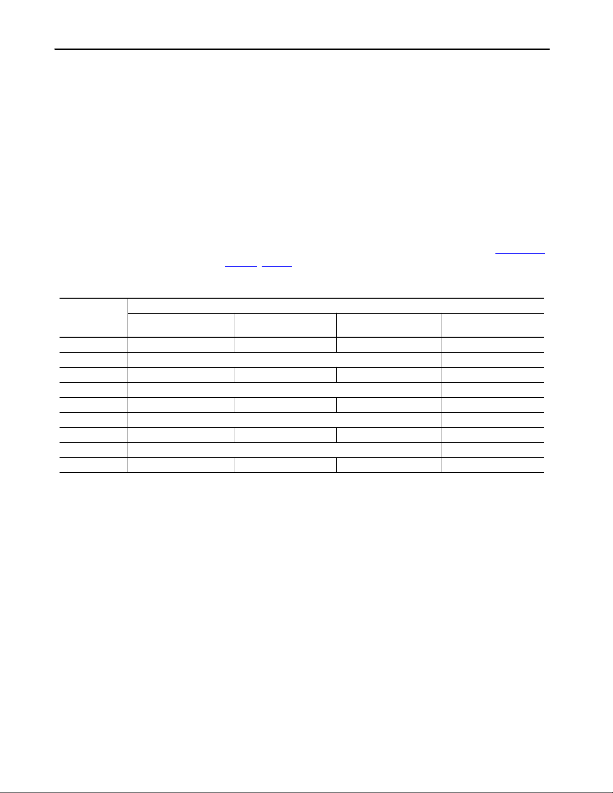
Communication Options
Several communication networks are available for use. This table describes
typical network applications that are used, and lists the networks available to
support such applications.
Application Type 5570 Controllers -
Communication options • EtherNet/IP
Integrated Motion • EtherNet/IP
Time Synchronization EtherNet/IP - Available with Integrated Motion and non-motion
Control of distributed I/O • ControlNet
Produce/consume data between
controllers
Messaging to and from other devices,
including access to the controller via
Logix Designer application
(1) With Studio 5000 Logix Designer Application Version 31.00.00 or later.
Supported Networks
• ControlNet®
• DeviceNet®
• Data Highway Plus™ (DH+™)
• Remote I/O
•SynchLink™
•USB Client
• SERCOS interface
• Analog options:
– Encoder input
–LDT input
– SSI input
applications
• DeviceNet
• EtherNet/IP
• Foundation Fieldbus
•HART
• Universal remote I/O
•ControlNet
• EtherNet/IP
•ControlNet
• DeviceNet (only to devices)
• Data Highway Plus (DH+)
•DH-485
• EtherNet/IP
5580 Controllers Supported Networks
EtherNet/IP
• SERCOS interface
• Analog options:
– Encoder input
–LDT input
– SSI input
(1)
(1)
Rockwell Automation Publication 1756-RM100F-EN-P - October 2018 39
Chapter 2 Replacement Considerations with ControlLogix 5580 and GuardLogix 5580 Systems
Communication Throughput
Unlike 5570 controllers, which shares the main core between application code
and communications, 5580 controllers run communications asynchronously
from the user application.
This implementation provides better communications throughput in both the
bandwidth and speed of data the 5580 controllers can deliver to and from, for
example, HMIs, Historians, and MES systems. It also improves the overall
application performance as the controller no longer has to task switch and
pause application execution to handle HMI or other class 3 traffic.
For 5570 and 5580 controllers, the controller runs communication
asynchronously to the application, make sure communication that is delivered
to the controller is complete before the application executes on the newly
delivered data. This applies to both data that comes into the controller and
data that goes out.
For example, if the HMI is writing a large block of recipe data to the controller,
application code can start executing on that recipe data before the data writing
process finishes. This action results in half of the current recipe and half of the
last recipe in the application space.
Traditionally, programmers have used the following techniques to control the
effects of asynchronous communications:
•UID/UIE pairs
•Periodic tasks
•Moving data with CPS instructions
The techniques all rely on controlling when the main core can switch tasks.
This helps to prevent the communications task from changing data while the
control task used it. Because the controller processes communications on an
independent core of the CPU, then UID/UIE pairs and Periodic Tasks are not
as effective in all cases.
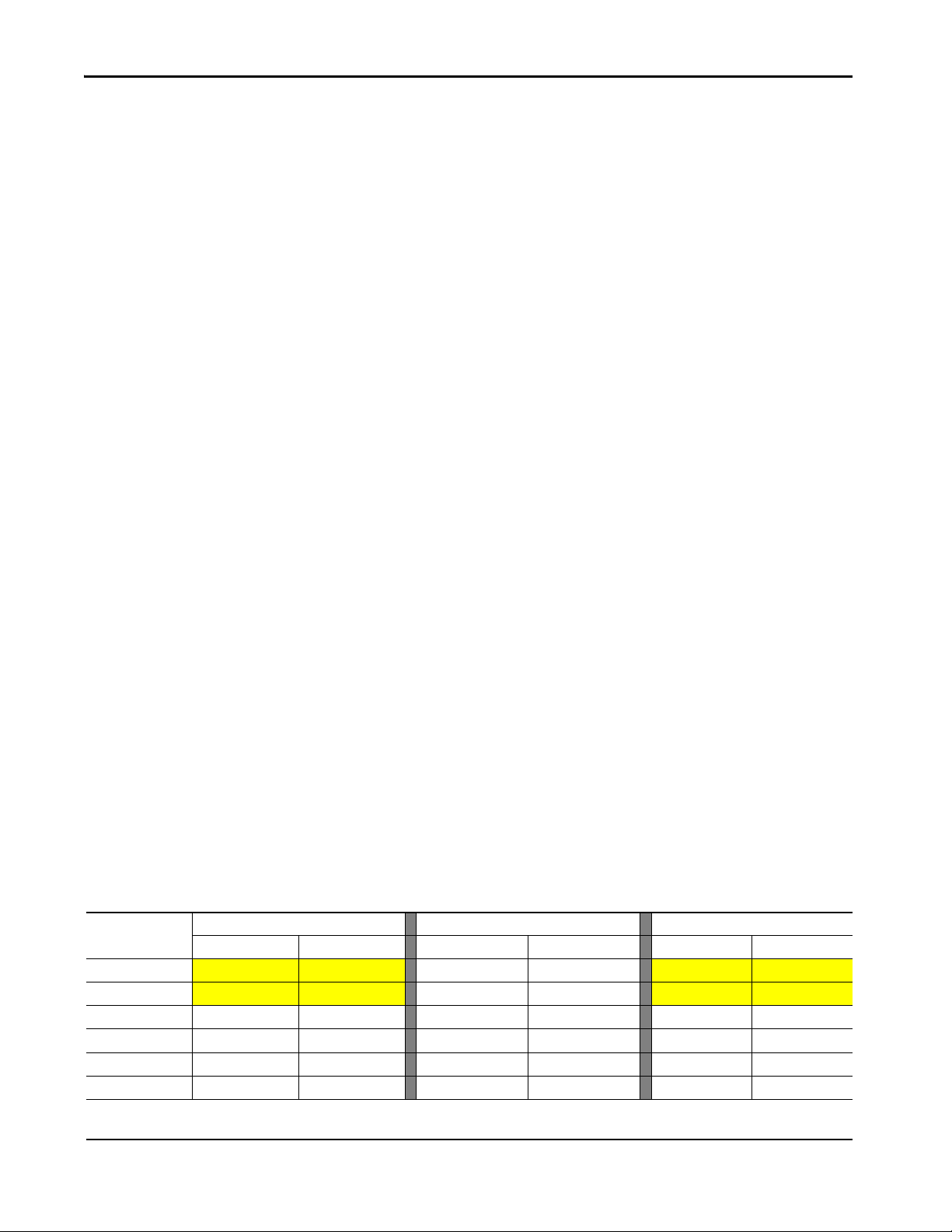
The items that are highlighted in this table are where controller behavior
differs.
Table 7 - ControlLogix 5570 and ControlLogix 5580 Controller Behavior Differences
Tag Read/Write
Source
HMI
MSG
I/O Update Allows Allows
Produce/Consume Allows Allows
Other User Tasks Blocks Blocks
Motion Planner Allows Allows
Blocks - Stops source data values from change by communications during application execution.
Allows - Communications can change source data values during application execution.
5580 Controllers 5570 Controllers
Allows Blocks Blocks Blocks Allows Blocks
Allows Blocks Blocks Blocks Allows Blocks
UID/UIE CPS Peri odic Task
5580 Controllers 5570 Controllers 5580 Controllers 5570 Controllers
Blocks Blocks Allows Allows
Blocks Blocks Allows Allows
Blocks Blocks Allows Allows
Blocks Blocks Allows Allows
40 Rockwell Automation Publication 1756-RM100F-EN-P - October 2018
Replacement Considerations with ControlLogix 5580 and GuardLogix 5580 Systems Chapter 2
Build Button
Because the controllers have 32-bit data integrity, this only applies to data
structures larger than 32 bits. If word-level integrity is your primary concern,
the 32-bit data integrity does not impact your data use.
Good programming practice dictates the use of two unique words at the
beginning and the end of data. The controller validates the words to assure the
entire structure has data integrity. We recommend that the handshake data is
changed and the application code validates it every transaction before the
controller application code or higher-level system reading controller data acts
on it.
Download the Program to the Controller
The first time that you download a program, it can take longer than subsequent
downloads. These situations can affect download/compile times:
• The capability of the personal computer or laptop.
• You download the project immediately after a project import or upload,
but before Logix Designer has compiled the project once.
• You edit a User Defined Tag (UDT), Add-On Instruction (AOI), or an
object that is used in many places.
• Increased load when Logix Designer compiles and generates code.
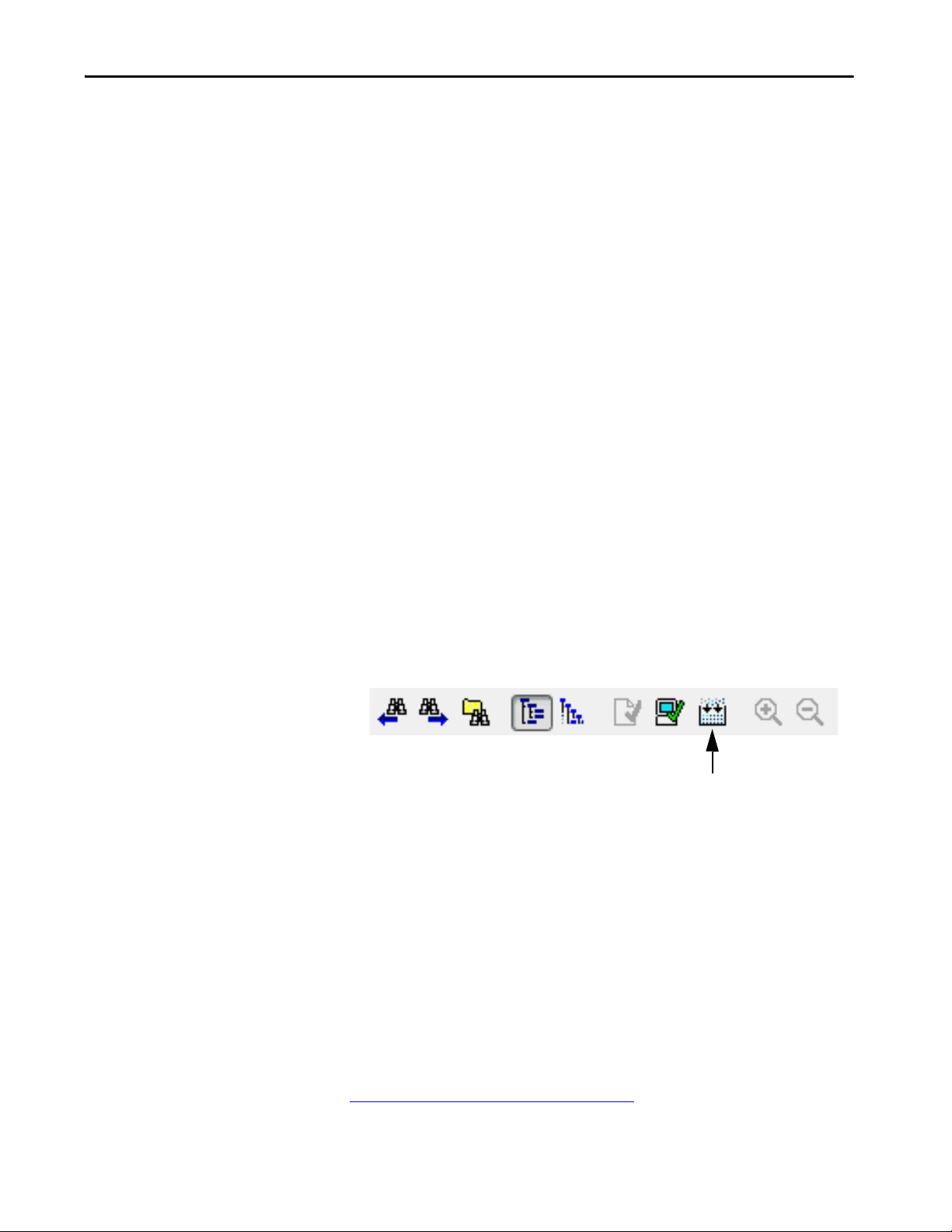
Build Button
The new Build button in Logix Designer creates binary files that are compiled
from user subroutines, and caches them in the project .ACD file.
If these files are present in the project during a download, then Logix Designer
does not have to recompile them, and saves time during the download process.
Every download requires that only the changed subroutines must be
recompiled. You can perform a build offline, save the project .ACD file, and
later distribute it to many controllers without recompilation.
This manual build step is optional. If you do not use the build button, Logix
Designer builds all necessary files when you initiate a download.
An imported project requires a complete rebuild, and extends the download
process the first time you attempt a download.
Downloading Workflow Change on page 42
download changes.
Rockwell Automation Publication 1756-RM100F-EN-P - October 2018 41
provides an explanation of the

Chapter 2 Replacement Considerations with ControlLogix 5580 and GuardLogix 5580 Systems
Downloading Workflow Change
Offline builds can save time when doing subsequent downloads.
5580 Controllers 5570 Controllers
Only changed source code is recompiled on a download. All source code is recompiled on every project download.
Mitigation
Adjust your workflow to save workstations from having to rebuild the project.
You can do offline builds, save the project file, and distribute it to other
workstations to minimize your download times.
Upload Fidelity Change
When you upload, projects that contain program parameters and aliases now
are faithfully reproduced. The uploaded Ladder Diagram source code is an
exact replica of what was downloaded. This was not the case in 5570 controller
Ladder Diagram subroutines, which referenced aliases or program parameters.
42 Rockwell Automation Publication 1756-RM100F-EN-P - October 2018

Replacement Considerations with ControlLogix 5580 and GuardLogix 5580 Systems Chapter 2
Threshold for controller to declare a `Hardware Preservation
Fault’, and reset the module and disable power.
In the disabled power condition, only the OK status indicator is
illuminated, and it is red. The module does not apply power
until it has cooled below the Hardware Preservation Hysteresis
limit. The module then enters fault mode, records the fault in
the major fault log, and displays `CPU Temperature Fault’ on
the front panel.
Threshold for controller to declare a `CPU Temperature Fault’
major recoverable fault. If a fault handler does not clear the
fault, then the module enters fault mode, records the fault in
the major fault log, and displays `T17:C34 CPU Temperature
Fault’ on the front panel.
Threshold for controller to declare a `T17:C35 Controller internal
temperature is approaching operating limit’ minor fault and set
the Diagnostics minor fault bit.
The fault is recorded in the minor fault log, but is not displayed
on the front panel. If the temperature returns to an acceptable
range, the Diagnostics minor fault bit clears, but the minor fault
record remains.
Power to the
controller is
disabled
Hardware Preservat ion
Hysteresis Limit
Power does not
become enabled
when in this range
All power to the controller is disabled except
to run the red OK status indicator and
monitor the temperature.
Thermal Monitoring and Thermal Fault Behavior
The controllers can monitor internal module temperatures and respond as the
temperature increases.
Figure 8 - Controller Thermal Fault Behavior
Rockwell Automation Publication 1756-RM100F-EN-P - October 2018 43

Chapter 2 Replacement Considerations with ControlLogix 5580 and GuardLogix 5580 Systems
Notes:
44 Rockwell Automation Publication 1756-RM100F-EN-P - October 2018

Chapter 3
Replacement Considerations with
CompactLogix and Compact GuardLogix
Systems
Topic Page
Minimum Requirements 46
Product Comparison 47
Controller Spacing 51
Controller Dimensions 53
Connectors and Status Indicators 55
Power the Controller 57
Project Size 58
Configure the Controller 58
Controller Reset Button 67
SD Card Behavior 68
Communication Options 69
EtherNet/IP Modes 72
Use I/O Modules in CompactLogix Systems 74
Download the Program to the Controller 79
Thermal Monitoring and Thermal Fault Behavior 81
This chapter describes features and functions that are associated these
controllers:
• CompactLogix™ 5380 controllers when used with the Studio 5000
Logix Designer® application, version 28 or later.
• Compact GuardLogix® 5380 controllers when used with the Studio
5000 Logix Designer application, version 31 or later.
This chapter features these controllers, and where applicable, the controllers
are known as:
Controller Family Includes These Controllers
5380 controllers CompactLogix 5380 and Compact GuardLogix 5380 controllers
5370 controllers CompactLogix 5370 and Compact GuardLogix 5370 controllers
Rockwell Automation Publication 1756-RM100F-EN-P - October 2018 45

Chapter 3 Replacement Considerations with CompactLogix and Compact GuardLogix Systems
The features and functions described in this chapter are not an exhaustive list
of the features and functions available with the controller. Instead, they provide
a picture of what is new or changed in the controller at this release, including
the following:
• Dual embedded 10/100/1000 Mbps Ethernet ports
•Dual-IP mode
• Higher performance and capacity including :
– Total Motion processing: Support for up to 32 axes (limit differs by
controller catalog number)
– Total I/O packets processing: 128,000 pps
– 320 unconnected message buffers
– 256 simultaneous cached message instructions in the running state
– Support for up to 180 Ethernet nodes (limit differs by controller
catalog number)
• Support for Compact 5000™ I/O modules as local and remote I/O
modules
• Change Ethernet port speed without a module reset
Minimum Requirements
The controllers have these minimum requirements.
CompactLogix Controllers Minimum Requirements
Requirement, Minimum CompactLogix 5370 L3 Controller CompactLogix 5380 Controller
Programming Software Studio 5000 Automation Engineering & Design Environment®,
Version 20.00.00 or later
(1) Most CompactLogix 5380 controllers are first available in version 29.00.00. Also, you must use version 29 or later to use Dual-IP mode with CompactLogix 5380 controllers.
Studio 5000 Logix Designer Application, Version 28.00.00 or
(1)
later
Compact GuardLogix Controllers Minimum Requirements
Requirement, Minimum Compact GuardLogix 5370 Controller Compact GuardLogix 5380 Controller
Programming Software Studio 5000 Automation Engineering & Design Environment,
Version 28.00.00 or later
Studio 5000 Logix Designer Application, Version 31.00.00 or
later
46 Rockwell Automation Publication 1756-RM100F-EN-P - October 2018

Replacement Considerations with CompactLogix and Compact GuardLogix Systems Chapter 3
Product Comparison
The 5380 controllers operate similar to the 5370 controllers, with these
differences.
CompactLogix Controllers Product Comparison
Table 8 - Technical Specifications
Attribute CompactLogix 5370 L3 Controller CompactLogix 5380 Controller
Memory 1769-L30ER, 1769-L30ER-NSE, 1769-L30ERM: 1 MB
1769-L33ER, 1769-L33ERM: 2 MB
1769-L36ERM: 3 MB
1769-L37ERM: 4 MB
1769-L38ERM: 5 MB
Local I/O modules supported 1769 Compact I/O™ only
Number of local I/O modules that are supported varies by controller
catalog number
Embedded Ethernet 10/100 Mbps 10/100/1000 Mbps
Ethernet nodes 1769-L30ER, 1769-L30ER-NSE, 1769-L30ERM: 16
1769-L33ER, 1769-L33ERM: 32
1769-L36ERM: 48
1769-L37ERM: 64
1769-L38ERM: 80
Ethernet performance Ethernet I/O (Class 0/1): 10,000 packets per second max
Ethernet Messaging (Class 3): 400 packets per second max
Dual-IP mode Not supported Supported with the Logix Designer application, version 29
Unconnected message buffers No fixed limits, as long as the controller can allocate the buffer at
Concurrent cached message instructions
in the running state
HMI and Messaging (Class 3) Drawn from the 250 total connections supported by the controller. 512 dedicated messages (256 incoming messages and 256
Integrated motion EtherNet/IP network
Motion axes 1769-L30ERM - As many as 4 axes
Axes/ms over EtherNet/IP™ port As many as 2 (2 ms coarse update period and 50% controller load)
will.
32, drawn from the 250 total connections supported by the
controller.
1769-L33ERM- As many as 8 axes
1769-L36ERM, 1769-L37ERM, 1769-L38ERM - As many as 16 axes
Any combination of these supported axis types:
• CIP™
• Consumed
• Virtual
• Position loop drives
IMPORTANT: Not all CompactLogix 5370 controllers support
Integrated Motion over an EtherNet/IP network.
5069-L306ER, 5069-L306ERM: 0.6 MB
5069-L310ER, 5069-L310ER-NSE, 5069-L310ERM: 1 MB
5069-L320ER, 5069-L320ERM: 2 MB
5069-L330ER, 5069-L330ERM: 3 MB
5069-L340ER, 5069-L340ERM: 4 MB
5069-L350ERM: 5 MB
5069-L380ERM: 8 MB
5069-L3100ERM: 10 MB
Compact 5000 I/O Standard modules only
Number of local I/O modules that are supported varies by
controller catalog number
5069-L306ER, 5069-L306ERM: 16
5069-L310ER, 5069-L310ER-NSE, 5069-L310ERM: 24
5069-L320ER, 5069-L320ERM: 40
5069-L330ER, 5069-L330ERM: 60
5069-L340ER, 5069-L340ERM: 90
5069-L350ERM: 120
5069-L380ERM: 150
5069-L3100ERM: 180
Ethernet I/O (Class 0/1): 128,000 packets per second
Ethernet Messaging (Class 3): 2000 messages per second
or later
320 - Any combination of outbound and inbound messages
256 dedicated buffers
outgoing messages)
5069-L306ERM: As many as 2 axes
5069-L310ERM: As many as 4 axes
5069-L320ERM: As many as 8 axes
5069-L330ERM: As many as 16 axes
5069-L340ERM: As many as 20 axes
5069-L350ERM: As many as 24 axes
5069-L380ERM: As many as 28 axes
5069-L3100ERM: As many as 32 axes
Any combination of these supported axis types:
•CIP
• Consumed
•Virtual
• Position loop drives
As many as 32 when you use the built-in EtherNet/IP port at
1Gbps
IMPORTANT: Not all CompactLogix 5380 controllers support
Integrated Motion over an EtherNet/IP network.
(2)
Rockwell Automation Publication 1756-RM100F-EN-P - October 2018 47
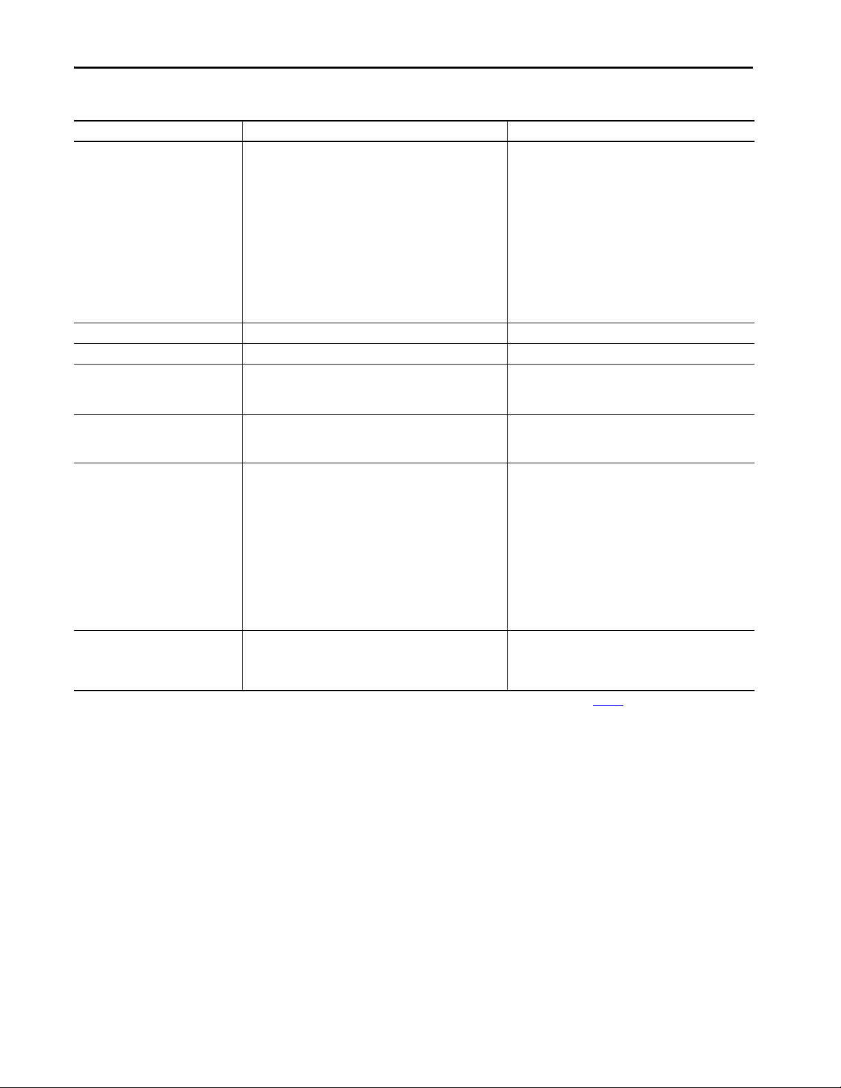
Chapter 3 Replacement Considerations with CompactLogix and Compact GuardLogix Systems
Table 8 - Technical Specifications
Attribute CompactLogix 5370 L3 Controller CompactLogix 5380 Controller
Voltage and current ratings Controller power: 500 mA @ 5.1V DC and 225 mA @ 24V DC MOD Power: 450 mA @ 18…32V DC
MOD Power Inrush: 850 mA for 125 ms
SA Power: 10 mA @ 0…32V DC
25 mA @ 0…240V AC,
47…63 Hz
ATEX/IECEX, 125V AC Max
(3)
MOD Power (Passthrough)
SA Power (Passthrough)
Energy storage module Non-removable Non-removable
Weight, approx 0.31 kg (0.68 lb) 0.394 kg (.868 lb)
Wire ca tegory
(1)
3 - on USB port
2 - on Ethernet port
3 - on USB port
1 - on power ports
2 - on Ethernet port
Wire si ze RJ45 connector according to IEC 60603-7, 2 or 4 pair Category 5e
minimum cable according to TIA 568-B.1 or Category 5 cable
according to ISO/IEC 24702
Ethernet connections:
Ethernet Cabling and Installation according to IEC 61918 and
IEC 61784-5-2
Removable terminal block Not Applicable Kit 5069-RTB64-SCREW or kit 5069-RTB64-SPRING
You must order the kit separately. RTBs do not ship with the
controller.
5069-RTB4-SCREW, 5069-RTB6-SCREW connections:
0.5...1.5 mm
2
(22…16 AWG) solid or stranded copper wire
rated at 105 °C (221 °F), or greater, 3.5 mm (0.14 in.) max
diameter including insulation, single wire connection only
: 9.55 A @ 18…32V DC
(4)
: 9.95 A @ 0…32V DC
9.975 A @ 0...240V AC,
47...63 Hz
ATEX/IECEX, 125V AC Max
5069-RTB4-SPRING, 5069-RTB6-SPRING connections:
0.5...1.5 mm2 (22…16 AWG) solid or stranded copper wire
rated at 105 °C (221 °F), or greater, 2.9 mm (0.11 in.) max
diameter including insulation, single wire connection only
Reset Button Clears the user application and memory but retains the firmware
revision and all network settings
A stage 1 reset clears the user application program and
memory, but retains the controller IP address.
A stage 2 reset returns the controller to out-of box settings
(including firmware), and clears all network settings.
(1) Use this conductor category information for planning conductor routing. See the Industrial Automation Wiring and Grounding Guidelines, publication 1770-4.1.
(2) Data size = 32-bits / 1-DINT
(3) Maximum level of MOD Power current that the module can pass through to the next module in the system. The specific level of current passed through varies based on system configuration.
(4) Maximum level of SA Power current that the module can pass through to the next module in the system. The specific level of current passed through varies based on system configuration.
48 Rockwell Automation Publication 1756-RM100F-EN-P - October 2018

Replacement Considerations with CompactLogix and Compact GuardLogix Systems Chapter 3
Compact GuardLogix Controllers Product Comparison
Table 9 - Technical Specifications
Attribute Compact GuardLogix 5370 Controller Compact GuardLogix 5380 Controller
Memory 1769-L30ERMS: 1 MB standard, 0.5 MB safety
1769-L33ERMS: 2 MB standard, 1 MB safety
1769-L36ERMS: 3 MB standard, 1.5 MB safety
1769-L37ERMS: 4 MB + 1.5 MB safety
1769-L38ERMS: 5 MB + 1.5 MB safety
Local I/O modules supported • 1769 Compact I/O only
Safety I/O support • 1734 POINT Guard I/O™, 1732 ArmorBlock® Guard I/O™,
Embedded Ethernet 10/100 Mbps 10/100/1000 Mbps
Ethernet nodes 1769-L30ERMS: 16
Ethernet performance Ethernet I/O (Class 0/1): 10,000 packets per second max
Dual-IP mode Not supported Supported with the Logix Designer application, version 31
Unconnected message buffers No fixed limits, as long as the controller can allocate the buffer at
Concurrent cached message
instructions in the running state
HMI and Messaging (Class 3) Drawn from the 250 total connections supported by the controller. 512 dedicated messages (256 incoming messages and 256
Integrated motion EtherNet/IP network
• Number of local I/O modules that are supported varies by
controller catalog number
1791 CompactBlock™ Guard I/O™
• Can only communicate to safety I/O through the embedded
Ethernet por ts.
1769-L33ERMS: 32
1769-L36ERMS: 48
1769-L37ERMS: 64
1769-L38ERMS: 80
Ethernet Messaging (Class 3): 400 packets per second max
will.
32, drawn from the 250 total connections supported by the
controller.
5069-L306ERS2, 5069-L306ERMS2: 0.6 MB + 0.3 MB Safety
5069-L310ERS2, 5069-L310ERMS2: 1 MB + 0.5 MB Safety
5069-L320ERS2, 5069-L320ERM: 2 MB + 1 MB Safety
5069-L330ERS2, 5069-L330ERM: 3 MB + 1.5 MB Safety
5069-L340ERS2, 5069-L340ERMS2: 4 MB + 2 MB Safety
5069-L350ERS2, 5069-L350ERMS2: 5 MB + 2.5 MB Safety
5069-L380ERS2, 5069-L380ERMS2: 8 MB + 4 MB Safety
5069-L3100ERS2, 5069-L3100ERMS2: 10 MB + 5 MB Safety
• Compact 5000 I/O Standard and Safety modules only
• Number of local I/O modules that are supported varies by
controller catalog number
• Compact 5000 I/O Safety modules, 1734 POINT Guard I/O,
1732 ArmorBlock Guard I/O,
1791 CompactBlock Guard I/O
• Can communicate to local safety I/O through the backplane,
and also communicate to distributed safety I/O through the
embedded Ethernet ports.
• Can communicate to DeviceNet® safety I/O nodes with the
1788-EN2DN Ethernet to DeviceNet linking device.
5069-L306ERS2, 5069-L306ERMS2: 16
5069-L310ERS2, 5069-L310ERMS2: 24
5069-L320ERS2, 5069-L320ERMS2: 40
5069-L330ERS2, 5069-L330ERMS2: 60
5069-L340ERS2, 5069-L340ERMS2: 90
5069-L350ERS2, 5069-L350ERMS2: 120
5069-L380ERS2, 5069-L380ERMS2: 150
5069-L3100ERS2, 5069-L3100ERMS2: 180
Ethernet I/O (Class 0/1): 128,000 packets per second
Ethernet Messaging (Class 3): 2000 messages per second
or later
320 - Any combination of outbound and inbound messages
256 dedicated buffers
outgoing messages)
(2)
Rockwell Automation Publication 1756-RM100F-EN-P - October 2018 49
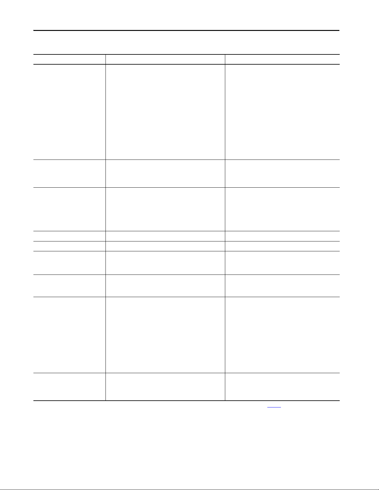
Chapter 3 Replacement Considerations with CompactLogix and Compact GuardLogix Systems
Table 9 - Technical Specifications
Attribute Compact GuardLogix 5370 Controller Compact GuardLogix 5380 Controller
Motion axes 1769-L30ERMS - As many as 4 axes
1769-L33ERMS - As many as 8 axes
1769-L36ERMS, 1769-L37ERMS,1769-L38ERMS - As many as 16
axes
Any combination of these supported axis types:
•CIP
• Consumed
• Virtual
• Position loop drives
Axes/ms over EtherNet/IP port As many as 2 (2 ms coarse update period and 50% controller load) As many as 32 when you use the built-in EtherNet/IP por t at
Voltage and current ratings Controller power: 850 mA @ 5.1V DC and 700 mA @ 24V DC MOD Power: 475 mA @ 18…32V DC
5069-L306ERMS2: As many as 2 axes
5069-L310ERMS2: As many as 4 axes
5069-L320ERMS2: As many as 8 axes
5069-L330ERMS2: As many as 16 axes
5069-L340ERMS2: As many as 20 axes
5069-L350ERMS2: As many as 24 axes
5069-L380ERMS2: As many as 28 axes
5069-L3100ERMS2: As many as 32 axes
Any combination of these supported axis types:
•CIP
• Consumed
• Virtual
• Position loop drives
1 Gbps
IMPORTANT: Not all Compact GuardLogix 5380 controllers
support Integrated Motion over an EtherNet/IP network.
MOD Power Inrush: 1200 mA for 125 ms
SA Power: 10 mA @ 0…32V DC
MOD Power (Passthrough)
SA Power (Passthrough)
(3)
: 4.525 A @ 18…32V DC
(4)
: 9.99 A @ 0…32V DC
Energy storage module Non-removable Non-removable
Weight, approx 0.54 kg (1.18 lb) 0.768 kg (1.693 lb)
Wire ca tegory
(1)
3 - on USB port
2 - on Ethernet port
3 - on USB port
1 - on power ports
2 - on Ethernet port
Wire si ze RJ45 connector according to IEC 60603-7, 2 or 4 pair Category 5e
minimum cable according to TIA 568-B.1 or Category 5 cable
according to ISO/IEC 24702
Ethernet connections:
Ethernet Cabling and Installation according to IEC 61918 and IEC
61784-5-2
Removable terminal block Not applicable Kit 5069-RTB64-SCREW or kit 5069-RTB64-SPRING
You must order the kit separately. RTBs do not ship with the
controller.
5069-RTB4-SCREW, 5069-RTB6-SCREW connections:
0.5...1.5 mm
2
(22…16 AWG) solid or stranded copper wire rated
at 105 °C (221 °F), or greater, 3.5 mm (0.14 in.) max diameter
including insulation, single wire connection only
5069-RTB4-SPRING, 5069-RTB6-SPRING connections:
0.5...1.5 mm2 (22…16 AWG) solid or stranded copper wire rated
at 105 °C (221 °F), or greater, 2.9 mm (0.11 in.) max diameter
including insulation, single wire connection only
Reset Button Clears the user application and memor y but retains the firmware
revision and all network settings
A stage 1 reset clears the user application program and memory,
but retains the controller IP address.
A stage 2 reset returns the controller to out-of box settings
(including firmware), and clears all network settings.
(1) Use this conductor category information for planning conductor routing. See the Industrial Automation Wiring and Grounding Guidelines, publication 1770-4.1.
(2) Data size = 32-bits / 1-DINT
(3) Maximum level of MOD Power current that the module can pass through to the next module in the system. The specific level of current passed through varies based on system configuration.
(4) Maximum level of SA Power current that the module can pass through to the next module in the system. The specific level of current passed through varies based on system configuration.
50 Rockwell Automation Publication 1756-RM100F-EN-P - October 2018

Replacement Considerations with CompactLogix and Compact GuardLogix Systems Chapter 3
Top
Bottom
SideSide
5370 L3 Controller
1769 Compact I/O
End Cap
1769 Compact I/O
Power Supply
Top
Bottom
SideSide
5380 Controller
Compact 5000 I/O
End Cap
Compact 5000 I/O
Controller Spacing
Controller spacing differs between the 5370 controllers and the 5380
controllers. The graphics in this section are not to scale.
CompactLogix 5370 L3 and Compact GuardLogix 5370 L3 Spacing
Maintain spacing from enclosure walls, wireways, and adjacent equipment.
Leave 50.80 mm (2.00 in.) of space on all sides, as shown. This spacing provides
ventilation and electrical isolation.
CompactLogix 5380 Spacing
Maintain spacing from enclosure walls, wireways, and adjacent equipment.
The minimum distance on all sides of the CompactLogix 5380 system varies
based on the operating temperature, as follows:
• 50.80 mm (2.00 in.) at 55 °C (131 °F)
• 101.60 mm (4.00 in.) at 60 °C (140 °F)
Rockwell Automation Publication 1756-RM100F-EN-P - October 2018 51

Chapter 3 Replacement Considerations with CompactLogix and Compact GuardLogix Systems
Top
Bottom
SideSide
Compact GuardLogix
5380 Controller
Compact 5000 I/O
End Cap
Compact 5000 I/O
Compact GuardLogix 5380 Spacing
Maintain spacing from enclosure walls, wireways, and adjacent equipment.
The minimum distance on all sides of the Compact GuardLogix 5380 system
varies based on the operating temperature, as follows:
• 50.80 mm (2.00 in.) at 50 °C (131 °F)
• 101.60 mm (4.00 in.) at 55 °C (122 °F)
• 152.40 mm (6.00 in.) at 60 °C (140 °F)
52 Rockwell Automation Publication 1756-RM100F-EN-P - October 2018

Replacement Considerations with CompactLogix and Compact GuardLogix Systems Chapter 3
118.00 mm
(4.65 in.)
105.00 mm
(4.13 in.)
55.00 mm
(2.17 in.)
132.00 mm
(5.20 in.)
98.10 mm
(3.86 in.)
137.84 mm
(5.43 in.)
123.00 mm
(4.84 in.)
144.01 mm
(5.70 in.)
136.81 mm
(5.39 in.)
130.31 mm
(5.13 in.)
101.66 mm
(4.00 in.)
Controller Dimensions
This section shows dimensional differences.
CompactLogix 5370 L3 Dimensions
CompactLogix 5380 Dimensions
Rockwell Automation Publication 1756-RM100F-EN-P - October 2018 53

Chapter 3 Replacement Considerations with CompactLogix and Compact GuardLogix Systems
118.00 mm
(4.65 in.)
114.00 mm
(4.48 in.)
89.00 mm
(3.5 in.)
132.00 mm
(5.20 in.)
84.6 mm
(3.3 in.)
98.10 mm
(3.86 in.)
137.84 mm
(5.43 in.)
123.00 mm
(4.84 in.)
144.01 mm
(5.70 in.)
136.81 mm
(5.39 in.)
130.31 mm
(5.13 in.)
101.66 mm
(4.00 in.)
Compact GuardLogix 5370 Dimensions
Compact
Compact
Guard
Guard
Logix
Logix
SAFETY
SFTY RUN
SFTY TASK
SFTY LOCK
SFTY OK
CPU
1 (Front)
2 (Rear)
L36ERMS
Compact GuardLogix 5380 Dimensions
54 Rockwell Automation Publication 1756-RM100F-EN-P - October 2018
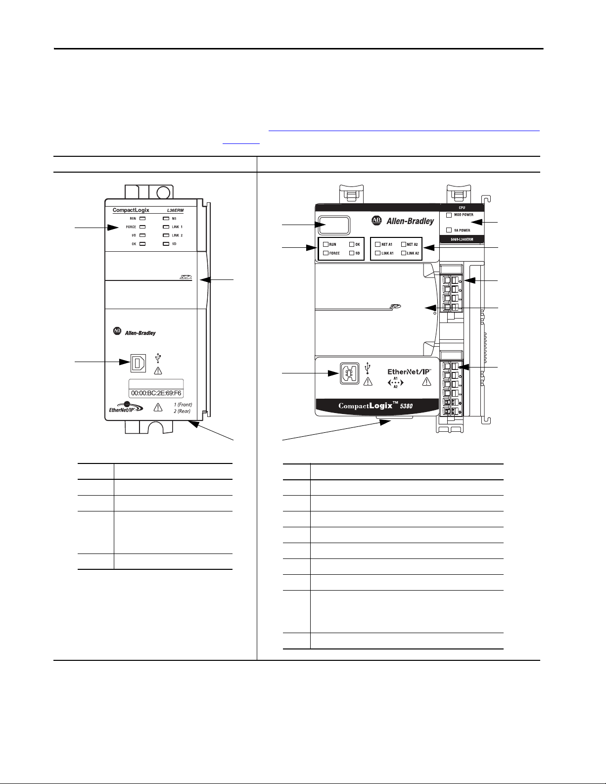
Replacement Considerations with CompactLogix and Compact GuardLogix Systems Chapter 3
Item Description
1 Status Indicators
2USB port
3 Behind the door:
• RUN REM PROG mode switch
• Reset button
•SD card slot
4 Ethernet ports 1 and 2
1
2
3
4
1
9
4
3
5
7
2
Item Description
14-character display
2 Controller Status Indicators
3USB port
4 Ethernet ports 1 and 2
5 Power Status Indicators
6 EtherNet/IP Status Indicators
7 MOD power connection
8 Behind the door:
• RUN REM PROG mode switch
• Reset button
•SD card slot
9 SA power connection
6
8
Connectors and Status Indicators
The following tables shows the differences between the connectors and status
indicators.
For more information on the controller status indicators and reset button, see
Chapter 8, Diagnostics and Status Indicators with CompactLogix Systems on
page 149.
CompactLogix 5370 L3 CompactLogix 5380
Rockwell Automation Publication 1756-RM100F-EN-P - October 2018 55

Chapter 3 Replacement Considerations with CompactLogix and Compact GuardLogix Systems
SAFETY
L36ERMS
CPU
SFTY RUN
SFTY TASK
SFTY LOCK
SFTY OK
Guard
Compact
Logix
Guard
Compact
Logix
1 (Front)
2 (Rear)
Item Description
1 Status Indicators
2 Behind the door:
• RUN REM PROG mode switch
• Reset button
•SD card slot
3USB port
4Ethernet ports 1 and 2
1
3
2
4
1
9
4
3
5
7
2
Item Description
14-character display
2 Controller Status Indicators
3USB port
4 Ethernet ports 1 and 2
5 Power Status Indicators
6 EtherNet/IP Status Indicators
7 MOD power connection
8 Behind the door:
• RUN REM PROG mode switch
• Reset button
•SD card slot
9 SA power connection
6
8
Compact GuardLogix 5370 Compact GuardLogix 5380
56 Rockwell Automation Publication 1756-RM100F-EN-P - October 2018

Replacement Considerations with CompactLogix and Compact GuardLogix Systems Chapter 3
Power the Controller
There are differences in how to power the 5380 controllers versus the 5370
controllers. Ta b l e 1 0
highlights some of the power differences.
For information on how to power your system, see the
CompactLogix 5380 and Compact GuardLogix 5380 Controllers User
Manual, publication 5069-UM001
Table 10 - Power Differences
CompactLogix 5370 L3 System,
Compact GuardLogix 5370 L3 System
Power source Compact I/O power supply External power supply
Power source location Power supply that is installed in the
system
The power supply location is based on the
requirements of the modules in the
system.
Power types provided System-side power only • System-side power via MOD Power RTB
Current type provided AC or DC as dictated by system design • System-side power - DC only
Special requirement • Must meet Power Supply Distance
Rating requirements
• Must track power consumption in the
local bank and on both sides of the
power supply
CompactLogix 5380 System Compact GuardLogix 5380 System
Separate from the system and connected to RTBs on controller
The modules installed in the system do not impact the power supply location. Power is transferred to the
system via removable terminal blocks (RTBs) on the controller.
• Field-side power via SA Power RTB
IMPORTANT: RTBs do not ship with the controller. The RTBs are available in kits that you must order
separately.
Kit 5069-RTB64-SCREW contains screw-type RTBs that are used for MOD power and SA power.
Kit 5069-RTB64-SPRING contains spring-type RTBs that are used for MOD power and SA power.
• Field-side power - AC or DC as dictated by
system design
• Must track the system-side and field-side power consumption to properly size the external power
supplies that provide each power type.
• Must use 5069-FPD, Field Potential Distributor if SA Power consumption is exceeded before reaching
max of 31 local I/O modules.
• Must use Field Potential Distribution module to change SA Power potential between AC and DC.
.
• System-side power - DC only
• Field-side power - DC only at the controller, AC
only through the use of a local 5069-FPD, Field
Potential Distributor module.
Rockwell Automation Publication 1756-RM100F-EN-P - October 2018 57

Chapter 3 Replacement Considerations with CompactLogix and Compact GuardLogix Systems
Project Size
Configure the Controller
The Logix Designer application uses the .ACD file format type with controller
projects. The project file size does not reflect the size of your project that
downloads to the controller. The .ACD file contains multiple components.
Not all components are downloaded to the controller.
You must consider the best way to use controller resources when
CompactLogix controllers communicate over an EtherNet/IP network. There
are limitations regarding how much EtherNet/IP communication the
controller supports.
Consider the following:
•Connections
•Ethernet Nodes
Connections Overview
A Logix 5000™ controller provides connection resources whenever
communications are established between two devices.
Connections are used when the system contains the following conditions
or activities:
• I/O modules, communication modules, and adapters are present in the
I/O configuration of the user project
• Produced or Consumed tags are configured in the user project
• Connected Messages are executed in the user application
• External devices, programming terminals, or HMIs communicate with
the controller
58 Rockwell Automation Publication 1756-RM100F-EN-P - October 2018

Replacement Considerations with CompactLogix and Compact GuardLogix Systems Chapter 3
Nodes on an EtherNet/IP Network
When used in a Logix Designer application project, 5380 and 5370 controllers
offer a simplified method for counting controller resources.
When you configure a 5380 control system, you simply count the number of
Ethernet nodes that you include in the I/O configuration section of your Logix
Designer application project.
On the Controller Properties dialog box, the Logix Designer application
project displays the updated number of nodes that are used as you add Ethernet
nodes to the project.
To see an example of how the project displays the node count, see Figure 12 on
page 65.
For the EtherNet/IP node limits for 5380 and 5370 controllers, see:
• CompactLogix Controllers Product Comparison on page 47
• Compact GuardLogix Controllers Product Comparison on page 49
Devices Included in the Node Count
Any devices that you add directly to the I/O configuration section are counted
toward the node limits of the controller. The following are example devices
that must be counted:
• Remote communication adapters
• Devices with an embedded EtherNet/IP port, such as I/O modules,
drives, and linking devices
• Remote controllers when a produce/consume connection is established
between the two controllers
• HMI devices that are included in the I/O configuration tree
• Third-party devices that are directly connected to the EtherNet/IP
network
Devices Excluded from the Node Count
When you calculate the EtherNet/IP node limitation of a controller, do not
count devices that exist on the EtherNet/IP network but are not added to the
I/O configuration section.
The following devices are not added to the I/O configuration section and are
not counted among the number of nodes:
•Computer
• HMI that is not added to the I/O configuration section
•MSG instruction
• Standard Ethernet devices for which the controller uses a socket
interface to communicate
Rockwell Automation Publication 1756-RM100F-EN-P - October 2018 59

Chapter 3 Replacement Considerations with CompactLogix and Compact GuardLogix Systems
New Project Dialog Box
When you create a project with a 5380 controller, the New Project dialog box
appears. The dialog box provides standard controller settings, including
security settings. The information that is entered in this dialog box displays on
the Controller Properties General tab and Security Tab.
60 Rockwell Automation Publication 1756-RM100F-EN-P - October 2018

Replacement Considerations with CompactLogix and Compact GuardLogix Systems Chapter 3
Controller Properties
This table lists Controller Properties dialog box tabs and indicates how a tab is
different on a CompactLogix 5380 controller compared to a
CompactLogix 5370 L3 controller.
Controller
Properties Tab
General Same functionality as the 5370 controllers.
Major Faults Same functionality as the 5370 controllers.
Minor Faults Same functionality as the 5370 controllers.
Date/Time Same functionality as the 5370 controllers.
Advanced New parameter to enable Minor Overflow fault reporting. The System Overhead Time
SFC Execution Same functionality as the 5370 controllers.
Project Option to download custom properties when you download project documentation and
Nonvolatile Memory Same functionality as the 5370 controllers.
Memory (Logix
Designer application,
version 28)
Capacity (Logix
Designer application,
version 29 and later)
Internet Protocol Same functionality as the 5370 controllers.
Port Configuration Same functionality as the 5370 controllers.
Network Same functionality as the 5370 controllers.
Security Now has additional security parameters.
Alarm Log Not available for 5380 controllers in version 28.
Comments
Slice parameter was removed.
For more information, see page 62
extended properties.
For more information, see page 63
The tabs indicate the same information but are named differently between the Logix
Designer application versions.
Indicates data usage. Data usage is indicated with one value that combines Data and
Logic memory usage and I/O memory usage.
See Memory Tab on page 64 or Capacity Tab on page 65.
For more information, see page 66
Available in version 29 or later with the same functionality as the 5370 controllers.
.
.
.
Rockwell Automation Publication 1756-RM100F-EN-P - October 2018 61

Chapter 3 Replacement Considerations with CompactLogix and Compact GuardLogix Systems
Report Overflow Faults is ena bled by default when
morphing a legacy project, but defaults to disabled
when creating a CompactLogix 5380 project.
Advanced Tab
The Advanced tab provides a way to assign the Controller Fault Handler and
Power-up Handler. You can also match a project to a specific controller by
serial number. The tab is used when the project is offline.
• Report Overflow Faults is a new parameter that lets you control Minor
Overflow fault reporting. When you create a project, the default setting
is disabled. When you import or open a legacy project, the default
setting is enabled. For more information, see Minor Fault on Overflow
on page 128.
• System Overhead Time Slice is no longer required for 5380 controllers,
and the parameter is removed.
Figure 9 - Controller Properties Dialog Box - Advanced Tab
5370 Controllers 5380 Controllers
62 Rockwell Automation Publication 1756-RM100F-EN-P - October 2018

Replacement Considerations with CompactLogix and Compact GuardLogix Systems Chapter 3
Project Tab
The Project tab provides general project information and lets you configure
project download and pass-through display parameters.
The tab is used when the project is offline.
Figure 10 - Controller Properties Dialog Box - Project Tab
5370 Controllers 5380 Controllers
Rockwell Automation Publication 1756-RM100F-EN-P - October 2018 63
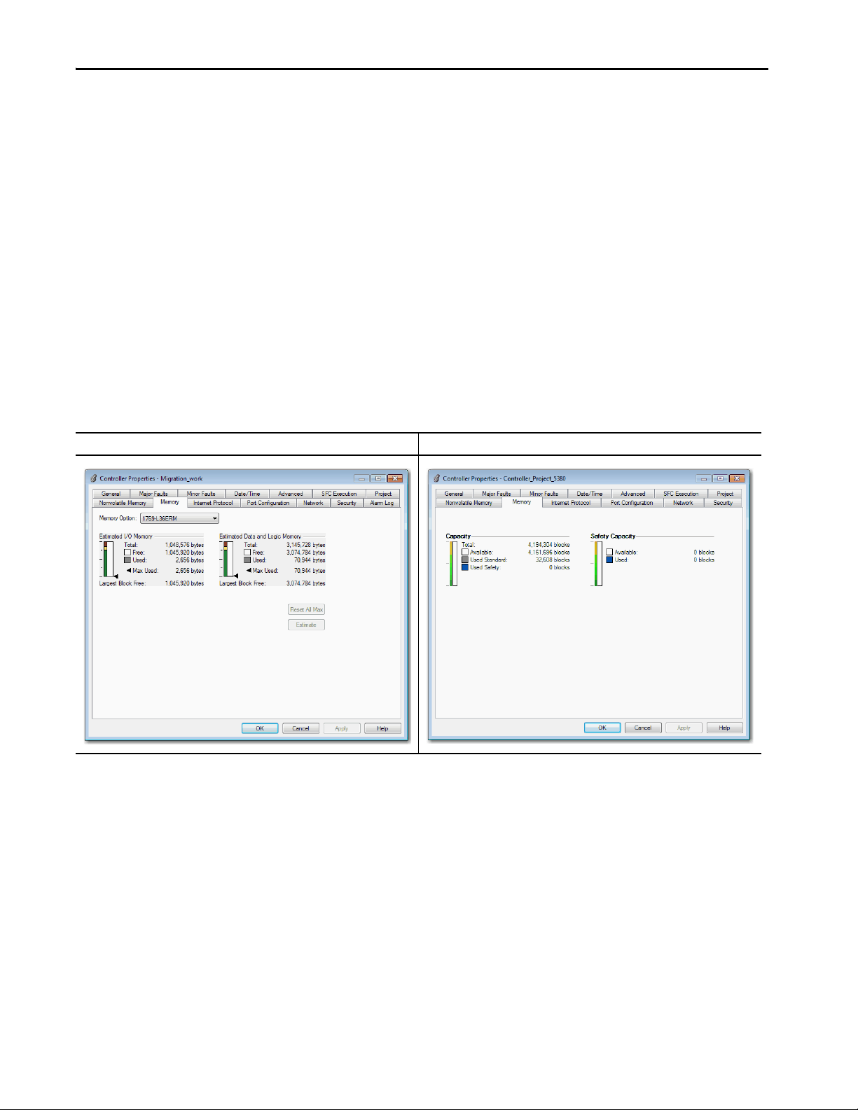
Chapter 3 Replacement Considerations with CompactLogix and Compact GuardLogix Systems
Memory Tab
In the Logix Designer application, version 28 or earlier, the Memory tab
indicates data usage.
• 5370 controllers - Data usage is indicated with two values. The tab
shows I/O memory and Data and Logic memory separately.
As you change the project, you can click Estimate to see the estimated
memory usage and remaining available memory.
• 5380 controllers - Data usage is indicated with one value that combines
Data and Logic memory usage and I/O memory usage.
As you change the project, the data values are automatically updated to
indicate the estimated memory usage and remaining available memory.
Figure 11 - Controller Properties Dialog Box - Memory Tab
CompactLogix 5370 L3 Version 28 Example CompactLogix 5380 Version 28 Example
64 Rockwell Automation Publication 1756-RM100F-EN-P - October 2018

Replacement Considerations with CompactLogix and Compact GuardLogix Systems Chapter 3
Capacity Tab
In the Logix Designer application, version 29 or later, the Capacity tab
indicates data and Ethernet node usage. This tab was named Memory in
previous versions of the Logix Designer application.
• 5370 controllers - Data usage is indicated with two values. The tab
shows I/O memory and Data and Logic memory separately. The tab also
shows the number of Ethernet nodes that are used.
As you change the project, you can click Estimate to see the estimated
memory usage and remaining available memory. The number of
Ethernet nodes is updated automatically, however.
• 5380 controllers - Data usage is indicated with one value that combines
Data and Logic memory usage and I/O memory usage. The tab also
shows the number of Ethernet nodes that are used.
As you change the project, the data values are automatically updated to
indicate the estimated memory usage and remaining available memory.
The number of Ethernet nodes is also updated automatically.
As you change the project, the data values are automatically updated.
Figure 12 - Controller Properties Dialog Box - Capacity Tab
5370 Controllers 5380 Controllers
Rockwell Automation Publication 1756-RM100F-EN-P - October 2018 65
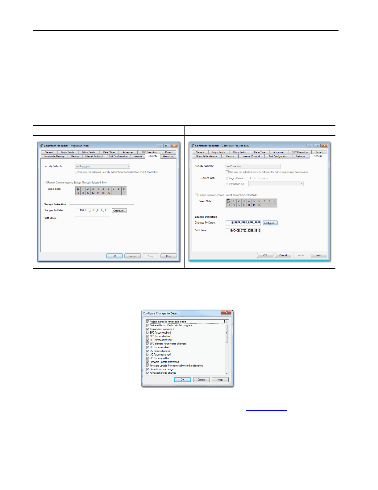
Chapter 3 Replacement Considerations with CompactLogix and Compact GuardLogix Systems
Security Tab
The Security Tab lets you see the controller security settings, for example, the
Security Authority choice. Security settings are configured when you create the
project.
With the Logix Designer application, version 28 or later, the controllers
support additional parameters in the Security Authority section.
Figure 13 - Controller Properties Dialog Box - Security Tab
5370 Controllers 5380 Controllers
Click the Configure button to access the Configure Changes to Detect dialog
box. Use the dialog box to choose the events you wish to monitor or ignore in
the controller.
For more information on Security settings, see the FactoryTalk® Security
System Configuration Guide, publication FTSEC-QS001
.
66 Rockwell Automation Publication 1756-RM100F-EN-P - October 2018
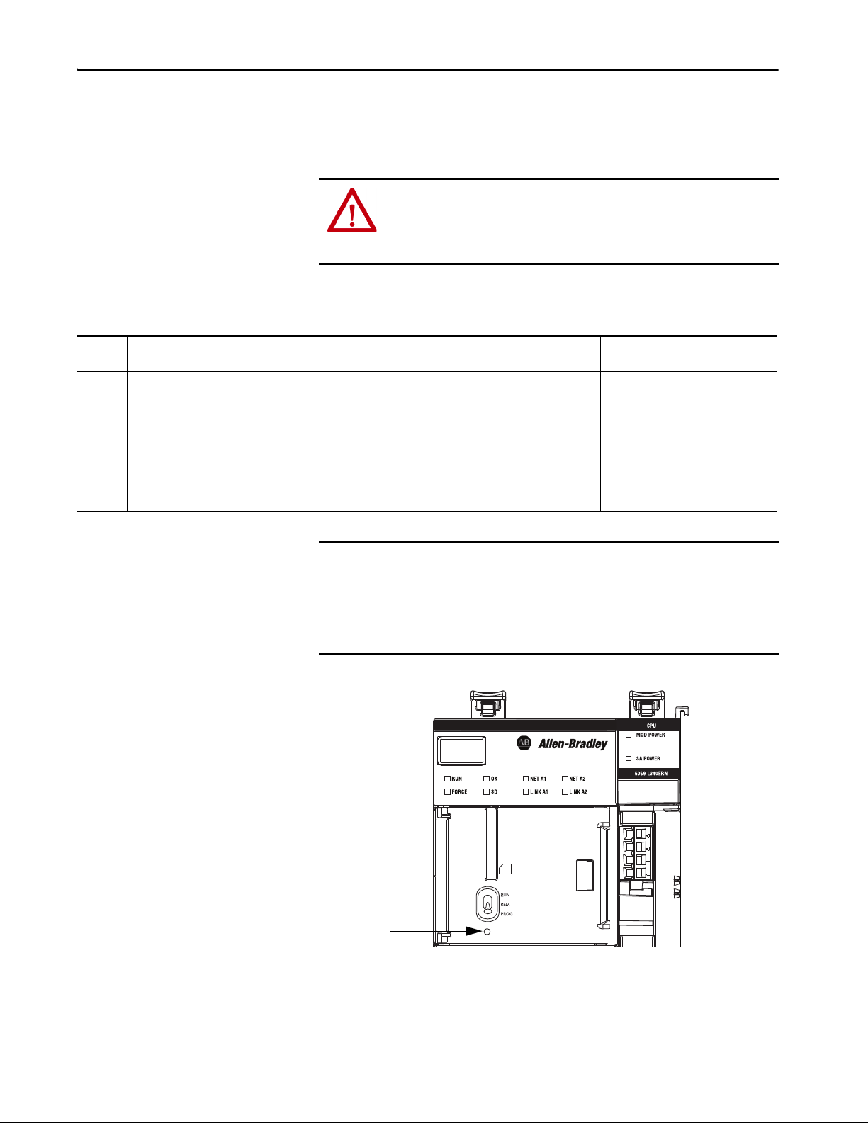
Replacement Considerations with CompactLogix and Compact GuardLogix Systems Chapter 3
Reset Button
Controller Reset Button
You can reset the controller with the reset button behind the front door on the
controller. You press the button in and hold it during a controller power-up
sequence to reset the controller.
Ta b l e 1 1
Table 11 - Reset Button Descriptions
Reset
Stage
Stage 1 A Stage 1 reset clears the application program and memory, but
Stage 2 A Stage 2 reset returns the controller to out-of box settings, including
Definition 5370 Controllers 5380 Controllers
retains the IP address and all object attributes designated as
non-volatile.
A Stage 1 reset occurs only if the controller contains a user
application.
firmware, and clears all network settings.
A Stage 2 reset occurs only if the controller does not contain a user
application, and the current controller firmware is not a 1.x revision.
describes the differences between the reset stages.
WARNING: When you press the reset button while power is on, an Electric
Arc can occur. This could cause an explosion in hazardous location
installations. Be sure that power is removed or the area is nonhazardous
before proceeding.
Supported Supported
Not supported Supported
IMPORTANT Remember the following:
• Because port enable/disable status is associated with the application
program, ports become enabled after a Stage 1 reset.
• A reset occurs only when you hold the button while the module powers
up. If you press the reset button during runtime, there is no effect.
Figure 14 - 5380 Controllers - Reset Button
For information on how to use the reset button, see the CompactLogix 5380
and Compact GuardLogix 5380 Controllers User Manual, publication
5069-UM001
Rockwell Automation Publication 1756-RM100F-EN-P - October 2018 67
.
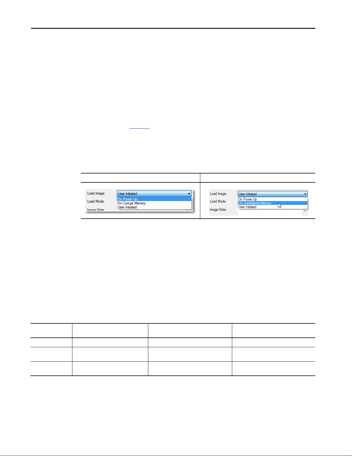
Chapter 3 Replacement Considerations with CompactLogix and Compact GuardLogix Systems
SD Card Behavior
The controller has changed some behavior when loading a project from the SD
card into a controller. The changes facilitate an easier commissioning of new,
out-of box controllers. All Logix 5000 controllers ship from the factory with
firmware revision 1.x.
With 5380 controllers, the Load Image setting On Uninitialized Memory is
available. This setting replaces the On Corrupt Memory setting that is available
with 5370 controllers.
The general behavior is the same for both settings. The only difference is the
controller behavior when it is in the out-of-box condition, as described in
Ta b l e 1 2
.
You can install an SD card that uses On Uninitialized Memory in an out-of the
box controller, that is, one that uses firmware revision 1.x. In this case, at
power-up the image loads both the controller firmware and controller
application.
5370 Controllers 5380 Controllers
When you use an SD card with an image in an out-of-box controller (firmware
revision 1.x), at power-up that controller updates its firmware to the revision
stored on the card. The update occurs regardless of the Load Image setting for
the image on the SD card.
The On Power Up, and On Initialized Memory settings also load the
controller application into an out-of box controller.
This table shows what happens at power-up when you insert an SD card that
contains an image into a CompactLogix 5380 and Compact GuardLogix 5380
controller.
Table 12 - SD Card Settings and Controller Power-up Behavior
Image Setting Controller is in Out-of-Box Condition
User Initiated Loads Firmware Only
On Power Up Loads both Firmware and Application • Loads Firmware if there is a revision mismatch
On Uninitialized
Memory
(1) Indicates change in behavior from CompactLogix 5370 L3 and older controllers.
(2) “Valid” includes the No Project condition.
(Firmware Revision 1.x)
(1)
Loads both Firmware and Application
Firmware > 1.x and Internal Nonvolatile
Memory is Not Valid
Does Nothing Does Nothing
• Loads Application
(1)
• Loads Firmware if there is a revision mismatch
• Loads Application
(2)
Firmware > 1.x and Internal Nonvolatile
Memory is Valid
• Loads Firmware if there is a revision mismatch
• Loads Application
Does Nothing
(2)
68 Rockwell Automation Publication 1756-RM100F-EN-P - October 2018
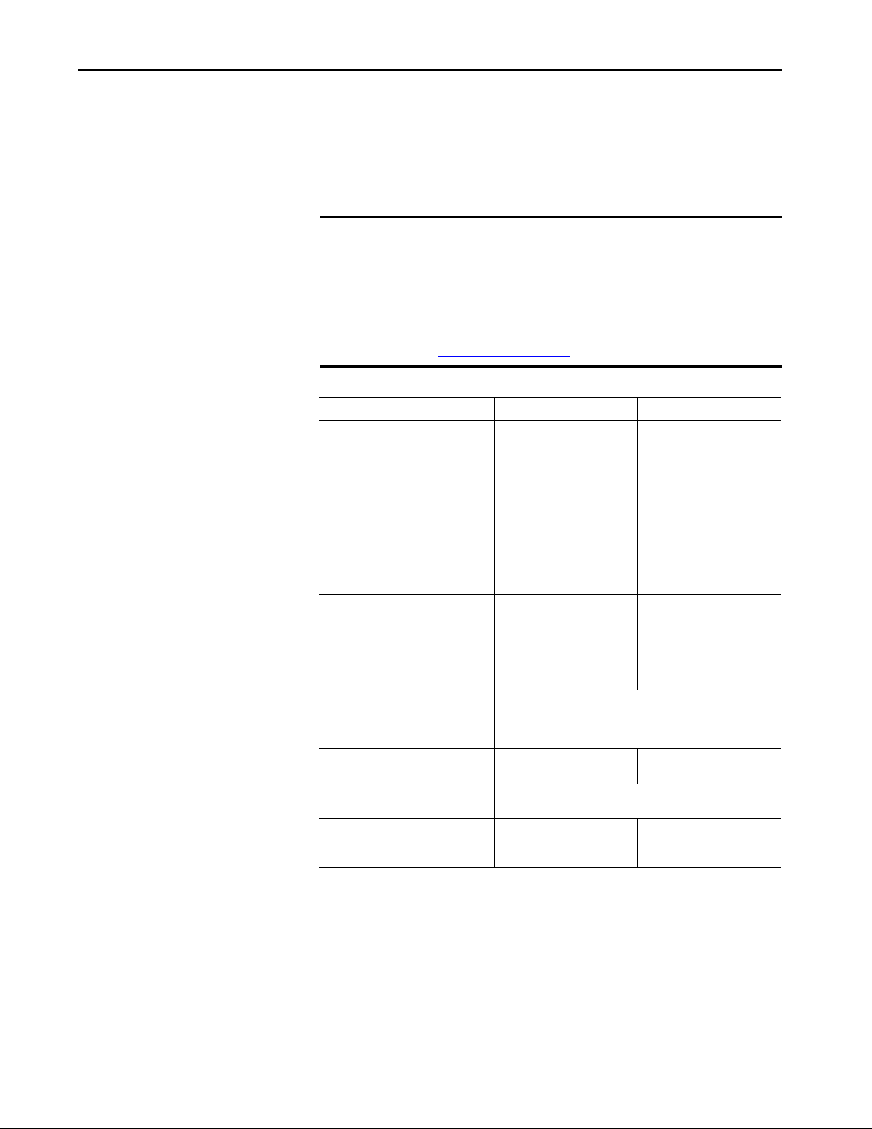
Replacement Considerations with CompactLogix and Compact GuardLogix Systems Chapter 3
Communication Options
CompactLogix 5380 and Compact GuardLogix 5380 controllers can operate
on EtherNet/IP networks.
CompactLogix 5370 L3 and Compact GuardLogix 5370 L3 controllers can
operate on EtherNet/IP and DeviceNet networks.
IMPORTANT Be aware of the following:
• The 5380 controllers do not support for half-duplex communications on
Ethernet at any speed.
• We recommend that you consider some factors that affect how to set
EtherNet/IP network communication rate in your application during
design. For more information, see Network Communication Rate
Considerations on page 169.
Application Type 5370 Controllers Support 5380 Controllers Support
Network communication option • EtherNet/IP
• DeviceNet via a 1769-SDN
scanner
• 1769-ASCII module for an
ASCII serial interface to RS232, RS-422 and RS-485
devices
• 1769-SM2 module for a
Modbus RTU serial interface
• MVI69-MNET for Modbus TCP/
IP interface
EtherNet/IP mode options Can be used in linear, DLR, and
Integrated Motion EtherNet/IP
Time Synchronization EtherNet/IP - Available with Integrated Motion and non-motion
Control of distributed I/O • EtherNet/IP
Produce/consume data between
controllers
Messaging to and from other devices,
including access to the controller via Logix
Designer application
star topologies.
Does not support for Dual-IP
mode.
applications
• D eviceNet
EtherNet/IP
• EtherNet/IP
• DeviceNet (only to devices)
EtherNet/IP
•Linear/DLR mode
• Dual-IP mode - Available with
the Logix Designer
application, version 29 or later
Both modes can be used in l inear,
DLR, and star topologies.
EtherNet/IP
EtherNet/IP
Rockwell Automation Publication 1756-RM100F-EN-P - October 2018 69

Chapter 3 Replacement Considerations with CompactLogix and Compact GuardLogix Systems
Communication Throughput
Unlike 5370 controllers, which shares its main core between application code
and communications, the 5380 controllers run communications
asynchronously from the user application.
This implementation provides better communications throughput in both the
bandwidth and speed of data the 5380 controller can deliver to and from, for
example, HMIs, Historians, and MES systems. It also improves the overall
application performance as the controller no longer has to task switch and
pause application execution to handle HMI or other class 3 traffic.
Because the controller runs communications asynchronously to the
application, make sure communications that are delivered to the controller are
complete before the application executes on the newly delivered data. This
practice applies to both data that comes into the controller and data that
goes out.
For example, if the HMI is writing a large block of recipe data to the controller,
application code can start executing on that recipe data before the data writing
process finishes. This action results in half of the current recipe and half of the
last recipe in the application space.
Traditionally, programmers have used the following techniques to control the
effects of asynchronous communications:
•UID/UIE pairs
•Periodic tasks
•Moving data with CPS instructions
The techniques all rely on controlling when the main core can switch tasks,
thus helping to prevent the communications task from changing data while the
control task used it. Because the 5380 controller processes communications on
an independent core of the CPU, then UID/UIE pairs and Periodic Tasks are
not as effective in all cases.
70 Rockwell Automation Publication 1756-RM100F-EN-P - October 2018

Replacement Considerations with CompactLogix and Compact GuardLogix Systems Chapter 3
The items that are highlighted in this table are where 5370 and older
controllers and the 5380 controllers behavior differ.
Table 13 - Behavior Differences
Tag Acce ss
Tag Rea d/
Write Source
HMI Allows Blocks Blocks Blocks Allows Blocks
MSG Allows Blocks Blocks Blocks Allows Blocks
I/O Update Allows Allows Blocks Blocks Allows Allows
Produce/
Consu me
Other User
Tas k s
Motion
Planner
Blocks - Prevents source data values from change by communications during application execution.
Allows - Communications can change source data values during application execution.
5380 Controllers 5370 Controllers 5380 Controllers 5370 Controllers 5380 Controllers 5370 Controllers
Allows Allows Blocks Blocks Allows Allows
Blocks Blocks Blocks Blocks Allows Allows
Allows Allows Blocks Blocks Allows Allows
UID/UIE CPS Periodic Task
Because the 5370 and 5380 controllers have 32-bit data integrity, this only
applies to data structures larger than 32 bits. If word-level integrity is your
primary concern, the 32-bit data integrity does not impact your data use.
Good programming practice dictates the use of two unique words at the
beginning and the end of data. The controller validates the words to assure the
entire structure has data integrity. We recommend that the handshake data is
changed and the application code validates it every transaction before the
controller application code or higher-level system reading controller data acts
on it.
Rockwell Automation Publication 1756-RM100F-EN-P - October 2018 71

Chapter 3 Replacement Considerations with CompactLogix and Compact GuardLogix Systems
CompactLogix 5380 Controller
Compact 5000 I/O Modules
5069-AEN2TR Adapter
Compact 5000 I/O Modules
PanelView™ Plus 7 Terminal
Stratix® 2000 Switch
PowerFlex® 527 Drive
Enterprise-level
Network
Device-level Network
In this example, all network
communication occurs at
the 100 Mbps.
EtherNet/IP Modes
With the Logix Designer application, version 29 or later, 5380 controllers
support the following EtherNet/IP modes:
• Dual-IP Mode
• Linear/DLR Mode
For more information on how to use EtherNet/IP modes, see the
CompactLogix 5380 and Compact GuardLogix 5380 Controllers User
Manual, publication 5069-UM001
.
Dual-IP Mode
With the Logix Designer application, version 29 or later, you can use Dual-IP
mode.
Dual-IP mode lets you configure the controller embedded Ethernet ports to
connect to separate networks, that is, an enterprise-level Ethernet network and
a device-level network.
The following graphic shows a CompactLogix 5380 controller that uses
Dual-IP mode in a star topology. For more examples of how to use the
controllers that use Dual-IP mode in EtherNet/IP topologies, see Dual-IP
Mode in EtherNet/IP Topologies on page 173.
F1
F2
F3
F4
F5
F6
F7
F8
F9
F10
F11
F12
F13
F14
F15
F16
527
72 Rockwell Automation Publication 1756-RM100F-EN-P - October 2018

Replacement Considerations with CompactLogix and Compact GuardLogix Systems Chapter 3
527
F1
F2
F3
F4
F5
F6
F7
F8
F9
F10
F11
F12
F13
F14
F15
F16
CompactLogix 5380 Controller
Compact 5000 I/O Modules
5069-AEN2TR Adapter
Compact 5000 I/O Modules
PanelView Plus 7 Terminal
PowerFlex 527 Drive
In this example, all network
communicat ion occurs at
the 100 Mbps.
Linear/DLR Mode
When the controllers operate in Linear/DLR mode, they can only connect to
one network and have only one network configuration. The controllers can
connect to any EtherNet/IP topology.
Rockwell Automation Publication 1756-RM100F-EN-P - October 2018 73

Chapter 3 Replacement Considerations with CompactLogix and Compact GuardLogix Systems
Use I/O Modules in CompactLogix Systems
You can use local and remote I/O modules with the controllers.
The following is information about how you can use I/O modules in
different applications.
5370 Application 5380 Application
Local I/O modules 1769 Compact I/O modules across up to
Number of local I/O
modules supported,
max
Installation location of
local I/O modules
Installation orientation
of local I/O modules
Spacing on all sides of
system, min
For more information
see, Controller Spacing
on page 51
Remote I/O modules Accessible over the following:
Special considerations • Consider the number and type of
(1) When you use this controller with the Logix Designer application, version 29.00.00, the application limits the number of local
I/O modules in the project to 16. For more information, see the Rockwell Automation® Knowledgebase article #942580, ‘5380
CompactLogix controllers limited to 16 local 5069 modules in V29 of Studio 5000®.’ The document is available at http://
www.rockwellautomation.com/knowledgebase.
With the Logix Designer application, version 30.00.00 or later, the controller supports as many as 31 local I/O modules.
three banks
• 1769-L30ER, 1769-L30ER-NSE,
1769-L30ERM, 1769-L30ERMS: 8
• 1769-L33ER, 1769-L33ERM,
1769-L33ERMS: 16
• 1769-L36ERM, 1769-L36ERMS: 30
Across as many as three banks, the bank
containing the controller and two
expansion banks
• I/O modules are only installed in the
local bank - Horizontal only
• I/O modules are installed in multiple
banks - Horizontal or vertical
50 mm (2 in.) of space on all sides Varies based on the
• EtherNet/IP network
• DeviceNet network via 1769-SDN
adapter
The controllers cannot access Compact
5000 I/O.
1769 Compact I/O modules in a system
when you set the requested packet
interval (RPI) rate
• Track collective system power use by
the local I/O modules
• Consider the power supply distance
rating when you plan the slot location
for local I/O modules
Compact 5000 I/O modules in one bank
• 5069-L306ER, 5069-L306ERM,
5069-L310ER, 5069-L310ER-NSE,
5069-L310ERM: 8
• 5069-L320ER, 5069-L320ERM: 16
• 5069-L330ER
5069-L340ER, 5069-L340ERM,
5069-L350ERM, 5069-L380ERM,
5069-L3100ERM: 31
Same bank as the controller
Horizontal only
operating temperature:
• 50.80 mm (2.00 in.) at 55 °C (131 °F)
• 101.66 mm (4.00 in.) at 60 °C (140 °F)
Accessible over an EtherNet/IP network
For optimal CompactLogix 5380 control
system performance, we recommend that
you use Compact 5000 I/O modules as the
remote I/O modules.
Track collective SA power use by the local
I/O modules in a system
(1)
, 5069-L330ERM,
74 Rockwell Automation Publication 1756-RM100F-EN-P - October 2018

Replacement Considerations with CompactLogix and Compact GuardLogix Systems Chapter 3
1
2
34
56
78
CompactLogix 5370 L3 Controller
1769 Compact I/O Modules
1769-AENTR Adapter
1769 Compact I/O Modules
1734-AENTR Adapter
1734 POINT I/O Modules
Stratix 6000 Switch
Kinetix 350 Drive
Work stat ion
Remote I/O
Modules
Local I/O Modules
Bank 1 Bank 2 Bank 3
02
0
1734-AENTR
Module
Status
Network
Activity
Network
Status
Point Bus
Status
System
Power
Field
Power
POINT I O
Link 1
Activity/
Status
Link 2
Activity/
Status
IP ADDRESS
527
F1
F2
F3
F4
F5
F6
F7
F8
F9
F10
F11
F12
F13
F14
F15
F16
Compac tLogix 5380 Controller
Compact 5000 I/O Modules
5069-AEN2TR Adapter
Compact 5000 I/O Modules
1734-AENTR Adapter
1734 POINT I/O™ Modules
PanelView Plus 7
Terminal
Stratix 5700 Switch
PowerFlex 527 Drive
Kinetix® 5500 Drive
Work stat ion
Remote I/O Modules
Local I/O Modules
CompactLogix 5370 L3 System
The following shows I/O modules used in CompactLogix 5370 L3 system.
CompactLogix 5380 System
The following shows I/O modules in a CompactLogix 5380 system.
Rockwell Automation Publication 1756-RM100F-EN-P - October 2018 75

Chapter 3 Replacement Considerations with CompactLogix and Compact GuardLogix Systems
Local I/O Module Performance
Local I/O module performance is significantly improved in 5380 systems
when compared to 5370 systems. The improved performance results from the
following:
• A high-performance, multi-core processor architecture
• High-speed Compact 5000 I/O system backplane supports faster
transfer rates
In 5370 systems, local I/O module updates are transferred to the controller via
the 1769 CompactBus at the specified requested packet interval (RPI). The
controller uses a dedicated I/O task to update internal I/O tag data. The task is
internally set to a priority of level 6. You must carefully arrange user task
priorities so that important local I/O updates are not interrupted by scanning
of lower-level tasks in the controller.
With the high-performance 5380 controller, you are no longer required to
arrange task priorities around the dedicated I/O task. The I/O tag data is
updated as part of an internal task on its own processor core and does not affect
the user tasks running on the controller processor core.
System performance is also improved because you can configure much faster
RPI rates with Compact 5000 I/O modules. For example, you can configure
the RPI to occur as fast as every 200 μs. You cannot use the same rate with the
1769 Compact I/O modules that are used in 5370 systems.
Finally, the backplane is optimized to move larger amounts of data in one
packet than is possible on the 1769 CompactBus backplane.
Logix 5000 controllers still scan for I/O updates at the RPI asynchronously to
the program scan. The 5380 system handles controller multi-tasking and I/O
updates more efficiently and faster than 5370 systems, though. The enhanced
performance results from improvements to the architecture, hardware, and
system backplane.
When you use 5380 systems, there are fewer configuration considerations and
a much better screw-to-screw I/O performance compared to 5370 systems that
use local 1769 Compact I/O.
76 Rockwell Automation Publication 1756-RM100F-EN-P - October 2018

Replacement Considerations with CompactLogix and Compact GuardLogix Systems Chapter 3
Event Task Triggers
You can use event task triggers in 5380 systems to optimize local I/O
performance and screw-to-screw times. An event task, if configured correctly,
interrupts all other tasks for the minimum amount of time that is required to
respond to the event.
You can now configure event triggers on I/O data change of state with
Compact 5000 I/O fast input modules. This option is not available with 5370
controllers because the 1769 Compact I/O modules do not support event
triggers on I/O data change of state. If the controller executes the immediate
output instruction (IOT) at the end of the event task, the output data is
transmitted immediately. The controller does not have to wait for processing at
the next RPI.
The table shows an updated comparison of event triggers with 5380 and 5370
controllers. Consult Logix 5000 Controllers Tasks, Programs, and Routines
Programming Manual, publication 1756-PM005 for considerations that can
affect the execution of an event task.
Event task triggers supported
Controllers
5370 controllers XXXXX
5380 controllers XXXXXX
Module Input Data
State Change
Consumed Tag Axis Registration 1
or 2
Axis Watch Motion Group
Execution
EVENT instruction
For more information on how to use event triggers with Compact 5000 I/O
fast input modules, see the 5000 Series Digital I/O Modules in Logix 5000
Control Systems User Manual, publication 5000-UM004
.
Rockwell Automation Publication 1756-RM100F-EN-P - October 2018 77

Chapter 3 Replacement Considerations with CompactLogix and Compact GuardLogix Systems
Scheduled Outputs
New with 5380 controllers and Compact 5000 I/O fast modules is the option
to schedule outputs and time stamp inputs to a grandmaster clock within a CIP
Sync™ system. CIP Sync technology supports highly distributed applications
that require the following :
• Timestamping
• Sequence of Events recording
• Distributed motion control
• Increased control coordination
This level of control is not available with 5370 controllers because you cannot
configure 1769 Compact I/O modules with scheduled outputs or
timestamped inputs.
For more information on how to use scheduled outputs with
Compact 5000 I/O fast output modules, see the 5000 Series Digital I/O
Modules in Logix 5000 Control Systems User Manual, publication 5000-
UM004.
You can use the following to obtain an ideal midrange solution for applications
that use Integrated Motion Over an EtherNet/IP network:
• 5380 controllers
• Compact 5000 I/O fast I/O modules
• Kinetix 5500 servo drives
78 Rockwell Automation Publication 1756-RM100F-EN-P - October 2018

Replacement Considerations with CompactLogix and Compact GuardLogix Systems Chapter 3
Build Button
Download the Program to the Controller
The first time that you download a program, it can take longer than subsequent
downloads. These situations can affect download/compile times:
• The capability of the personal computer or laptop.
• You download the project immediately after a project import or upload,
but before Logix Designer has compiled the project once.
• You edit a User Defined Tag (UDT), Add-On Instruction (AOI), or an
object that is used in many places.
• Increased load when Logix Designer compiles and generates code.
Build Button
The new Build button in Logix Designer creates binary files that are compiled
from user subroutines, and caches them in the project .ACD file.
If these files are present in the project during a download, then Logix Designer
does not have to recompile them, and saves time during the download process.
Every download requires that only the changed subroutines must be
recompiled. You can perform a build offline, save the project .ACD file, and
later distribute it to many controllers without recompilation.
This manual build step is optional. If you do not use the build button, Logix
Designer builds all necessary files when you initiate a download.
An imported project requires a complete rebuild, and extends the download
process the first time you attempt a download.
Downloading Workflow Change on page 80
download changes for 5380 controllers.
provides an explanation of the
Rockwell Automation Publication 1756-RM100F-EN-P - October 2018 79

Chapter 3 Replacement Considerations with CompactLogix and Compact GuardLogix Systems
Downloading Workflow Change
Offline builds can save time when doing subsequent downloads.
5380 Controllers 5370 Controller
Only changed source code is recompiled on a download. All projects had their source code recompiled on ever y
Mitigation
Adjust your workflow to save workstations from having to rebuild the project.
You can do offline builds, save the project file, and distribute it to other
workstations to minimize your download times.
Upload Fidelity Change
When you upload, projects that contain program parameters and aliases now
are faithfully reproduced. The uploaded RLL source code is an exact replica of
what was downloaded. 5370 controller RLL subroutines that referenced aliases
or program parameters are not reproduced as faithfully.
download.
80 Rockwell Automation Publication 1756-RM100F-EN-P - October 2018
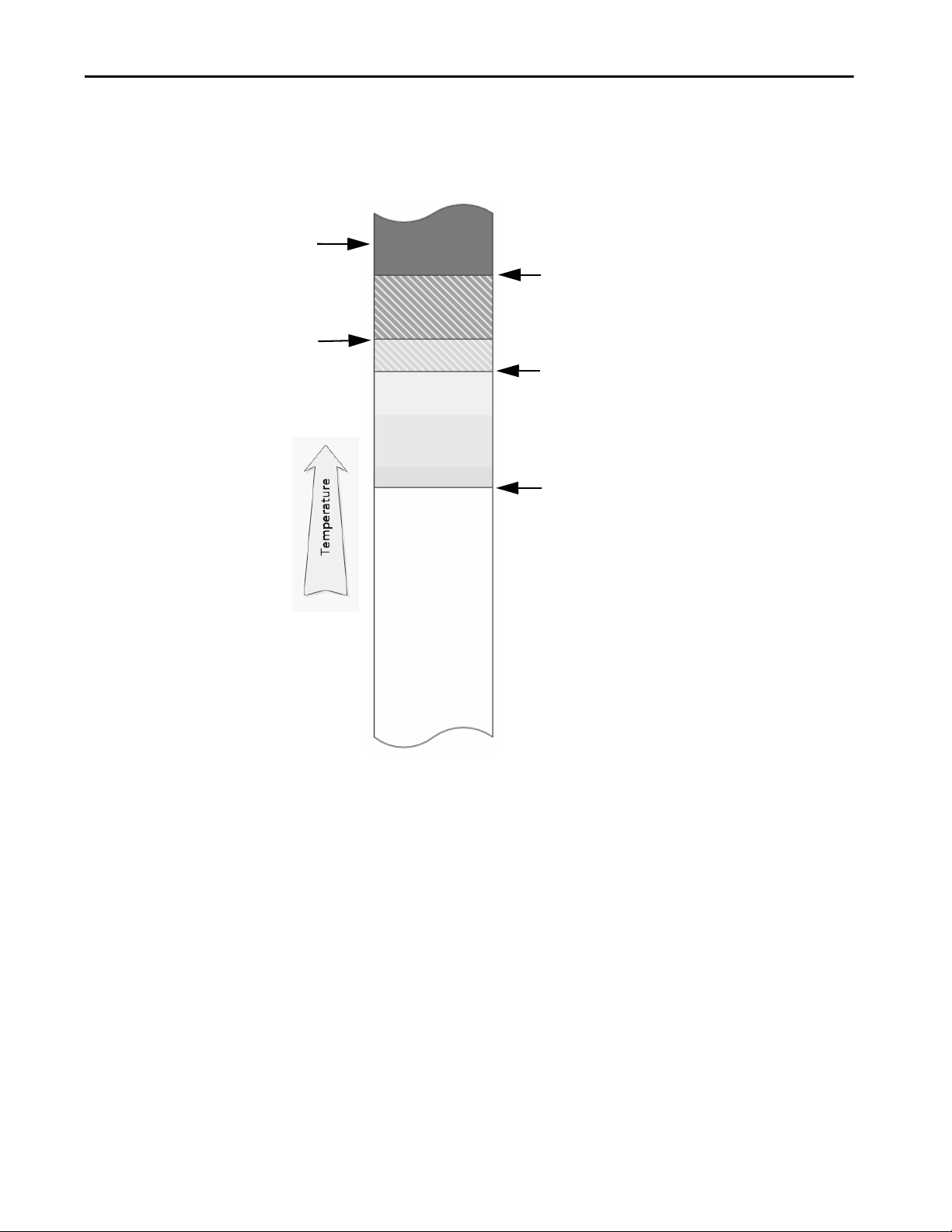
Replacement Considerations with CompactLogix and Compact GuardLogix Systems Chapter 3
Threshold for controller to declare a `Hardware Preservation
Fault’, and reset the module and disable power.
In the disabled power condition, only the OK status indicator is
illuminated, and it is red. The module does not apply power
until it has cooled below the Hardware Preservation Hysteresis
limit. The module then enters fault mode, records the fault in
the major fault log, and displays `CPU Temperature Fault’ on
the front panel.
Threshold for controller to declare a `CPU Temperature Fault’
major recoverable fault. If a fault handler does not clear the
fault, then the module enters fault mode, records the fault in
the major fault log, and displays `T17:C34 CPU Temperature
Fault’ on the front panel.
Threshold for controller to declare a `T17:C35 Controller internal
temperature is approaching operating limit’ minor fault and set
the Diagnostics minor fault bit.
The fault is recorded in the minor fault log, but is not displayed
on the front panel. If the temperature returns to an acceptable
range, the Diagnostics minor fault bit clears, but the minor fault
record remains.
Power to the
controller is
disabled
Hardware Preservat ion
Hysteresis Limit
Power does not
become enabled
when in this range
All power to the controller is disabled except
to run the red OK status indicator and
monitor the temperature.
Thermal Monitoring and Thermal Fault Behavior
The controllers monitor internal module temperatures and respond as the
temperature increases.
Figure 15 - Thermal Fault Behavior
Rockwell Automation Publication 1756-RM100F-EN-P - October 2018 81

Chapter 3 Replacement Considerations with CompactLogix and Compact GuardLogix Systems
Notes:
82 Rockwell Automation Publication 1756-RM100F-EN-P - October 2018

Chapter 4
Replacement Considerations with Safety
Applications
Topic Page
Perform Risk Assessment 83
Applications with 1734-AENTR Series A Modules 84
Safety Signature 84
Safety Network Number 86
Produce/Consume Safety Tags 87
Safety Application Conversion 88
Replace Producer Controller 94
This chapter describes features and functions that are associated with the
GuardLogix® 5580 and Compact GuardLogix 5380 controllers, and the
differences in safety functionality from previous safety controllers.
Perform Risk Assessment
A proper safety strategy consists of risk assessment and risk reduction.
• Risk Assessment – understand the machine limits and functions and
tasks that may be required to be performed at the machine throughout
its life.
• Risk Reduction – performed if necessary and safety measures are
selected based on the information derived from the risk assessment
stage. The manner in which this is done is the basis of the Safety Strategy
for the Machine.
Safety Standard IEC-61508 Part-1, Section 7.16 (Overall modification and
retrofit) states as follows:
7.16.2.3.- An impact analysis shall be carried out that shall include an
assessment of the impact of the proposed modification or retrofit
activity on the functional safety of any E/E/PE safety-related system.
The assessment shall include a hazard and risk analysis sufficient to
determine the breadth and depth to which subsequent overall, E/E/PE
system or software safety lifecycle phases will need to be undertaken.
The assessment shall also consider the impact of other concurrent
modification or retrofit activities, and shall also consider the functional
safety both during and after the modification and retrofit activities have
taken place.
See the Machinery Safebook 5 - Safety related control systems for machinery
Reference Manual, publication SAFEBK-RM002C-EN-P
Rockwell Automation Publication 1756-RM100F-EN-P - October 2018 83
.

Chapter 4 Replacement Considerations with Safety Applications
Applications with 1734-AENTR Series A Modules
Safety Signature
If your system includes 1734-AENTR Series A modules and you update to a
GuardLogix 5580 controller, reconnection events can result in a failure to
connect. The modules display error code 16#203 (connection time out) or
16#117 (invalid connection POINT). Rockwell Automation recommends
that you upgrade to 1734-AENTR Series B or later modules.
The safety signature consists of an ID number, date, and time that uniquely
identifies the safety portion of a project. This signature includes safety logic,
data, and configuration.
• Compact GuardLogix 5370 and GuardLogix 5570 controllers in SIL1
or SIL2 configuration did not require safety signature.
• Compact GuardLogix 5370 and GuardLogix 5570 controllers in a SIL3
configuration, required a safety signature.
• For Compact GuardLogix 5380 and GuardLogix 5580 controllers in a
SIL2 configuration (safety controller only), a safety signature is required
for up to SIL2.
• For GuardLogix 5580 controllers in a SIL3 configuration (primary
safety controller and safety partner), a safety signature is required.
For Compact GuardLogix 5380 and GuardLogix 5580 controllers, the safety
signature ID is now 256-bit.
Compact GuardLogix 5370 and GuardLogix 5570
Controllers Safety Signature ID
Compact GuardLogix 5380 and GuardLogix 5580 Controllers
Safety Signature ID
84 Rockwell Automation Publication 1756-RM100F-EN-P - October 2018

Replacement Considerations with Safety Applications Chapter 4
GSV of Safety Attributes
The two attributes below generate errors when imported into a Compact
GuardLogix 5380 or GuardLogix 5580 Controller project. These attributes no
longer exist in the Compact GuardLogix 5380 and GuardLogix 5580
Controllers.
Compact GuardLogix 5370 and GuardLogix 5570 Controllers only
SafetySignatureID (DINT) 32-bit identification number
SafetySignature (String) ID number plus date and time stamp
SafetySignatureID is changed to SafetySignatureIDLong or
SafetySignatureIDHex in the Compact GuardLogix 5380 and GuardLogix
5580 Controllers.
Compact GuardLogix 5380 and GuardLogix 5580 Controllers only
SafetySignatureIDLong (SINT [33]) The first byte is the size of the safety signature ID in bytes, and the
SafetySignatureIDHex (String) 64 character hexadecimal string representation of the safety signature ID.
SafetySignatureDateTime (String) 27 character date time of a safety signature in the format of mm/dd/yyyy,
remaining 32 bytes contain the content of the 32-byte safety signature ID.
hh:mm:ss.iii<Am or PM>
This example shows the SafetySignature after the import, and what to change
it to.
1. Compact GuardLogix 5370 and GuardLogix 5570 controllers have a
safety attribute called SafetySignature. Since this attribute does not exist
in Compact GuardLogix 5380 and GuardLogix 5580 controllers, this is
how the rung appears after the import.
2. When you change the SafteySignature attribute to the
SafetySignatureDateTime attribute, the rung compiles.
Rockwell Automation Publication 1756-RM100F-EN-P - October 2018 85
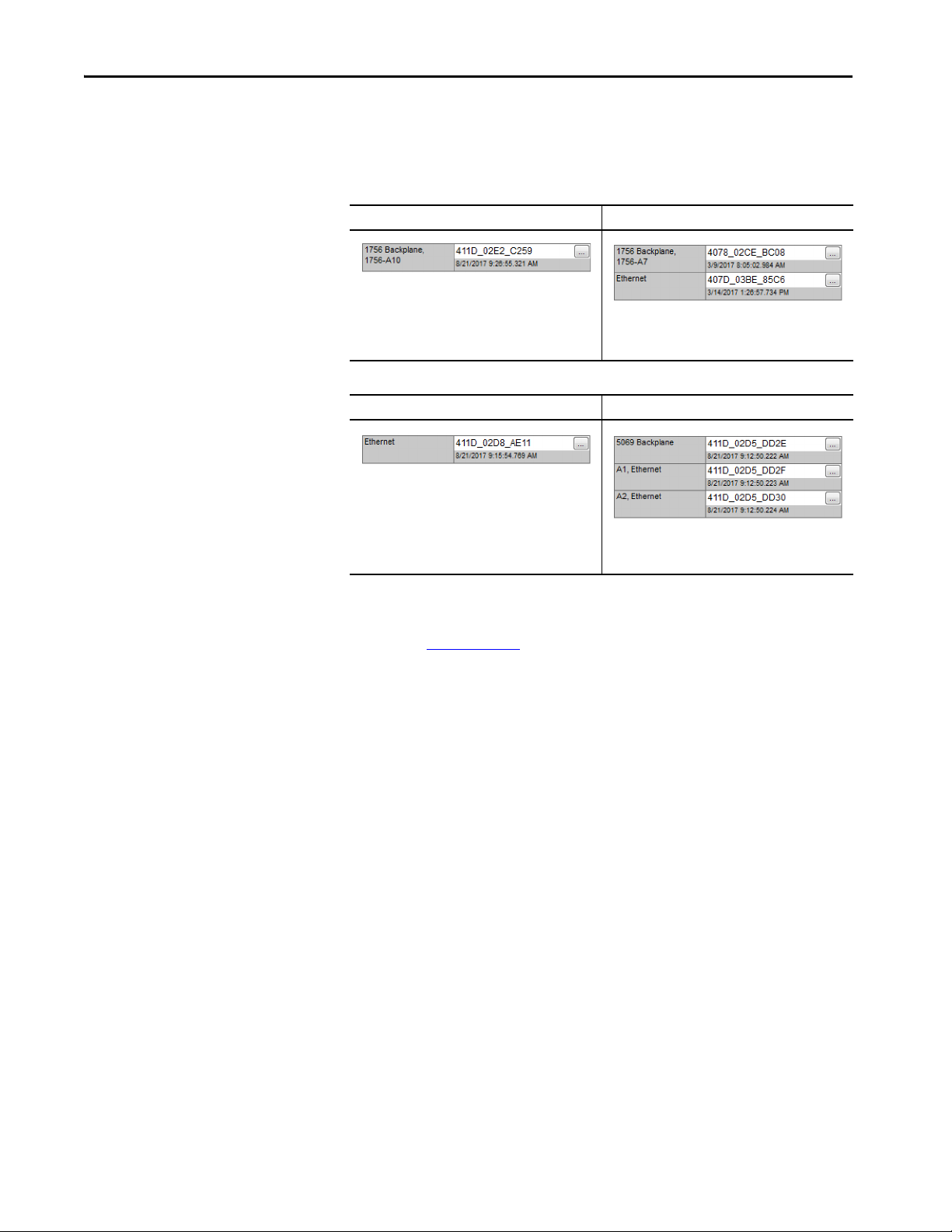
Chapter 4 Replacement Considerations with Safety Applications
Safety Network Number
The safety network number (SNN) uniquely identifies CIP Safety™ subnets
within a routable safety network. The combination of the SNN + Node
Address uniquely identifies each CIP Safety port on each device in the routable
safety network.
GuardLogix 5570 GuardLogix 5580
GuardLogix 5570 controllers have one SNN for the
backplane communications.
Compact GuardLogix 5370 Compact GuardLogix 5380
Compact GuardLogix 5370 controllers have one SNN for
the embedded Ethernet ports.
The GuardLogix 5580 requires two SNNs, one for the
embedded Ethernet port, and one for the backplane
communications
The Compact GuardLogix 5380 controllers have a SNN
for each embedded Ethernet port, and one for the
backplane communications
For an explanation of the Safety Network Number, see the GuardLogix 5580
and Compact GuardLogix 5380 Controller Systems Safety Reference Manual,
publication 1756-RM012.
86 Rockwell Automation Publication 1756-RM100F-EN-P - October 2018

Replacement Considerations with Safety Applications Chapter 4
Produce/Consume Safety Tags
GuardLogix 5580 and Compact GuardLogix 5380 controllers can produce
standard tags as unicast or multicast, but they can only produce safety tags as
unicast. The controllers can consume safety tags as either unicast or multicast.
When you configure a produced safety tag, you are only allowed to configure
unicast connection options. Logix Designer does not allow you to configure
multicast connection options.
When you configure a consumed tag, you must consider the capabilities of the
producer:
• If the producer in the I/O tree of this controller is a GuardLogix 5580 or
Compact GuardLogix 5380 controller, and you are consuming a safety
tag, you must configure the consumed tag to use unicast.
• If the producer in the I/O tree of this controller is a GuardLogix 5570 or
5560 controller, or a Compact GuardLogix 5370 controller, the safety
consumed tag can be configured as either unicast or multicast.
• Produce/Consume from GuardLogix 5570 (V28) to GuardLogix 5570
(V28) in local chassis; and change the Producer to GuardLogix 5580
(SIL2 or SIL3)
• The GuardLogix 5580 can only produce safety tags using Unicast
connections. An older safety controller (such as GuardLogix 5570) in
the same chassis as the GuardLogix 5580 will not be able to consume
safety tags, because backplane consumed tags cannot be configured as
Unic as t.
• For multi-controller Produce/Consume safety systems in the same
chassis, you must upgrade all the safety controllers to Studio 5000 Logix
Designer® version 31 or later. This works because V31 allows the
backplane safety consumed tags to be configured as Unicast.
The fault code for these unicast/multicast issues is
Code 0124 / Connection Request error / Invalid input network
connection type.
Rockwell Automation Publication 1756-RM100F-EN-P - October 2018 87

Chapter 4 Replacement Considerations with Safety Applications
Safety Application Conversion
When you import a Logix Designer project that was created in an earlier
version of Logix Designer application, the project is converted to the later
version.
IMPORTANT The standard side of Compact GuardLogix 5380 and GuardLogix 5580
Controllers operate the same as standard CompactLogix™ 5380 and
ControlLogix® 5580 controllers.
The other chapters in this publication cover the standard side of the
controllers. Before you convert your safety application, make sure you read
and understand the rest of the chapters in this publication.
Compact GuardLogix 5380 Controllers
• During import from Compact GuardLogix 5370 to Compact
GuardLogix 5370 version 31 application; the application remains a
SIL3 project.
• When you change the controller from Compact GuardLogix 5370 to
Compact GuardLogix 5380, 1769 modules will be deleted, since 1769
modules no longer communicate to Compact GuardLogix 5380
controllers.
• The project also changes from a SIL3 (only SIL3 possible in Compact
GuardLogix 5370) project in 5370 to a SIL2/PLd project in 5380 (only
SIL2 possible in Compact GuardLogix 5380 at this time).
• The safety signature is deleted during the application conversion.
GuardLogix 5580 Controllers
• During import from GuardLogix 5570 (V20 to V30) to GuardLogix
5570 V31, it remains a SIL3 project. The safety controller and safety
partner remain in the same two slots.
• When you change the controller from GuardLogix 5570 to GuardLogix
5580, it remains a SIL3 project. To change the GuardLogix 5580 from a
SIL3 to SIL2 project, just change the safety level in the safety tab. The
application then deletes the safety partner.
• The safety signature is deleted during the application conversion.
Exporting and importing Safety Add-on Instructions
To help optimize the internal memory structures:
• Import the version 30 or earlier project from an ASCII.L5K or an XML
.L5X file to create the version 31 or later project.
• Import rungs, routines, programs, equipment phases, UDTs, tags, and
Add-On Instructions into a version 31 or later project.
For more information on how to import your project, see:
• Logix 5000™ Controllers Import/Export Reference Manual, publication
1756-RM084.
• Logix 5000 Controllers Import/Export Project Components
Programming Manual, publication 1756-PM019.
88 Rockwell Automation Publication 1756-RM100F-EN-P - October 2018
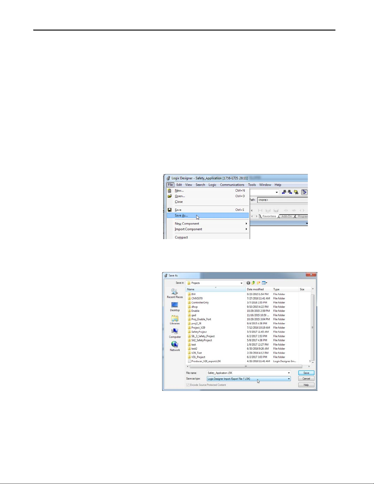
Replacement Considerations with Safety Applications Chapter 4
Convert a Safety Application
To convert from a Compact GuardLogix 5370 or GuardLogix 5570 controller
to a Compact GuardLogix 5380 or GuardLogix 5580 controller, follow this
procedure:
TIP The example in this procedure converts a 1756-L72S controller to a
1756-L84ES controller.
1. Export the project to an ASCII .L5K or XML .L5X file.
In a pre-version 31 Release, export the project to an ASCII .L5K or
XML .L5X file. You can only export a project if you have the project file
open.
a. From the File menu, choose Save As.
b. In the File name field, enter a name for the export file. You do not
need to add a file extension, but if you do, you must use the .L5K
extension.
c. Choose Logix Designer Import/Export File (*.L5K, .L5X) from the
Save As Type field. Note that you can skip this step if you entered the
extension (.L5K or .L5X) in step b.
d. Click Save to export the project file.
Rockwell Automation Publication 1756-RM100F-EN-P - October 2018 89

Chapter 4 Replacement Considerations with Safety Applications
IMPORTANT • If you are offline, and there are one or more properties dialog boxes with
2. Import the project from an ASCII .L5K or an XML .L5X file into
pending edits, the edits are automatically applied.
• If you are online, you are prompted to apply the edits.
• If you are online, you are prompted to upload tag values from the
controller before exporting. This allows you to decide whether you want
the current tag values exported.
• If Force Masks are set in your project, they are exported. Upon import,
any Force Masks are input to the project, and the Online Bar indicator is
set to Forces Installed.
• The state of the Online Bar Forces Enabled indicator is not exported;
upon import, it is set to Forces Disabled. We do not recommend editing
force values in the export file.
Studio 5000 Logix Designer version 31.00.00 or later.
a. Launch the Studio 5000 Logix Designer application version 31.00.00
or later.
b. Choose Create > From Import.
c. Select the project file you want to open.
d. Click Open.
90 Rockwell Automation Publication 1756-RM100F-EN-P - October 2018
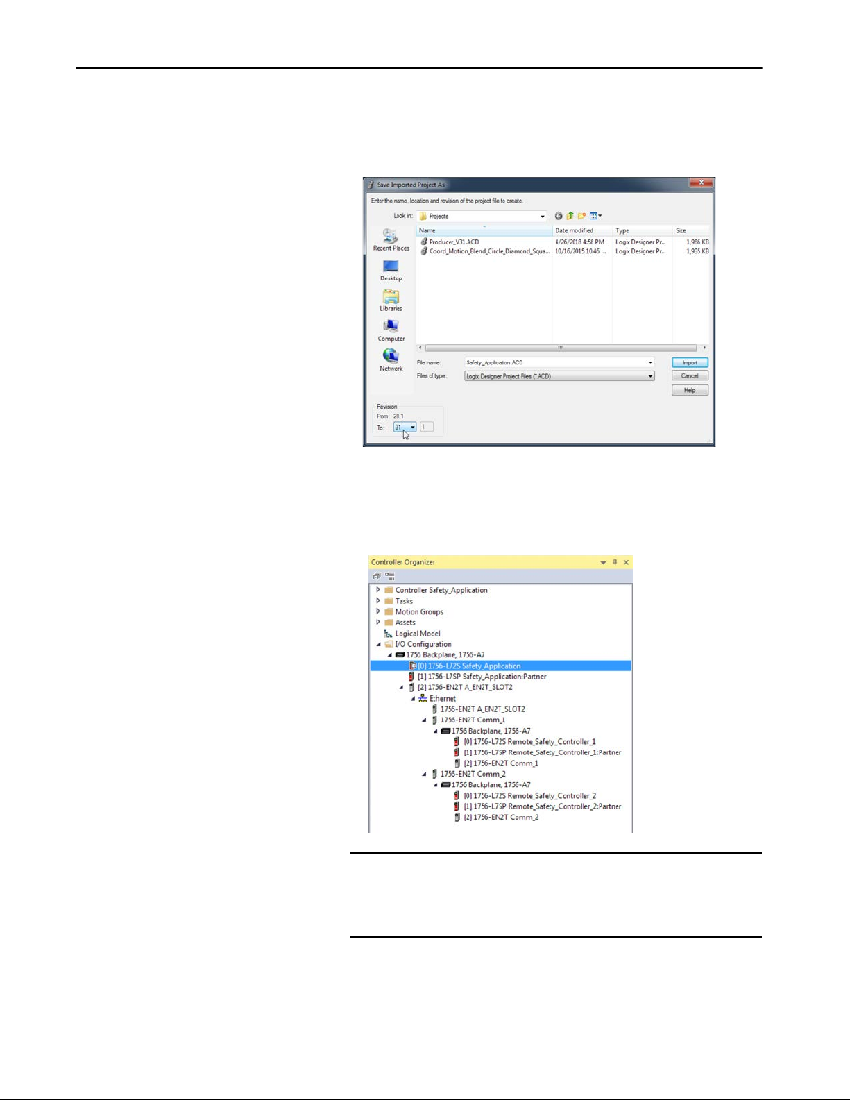
Replacement Considerations with Safety Applications Chapter 4
e. The Save Imported Project As dialog opens.
The import process must create a project file - you must specify the
name, location and revision of the project file to create.
f. Click Import to open the project file.
Once the project file is opened, the Controller Organizer appears,
and shows everything in the controller as of the time when the
project file was last saved.
IMPORTANT If you import an .L5K or .L5X file that contains Serial Port, DF1, or
ASCII elements into a project that uses a controller with no serial
ports results in an import error. The import then continues to
completion.
Rockwell Automation Publication 1756-RM100F-EN-P - October 2018 91

Chapter 4 Replacement Considerations with Safety Applications
3. Change the GuardLogix 5570/Compact GuardLogix 5570 controller to
IMPORTANT • If you change from a GuardLogix 5570 safety controller with a SIL 3/PLe
a GuardLogix 5580/Compact GuardLogix 5580 controller.
application to a Compact GuardLogix 5380 controller, the application
changes to SIL 2/PLd.
• If you change from a GuardLogix 5570 safety controller with a SIL 3/PLe
application to a GuardLogix 5580 controller, it defaults to a SIL 3/PLe
configuration. The safety controller and safety partner remain in the
same two slots in the I/O tree. If you want to change the GuardLogix
5580 from a SIL 3/PLe to SIL 2/PLd safety project, then change the safety
level in the Safety tab on the Controller Properties dialog box.
a. Open the Controller Properties, and click Change Controller.
b. Select your safety controller in the Change Controller dialog box,
and click OK.
92 Rockwell Automation Publication 1756-RM100F-EN-P - October 2018

Replacement Considerations with Safety Applications Chapter 4
c. On the confirmation dialog, read the and be aware of the warning
messages.
d. On the confirmation dialog, click Yes.
e. Verify Errors and Warnings.
f. The 1756-L84ES safety controller retains the SIL 3/PLe
configuration.
Rockwell Automation Publication 1756-RM100F-EN-P - October 2018 93

Chapter 4 Replacement Considerations with Safety Applications
Replace Producer Controller
If the producer controller has changed to a GuardLogix 5580 SIL 2 application
(1-slot solution without a safety partner), while the consumer controller is a
GuardLogix 5570 or earlier, the consumer controller can fault due to the
missing safety partner in the producer.
The data appears properly, but there is a yellow yield sign (signifying a fault)
next to the partner because the partner does not exist. Since there are no singleslot safety controllers available in the Studio 5000 Logix Designer application
version 28, you cannot resolve the issue by selecting another controller to
represent the single-slot GuardLogix 5580 controller in the SIL 2 application.
Here is the fault for the non-existent partner:
To help eliminate faults:
• In the version 31 producer project, do not place any hardware in the slot
to the right of the GuardLogix 5580 SIL 2 controller.
• In the consumer version 28 project, send an SSV to the 1756-L7SP to
programmatically inhibit the partner module. Place the SSV in the
standard routine. The '4' represents bit 2 of the attribute. To un-inhibit
the module, set bit 2 back to 0. The partner cannot be inhibited from
the I/O tree. The SSV is needed to inhibit the partner only.
If only standard tags are being produced by the GuardLogix 5580 SIL2
controller, then the existing GuardLogix 5570 controller in the consumer
project can be replaced by a ControlLogix 5570 controller. Since the
GuardLogix 5570 version 28 controller is consuming standard tags, there is no
need for the device in the I/O tree to be a [2-slot] safety controller. Replacing it
with any single-slot controller can help eliminate the connection fault.
94 Rockwell Automation Publication 1756-RM100F-EN-P - October 2018

Chapter 5
Standard Application Conversion
Top ic Pag e
Converting Logix Designer Projects 95
Produce and Consume Tags 96
Late Binding of I/O Data 103
I/O Data Manipulation 104
Motion Applications 105
Pending Edits 107
This chapter describes application conversions for the controllers. This chapter
features these controllers, and where applicable, the controllers are known as:
Controller Family Includes these controllers
5580 controllers ControlLogix® 5580 and GuardLogix® 5580 controllers
5380 controllers CompactLogix™ 5380 and Compact GuardLogix 5380 controllers
5570 controllers ControlLogix 5570 and GuardLogix 5570 controllers
5370 controllers CompactLogix 5370 and Compact GuardLogix 5370 controllers
Converting Logix Designer Projects
When you open a Studio 5000 Logix Designer® project to open a project that
was created in an earlier version of Logix Designer application, the project is
converted to the higher version. After the conversion, the Logix Designer
application can fail to use internal memory structures in the most efficient
manner.
To help optimize the internal memory structures, you can complete
the following:
• Import the version 27 or earlier project from an ASCII.L5K or an XML
.L5K file to create the version 28 or later project.
• Import rungs, routines, programs, equipment phases, UDTs, tags, and
Add-On Instructions into a version 28 or later project.
For information on how to import your project, see:
• Logix 5000™ Controllers Import/Export Reference Manual, publication
1756-RM084
.
• Logix 5000 Controllers Import/Export Project Components
Programming Manual, publication 1756-PM019
.
Rockwell Automation Publication 1756-RM100F-EN-P - October 2018 95

Chapter 5 Standard Application Conversion
Produce and Consume Tags
The recommendations in this section provide techniques for establishing
produced or consumed tag communication between the following:
• 5580 and 5570 controllers
• 5380 and 5370 controllers
RPI of Multicast Tags
In version 27 or earlier projects, a produced tag produces data at the RPI of the
fastest requesting consumer. This let multiple consumers with different RPIs
successfully connect to a producer.
In version 28 or later projects, the first consumer of a produce tag determines
the RPI rate at which data is produced. All subsequent consumers must request
the same RPI value as the first consumer. Otherwise, the subsequent consumers
fail to connect.
When you migrate a Logix Designer project, version 27 or earlier, to a later
version of the application, verify that the multicast consumers of a produce tag
are configured properly in the original project. Ta b l e 1 4
information.
Table 14 - Proper Configuration of Multicast Consumers of a Produced Tag
provides more
Consuming Controller Producing Controller Description
Any controller, version 17
or earlier
Any controller, version 18
or later
Any controller, version 20
or later
ControlLogix 5580 controller,
version 28 or later
CompactLogix 5380
controller, version 28 or later
Verify that all multicast consumed tags of a
produced tag are configured with the same RPI. If
they are not, some of the consumers can fail to
connect.
Verify that one of the following exists:
• All multicast consumers of a produced tag are
configured with the same RPI.
• All consumers are configured to Allow
Consumed Tags To Use RPI Provided By
Producer.
Verify that one of the following exists:
• All multicast consumers of a produced tag are
configured with the same RPI.
• All consumers are configured to Allow
Consumed Tags To Use RPI Provided By
Producer.
96 Rockwell Automation Publication 1756-RM100F-EN-P - October 2018

Standard Application Conversion Chapter 5
Data Structures
The Logix Designer application has requirements for data type use. The
requirements differ based on the Logix Designer application version that
you use.
Logix Designer Application Version Requirement
Version 26 or earlier Logix 5000 controllers require all data types to be placed on 4-byte
Version 27 or later Logix 5000 controllers require 8-byte (64-bit) data types (LINTs) to be
The Logix Designer application manages the requirement automatically, and
the change has no effect on individual LINT tags, regardless of
application version.
The requirement change between Logix Designer application, version 26, and
version 27 is fundamental to the application and applies to all Logix 5000
controllers. The fact that the requirement was changed does not alone require
action on your part.
address boundaries in RAM.
placed on 8-byte address boundaries in RAM.
Conditions can exist within which the change between Logix Designer
application, versions 26, and version 27 contributes to the need for action on
your part.
If you migrate a Logix Designer project, version 26 or earlier, to a Logix
Designer project, version 27 or later, LINTs inside a UDT can be misaligned.
Additional pad bytes are added to the data structure to account for the
misalignment. The pad bytes can cause an increase in the size of the UDT.
The possible effects of data structure changes, and subsequent actions that you
can take as a result, are described in the rest of this section.
IMPORTANT You must act when in the following conditions:
• You migrate a project, version 26 or earlier, to project, version 27 or later,
and you have LINT tags inside a UDT.
• Your application includes Logix 5000 controllers, version 26 or earlier,
that communicate with Logix 5000 controllers, version 27 or later.
Rockwell Automation Publication 1756-RM100F-EN-P - October 2018 97

Chapter 5 Standard Application Conversion
Possible Impact of Requirement Change
You can adapt your project to accommodate larger structure sizes, if necessary.
You can see the following effects due to the larger size:
• Message instruction data lengths can require changes to
complete successfully.
• Copy lengths of data structures can change.
• Produce/Consume connections to other Logix controller types can have
data type mismatches and require changes to complete successfully.
To correct Produce/Consume errors that are caused by UDT alignment
changes, modify the tag structures in both projects so that they match.
• Produce/Consume with Status requires an exact match of the UDT
definition (including the name of the UDT definition).
• Produce/Consume without Status requires the Size of the UDT to
match.
We recommend that you copy and paste the UDT definition from one project
to the other to cover both of these cases. Use the Data Type editor to check the
Data Type Size in both projects:
Figure 16 - Data Type Editor
98 Rockwell Automation Publication 1756-RM100F-EN-P - October 2018

Standard Application Conversion Chapter 5
If the data type size is different between the two projects, modify the UDT to
produce the same internal data structure.
The following sample UDT illustrates how the 8-byte allocation rule and the
8-byte alignment rule cause a UDT to have another size.
Figure 17 - UDT Sample - Needs Additional Memory Allocation and Alignment
Ta b l e 1 5 illustrates how this data structure maps in a Logix Designer project,
version 26 or earlier. MyLint is split across two 64-bit words, and the total size
is only 32 bytes.
Table 15 - Data Structure for Logix Designer Projects, Version 26 or Earlier
Word Elements Byte Mapping Table 64 Bit Boundaries
0 LimitA and LimitB Pad Pa d Pad Hidden
SINT
1 Profile (Real [3]) Map Map Map Map
2 Map Map Map Map 1
3 Map Map Map Map
4 Interlock (Int) Pad Pad Map Map 2
5 MyLint (LINT) Map Map Map Map
6
7 Speed (REAL) Map Map Map Map
Map Map Map Map 3
0
Rockwell Automation Publication 1756-RM100F-EN-P - October 2018 99
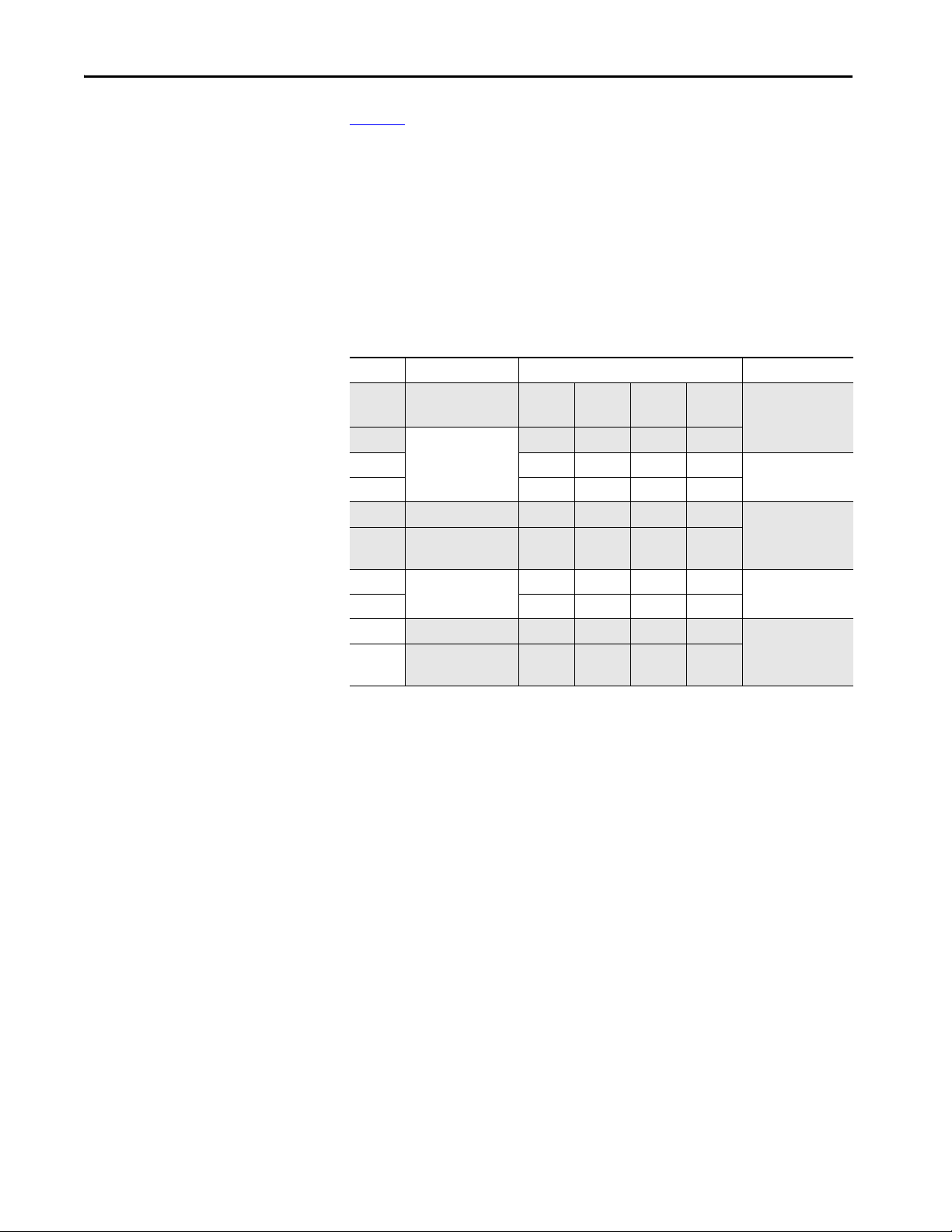
Chapter 5 Standard Application Conversion
Ta b l e 1 6 illustrates the hidden padding bytes that the Logix Designer
application automatically adds to achieve the 8-byte alignment and allocation
rules for a Logix Designer project, version 27 or later.
Consider the following:
• Padding is added in Word 5 so that MyLint starts at an 8-byte boundary.
• Padding is added in Word 9 so that the entire structure is a multiple of
8bytes.
Table 16 - Hidden Padding Added for Logix Designer Projects, Version 27 or Later
Word Elements Byte Mapping Table 64 Bit Boundaries
0 LimitA and LimitB Pa d Pad Pa d Hidden
SINT
1 Profile (Real [3]) Map Map Map Map
2 Map Map Map Map 1
3 Map Map Map Map
4 Interlock (Int) Pa d Pad Map Map 2
5 Padding for 8-byte
alignment
6 MyLint (LINT) Map Map Map Map 3
7 Map Map Map Map
8
9 Padding for 8-byte
Speed (REAL) Map Map Map Ma p 4
allocation
Pad Pa d Pad Pa d
Pad Pa d Pad Pa d
0
100 Rockwell Automation Publication 1756-RM100F-EN-P - October 2018
 Loading...