

Page 1
Installation Instructions
Original Instructions
Compact I/O Expansion Power Supplies
Catalog Numbers
1769-PA2,1769-PA2K, 1769-PB2,1769-PB2K, 1769-PA4,1769-PA4K,
1769-PB4,1769-PB4K
Topic Page
Summary of Changes 2
Before You Begin 5
Assemble the System 8
Mount an I/O Expansion Power Supply 10
Verify Your System Power 13
Power Considerations 14
Use a Master Control Relay 16
Schematic (Using IEC Symbols) 17
Schematic (Using ANSI/CSA Symbols) 18
Connect the Power Supplies 18
Connect Field Wires 20
Replace the Fuse 23
Temperature Derating 24
Power Dissipation 27
Specifications 29
Additional Resources 33
Compact I/O™ power supplies provide 120/240V AC and 24V DC power to modules, which
you can place to the left or the right side of the 1769 power supply. As many as eight I/O
modules can be placed on each side of the power supply.
Page 2
Compact I/O Expansion Power Supplies
Summary of Changes
This publication contains new and updated information as indicated in this table.
Topi c Page
Updated document with current specifications and certifications Throughout
Updated document with new catalog numbers: 1769-PA2K, 1769-PB2K, 1769-PA4K, 1769-PB4K Throughout
North American Hazardous Location Approval
The following information applies when operating
this equipment in hazardous locations.
Produ cts mar ked "CL I , DIV 2, GP A, B, C, D" are su itable for use
in Class I Division 2 Groups A, B, C, D, Hazardous Locations and
nonhazardous locations only. Each product is supplied with
markings on the rating nameplate indicating the hazardous
location temperature code. When combining products within
a system, the most adverse temperature code (lowest "T"
number) may be used to help determine the overall
temperature code of the system. Combinations of equipment
in your system are subject to investigation by the local
Authority Having Jurisdiction at the time of installation.
WARNIN G:
Explosion Hazard –
• Do not disconnect equipment unless
power has been removed or the area
is known to be nonhazardous.
• Do not disconnect connections to this
equipment unless power has been
removed or the area is known to be
nonhazardous. Secure any external
connections that mate to this
equipment by using screws, sliding
latches, threaded connectors, or other
means provided with this product.
• Substitution of components may
impair suitability for Class I, Division
2.
• If this product contains batteries, they
must only be changed in an area
known to be nonhazardous.
Informations sur l’utilisation de cet équipement en
environnements dangereux.
Les produits marqués "CL I, DIV 2, GP A, B, C, D" ne conviennent
qu'à une utilisation en environnements de Classe I Division 2
Groupes A, B, C, D dangereux et non dangereux. Chaque produit
est livré avec des marquages sur sa plaque d'identification qui
indiquent le code de température pour les environnements
dangereux. Lorsque plusieurs produits sont combinés dans un
système, le code de température le plus défavorable (code de
température le plus faible) peut être utilisé pour déterminer le
code de température global du système. Les combinaisons
d'équipements dans le système sont sujettes à inspection par l es
autorités locales qualifiées au moment de l' installation.
AVERTISSEMENT:
Risque d’Explosion –
• Couper le courant ou s'assurer que
l'environnement est classé non
dangereux avant de débrancher
l'équipement.
• Couper le courant ou s'assurer que
l'environnement est classé non
dangereux avant de débrancher les
connecteurs. Fixer tous les connecteurs
externes reliés à cet équipement à l'aide
de vis, loquets coulissants, connecteurs
filetés ou autres moyens fournis avec ce
produit.
• La substitution de composants peut
rendre ce t équipemen t inadapté à u ne
utilisation en environnement de Classe I,
Division 2.
• S'assurer que l'environnement est classé
non dangereux avant de changer les
piles.
2 Rockwell Automation Publication 1769-IN028I-EN-P - July 2020
Page 3
Environment and Enclosure
ATTENTION: This equipment is intended for use in a Pollution Degree 2 industrial environment, in
overvoltage Category II applications (as defined in EN/IEC 60664-1), at altitudes up to 2000 m
(6562 ft) without derating.
This equipment is not intended for use in residential environments and may not provide adequate
protection to radio communication services in such environments.
This equipment is supplied as open-type equipment for indoor use. It must be mounted within an
enclosure that is suitably designed for those specific environmental conditions that will be
present and appropriately designed to prevent personal injury resulting from accessibility to live
parts. The enclosure must have suitable flame-retardant properties to prevent or minimize the
spread of flame, complying with a flame spread rating of 5VA or be approved for the application if
nonmetallic. The interior of the enclosure must be accessible only by the use of a tool. Subsequent
sections of this publication may contain more information regarding specific enclosure type
ratings that are required to comply with certain product safety certifications.
In addition to this publication, see the following:
• Industrial Automation Wiring and Grounding Guidelines, publication 1770-4.1
installation requirements.
• NEMA Standard 250 and EN/IEC 60529, as applicable, for explanations of the degrees of
protection provided by enclosures.
Prevent Electrostatic Discharge
Compact I/O Expansion Power Supplies
, for more
ATTENTION: This equipment is sensitive to electrostatic discharge, which can cause internal
damage and affect normal operation. Follow these guidelines when you handle this equipment:
• Touch a grounded object to discharge potential static.
• Wear an approved grounding wriststrap.
• Do not touch connectors or pins on component boards.
• Do not touch circuit components inside the equipment.
• Use a static-safe workstation, if available.
• Store the equipment in appropriate static-safe packaging when not in use.
WARNING: EXPLOSION HAZARD
Do not connect or disconnect connectors while circuit is live.
Waste Electrical and Electronic Equipment (WEEE)
At the end of its life, this equipment should be collected separately from any unsorted municipal waste.
Rockwell Automation Publication 1769-IN028I-EN-P - July 2020 3
Page 4
Compact I/O Expansion Power Supplies
Always hard-wire circuits that are installed on the machine for safety reasons directly to the
master control relay. Examples include overtravel limit switches, stop push buttons, and
interlocks. These devices must be wired in series so that when any one device opens, the master
control relay is de-energized, which removes power from the machine.
ATT EN TI ON : Never alter these circuits to defeat their function. Serious injury or machine damage
could result.
Hazardous Location Approval
Only 1769-PB2, 1768-PB2K, 1769-PB4, and 1769-PB4K power supplies.
European Hazardous Location Approval
The following applies to products marked , II 3 G. Such modules:
• Are Equipment Group II, Equipment Category 3, and comply with the Essential Health and Safety Requirements relating to the
design and construction of such equipment given in Annex II to Directive 2014/34/EU. See the EC Declaration of Conformity at
http://www.rockwellautomation.com/products/certification
• The type of protection used is ‘Ex nA IIC T4 Gc’ according to EN 60079-15.
• Comply to Standards EN 60079-0:2012+A11:2013, EN 60079-15:2010, reference certificate number DEMKO 18 ATEX 2140X.
• Modules are intended for use in areas in which explosive atmospheres caused by gases, vapors, mists, or air or dust mixtures are
unlikely to occur, or are likely to occur only infrequently and for short periods. Such locations correspond to Zone 2 classification
according to ATEX directive 2014/34/EU.
for details.
IEC Hazardous Location Approval
The following applies to products with IECEx certification. Such modules:
• Are intended for use in areas in which explosive atmospheres caused by gases, vapors, mists, or air are unlikely to occur, or are
to occur only infrequently and for short periods. Such locations correspond to Zone 2 classification to IEC 60079-0.
likely
• The type of protection is ‘Ex nA IIC T4 Gc’ according to IEC 60079-15.
•
Comply to Standards: IEC 60079-0:6th edition, IEC-60079-15:4th Edition, reference IECEx certificate number IECEx UL 20.0078X.
4 Rockwell Automation Publication 1769-IN028I-EN-P - July 2020
Page 5
Compact I/O Expansion Power Supplies
WARNING: Special Conditions for Safe Use:
• This equipment is not resistant to sunlight or other sources of UV radiation.
• This equipment shall be mounted in an ATEX/IECEx Zone 2 certified enclosure with a minimum
ingress protection rating of at least IP54 (as defined in EN/IEC 60529) and used in an
environment of not more than Pollution Degree 2 (as defined in EN/IEC 60664-1) when applied
in Zone 2 environments. The enclosure must be accessible only by the use of a tool.
• This equipment shall be used within its specified ratings defined by Rockwell Automation.
• Provision shall be made to prevent the rated voltage from being exceeded by transient
disturbances of more than 140% of the rated voltage when applied in Zone 2 environments.
• This equipment must be used only with ATEX/IECEx certified Rockwell Automation backplanes.
• Do not disconnect equipment unless power has been removed or the area is known to be
nonhazardous.
• Secure any external connections that mate to this equipment by using screws, sliding latches,
threaded connectors, or other means provided with this product.
ATT EN TI ON : This equipment is not resistant to sunlight or other sources of UV radiation.
Before You Begin
There are some points about power distribution that you must know.
• The master control relay must be able to inhibit all machine motion by removing power
to the machine I/O devices when the relay is de-energized. We recommend that the
controller remains powered even when the master control relay is de-energized.
• If you are using a DC power supply, interrupt the load side rather than the AC line
power. This operation avoids the additional delay of power supply turn-off. The DC
power supply must be powered directly from the fused secondary of the transformer.
Power to the DC input and output circuits must be connected through a set of master
control relay contacts.
Perform Periodic Tests of Master Control Relay Circuit
Any part can fail, including the switches in a master control relay circuit. The failure of one of
these switches would most likely cause an open circuit, which would be a safe power-off failure.
However, if one of these switches shorts out, it no longer provides any safety protection. These
switches must be tested periodically to make sure they stop machine motion when needed.
Rockwell Automation Publication 1769-IN028I-EN-P - July 2020 5
Page 6
Compact I/O Expansion Power Supplies
1
2a
3
4
9
10
2b
1769-PA4
5b
6
5a
7a
7a
8a
8b
7b
7b
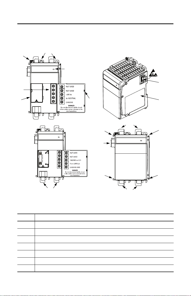
Parts Illustration of a Power Supply
The sample illustrations of a 1769-PA4 power supply let you review the various components that
comprise a power supply, which is attached to a DIN rail.
Power Supply Components
Item Description
1 Bus lever (with locking function)
2a Upper panel mounting tabs
2b Lower panel mounting tabs
3 Status Indicator
4 Power supply door with terminal identification label
5a Movable bus connector with female pins
5b Stationary bus connector with male pins
6 Rockwell Automation Publication 1769-IN028I-EN-P - July 2020
Page 7
Compact I/O Expansion Power Supplies
Power Supply Components (Continued)
Item Description
6 Nameplate label
7a Upper tongue-and-groove slots
7b Lower tongue-and- groove slots
8a Upper DIN rail latches
8b Lower DIN rail latches
9 Terminal block with fingersafe cover
10 Fuse housing cover for replaceable fuse
Install an I/O Expansion Power Supply
Compact I/O Expansion Power Supplies are suitable for use in an industrial environment when
installed in accordance with these instructions. Specifically, this equipment is intended for use in
(1)
clean, dry environments (Pollution degree 2
Category II
(2)
(IEC 60664-1).
(3)
) and to circuits that do not exceed Over Voltage
Disconnect the Power
WARNING: Remove power before removing or inserting this power supply from the 1769 I/O
system. When you remove or insert a power supply with power applied, an electrical arc may
occur. An electrical arc can cause personal injur y or property damage by:
• Sending an erroneous signal to your system’s field devices, causing unintended machine
motion.
• Causing an explosion in a hazardous environment.
Electrical arcing causes excessive wear to contacts on both the power supply and its mating
connector. Worn contacts may create electrical resistance.
(1) Pollution Degree 2 is an environment where, normally, only non-conductive pollution occurs except that occasionally a temporary conductivity that
is caused by condensation can be expec ted.
(2) Over Voltage Category II is the load level section of the electrical distribution system . At this level, transient voltages are controlled and do not
exceed the impulse voltage capability of the insulation of the p roduct.
(3) Pollution Degree 2 and Over Voltage Category II are International Electrotechnical Commission (IEC) designations.
Rockwell Automation Publication 1769-IN028I-EN-P - July 2020 7
Page 8
Compact I/O Expansion Power Supplies
2
1
1
3
4
5
6
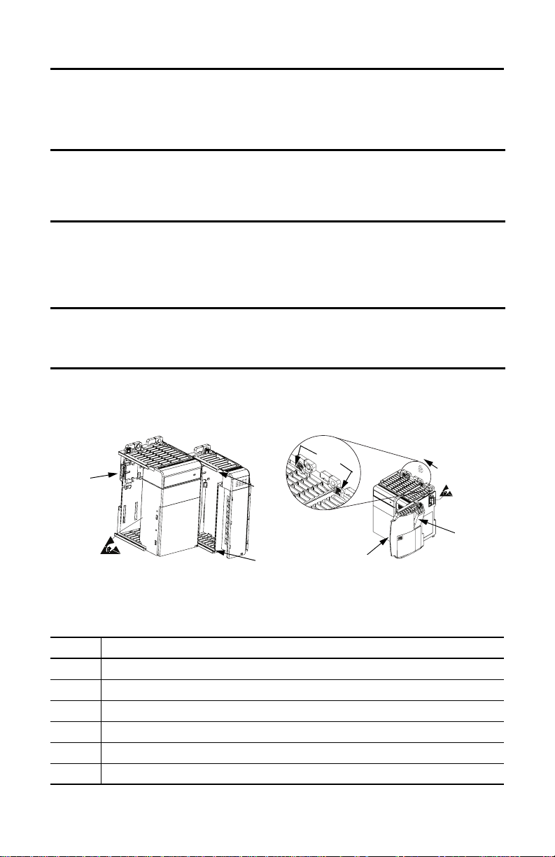
Assemble the System
1769 Compact I/O power supplies distribute power from either side of the power supply.
EXAMPLE A 2 amp at 5V DC power supply (1769-PA2, 1769-PA2K, 1769-PB2, 1769-PB2K) can provide
1 amp to the right side of the power supply and 1 amp to the left. A 4 amp at 5V DC power
supply (1769-PA4, 1769-PA4K, 1769-PB4, and 1769-PB4K) can provide 2 amps to the right
side of the power supply and 2 amps to the left.
The maximum amount of current the system supports in both directions is:
• 1769-PA2, 1769-PA2K, 1769-PB2, 1769-PB2K: 2 amps at 5V DC; 1 amp at 24V DC
• 1769-PA4, 1769-PA4K, 1769-PB4, 1769-PB4K: 4 amps at 5V DC; 2 amps at 24V DC
IMPORTANT The maximum amount of current that can be distributed from either side of any 1769 power
supply is 2 amps at 5V DC and 1 amp at 24V DC.
This condition is a limit of the 1769 Compact I/O Bus.
The power supply can be attached to an adjacent I/O module before or after
mounting.
Power Supply and Adjacent Module Components
Item Description
1 Upper and lower tongue-and-groove slots
2 Bus connectors
3 Positioning tab
4 Direction of the bus lever of the power supply to the I/O modules
5End cap terminator
6 End cap bus terminator
8 Rockwell Automation Publication 1769-IN028I-EN-P - July 2020
Page 9
Compact I/O Expansion Power Supplies
Follow these steps to assemble the Compact I/O system.
1. Disconnect your line power.
The power supply does not support removal or insertion of modules under power.
WARNING: If you connect or disconnect wiring while the field-side power is on, an electrical arc
can occur. This could cause an explosion in hazardous location installations. Be sure that power is
removed or the area is nonhazardous before proceeding.
2. Check that the bus lever of the power supply to be installed is in the unlocked (fully
right) position.
3. Use the upper and lower tongue-and-groove slots to secure the power supply to an I/O
module.
4. Move the power supply back along the tongue-and-groove slots until the bus connectors
align with each other.
5. Push the bus lever back slightly to clear the positioning tab.
Use your fingers or a small screwdriver.
6. To allow communication between the controller and the I/O, move the bus lever of the
power supply and its adjacent I/O modules fully to the left until it clicks.
Make sure it is locked firmly in place.
ATT EN TI ON : When attaching expansion I/O power supplies, it is very important that the bus
connectors are securely locked together to ensure proper electrical connection.
7. Attach an end cap terminator to the last I/O module in the system by using the tongueand-groove slots as before.
8. Lock the end cap bus terminator.
IMPORTANT A 1769-ECR or 1769-ECL right or left end cap (respectively) must be used to terminate the end
of the serial communication bus.
Rockwell Automation Publication 1769-IN028I-EN-P - July 2020 9
Page 10
Compact I/O Expansion Power Supplies
Power Supply
Compa ct I/O
Compa ct I/O
Compa ct I/O
Compa ct I/O
Top
Bottom
Side
Side
End Cap
End Cap
(1) (2)
50 mm
(2 in.)
50 mm
(2 in.)
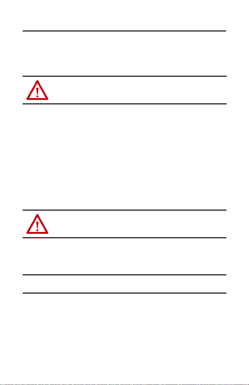
Mount an I/O Expansion Power Supply
ATT EN TI ON : During panel or DIN rail mounting of all devices, be sure that all debris (for example,
metal chips, wire strands) is kept from falling into the module. Debris that falls into the module
could cause damage on power up.
Minimum Spacing
Maintain spacing from enclosure walls, wireways, adjacent equipment, and so forth. Allow 50
mm (2 in.) of space on all sides for adequate ventilation.
Item Description
1 This device could be an end cap, controller, adapter, or expansion cable depending on your system configuration.
2 This device could be an end cap or expansion cable depending on your system configuration.
Prevent Excessive Heat
For most applications, normal convective cooling keeps the system within the specified operating
range. Verify that the specified temperature range is maintained. Proper spacing of components
within an enclosure is sufficient for heat dissipation.
In some applications, other equipment inside or outside the enclosure can produce a substantial
amount of heat. In this case, place blower fans inside the enclosure to help with air circulation
and to reduce hot spots near the system
Additional cooling provisions can be necessary when high ambient temperatures are
encountered.
TIP Do not bring in unfiltered outside air. Place the Compact I/O system in an enclosure to protect it from a
corrosive atmosphere. Harmful contaminants or dirt can cause improper operation or damage components.
In extreme cases, you can need to use air conditioning to protect against heat build-up within the enclosure.
10 Rockwell Automation Publication 1769-IN028I-EN-P - July 2020
Page 11
Compact I/O Expansion Power Supplies
Compa ct I/O
Compact I/O
End Cap
End Cap
Power Supply
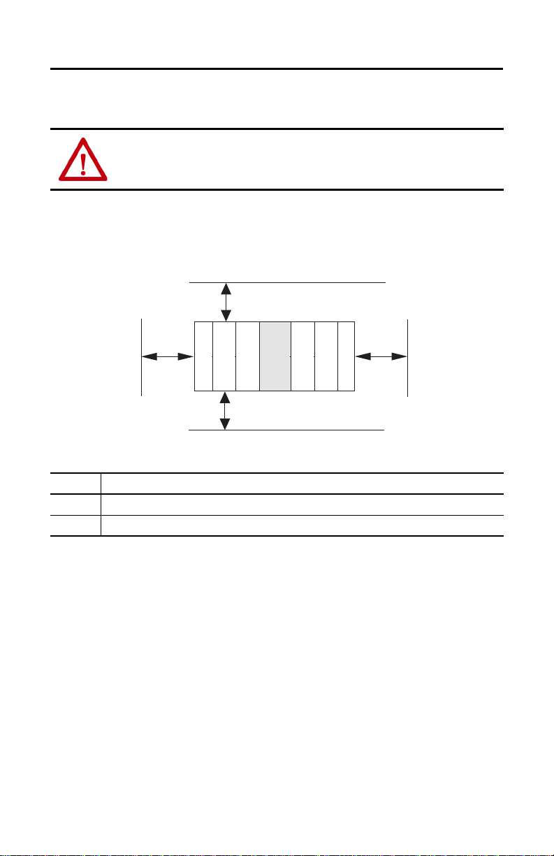
For more than 2 modules: (number of modules -1) X 35 mm (1.38 in.)
132
(5.197)
40
(1.58)
70
(2.76)
28.5
(1.12)
35
(1.58)
35
(1.58)
122.6 ±0.2
(4.826 ±0.008)
All dimensions are in mm (in.). Hole spacing tolerance: ±0.4 mm (0.016 in.)
Mount the Panel
Mount the power supply to a panel by using four screws per module. Use M4 or #8 panhead
screws. Mounting screws are required on each power supply panel mounting tab.
ATT EN TI ON : This product is intended to be mounted to a well-grounded mounting sur face such
as a metal panel. Additional grounding connec tions from the power supply's mounting tabs or DIN
rail (if used) are not required unless the mounting surface cannot be grounded. Refer to Industrial
Automation Wiring and Grounding Guidelines, Allen-Bradley publication 1770-4.1
information.
Panel Mounting Using the Dimensional Template
, for additional
Rockwell Automation Publication 1769-IN028I-EN-P - July 2020 11
Page 12

Compact I/O Expansion Power Supplies
1769 Cable
Mount a Power Supply on a DIN Rail
The power supply can be mounted using the following DIN rails:
• 35 x 7.5 mm (EN 50 022 - 35 x 7.5)
• 35 x 15 mm (EN 50 022 - 35 x 15)
1. Before mounting a power supply or module on a DIN rail, close the DIN rail latches.
2. Press the DIN rail mounting area of the module against the DIN rail.
The latches momentarily open and lock into place. The following illustration shows a
power supply being attached to the I/O modules in a DIN rail mounted Compact I/O
system.
12 Rockwell Automation Publication 1769-IN028I-EN-P - July 2020
Page 13

Compact I/O Expansion Power Supplies
Verify Your System Power
Your system power budget is a consideration when using 1769 power supplies. This budget
determines the power that is being provided to the I/O modules. See Power Supply Distance
Ratings in the CompactLogix™ System Selection Guide, publication 1769-SG001
requirements.
TIP The total number of I/O modules cannot exceed 16 on one bank with a maximum of 8 I/O
modules on either side of the power supply.
You system can be used in a maximum of two banks of I/O modules. This condition occurs
when you configure your system with a MicroLogix™ 1500 controller, one expansion cable,
one expansion power supply, and a total of eight I/O modules. The expansion power supply
cannot be directly connected to the MicroLogix 1500 controller.
1. After you have reviewed the amount of current consumed by your system, verify that
your power supply has adequate capacity for its bank of I/O modules.
See Tem pe ra tu re De ra ti n g
2. To do so, compare the current graphs to your totals for the following :
•Total 5V DC
• Total 24V DC
• Total 24V DC sensor power (1769-PA2, 1769-PA2K only)
3. If your power supply load is at or above the limits of the allowable ranges that are shown
in the graphs, you must add an additional I/O bank.
See Connect the Power Supplies
on page 24 for graphs.
on page 18 for additional information.
, for the power
IMPORTANT An additional I/O bank must include its own power supply.
An end cap/ terminator (1769-ECR or 1769-ECL) must al so be used if the I/O bank is the last in
the system.
Rockwell Automation Publication 1769-IN028I-EN-P - July 2020 13
Page 14

Compact I/O Expansion Power Supplies
Power Considerations
The following sections explain power considerations for the Compact I/O system.
Disconnect the Main Power
WARNING: EXPLOSION HAZARD
Do not replace components or disconnect equipment unless power has been switched off.
If you connect or disconnect wiring while the field-side power is on, an electrical arc can occur.
This could cause an explosion in haza rdous lo cation installations. Be sure that power is removed or
the area is nonhazardous before proceeding.
Install the main power disconnect switch where operators and maintenance personnel have
quick and easy access to it. Besides disconnecting electrical power, de-energize all other sources of
power (pneumatic and hydraulic) before you begin working on a machine or process that is
controlled by a controller.
Isolation Transformer Usage
You can use an isolation transformer in the AC line. This type of transformer provides isolation
from your power distribution system to reduce electrical noise and is often used as a step down
transformer to reduce line voltage. Any transformer that is used with the Compact I/O system
must have a sufficient power rating for its load. The power rating is expressed in volt-amperes
(VA). See Schematic (Using IEC Symbols)
transformers.
on page 17 for an example of circuits using isolation
Power Supply Inrush
During powerup, the power supply allows a brief inrush current to charge internal capacitors.
Many power lines and control transformers can supply inrush current for a brief time. If the
power source cannot supply this inrush current, the source voltage can sag momentarily.
The only effect of limited inrush current and voltage sag on the system is that the power supply
capacitors charge more slowly. However, the effect of a voltage sag on other equipment must be
considered. For example, a deep voltage sag can reset a computer that is connected to the same
power source. The following considerations determine whether the power source must be
required to supply high inrush current:
• Power-up sequence of devices in a system
• Amount of the power source voltage sag if the inrush current cannot be supplied
• Effect of voltage sag on other equipment in the system
If the entire system is powered up simultaneously, a brief sag in the power source voltage typically
does not affect any equipment.
14 Rockwell Automation Publication 1769-IN028I-EN-P - July 2020
Page 15

Compact I/O Expansion Power Supplies
Loss of Power Source
The power supply is designed to withstand brief power losses without affecting the operation of
the system. The time the system is operational during power loss is called “program scan hold-up
time after loss of power.” The duration of the power supply hold-up time depends on the type
and state of the I/O, but is typically between 5 milliseconds…10 seconds. When the duration of
power loss reaches this limit, the power supply signals the processor that it can no longer provide
adequate DC power to the system. This condition is referred to as a power supply shutdown.
The processor then performs an orderly shutdown of the controller.
Input States on Power Down
The power supply hold-up time is longer than the turn-on and turn-off times of the inputs.
Because of this, the processor can record the input state change from ‘On’ to ‘Off ’ that occurs
when power is removed before the power supply shuts down the system. Comprehension of this
concept is important. Write the program to compensate for this effect.
Other Types of Line Conditions
Occasionally the power source to the system can be temporarily interrupted. It is also possible
that the voltage level can drop substantially below the normal line voltage range for a time. Both
of these conditions are considered to be a loss of power for the system.
User Power Overcurrent Condition
The power supply shuts down if there is an overcurrent condition. All outputs latch off and
remain off until you remove the overcurrent and cycle power. Reload the user program following
a power supply shutdown.
ATT EN TI ON : To avoid unexpected operation due to 24V DC user power shutdown (1769-PA2 and
1769-PA2K only), monitor the 24V DC user output with a 24V DC input channel.
Rockwell Automation Publication 1769-IN028I-EN-P - July 2020 15
Page 16

Compact I/O Expansion Power Supplies
Use a Master Control Relay
A hard-wired master control relay (MCR) provides a reliable means for emergency machine
shutdown. Since the master control relay allows the placement of several emergency stop
switches in different locations, its installation is important from a safety standpoint. Overtravel
limit switches or mushroom-head push buttons are wired in series so that when any of them
opens, the master control relay is de-energized. This configuration removes power to input and
output device circuits.
ATT EN TI ON : Never alter these circuits to defeat their function since serious injury and/or machine
damage could result.
TIP If you are using an external DC power supply, interrupt the DC output side rather than the AC line side of the
supply. This process avoids the additional delay of power supply turn off.
Fuse the AC line of the DC output power supply.
Connect a set of master control relays in series with the DC power supplying the input and output circuits.
Place the main power disconnect switch where operators and maintenance personnel have quick
and easy access to it. If you mount a disconnect switch inside the enclosure, place the switch
operating handle on the outside of the enclosure, so that you can disconnect power without
opening the enclosure.
Whenever any of the emergency stop switches are opened, remove power to input and output
devices.
When you use the master control relay to remove power from the external I/O circuits, power
continues to be provided to the power supply of the system. This condition is so that you can still
observe the diagnostic indicators on the processor.
The master control relay is not a substitute for a disconnect to the system. It is intended for any
situation where the operator must quickly de-energize only I/O devices. When you inspect or
install terminal connections, replacing output fuses, or working on equipment within the
enclosure, use the disconnect to shut off power to the rest of the system.
TIP Do not c ontrol the ma ster control re lay with the Compact I/O system. Provide the operator with the safety of
a direct connection between an emergency stop switch and the master control relay.
16 Rockwell Automation Publication 1769-IN028I-EN-P - July 2020
Page 17

Schematic (Using IEC Symbols)
L1 L2
Disconnect
Isolation
Tran sfor mer
X1
X2
115V AC
or 230V
AC
Fuse
Operation of either of these contacts
removes power from the external
I/O circuits, which stops machine motion.
Emergency Stop Push
Button
Overtravel
Limit Switch
Stop
Start
Fuse
MCR
230V AC
I/O
Circuits
Master Control Relay (MCR)
Cat. No. 700-PK400A1
Suppressor
Cat. No. 700-N24
MCR
Suppr
MCR
MCR
115V AC or
230V AC
MCR
(Lo)
(Hi)
230V AC
24V DC
I/O Circuits
Line Terminals: Connect to the AC 1769
power supply terminals.
Line Terminals: Connect to the 24V DC 1769
power supply terminals.
DC Power Supply Use
EC950/ECN 60950
Compact I/O Expansion Power Supplies
Rockwell Automation Publication 1769-IN028I-EN-P - July 2020 17
Page 18

Compact I/O Expansion Power Supplies
L1 L2
Disconnect
Isolation
Tran sfor mer
X1
X2
Fuse
Operation of either of these contacts
removes power from t he external I/O
circuits, which stops machine motion.
Emergency-Sto p Push
Button
Overtravel Limit
Switch
Stop
Start
Fuse
MCR
230V AC
I/O
Circuits
Master Control Relay (MCR)
Cat. No. 700-PK400A1
Suppressor
Cat. No. 700-N24
MCR
Suppr
MCR
MCR
115V AC or
230V AC
DC Power Supply
-
+
24V DC I/O
Circuits
MCR
(Lo)
(Hi)
230V AC
Line Terminals: Connect to the 24V DC 1769
power supply terminals.
Line Terminals: Connect to the AC 1769
power supply terminals.
115V AC
or 230V
AC
Use NEC Cl ass 2 for
UL Listing
Schematic (Using ANSI/CSA Symbols)
Connect the Power Supplies
Compact I/O system architecture and the power supply design support connection of I/O on
either side of the power supply. Each I/O bank requires its own power supply.
To connect 2 I/O banks, attach a 1769 expansion I/O cable to a power supply or I/O module as
shown in the Power Supply Connection
illustration on page 19. Up to 8 I/O modules can be
connected on either side (A or B in the illustration) of the power supply for a maximum of 16
modules per bank.
Each 1769 I/O module has a power supply distance rating, with a maximum value of eight. See
the specific installation instructions for the specific 1769 I/O module for more information.
18 Rockwell Automation Publication 1769-IN028I-EN-P - July 2020
Page 19

Power Supply Connection
1
2
3
4
Bank 1
Bank 2
Compact I/O Expansion Power Supplies
Item Description
The maximum amount of bus current that can be distributed on the 1769 bus (on either side of the power supply, A
1, 2
3 Expansion I/O power supplies
4 I/O communication expansion cable
or B) is:
• 2 amps at 5V DC (assume supported by power supply)
• 1 amp at 24V DC (assume supported by power supply)
IMPORTANT To use a 1769 expansion I/O power supply with a controller that has an embedded power
supply (for example, MicroLogix 1500), you must use a 1769 expansion I/O cable. Do not
directly attach the expansion power supply to a controller that has an embedded power
supply.
Rockwell Automation Publication 1769-IN028I-EN-P - July 2020 19
Page 20

Compact I/O Expansion Power Supplies
Connect Field Wires
The following instructions explain how to wire your power supply.
Ground the Power Supply
ATT EN TI ON : This product is intended to be mounted to a well-grounded mounting sur face such
as a metal panel. Additional grounding connec tions from the power supply's mounting tabs or DIN
rail (if used) are not required unless the mounting surface cannot be grounded. Refer to Industrial
Automation Wiring and Grounding Guidelines, Allen-Bradley publication 1770-4.1
information.
Wire the Power Supply
Connect the ground screw of the power supply to the nearest ground or ground bus.
Use a 2.5 mm (14 AWG) wire and keep the leads as short as possible.
, for additional
ATT EN TI ON : This symbol denotes protective earth ground and earth ground terminals that
provide a low impedance path between electrical circuits and earth for safety purposes and
provides noise immunity improvements. You must make these connections for safety purposes.
20 Rockwell Automation Publication 1769-IN028I-EN-P - July 2020
Page 21

Compact I/O Expansion Power Supplies
Catalog Number 1769-PB2, 1769-PB2K
DC NEUTRAL
Catalog Number 1769-PA2, 1769-PA2K
+24V DC
CHASSIS GROUND
NOT USED
NOT USED
V AC COM (L2)
120/240V AC (L1)
CHASSIS GROUND
*PWR OUT COM
*PWR OUT +24V DC
Catalog Number 1769-PA4, 1769-PA4K
V AC COM (L2)
120/240V AC (L1)
CHASSIS GROUND
NOT USED
NOT USED
*24V DC user power for sensors or other special 24V DC I/O devices
Catalog Number 1769-PB4, 1769-PB4K
DC NEUTRAL
+24V DC
CHASSIS GROUND
NOT USED
NOT USED
1. Connect incoming power to the power supply terminals as indicated in this graphic.
ATT EN TI ON : Turn off incoming power before connecting or disconnecting wires. Failure to do so
could cause injury to personnel and/or damage to equipment.
Rockwell Automation Publication 1769-IN028I-EN-P - July 2020 21
Page 22

Compact I/O Expansion Power Supplies
Wirin g the
Fingersafe
Ter mi nal Bl ock
Wire the Fingersafe Terminal Block
When wiring the terminal block, keep the fingersafe cover in place.
1. Loosen the terminal screws to be wired.
2. Route the wire under the terminal pressure plate.
You can use the bare wire or a spade lug. The terminals accept a 6.35 mm (0.25 in.) spade
lug.
TIP The terminal screws are non-captive. Therefore, it is possible to use a ring lug [maximum
1/4-inch o.d. with a 0.139-inch minimum i.d. (M3.5)] with the module.
3. Tighten the terminal screw, making sure that the pressure plate secures the wire.
Recommended torque when you tighten terminal screws is 1.27 N•m (11.24 lb•in).
TIP If you must remove the fingersafe cover, insert a screwdriver into one of the square wiring
holes and gently pry the cover off. If you wire the terminal block with the fingersafe cover
removed, you cannot put it back on the terminal block because the wires are in the way.
Wire Size and Terminal Screw Torque
Each terminal accepts as many as two wires with the following restrictions.
Wire Type Wire Size Terminal Screw Torque
Solid Cu-90 °C (194 °F) 2.5 mm
22 Rockwell Automation Publication 1769-IN028I-EN-P - July 2020
2
(14 AWG) 1.27 N•m (11.24 lb•in)
Page 23

Compact I/O Expansion Power Supplies
NOT USED
NOT USED
+24V dc
dc NEUTRAL
CHASSIS
DANGER
Do not disconnect while circuit
is live unless area is known to be
non-hazardous
Tab
Fuse Housing Cover
Replace the Fuse
ATT EN TI ON : Never ins tall, remove, or wi re power supplies unless power has been switched off.
Follow these steps to replace a blown fuse.
1. Remove Compact I/O system power to correct conditions that are causing the short
circuit.
2. To remove the fuse housing cover, place a slotted screwdriver under the tab.
3. Use a fuse puller or similar device to remove the fuse.
Use care so that the printed circuit board and surrounding electronics are not damaged.
4. Replace the front access fuse by centering the replacement fuse over the fuse clip and
pressing down.
See Specifications
on page 29 for information on the front access fuse.
If you use a tool to press the fuse in place, apply pressure to only the metal end caps, not
to the center of the fuse.
5. Replace the fuse housing cover.
6. Restore Compact I/O system power.
Rockwell Automation Publication 1769-IN028I-EN-P - July 2020 23
Page 24

Compact I/O Expansion Power Supplies
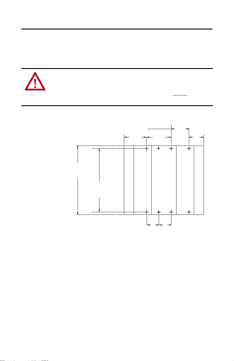
0.875
+5V Bus Load (Amps)
With User +24V Current Draw at 0 Amps
+24V Bus Load (Amps)
2.0
1.0
0.5
0.0
0.1 0.2 0.3 0.4 0.5 0.6 0.7 0.8 0.9 1.0
1.4
60 °C
55 °C
1.5
0.0
With User +24V Current Draw at 0.2 Amps
+24V Bus Load (Amps)
+5V Bus Load (Amps)
2.0
1.5
1.0
0.5
0.0
0.0 0.1 0.2 0.3 0.4 0.5 0.6 0.7 0.8 0.9 1.0
0.675 0.85
1.25
0.45
60 °C
55 °C
Temperature Derating
The following graphs indicate how much current can be drawn from the power supply at the
indicated case temperature without damaging it.
1769-PA2, 1769-PA2K Output Derating
24 Rockwell Automation Publication 1769-IN028I-EN-P - July 2020
Page 25
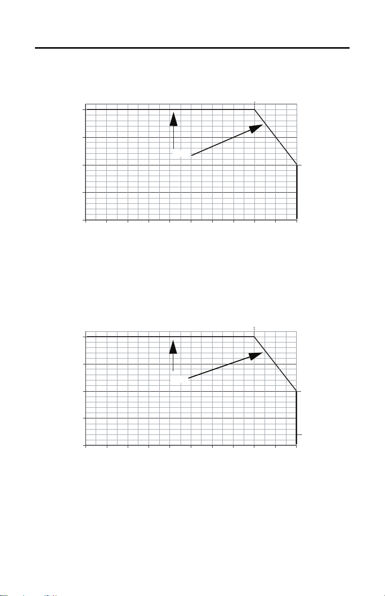
1769-PB2, 1769-PB2K Output Derating
With User +24V Current Draw at 0.25 Amps
+24V Bus Load (Amps)
+5V Bus Load (Amps)
0.0
0.1 0.2
0.3 0.4 0 .5
0.6 0.7
0.8 0.9
1.0
2.0
1.5
1.0
0.5
0.0
0.8
1.0
55 °C
+24V Bus Load (Amps)
+5V Bus Load (Amps)
0.0
0.1
0.2
0.3
0.4
0.5
0.6
0.7
0.8
0.9
1.0
2.0
1.5
1.0
0.5
0.0
0.8
1.0
0.2
60 °C
Total Output: 29 W at 60 °C (140 °F) or below
Compact I/O Expansion Power Supplies
Rockwell Automation Publication 1769-IN028I-EN-P - July 2020 25
Page 26

Compact I/O Expansion Power Supplies
+24V Bus Load (Amps)
+5V Bus Load (Amps)
4.0
3.0
2.0
1.0
0.0
0.0 0.2 0.4 0.6 0.8 1.0 1.2 1.4 1.6 1.8 2.0
1.7
2.6
55 °C
60 °C
Total Output: 68 W at 55 °C (131 °F) or below
61 W at 60 °C (140 °F) or below
+24V Bus Load (Amps)
+5V Bus Load (Amps)
4.0
3.0
2.0
1.0
0.0
0.0 0.2 0.4 0.6 0.8 1.0 1.2 1.4 1.6 1.8 2.0
1.7
2.6
55 °C
60 °C
Total Output: 68 W at 55 °C (131 °F) or below
61 W at 60 °C (140 °F) or below
1769-PA4, 1769-PA4K Output Derating
1769-PB4, 1769-PB4K Output Derating
26 Rockwell Automation Publication 1769-IN028I-EN-P - July 2020
Page 27

Compact I/O Expansion Power Supplies
Bus +5V, +24V, and User +24V Load
(Watts)
Real Power Dissipated
(Watts)
40
30
20
10
0
10
9
8
7
6
5
4
3
2
1
0
60 °C
55 °C
Real Power Dissipated
(Watts)
Bus + 5V and 24V Load
(Watts)
60 °C
4030
20
100
10
9
8
7
6
5
4
3
2
1
0
Power Dissipation
The following graphs indicate the real electrical power dissipation of the power supply in
function of the electrical load.
1769-PA2, 1769-PA2K Real Power Dissipation
1769-PB2, 1769-PB2K Real Power Dissipation
Rockwell Automation Publication 1769-IN028I-EN-P - July 2020 27
Page 28

Compact I/O Expansion Power Supplies
Bus +5V, +24V (Watts)
Real Power Dissipated
(Watts)
60
40
200
20
15
10
5
0
60 °C
55 °C
Bus +5V, +24V (Watts)
Real Power Dissipated
(Watts)
60
4020
0
20
15
10
5
0
60 °C
55 °C
1769-PA4, 1769-PA4K Real Power Dissipation
1769-PB4, 1769-PB4K Real Power Dissipation
28 Rockwell Automation Publication 1769-IN028I-EN-P - July 2020
Page 29

Compact I/O Expansion Power Supplies
Specifications
Technical Specifications
(3)
Attribute 1769-PA2, 1769-PA2K
Input voltage range 85…265V AC 19.2…31.2V DC 85…265V AC 19.2…32V DC
Input frequency range 47…63 Hz N/A 47…63 Hz N/A
Power su pply dist ance
(1)
rating
Operating altitude 2000 m (6562 ft)
Isolation voltage
Power co nsumptio n
Power dissipation 8 W @ 60 °C (140 °F) 7.5 W @ 60 °C (140 °F) 18 W @ 60 °C (140 °F) 14.5 W @ 60 °C (140 °F)
Current capacity @ 5V DC 2.0 A 2.0 A 4.0 A 4.0 A
Current capacity @ 24V DC 0.8 A 0.8 A 2.0 A 2.0 A
Inrush current, max 25 A @ 132V AC 30 A @ 31.2V DC 25 A @ 132V AC 30 A @ 31.2V DC
Fuse type Littelfuse 02153.15MXP Littelfuse 021706.3MXP Littelfuse 02183.15MXP Littelfuse 0217008.MXP
Dimensions (HxWxD),
approx
Weight, approx 485 g (1.07 lb) 500 g (1.10 lb)
Wiring c ategory
Wire size 2.5 mm
North American temp
code
ATEX/IEC temp code N/A T4 N/A T4
Enclosure type rating None (open-style)
(1) You can use a maximum of two banks of I/O modules. This condition occurs when configuring your system with a MicroLogix 1500 controller, one
(2) Use this Conductor Category information for to plan conductor routing. See the Industrial Automation Wiring and Grounding Guid elines,
(3) Catalog numbers followed by a “K” indicate a conformal coating option.
(2)
expansion cable, one expansion power supply, and a total of eight I/O modules. The expansion power supply cannot be directly connected to the
MicroLogix 1500 controller.
publication 1770-4.1
8
8 I/O modules can be connected on eithe r side of the power supply for a maximum of 16 modules
265V (continuous),
Reinforced Insulation Type
Routine tested at
2596V DC for 1s, AC Power
Input to System and AC
Power In put to 24V D C
User Power
100VA @ 120V AC
130VA @ 240V AC
118 x 70 x 87 mm (4.65 x 2.76 x 3.43 in.)
height including mounting tabs is 138 mm (5.43 in.)
1 on power ports 2 on power ports 1 on power ports 2 on power ports
2
(14 AWG) solid copper wire rated at 90 °C (194 °F), or greater, 1.2 mm (3/64in.) insulation max
T3C
.
1769-PB2, 1769-PB2K 1769-PA4, 1769-PA4K 1769-PB4, 1769-PB4K
75V (continuous),
Reinforced Insulation Type
Routine tested at
1697V DC for 1s, DC Power
Input to System
50VA @ 24V DC
265V (continuous),
Reinforced Insulation Type
(IEC Class 1 grounding
required )
Routine tested at
2596V DC for 1s, AC Power
Input to System
200VA @ 120V AC
240VA @ 240V AC
75V (continuous),
Reinforced Insulation Type
(IEC Class 1 grounding
required )
Routine tested at
1697V DC for 1s, DC Power
Input to System
100VA @ 24V DC
Rockwell Automation Publication 1769-IN028I-EN-P - July 2020 29
Page 30

Compact I/O Expansion Power Supplies
Environmental Specifications
Attribute
Temperature, operating
IEC 60068-2-1 (Test Ad, Operating Cold
IEC 60068-2-2 (Test Bd, Operating Dr y
Heat)
IEC 60068-2-14 (Test Nb, Operating
Thermal Shoc k)
Tem pe rat ur e,
non-operating
IEC 60068-2-1 (Test Ab, Unpackaged
Non-operating Cold)
IEC 60068-2-2 (Test Bb, Unpackaged
Non-operating Dry Heat)
IEC 60068-2-14 (Test Na, Unpackaged
Thermal Shoc k)
Relative humidity
IEC 60068-2-30 (Test Db, Unpackaged
Damp Heat)
Vibratio n
IEC 60068-2-6 (Test Fc, Operating)
Shock, operating
IEC 60068-2-27 (Test Ea, Unpackaged
Shock)
Shock, nonoperating
IEC 60068-2-27 (Test Ea, Unpackaged
Shock)
Emissions
CISPR 11
ESD immunity
IEC61000-4-2
Radiated RF immunity
IEC61000-4-3
EFT/B immunity
IEC 61000-4-4
1769-PA2,
1769-PA2K
0 °C < Ta < 60 °C (32 °F < Ta < 140 °F)
-40 < Ta < +85 °C (-40 < Ta < +185 °F)
5…95% noncondensing
5 g @ 10…500 Hz
DIN rail mount: 20 g
Panel mount: 30 g
DIN rail mount: 30 g
Panel mount: 40 g
Group 1, Class A
6 kV contact
8 kV air discharges
10V/m with 1 kHz
sine-wave 80% AM
from 80…2000 MHz
10V/m with 200 Hz
50% Pulse 100% AM
at 900 MHz
10V/m with 200 Hz
50% Pulse 100% AM
at 1890 MHz
10V/m with 1 kHz
sine-wave 80% AM
from 2000…2700
MHz
±2 kV at 5 kHz on AC
power ports
±2 kV at 5 kHz on
24V DC PWR OUT
ports
(1)
1769-PB2,
1769-PB2K
10V/m with 1 kHz
sine-wave 80% AM
from 80…2000 MHz
10V/m with 200 Hz
50% Pulse 100% AM
at 900 MHz
10V/m with 200 Hz
50% Pulse 100% AM
at 1890 MHz
10V/m with 1 kHz
sine-wave 80% AM
from 2000…2700
MHz
±2 kV at 5 kHz on DC
power ports
1769-PA4,
1769-PA4K
10V/m with 1 kHz
sine-wave 80% AM
from 80…2000 MHz
10V/m with 200 Hz
50% Pulse 100% AM
at 900 MHz
10V/m with 200 Hz
50% Pulse 100% AM
at 1890 MHz
10V/m with 1 kHz
sine-wave 80% AM
from 2000…2700
MHz
±2 kV at 5 kHz on AC
power ports
1769-PB4,
1769-PB4K
10V/m with 1 kHz sinewave 80%AM from
80…2000 MHz
10V/m with 200 Hz 50%
Pulse 100% AM at 900 MHz
10V/m with 200 Hz 50%
Pulse 100% AM at 1890
MHz
10V/m with 1 kHz sinewave 80% AM from
2000…2700 MHz
±2 kV at 5 kHz on DC power
ports
30 Rockwell Automation Publication 1769-IN028I-EN-P - July 2020
Page 31

Environmental Specifications (Continued)
Compact I/O Expansion Power Supplies
Attribute
Surge transient immunity IEC61000-4-5
Conducted RF Immunity IEC61000-4-6 10V rms with 1 kHz sine-wave 80% AM from 150 kHz...80 MHz
Voltage variation
IEC 61000-4-11
Voltage variation
IEC 61000-4-29
(1) Catalog numbers followed by a “K” indicate a conformal coating option.
1769-PA2,
1769-PA2K
±2 kV line-line (DM)
and ±4 kV line-ear th
(CM) on AC power
ports
±500V line-line
(DM) and ±500V
line-earth (CM) on
24V DC PWR OUT
ports
30% dips for 1 period
at 0° and 180° on AC
supply ports
60% dips for 5 and 50
periods on AC supply
ports
±10% fluctuations
for 15 min on AC
supply ports
>95% interruptions
for 250 periods on AC
supply ports
N/A
(1)
1769-PB2,
1769-PB2K
±500 V line-line
(DM) and ±1 kV lineearth (CM) on DC
power ports
N/A
10 ms interruption
on DC supply ports
1769-PA4,
1769-PA4K
±2 kV line-line (DM)
and ±4 kV line-earth
(CM) on AC power
ports
30% dips for 1 period
at 0° and 180° on AC
supply ports
60% dips for 5 and 50
periods on AC supply
ports
±10% fluctuations
for 15 min on AC
supply ports
>95% interruptions
for 250 periods on AC
supply ports
N/A
1769-PB4,
1769-PB4K
±500 V line-line (DM) and
±1 kV line-ear th (CM) on
DC power ports
N/A
10 ms interruption on DC
supply ports
Rockwell Automation Publication 1769-IN028I-EN-P - July 2020 31
Page 32

Compact I/O Expansion Power Supplies
Certifications
(1)
Certifications
c-UL-us UL Listed for Class 1, Division 2 Group A,B,C,D Hazardous Locations, certified for U.S. and Canada. See UL File E334470.
CE
RCM
Ex N/A
EAC
(1) See the Production Certification link at http://www.ab.com for Declarations of Conformity, Certificates, and other cer tification details.
1769-PA2, 1769-PA2K, 1769-PA4, 1769-PA4K 1769-PB2, 1769-PB2K, 1769-PB4, 1769-PB4K
European Union 2014/30/EU EMC Directive, compliant with:
• EN 61000-6-2; Industrial Immunity
• EN 61000-6-4; Industrial Emissions
European Union 2014/35/EU LVD, compliant with:
• EN 61131-2; Programmable Controllers (Clause 11)
Australian Radio Communications Act, comp liant with:
• AS/NZS CISPR 11; Industrial Emissions
Russian Customs Union TR CU 020/2011 EMC Technical Regulation
Russian Customs Union TR CU 004/2011 LV Technical Regulation
European Union 2014/30/EU EMC Directive, compliant with:
• EN 61000-6-2; Industrial Immunity
• EN 61000-6-4; Industrial Emissions
European Union 2014/34/EU ATEX Directive, compliant with:
• EN 60079-15; Potentially Explosive Atmospheres,
Protection “n” (II 3 G Ex nA IIC T4 Gc)
• EN 60079-0; General Requirements (Zone 2)
IECEx: Correspond to Zone 2 classification to IEC 60079-0.
• The type of protection is ‘Ex nA IIC T4 Gc’ according to IEC
60079-15. Reference IECEx certificate number IECEx UL
20.0078X.
Certifications Compatibility with MicroLogix 1500
To use the 1769 expansion I/O power supply with the MicroLogix 1500 processor, the processor
(catalog number 1764-LSP or 1764-LRP) must be series A, revision C, Firmware Revision
Number (FRN) 3 or later. Look at the processor nameplate to check the firmware revision.
Status file bit S:59 (Operating System Firmware Revision Number)
If your processor is at an older revision, you must upgrade the operating system. Go to
http://compatibility.rockwellautomation.com/Pages/home.aspx
update.
to download the firmware
32 Rockwell Automation Publication 1769-IN028I-EN-P - July 2020
Page 33

Additional Resources
Resource Description
CompactLogix Power Supplies Specifications
Technical Data, publication 1769-TD008
Compact I/O 1769-ADN DeviceNet Adapter User
Manual, publication 1769-UM001
Compact I/O Analog Modules User Manual,
publication 1769-UM002
CompactLogix System User Manual,
publication 1769-UM007
MicroLogix 1500 Programmable Controllers User
Manual, publication 1764-UM001
Industrial Automation Wiring and Grounding
Guidelines, publication 1770-4.1
Product Certifications website,
http://www.rockwellautomation.com/global/
certification/overview.page
Provides a detailed description of the 1769 CompactLogix power supplies.
Provides information on how to install and use a 1769-ADN DeviceNet
adapter.
Provides information on how to install and use Compact Analog I/O
modules.
Provides information on how to install and use your CompactLogix
controller.
Provides information on how to install and use your Compact I/O with the
MicroLogix 1500 programmable controller.
Provides general guidelines for installing a Rockwell Automation industrial
system.
Provides declarations of conformity, certificates, and other certification
details.
Compact I/O Expansion Power Supplies
Rockwell Automation Publication 1769-IN028I-EN-P - July 2020 33
Page 34

Compact I/O Expansion Power Supplies
Notes:
34 Rockwell Automation Publication 1769-IN028I-EN-P - July 2020
Page 35

Notes:
Compact I/O Expansion Power Supplies
Rockwell Automation Publication 1769-IN028I-EN-P - July 2020 35
Page 36

Rockwell Otomasyon Ticaret A.Ş., Kar Plaza İş Merkezi E Blok Kat:6 34752 İçerenköy, İstanbul, Tel: +90 (216) 5698400
Rockwell Automation Support
Use the following resources to access support information.
Documentation Feedback
Your comments will help us serve your documentation needs better. If you have any suggestions
on how to improve this document, complete the How Are We Doing? form at http ://
literature.rockwellautomation.com/idc/groups/literature/documents/du/ra-du002_-en-e.pdf.
Technical Support
Center
Knowledgebase Articles,
How-to Videos, FAQs, Chat,
User Forums, and Product
Notification Updates.
https://rockwellautomation.custhelp.com/
Local Technical
Support Phone
Numbers
Locate the phone number
for your country.
http://www.rockwellautomation.com/global/support/get-supportnow.page
Direct Dial Codes
Find the Direct Dial Code
for your product. Use the
code to route your call
directly to a techn ical
support engineer.
http://www.rockwellautomation.com/global/support/direct-dial.page
Literature Library
Installation Instructions,
Manuals, Brochures, and
Technical Data.
http://www.rockwellautomation.com/global/literature-library/
overview.page
Product
Compatibility and
Download Center
(PCDC)
Get help determining how
products interact, check
features and capabilities,
and find associated
firmware.
http://www.rockwellautomation.com/global/support/pcdc.page
Rockwell Automation maintains current product environmental information on its webs ite at
http://www.rockwellautomation.com/rockwellautomation/abou t-us/sustainability-ethics/product- environmental-compliance.page
Allen-Bradley, Compact I/O, CompactLogix, MicroLogix, Rockwell Automation, and Rockwell Software are trademarks of Rockwell Automation, Inc.
Trademarks not belonging to Rockwell Automation are property of their respective companies.
Publication 1769-IN028I-EN-P - July 2020 PN-595356
Supersedes Publication 1769-IN028H-EN-P - October 2018 Copyright © 2020 Rockwell Automation, Inc. All rights reserved. Printed in the U.S.A.
.
 Loading...