

Page 1
Quick Reference
Original Instructions
ColorSight IO-Link
Catalog Number 46CLR-D5LAC1-D5, 46CLR-D5LAC2-D5, 46CLR-D5LAC3-D5
Top ic Pa ge
Summary of Changes 1
Description 1
IO-Link Features 1
Communication Parameters 1
Process Data In (Continuous Data) 1
Process Data-in Parameter Definitions 2
Process Data Out (Continuous Data) 2
Parameter Data (Asynchronous Data) 2
Diagnosis Tab Definitions — Device Access Locks 5
Summary of Changes
This publication contains updated steps in Standard Teach
Parameter Tab Definitions and Color Scan Teach Definitions on
.
page 2
Description
The Bulletin 46CLR ColorSight™ Process Data sensor offers 48 bits
and includes red, green, blue, intensity, signal strength, and the
state of each of the color channel outputs.
This quick reference includes IO-Link parameters that are offered
in our 46CLR ColorSight sensors. These parameters can be
accessed from any IOLink 1.1 compliant master.
IO-Link Features
• The sensor heartbeat function indicates to the PLC that a
sensor lost connectivity due to failure or faulty wiring.
• Access to red, green, blue, and color intensity information.
• Seven color channels can be taught when operating in
IO-Link.
• Signal strength indicates the reflectivity level of the
reflector. This function is ideal for continuous monitoring
and solving challenging applications.
• Location indication helps you to identify the sensor that
must be readjusted or taught in the application quickly.
• Counter, timers, and monitoring frequency parameters
enable operators to add ON delay and OFF delay on the
output behavior.
• User interface lock helps prevent unintentional or undesired
changes to the sensor setup parameters.
• Two process data maps allow operators to use the
continuous parameters best suited for the application.
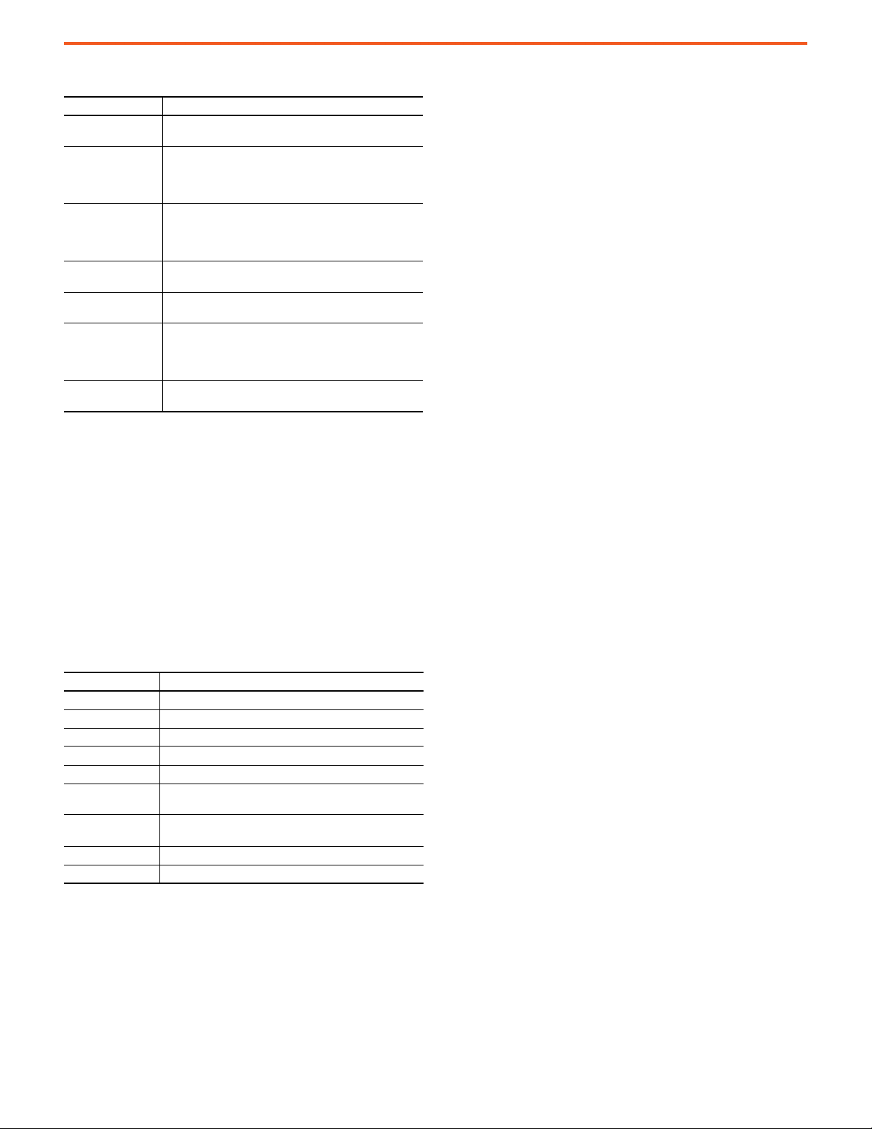
Communication Parameters
Table 1 - Specifications
Specifications Attributes
IO-Link revision V1.1
Process data in length 48 bits (6 bytes)
Process data out length Not available
Communication mode COM2 (38.4 kbps)
Cycle time, mi n 4 ms
Vend or ID 2 (0x0 2)
Device ID
SIO mode Supported
Data storage Not supported
294: 46CLR-D5LAC1-D5
295: 46CLR-D5LAC2-D5
296: 46CLR-D5LAC3-D5
Process Data In (Continuous Data)
Process Data In is transmitted cyclically to the IO-Link master from
the IO-Link device.
Page 2
ColorSight IO-Link
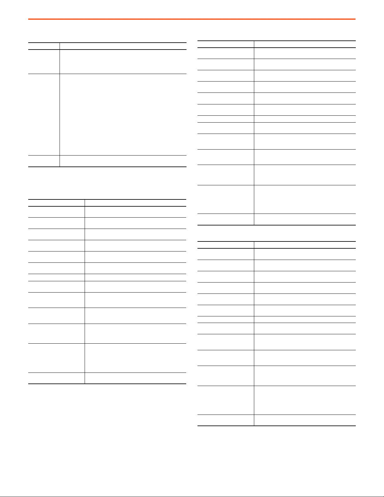
Process Data-in Parameter Definitions
Parameter Definition
Triggered1…7
SignalQualityScore
Signal Quality
Red
Green
Blue
Intensity
Performs the same operation as the discrete output for all
seven color channels.
Can be used to indicate if the signal strength is higher or
lower than a defined threshold in index 196 (0xC4). It also
helps you detect a reflectivity of a target that can affect
the performance of the sensor.
Reflects the strength of the return signal reflected from
the target. The range is 0…100%. Darker targets reflect a
value closer to zero while highly reflective targets reflect a
number closer to 100%.
Displays the red component of the color under detection.
The parameter can be a value between 0…4095.
Displays the green component of the color under
detection. The parameter can be a value between 0…4095.
Displays the red component of the color under detection.
The parameter can be a value between 0…4095. This value
is calculated by subtracting the green and red component
from the total value of 4095.
Displays the intensity of the color under detection. The
parameter can be a value of 0…4095.
Process Data Out (Continuous Data)
Not applicable.
Parameter Data (Asynchronous Data)
These parameters can be read from and/or written to an IO-Link
device. Unlike Process Data In, which is transmitted from the
IO-Link device to the IO-Link master cyclically, these parameters
are read or written on-request with the use of message
instructions.
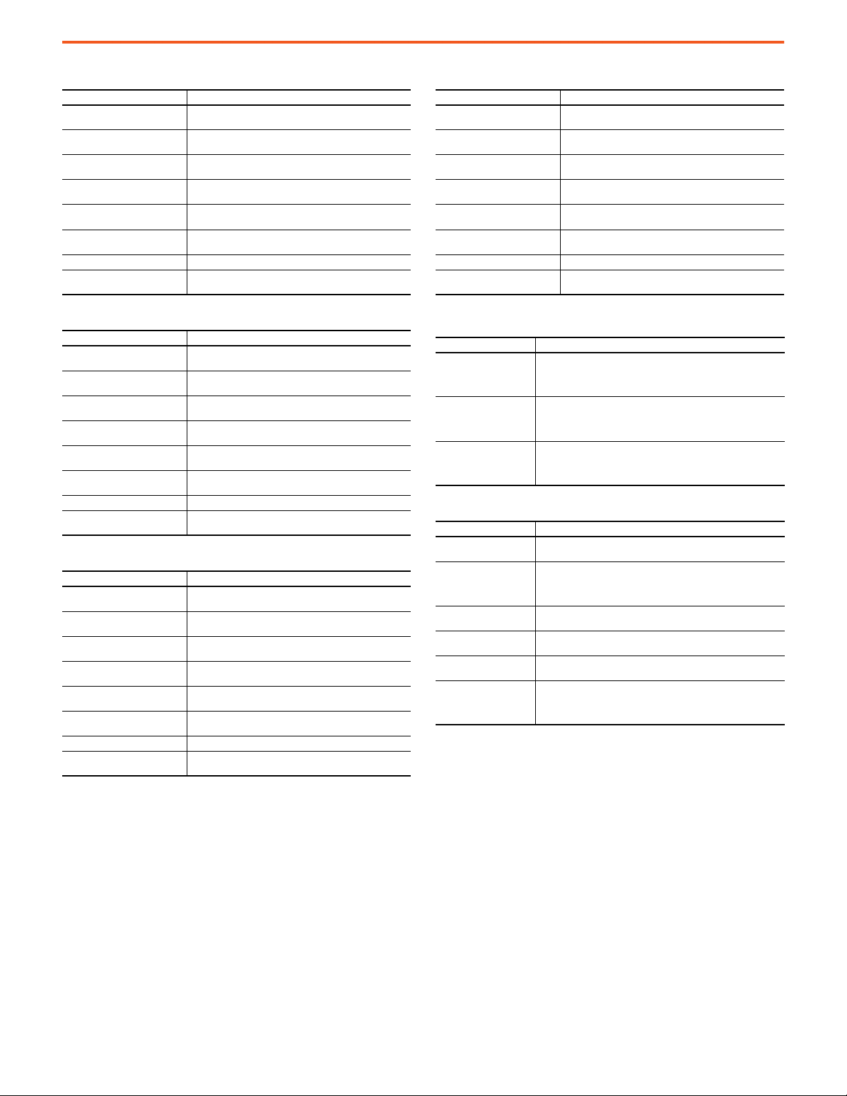
Identification Tab Definitions
Tab Definition
Vendor Name The vendor name of the product.
Product Name The product catalog number.
Product Text A brief description of the sensor.
Product ID The ordering part number of the sensor.
Serial Number The serial number of the unit.
Application Specific
Tag
Sensor
Hardware Revision The hardware revision of the sensor.
Firmware Revision The firmware revision of the sensor.
Allows you to assign a value to describe the sensor in the
application. For example, “roll level.
When used in the Add-on Profile (AOP), this value must not
be empty as it could cause a loss in communications.
Standard Teach Parameter Tab Definitions
This section captures the standard teach procedure of 46CLR
sensor. These steps show you how to teach the sensor in standard
teach mode.
1. Select the desired color channel to teach using the “Teach
Channel” (index: 203) parameter.
2. Click Apply in the AOP to set the desired color channel.
3. Place the target in front of the sensor. Send the command
“Standard Teach – Show Color” (index: 65) to start the teach
process.
4. Send the command “Teach – Apply” (index:
64) to finalize the
teach process.
5. The teach process is complete.
When using the AOP for 46CLR sensor, you must click the Refresh
button for the color setpoints to be updated in the AOP. After you
click Refresh in the AOP, the sensor correlation window opens and
asks you to validate the settings. Select “Use Device Values” and
then click OK. Click Apply in the AOP to save these settings.
Color Scan Teach Definitions
This section captures the color scan teach process of 46CLR sensor.
The Color Scan feature enables you to teach and detect objects with
various colors and individual colors to each channel. These steps show
you how to teach the sensor in color scan mode.
1. Select the desired color channel to teach using the “Teach
Channel” (index: 203) parameter.
2. Click Apply in the AOP to set the desired color channel.
3. Place the target in front of the field of view of the sensor and
send the command “Color Scan – Start” (index: 71). Move the
color targets that you want to teach as needed until all
desired colors are presented in the field of view of the
sensor.
4. Send the command “Color Scan – Stop” (index: 72) to stop the
color scan process.
5. Send the command “Teach – Apply” (index: 64) to finalize the
teach process.
6. The teach process in complete.
When using the AOP for 46CLR sensor, you must click Refresh for
the color setpoints to be updated in the AOP. After you click Refresh
in the AOP, the sensor correlation window opens and asks you to
validate the settings. Select “Use Device Values” and then click OK.
Click Apply in the AOP to save these settings.
2 Rockwell Automation Publication 46CLR-QR001C-EN-P - November 2020
Page 3
ColorSight IO-Link
Teach (Standard, Color Scan)
Parameter Definition
Selects the desired teach channel for the target in front of the field of view of the
Teach Channel
(203/0xCB)
Detection Mode
(177/0xB1)
Tea ch St atus
(204/0xCC)
sensor. The sensor has a total of seven color channels, three of which are discrete
and the remaining four are virtual channels. The default value for this parameter is
Channel 1 and must be changed to the desired color channel during the Standard or
Color Scan Teach Process.
Selects the desired color detection mode. The 46CLR ColorSight sensor uses these
main methods of color evaluation:
• Color Mode: This mode is optimized for the precise evaluation of several colors
or gradient of colors within a given tolerance (up to nine tolerance levels). In this
color inspection and evaluation mode, at least one color must be taught and
there’s no need to teach the background to be sure of reliable operation. This
method of operation is the most common.
• Best Fit Mode: This parameter value enables the sensor to operate as a color
sorting and assignment mode. In this mode, the sensor assigns the color that is
measured into the color channel that is closest to the internal set color. Multiple
colors must be taught and the background must also be taught using one of the
available color channels. This mode is uncommon and is only recommended for
advanced special applications.
• Teach Apply: Finalizes the standard teach and color scan teach process.
• Teach Cancel: Cancels the standard teach and color scan teach process without
completing the teach process.
• Reset – Color Channel: Resets the currently selected color channel to the factory
default settings.
Indicates the status of the teach process.
Operation Configuration
Triggered1 – Color Channel 1
Parameter Definition
• Channel 1. Red
• Channel 1. Green
Channel 1. Intensity
• Channel 1. Red Tolerance
• Channel 1. Green Tolerance
Channel 1. Intensity Tolerance
Channel 1. Tolerance
Channel 1. Polarity
Channel 1. Operation Enables or disables the operation of Channel 1.
Channel 1. Intensity Evaluation
Channel 1. Counter
Channel 1. On Delay
Channel 1. Off Delay
Channel 1. One Shot
Channel 1. Combine Color Channel
Sets the color threshold for the respective color. The parameter
can be a value between 0…4095.
Sets the color threshold for the Intensity. The parameter can be a
value between 0…4095.
Sets the color threshold tolerance for the respective color. The
parameter can be a value between 0…4095.
Sets the color threshold tolerance for the intensity. The parameter
can be a value between 0…4095.
Sets the color tolerance levels for Channel 1. The operator can set
zero as the finest tolerance while level nine is the widest tolerance.
Sets the polarity of the Color Channel 1. The polarity could be either
not inverted or inverted
Enables or disables the sensor to consider evaluating the intensity
of the color as part of the color detection.
Defines the desired number of counts for the discrete output to
turn ON. For example, if the counter value is set to 3, the output
turns ON after the third detection has occurred.
Defines the desired delay for the output to turn ON once a target
has been detected. For example, if the ON Delay value is 5000 ms
(5 s), the sensor output turns ON after 5 seconds have passed.
Defines the desired delay for the output to turn OFF once a target
has left the detection area. For example, if the OFF Delay value is
5000 ms (5 s), the sensor output turns ON immediately and then it
turns OFF after 5 seconds have passed.
The One Shot defines the width of the pulse of the output. For
example, if the One Shot value is set to 5000 ms (5 s), the output
turns ON immediately after the target has been detected and
remains on for 5 seconds. This value cannot be reset when a new
target is detected. And if a target is detected while the pulse is
active, it does not extend the output pulse.
Enables you to perform logic functions such as AND /OR with Color
Channel 4.
Triggered2 – Color Channel 2
Parameter Definition
•Channel 2. Red
• Channel 2. Green
Channel 2. Intensity
• Channel 2. Red Tolerance
• Channel 2. Green Tolerance
Channel 2. Intensity Tolerance
Channel 2. Tolerance
Channel 2. Polarity
Channel 2. Operation Enables or disables the operation of Channel 2.
Channel 2. Intensity Evaluation
Channel 2. Counter
Channel 2. On Delay
Channel 2. Off Delay
Channel 2. One Shot
Channel 2. Combine Color Channel
Sets the color threshold for the respective color. The parameter
can be a value between 0…4095.
Sets the color threshold for the Intensity. The parameter can be a
value between 0…4095.
Sets the color threshold tolerance for the respective color. The
parameter can be a value between 0…4095.
Sets the color threshold tolerance for the Intensity. The parameter
can be a value between 0…4095.
Sets the color tolerance levels for Channel 2. The operator can set
zero as the finest tolerance while level nine is the wide st tolerance.
Sets the polarity of the Color Channel 2. The polarity could be either
inverted or not inverted.
Enables or disables the sensor to consider evaluating the intensity
of the color as part of the color detection.
Defines the desired number of counts for the d iscrete output to
turn ON. For example, if the counter value is set to 3, the output
turns ON after the third detection has occurred.
Defines the desired delay for the output to turn ON once a target
has been detected. For example, if the ON Delay value is 5000 ms
(5 s), the sensor output turns ON after 5 seconds have passed.
Defines the desired delay for the output to turn OFF once a target
has left the detection area. For example, if the OFF Delay value is
5000 ms (5 s), the sensor output turns ON immediately and then it
turns OFF after 5 seconds have passed.
The One Shot defines the width of the pulse of the output. For
example, if the One Shot value is set to 5000 ms (5 s), the output
turns ON immediately after the target has been detected and
remains on for 5 seconds. This value cannot be reset when a new
target is detected. And if a target is detected while the pulse is
active, it does not extend the output pulse.
Enables you to perform logic functions such as AND /OR with Color
Channel 5.
Triggered3 – Color Channel 3
Parameter Definition
•Channel 3. Red
•Channel 3. Green
Channel 3. Intensity
• Channel 3. Red Tolerance
• Channel 3. Green Tolerance
Channel 3. Intensity Tolerance
Channel 3. Tolerance
Channel 3. Polarity
Channel 3. Operation Enables or disables the operation of Channel 3.
Channel 3. Intensity Evaluation
Channel 3. Counter
Channel 3. On Delay
Channel 3. Off Delay
Channel 3. One Shot
Channel 3. Combine Color Channel
Sets the color threshold for the respective color. The parameter
can be a value between 0…4095.
Sets the color threshold for the Intensity. The parameter can be a
value between 0…4095.
Sets the color threshold tolerance for the respective color. The
parameter can be a value between 0…4095.
Sets the color threshold tolerance for the Intensity. The parameter
can be a value between 0…4095.
Sets the color tolerance levels for Channel 3. The operator can set
zero as the finest tolerance while level nine is the widest tolerance.
Sets the po larity of the Color C hannel 3. It can be ei ther inverted or
not inverted.
Enables or disables the sensor to consider evaluating the intensity
of the color as part of the color detection.
Defines the desired number of counts for the d iscrete output to
turn ON. For example, if the counter value is set to 3, the output
turns ON after the third detection has occurred.
Defines the desired delay for the output to turn ON once a target
has been detected. For example, if the ON Delay value is 5000 ms
(5 s), the sensor output turns ON after 5 seconds have passed.
Defines the desired delay for the output to turn OFF once a target
has left the detection area. For example, if the OFF Delay value is
5000 ms (5 s), the sensor output turns ON immediately and then it
turns OFF after 5 seconds have passed.
Defines the width of the pulse of the output. For example, if the
One Shot value is set to 5000 ms (5 s), the output turns ON
immediately after the target has been detected and remains on fo r
5 seconds. This value cannot be reset when a new target is
detected. And if a target is detected while the pulse is active, it
does not extend the output pulse.
Enables you to perform logic functions such as AND/OR with Color
Channel 6.
Rockwell Automation Publication 46CLR-QR001C-EN-P - November 2020 3
Page 4
ColorSight IO-Link
Triggered4 – Color Channel 4
Parameter Definition
• Channel 4. Red
• Channel 4. Green
Channel 4. Intensity
• Channel 4. Red Tolerance
• Channel 4. Green Tolerance
Channel 4. Intensity Tolerance
Channel 4. Tolerance
Channel 4. Polarity
Channel 4. Operation Enables or disables the operation of Channel 3.
Channel 4. Intensity Evaluation
Sets the color threshold for the respective color. The parameter
can be a value between 0…4095.
Sets the color threshold for the Intensity. The parameter can be a
value between 0…4095.
Sets the color threshold tolerance for the respective color. The
parameter can be a value between 0…4095.
Sets the color threshold tolerance for the Intensity. Th e parameter
can be a value between 0…4095.
Sets the color tolerance levels for Channel 3. The operator can set
zero as the finest tolerance while level nine is the widest tolerance.
Sets the polarity of the Color Channel 3. The polarity could be
either inverted or not inverted
Enables or disables the sensor to consider evaluating the intensity
of the color as part of the color detection.
Triggered5 – Color Channel 5
Parameter Definition
• Channel 5. Red
• Channel 5. Green
Channel 5. Intensity
• Channel 5. Red Tolerance
• Channel 5. Green Tolerance
Channel 5. Intensity Tolerance
Channel 5. Tolerance
Channel 5. Polarity
Channel 5. Operation Enables or disables the operation of Channel 3.
Channel 5. Intensity Evaluation
Sets the color threshold for the respective color. The parameter
can be a value between 0…4095.
This parameter sets the color threshold for the Intensity. The
parameter can be a value between 0…4095.
Sets the color threshold tolerance for the respective color. The
parameter can be a value between 0…4095.
Sets the color threshold tolerance for the Intensity. Th e parameter
can be a value between 0…4095.
Sets the color tolerance levels for Channel 3. The operator can set
zero as the finest tolerance while level nine is the widest tolerance.
Sets the polarity of color channel 3. The polarity could be either
inverted or not inverted.
Enables or disables the sensor to consider evaluating the intensity
of the color as part of the color detection.
Triggered6 – Color Channel 6
Parameter Definition
• Channel 6. Red
• Channel 6. Green
Channel 6. Intensity
• Channel 6. Red Tolerance
• Channel 6. Green Tolerance
Channel 6. Intensity Tolerance
Channel 6. Tolerance
Channel 6. Polarity
Channel 6. Operation Enables or disables the operation of Channel 3.
Channel 6. Intensity Evaluation
Sets the color threshold for the respective color. The parameter
can be a value between 0…4095.
Sets the color threshold for the Intensity. The parameter can be a
value between 0…4095.
Sets the color threshold tolerance for the respective color. The
parameter can be a value between 0…4095.
Sets the color threshold tolerance for the Intensity. Th e parameter
can be a value between 0…4095.
Sets the color tolerance levels for Channel 3. The operator can set
zero as the finest tolerance while level nine is the widest tolerance.
Sets the polarity of the Color Channel 3. The polarity could be
either inverted or not inverted
Enables or disables the sensor to consider evaluating the intensity
of the color as part of the color detection.
Triggered7 – Color Channel 7
Parameter Definition
•Channel 7. Red
•Channel 7. Green
Channel 7. Intensity
• Channel 7. Red Tolerance
• Channel 7. Green Tolerance
Channel 7. Intensity Tolerance
Channel 7. Tolerance
Channel 7. Polarity
Channel 7. Operation Enables or disables the operation of Channel 3.
Channel 7. Intensity Evaluation
Sets the color threshold for the respective color. The parameter
can be a value between 0…4095.
Sets the color threshold for the Intensity. The parameter can be a
value between 0…4095.
Sets the color threshold tolerance for the respective color. The
parameter can be a value between 0…4095.
Sets the color threshold tolerance for the Intensity. The parameter
can be a value between 0…4095.
Sets the color tolerance levels for Channel 3. The operator can set
zero as the finest tolerance while level nine is the widest tolerance.
Sets the polarity of the Color Channel 3. The polarity could be
either inverted or not inverted
Enables or disables the sensor to consider evaluating the intensity
of the color as part of the color detection.
Trigger
Parameter Definition
Simulates that the trigger is OFF or disabled, which means that the sensor
Trigger OFF
Trigger ON
Trigger Input
Sensor Configuration
Parameter Definition
Discrete Output Type
Averaging Filter
Binary Outputs
Display Screensaver
Display Indication
Data Mapping Configuration
These process data maps are offered in the 46CLR sensor:
• Data Map 0 (Default): Triggered, Quality Score, Signal
• Data Map 1: Red, Green, Blue, Intensity
stops measuring the sensor under detection. For this parameter to
operate, pin 2 operation from Channel 2 should be changed to Input
(Trigger) that the sensor operates as an input.
Simulates that the trigger is ON or enabled, which means that the sensor
stops measuring the sensor under detection. For this parameter to
operate, pin 2 operation from Channel 2 should be changed to Input
(Trigger) that the sensor operates as an input.
Enables the input of an external sensor that is connected to pin 2 sensor to
enable or disable sensor measurement. When the pin is connected to high,
the color sensor measurement occurs as long as the Trigger sensor output
is high.
Changes the output type to operate either as PNP, NPN, or Auto PNP/NPN
only on pin 4 (Triggered1).
Parameter allows operators to average multiple measurements inside of
the sensor with the goal of providing a more stable color evaluation. You
can choose between 1…100 measurements to average the measured
signal. The higher the measurement the more stable the measured output.
Disables or enables the logical combination of several channels. The
default value for this parameter is disabled.
Enables or disables the LCD display screensaver function. The default
value for this parameter is enabled.
Controls the rotation of the LCD display on the sensor. A value of 0 rotates
the display 180°.
In this section, the operator is able to configure the combination of
parameters that must be displayed as process data. 46CLR sensor process
data consists of 5 bytes of data with multiple parameters to be presented
to the operator.
4 Rockwell Automation Publication 46CLR-QR001C-EN-P - November 2020
Page 5

Diagnosis Tab Definitions — Device Access Locks
Parameter Definition
Data Storage Lock Enables or disables the data storage functionality that is tied to the sensor.
Local User Interface Lock
Service Function
Parameter Definition
Device Reset Performs a soft reset of the sensor. This reset is similar to powering the sensor ON or OFF.
Restore Factory Settings
Location Indication
Emitter OFF
Emitter ON Enables operators to turn ON the white LED light source.
Event Enable. Event Enable Enables or disables sensor events.
Operating Hours – Since
Inception
Detection Counter – Since
Inception
Internal Temperature
Actual - Since Power Up Reflects the current temperature inside of the microprocessor die of the sensor.
Maximum/Minimum —
Since Power Up
Maximum/Minimum —
Since Inception
Maximum/Minimum –
Temp erat ure Limi t
Locks the local push button on the sensor. The push button can be unlocked locally
following the unlock procedure.
This setting is a write-only command and sets the current sensor settings to their factory
default values.
Allows you to set the Local User Interface on 46CLRF sensor to perform the location
indication function. If this command is only sent once in a period of 1 second, the indicator
remains ON for up to 60 seconds. If this command is sent twice in less than 1 second, the
sensor flashes permanently until you send the command three times in less than 1 second
to stop the intermittent location indication flashing.
Enables you to turn OFF the white light-emitting diode (LED) light source. This setting may
be a desirable feature in some applications where you want to disable the light source due
to concerns with the light source.
Displays the number of hours that the sensor has been continuously in operation. This
parameter is valuable as it can serve as a diagnostic parameter for troubleshooting
applications if there are repeated failures.
Displays the number of targets that have been detected since the sensor has been in
operation.
Displays the internal temperature information available in the sensor. These parameters do
not reflect the ambient temperature, however, it can be used to infer if the environment in
the application is getting either too cold or too hot. This information could be used for
application troubleshooting purposes.
Reflects the maximum/minimum temperature inside of the microprocessor die of the
sensor since the last power up.
Reflects the maximum/minimum temperature inside of the microprocessor die of the
sensor since inception.
Reflects the maximum/minimum temperature limit before enabling a high/low
temperature event.
ColorSight IO-Link
Rockwell Automation Publication 46CLR-QR001C-EN-P - November 2020 5
Page 6

ColorSight IO-Link
Triggered4
31 30 29 28 27 26 25 24 23 22 21 20 19 18 17 16 15 14 13 12 11 10 9 8 7 6 5 4 3 2 1 0
76543210765432107654321076543210
MSB D7D6D5D4D3D2D1
LSB D0
MSB D7D6D5D4D3D2D1
LSB D0
MSB D7D6D5D4D3D2D1
LSB D0
MSB D7D6D5D4D3D2D1
LSB D0
SignalQuality
Triggered2
Triggered1
Byte 0
Byte 1
Byte 2
Byte 3
Triggered3
23 22 21 20 19 18 17 16
76543210
MSB D7
D6D5D4D3D2D1LSB D0
Byte 1
23 22 21 20 19 18 17 16
76543210
MSB D7D6D5D4D3D2D1
LSB D0
Byte 1
Triggered6
Triggered5
Triggered7
SignalQualityScore
31 30 29 28 27 26 25 24 23 22 21 20 19 18 17 16 15 14 13 12 11 10 9 8 7 6 5 4 3 2 1 0
76543210765432107654321076543210
MSB D7D6D5D4D3D2D1
LSB D0
MSB D7D6D5D4D3D2D1
LSB D0
MSB D7D6D5D4D3D2D1
LSB D0
MSB D7D6D5D4D3D2D1
LSB D0
Red
Byte 0
Byte 1
Byte 2
Byte 3
23 22 21 20 19 18 17 16
76543210
MSB D7
D6D5D4D3D2D1LSB D0
Byte 4
23 22 21 20 19 18 17 16
76543210
MSB D7D6D5D4D3D2D1
LSB D0
Byte 5
GreenBlueIntensity
Table 2 - Process Data Map 0 — Triggered, Quality Score, Signal Quality
Table 3 - Process Data Map 1 — Red, Green, Blue, and Intensity
Table 4 - Identification Tab
Index (Dec/Hex) Access Data Length Sub-Index Description Information
Device Information
16/ 0x10 Read-only String 64 bytes Vendor Name Allen-Bradley
17/ 0x11 Read-only String 64 bytes Vendor Text
18/ 0x12 Read-only String 64 bytes Product Name 46CLR-D5LACx-D5 Ser. A
19/ 0x13 Read-only String 64 bytes Product Text Photo Sensor, True Color, …
21/ 0x15 Read-only String 64 bytes Serial Number 701781-000011
User Specific Information
24/ 0x18 Read/write String 32 bytes Application-specific Tag 46CLR sensor
Revision Information
22/x016 Read/write String 32 bytes Hardware Revision 1.0
23/0x17 Read/write String 32 bytes Firmware Revision 1.0
Visit rockwellautomation.com/en-us/products/hardware/allen-
bradley/sensors-and-switches.html
Table 5 - Parameter Tab
Index (Dec/Hex) Access Data Length Sub-Index Description Range Default Value/ Description
Teach-In Operation — Standard Teach
2/0x02 Write-only UInteger 8 bits Standard Teach - Show Color 65/0x41
Teach-In Operation — Color Scan Teach
2/0x02 Write-only UInteger 8 bits Color Scan – Start 71/0x47
2/0x02 Write-only UInteger 8 bits Color Scan – Stop 72/0x48
Teach-In Operation — Teach (Standard, Color Scan)
1 – Color Channel 1
2 – Color Channel 2
203/0xCB Read/write UInteger 8 bits Teach Channel 1…7
177/0xB1 Read/write UInteger 8 bits Detection Mode 0 or 1
2/0x02 Read/write UInteger 8 bits Teach – Apply 64/0x40
2/0x02 Read/write UInteger 8 bits Teach – Cancel 79/0x4F
2/0x02 Read/write UInteger 8 bits Reset – Color Channel 162/0xA2
204/0xCC Read-only UInteger 4 bits Teach Status 0…7
3 – Color Channel 3
4 – Color Channel 4
5 – Color Channel 5
6 – Color Channel 6
7 – Color Channel 7
0 – Color Mode (Default)
1 – Best Fit Mode
0 – Teach Status Idle
1 – Teach Status Successful
2 – Teach Status Successful
4 – Waiting for Teach
5 – Busy
6 – Teach Error
6 Rockwell Automation Publication 46CLR-QR001C-EN-P - November 2020
Page 7
Table 5 - Parameter Tab (Continued)
Index (Dec/Hex) Access Data Length Sub-Index Description Range Default Value/ Description
Operation Configuration — Triggered1 – Color Channel 1
128/0x80 Read/write RecordT 96 Bits
Offset: 80 Read/write UInteger 16 bits 1 Channel 1. Red 0…4095 1365 (33.33 expressed as percentage)
Offset: 64 Read/write UInteger 16 bits 2 Channel 1. Green 0…4095 1365 (33.33 expressed as percentage)
Offset: 48 Read/write UInteger 16 bits 3 Channel 1. Intensity 0…4095 4095 (100 expressed as percentage)
Offset: 32 Read/write UInteger 16 bits 4 Channel 1. Red Tolerance 0…4095 65 (1.59 expressed as percentage)
Offset: 16 Read/write UInteger 16 bits 5 Channel 1. Green Tolerance 0…4095 65 (1.59 expressed as percentage)
Offset: 0 Read/write UInteger 16 bits 6 Channel 1. Intensity Tolerance 0…4095 75 (1.83 expressed as percentage)
96/0x60 Read/write RecordT 104 bits
Offset: 96 Read/write UInteger 8 bits 1 Channel 1. Tolerance 0…8
Offset: 88 Read/write UInteger 8 bits 2 Channel 1. Polarity 0…1
Offset: 80 Read/write UInteger 8 bits 3 Channel 1. Operation 0…1
Offset: 72 Read/write UInteger 8 bits 4 Channel 1. Intensity Evaluation 0…1
Offset: 56 Read/write UInteger 16 bits 5 Channel 1. Counter 0…65535 0 in ms
Offset: 40 Read/write UInteger 16 bits 6 Channel 1. On Delay 0…65535 0 in ms
Offset: 24 Read/write UInteger 16 bits 7 Channel 1. Off Delay 0…65535
Offset: 8 Read/write UInteger 16 bits 8 Channel 1. One Shot 0…65535
Offset: 0 Read/write UInteger 8 bits 9 Channel 1. Combine Color Channel 0…2
Operation Configuration — Triggered2 – Color Channel 2
129/0x81 Read/write RecordT 96 Bits
Offset: 80 Read/write UInteger 16 bits 1 Channel 2. Red 0…4095 1365 (33.33 expressed as percentage)
Offset: 64 Read/write UInteger 16 bits 2 Channel 2. Green 0…4095 1365 (33.33 expressed as percentage)
Offset: 48 Read/write UInteger 16 bits 3 Channel 2. Intensity 0…4095 4095 (100 expressed as percentage)
Offset: 32 Read/write UInteger 16 bits 4 Channel 2. Red Tolerance 0…4095 65 (1.59 expressed as percentage)
Offset: 16 Read/write UInteger 16 bits 5 Channel 2. Green Tolerance 0…4095 65 (1.59 expressed as percentage)
Offset: 0 Read/write UInteger 16 bits 6 Channel 2. Intensity Tolerance 0…4095 75 (1.83 expressed as percentage)
97/0x61 Read/write RecordT 104 bits
Offset: 96 Read/write UInteger 8 bits 1 Channel 2. Tolerance 0…8
Offset: 88 Read/write UInteger 8 bits 2 Channel 2. Polarity 0 or 1
Offset: 80 Read/write UInteger 8 bits 3 Channel 2. Operation 0 or 1
Offset: 72 Read/write UInteger 8 bits 4 Channel 2. Intensity Evaluation 0 or 1
Offset: 56 Read/write UInteger 16 bits 5 Channel 2. Counter 0…65535 0 in ms
Offset: 40 Read/write UInteger 16 bits 6 Channel 2. On Delay 0…65535 0 in ms
Offset: 24 Read/write UInteger 16 bits 7 Channel 2. Off Delay 0…65535 0 in ms
Offset: 8 Read/write UInteger 16 bits 8 Channel 2. One Shot 0…65535 0 in ms
Offset: 0 Read/write UInteger 8 bits 9 Channel 2. Combine Color Channel 0…2
0 – Tolerance Level 1 – Finest Tolerance
3 – Tolerance Level 4 (Default)
8 – Tolerance Level 9 – Widest Tolerance
0 – Not Inverted (Default)
1 – Inverted
0 – Disabled (Default)
1 – Enabled
0 – Off
1 – On (Default)
0 – Not Connected
1 – Combine with Color C4 (AND Logic)
2 – Exclude Color C4 (OR Logic)
0 – Tolerance Level 1 – Finest Tolerance
3 – Tolerance Level 4 (Default)
8 – Tolerance Level 9 – Widest Tolerance
0 – Not Inverted (Default)
1 – Inverted
0 – Disabled (Default)
1 – Enabled
0 – Off
1 – On (Default)
0 – Not Connected
1 – Combine with Color C5 (AND Logic)
2 – Exclude Color C5 (OR Logic)
ColorSight IO-Link
Rockwell Automation Publication 46CLR-QR001C-EN-P - November 2020 7
Page 8

ColorSight IO-Link
Table 5 - Parameter Tab (Continued)
Index (Dec/Hex) Access Data Length Sub-Index Description Range Default Value/ Description
Operation Configuration — Triggered3 – Color Channel 3
130/x082 Read/write RecordT 96 bits
Offset: 80 Read/write UInteger 16 bits 1 Channel 3. Red 0…4095 1365 (33.33 expressed as percentage)
Offset: 64 Read/write UInteger 16 bits 2 Channel 3. Green 0…4095 1365 (33.33 expressed as percentage)
Offset: 48 Read/write UInteger 16 bits 3 Channel 3. Intensity 0…4095 4095 (100 expressed as percentage)
Offset: 32 Read/write UInteger 16 bits 4 Channel 3. Red Tolerance 0…4095 65 (1.59 expressed as percentage)
Offset: 16 Read/write UInteger 16 bits 5 Channel 3. Green Tolerance 0…4095 65 (1.59 expressed as percentage)
Offset: 0 Read/write UInteger 16 bits 6 Chanel 3. Intensity Tolerance 0…4095 75 (1.83 expressed as percentage)
98/0x62 Read/write RecordT 104 bits
Offset: 96 Read/write UInteger 8 bits 1 Channel 3. Tolerance 0…8
Offset: 88 Read/write UInteger 8 bits 2 Channel 3. Polarity 0 or 1
Offset: 80 Read/write UInteger 8 bits 3 Channel 3. Operation 0 or 1
Offset: 72 Read/write UInteger 8 bits 4 Chanel 3. Int ensity Evaluation 0 or 1
Offset: 56 Read/write UInteger 16 bits 5 Channel 3. Counter 0…65535 0 in ms
Offset: 40 Read/write UInteger 16 bits 6 Channel 3. On Delay 0…65535 0 in ms
Offset: 24 Read/write UInteger 16 bits 7 Channel 3. Off Delay 0…65535 0 in ms
Offset: 8 Read/write UInteger 16 bits 8 Channel 3. One Shot 0…65535 0 in ms
Offset: 0 Read/write UInteger 8 bits 9 Channel 3. Combine Color Channel 0…2
Operation Configuration — Triggered4 – Color Channel 4
131/0x83 Read/write RecordT 96 bits
Offset: 80 Read/write UInteger 16 bits 1 Channel 4. Red 0…4095 1365 (33.33 expressed as percentage)
Offset: 64 Read/write UInteger 16 bits 2 Channel 4. Green 0…4095 1365 (33.33 expressed as percentage)
Offset: 48 Read/write UInteger 16 bits 3 Channel 4. Intensity 0…4095 4095 (100 expressed as percentage)
Offset: 32 Read/write UInteger 16 bits 4 Channel 4. Red Tolerance 0…4095 65 (1.59 expressed as percentage)
Offset: 16 Read/write UInteger 16 bits 5 Channel 4. Green Tolerance 0…4095 65 (1.59 expressed as percentage)
Offset: 0 Read/write UInteger 16 bits 6 Channel 4. Intensity Tolerance 0…4095 75 (1.83 expressed as percentage)
99/0x83 Read/write RecordT 32 bits
Offset: 24 Read/write UInteger 8 bits 1 Channel 4. Tolerance 0…8
Offset: 16 Read/write UInteger 8 bits 2 Channel 4. Polarity 0 or 1
Offset: 8 Read/write UInteger 8 bits 3 Channel 4. Operation 0 or 1
Offset: 0 Read/write UInteger 8 bits 4 Channel 4. Intensity Evaluation 0 or 1
Operation Configuration — Triggered5 – Color Channel 5
132/0x84 Read/write RecordT 96 Bits
Offset: 80 Read/write UInteger 16 bits 1 Channel 5. Red 0…4095 1365 (33.33 expressed as percentage)
Offset: 64 Read/write UInteger 16 bits 2 Channel 5. Green 0…4095 1365 (33.33 expressed as percentage)
Offset: 48 Read/write UInteger 16 bits 3 Channel 5. Intensity 0…4095 4095 (100 expressed as percentage)
Offset: 32 Read/write UInteger 16 bits 4 Channel 5. Red Tolerance 0…4095 65 (1.59 expressed as percentage)
Offset: 16 Read/write UInteger 16 bits 5 Channel 5. Green Tolerance 0…4095 65 (1.59 expressed as percentage)
Offset: 0 Read/write UInteger 16 bits 6 Channel 5. Intensity Tolerance 0…4095 75 (1.83 expressed as percentage)
100/0x64 Read/write RecordT 32 bits
Offset: 24 Read/write UInteger 8 bits 1 Chanel 5. Tolerance 0…8
Offset: 16 Read/write UInteger 8 bits 2 Channel 5. Polarity 0 or 1
Offset: 8 Read/write UInteger 8 bits 3 Chanel 5. Operation 0 or 1
Offset: 0 Read/write UInteger 8 bits 4 Channel 5. Intensity Evaluation 0 or 1
0 – Tolerance Level 1 – Finest Tolerance
3 – Tolerance Level 4 (Default)
8 – Tolerance Level 9 – Widest Tolerance
0 – Not Inverted
1 – Inverted
0 – Disabled (Default)
1 – Enabled
0 – Off
1 – On (Default)
0 – Not Connected
1 – Combine with Color C6 (AND Logic)
2 – Exclude Color C6 (OR Logic)
0 – Tolerance Level 1 – Finest Tolerance
3 – Tolerance Level 4 (Default)
8 – Tolerance Level 9 – Widest Tolerance
0 – Not Inverted
1 – Inverted
0 – Disabled (Default)
1 – Enabled
0 –Off
1 – On (Default)
0 – Tolerance Level 1 – Finest Tolerance
3 – Tolerance Level 4 (Default)
8 – Tolerance Level 9 – Widest Tolerance
0 – Not Inverted (Default)
1 – Inverted
0 – Disabled (Default)
1 – Enabled
0 – Off
1 – On (Default)
8 Rockwell Automation Publication 46CLR-QR001C-EN-P - November 2020
Page 9

Table 5 - Parameter Tab (Continued)
Index (Dec/Hex) Access Data Length Sub-Index Description Range Default Value/ Description
Operation Configuration — Triggered6 – Color Channel 6
133/0x85 Read/write RecordT 96 Bits
Offset: 80 Read/write UInteger 16 bits 1 Channel 6. Red 0…4095 1365 (33.33 expressed as percentage)
Offset: 64 Read/write UInteger 16 bits 2 Channel 6. Green 0…4095 1365 (33.33 expressed as percentage)
Offset: 48 Read/write UInteger 16 bits 3 Channel 6. Intensity 0…4095 4095 (100 expressed as percentage)
Offset: 32 Read/write UInteger 16 bits 4 Channel 6. Red Tolerance 0…4095 65 (1.59 expressed as percentage)
Offset: 16 Read/write UInteger 16 bits 5 Channel 6. Green Tolerance 0…4095 65 (1.59 expressed as percentage)
Offset: 0 Read/write UInteger 16 bits 6 Channel 6. Intensity Tolerance 0…4095 75 (1.83 expressed as percentage)
101/0x65 Read/write RecordT 32 bits
Offset: 24 Read/write UInteger 8 bits 1 Channel 6. Tolerance
Offset: 16 Read/write UInteger 8 bits 2 Channel 6. Polarity 0 or 1
Offset: 8 Read/write UInteger 8 bits 3 Channel 6. Operation 0 or 1
Offset: 0 Read/write UInteger 8 bits 4 Channel 6. Intensity Evaluation 0 or 1
Operation Configuration — Triggered7 – Color Channel 7
134/0x86 Read/write RecordT 96 Bits
Offset: 80 Read/write UInteger 16 bits 1 Channel 7. Red 0…4095 1365 (33.33 expressed as percentage)
Offset: 64 Read/write UInteger 16 bits 2 Channel 7. Green 0…4095 1365 (33.33 expressed as percentage)
Offset: 48 Read/write UInteger 16 bits 3 Channel 7. Intensity 0…4095 4095 (100 expressed as percentage)
Offset: 32 Read/write UInteger 16 bits 4 Channel 7. Red Tolerance 0…4095 65 (1.59 expressed as percentage)
Offset: 16 Read/write UInteger 16 bits 5 Channel 7. Green Tolerance 0…4095 65 (1.59 expressed as percentage)
Offset: 0 Read/write UInteger 16 bits 6 Channel 7. Intensity Tolerance 0…4095 75 (1.83 expressed as percentage)
102/0x66 Read/write RecordT 32 bits
Offset: 24 Read/write UInteger 8 bits 1 Channel 7. Tolerance 0…8
Offset: 16 Read/write UInteger 8 bits 2 Channel 7. Polarity 0 or 1
Offset: 8 Read/write UInteger 8 bits 3 Channel 7. Operation 0 or 1
Offset: 0 Read/write UInteger 8 bits 4 Channel 7. Intensity Evaluation 0 or 1
Operation Configuration — Trigger
2/0x02 Write-only UInteger 8 bits Trigger OFF 171/0xAB
2/0x02 Write-only UInteger 8 bits Trigger ON 170/0xAA
2/x02 Write-only UInteger 8 bits Trigger Input Pin 169/0xA9
Sensor Configuration
176/0xB0 Read/write RecordT 24 bits
Offset: 16 Read/write UInteger 8 bits 1 Discrete Output Type 0…2
Offset: 8 Read/write UInteger 8 bits 2 Averaging Filter 0…6
Offset: 0 Read/write UInteger 8 bits 3 Binary Outputs 0 or 1
224/0xE0 RecordT UInteger 16 bits
Offset: 8 Read/write UInteger 8 bits 1 Display Screensaver 0 or 1
Offset: 0 Read/write UInteger 8 bits 2 Display Indication 0 or 1
Data Mapping Configuration
202/0xCA Read/write UInteger 8 bits Mode 0…1
0 – Tolerance Level 1 – Finest Tolerance
3 – Tolerance Level 4 (Default)
8 – Tolerance Level 9 – Widest Tolerance
0 – Not Inverted (Default)
1 – Inverted
0 – Disabled (Default)
1 – Enabled
0 – Off
1 – On (Default)
0 – Tolerance Level 1 – Finest Tolerance
3 – Tolerance Level 4 (Default)
8 – Tolerance Level 9 – Widest Tolerance
0 – Not Inverted (Default)
1 – Inverted
0 – Disabled (Default)
1 – Enabled
0 – Off
1 – On (Default)
Simulates that the trigger is OFF or disabled,
which means that the sensor stops measuring
the color under detection.
Simulates that the trigger is ON or enabled,
which means the sensor measures the color
This parameter enables pin 2 to operate as a
Trigger
0 – NPN Output
1- PNP Output (Default)
2 – Auto Detect on Triggered1
0 – 1000 Measurement
1 – 100 Measurements (Default)
2 – 30 Measurements
3 – 10 Measurements
4 – 6 Measurements
5 – 2 Measurements
6 – 1 Measurement
0 – Disabled (Default)
1 – Enabled
0 – Off
1 – On (Default)
0 – Rotate 180°
1– Default (Default)
0 – Triggered, Quality Score, Signal
1 – Red, Green, Blue, Intensity
ColorSight IO-Link
Rockwell Automation Publication 46CLR-QR001C-EN-P - November 2020 9
Page 10

ColorSight IO-Link
Table 6 - Diagnosis Tab
Index (Dec/Hex) Access Data Length Sub-Index Description Range Default Value/ Description
Device Access Locks
12/0x0C Read-only Boolean 1 bit 3 Device Access Locks. Data Storage Lock 0 or 1 0x00
12/0x0C Read/write Boolean 1 bit 4
Service Function
2/x0x02 Write-only UInteger 8 bits Device Reset 128/0x80
2/0x02 Write-only UInteger 8 bits Restore Factory Settings 130/0x82
2/0x02 Write-only UInteger 8 bits Location Indication 175/0xAF
2/0x02 Write-only UInteger 8 bits Emitter OFF 160/0xA0
2/0x02 Write-only UInteger 8 bits Emitter ON 161/0xA1
81/0x51 Read/write UInteger 8 bits Event Enable. Event Enable 0…31 See Table 7
Operation Information
88/0x67 Read-only RecordT 64 bits
Offset: 32 Read-only UInteger 32 bits 1 Operating Hours – Since Inception
Offset: 0 Read-only UInteger 32 bits 2 Detection Counter – Since Inception
196/0xC4 Read/write UInteger 8 bits Signal Quality Level 0…90 10
Internal Temperature
104/0x68 Read-only RecordT 40 bits
Offset: 32 Read-only Integer 8 bits 1 Actual – Since Power Up -400…+100
Offset: 24 Read-only Integer 8 bits 2 Maximum – Since Power Up -400…+100
Offset: 16 Read-only Integer 8 bits 3 Minimum – Since Power Up -400…+100
Offset: 8 Read-only Integer 8 bits 4 Maximum – Since Inception -400…+100
Offset: 0 Read-only Integer 8 bits 5 Minimum – Since Inception -400…+100
83/0x53 Read/write RecordT 16 bits
Offset: 16 Read/write Integer 8 bits 1 Maximum Temperature Limit -400…+100
Offset: 0 Read/write Integer 8 bits 2 Minimum Temperature Limit -400…+100
Communications Characteristics
0/0x00 RecordT RecordT 128 bits
Offset: 104 Read-only UInteger 8 bits 3 Direct Parameters. Min Cycle Time ms
Offset: 112 Read-only UInteger 8 bits 2 Direct Parameters. Master Cycle Time ms
Offset: 88 Read-only UInteger 8 bits 5 Direct Parameters.IO-Link Version ID
Device Access Locks. Local User
Interface Lock
0 or 1 0x00
Table 7 - Events
Event(Dec/Hex) Value Event Type Description R ange
20480/0x5000 Error Device Hardware Fault
20497/0x5011 Notification Nonvolatile memory loss
65425/0xFF91 Error Data storage – upload request
16384/0x4000 Error Temperature Fault
10 Rockwell Automation Publication 46CLR-QR001C-EN-P - November 2020
Page 11

Notes:
ColorSight IO-Link
Rockwell Automation Publication 46CLR-QR001C-EN-P - November 2020 11
Page 12

Rockwell Automation Support
Use these resources to access support information.
Technical Support Center Find help with how-to videos, FAQs, chat, user forums, and product notification updates. rok.auto/support
Knowledgebase Access Knowledgebase articles. rok.auto/knowledgebase
Local Technical Support Phone Numbers Locate the telephone number for your country. rok.auto/phonesupport
Literature Library Find installation instructions, manuals, brochures, and technical data publications. rok.auto/literature
Product Compatibility and Download Center
(PCDC)
Download firmware, associated files (such as AOP, EDS, and DTM), and access product
release notes.
rok.auto/pcdc
Documentation Feedback
Your comments help us serve your documentation needs better. If you have any suggestions on how to improve our content, complete the
form at rok.auto/docfeedback
.
Allen-Bradley, ColorSight, expanding human possibility, and Rockwell Automation are trademarks of Rockwell Automation, Inc.
Trademarks not belonging to Rockwell Automation are property of their respective companies.
Rockwell Automation maintains current product environmental compliance information on its website at rok.auto/pec.
Rockwell Otomasyon Ticaret A.Ş. Kar Plaza İş Merkezi E Blok Kat:6 34752, İçerenköy, İstanbul, Tel: +90 (216) 5698400 EEE Yönetmeliğine Uygundur
Publication 46CLR-QR001C-EN-P - November 2020
Supersedes Publication 46CLR-QR00 1B-EN-P - January 2020 Copyright © 2020 Rockwell Automation, Inc. All rights reserved. Printed in the U.S.A.
 Loading...