

Page 1

CENTERLINE 2500 Low
Voltage Motor Control Centers
Bulletin Number 2500
Installation Instructions
Original Instructions
Page 2
CENTERLINE 2500 Low Voltage Motor Control Centers Installation Instructions
Important User Information
Read this document and the documents listed in the additional resources section about installation, configuration, and
operation of this equipment before you install, configure, operate, or maintain this product. Users are required to familiarize
themselves with installation and wiring instructions in addition to requirements of all applicable codes, laws, and standards.
Activities including installation, adjustments, putting into service, use, assembly, disassembly, and maintenance are required to
be carried out by suitably trained personnel in accordance with applicable code of practice.
If this equipment is used in a manner not specified by the manufacturer, the protection provided by the equipment may be
impaired.
In no event will Rockwell Automation, Inc. be responsible or liable for indirect or consequential damages resulting from the use
or application of this equipment.
The examples and diagrams in this manual are included solely for illustrative purposes. Because of the many variables and
requirements associated with any particular installation, Rockwell Automation, Inc. cannot assume responsibility or liability for
actual use based on the examples and diagrams.
No patent liability is assumed by Rockwell Automation, Inc. with respect to use of information, circuits, equipment, or software
described in this manual.
Reproduction of the contents of this manual, in whole or in part, without written permission of Rockwell Automation, Inc., is
prohibited.
Throughout this manual, when necessary, we use notes to make you aware of safety considerations.
WARNING: Identifies information about practices or circumstances that can cause an explosion in a hazardous environment,
which may lead to personal injury or death, property damage, or economic loss.
ATTENTION: Identifies information about practices or circumstances that can lead to personal injury or death, property
damage, or economic loss. Attentions help you identify a hazard, avoid a hazard, and recognize the consequence.
IMPORTANT Identifies information that is critical for successful application and understanding of the product.
Labels may also be on or inside the equipment to provide specific precautions.
SHOCK HAZARD: Labels may be on or inside the equipment, for example, a drive or motor, to alert people that dangerous
voltage may be present.
BURN HAZARD: Labels may be on or inside the equipment, for example, a drive or motor, to alert people that surfaces may
reach dangerous temperatures.
ARC FLASH HAZARD: Labels may be on or inside the equipment, for example, a motor control center, to alert people to
potential Arc Flash. Arc Flash will cause severe injury or death. Wear proper Personal Protective Equipment (PPE). Follow ALL
Regulatory requirements for safe work practices and for Personal Protective Equipment (PPE).
2 Rockwell Automation Publication 2500-IN001F-EN-P - April 2021
Page 3

Table of Contents
Preface
About This Publication . . . . . . . . . . . . . . . . . . . . . . . . . . . . . . . . . . . . . . . . . . . 7
Download Firmware, AOP, EDS, and Other Files . . . . . . . . . . . . . . . . . . . . 7
Summary of Changes. . . . . . . . . . . . . . . . . . . . . . . . . . . . . . . . . . . . . . . . . . . . . 7
Additional Resources . . . . . . . . . . . . . . . . . . . . . . . . . . . . . . . . . . . . . . . . . . . . . 8
Chapter 1
System Overview ArcShield Rating . . . . . . . . . . . . . . . . . . . . . . . . . . . . . . . . . . . . . . . . . . . . . . . . . 9
IntelliCENTER Software. . . . . . . . . . . . . . . . . . . . . . . . . . . . . . . . . . . . . . . . . 10
IntelliCENTER Features. . . . . . . . . . . . . . . . . . . . . . . . . . . . . . . . . . . . . . 10
IntelliCENTER Software . . . . . . . . . . . . . . . . . . . . . . . . . . . . . . . . . . . . . 10
Structure. . . . . . . . . . . . . . . . . . . . . . . . . . . . . . . . . . . . . . . . . . . . . . . . . . . . . . . 11
Dimensions . . . . . . . . . . . . . . . . . . . . . . . . . . . . . . . . . . . . . . . . . . . . . . . . . 11
Typical Column Construction . . . . . . . . . . . . . . . . . . . . . . . . . . . . . . . . . . . . 13
Technical Data. . . . . . . . . . . . . . . . . . . . . . . . . . . . . . . . . . . . . . . . . . . . . . . . . . 15
Nameplate Data . . . . . . . . . . . . . . . . . . . . . . . . . . . . . . . . . . . . . . . . . . . . . . . . 16
MCC Column-number Sequence . . . . . . . . . . . . . . . . . . . . . . . . . . . . . . . . . 16
ArcShield Labels . . . . . . . . . . . . . . . . . . . . . . . . . . . . . . . . . . . . . . . . . . . . . . . . 17
Chapter 2
Receiving, Handling, and Storage Receiving . . . . . . . . . . . . . . . . . . . . . . . . . . . . . . . . . . . . . . . . . . . . . . . . . . . . . . 19
Handling. . . . . . . . . . . . . . . . . . . . . . . . . . . . . . . . . . . . . . . . . . . . . . . . . . . . . . . 19
Storage . . . . . . . . . . . . . . . . . . . . . . . . . . . . . . . . . . . . . . . . . . . . . . . . . . . . . . . . 20
Chapter 3
Install Columns Location Planning. . . . . . . . . . . . . . . . . . . . . . . . . . . . . . . . . . . . . . . . . . . . . . . 21
ArcShield™ Clearance Space . . . . . . . . . . . . . . . . . . . . . . . . . . . . . . . . . . 21
Environment. . . . . . . . . . . . . . . . . . . . . . . . . . . . . . . . . . . . . . . . . . . . . . . . 22
Remove Packing Materials . . . . . . . . . . . . . . . . . . . . . . . . . . . . . . . . . . . . . . . 22
Locate Bus Splice Kits . . . . . . . . . . . . . . . . . . . . . . . . . . . . . . . . . . . . . . . . 23
Removing the Covers . . . . . . . . . . . . . . . . . . . . . . . . . . . . . . . . . . . . . . . . 24
Position the Motor Control Center . . . . . . . . . . . . . . . . . . . . . . . . . . . . 25
Secure a Motor Control Center . . . . . . . . . . . . . . . . . . . . . . . . . . . . . . . . . . . 25
Securing Methods . . . . . . . . . . . . . . . . . . . . . . . . . . . . . . . . . . . . . . . . . . . 25
Seal IP54 Enclosures Before Connection . . . . . . . . . . . . . . . . . . . . . . . 27
Secure Single Front, One Column-wide Shipping Blocks . . . . . . . . 27
Secure Single Front, Two Column-wide Shipping Blocks . . . . . . . . 28
Secure Double Front, One Column-wide Shipping Blocks. . . . . . . . 29
Secure Multiple Column-wide Shipping Blocks . . . . . . . . . . . . . . . . . 30
Join Columns . . . . . . . . . . . . . . . . . . . . . . . . . . . . . . . . . . . . . . . . . . . . . . . . . . . 34
Join Back-to-back Columns in a Double Front Configuration . . . . 34
Join Side Columns in Single Front and Double Front
Applications. . . . . . . . . . . . . . . . . . . . . . . . . . . . . . . . . . . . . . . . . . . . . . . . . 35
Seismic Capabilities . . . . . . . . . . . . . . . . . . . . . . . . . . . . . . . . . . . . . . . . . . . . . 36
Rockwell Automation Publication 2500-IN001F-EN-P - April 2021 3
Page 4

Splice the Power Bus . . . . . . . . . . . . . . . . . . . . . . . . . . . . . . . . . . . . . . . . . . . . 36
Access the Power Bus . . . . . . . . . . . . . . . . . . . . . . . . . . . . . . . . . . . . . . . . 37
Splicing The Power Bus . . . . . . . . . . . . . . . . . . . . . . . . . . . . . . . . . . . . . . 41
Splice the Protective Earth (PE) Conductor. . . . . . . . . . . . . . . . . . . . . 46
Control and Network Cables . . . . . . . . . . . . . . . . . . . . . . . . . . . . . . . . . . 47
Torque Specifications . . . . . . . . . . . . . . . . . . . . . . . . . . . . . . . . . . . . . . . . . . . 48
Chapter 4
Install Cable Install ArcShield Protection After Wiring. . . . . . . . . . . . . . . . . . . . . . . . . . 49
Lugs . . . . . . . . . . . . . . . . . . . . . . . . . . . . . . . . . . . . . . . . . . . . . . . . . . . . . . . . . . . 50
Incoming Line Lug Compartment . . . . . . . . . . . . . . . . . . . . . . . . . . . . . . . . 50
Main Disconnecting Means . . . . . . . . . . . . . . . . . . . . . . . . . . . . . . . . . . . . . . 51
Cable Bracing. . . . . . . . . . . . . . . . . . . . . . . . . . . . . . . . . . . . . . . . . . . . . . . . . . . 51
Secure Load Wires . . . . . . . . . . . . . . . . . . . . . . . . . . . . . . . . . . . . . . . . . . . . . . 51
Chapter 5
Door Latches, Operator Handles,
and Unit Interlocks
Height Considerations . . . . . . . . . . . . . . . . . . . . . . . . . . . . . . . . . . . . . . . . . . 53
Door Latches . . . . . . . . . . . . . . . . . . . . . . . . . . . . . . . . . . . . . . . . . . . . . . . . . . . 54
Quarter-turn Door Latches . . . . . . . . . . . . . . . . . . . . . . . . . . . . . . . . . . . 54
ArcShield Door Latches . . . . . . . . . . . . . . . . . . . . . . . . . . . . . . . . . . . . . . 54
Rotary-operator Handles . . . . . . . . . . . . . . . . . . . . . . . . . . . . . . . . . . . . . . . . 54
Small Rotary-operator Handles (Cat. Nos. 140M-SB and
140M-SY) . . . . . . . . . . . . . . . . . . . . . . . . . . . . . . . . . . . . . . . . . . . . . . . . . . . 55
Medium Rotary-operator Handles (Cat. Nos. 140U-PB and
140U-PY). . . . . . . . . . . . . . . . . . . . . . . . . . . . . . . . . . . . . . . . . . . . . . . . . . . . 58
Large Rotary-operator Handles (Cat. Nos. 140U-HM4 and
140U-HM4E) . . . . . . . . . . . . . . . . . . . . . . . . . . . . . . . . . . . . . . . . . . . . . . . . 61
Unit Interlocks . . . . . . . . . . . . . . . . . . . . . . . . . . . . . . . . . . . . . . . . . . . . . . . . . 65
Chapter 6
Install and Remove Units Unit Size . . . . . . . . . . . . . . . . . . . . . . . . . . . . . . . . . . . . . . . . . . . . . . . . . . . . . . . 67
Withdrawable Units. . . . . . . . . . . . . . . . . . . . . . . . . . . . . . . . . . . . . . . . . . . . . 67
Components of Withdrawable Units with SecureConnect . . . . . . . 68
Withdrawable Unit Connections . . . . . . . . . . . . . . . . . . . . . . . . . . . . . . 71
Operating Positions for All Withdrawable Units . . . . . . . . . . . . . . . . 72
Safety Guidelines to Install and Remove All Withdrawable Units . . . . 75
Insert a Withdrawable Unit . . . . . . . . . . . . . . . . . . . . . . . . . . . . . . . . . . . . . . 75
Remove a Withdrawable Unit . . . . . . . . . . . . . . . . . . . . . . . . . . . . . . . . . . . . 76
Remove the Unit Door . . . . . . . . . . . . . . . . . . . . . . . . . . . . . . . . . . . . . . . . . . . 76
Multiple Module Unit Doors . . . . . . . . . . . . . . . . . . . . . . . . . . . . . . . . . . 76
One Module Unit Doors . . . . . . . . . . . . . . . . . . . . . . . . . . . . . . . . . . . . . . 77
Chapter 7
Commissioning Introduction. . . . . . . . . . . . . . . . . . . . . . . . . . . . . . . . . . . . . . . . . . . . . . . . . . . . 79
Pre-commissioning Checklist . . . . . . . . . . . . . . . . . . . . . . . . . . . . . . . . . . . . 79
Commissioning Procedure. . . . . . . . . . . . . . . . . . . . . . . . . . . . . . . . . . . . . . . 83
4 Rockwell Automation Publication 2500-IN001F-EN-P - April 2021
Page 5

Chapter 8
Maintenance Establish a Maintenance Program . . . . . . . . . . . . . . . . . . . . . . . . . . . . . . . . 85
Suggested Maintenance Guidelines. . . . . . . . . . . . . . . . . . . . . . . . . . . . . . . 86
Chapter 9
IntelliCENTER Options EtherNet/IP Motor Control Centers. . . . . . . . . . . . . . . . . . . . . . . . . . . . . . . 89
Connection Count . . . . . . . . . . . . . . . . . . . . . . . . . . . . . . . . . . . . . . . . . . . 89
Cable Length Limitations. . . . . . . . . . . . . . . . . . . . . . . . . . . . . . . . . . . . . 89
Cable Routing . . . . . . . . . . . . . . . . . . . . . . . . . . . . . . . . . . . . . . . . . . . . . . . 89
Add an MCC Unit to an EtherNet/IP System . . . . . . . . . . . . . . . . . . . 91
Ethernet Power Supply. . . . . . . . . . . . . . . . . . . . . . . . . . . . . . . . . . . . . . . 92
Connect Power Supplies–Remote or in the MCC Lineup . . . . . . . . . 92
Network Power Supply and the Protective Earth Circuit . . . . . . . . . 92
Connecting Two Power Supplies . . . . . . . . . . . . . . . . . . . . . . . . . . . . . . 92
System Design Installation Checklist . . . . . . . . . . . . . . . . . . . . . . . . . . 93
EtherNet/IP Software Installation Checklist. . . . . . . . . . . . . . . . . . . . 93
DeviceNet Motor Control Centers . . . . . . . . . . . . . . . . . . . . . . . . . . . . . . . . 94
Preparing a DeviceNet System for Commission . . . . . . . . . . . . . . . . 94
Terminating Resistors . . . . . . . . . . . . . . . . . . . . . . . . . . . . . . . . . . . . . . . 94
Joining DeviceNet Cables. . . . . . . . . . . . . . . . . . . . . . . . . . . . . . . . . . . . . 96
DeviceNet Power Supply . . . . . . . . . . . . . . . . . . . . . . . . . . . . . . . . . . . . . 96
Connect Power Supplies–Remote or in the MCC Lineup . . . . . . . . . 96
Network Power Supply and the Protective Earth Circuit . . . . . . . . . 97
Connecting Two Power Supplies . . . . . . . . . . . . . . . . . . . . . . . . . . . . . . 97
Electronic Data Sheets (EDS). . . . . . . . . . . . . . . . . . . . . . . . . . . . . . . . . . . . . 98
Overview . . . . . . . . . . . . . . . . . . . . . . . . . . . . . . . . . . . . . . . . . . . . . . . . . . . 98
Where to Find EDS Files . . . . . . . . . . . . . . . . . . . . . . . . . . . . . . . . . . . . . 98
Installing EDS Files . . . . . . . . . . . . . . . . . . . . . . . . . . . . . . . . . . . . . . . . . . 98
Finding EDS Files for Other Devices. . . . . . . . . . . . . . . . . . . . . . . . . . . 99
Uploading EDS Files from the Device. . . . . . . . . . . . . . . . . . . . . . . . . . 99
Appendix A
Worksheets Sample MCC Layout Worksheet . . . . . . . . . . . . . . . . . . . . . . . . . . . . . . . . . 101
Appendix B
Cable Entry and Exit Points . . . . . . . . . . . . . . . . . . . . . . . . . . . . . . . . . . . . . . . . . . . . . . . . . . . . . . . . . . . . . . . 105
Index . . . . . . . . . . . . . . . . . . . . . . . . . . . . . . . . . . . . . . . . . . . . . . . . . . . . . . . . . 109
Rockwell Automation Publication 2500-IN001F-EN-P - April 2021 5
Page 6

Notes:
6 Rockwell Automation Publication 2500-IN001F-EN-P - April 2021
Page 7

Preface
About This Publication
Download Firmware, AOP, EDS, and Other Files
Summary of Changes
This publication provides procedures to the following:
• How to receive and handle a CENTERLINE® 2500 shipment.
• How to install the received columns.
• How to install cables.
• How to access internal components.
• How to install and remove units.
• How to start up (commission) a newly installed motor control center.
• How to maintain the motor control center.
Download firmware, associated files (such as AOP, EDS, and DTM), and access
product release notes from the Product Compatibility and Download Center at
rok.auto/pcdc
.
This publication contains the following new or updated information. This list
includes substantive updates only and is not intended to reflect all changes.
Topic Page
Replaced E1 Plus and E3 Plus with E100™ as an available electronic overload relay. 10
Added last sentence to Locate the Bus Splice Kits subsection. 23
Added step 4 to the Remove the Covers subsection. 24
Added the Important table to step 4 of the Position the Motor Control Center subsection. 25
Swapped dimensions between columns A and B in Figure 10. 26
Removed IP42 from the Seal IP54 Enclosures Before Connection title and added it to the Tip table. 27
Added the introductory sentence to the Join Columns section. 34
Added the Join Back-to-back Columns in a Double Front Configuration subsection. 34
Revised step 4 to include the cross-reference to more information. 35
Added Table 7 to the Splice Kit Contents subsection. 41
Added Important information about crowfoot socket wrenches recommended in Figures 20 and 21. 44, 45
Changed the Tip table to another Important table in the Lug section, and added the second sentence. 50
Reduced maximum torque from 4.5 to 4 Nm for M6 bolts in Table 9. 52
Added SecureConnect™ content to Withdrawable Units section. 67
Added Components of Withdrawable Units with SecureConnect subsection. 68
Added SecureConnect information to Operating Positions for All Withdrawable Units subsection. 72
Revised step 11 to check factory-set trip settings for application requirements. 81
Added sub-steps b and c to step 18. 81
Updated the website URL address and tool to estimate the EtherNet/IP connections for a network. 89
Rockwell Automation Publication 2500-IN001F-EN-P - April 2021 7
Page 8

Additional Resources
These documents contain additional information concerning related products
from Rockwell Automation.
Resource Description
Receiving, Handling, and Storing CENTERLINE® 2500 motor control centers,
publication 2500-IN002
CENTERLINE 2500 EtherNet/IP™ Motor Control Centers, publication 2500-TD003 Provides information about EtherNet/IP MCCs.
EtherNet/IP Network Devices User Manual, ENET-UM006
Ethernet Reference Manual, ENET-RM002
CENTERLINE 2500 DeviceNet™ Motor Control Centers, publication 2500-TD002 Provides information about DeviceNet MCCs.
System Security Design Guidelines Reference Manual, SECURE-RM001
DeviceNet Media Design User Manual, publication DNET-UM072
IntelliCENTER® Software User Manual, publication MCC-UM002
Industrial Automation Wiring and Grounding Guidelines, publication 1770-4.1 Provides general guidelines for installing a Rockwell Automation™ industrial system.
Safety Guidelines for the Application, Installation and Maintenance of
Solid-state Controls, publication SGI-1.1
Product Certifications website, rok.auto/certifications Provides declarations of conformity, certificates, and other certification details.
Provides information to receive, handle, and store CENTERLINE 2500 Motor Control Centers
(MCCs).
Describes how to configure and use EtherNet/IP devices to communicate on the EtherNet/IP
network.
Describes basic Ethernet concepts, infrastructure components, and infrastructure features.
Provides guidance on how to conduct security assessments, implement Rockwell Automation
products in a secure system, harden the control system, manage user access, and dispose of
equipment.
Provides information to design, install, and troubleshoot a DeviceNet cable system.
Provides information to install and use IntelliCENTER software on CENTERLINE MCCs.
Provides general guidelines to install and maintain solid-state control components.
You can view or download publications at rok.auto/literature
.
8 Rockwell Automation Publication 2500-IN001F-EN-P - April 2021
Page 9

Chapter 1
System Overview
CENTERLINE® 2500 motor control centers (MCCs) are designed for
applications
low-voltage motor
tough
required.
The CENTERLINE power bus structure distributes line power throughout the
MCC via an isolated bus work structure. A standard, center-fed,
300 A vertical bus supplies power to units above and below the horizontal bus,
which results in an effective 600 A capacity and unrestricted unit
arrangement. An optional 600 A vertical bus provides an effective rating of
1200 A.
that must comply with international standards and practices for
control centers. The CENTERLINE 2500 MCC is ideal for
industrial applications where uptime and ease of maintenance is
ArcShield Rating The CENTERLINE MCC is also available with an ArcShield™ rating. This rating
includes arc-resistant features for enhanced protection if internal arcing faults
happen.
With the standard safety features of the CENTERLINE 2500 MCC, the
ArcShield option provides the following:
•Spring latches
• Reinforced structure
• Pressure relief vent system through the top of the enclosure
• Protection up 300 ms at 480V/65 kA
Table 1 - Conformity Ratings for CENTERLINE 2500 MCC with ArcShield
Value Description
Ratings:
Ue
lp arc
tarc
lpc arc
Protection
Requirements
480V
65 kA
300 ms
65 kA
Personal and assembly protection suitable for limited continued operation; assembly protection is
limited to outgoing units tested for conditional current under arcing conditions.
Tested with third-party validation against the IEC/TR 61641 standard that defines tests under
conditions of arcing due to internal fault. Comprehensive tests conducted under Edition 3.0, 2014-1
have passed the requirements for Class A (meets Criteria1…5) for the main bus and unit line side,
and Class C (meets Criteria 1…7) for all unit load side tests.
An ArcShield label is provided on the MCC with information about the
accessibility level and arc fault ratings. See Figure 8 on page 18
for an example
of this rating label and its location.
See Figure 4 on page 14
page 54
Rockwell Automation Publication 2500-IN001F-EN-P - April 2021 9
for ArcShield door latches.
for the location of ArcShield structure protection and
Page 10

Chapter 1 System Overview
IntelliCENTER Software CENTERLINE 2500 MCCs with IntelliCENTER® software provide an
integrated hardware, software, and communication solution. Its
preconfigured software provides real-time data, trending, component history,
wiring diagrams, user manuals, and spare parts. IntelliCENTER offers plug
and play setup, troubleshooting, hardware configuration changes without
opening enclosure doors, and convenient change tracking. It also provides
intelligent diagnostic and predictive failure information.
IntelliCENTER technology improves the intelligence of your MCC by using
built-in networking to capture information used for predictive maintenance,
process monitoring, and advanced diagnostics.
IntelliCENTER Features
• Built-in networking
- EtherNet/IP™ or DeviceNet™
- Media helps protected behind barriers
- Access ports in wireways
- Topology lets you add and remove devices without interrupting any
other device on the network
• Intelligent motor controls
- PowerFlex® drives
- SMC™-3 and SMC-Flex soft starters
- E100™ and E300™ Electronic Overload Relays
• IntelliCENTER software
- Distributed I/O
- POINT I/O™ system/DSA
- Virtual MCC
- Parameter editor
- Status dashboards
- Documentation management
- Spare parts information
• Factory configuration
- IP address network media validation
- IP address node configuration
- Communication check
- Network commissioning
IntelliCENTER Software
IntelliCENTER MCCs can be provided with preconfigured IntelliCENTER
software. This software views, manages, and configures multiple MCC lineups.
The IntelliCENTER software communication driver lets the software be
installed and operated on EtherNet/IP or DeviceNet. The IntelliCENTER
software can function as a standalone software package or as an ActiveX
control in a Human Machine Interface (HMI).
10 Rockwell Automation Publication 2500-IN001F-EN-P - April 2021
Page 11
Chapter 1 System Overview
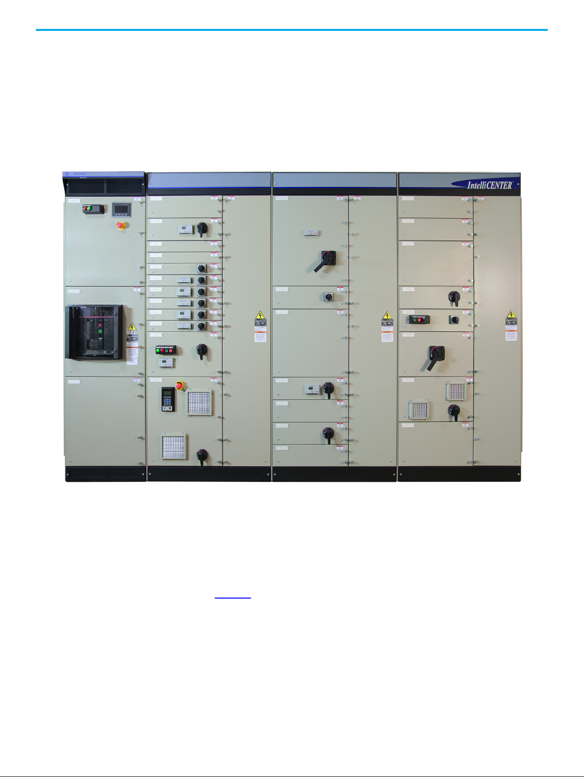
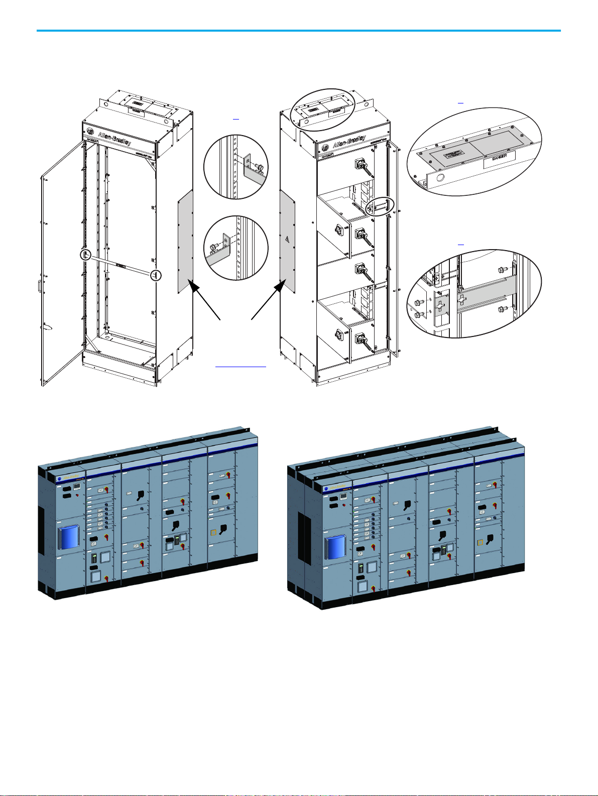
Structure CENTERLINE 2500 MCCs offer units with a full complement of AC drives, soft
starters, and other devices. Pluggable power connections on the back of the
unit plug into the vertical bus. A mechanical interlock helps prevent the unit
door from being opened while the main switch is in the ON/I position. An
additional mechanical interlock helps prevent the unit from being withdrawn
or inserted when the unit main switch is closed. Separate vertical wireways
isolate control and network cables from power wiring. Units are available as
fixed or withdrawable.
Figure 1 - CENTERLINE 2500 MCC
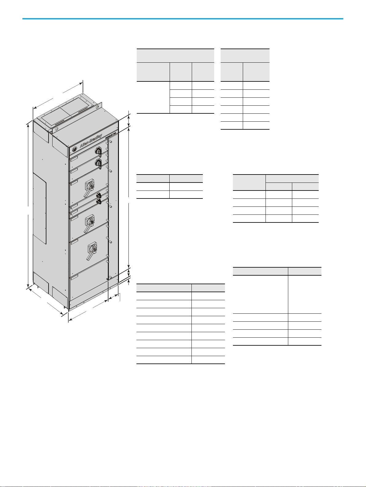
Dimensions
CENTERLINE 2500 MCCs columns are designed in widths between 500…1000
mm. Each column is 2300 mm high and either 600 mm or 800 mm deep.
Double front
in Figure 2
Unit size is described in terms of modules. Each module is approximately 80
mm high. Columns can accommodate 24 modules of different unit
combinations.
Rockwell Automation Publication 2500-IN001F-EN-P - April 2021 11
columns are also available. For additional options, see the tables
.
Page 12
Chapter 1 System Overview
Table 2 - Widths
Column
with Wireway
Column without
Wireway
Fixed or
Withdrawable
Unit Width
(1)
Vertical
Wireway
Width
(2)
Total
Column
Width
Fixed
Unit
Width
(3)
Total
Column
Width
500
200 700 500 500
300 800 600 600
400 900 700 700
500 1000 800 800
900 900
1000 1000
(1) Available from 1…24 modules.
(2) Recommended minimum wireway widths
for the various forms of separation:
• For 3B, 300 mm wide
• For 4B Type 5, 400 mm wide
• For 4B Type 7, 500 mm wide
(3) Applies to a full column (24 modules).
Table 3 - Depth
Single-front Double Front
600 1200
800
(1)
(1) S ingle-front IP42 configurations with
a 3200 A bus (air circuit breaker
units only) or 4000 A bus (all unit
types) require a 100 mm air gap
behind the column. In these
instances, the overall depth is 900
mm.
1600
(2)
(2) Double front IP42 configurations
with a 3200 A bus (air circuit
breaker units only) or 4000 A bus
(all unit types) require a 400 mm air
gap between the rear of the
columns. In these instances, the
overall depth is 2000 mm.
Table 4 - Thickness, Nominal
Description Measurement
Side plates (all depths) 2
Back plates (all widths) 2.5
Bottom mounting channel
(1)
(1) Front and rear.
3.5
Top plates (all widths) 2
Bottom plates 2
Horizontal wireway covers 2
Wireway doors 2
Doors
(2)
(2) 2 mm for 1…22 modules, 2.5 mm for 24 modules.
2, 2.5
ArcShield 480V doors
(3)
(3) 2.5 mm for 1…22 modules, 3 mm for 24 modules.
2.5, 3
Table 5 - Weight, kg
(1)
Column Depth
Column Width 600 mm 800 mm
600, 700 350 450
800 400 525
900 450 575
1000 500 650
(1) Weights that are shown are for an MCC column
with six units. Many factors (number of units,
horizontal power bus, wireway width, column
depth, and shipment packaging) affect the
actual weight. The packing slip shipped with an
MCC unit shows the exact shipping weights.
Table 6 - He ight
Dimension Measurement
Total unit height
• With top gland plate
• With ventilation hood
•With lift angle
• With lift angle on gland
plate
2300
2306
2370
2375
2387
Available unit height 1980
Top horizontal wireway 170
Bottom horizontal wireway 115
External mounting channel 35
All measurements are in mm unless
otherwise specified.
600 mm Deep Withdrawable Column
with a 200 mm Wireway Shown.
170
1980
35
1
1
5
500…1000
600 or 800
2300
200…500
500
Figure 2 - Typical Column Dimensions
12 Rockwell Automation Publication 2500-IN001F-EN-P - April 2021
Page 13
Chapter 1 System Overview
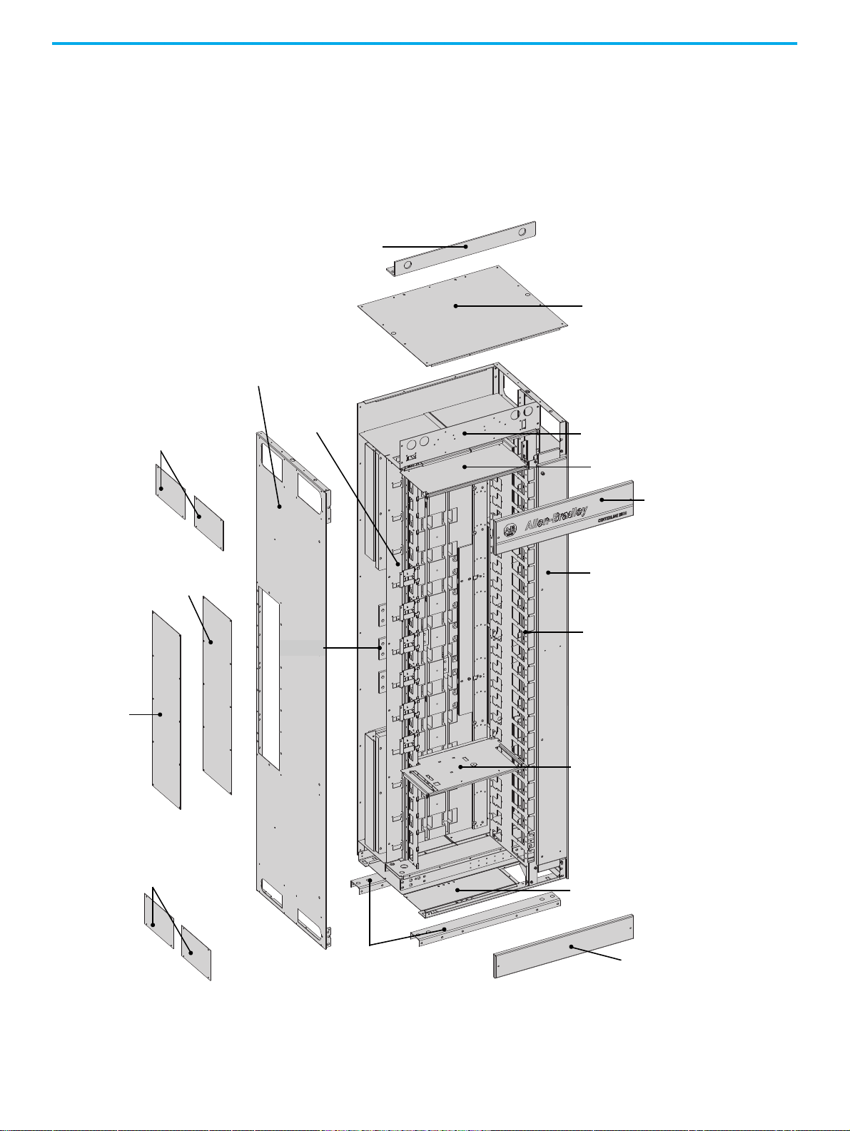
Lifting Angle
Network Wireway
Top Wireway
End Plates
Left Side Plate
Center End
Closing Plate
Bottom Wireway
End Plates
Mounting Channels
Bottom Plates
Bottom Wireway Cover
Right Unit Support and
Vertical Wireway Assembly
Vertical Wireway Door
Top Wireway Cover
Top Wireway Pan
Top Wireway Barrier
Top Plate
Optional ArcShield
Center End Closing
Plate Insulator
Horizontal
Power Bus
Single Unit
Support Pan
Typical Column Construction Columns are rigid, freestanding structures with heavy-duty, external
mounting channels. Columns are secured at the installation site by bolting
through clearance holes in the mounting channel or by welding.
The standard for internal sheet metal parts is Z275 galvanized metal for
Series D CENTERLINE 2500 motor control centers.
Figure 3 - Typical Column
Rockwell Automation Publication 2500-IN001F-EN-P - April 2021 13
Page 14
Chapter 1 System Overview
Door Latch Brackets
See page 49
for more information.
Pressure Relief Plate
See page 21
for more information.
Detail A
Detail B
Detail C
A
B
C
Detail D
D
Center End Closing
Plate with Insulator
Only on end-of-lineup
columns.
See Figure 3 on page 13
for more details.
Frame-mounted Brackets
See page 49
for more
information.
Columns Installed in a Single-front Configuration Columns Installed in a double front Configuration
NOTE: Double front IP42 configurations with a 3200 A bus (air circuit
breaker units only) or 4000 A bus (all unit types) require a 400 mm air
gap between the rear of the columns.
NOTE: Single-front IP42 configurations with a 3200 A bus (air circuit breaker units only)
or 4000 A bus (all unit types) require a 100 mm air gap behind the column.
Additional bracing is provided for ArcShield columns.
Figure 4 - ArcShield Column Protection Hardware
Figure 5 - Column Configuration
14 Rockwell Automation Publication 2500-IN001F-EN-P - April 2021
Page 15

Chapter 1 System Overview
Technical Data This table provides the technical specifications for the 2500 MCC.
The following certifications (2500-CT0xx) can be found at the Rockwell
Automation Literature Library: https://www.rockwellautomation.com/global/
literature-library/overview.page.
EN 60204-1:2006 + A1:2009 Safety of machinery – Electrical equipment of machines; Part 1: General requirements
IEC 61439-1 Low-voltage switchgear and controlgear assemblies; Part 1: General requirements
Standards
EC Directives
Certifications and
Markings
Rated Voltages
Rated Currents
Creepage Distances
and Clearances
Bus Material and
Plating
Degrees of
Protection
Forms of Separation IEC 61439-2 Forms 2b, 3b, 4b, or 4b Type 7
Column Dimensions Height, width, and depth See page 12
Units
Structural Surface
Treatments
Environment
(1) Up to 600 A top and bottom, effective 1200 A per column.
(2) The average temperature over a 24-hour period must not exceed 35 °C.
IEC 61439-2 Low-voltage switchgear and controlgear assemblies; Part 2: Power switchgear and controlgear assemblies
IEC/TR 61641 Ed. 3.0, 2014-1,
parts 1…7
Enclosed low-voltage switchgear and controlgear assemblies; Guide for testing under conditions of arcing due to
internal fault
2011/65/EU RoHS Directive
2004/108/EC EMC Directive
2006/95/EEC Low Voltage Directive
ABS and ABS shipboard 2500-CT015
, 2500-CT016, and 2500-CT017
CE Conformance Marked 2500-CT008 and 2500-CT009
China Compulsory Certificate (CCC) 2500-CT010, 2500-CT011, 2500-CT012, 2500-CT013, and 2500-CT022
DEKRA 2500-CT018, 2500-CT019, 2500-CT020, and 2500-CT021
EAC MCC-CT001
SII Approval 2500-CT014
Rated operating voltage, U
Rated frequency, f
Rated insulation voltage, U
e
n
i
Continuous current rating, I
Short circuit peak withstand, I
Short time withstand rating, I
e
pk
cw
Up to 690V, 3-phase
50…60 Hz
1000V, 3-phase
Horizontal bus up to 4000 A; vertical bus up to 1200 A per column
Horizontal bus up to 210 kA
Horizontal bus up to 100 kA for 1 second
(1)
Neutral (N) Full or half-rated
Rated impulse withstand voltage, U
imp
6 kV, 8 kV, or 12 kV
Material group (overvoltage category) IIIa (175 </= CTI < 400)
Pollution degree 3
Horizontal power bus Copper (optional tin plating)
Vertical distribution bus Copper with tin plating
Protective earth conductor (PE) Copper (optional tin plating)
IEC 60529 IP20, IP42, or IP54
Module size (approx) 80 mm high x 500 mm wide = 1 module
Modules per column, max 24 of varied unit combinations
Withdrawable unit sizes 1, 2, 4, 6, 8, 10, and 12 modules
Interior Z275 galvanized metal (painted interior available as custom option)
Exterior RAL 7032 Pebble Grey paint (additional colors available by request)
Storage temperature -25…+55 °C
Operating (ambient) temperature
-5…+40 °C
(2)
with up to 95% noncondensing humidity
Altitude Up to 1000 m without derating: derating over 1000 m
Rockwell Automation Publication 2500-IN001F-EN-P - April 2021 15
Page 16
Chapter 1 System Overview
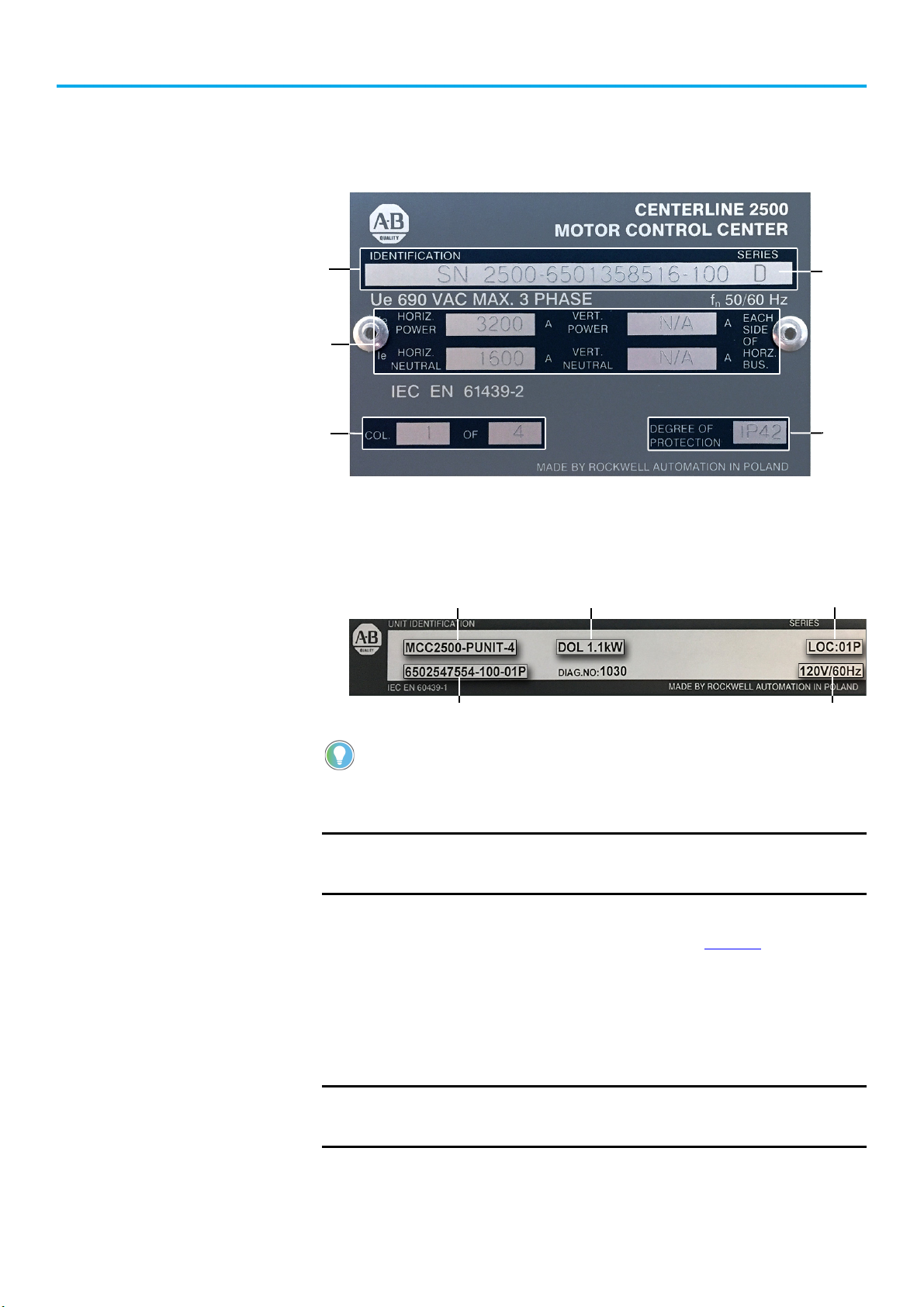
Catalog Number/Serial Number
Power Bus Voltage
and Current Rating
Enclosure
Type
Series
Letter
Identifies Column
Sequence Numbering
Catalog Number/Serial Number Unit LocationDevice Type and Rating
Voltage Rating
Order Number
Nameplate Data In compliance with EN 61439-1, each CENTERLINE 2500 MCC column is
supplied with a nameplate on the enclosure or vertical wireway door.
Figure 6 - Column Nameplate
Each unit also has an identification label. On withdrawable units, the unit
identification label is on the interior of the bottom plate of the unit. On fixed
units, the unit identification label is on the interior right side plate.
MCC Column-number Sequence
Figure 7 - Unit Identification Label
The catalog number or serial number and series letter are required to identify the
equipment properly to sales or factory personnel.
IMPORTANT
CENTERLINE 2500 MCCs are designed to function in any column-number
sequence. However, we recommend that columns be installed in
sequential order.
Each CENTERLINE 2500 MCC column nameplate identifies column-number
sequence, for example, MCC column 1 of 1 or 1 of 5. See Figure 6
for where to
find column-number sequence information.
Columns are numbered to match factory-supplied MCC elevation drawings
and to identify MCC columns and units easily. If there are questions about
column numbering during field installation, inspection, or operation, the
following instructions can provide guidance.
IMPORTANT
Leftmost column must be installed in the proper location for the bus to
splice. (Both ends of double-front MCCs must be installed as ends for
splicing.)
16 Rockwell Automation Publication 2500-IN001F-EN-P - April 2021
Page 17

Chapter 1 System Overview
The most important criteria for additions of columns to existing MCCs is
matching the horizontal bus, enclosure type, and network capabilities for the
complete MCC line up. The voltage, current rating, short circuit withstand,
and IP rating for all columns must be consistent.
ArcShield Labels MCC columns with arc proof assembly have a rating label (Detail E in Figure 8
on page 18) below the nameplate. There are also labels on other parts that must
be in place before operating an MCC with ArcShield; see Figure 8 on page 18
At the end of a lineup, CENTERLINE 2500 MCCs with ArcShield have a backcorner baffle and insulation on the center side closing-plate; see Figure 4 on
page 14 for more details. They also have external vertical support angles at each
end of the lineup.
.
Rockwell Automation Publication 2500-IN001F-EN-P - April 2021 17
Page 18
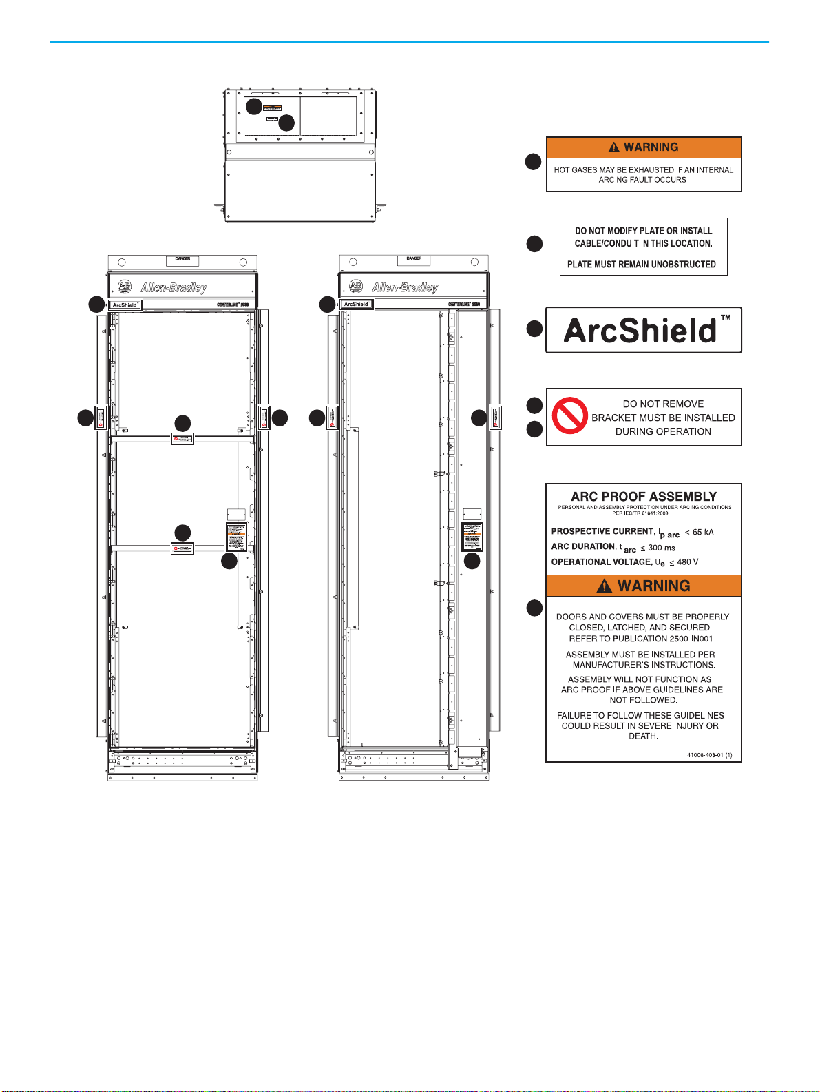
Chapter 1
C
E
A
B
Top View
Front View – Frame Mount Front View – Withdrawable
E
NOTE: All labels are external except for ‘E.’
A
B
C
D
F
C
DD
F
F
DD
E
Figure 8 - ArcShield Label Locations
18 Rockwell Automation Publication 2500-IN001F-EN-P - April 2021
Page 19

Chapter 2
Receiving, Handling, and Storage
See Receiving, Handling, and Storing CENTERLINE® 2500 Motor Control
Centers Instructions, publication 2500-IN002
This publication is shipped with each MCC, attached to the outside of the MCC
within the layer of clear polyethylene encasement (polywrap).
ATTENTION: MCCs are top and front heavy. To avoid personal injury or
structural damage, lift or move the MCC by only the methods that are outlined in
Receiving, Handling, and Storing CENTERLINE 2500 Motor Control Centers,
publication 2500-IN002
.
Receiving CENTERLINE 2500 MCCs are shipped upright as one or two column shipping
blocks or two or four double front column shipping blocks. Each CENTERLINE
2500 MCC shipping block is provided with a lifting angle. Each column in a
shipping block is bolted to the shipping skid with removable shipping angles
and covered with clear plastic wrap. Protection is for upright shipping and is
not waterproof or water-resistant. Equipment that extends from the
structures is also protected.
, for additional instructions.
Heavy-duty export packaging is similar to standard packaging, but uses a
polywrap suitable for occasional water spray. In addition, wood framing and
sheeting surround the columns. The heavy-duty export packaging is not
water-resistant, waterproof, or intended for long-term storage.
Upon delivery of the MCC, see the packing slip shipped with your MCC for
sizes and exact shipping weights. Inspect the shipment for lost or damaged
items. If lost or damaged items are detected, see the steps that are described in
publication 2500-IN002
.
Handling The following are acceptable methods of handling MCC columns within the
receiving facility. These methods are described in publication 2500-IN002
• Use of a forklift
• Overhead lifting (crane or hoist)
• Sling lifting
MCC columns must be handled in the upright vertical position. Failure to
comply with this method can lead to busbar, unit, and enclosure damage.
.
Rockwell Automation Publication 2500-IN001F-EN-P - April 2021 19
Page 20

Chapter 2
The MCC must remain bolted to the shipping skid until delivered to its final
installation area.
ATTENTION: MCCs are top and front heavy. To avoid personal injury or
structural damage, never attempt to lift or move the MCC by any means other
than the methods outlined in Receiving, Handling, and Storing CENTERLINE 2500
Motor Control Centers, publication 2500-IN002
.
Storage Store CENTERLINE 2500 MCCs, units, and related equipment in
environment with ambient temperatures ranging from -25…+55 °C
For short periods (less than 24 hours), temperatures of up to 70 °C (158 °F) are
allowed. Take care to help prevent damage from exposure to excessive
humidity, vibration, and shock.
Store MCCs with the plastic covering in place to help prevent dirt and dust
from entering the structure. Check periodically for condensation build-up and,
if necessary, install space heaters. To order space heaters,
Rockwell Automation representative
.
contact your
a clean, dry
(-13…+131 °F).
20 Rockwell Automation Publication 2500-IN001F-EN-P - April 2021
Page 21
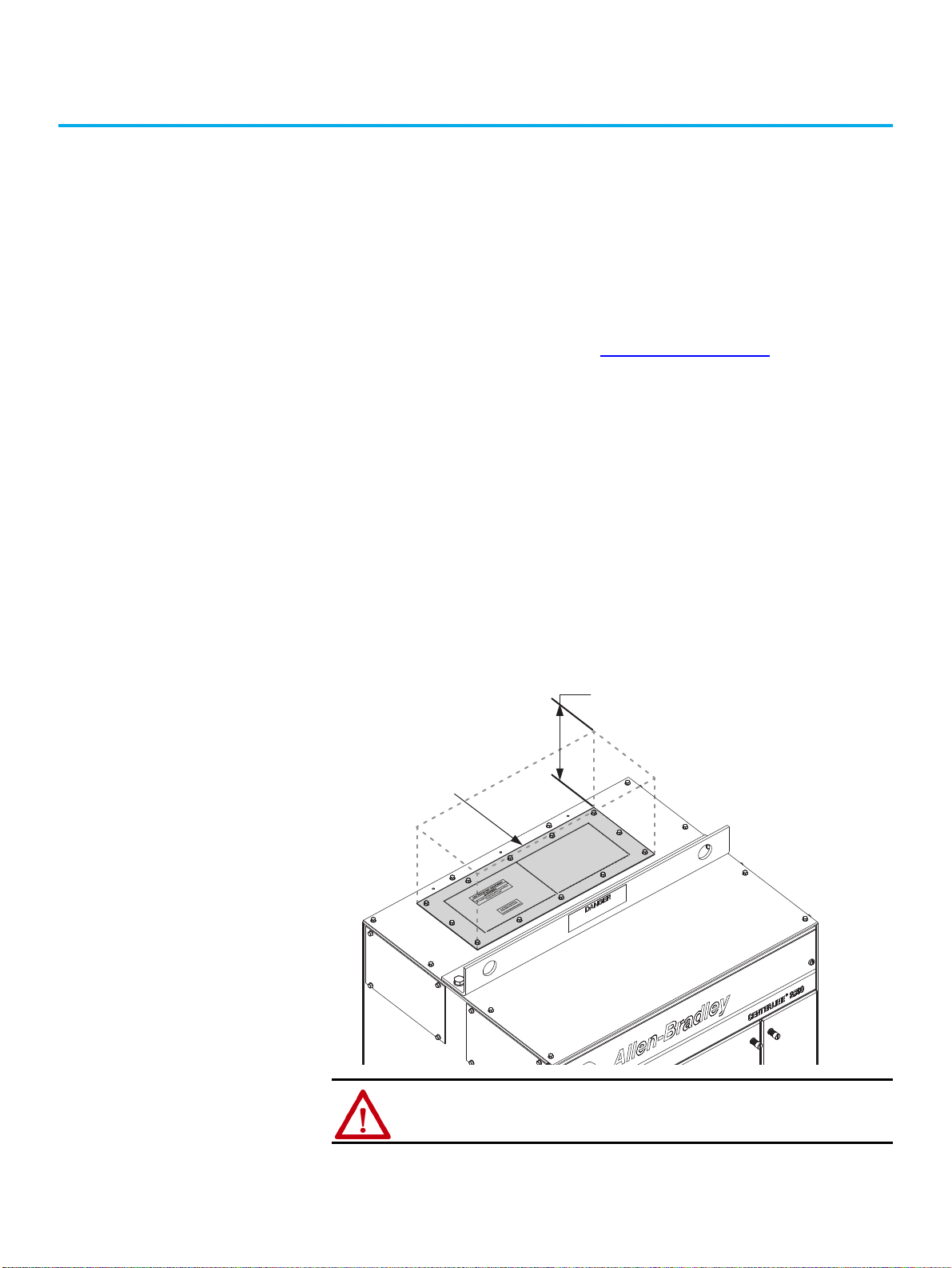
Chapter 3
300 mm
Minimum Clearance
ArcShield pressure relief
plate on top of column.
Install Columns
Location Planning When you plan the location for your CENTERLINE® 2500 MCC, consider the
following:
• Cable entry and exit points (see Appendix B on page 105
•Busways
• Overall height of installation area
• Alignment with other equipment
• Future needs
• Environment
The area must be level and the environment must be compatible with the
degree of protection that is provided by the enclosure.
)
ArcShield™ Clearance Space
Provide a minimum 300 mm of clearance space above the MCC to vent the
pressure relief plates if there is an arc flash.
ATTENTION: Do not step on the pressure relief plate, which can cause it not to
work properly during arc flash.
Rockwell Automation Publication 2500-IN001F-EN-P - April 2021 21
Page 22

Chapter 3 Install Columns
Environment
CENTERLINE 2500 MCCs are designed to operate under the service
conditions described in IEC 61439-1. Variations in temperature and relative
humidity can potentially cause occasional condensation.
Temperature
When you operate an MCC, ambient air temperature must remain in the range
of -5…+40 °C (23…104 °F). The average temperature over a 24-hour period must
not exceed 35 °C (95 °F).
Humidity
Noncondensing humidity is permissible up to 95% at the maximum
temperature of 40 °C (104 °F), with the average temperature not to exceed
(95 °F)
over a 24-hour period
.
Altitude
35 °C
The CENTERLINE 2500 MCC is designed to operate at installation sites at
altitudes up to 1000 m (3281 ft) above sea level without derating. If the altitude
at your installation site exceeds 1000 m (3281 ft) above sea level, contact your
Rockwell Automation® representative for derating information.
Pollution Degree
CENTERLINE 2500 MCCs are designed for use in a pollution degree 3
environment. IEC 61439-1 defines pollution degree 3 as, “conductive pollution
occurs or dry, non-conductive pollution occurs that become conductive due to
condensation.”
Remove Packing Materials When the MCC has been delivered to the site of installation, remove the
packaging material. Save any manuals and data sheets for future reference.
ATTENTION: To avoid personal injury, use caution when the motor control
center is not secured. Motor control centers are top and front heavy.
22 Rockwell Automation Publication 2500-IN001F-EN-P - April 2021
Page 23
Chapter 3 Install Columns
Shipping Angle
(four places)
Packing Box Brackets
(four places)
Detail A
Detail B
B
A
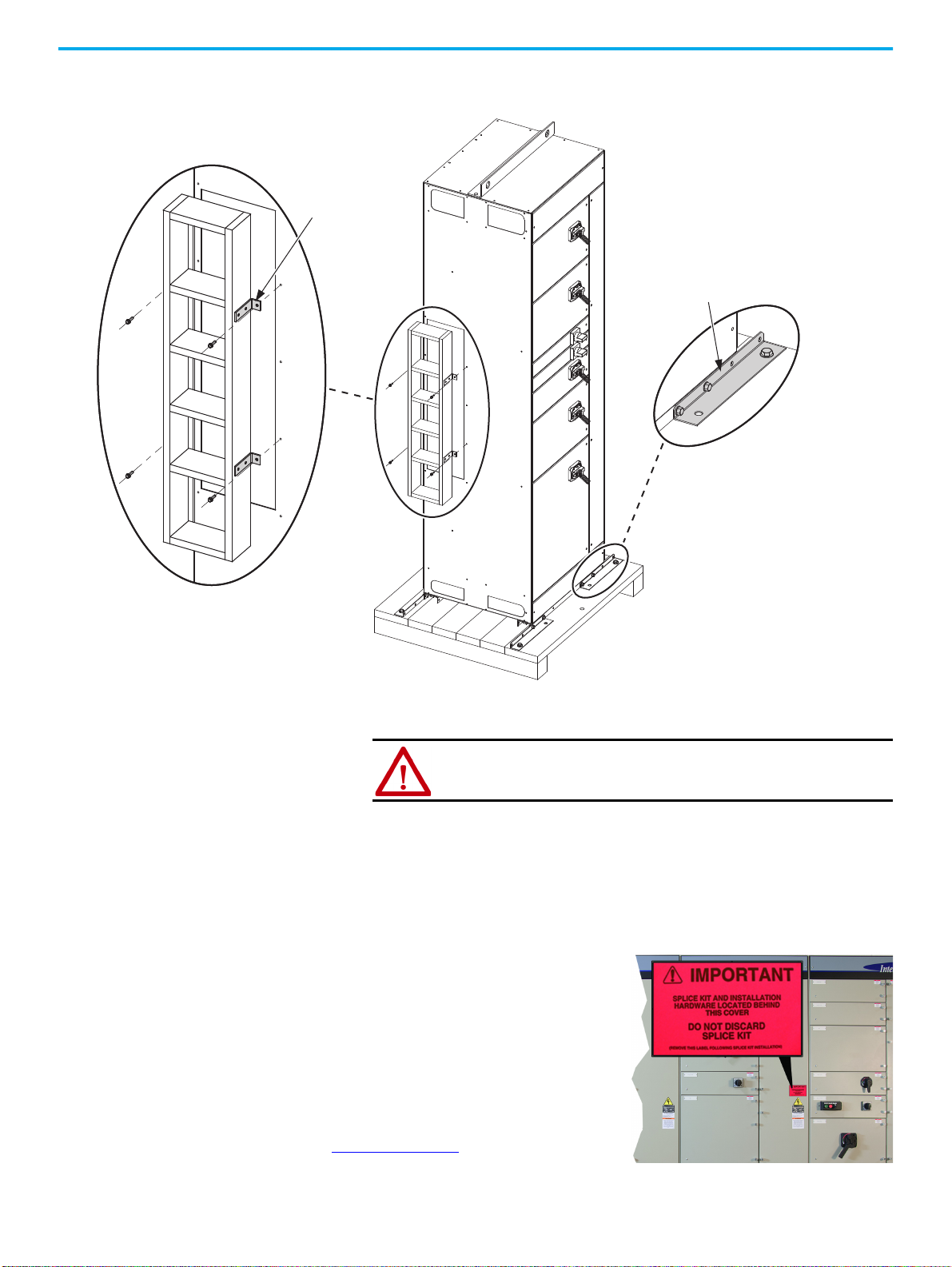
1. Remove the packing box around the horizontal bus if present and
remove the four brackets as shown (Detail A).
Locate Bus Splice Kits
A fluorescent pink, removable label (on
the outside of the column) designates
where provided power bus splice kits are
stored. PE splice kits are in the bottom
horizontal wireway, which is fastened to
the horizontal PE conductor.
Locate the splice kits and set aside for
later use. For the splice kit contents, see
Table 7 on page 41
2. Remove the bolts that secure each shipping angle (Detail B) from the
shipping skid.
ATTENTION:
Once the bolts are removed from the shipping angles, the
MCC is no longer secured on the skid.
3. Remove the shipping angles from the MCC.
You can now remove the MCC from the shipping skid.
.
Rockwell Automation Publication 2500-IN001F-EN-P - April 2021 23
Page 24
Chapter 3 Install Columns
T
o
p
E
n
d
C
l
o
s
i
n
g
P
l
a
t
e
s
B
o
tt
o
m
H
o
r
i
z
o
n
t
a
l
W
i
r
e
w
a
y
C
o
v
e
r
s
C
e
n
t
e
r
E
n
d
C
l
o
s
i
n
g
P
l
a
t
e
I
n
s
u
l
a
t
o
r
(
o
p
t
i
o
n
a
l
)
B
o
t
t
o
m
E
n
d
C
l
o
s
i
n
g
P
l
a
t
e
s
C
e
n
t
e
r
E
n
d
C
l
o
s
i
n
g
P
l
a
t
e
s
T
o
p
H
o
r
i
z
o
n
t
a
l
W
i
r
e
w
a
y
C
o
v
e
r
s
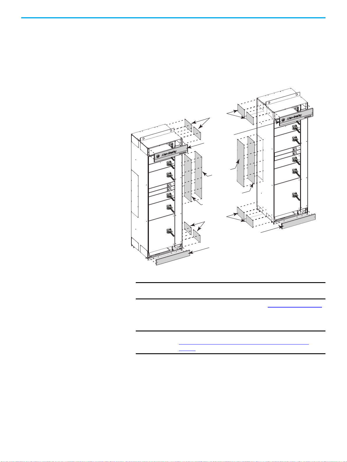
Removing the Covers
Follow these procedures for removing the covers on the MCC.
1. Remove the top and bottom horizontal wireway covers from the MCC.
2. If present, remove the top, bottom, and center end closing plates, on the
sides of the two columns that are to be joined.
Figure 9 - Wireway Covers and Closing Plates to Remove From the MCC
3. If ArcShield is present, remove the center end closing plate insulators.
IMPORTANT
When you plan MCC cable routing, consider cable replacement in
your plans.
For more information about cable installation, see Chapter 4 on page 49
4. For double front applications, remove the backplate of each MCC
column before you begin to position them.
IMPORTANT Save the M6 hardware removed from the backplate. It is used in
Join Back-to-back Columns in a Double Front Configuration
page 34.
24 Rockwell Automation Publication 2500-IN001F-EN-P - April 2021
.
on
Page 25
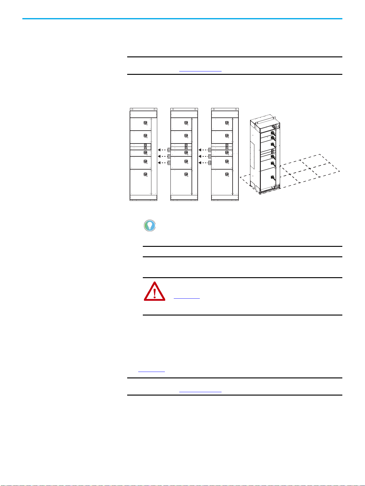
Position the Motor Control Center
The Horizontal Power Bus on Each Sequential
Column Extends Past the Column
Leftmost Column
Follow these procedures to position your MCC.
Chapter 3 Install Columns
IMPORTANT
Certain IP42 configurations require column air gaps. For more information,
see Figure 5 on page 14
.
1. Documentation packages that are shipped with assembled MCCs include
an MCC elevation drawing of a floor plan layout. Locate and use this floor
plan layout to position your MCC columns.
2. Identify the leftmost column.
The horizontal power bus does not extend past the leftmost MCC column. For
sequential columns, the horizontal power bus extends past the MCC.
Secure a Motor Control Center
3. Position the MCC in the location where it is to be installed.
IMPORTANT
The floor surface must be level.
4. Depending on the installation site, begin with the leftmost or right-most
column and install one shipping block at a time.
ATTENTION: For MCC handling guidelines, see Receiving, Handling, and
Storing CENTERLINE 2500 Motor Control Centers Instructions, publication
2500-IN002, which is provided with shipped MCC units. Use these
guidelines to help avoid personal injury and equipment damage during
handling, and to facilitate moving the MCC at the installation site.
Documentation packages that are shipped with assembled MCCs include an
MCC elevation drawing of a floor plan layout. To secure a column to the
foundation, see the provided floor plan layout and the following procedures.
See Chapter 4
IMPORTANT
for cable and conduit routing instructions.
Certain IP42 configurations require column air gaps. For more information,
see Figure 5 on page 14.
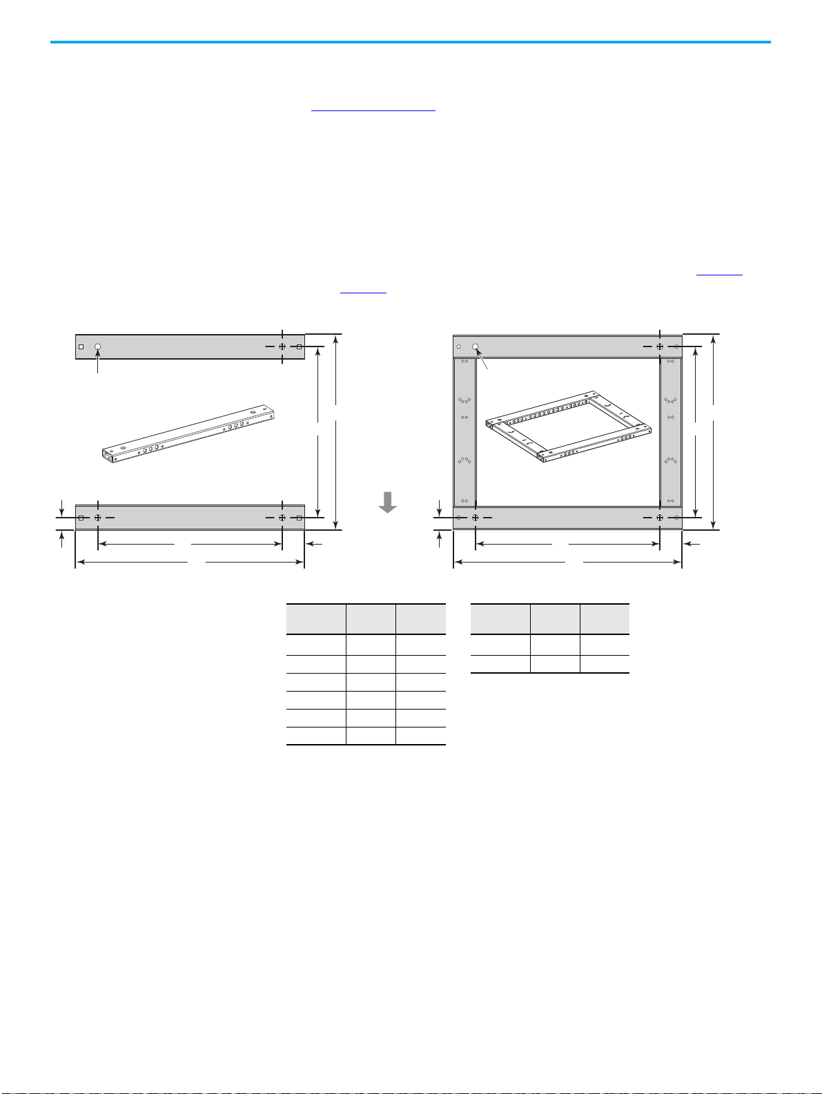
Securing Methods
MCC columns or shipping blocks can be bolted or welded to a foundation. Two
mounting channels on the bottom of each MCC column are used for either
securing method.
Rockwell Automation Publication 2500-IN001F-EN-P - April 2021 25
Page 26
Chapter 3 Install Columns
A
B
68
35
Mounting bolt holes (4),
18 mm dia.
Mounting bolt holes (4),
18 mm dia.
A
B
Front of Co lumn
C
D
C
D
68
35
Standard Mounting Channels (2 installed per column) Optional Mounting Frame (1 per column)
NOTE: Neither
mounting method is
flush with any side of
the MCC column.
Weld Down Method
See Figure 12 on page 32 to weld an MCC column or shipping block to a
foundation.
Bolt Down Method
Two mounting channels are provided for each MCC column. An optional
mounting frame is also available. Both mounting methods can be fastened
with up to four steel M12 bolts (minimum Property Class 8.8). For best results,
pre-locate and embed the bolts in the foundation before you install each MCC
column. For more information about mounting bolt locations, see page 27
through page 29
Figure 10 - Mounting Channel Dimensions and Bolt Locations
.
All dimensions are mm.
MCC Column
Width
(1)
500
600 461 597 800 712 782
700 561 697
800 661 797
900 761 897
1000 861 997
(1) Available only with the optional welded frame.
A B
361 497 600 512 582
MCC Column
Depth
C D
26 Rockwell Automation Publication 2500-IN001F-EN-P - April 2021
Page 27
Chapter 3 Install Columns
3 mm wide continuous bead of
caulk sealer around outside edge
of the sideplate being joined.
IMPORTANT: Do not allow ‘skin’
to form on the caulk before you
join the sections.
Seal IP54 Enclosures Before Connection
The following steps do not apply to IP20 and IP42 enclosures.
1. Remove the tube of caulk (mastic) sealer from the splice kit and read the
appl
ication directions on the tube.
2. Cut the nozzle at the first notch, 3 mm from the end.
3. Apply a continuous bead of caulk, 3 mm wide, around the outside edge
the sid
eplate of the fixed motor control center.
of
Slide the columns together.
4.
Verify that the ca
IMPORTANT
binets are level and joining holes are aligned.
If you removed the lifting angle from the IP54 enclosure, then you
must also seal the lifting angle bolt holes with the caulk sealer.
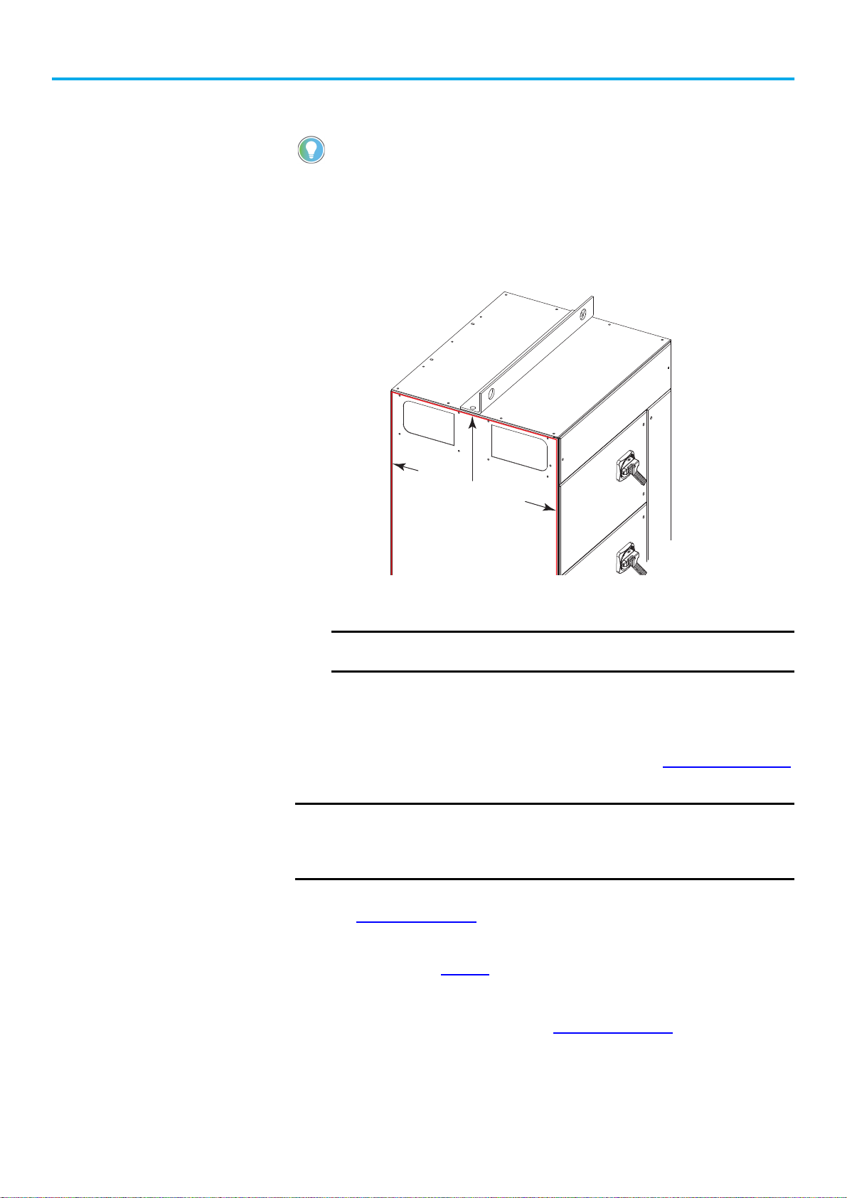
Secure Single Front, One Column-wide Shipping Blocks
The following instructions are to bolt down the MCC. See Figure 12 on page 32
for weld down requirements.
IMPORTANT
1. To locate the front mounting channel, remove the bottom wireway cover.
See Figure 3 on page 13
2. Secure the front of the MCC to the foundation with the mounti
dimensi
requirements on page
3. Reinstall the bottom wireway cover.
4.
To locate the rear mounting channel, remove the bottom wireway end
plate near the back of the
loc
ation.
Verify that there is adequate clearance on the sides of columns to access
the rear mounting bolt locations.
Use steel M12 bolts (minimum Property Class 8.8) to secure columns to the
foundation.
for cover location.
ng
ons in the following illustration and the mo
.
26
unit. See Figure 3 on page 13
unting channel
for end plate
Rockwell Automation Publication 2500-IN001F-EN-P - April 2021 27
Page 28
Chapter 3 Install Columns
500…1000
360…860
70
442…942
44
512…712
600…800
438…638
29
81
FRONT
REAR
Dimensions are in mm.
Diagram shows top view of 600 mm
and 800 mm column depths.
A
B
Protective earth
(PE) conductor
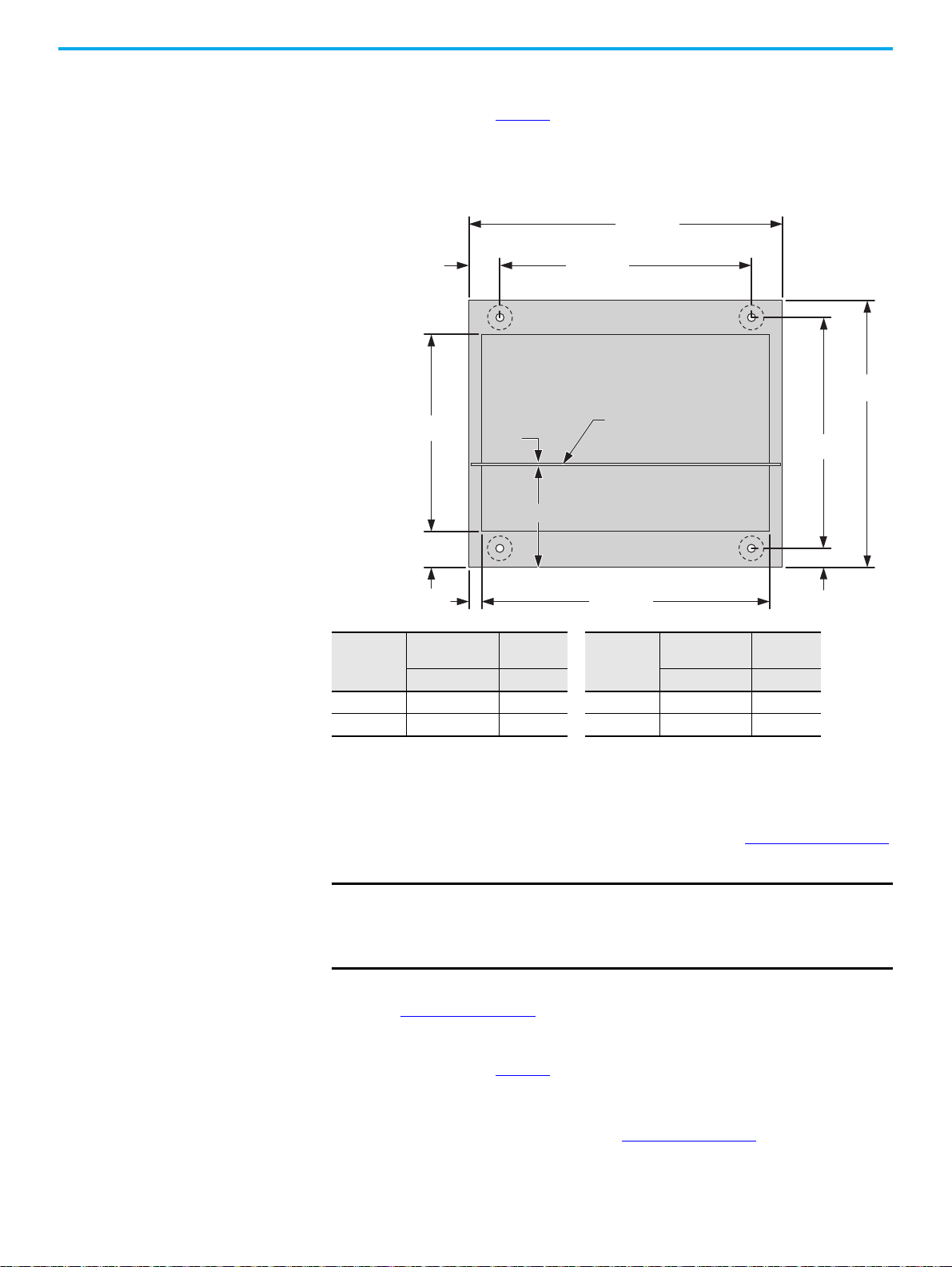
5. Secure the rear of the MCC to the foundation with the mounting
dimensions in the following illustration and the mounting channel
requirements on page 26
.
6. Reinstall the bottom wireway end plate.
Input Power,
A
Up to 1600 6 234 3200 18 222
2000…2500 12 228 4000 24 216
Material
Thickness, mm
A B A B
Distance,
mm
Input Power,
A
Material
Thickness, mm
Distance,
mm
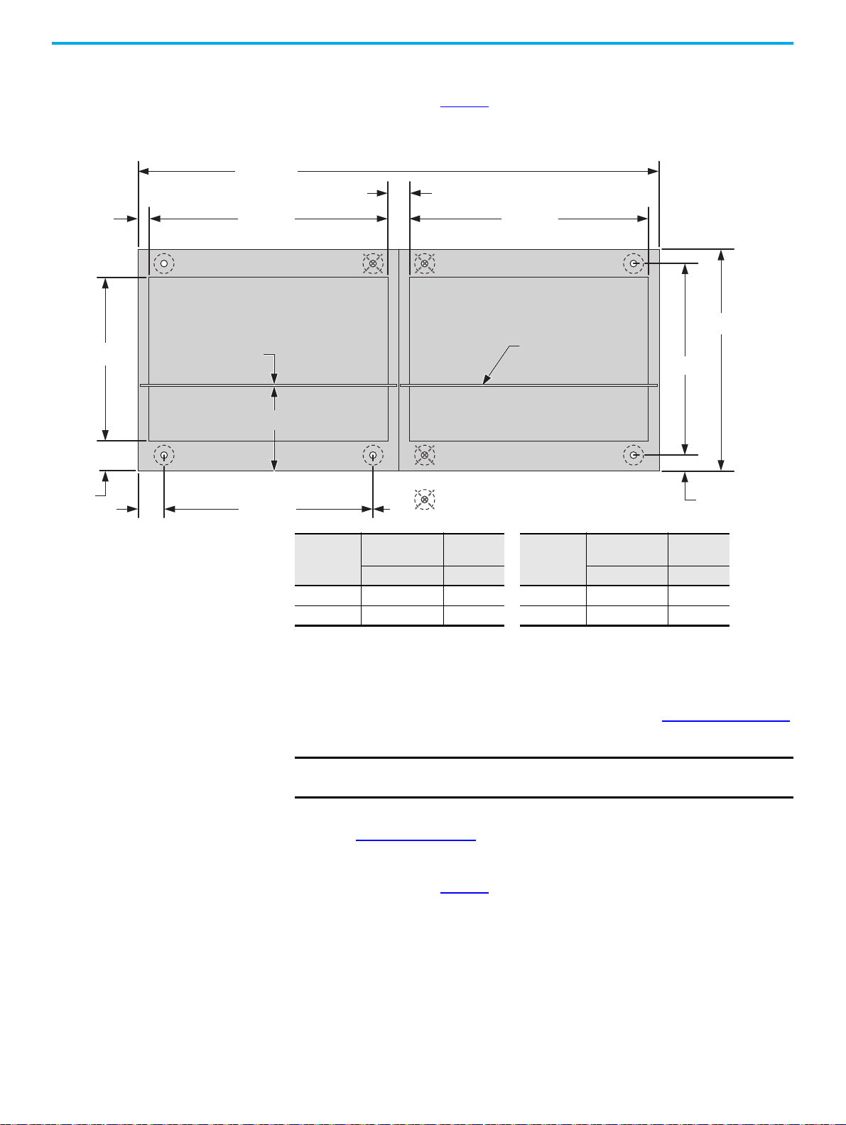
Secure Single Front, Two Column-wide Shipping Blocks
The following instructions are to bolt down the MCC. See Figure 12 on page 32
for weld down requirements.
IMPORTANT
Verify that there is adequate clearance on the exposed sides of columns to
access the rear mounting bolt locations.
Use steel M12 bolts (minimum Property Class 8.8) to secure columns to the
foundation. Not all bolt locations are used.
1. To locate the front mounting channel, remove the bottom wireway cover.
See Figure 3 on page 13
2. Secure the front of the MCC to the foundation with the mounting
for cover location.
dimensions in the following illustration and the mounting channel
requirements on page 26
3. Reinstall the bottom wireway cover.
.
4. To locate the rear mounting channel, remove the bottom wireway end
plate near the back of the unit. See Figure 3 on page 13
for end plate
location.
28 Rockwell Automation Publication 2500-IN001F-EN-P - April 2021
Page 29
Chapter 3 Install Columns
1000…2000
442…942
58
A
B
360…860
44
512…712
600…800
438…638
70
81
29
Protective earth
(PE) conductor
FRONT
REAR
442…942
First Column
= Mounting hole location not required.
Dimensions are in mm.
Diagram shows top
view of 600 mm and
800 mm column
depths.
5. Secure the rear of the MCC to the foundation with the mounting
dimensions in the following illustration and the mounting channel
requirements on page 26
.
6. Reinstall the bottom wireway end plate.
Input Power,
A
Up to 1600 6 234 3200 18 222
2000…2500 12 228 4000 24 216
Material
Thickness, mm
A B A B
Distance,
mm
Input Power,
A
Material
Thickness, mm
Distance,
mm
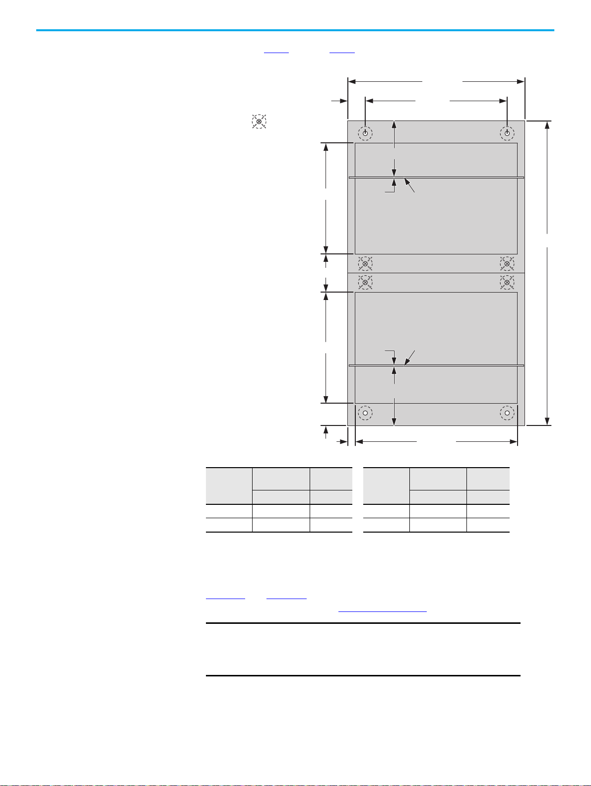
Secure Double Front, One Column-wide Shipping Blocks
The following instructions are to bolt down the MCC. See Figure 12 on page 32
for weld down requirements.
IMPORTANT
1. To locate the front mounting channel, remove the bottom wireway cover.
See Figure 3 on page 13
2. Secure the front of the MCC to the foundation according to the
dimensions in the following illustration and the mounting channel
requirements on page 26
3. Reinstall the bottom wireway cover.
Use steel M12 bolts (minimum Property Class 8.8) to secure columns to the
foundation. Not all bolt locations are used.
for cover location.
.
Rockwell Automation Publication 2500-IN001F-EN-P - April 2021 29
Page 30
Chapter 3 Install Columns
500…1000
360…860
70
A
B
442…942
1196
438…638
29
81
438…638
A
B
FRONT OF UNIT 2
FRONT OF UNIT 1
Protective Earth
(PE) Conductor
Protective Earth
(PE) Conductor
Dimensions are in mm.
Diagram shows top view of
600 mm column depths.
158
= Mounting hole location
not required.
4. Repeat step 1 through step 3 for the other side of the double front
shipping block.
Input Power,
A
Up to 1600 6 234 3200 18 222
2000…2500 12 228 4000 24 216
Material
Thickness, mm
A B A B
Secure Multiple Column-wide Shipping Blocks
Distance,
mm
Input Power,
A
Material
Thickness, mm
Distance,
mm
Figure 11 and Figure 12 are to bolt down a multiple-column shipping block. For
weld down requirements, see Figure 13 on page 33
IMPORTANT
Verify that there is adequate clearance on the exposed sides of
.
columns to access the rear mounting bolt locations.
Use steel M12 bolts (minimum Property Class 8.8) to secure columns
to the foundation. Not all bolt locations are used.
30 Rockwell Automation Publication 2500-IN001F-EN-P - April 2021
Page 31

Chapter 3 Install Columns
Fro nt
First Column Last ColumnSecond Column
Installation sequence, left to right.
Installation sequence, right to left.
First Column
Last Column
Additional Columns
Second ColumnAdditional Column
Fro nt
ATTENTION: The figure shows which bolts are required for
multiple-column shipping blocks. Drawings with specific
dimensions are supplied with each multiple-column shipping
block.
= Mounting hole locations not required.
Top View
Top View
Figure 11 - Bolt-down Requirements for Single Front, Multiple Column-wide Shipping Blocks
Rockwell Automation Publication 2500-IN001F-EN-P - April 2021 31
Page 32

Chapter 3 Install Columns
Front of Unit 1
Front of Unit 2
Installation sequence, left to right.
Installation sequence, right to left.
First Column Last ColumnSecond Column Additional Columns
First ColumnLast Column Second ColumnAdditional Columns
Front of Un it 1
Front of Un it 2
= Mounting hole locations not required.
Top View
Top View
ATTENTION: The figure shows which bolts are required for
multiple-column shipping blocks. Drawings with specific
dimensions are supplied with each multiple-column shipping
block.
Figure 12 - Bolt-down Requirements for Double Front, Multiple Column-wide Shipping Blocks
IMPORTANT
Use steel M12 bolts (minimum Property Class 8.8) to secure columns
to the foundation. Not all bolt locations are used.
32 Rockwell Automation Publication 2500-IN001F-EN-P - April 2021
Page 33

Figure 13 - Weld-down Requirements for Various Configurations
Fro nt
First Column Last ColumnSecond and Additional Columns
40 mm 40 mm
40 mm40 mm
40 mm40 mm
40 mm 40 mm
40 mm40 mm
40 mm40 mm
Welds
External
Mounting
Channel
First Column Last ColumnSecond and Additional Columns
40 mm 40 mm
40 mm40 mm
40 mm40 mm
40 mm
40 mm
40 mm40 mm
40 mm
40 mm
Weld
Weld
External
Mounting
Channel
Floor Line
Floor Line
Double Front Configurations
Single Front Configurations
Fro nt
Fro nt
Fro nt
Fro nt
Top View
Weld
Fro nt
End View
Top View
End View
Weld
Chapter 3 Install Columns
Rockwell Automation Publication 2500-IN001F-EN-P - April 2021 33
Page 34

Chapter 3 Install Columns
Mounting Strip
Top View
Join Columns
ATTENTION: Join columns is done after all columns/shipping blocks have
been secured to a foundation.
Do not use the hardware to draw columns together.
For double front applications, you must first join back-to-back columns before
you join the side columns.
Join Back-to-back Columns in a Double Front Configuration
1. Verify what holes are accessible and aligned between the two back-toback columns.
2. Starting with the leftmost column, use the M6 hex head cap screws that
you saved from removing the backplates to fasten the corresponding
back-to-back columns to each other.
3. Torque all M6 hex head cap screws to 5.6 N•m (50 lb•in.).
4. After all back-to-back columns are fastened to each other, install the
provided mounting strip and M5 taptite screws on the top of each joined
column set.
5. Torque the M5 taptite screws to 3.6 N•m (32 lb•in.).
6. After each back-to-back column has been joined, inspect and clean them
before closing. For the recommended procedures, see
step 20
on
page 82
.
34 Rockwell Automation Publication 2500-IN001F-EN-P - April 2021
Page 35

Chapter 3 Install Columns
89
336
353
336
353
744
547
573
165
Dimensions are in mm.
89
336
353
336
353
744
747
773
365
FRONT
FRONT
600 mm Deep Column 800 mm Deep Column
Step 1
Step 2
Step 1
Join Side Columns in Single Front and Double Front Applications
1. Starting with the first column, use M6 x 1.0 hardware that is provided in
the power bus splice kit to fasten the six joining holes together (step 1 in
the figure).
2. 800 mm deep columns: use a M6 hex head bolt, washer, and nut that is
provided in the power splice kit to fasten the two joining holes together
(step 2 in the figure).
3. Torque all fastened bolts to 5.6 N•m.
4. After side columns have been joined, inspect and clean them before
closing. For the recommended procedures, see
step 20
on
page 82
.
Rockwell Automation Publication 2500-IN001F-EN-P - April 2021 35
Page 36

Chapter 3 Install Columns
Seismic Capabilities Actual CENTERLINE 2500 MCC units have been seismically qualified by
dynamic (triaxial multi-frequency testing) seismic tests by using ICC–ES
(a)
AC156
seismic certification of electrical systems such as Motor Control Centers
(MCCs). The testing was conducted in accordance with ICC–ES AC156 criteria
and supports data for the following qualification requirements:
acceptance criterion that covers general equipment and supports the
• 2006 and 2009 International Building Code, International Code Council
• 1997 Uniform Building Code, Structural Engineering Design Provisions,
Zone 4
• ASCE Standards SEI/ASCE 7-05 and SEI/ASCE 7-10, Minimum Design
Loads for Buildings and Other Structures
The ICC–ES AC156 parameters for an S
DS level of 1.63 g at the roof level or below
is in the following table.
(1)
Test Criteria
ICC-ES-AC156 1.63 1.0 2.608 1.956 1.33 1.092 0.440 2.48 1.0
(1) Equipment is qualified for SDS and z/h values shown. Qualifications can be valid for higher SPS where z/h is less than 1.0.
SDS
(g)
z/h
(1)
Horizontal Ver tical
(1)
(1)
AFLEX
ARIG
AFLEX/ARIG
AFLEX
(1)
(1)
AFLEX/ARIG
ARIG
Rp/Ip
CENTERLINE 2500 MCC units demonstrated compliance with the following:
• 100% g level of Uniform Building Code 1997 (UBC) Zone 4
(the maximum UBC Zone)
• 100% g level of the International Building Code 2009 (IBC),
(SEI/ASCE: S
1.5 g @ 5 Hz and SD1 2 g @ 1 Hz) when subjected to a
DS
UBC Zone 4 earthquake or the IBC seismic event
Throughout the seismic testing, the MCC units were under power and
operated before, during, and after the seismic tests.
To obtain an IBC or UBC seismic withstandability, each individual CENTERLINE
2500 MCC lineup (including any in double-front applications) must be
mounted on an adequate seismic foundation. Installation must be conducted
per the anchoring requirements as indicated in this instruction manual. All
columns in the MCC lineup must also be bolted together per instructions in
Join Columns
on page 34.
In the CENTERLINE 2500 MCC lineup, mounting channels are incorporated
in the standard design. As an alternative to bolt down anchoring, these
mounting channels can be welded to an adequate seismic foundation. For
seismic weld down applications, see Figure 12 on page 32
Splice the Power Bus
ATTENTION: To help prevent severe injury or death, de-energize all power
sources to the MCC before you join and splice columns. Follow EN 50110
requirements, and local codes and guidelines.
IMPORTANT
(a) Acceptance Criteria for Seismic Cer tification by Shake-Table of Non-structural components (AC156), International Code of Council Evaluation
Service (ICC-ES), October 2010.
36 Rockwell Automation Publication 2500-IN001F-EN-P - April 2021
When you splice the horizontal power bus, always begin by splicing from the
lowest phase busbar and work from the bottom up.
.
Page 37

Chapter 3 Install Columns
21 3
IMPORTANT
NO-OX-ID Use– Do not get any busbar corrosion inhibitor on the bus splicing
hardware. It keeps the hardware from being properly torqued and damage
can occur.
Power bus consists of the main horizontal bus and neutral bus (if present).
Based on the current rating of the power bus, the splice kit contains the
appropriate splice bars and corresponding hardware. The following
procedures describe methods for splicing power buses that are based on the
ampere rating of the busbars.
For additional splicing information related to specific MCCs, see the elevation
drawing that is shipped with the MCC in the documentation package.
If necessary, remove units and unit support pans for the appropriate access to splice
the power bus.
Access the Power Bus
How to access the power bus depends on the column type. Follow the
procedures that are specific to your MCC columns.
For Columns with Main Units (see Figure 14, and Figure 15 on page 38)
1. Open the main unit door.
2. Depending on your unit, there are one or two splice covers with handles
to the side of the main, as shown in Figure 14
and Figure 15.
3. Remove the four M6 screws that secure each splice cover (step 1 in
Figure 14
4. For one splice cover, follow the removal sequence in Figure 14
For two splice covers, follow the removal sequence in Figure 15
, or steps 1 and 2 in Figure 15).
.
.
5. Reinstall all M6 screws.
The power busbars are now accessible.
Figure 14 - Remove Splice Cover on Main Unit (Frames 1 and 2) With Two Splice Covers
Rockwell Automation Publication 2500-IN001F-EN-P - April 2021 37
Page 38

Chapter 3 Install Columns
21
Figure 15 - Remove Splice Covers on Main Unit (Frame 4) With One Splice Cover
For Withdrawable Unit Columns with Vertical Wireways (see Figure 16 on page 39)
1. Open the vertical wireway door.
2. Locate and loosen the four M6 screws that secure the secondary splice
cover, as shown in step 1 of Figure 16
3. Slide the secondary splice cover so the four loosened screws align with
the entry hole of each keyhole slot, as shown in step 2 of Figure 16
4. Remove the secondary splice cover.
5. Locate the M6 screws for the primary splice cover, as shown in step 3 of
Figure 16
.
For vertical wireways up to 300 mm wide, there are only two screws with
keyhole slots that secure the primary splice cover.
For vertical wireways wider than 300 mm, there are four screws that secure
the primary splice cover. The two additional screws must be removed before
you can remove the primary splice cover.
.
.
6. Slide the primary splice cover so the two loosened screws align with the
entry hole of each keyhole slot, as shown in step 4 of Figure 16
.
7. Remove the primary splice cover.
38 Rockwell Automation Publication 2500-IN001F-EN-P - April 2021
Page 39

Chapter 3 Install Columns
NOTE: Gray arrows represent bolts only on
vertical wireways wider than 300 mm.
21 3
4
You can temporarily store the two splice covers at
the bottom of the vertical wireway.
8. Reinstall any removed screws for the primary splice cover.
You can temporarily store the two splice covers in the bottom of the vertical
wireway, as shown in Figure 16
.
The power busbars are now accessible.
Figure 16 - Remove Splice Covers on Withdrawable Units With Air Circuit Breaker (ACB) and Vertical
Wireways
For Withdrawable Unit Columns with Type 4b Vertical Wireways (see Figure 17 on page 40)
1. Open the vertical wireway door.
2. Locate and loosen the three M6 screws that secure the top splice cover, as
shown in step 1 of Figure 17
3. Remove the top splice cover.
You can temporarily store the top splice cover in the top of the vertical
wireway, as shown in step 2 of Figure 17.
.
4. Locate the three M6 screws for the bottom splice cover, as shown in step 3
of Figure 17
Rockwell Automation Publication 2500-IN001F-EN-P - April 2021 39
.
Page 40

Chapter 3 Install Columns
2
1
3
4
2
4
5. Remove the bottom splice cover.
You can temporarily store the bottom splice cover in the bottom of the vertical
wireway, as shown in step 4 of Figure 17
.
6. Reinstall any removed screws for the two splice covers.
The power busbars are now accessible.
Figure 17 - Remove Splice Covers on Withdrawable Units With Type 4b Vertical Wireways
40 Rockwell Automation Publication 2500-IN001F-EN-P - April 2021
Page 41

Chapter 3 Install Columns
Splicing The Power Bus
Follow these procedures to splice the power bus.
1. Open the bus splice kit that you removed from the MCC as instructed in
Locate Bus Splice Kits
The bus splice kit contains the following hardware.
Table 7 - Splice Kit Hardware for IP20, IP42, and IP54 Enclosures
Item Description Total Quantity
M6 x 1 x 12 screw 6
Self-wrenching bolt 2
Split lock washer 2
M6 x 1 x 5.2 hex nut 2
Flat washer 4
Vinyl trim edge, fits 0.5 mm (0.188 in.) 1.5 m (5 ft.)
Silicon adhesive sealant
(1) Supplied with only IP54 splice kits.
2. Assemble splice bars and hardware. Depending on our configuration,
see, Figure 18 on page 42
Repeat for each phase of busbar and, if present, the neutral bar.
(1)
on page 23.
1
or Figure 20 on page 44.
3. Tighten hardware to torque specifications.
See Torque Requirements for Hardware Connections on page 48
IMPORTANT
Do not grease or lubricate hardware.
.
4. Reinstall the splice covers and check that the bolts and nuts are secure.
5. Reinstall the units and unit support pans in their respective stations if
they were removed.
Rockwell Automation Publication 2500-IN001F-EN-P - April 2021 41
Page 42

Chapter 3 Install Columns
Frame 1 - 800 A and 1250 A
2 hole, RT
Frame 1 - 800 A and 1250 A
2 hole, LT
Frame 1 - 800 A and 1250 A
4 hole, LT and RT
Frame 1 - 1600 A
4 hole, LT and RT
Frames 1 and 2 - 2500 A
4 hole, LT and RT
Frame 2 - 2000 A
4 hole, RT
Frame 1 - 2000 A
4 hole, LT and RT
= Front of Unit RT = Right side of ACB column LT = Left side of ACB column
Frame 2 - 800 A and 1250 A
2 hole, RT
Frame 2 - 800 A and 1250 A
2 hole, LT
Frame 2 - 800 A and 1250 A
4 hole, LT
Frame 2 - 800 A and 1250 A
4 hole, RT
Frame 2 - 1600 A and 2000 A
4 hole, LT
Frame 2 - 1600 A
4 hole, RT
Figure 18 - Power Bus Splicing Configurations With Straight Splice Bars
IMPORTANT
Only for units with air circuit breaker (ACB). For other units, see page 46.
42 Rockwell Automation Publication 2500-IN001F-EN-P - April 2021
Page 43

Chapter 3 Install Columns
Frame 4 - 2000 A and 2500 A
4 hole, RT
Frame 4 - 2000 A and 2500 A
4 hole, LT
= Front of Unit RT = Right side of ACB column LT = Left side of ACB column
Frames 1, 2, and 4 - 3200 A
4 hole, LT and RT
Frames 1, 2, and 4 - 4000 A
4 hole, LT and RT
Figure 19 - Power Bus Splicing Configurations With Straight Splice Bars (continued)
IMPORTANT
Only for units with ACB. For other units, see page 46.
Rockwell Automation Publication 2500-IN001F-EN-P - April 2021 43
Page 44

Chapter 3 Install Columns
Frame 1 - 800 A and 1250 A
2 hole, LT
Frame 1 - 800 A and 1250 A
2 hole, RT
Frame 1 - 800 A and 1250 A
4 hole, RT
Frame 1 - 800 A and 1250 A
4 hole, LT
= Front of Unit RT = Right side of ACB column LT = Left side of ACB column
Frame 1 - 2000 A and 2500 A
4 hole, RT
Frame 1 - 1600 A…2500 A
4 hole, LT
Frame 1 - 1600 A
4 hole, RT
Frame 2 - 2000 A
4 hole, RT
Frame 2 - 800 A and 1250 A
4 hole, RT
Frame 2 - 1600 A and 2000 A
4 hole, LT
Frame 2 - 1600 A
4 hole, RT
Frame 2 - 800 A and 1250 A
2 hole, LT
Frame 2 - 800 A and 1250 A
2 hole, RT
Frame 2 - 800 A and 1250 A
4 hole, LT
IMPORTANT:
Crowfoot socket
wrenches are
recommended
for these splice bars.
Figure 20 - Power Bus Splicing Configurations With Z-splice Bars
IMPORTANT
Only for units with ACB. For other units, see page 46.
Crow foot wrenches are recommended to assemble these splice bars.
44 Rockwell Automation Publication 2500-IN001F-EN-P - April 2021
Page 45

Figure 21 - Power Bus Splicing Configurations With Z-splice Bars (continued)
Frame 2 - 2500 A
4 hole, LT
Frame 2 - 2500 A
4 hole, RT
= Front of Unit RT = Right side of ACB column LT = Left side of ACB column Z = Verify that this hole on the Z link plate is towards the back of the MCC unit.
Frame 4 - 2000 A and 2500 A
4 hole, LT
Frames 1, 2, and 4 - 3200 A
4 hole, LT
Use this hole to align
the Z link plate.
Frames 1, 2, and 4 - 4000 A
4 hole, LT
Frames 2 and 4 - 4000 A
4 hole, RT
Frame 1 - 4000 A
4 hole, RT
Frame 4 - 2000 A and 2500 A
4 hole, RT
Frames 2 and 4 - 3200 A
4 hole, RT
Frame 1 - 3200 A
4 hole, RT
IMPORTANT:
Crowfoot socket
wrenches are
recommended
for these splice bars.
Z
Z
Z
Z
Z
Z
Z
Z
Z
Z
Chapter 3 Install Columns
IMPORTANT
Only for units with ACB. For other units, see page 46.
Crow foot wrenches are recommended to assemble these splice bars.
Rockwell Automation Publication 2500-IN001F-EN-P - April 2021 45
Page 46

Chapter 3 Install Columns
All Frames - 800 A and 1250 A
2 hole
All Frames - 800 A and 1250 A
4 hole
All Frames - 1600…2500 A
4 hole
All Frames - 3200 A
4 hole
All Frames - 4000 A
4 hole
= Front of Unit
Figure 22 - Power Bus Splicing Configurations With Straight Splice Bars
IMPORTANT
Not for units with ACB. For those units, see page 42.
Splice the Protective Earth (PE) Conductor
The PE conductor is in the bottom horizontal wireway of an MCC column. Up
to four PE conductors can be present. To access the PE conductor, remove the
bottom horizontal wireway cover.
Follow these procedures to splice the Protective Earth Conductor.
1. Locate the PE splice bars.
46 Rockwell Automation Publication 2500-IN001F-EN-P - April 2021
Page 47

Chapter 3 Install Columns
Splice bars
as shipped.
PE splice bars
PE splice bars are secured to the end of the horizontal PE during
shipping.
2. Use the PE splice bars to join the horizontal PE of each column and
assemble the splice bars and hardware as shown.
3. Tighten hardware to torque specifications. See Torque Specifications
on
page 48.
IMPORTANT
Do not grease or lubricate hardware.
4. Reinstall the horizontal wireway cover and check that the bolts are
secure.
Control and Network Cables
After you finish joining and splicing columns, make sure to connect network
and other control cables as necessary.
See Appendix B on page 105
configurations.
See Chapter 9 on page 89
Rockwell Automation Publication 2500-IN001F-EN-P - April 2021 47
for the cable entry and exit points of various unit
for IntelliCENTER® options.
Page 48

Chapter 3 Install Columns
Example of an information label on the interior right side plate
of a fixed unit.
Example of an information label inside a vertical
wireway door.
Torque Specifications Tighten bus splice connections with a torque wrench according to the table.
Torque values can be found on the information label inside a vertical wireway
door or on the interior right side plate of fixed units.
Hardware Description Hardware Size Torque
Incoming line lug attachment bolts M12 x 1.75 61 N•m
Horizontal power bus to vertical distribution bus connection
(1)
M10 x 1.5 38 N•m
Horizontal power bus splice connection M10 x 1.5 38 N•m
Protective earth conductor (PE) splice connection M6 x 1.0 7.3 N•m
Column joining hardware M6 x 1.0 6.2 N•m
DeviceNet splice cable screws — 0.55 N•m
I/O terminal blocks — 0.45 N•m
(1) The factory-made power bus connections are tightened by a computer-controlled torquing system.
The following connections do not need to be retorqued:
• Vertical to horizontal bus connections
• Power conductor to horizontal bus connections
These factory-made connections do not require servicing for the life of the MCC.
48 Rockwell Automation Publication 2500-IN001F-EN-P - April 2021
Page 49

Chapter 4
Install Cable
When you install cable, verify that it is installed according to appropriate codes
and standards. Multi-conductor cables, cable trays, cable ducts, and conduit
are all acceptable methods of routing cable to your MCC.
Install ArcShield Protection After Wiring
IMPORTANT
Inside the MCC enclosure, route cable away from the PE conductor to avoid
damage. Position cable so bends are minimized and relative vertical alignment
to incoming connections is maintained. Final cable connections must not
place any additional strain on the termination blocks.
See the documentation package shipped with your MCC for the following
information:
• Approximate cable entry locations
• Space availability for incoming cables
• PE conductor locations
• Wiring schemes for main fusible disconnects, main circuit breakers, and
incoming line compartments
Install cable per supplied instructions. Size cable to appropriate codes and
standards.
You can temporarily remove ArcShield™ latch brackets to maker it easier to connect
load cables.
Consider removing a unit if you cannot access the screw on the left side of the
bracket.
All installed cable is installed must be compatible with the enclosure rating
of the MCC. Cable entry and exit points must be properly sealed so water
and moisture cannot enter or accumulate inside the enclosure.
Follow these procedures to install the door latch bracket/frame stiffener in the
wireway.
1. Open the door.
2. Install door latch bracket and frame stiffener bracket (if latter was
removed).
Verify that the latch bracket is in the correct orientation before you
install it. See Detail C in the following figure.
3. Torque all bracket screws to 3.6 N•m (32 lb•in).
Rockwell Automation Publication 2500-IN001F-EN-P - April 2021 49
Page 50

Chapter 4 Install Cable
Detail A
Frame Stiffener Bracket Wireway Latch Bracket
Detail
B
Detail C
A
B
C
Lugs
IMPORTANT
Verify that the compatibility of wire size, type, and stranding for the power
lugs is furnished. Use correct lugs in all applications. Crimp compression lugs
with manufacturer recommended tools.
IMPORTANT Use the MCC electrical schematics and wiring diagrams to verify field wiring
Incoming Line Lug Compartment
Top or bottom incoming line lug compartments are available. Base the lug
selection on the size, number, and type of conductor.
The following guidelines to select lugs are based on incoming line available
short circuit current, I
I
50,000 amperes RMS symmetrical use mechanical screw or
sc
crimp/compression type lugs.
> 50,000 amperes RMS symmetrical crimp/compression type lugs are
I
sc
recommended.
Install lugs so proper spacing is used between phases. Hardware must be
tightened per the torque specifications. For more information, see Torque
Specifications on page 48.
connection points.
The minimum cable size for customer wiring is 2.5 mm
.
sc
2
(14 AWG).
50 Rockwell Automation Publication 2500-IN001F-EN-P - April 2021
Page 51

Chapter 4 Install Cable
Main Disconnecting Means For information on incoming termination, see the documentation package
that is shipped with your MCC.
For main disconnects or circuit breakers, use the lugs provided.
Cable Bracing The CENTERLINE® 2500 MCC bus work system has been tested and is
qualified to withstand forces that exceed the short circuit withstand ratings
for the MCC. Incoming line cables and outgoing feeder cables must be
supported to withstand the same short circuit forces. Follow appropriate codes
and standards when bracing incoming and outgoing cables.
There are many sizes and types of cables, and different means by which the
cables can be supported. Cabling must be secured or braced for the weight of
the cable and if there is a fault.
IMPORTANT
Follow the guidelines addressed in IEC Standard 60364-5-52.
Position cable so bends are minimized and relative vertical alignment to
incoming connections is maintained. Final cable connections must not place
any additional strain on the termination blocks.
Secure Load Wires Standard internal separation within the MCC is IEC 61439-2 Form 3b. The
following IEC 61439-2 separation forms are also available as options.
• Form 4b Type 5: Terminals for external conductors are enclosed in a
metal or plastic frame within the vertical wireway. Terminals are
separated by insulated coverings.
• Form 4b Type 7: Terminals for external conductors are enclosed in
metallic partitions. The termination for each functional unit has its own
integral glanding facility.
Rockwell Automation Publication 2500-IN001F-EN-P - April 2021 51
Page 52

Chapter 4
Form 3 b Form 4 b Type 5
Form 4b Type 7
Support each wire as you install it so a strong connection is made. Do not
overtighten the screws to fasten the wires. Torque the screws to the values in
Table 9
Table 9 - Torque Values for Separation Forms
Cap Screw Size
M6 x 16 hex head socket 3.6 (32) 2.7…4 (24…35)
M8 x 20 hex head 5.6 (50) 4.2…7 (38…63)
IMPORTANT
.
N•m (Lb•in)
Targ et To rque Acceptable Torque Range
You can strip the holes if you over-torque the screws.
52 Rockwell Automation Publication 2500-IN001F-EN-P - April 2021
Page 53

Chapter 5
C
e
nt
e
r
o
f
H
a
nd
l
e
o
n
T
o
p
U
ni
t
2
0
0
0
m
m
,
m
a
x
F
l
o
o
r
L
i
ne
Door Latches, Operator Handles, and Unit
Interlocks
Height Considerations In accordance with EN 61439-1, operating devices (push buttons and handles)
must be no more than 2000 mm above floor level. If the MCC is mounted on an
elevated surface, the height from the floor to the center of the top handles must
be checked for compliance.
Figure 23 - Operator Handle Height
Rockwell Automation Publication 2500-IN001F-EN-P - April 2021 53
Page 54

Chapter 5 Door Latches, Operator Handles, and Unit Interlocks
Head Slot
Latch shown in vertical
(closed) position.
Door Latches There are two types of door latches available for the CENTERLINE® 2500 MCC:
quarter-turn door latches and ArcShield™ door latches.
Quarter-turn Door Latches
Latches are provided on each unit door to hold the door
closed and isolate the column. You can rotate the door
latches by using a standard slotted screwdriver in the head
slot.
Open the door latches as follows.
1. Rotate each door latch a quarter turn (90°) until its
head slot is horizontal.
2. Open the door once all latches are in the open position.
Close and lock the door latches as follows.
1. Close the door.
2. Use a slotted screwdriver to rotate each door latch a quarter turn (90°)
until all slots are vertical.
ArcShield Door Latches
The sleeved ArcShield door latches are
specialized spring-loaded latches.
They are designed to manage the
pressure generated during an arc
blast.
Follow the same procedures in the
Quarter-turn Door Latches
close a door with ArcShield door
latches.
IMPORTANT
ArcShield door latches are spring-loaded. When you close a door, push in
each latch as you turn it so it locks correctly for ArcShield protection.
to open or
Rotary-operator Handles Rotary-operator handles are available in three sizes for CENTERLINE 2500
MCCs. Because of their design and functionality, each size can require
different instructions to modify or to lock in different positions.
The following table details the different rotary-operator handle sizes.
54 Rockwell Automation Publication 2500-IN001F-EN-P - April 2021
Page 55

Table 10 -
Handle in ON/I Position Handle in TRIP/+ Position
Handle in OFF/O Position
Chapter 5 Door Latches, Operator Handles, and Unit Interlocks
Handle Size
Small
Medium
Large
(1) Handle pictures are not to scale.
(1)
Cat. No. Color
•140M-SB
•140M-SY
•140U-PB
•140U-PY
•140U-HM4
• 140U-HM4E
• Black
• Red/yellow
• Black
• Red/yellow
• Black
• Red/yellow
Small Rotary-operator Handles (Cat. Nos. 140M-SB and 140M-SY)
The following is a brief summary of operating instructions for small rotaryoperator handles. For additional information, see publication 140M-IN022
Figure 24 - Small Rotary-operator Handle Positions
Open the Unit Door
1. Turn the small rotary-operator handle to the OFF/O position.
2. Release the door latches.
3. Grasp the small rotary-operator handle and pull the unit door toward you
to open.
Close the Unit Door
.
1. Verify that the small rotary-operator handle is in the OFF/O position.
2. Close the unit door.
3. Secure the door latches.
Rockwell Automation Publication 2500-IN001F-EN-P - April 2021 55
Page 56

Chapter 5 Door Latches, Operator Handles, and Unit Interlocks
A
B
C
10°, max
3.5 mm
(0.14 in.), max
Open the Unit Door in the ON/I Position
When the unit door is closed and the small rotary-operator handle is in the
ON/I or TRIP/+ position, a defeater screw must be deliberately operated to
open the unit door.
1. Release the door latches.
2. Locate the defeater screw on the side of the small rotary-operator handle
near the OFF/O position (A).
3. Use a screwdriver to turn the defeater screw 10° (max) clockwise (B).
ATTENTION: Follow local codes and guidelines with requirements of EN 50110
when you work on energized equipment.
4. Carefully open the unit door (C).
Operator Handles for Circuit Breakers
If there is a circuit breaker fault, the circuit breaker operator handle moves to
the TRIP/+ position. Only reset the circuit breaker after the cause of the fault
has been determined and corrected.
Follow these procedures to reset the circuit breaker.
1. Turn the small rotary-operator handle to the OFF/O position.
2. After the fault has been corrected, verify that it is safe to re-energize the
unit and turn the small rotary-operator handle to the ON/I position.
Lock Units in the OFF/O Position
ATTENTION: Follow all company safety and lockout procedures, and local codes
when you perform this procedure.
56 Rockwell Automation Publication 2500-IN001F-EN-P - April 2021
Page 57

Chapter 5 Door Latches, Operator Handles, and Unit Interlocks
Follow these procedures to lock a unit in the
OFF/O position.
1. Turn the small rotary-operator handle
to the OFF/O position.
2. Push and hold the middle section of
the operator handle.
The lock opening is now visible.
3. Insert and secure the lock.
Up to three 8 mm (shackle diameter)
locks can be inserted.
Lock Units in the ON/I Position
Locking units in the ON/I position requires
user modification.
ATTENTION: Locking a small rotary-operator handle in the ON/I position can
conflict with local codes and emergency shutdown requirements.
To modify the operator handle so it remains locked in the ON/I position,
perform the following steps.
WARNING: To help prevent electrical shock, disconnect from the power source
before you modify any small rotary-operator handle.
1. Verify that the small rotary-operator handle to be modified is in the ON/I
position.
2. Release the door latches.
3. Open the door to access the locking nut that secures the small rotaryoperator handle to the door.
4. With the appropriate tool, remove the locking nut from the small rotaryoperator handle body (A in Figure 25 on page 58
).
5. Remove the small rotary-operator handle from the door (B).
6. Slide the provided defeater plug into the slot to prohibit access to the
defeater screw (C).
7. Reinstall the small rotary-operator handle into the door (D).
For proper installation, align the notch on the back of the small rotary-
operator handle with the corresponding slot in the door (E).
8. With the appropriate tool, reinstall the locking nut on the small rotaryoperator handle (F).
9. Torque the locking nut to 3.95 N•m (G).
10. Close the door.
11. Secure the door latches.
Rockwell Automation Publication 2500-IN001F-EN-P - April 2021 57
Page 58

Chapter 5 Door Latches, Operator Handles, and Unit Interlocks
3.95 N•m
(35 lb•in)
800T-N245
A
B
C
D
E
F
G
Figure 25 - Lock Small Rotary-operator Handles in the ON/I Position
Medium Rotary-operator Handles (Cat. Nos. 140U-PB and 140U-PY)
The following is a brief summary of operating instructions for medium
rotary-
Open the Unit Door
operator handles.
1. Turn the medium rotary-operator handle to the OFF/O position.
2. Release the door latches.
3. Grasp the medium rotary-operator handle and pull the unit door toward
you to open.
Close the Unit Door
1. Verify that the medium rotary-operator handle is in the OFF/O position.
2. Close the unit door.
3. Secure the door latches.
Lock Units in the OFF/O Position
ATTENTION: Follow all company safety and lockout procedures and local codes
when you perform this procedure.
Follow these procedures to lock a unit in the
OFF/O position.
1. The medium rotary-operator handle
must be in the OFF/O position.
2. Push and hold the middle section of the
operator handle.
The lock opening is now visible.
3. Insert and secure a lock.
Up to three 8 mm (shackle diameter)
locks can be inserted.
58 Rockwell Automation Publication 2500-IN001F-EN-P - April 2021
Page 59

Chapter 5 Door Latches, Operator Handles, and Unit Interlocks
A
B
C
10°, max
3.5 mm
(0.14 in.), max
Open the Unit Door in the ON/I Position
ATTENTION: Follow local codes and guidelines with requirements of EN 50110
when you work on energized equipment.
When the unit door is closed and the small rotary-operator handle is in the
ON/I or TRIP/+ position, a defeater screw must be deliberately operated to
open the unit door.
1. Release the door latches.
2. Locate the defeater screw on the side of the small rotary-operator handle
near the OFF/O position (A).
3. Use a screwdriver to turn the defeater screw 10° (max) clockwise (B).
4. Carefully open the unit door (C).
Lock Units in the ON/I Position
With medium rotary-operator handles, there are two ways to lock units in the
ON/I position. Both ways require user modification.
ATTENTION: Locking a medium rotary-operator handle in the ON/I position can
conflict with local codes and emergency shutdown requirements.
Rockwell Automation Publication 2500-IN001F-EN-P - April 2021 59
Page 60

Chapter 5 Door Latches, Operator Handles, and Unit Interlocks
To modify the operator handle so it remains locked in the ON/I position,
perform either of the following ways.
Lock the Unit in the ON/I Position With a Defeater Plug
1. Verify that the medium rotary-operator handle to be modified is in the
ON/I position.
2. Release the door latches.
3. Open the door to access the backside of the medium rotary-operator
handle.
4. With a screwdriver, remove the two screws that secure the medium
rotary-operator handle body to the door (A in Figure 26 on page 61
5. Remove the small rotary-operator handle from the door.
6. Slide the provided defeater plug into the defeater screw slot to help
prevent access to the defeater screw.
WARNING: To help prevent electrical shock, disconnect from the power source
before you modify any medium rotary-operator handle.
).
7. With the two screws that you previously removed, reinstall the medium
rotary-operator handle into the door (C in Figure 26 on page 61
).
8. Close the door.
60 Rockwell Automation Publication 2500-IN001F-EN-P - April 2021
Page 61

Chapter 5 Door Latches, Operator Handles, and Unit Interlocks
BA & C
1
1
2
2
D
Screw Hole
Screw
Hole
5…8 mm
(0.2…0.3 in.)
Lock the Unit in the ON/I Position With Locks
1. Verify that the medium rotary-operator handle to be modified is in the
ON/I position.
2. Release the door latches.
3. Open the door to access the backside of the medium rotary-operator
handle.
4. With a screwdriver, remove the two screws that secure the medium
rotary-operator handle body to the door (A in Figure 26
).
5. Remove the small rotary-operator handle from the door.
6. With the screwdriver, remove the two tabs (B in Figure 26
).
7. With the two screws that you previously removed, reinstall the medium
rotary-operator handle into the door (C in Figure 26
).
8. Close the door.
9. Push and hold the middle section of the operator handle.
The lock opening is now visible (1 in D of Figure 26
10. Insert and secure a lock (2 in D of Figure 26
).
).
Up to three 8 mm (shackle diameter) locks can be inserted.
Figure 26 - Lock Medium Rotary-operator Handles in the ON/I Position
Large Rotary-operator Handles (Cat. Nos. 140U-HM4 and 140U-HM4E)
The following is a brief summary of operating instructions for large
rotary-operator handles available for disconnects or circuit breakers.
For additional disconnect handle information, see publication 190-IN007
Rockwell Automation Publication 2500-IN001F-EN-P - April 2021 61
.
Page 62

Chapter 5 Door Latches, Operator Handles, and Unit Interlocks
Release Mechanism
Circuit Breaker Style
Disconnect Style
Release Mechanism
Figure 27 - Large Rotary-operator Handle Styles
Open the Unit Door
Follow these procedures to open the unit door.
1. Verify that the large rotaryoperator handle is in the OFF/O
position.
2. Release the door latches.
3. Hold the large rotary-operator
handle in the OFF/O position while
you push the release mechanism
down.
4. Carefully open the unit door.
Close the Unit Door
1. Verify that the large rotaryoperator handle is in the OFF/O
position.
2. Slowly close the door until contact with the large rotary-operator handle
is made.
3. Hold the large rotary-operator handle in the OFF/O position while you
close the door.
4. Close the door and secure the door latches.
Open the Unit Door in the ON/I Position
ATTENTION: Follow local codes and guidelines, and the requirements of
EN 50110 when you work on energized equipment.
When the unit door is closed and the large rotary-operator handle is in the
ON/I position, a defeater mechanism must be deliberately operated to open
the unit door (for example, to open the door of an energized unit).
62 Rockwell Automation Publication 2500-IN001F-EN-P - April 2021
Page 63

Chapter 5 Door Latches, Operator Handles, and Unit Interlocks
Defeater
Mechanism
Follow these procedures to open a door
with the large rotary-operator handle in
the ON/I position.
1. Release the door latches.
2. Locate the defeater mechanism on
the right side of the handle.
3. Use a screwdriver to push the
defeater mechanism in the
direction of the arrow.
4. Carefully open the unit door.
Operator Handles for Circuit Breakers
If there is a circuit breaker fault, the
circuit breaker operator handle moves to
the TRIP/+ position. Only reset the circuit breaker after the cause of the fault
has been determined and corrected.
Follow these procedures to reset the circuit
breaker.
1. Turn the circuit breaker handle from
the TRIP/+ position to the OFF/O
position.
2. Turn the circuit breaker handle from
the OFF/O position to the RESET
position.
3. Locate and correct the fault.
4. Verify that it is safe to re-energize the
unit.
5. Turn the handle from the RESET position to the ON/I position.
Lock Units in the OFF/O Position
ATTENTION: Follow all company safety and lockout procedures and local codes
when performing this procedure.
1. The large rotary-operator handle must be in the OFF/O position.
2. Pull the middle section of the operator handle toward you.
The lock opening is now visible.
3. Insert and secure the lock.
Up to three 8 mm (shackle diameter) locks can be inserted.
Rockwell Automation Publication 2500-IN001F-EN-P - April 2021 63
Page 64

Chapter 5 Door Latches, Operator Handles, and Unit Interlocks
Lock Units in the ON/I Position
Locking units in the ON/I position requires user modification.
1. Verify that the large rotary-operator handle to be modified is in the ON/I
position.
2. Release the door latches.
3. Open the door to access the backside of the large rotary-operator handle.
4. With a screwdriver, remove the four screws that secure the large rotaryoperator handle body to the door (A in Figure 28 on page 65
5. Remove the large rotary-operator handle from the door.
ATTENTION: Locking an operating handle in the ON/I position can conflict with
local codes and emergency shutdown requirements.
).
IMPORTANT
Place the four screws and the five O-rings aside so they can be
reinstalled.
6. With a sharp blade, cut the three stems that anchor the locking tab
(B in Figure 28 on page 65
).
7. With a long nose plier, remove the locking tab from the large rotaryoperator handle (C in Figure 28 on page 65
).
8. Reinstall the five O-rings in the appropriate locations on the backside of
the large rotary-handle (A in Figure 28 on page 65
).
9. With the flour screws that you previously removed, reinstall the large
rotary-operator handle into the door (D in Figure 28 on page 65
).
10. Close the door.
11. Push and hold the middle section of the operator handle.
The lock opening is now visible (1 in E of Figure 28 on page 65
12. Insert and secure an 8 mm lock (2 in E of Figure 28 on page 65
).
).
Up to three 8 mm (shackle diameter) locks can be inserted.
64 Rockwell Automation Publication 2500-IN001F-EN-P - April 2021
Page 65

B
1
1
2
2
3
C E
A & D
O-ring Locations
5…8 mm
(0.2…0.3 in.)
Chapter 5 Door Latches, Operator Handles, and Unit Interlocks
Figure 28 - Lock Large Rotary-operator Handles in the ON/I Position
Unit Interlocks
ATTENTION: Do not attempt to install or remove a unit while the unit main switch
is in the ON/I position.
A unit interlock is provided with each plug-in unit. Unit interlocks help
prevent units from being removed from or inserted into a column while the
operator handle is in the ON/I position.
Rockwell Automation Publication 2500-IN001F-EN-P - April 2021 65
Page 66

Chapter 5
Notes:
66 Rockwell Automation Publication 2500-IN001F-EN-P - April 2021
Page 67

Chapter 6
One Module, Withdrawable Unit Six Modules, Fixed Unit
Install and Remove Units
Unit Size Unit size is described in terms of modules. One module is 80 mm high by 500
mm wide. Withdrawable units are available in 1, 2, 4, 6, 8, 10, and 12 modules.
Fixed units are available in 2, 4, 6, 8, 10, 12, 14, and 16 modules.
Any unit size above one module must be in even increments. Therefore, you
cannot have a unit that is 11 modules high.
CENTERLINE® 2500 MCCs are available with many combinations of
withdrawable and fixed units.
Figure 29 - Unit Types
Withdrawable Units Units are available as either standard withdrawable or withdrawable with the
SecureConnect™ option.
On standard withdrawable units, the withdraw lever is located behind the unit
door, where you must first open the door to operate the lever. On withdrawable
units with SecureConnect, the withdraw lever is on the outside of the door, so
the unit lever can be operated and withdrawn while the door remains closed.
Additional features include a separate unit door and optional door-mounted
pilot devices. The unit door can be closed and latched, providing isolation
when the unit is removed. Pilot devices are housed in removable control
stations. An optional closing plate is available to help provide isolation if the
control station is removed.
Rockwell Automation Publication 2500-IN001F-EN-P - April 2021 67
Page 68

Chapter 6 Install and Remove Units
Interlock
Operator
Four Module U nit
Two and four module units have two latches on the right-hand side of the door
Unit Latch
(shown fully
disengaged)
Unit Latch
(shown fully
engaged)
Left-hand
(Hinged)
Side of Door
Withdraw Lever
Ten Module Unit
Six, eight, and ten module units have up to six latches
on the door, with two near the top of the door
Right-hand
Side of Door
Fully Engaged Latch
Partially Engaged Latch
Fully Disengaged Latch
Components of Withdrawable Units with SecureConnect
There are five main components on a withdrawable unit with SecureConnect
that distinguish it from the standard withdrawable unit; latches, withdraw
lever, interlock operator, and release tabs.
Figure 30 - Withdrawable Unit With SecureConnect Components
SecureConnect Unit Door Latches
On SecureConnect unit sizes of two and four modules, door
latches are on the right-hand side of the door; see Figure 30
On unit sizes of six, eight, and ten modules, there are up to
four door latches on the right-hand side of the door, and two
additional latches near the top of the door. For details on the
top door latches, see Figure 31 on page 69
The right-hand side latches have dual engagements:
• Full engagement, which is when the unit latch is
secured fully to the MCC structure and the
SecureConnect unit cannot be removed.
• Partial engagement, which is when the latch is released
from the MCC structure but remains secured to the
SecureConnect unit. In partial engagement, the
SecureConnect unit can be withdrawn from the MCC
structure while the door remains securely closed.
.
.
68 Rockwell Automation Publication 2500-IN001F-EN-P - April 2021
Page 69

Chapter 6 Install and Remove Units
Door Latch is Unlocked
Red color is visible on outside of door
Door Latch is Locked
Green color is visible on outside of door
A Retracted Withdraw Lever An Extended Withdraw Lever
Figure 31 - Top SecureConnect Door Latches on Withdrawable Unit Sizes of 6, 8, and 10 Modules
Withdraw Lever
The withdrawal lever is the large black handle in the lower center of each
SecureConnect unit. This handle can be retracted or extended, the latter
position to gain more mechanical leverage while operating the handle.
The withdraw lever has the same four positions on the standard or
SecureConnect withdrawable units. For more information on the positions,
see Operating Positions for All Withdrawable Units
on page 72.
Interlock Operator
The interlock operator is the small, black handle closest to the hinged side of
the unit door. To move a SecureConnect unit, the interlock operator must be
depressed during any withdraw lever movement. Depressing the interlock
operator releases the internal interlocks that help prevent any unwanted unit
movement.
Besides being depressed or released, the interlock operator can also be rotated
to the left (unlocked) or right (locked). The rotation direction controls the
internal interlocks and limits the positions that the SecureConnect unit can
move.
Rockwell Automation Publication 2500-IN001F-EN-P - April 2021 69
Page 70

Chapter 6 Install and Remove Units
The Interlock Operator Released
and in the Locked Position
The Interlock Operator Depressed to Rotate
from the Locked to the Unlocked Position
R
e
l
e
a
se
T
a
b
The interlock operator shaft includes a hole to insert a lockout/tagout lock for
additional safety.
Release Tabs
There are two release tabs inside the unit, one on each side of the unit and
behind the door; see Figure 32
when the SecureConnect unit is in the Released position to complete its
removal from the MCC structure.
. Both tabs must be depressed simultaneously
Figure 32 - Release Tab Inside the SecureConnect Unit
70 Rockwell Automation Publication 2500-IN001F-EN-P - April 2021
Page 71

Chapter 6 Install and Remove Units
PE
Unit
Load
Unit Line
Control
Network
Two or More Module Withdrawable Unit
Protective Earth
Conductor (PE)
ControlNetwork Unit Load
Connection
Unit Line
Connection
Customer Load
Connection
Isolated
Control and
Network
Wireway
PE
Network
Control
Guide Pins (2)
Line and
Load
One-module Withdrawable Unit
Network
Control
PE
Guide Pin
Guide Pin
Line and Load
Subplate Connections for One Module Withdrawable Units
Withdrawable Unit Connections
All withdrawable units have withdrawable line, load, control, network, and PE
connections. Outgoing load and control connections from these units are
made in the vertical wireway. All withdrawable units use a sliding track and a
mechanical lever for ease of insertion and removal.
Figure 33 - Connections for All Multiple-module Withdrawable Units
Rockwell Automation Publication 2500-IN001F-EN-P - April 2021 71
Figure 34 - Connections for a One-module Withdrawable Units
Page 72

Chapter 6 Install and Remove Units
Locking Mechanism
Withdraw Lever
Locking Mechanism
Squeezed and Held
Operating Positions for All Withdrawable Units
Standard and SecureConnect withdrawable units have four operating
positions: Connected, Test, Disconnected, and Released. Detents are present
to confirm that the unit is in one of the four positions. An interlock helps
prevent the unit from being inserted or removed while the branch circuit
device is in the ON/I position. Stabs are provided to make the line and load
connections. A first make, last break PE contact is also provided. Control and
network connections plug into an isolated vertical wireway on the left side of
the column. See the following descriptions for additional information about
the features of each position.
Icon Position Description
Connected
Test
Disconnected
Line, load, control, network, and PE connections are all engaged. Units can be locked in the
Connected position.
Control, network, and PE connections are engaged. Line and load connections are isolated. In
this position, you can verify control and network wiring, and unit functionality. Units can be
locked in the Test position.
An isolated position where the unit remains housed in the column and the PE connection is
engaged, but no other connections are present. Units can be locked in the Disconnected
position.
For Only Units with SecureConnect
Released
Release Tabs
Withdrawable units can be removed from the columns to isolate them from all connections.
Released units can be locked to help protect against insertion.
Withdrawable units with SecureConnect have a release tab on each side of the unit that must be
depressed simultaneously before the unit can be removed completely from the columns. See
Release Tabs
on page 70.
Select an Operating Position on a Standard Withdrawable Unit
1. Turn the rotary operator handle on the unit door to the OFF/O position.
2. With a screwdriver, turn each latch slot one-quarter turn.
3. Open the unit door to access the withdraw lever.
4. Grasp the withdraw lever with your right hand.
5. With the same hand, squeeze the locking mechanism towards the
withdraw lever.
When squeezed and held, the locking mechanism is unlocked and the
withdraw lever can be moved.
6. With the locking mechanism held in the unlocked position, rotate the
withdraw lever to the desired position.
Mechanical detents are used to confirm that a position is selected.
72 Rockwell Automation Publication 2500-IN001F-EN-P - April 2021
Page 73

Chapter 6 Install and Remove Units
Withdraw lever in Released position (and locked out).
Withdraw lever in Disconnected position (and locked out).
Withdraw lever in Test position (and locked out).
Withdraw lever in Connected position.
7. When you reach the desired position, release the locking mechanism to
lock the withdraw lever in that position.
Figure 35 - Various Positions for Standard Withdrawable Units
Select an Operating Position on a Withdrawable Unit With SecureConnect
To remove withdrawable units with SecureConnect, perform the following
steps.
1. Turn the rotary operator handle to the OFF/O position.
2. With a screwdriver, turn each SecureConnect latch slot one-quarter turn.
Each slot is then in the partial engagement position, which means the
latches are disconnected from the MCC structure while the door remains
attached to the SecureConnect unit.
In this latch position, the SecureConnect unit maintains its arc-resistant
rating.
IMPORTANT SecureConnect unit sizes between six and 10 modules have up to four
latches on the right-hand side of the door, and two near the top of the
door. For more information about these door latches, see page 68
3. With your left hand, depress the interlock operator and rotate it to the
left or right position for the following result.
If Then
To move the unit from Connected
to Test
To release or disconnect the unit Depress and rotate the interlock operator to the right (locked) position.
Depress and rotate the interlock operator to the left (unlocked) position.
.
Rockwell Automation Publication 2500-IN001F-EN-P - April 2021 73
Page 74

Chapter 6 Install and Remove Units
Four-module Blanking Door Shown
Interlock Operator in the Unlocked Position; Withdraw Lever in the Connected Position.
Interlock Operator in the Unlocked Position; Withdraw Lever in the Test Position.
Interlock Operator in the Locked Position; Withdraw Lever in the Disconnected Position.
Interlock Operator in the Locked Position; Withdraw Lever in the Released Position.
IMPORTANT Once you release the interlock operator, the withdraw lever is locked
in position and cannot be moved again until you depress the interlock
operator.
4. To disconnect or release the unit, depress the interlock operator with
your left hand while you move the withdraw lever through each of the
Test, Disconnect, and Release positions.
The interlock operator shaft includes a hole to insert a lockout/tagout lock for
additional safety in any position.
5. If the SecureConnect unit is in the Release position and you intend to
remove the SecureConnect unit from the MCC, then you must press the
release tabs on each side of the SecureConnect unit. See Release Tabs
page 70 for where these tabs are located.
For added safety, Rockwell
Automation recommends
that you purchase and install
blanking doors for whenever
a SecureConnect unit is
removed from the MCC.
on
Figure 36 - Various Positions of Withdrawal Units with SecureConnect
74 Rockwell Automation Publication 2500-IN001F-EN-P - April 2021
Page 75

Safety Guidelines
Bottom of unit support pan
Screw location
on left side
Screw locations
on right side
to Install and Remove
All Withdrawable Units
Chapter 6 Install and Remove Units
ATTENTION: De-energize, lock out, and tag out all sources of power to the MCC
when you install or remove MCC units. If MCC units are installed or removed with
power that is applied to the main power bus, follow established electrical safety
work practices. For further information, see the publication, NFPA 70E: Standard
for Electrical Safety in the Workplace®.
ATTENTION: If power sources are connected to the motor control center, use
extreme caution when you insert units. All busbars and the line sides of the
inserted units are energized and contact with these parts can cause injury or
death.
ATTENTION: To increase operator safety and help prevent equipment damage,
we recommend that two people install or remove units that are in the upper six
modules or over 1600 mm above floor level.
Units with door-mounted operator handles, switches, and disconnects must
be in the OFF/O position before units are inserted or removed.
Do not attempt to install or remove a unit when the unit main switch is in the
ON/I position.
Insert a Withdrawable Unit
IMPORTANT
The unit support pan below the unit compartment must be in place before
you install the unit.
Follow these procedures to insert a withdrawable unit.
1. Fully open the unit door and verify that the unit support pan has been
installed.
The unit support pan is secured with two screws on the right side and
one screw on the left side.
For one module units, verify that the subplate is installed. The subplate is
attached to the column with two mounting screws.
2. Rotate the unit withdraw lever to the Released position.
3. Slowly slide the unit into the column along the tracks on the unit support
pan until it locks in the Disconnected position.
Rockwell Automation Publication 2500-IN001F-EN-P - April 2021 75
Page 76

Chapter 6 Install and Remove Units
4. Slide the locking mechanism toward the withdraw lever, rotate the
withdraw lever to the Test position, and continue to insert the unit into
the column.
The unit locks in the Test position.
5. Slide the locking mechanism toward the withdraw lever again, and rotate
the withdraw lever to the Connected position.
Vertical bus shutters automatically opens as the unit is inserted.
6. Insert the unit until it locks in the Connected position.
The unit is now installed in the column.
7. Connect any door-mounted devices.
8. Close the unit door and secure the door latches.
Refer to
on page 72 for additional information on the withdraw lever.
Select an Operating Position on a Standard Withdrawable Unit
Remove a Withdrawable Unit 1. Fully open the unit door.
2. Unplug or remove door-mounted pilot devices.
3. Slide the locking mechanism on the withdraw lever to the left and rotate
the withdraw lever to the Test position.
4. Slide the locking mechanism toward the withdraw lever and rotate the
withdraw lever to the Disconnected position.
5. Slide the locking mechanism toward the withdraw lever again and rotate
the withdraw lever to the Released position.
Continue to slide the unit out of the column. The unit can now be
removed from the column.
Shutters close automatically as the unit is removed.
6. Close the unit door and secure the door latches.
Remove the Unit Door It is not necessary to remove the unit door to install or remove a unit from a
column. However, if a unit door must be removed, use one of the following
procedures.
If present, door-mounted control stations can be removed from the door and
kept with the unit.
Before you perform work on units or unit doors, verify that the unit main
switch is in the OFF/O position.
Multiple Module Unit Doors
Follow this procedure to remove multiple module unit doors.
1. Verify that the unit main switch is in the OFF/O position.
2. Release each door latch.
3. Fully open the unit door.
4. Remove or disconnect door-mounted devices and wiring.
5. Slide the hinge pins upward to remove.
6. Swing the door to near closed position and lift outward to remove.
7. To install the unit door, reverse this procedure.
76 Rockwell Automation Publication 2500-IN001F-EN-P - April 2021
Page 77

Chapter 6 Install and Remove Units
One Module Unit Doors
Follow this procedure to remove one module unit doors.
IMPORTANT
Remove the unit from the column before removing its door. Follow unit
removal procedures on page 76.
1. Verify that the unit main switch is in the OFF/O position.
2. Release each door latch.
3. Fully open the unit door.
4. If a control station is provided with a plug for control wires, unplug this
connection before removing the unit.
5. Remove or disconnect door-mounted devices and wiring.
6. Remove the two screws that fasten the hinge to the column.
7. Remove the unit door and hinge assembly from the column.
8. To install the unit door, reverse this procedure.
Rockwell Automation Publication 2500-IN001F-EN-P - April 2021 77
Page 78

Chapter 6 Install and Remove Units
Notes:
78 Rockwell Automation Publication 2500-IN001F-EN-P - April 2021
Page 79

Chapter 7
Commissioning
Introduction This chapter provides guidance for the startup of a newly installed MCC.
We recommend that you make an itemized list that includes the following:
• Serial number
• Number of columns
• Number of units and their corresponding voltage
• Current ratings
• Kilowatt ratings
• Types of circuits
• Fuse sizes
• Circuit breaker ratings and trip settings
• Other important data
Pre-commissioning Checklist
Save this itemized list in a file with other MCC data, such as component
manuals, MCC manuals, overload relay instructions, and wiring diagrams.
ATTENTION: Follow applicable company safety procedures.
ATTENTION:
energizing check
and locked in the OFF/O position. Follow EN 50110 requirements, and local codes
and guidelines.
Use a voltmeter to verify that the remote MCC power sources are disconnected.
ATTENTION: Power factor correction capacitors (PFCCs) must be applied
correctly. Temporarily disconnect PFCCs when they are connected to the motor
circuit, and the startup procedure requires the respective motors to be jogged,
inched, or bumped (rotation direction check).
For additional assistance, contact your Rockwell Automation representative.
ATTENTION: Verify that motor acceleration times are within specific application
specifications.
Excessive start currents and/or acceleration times can cause inverse time
circuit breakers, power fuses, overload relays, and other components to
overheat and/or shut down equipment.
To help protect the safety of personnel who perform the pre-
, verify that the remote MCC power sources are disconnected
Rockwell Automation Publication 2500-IN001F-EN-P - April 2021 79
Page 80

Chapter 7 Commissioning
The following procedures must be executed by only a ‘skilled person’ as defined
by IEV 195-04-01 and 3.52 of IEC 60204-1, as follows:
‘Skilled person: Person with relevant education and experience to enable him
or her to perceive risks and to avoid hazards that operation or maintenance of
a product can create.’
Follow these procedures to complete the pre-commissioning checklist.
1. Check and verify that the MCC is installed per instructions.
See Chapter 3 on page 21
.
2. Inspect and verify that the MCC is level and secured.
3. Inspect the enclosure and units for damage and verify that electrical
clearances have been maintained based on the voltage and impulse
rating of the equipment.
4. Remove all blocks or temporary holding means used for shipping
component devices in the MCC.
5. Check the integrity of the bus splice connections.
For the recommended torque values, see Torque Specifications
on
page 48.
See Install Columns
on page 21 for splicing information.
The factory-made horizontal power bus to vertical distribution bus
connections are tightened by a computer-controlled torquing system.
Therefore, these components do not need torquing by the customer.
6. Check and verify that all PE connections are made according to
applicable codes and standards.
If the PE conductor is not provided or has been removed, verify that the
MCC columns are connected with joining hardware to provide a
continuous PE path. See Join Columns
on page 34 for more information.
7. Perform the following for field wiring:
a. Check the field wiring for proper conductor sizing.
b. Verify that all incoming and outgoing power wiring is secure, well
supported, and braced to withstand the effects of a fault current as
detailed in Chapter 4 on page 49
.
For incoming line compartments of eight modules or less: firmly
secure incoming cables halfway between the top of the column and the
incoming line compartment terminals.
For full-line (24 modules) incoming line compartments:
Brace the cables every 300 mm if the available short circuit current is
<42,000 amperes RMS symmetrical.
Brace the cables every 150 mm if the available short circuit current is
≥42,000 amperes RMS symmetrical,
c. Check the integrity of all field connections.
Recommended torque values that are not found on individual devices
can be found on wiring diagrams.
d. Check field wired connections that are made to the MCC.
See wiring diagrams and verify that proper clearances between
adjacent phases and/or phases to PE are being maintained.
8. Verify that the voltage and kilowatt ratings on the motor correspond
with the MCC unit ratings.
80 Rockwell Automation Publication 2500-IN001F-EN-P - April 2021
Page 81

Chapter 7 Commissioning
9. Verify that proper overload relays are installed and/or adjusted to relative
full-load current shown on the motor rating nameplate.
10. For applications that require power fuses, install fuses in fusible switches
in accordance with application requirements.
IMPORTANT
Do not apply grease or NO-OX-ID to fuse ferrules.
11. Adjustable circuit protective devices in MCCs are set to the lowest trip
setting when shipped from the factory. Verify that the trip settings of
these devices are set in accordance with application requirements.
High efficiency motors can have higher locked rotor and inrush currents, which
require higher magnetic trip settings.
ATTENTION: Rockwell Automation® AC drives and soft starter units are
shipped with preset factory settings such as ramp speed, current limits,
switch positions, and readouts. Preset factory settings are not suitable for
some applications. For specific startup guidance, see the instruction
manuals that are supplied with the MCC.
12. Set and verify adjustable current, voltage and other settings, according to
device instructions or wiring diagrams.
See the device instruction sheets or manuals that are supplied with the
MCC for specific startup guidance.
Component devices in MCC units (such as transfer switches, power
factor correction capacitors, transducers, motor protectors, line
monitors, over and undervoltage relays, and motor windings heaters)
can require unique startup procedures.
13. Manually exercise all switches, control auxiliary switches, circuit
breakers, their respective operators, unit interlocks, trip mechanisms (to
test, push the Push to Trip button) and any other operating mechanisms
to verify proper operation.
14. Check timing relay settings as required.
15. Verify that the vents are free from obstructions.
16. Check that fans that are used for forced air cooling have:
a. Shafts that rotate freely
b. Blades with no dust or debris build-up
17. Check that all filters are in place and clean.
We recommend that you establish an in-house program for scheduled
cleaning or replacement.
18. Check all current transformers for proper polarity.
a. Verify that the transformer secondaries are NOT open, and are either
connected to their respective devices or shorted. Reference individual
unit wiring diagrams and schematics for proper installation.
ATTE NT IO N: Current transformer secondaries shall not be ‘open.’ To
avoid possible injury and electrical shock to personnel, do not energize
a current transformer with its secondary open.
b. Verify that knife disconnect terminal blocks XCT are open before
energizing.
c. Open current transformers during commissioning.
Rockwell Automation Publication 2500-IN001F-EN-P - April 2021 81
Page 82

Chapter 7 Commissioning
19. Verify that all barriers and parts that are removed during the
installation process have been reinstalled.
We recommend that a barrier checklist is developed including such
items as, unit location, and barrier location. Save this checklist for future
reference.
20. Before you close the enclosure and/or individual units, remove all tools,
metal chips, scrap wire, and other debris from the MCC interior.
If there is an accumulation of dust or dirt, clean out the MCC by using a
brush, vacuum cleaner, or a clean, lint-free rag. DO NOT use compressed
air—it redistributes contaminates on other surfaces.
21. Verify that all withdrawable units are in the Connected position.
Before you close and latch unit and wireway doors, verify that wires are
not pinched. Column closing plates must be in place.
ATTENTION: When you conduct an electrical insulation resistance test,
isolate equipment sensitive to high test voltages, such as meters, solidstate devices, motor winding heaters, capacitor units, and transformers.
22. Conduct an electrical insulation resistance test to verify MCC wiring
integrity. Conduct this test with an insulation resistance tester with a
potential of 500…1000 V.
ATTENTION: Verify that all switches or circuit breakers are in the OPEN/I
or Off/O positions before an electrical resistance test is conducted.
Conduct this insulation resistance tester test phase-to-phase, phase-toPE and, when applicable, phase-to-neutral on the MCC bus work. Typical
insulation resistance values are 50 MΩ or greater.
Temperature, humidity, or dampness can affect insulation resistance
values and considerably lower insulation resistance readings. If the
insulation resistance values are less than 1 MΩ (due to dampness,
temperature, or humidity) or the MCC has been stored in a damp or
humid area, it is recommended the equipment be dried out. Dry out
motor cables with a low voltage current or by using space heaters.
Once the equipment is dry, repeat the insulation resistance test. The
minimum value for insulation resistance on a new installation at startup
or energizing is 1 MΩ. These readings can be recorded in Table 13 on
page 103.
Next, check the field wiring (for example, motor cables and/or incoming
line cables).
82 Rockwell Automation Publication 2500-IN001F-EN-P - April 2021
Page 83

Commissioning Procedure
Chapter 7 Commissioning
ATTENTION: Only skilled personnel with proper personal protective equipment
can commission a motor control center. Energizing an MCC for the first time is
potentially dangerous. Serious damage and/or personal injury can occur. Follow
EN 50110 requirements, and local codes and guidelines.
ATTENTION: This procedure is provided as a general guideline to energize a
newly installed CENTERLINE® 2500 an MCC and be used only after the
pre-commissioning checklist has been completed.
Read this procedure in its entirety before beginning the commissioning
procedure. If you have any questions or concerns, contact your Rockwell
Automation representative.
1. Review other instructions that are supplied for the proper operation of
special units such as AC drives and soft starters, with appropriate and
skilled personnel.
2. Verify that main and unit main switches are in the OFF/O position so
there is no load on the MCC.
Also, verify that associated remote devices are de-energized.
3. Latch doors and secure covers.
4. Energize the MCC remote power source.
If the MCC has a main circuit breaker or disconnect switch that can be
operated from a remote location, energizing from the remote location is
recommended.
If the MCC main circuit breaker or disconnect switch cannot be
energized from a remote location, follow the procedure below.
• De-energize the remote power source
• Close MCC main disconnect or circuit breaker switch.
• Re-energize the MCC remote power source.
ATTENTION: Main switch handles must be operated with a firm, direct
motion into the closed (ON/I) position.
5. Energize from the source of the system, working toward the loads.
Energize one unit at a time, beginning with control units then feeder
units.
6. Withdrawable units can be commissioned in the Test position. This
position helps allow control and network connections to be tested
without engaging 3-phase power.
See Chapter 6 on page 67
7. After the disconnect devices have been closed, loads such as lighting
circuits, motor starters, and contactors can be energized.
a. When power factor correction capacitors are energized with the motor
windings and the startup procedure requires that the respective
motors be jogged or inched, temporarily disconnect the power factor
correction capacitors. For more information on power factor
capacitors and MCC units, contact your local Rockwell Automation
representative.
b. Verify that acceleration times are within application specifications.
for more information on operating positions.
Excessive starting currents and/or acceleration times can cause inverse
time circuit breakers, power fuses, overload relays, and other components
to overheat and/or shut down equipment.
Rockwell Automation Publication 2500-IN001F-EN-P - April 2021 83
Page 84

Chapter 7
8. Verify that meters are working properly, including voltmeters and
ammeters.
9. Reset device settings that were adjusted during installation and
commissioning to appropriate operational settings.
For commissioning MCCs with the DeviceNet network and/or
IntelliCENTER® software, see the CENTERLINE 2500 DeviceNet Motor
Control Centers Technical Data, publication 2500-TD002
, or
CENTERLINE 2500 Motor Control Centers with EtherNet/IP™ Network
Technical Data, publication 2500-TD003
.
84 Rockwell Automation Publication 2500-IN001F-EN-P - April 2021
Page 85

Maintenance
ATTENTION: Only skilled personnel shall oversee the maintenance and service
of motor control centers.
De-energize all power sources before any maintenance or service work is
performed on columns or units.
For work on energized equipment, follow EN 50110 requirements, and local codes
and guidelines.
Replace and secure all barriers, covers, shields and doors, and perform the
Pre-commissioning Checklist
Chapter 8
on page 79 before re-energizing the equipment.
Establish a Maintenance Program
Establish a periodic maintenance program for MCCs to avoid unnecessary
downtime. The frequency of service to the MCC depends on the equipment
usage and the operating environment. Inspect MCCs once per year or per an
established maintenance program. Use the following suggested maintenance
guidelines to establish a maintenance program.
Keep a log of service and maintenance work performed on your MCC. Record
the following information.
• Date test and maintenance work are performed
• List of checks and tests performed
• Condition of the equipment
• Any repairs or adjustments that are made to equipment
For maintenance regarding specific components, such as circuit breakers,
contactors, AC drives, relays, and meters, reference the specific component
instruction manual for each device.
Rockwell Automation Publication 2500-IN001F-EN-P - April 2021 85
Page 86

Chapter 8 Maintenance
Suggested Maintenance
This table provides some suggested guidelines for maintaining your MCC.
Guidelines
Suggested Maintenance Guidelines Date Remarks Initials
1. Environment
2. Enclosure Exterior
3. Contaminants
• Verify operating (ambient) conditions.
– Room temperature range: -5…+40 °C
– Noncondensing humidity, max: 95% at 40 °C
• Clean surfaces. Retouch painted surfaces if necessary.
• Check that door latches are functioning and secure.
• Inspect for signs of excessive heat in the following
locations:
– Doors
– Enclosure sides
If severe corrosion or discoloration is evident, replace the
damaged components. Identify the cause of damage and
make necessary repairs.
ATTENTION:
equipment, follow EN 50110 requirements, and
local codes and guidelines.
• Check for contaminants (moisture, dirt, dust) inside the
enclosure. Remove any contaminants and their source.
• Check for contaminants in the following locations:
– Cable entry and exit points, seams, and openings
– Devices (push buttons, relays, and disconnect switches)
Make sure the source or cause of wetness or moisture
is identified and removed.
ATTENTION: De-energize all power sources
before any maintenance or service work on
columns or units is performed.
For work on energized
(1)
(1)
4. Bus System
5. Operating Handles
6. Locking Devices
7. Current Carrying
Components
• The factory-made power bus connections are tightened
by a computer-controlled torquing system. The following
connections do not require retorquing:
– Vertical to horizontal bus connections
– Power conductor to horizontal bus connections
These factory-made connections do not require servicing
for the life of the MCC.
• Check the bus support and insulation for cracks or
damage.
• Inspect bus splice connections for discoloration.
• Verify the integrity of bus splice connections. Retorque
connections. See label inside vertical wireway door for
recommended torque values.
• Use a vacuum or a lint free cloth to clean the bus and
supports.
• Conduct an electrical insulation resistance test. Record
and save the results.
See
Pre-commissioning Checklist on page 79.
• Verify that operator handles move freely (no sticking or
binding).
• Check function of the operator handles.
• Check the defeater mechanisms on operator handles.
• Replace broken, deformed, malfunctioning or badly worn
parts/assemblies.
Check locking and interlocking devices for proper working
condition. Replace as necessary.
• Inspect for discoloration, corrosion, wear, excessive heat,
and other signs of possible failure.
• Current carrying devices can include fuse clips, line, and
load terminals.
86 Rockwell Automation Publication 2500-IN001F-EN-P - April 2021
Page 87

Chapter 8 Maintenance
Suggested Maintenance Guidelines Date Remarks Initials
• Check for excessive wear and dirt accumulation.
–
Vacuum or wipe contacts with a soft cloth to remove
dirt.
Note: Applicable only for Allen-Bradley® 100-D size
8. Contacts
contactors (95-860A).
• Replace contacts in complete sets to avoid misalignment
and uneven contact pressure.
• Discoloration or slight pitting of the contacts is normal.
• Do not file contacts or use spray cleaners.
• Check contactor and relay coils for signs of overheating
(cracking, melting, or burnt insulation).
– If signs of overheating are present, replace the coil.
9. Coi ls
• Correct the overvoltage or undervoltage conditions that
caused coil failure.
• Clean any residue of melted coil insulation from other
parts of the device or replace such parts.
• Check for loose wire connections and tighten as
necessary.
• Check schematics/component documentation for torque
10.Terminals
values.
–Power terminals
– Control circuit terminals
• Replace damaged parts or wiring.
11.Pilot Lights Replace damaged lamps and lenses.
• Check fuses and fuse clips.
12.Fuses
– When replacing fuses, install the same type and rated
fuse that was originally furnished with the MCC.
• Inspect blowers and fans for operation and damage.
– Replace blowers and fans that have bent, chipped, or
13.Fans and Cooling
Devices
missing blades, or if the shaft does not turn freely.
• Clean or change air filters for fans.
• Clean heat exchanger fins.
• Clean ventilation mesh.
• Perform a visual inspection. Components or circuit boards
must be replaced if the following are found:
– Discoloration
14.Solid-state Devices
– Charred or burned components
• Check printed circuit boards for:
–Proper seating in the edge board connectors
– Locking tabs in place
• Inspect stabs for wear and corrosion. Replace if
necessary.
15.Unit Stabs
– If the line stab assembly is severely pitted, inspect the
vertical bus for wear and pitting. Replace as necessary.
• Lightly lubricate line and load stabs with NO-OX-ID grease
before installing the unit into the column.
• Inspect for bent or damaged pins.
16.Control and Network
Plugs
– If necessary, clean the contacts.
• Verify that the connector mechanism is functioning
properly.
• Remove dust and grease from the guide rail.
• Check that the withdraw lever and locking mechanism
17.Withdrawable Units
operate freely.
• Check for easy movement of withdrawable units within
the column.
• Test the unit interlock function.
• Verify that all withdrawable units are in the correct
operating position (Connected, Test, Disconnected,
Withdrawn).
18.Final Check
• Verify that enclosure doors and wireway covers have
been closed and are secure.
• After maintenance or repair is performed, test the control
system for proper functioning under controlled
conditions.
(1) The average temperature over a 24-hour period must not exceed 35 °C (95 °F).
Rockwell Automation Publication 2500-IN001F-EN-P - April 2021 87
Page 88

Chapter 8
Notes:
88 Rockwell Automation Publication 2500-IN001F-EN-P - April 2021
Page 89

IntelliCENTER Options
Chapter 9
EtherNet/IP Motor Control Centers
Basic information is provided in the following sections. For additional
information, see CENTERLINE® 2500 Motor Control Centers with
EtherNet/IP™ Network, publication 2500-TD003
.
Connection Count
The EtherNet/IP network can accommodate a vast number of nodes. The
EtherNet/IP network does not have a specific maximum number of nodes like
other fieldbus networks. The limit is based on the number of connections the
EtherNet/IP scanner can make.
To estimate the number of connections a network uses, visit the Rockwell
Automation Control Systems Configuration Tools website at
https://www.rockwellautomation.com/en-us/support/product/productselection-configuration/integrated-architecture-builder.html for our
EtherNet/IP Toolkit.
Cable Length Limitations
The EtherNet/IP network uses fiber or copper twisted-pair wiring. The
maximum length of copper twisted-pair wiring is 100 m between devices.
There is no cumulative length for the entire network. Fiber cable length varies
by cable design. Inside the MCC, all cables are copper twisted-pair.
IMPORTANT
The 100 m maximum length must account for Ethernet cable inside the
column. To help determine cable lengths for your application, each MCC is
shipped with documentation that identifies the cable length that is used
within the MCC. This cable length must be added to the length between the
GracePort® and the externally connected device.
Cable Routing
Each EtherNet/IP network has one or two Stratix® 5700 switches typically
mounted in the top horizontal wireway in the standard configuration. The
number of switches depends on the number of units in the column. Cables
connected to the switch are then routed to EtherNet/IP devices in the column.
Up to 24 EtherNet/IP ports can be provided in each CENTERLINE 2500 column.
Rockwell Automation Publication 2500-IN001F-EN-P - April 2021 89
Page 90

Chapter 9 IntelliCENTER Options
Ethernet cable
enters and leaves
through wireways on
each side of column.
Removable horizontal
wireway cover at top of
MCC column.
Ethernet cable routing through
typical single MCC column.
Stratix® 5700
Ethernet Ports
(6-port
model shown)
Ethernet cable routing through typical two MCC columns.
Stratix 5700 switch behind top horizontal wireway cover.
In a standard MCC column, the vertical network wireway has EtherNet/IP
connections equal to the number of units (up to 24) for that column. Devices
that require 24V DC to power up must have it supplied through pins B4 and B5
in the control plug.
IMPORTANT
Pins B4 and B5 in the control plug are reserved for 24V DC power; avoid
using for other reasons.
Connection to the EtherNet/IP network and the control plug is made when a
unit is in the Connected or Test position.
If you add or remove a unit from the EtherNet/IP system, it does not interrupt
the operation of other units in the system.
Figure 37 - EtherNet/IP Network Connections in 2500 MCC Units
NOTE: The examples that are shown above depict typica
communication. See publication 2500-TD003 for more information on EtherNet/IP communication for
2500 MCC units.
See publication 1783-UM007 for more information on Stratix 5700 Ethernet-managed switches.
l 2500 MCC configurations with EtherNet/IP
Determine Cable Lengths
To help determine cable lengths for your application, each MCC is shipped
with documentation that identifies the cable lengths that are used within the
MCC.
90 Rockwell Automation Publication 2500-IN001F-EN-P - April 2021
Page 91

Chapter 9 IntelliCENTER Options
8765432 1
MCC Cable Types
ATTENTION: Do not apply high voltage to any installed EtherNet/IP cable system
or its connectors.
The CENTERLINE 2500 MCCs use a high-voltage 600V Ethernet cable
designed to perform above TIA 568-B.2 and ODVA Ethernet standards. These
cables have the following features:
• Foil and braided shield, PVC, eight conductor (four pair)
• 600V PVC cable designed to support high-voltage applications
• On-Machine™ rated cable for use in a cable tray shared with high-voltage
power cables
• RJ45 insulation displacement connector available for field terminations
• Wide thermal operating range
Table 11 - EtherNet/IP Cable Specifications for MCCs
Certifications UL and c-UL Listed
Outside diameter 8.13 ± 0.38 mm
Operating temperature -20…+80 °C
Cable rating UL, c-UL TYPE CMG; UL PLTC or UL AWM 2570 80C 600V, TIA 568B
EtherNet/IP Cable Pinout
Pin No. Cable Color Description
1White/OrangeTxData +
2Orange TxData 3 White/Green Recv Data +
4Blue Unused
5 White/Blue Unused
6 Green Recv Data 7 White/Brown Unused
8Brown Unused
Add an MCC Unit to an EtherNet/IP System
Use this section to add 2500 MCC units to an EtherNet/IP MCC. Each
EtherNet/IP component is factory wired within the unit and has a
communication cable that plugs into the device on one end and generally into
a vertical wireway EtherNet/IP port on the other end.
No. of
Conductors
8
(1) Replace -2 (2 m) with -5 (5 m), or -10 (10 m) for additional standard cable lengths.
Jacket
Material
Teal 600V PVC
Red 600V PVC 1585J-M8EBJM-2
Cable Type Cable Rating
Foil and braided
shield
(UL) CMX, CMR; c(UL) CMG; (UL) PLTC
or AWM 2570 80 °C 600V; TIA-568-B
(1)
Cat. No.
1585J-M8HBJM-2
Rockwell Automation Publication 2500-IN001F-EN-P - April 2021 91
Page 92

Chapter 9 IntelliCENTER Options
Ethernet Power Supply
IMPORTANT
A power supply unit that meets EtherNet/IP requirements can be supplied
with the MCC. A cable connects the output of the power supply to pins C3 and
C4 of the control plug in the network wireway. This cable is already connected
when the power supply unit ships installed in the MCC. Redundant
configurations are also available.
Many EtherNet/IP components require 24V DC power source to operate. The
power supply must be EtherNet/IP compatible as specified in the ODVA
requirements.
Power supplies that do not satisfy both preceding points can result in
damage to the EtherNet/IP signal and components, and failure to comply
with local codes and inspection.
Connect Power Supplies–Remote or in the MCC Lineup
Connect power supplies according to guidelines to minimize voltage drops in
the EtherNet/IP system while providing proper supply voltage to system
devices. For detailed connection instruction, see the Converged Plant-wide
Ethernet Design and Implementation Guide, publication ENET-TD001
.
Network Power Supply and the Protective Earth Circuit
The EtherNet/IP network is grounded at the various components via the
component ground. Therefore, no further grounding is needed for the
Ethernet cables.
IMPORTANT
Do not connect the 24V DC common in the power supply bucket to the PE.
Doing so violates the grounding guidelines for the various EtherNet/IP
components.
Connecting Two Power Supplies
Install an additional 24V DC Class 1 power supply for MCC lineups with 14 or
more columns. When using two supplies, provide a break between the two
24V DC networks. Locate the appropriate break for the two networks and
verify that the terminal blocks are not connected between these two columns.
92 Rockwell Automation Publication 2500-IN001F-EN-P - April 2021
Page 93

Figure 38 - Connecting Two Power Supplies
EtherNet/IP Network
24V DC Connection
-24V DC Connected
+24V DC Not Connected
24V DC Connection
Chapter 9 IntelliCENTER Options
Position each power supply so it feeds a maximum of seven columns to the left
or right (see the sample lineup on page 97
).
System Design Installation Checklist
When you install an EtherNet/IP MCC, verify the following before you apply
power to the network:
• Only one power supply is connected for every 14 sections of MCC.
• The power supply for the system is 24V DC.
• The PE is connected.
• Connections are inspected to detect and correct any loose wires, opens,
or shorts.
EtherNet/IP Software Installation Checklist
The following steps, along with references for more information, are provided
to assist with the EtherNet/IP software installation process.
1. Install the communication card in your personal computer.
2. Load the Windows hardware drivers for the communication card.
3. Load RSLinx® software.
4. Configure the RSLinx driver.
Within the RSWho function, make sure no unrecognized devices (the ‘?’
symbols) appear for any devices. If an unrecognized device appears, load
the Electronic Data Sheet (EDS) file.
Rockwell Automation Publication 2500-IN001F-EN-P - April 2021 93
Page 94

Chapter 9 IntelliCENTER Options
For additional details, see Electronic Data Sheets (EDS) on page 98.
DeviceNet Motor Control Centers
IMPORTANT
5. Use the device web pages or RSLo
configure devic
6. Write the PLC program.
7. If IntelliCENTER® software is pr
Software User Guide, publication MCC-UM002
This section explains how to connect the terminating resistors and join the
DeviceNet cables.
Do not leave the RSWho software so it constantly browses. Close the
RSWho screen or disable Autobrowse.
gix 5000® software to program and
es (for example, full load current, acceleration rate).
ovided, load per the IntelliCENTER
.
Preparing a DeviceNet System for Commission
If your CENTERLINE 2500 MCC is equipped with DeviceNet, terminating
resistors must be installed before commissioning. If your MCC consists of
multiple shipping blocks, then DeviceNet splicing cables must be installed as
columns are joined.
Basic information is provided in the following sections. For additional
information, see DeviceNet Motor Control Centers (MCCs), publication
2500-TD002
.
Terminating Resistors
IMPORTANT
Terminating resistors are necessary at the ends of trunk lines to reduce
reflections of the communication signals on the network.
For more information, see Figure 39 on page 95
Follow these procedures to install terminating resistors.
1.
Locate the terminating resistor kit.
Terminating resistor kits are shipped in the to
remov
2. Remove the top horizontal wireway cover from each
network.
Plug the first terminating resistor into the left port in the top horizont
3.
wireway of the left end column in the network and
screws to 0.55 N•m.
4.
Plug the second terminating resistor into the right port in the to
horizontal w
the c
5. Do not replace the horizontal wireway
the network have been spliced together.
Refer to
The DeviceNet network only operates correctly when there are exactly two
terminating resistors, one at each end of the network trunk line.
.
p horizont
able white label indicates the location of the kit.
ireway of the right end column of the network and torq
onnector screws to 0.55 N•m.
covers until all shipping blocks in
Joining DeviceNet Cables on page 96.
al wireway. A
column in the
torque the connector
p
al
ue
94 Rockwell Automation Publication 2500-IN001F-EN-P - April 2021
Page 95

Terminating
Resistor
DeviceNet cable is
spliced between
MCC columns.
Terminating
Resistor
Removable horizontal
wireway cover at top of
MCC column.
DeviceNet
Linking Receptacle
3-phase Horizontal
Power Bus
NOTE: Examples at right depict typical 2500 MCC
configurations with one DeviceNet network.
See publication 2500-TD002
for examples of typical 2500
MCC configurations with two DeviceNet networks.
Trunk line in the control
and network wireway.
DeviceNet ports are
supplied for each
required unit.
DeviceNet trunk cable routing
through typical MCC column.
DeviceNet
Scanner
DeviceNet
Scanner
Power
Flex
Drive
MCC configuration with
a remote DeviceNet
scanner.
Configuration with
remote DeviceNet
scanner and divided
MCC lineup.
Each DeviceNet trunk line
must start and end with a
terminating resistor.
MCC configuration with
DeviceNet scanner
installed in a fixed unit.
MCC configuration with
remote DeviceNet scanner
and remote device.
DeviceNet port behind top horizontal wireway cover.
Remote
DeviceNet
Scanner
Figure 39 - Install Terminating Resistors and DeviceNet Splicing Cables
Chapter 9 IntelliCENTER Options
Rockwell Automation Publication 2500-IN001F-EN-P - April 2021 95
Page 96

Chapter 9 IntelliCENTER Options
Joining DeviceNet Cables
After the terminating resistors have been installed, DeviceNet cables in each
column of the network must be spliced together.
Follow these procedures to join the DeviceNet cables.
1. Locate the DeviceNet splicing cable in the top horizontal wireway.
One end of the splicing cable is plugged into the right DeviceNet port in
the column to the left of the splice.
2. Route the cable through the top horizontal wireway into th
the right o
3. Plug the free end of the DeviceNet spl
p horizontal wireway of the column to the right of the splice.
to
4. Torque connector screws on the splicing cable plugs to 0.55 N•m.
5. Verify that the horizontal wireway is free of tools and debris.
6. Replace horizontal wireway covers.
f the splice.
icing cable into the left port in the
e column to
DeviceNet Power Supply
IMPORTANT
A power supply unit that meets DeviceNet requirements can be supplied with
the MCC. A cable connects the output of the power supply to a DeviceNet port
in the control and network wireway. This cable is already connected when the
power supply unit ships installed in the MCC. Redundant configurations are
also available.
Remote power supplies shall meet the following requirements, per ODVA:
•Rated 24V DC (±1%)
• Rise time of less than 250 milliseconds to within 5% of 24V DC at full load
of 8 A
• Current limit protection of 8 Amps
250 ms
•
Sized correctly to provide each device with its required power—each
device typically
•
Derated for temperature as specified by the manufacturer
The DeviceNet cable system requires a 24V DC power source to operate. The
power supply must be DeviceNet compatible as specified in the ODVA
requirements.
Power supplies that do not satisfy both points above can result in damage to
the DeviceNet signal and components, and failure to comply with local codes
and inspection.
continuous and 10 Amps for the first
requires 90…165 mA
Connect Power Supplies–Remote or in the MCC Lineup
Connect power supplies according to these guidelines to minimize voltage
drops in the DeviceNet system and help achieve proper supply voltage to
system devices. For detailed connection instructions, see the DeviceNet Media
Design and Installation Guide, publication DNET-UM072
96 Rockwell Automation Publication 2500-IN001F-EN-P - April 2021
.
Page 97

Chapter 9 IntelliCENTER Options
Power Supply
Red V+
White CAN_H
Blue CAN_L
Black V- (common)
BREAK
Power Supply
Power Supply
MCC Lineup With More Than 14 Columns
Break Red Conductor Power Supply
Network Power Supply and the Protective Earth Circuit
The DeviceNet cable must be connected to the PE circuit at only one location.
The ideal choice is at the power supply. Connect the power supply and 24V DC
common (black wire) to the PE circuit by using #8 AWG wire.
Best PE Practice
• If the power supply comes installed in the MCC, the black 24V DC
common terminal is connected to the PE within the unit.
• To improve the connection, use #8 AWG green wire and ground the black
24V DC common terminal to a stable PE external to the MCC or to an
optional true earth (TE) connection inside the MCC.
• If the power supply is external, the same recommendations apply.
Connecting Two Power Supplies
An additional 24V DC Class 1 power supply must be installed for MCC lineups
with more than 14 columns. When using two supplies, the red conductor
between the power supplies must be broken. Locate a linking connector
between columns and disconnect the red conductor.
Connect only ONE of the two power supplies to the PE.
Position each power supply so it feeds a maximum of seven columns to the left
or right (see the following sample lineup).
MCC lineups with more than 14 columns could exceed the 75 m trunk length
limit to support 500 Kbps communications. When the trunk length exceeds
this limit, specify 250 Kbps communications.
Rockwell Automation Publication 2500-IN001F-EN-P - April 2021 97
Page 98

Chapter 9 IntelliCENTER Options
Electronic Data Sheets (EDS) This section applies to any MCC with IntelliCENTER software that is installed
on a DeviceNet or EtherNet/IP network.
After IntelliCENTER software is installed, an Electronic Data Sheet (EDS)
must be registered for each unique device in the MCC. This section details how
to perform that task.
Overview
EDS files are simple text files that are used by network configuration tools—
such as RSNetWorx™, RSLogix 5000, or IntelliCENTER software—to help
identify products and easily commission them on a network. EDS files
describe device type, version, and configurable parameters on a DeviceNet or
EtherNet/IP network.
Where to Find EDS Files
The IntelliCENTER data CD has a directory (<cdrom>:\<order>\<item>\EDS)
that contains the EDS files necessary for the devices in your IntelliCENTER
MCC. The installation program automatically registers the EDS files.
An ‘EDS file’ CD is provided with EDS files for all DeviceNet and EtherNet/IP
products that are found in MCCs.
Installing EDS Files
EDS files are installed with a program from Rockwell Software® called
‘RSHWare.exe’. This program is included on the IntelliCENTER data CD and
in the same directory as the EDS files.
Follow these steps to install EDS files for a DeviceNet or EtherNet/IP network.
1. Run the program ‘RSHWare.exe’.
2. Click Add/Remove.
3. Select Register an EDS file and click Next.
4. Select Register a directory of EDS files.
5. Browse to the EDS directory on the data CD.
6. Click Next.
The Installer displays the test results.
7. Click Next to continue.
You can change the graphic image for each device.
8. Click Next to continue.
The Installer displays the final task summary.
9. Click Next to continue.
10. Click Finish when completed.
98 Rockwell Automation Publication 2500-IN001F-EN-P - April 2021
Page 99

Chapter 9 IntelliCENTER Options
Finding EDS Files for Other Devices
EDS files can be obtained at
https://www.rockwellautomation.com/en-us/products/hardware/allenbradley/network-security-and-infrastructure.html.
Uploading EDS Files from the Device
RSNetWorx for EtherNet/IP or RSNetWorx™ for DeviceNet software can be
used to upload an EDS file directly from a device. If an EDS file cannot be
found by other methods, see the RSNetWorx help file for steps to upload an
EDS file.
Rockwell Automation Publication 2500-IN001F-EN-P - April 2021 99
Page 100

Chapter 9
Notes:
100 Rockwell Automation Publication 2500-IN001F-EN-P - April 2021
 Loading...